WO2020179765A1 - 浄化触媒用筐体の支持システム - Google Patents
浄化触媒用筐体の支持システム Download PDFInfo
- Publication number
- WO2020179765A1 WO2020179765A1 PCT/JP2020/008829 JP2020008829W WO2020179765A1 WO 2020179765 A1 WO2020179765 A1 WO 2020179765A1 JP 2020008829 W JP2020008829 W JP 2020008829W WO 2020179765 A1 WO2020179765 A1 WO 2020179765A1
- Authority
- WO
- WIPO (PCT)
- Prior art keywords
- engine body
- purification catalyst
- catalyst housing
- vibration
- support
- Prior art date
- Legal status (The legal status is an assumption and is not a legal conclusion. Google has not performed a legal analysis and makes no representation as to the accuracy of the status listed.)
- Ceased
Links
Images




Classifications
-
- B—PERFORMING OPERATIONS; TRANSPORTING
- B60—VEHICLES IN GENERAL
- B60K—ARRANGEMENT OR MOUNTING OF PROPULSION UNITS OR OF TRANSMISSIONS IN VEHICLES; ARRANGEMENT OR MOUNTING OF PLURAL DIVERSE PRIME-MOVERS IN VEHICLES; AUXILIARY DRIVES FOR VEHICLES; INSTRUMENTATION OR DASHBOARDS FOR VEHICLES; ARRANGEMENTS IN CONNECTION WITH COOLING, AIR INTAKE, GAS EXHAUST OR FUEL SUPPLY OF PROPULSION UNITS IN VEHICLES
- B60K13/00—Arrangement in connection with combustion air intake or gas exhaust of propulsion units
- B60K13/04—Arrangement in connection with combustion air intake or gas exhaust of propulsion units concerning exhaust
-
- F—MECHANICAL ENGINEERING; LIGHTING; HEATING; WEAPONS; BLASTING
- F01—MACHINES OR ENGINES IN GENERAL; ENGINE PLANTS IN GENERAL; STEAM ENGINES
- F01N—GAS-FLOW SILENCERS OR EXHAUST APPARATUS FOR MACHINES OR ENGINES IN GENERAL; GAS-FLOW SILENCERS OR EXHAUST APPARATUS FOR INTERNAL-COMBUSTION ENGINES
- F01N13/00—Exhaust or silencing apparatus characterised by constructional features
- F01N13/08—Other arrangements or adaptations of exhaust conduits
-
- F—MECHANICAL ENGINEERING; LIGHTING; HEATING; WEAPONS; BLASTING
- F01—MACHINES OR ENGINES IN GENERAL; ENGINE PLANTS IN GENERAL; STEAM ENGINES
- F01N—GAS-FLOW SILENCERS OR EXHAUST APPARATUS FOR MACHINES OR ENGINES IN GENERAL; GAS-FLOW SILENCERS OR EXHAUST APPARATUS FOR INTERNAL-COMBUSTION ENGINES
- F01N3/00—Exhaust or silencing apparatus having means for purifying, rendering innocuous, or otherwise treating exhaust
- F01N3/08—Exhaust or silencing apparatus having means for purifying, rendering innocuous, or otherwise treating exhaust for rendering innocuous
- F01N3/10—Exhaust or silencing apparatus having means for purifying, rendering innocuous, or otherwise treating exhaust for rendering innocuous by thermal or catalytic conversion of noxious components of exhaust
- F01N3/24—Exhaust or silencing apparatus having means for purifying, rendering innocuous, or otherwise treating exhaust for rendering innocuous by thermal or catalytic conversion of noxious components of exhaust characterised by constructional aspects of converting apparatus
- F01N3/28—Construction of catalytic reactors
Definitions
- This disclosure relates to a support system for a purifying catalyst housing.
- the exhaust treatment device (housing for purification catalyst) of the engine is larger than other devices supported by the engine body, and a metal heat protector is used as a measure against heat damage to the engine body and the vehicle body. It is installed from the outside. Therefore, noise is easily amplified by the heat protector and radiated from the purifying catalyst housing due to vibration transmission from the engine body.
- the purification catalyst housing may be arranged near the engine body in order to allow high-temperature exhaust gas to pass through the inside thereof, and in such a case, noise is more likely to be radiated. In order to reduce noise, it is necessary to reduce the vibration transmitted from the engine body to the purification catalyst housing, but a large noise reduction effect cannot be expected only by interposing a damper as in Patent Document 1 above.
- the vibration of the engine itself is made up of vibrations of multiple modes such as the primary mode and the secondary mode that overlap.
- the present inventor significantly reduces the vibration transmitted from the engine body to the purification catalyst housing by suppressing the vibration of one of the plurality of modes, and reduces the noise generated by the vibration. We thought that it could be significantly reduced.
- An object of the present disclosure is to provide a support system for a purification catalyst housing that can reduce noise generated by vibration transmitted from the engine body to the purification catalyst housing.
- the support system for the purifying catalyst housing of the present disclosure is With the engine body A purifying catalyst housing carrying a purifying catalyst for purifying exhaust gas of the engine main body, which is arranged to face one side surface of the engine main body, Both the engine body and the purification catalyst housing are arranged between the engine body and the purification catalyst housing in the facing direction that is the direction in which the engine body and the purification catalyst housing face each other. And a supporting device that supports the purification catalyst casing on the engine body. N (n ⁇ 1) pieces of the purification catalyst casing and the support device are provided, Each of the support devices is provided with an anti-vibration member. Of the positions in the left-right direction that are orthogonal to the facing direction in the horizontal direction, the purifying catalyst casing and the purifying catalyst casing and the The support device is arranged to face one side surface of the engine body.
- FIG. 1 is a diagram schematically illustrating the configuration of a support system for a purifying catalyst housing of one embodiment in a side view.
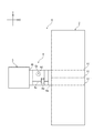
- FIG. 2 is a diagram schematically showing FIG. 1 in a plan view and exemplifying the maximum position of the amplitude of the primary mode of vibration in the direction opposite to the housing for the purification catalyst.
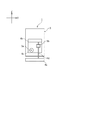
- FIG. 3 is a diagram schematically illustrating FIG. 1 in a cross-sectional view taken along the line AA.
- FIG. 4 is a diagram illustrating a primary mode of vibration in the opposite direction of the engine body corresponding to FIG. 2.
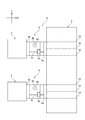
- FIG. 5 is a diagram schematically illustrating FIG. 1 in a plan view and also illustrating the maximum position of the amplitude of the secondary mode of vibration of the engine body in the opposite direction.
- FIG. 1 is a diagram schematically illustrating the configuration of a support system for a purifying catalyst housing of one embodiment in a side view.
- FIG. 2 is a diagram schematically showing FIG. 1 in a plan view and
- FIG. 6 is a diagram illustrating a secondary mode of vibration in the opposite direction of the engine body corresponding to FIG.
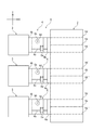
- FIG. 7 is a diagram schematically showing FIG. 1 in a plan view and exemplifying the maximum position of the amplitude of the third-order mode of vibration in the opposite direction of the engine body.
- FIG. 8 is a diagram illustrating a tertiary mode of vibration in the opposite direction of the engine body corresponding to FIG. 7.
- the support system 1 for the purifying catalyst housing according to the embodiment of the present disclosure will be described with reference to the drawings.
- the X direction is the opposite direction (the front-rear direction of the engine body 2) in which the engine body 2 and the purification catalyst housing 3 face each other
- the Y direction is the engine body 2 and the purification catalyst.
- the left-right direction of the housing 3 (the longitudinal direction of the engine body 2 and the direction horizontally orthogonal to the facing direction) and the Z direction are the vertical directions of the engine body 2 and the purification catalyst housing 3.
- the engine body 2 and the purifying catalyst housing 3 are connected by an exhaust pipe, the exhaust pipe is not shown in each drawing of the present embodiment in order to avoid complication.
- the purification catalyst housing support system 1 of the present embodiment includes an engine main body 2, a purification catalyst housing 3, and a support device 4.
- the engine body 2 is a rectangular parallelepiped box-shaped device provided in the vehicle, and generates power for running the vehicle by compressing and mixing fuel and air in each cylinder of the engine body 2 and burning them. Exhaust gas generated by combustion in each cylinder of the engine body 2 flows into the purification catalyst housing 3 through the exhaust pipe.
- the engine body 2 is not limited to a rectangular parallelepiped box shape, and may have another shape such as a cylindrical shape.
- the purification catalyst housing 3 carries various purification catalysts for purifying the purification target components (hydrocarbons, carbon monoxide, particulate matter, NOx, etc.) contained in the exhaust gas generated in the engine body 2 inside. ..
- the purification catalyst housing 3 is a rectangular parallelepiped box-shaped device that is smaller than the engine body 2, and is disposed facing one side surface of the engine body 2 in the left-right direction with a space therebetween.
- the purifying catalyst housing 3 is not limited to a rectangular parallelepiped box shape, and may have another shape such as a cylindrical shape.
- the support device 4 is arranged between the engine body 2 and the purification catalyst housing 3 in the opposite direction in which the engine body 2 and the purification catalyst housing 3 face each other, and is arranged between the engine body 2 and the purification catalyst housing 3. It is connected to both of the housings 3 and supports the purification catalyst housing 3 with respect to the engine body 2.
- the supporting device 4 is composed of L-shaped supporting portions 4a and 4b and linear supporting rods 4c and 4d.
- the supporting portion 4a is connected in a state where the entire L-shaped piece is in contact with the lower portion of the side surface of the engine body 2 on the purification catalyst housing 3 side.
- the supporting portion 4b is connected in such a manner that the entire L-shaped piece is in contact with the side surface of the purification catalyst housing 3 on the engine body 2 side.
- the support rod 4c extends in the opposite direction (horizontal direction) of the engine body 2 and the purification catalyst housing 3, one end thereof is connected to a piece of the support portion 4a, and the other end portion of the support portion 4b. It is connected in one piece.
- the support portion 4d extends in the vertical direction of the engine body 2 and the purification catalyst housing 3, one end thereof is connected to another piece of the support portion 4a, and the other end portion is connected to the other piece of the support portion 4b. It is connected.
- the support portions 4a and 4b and the support rods 4c and 4d are made of a material having sufficient heat resistance to withstand the amount of heat radiated from the engine body 2, and can support the purification catalyst housing 3. It is not limited to the configuration of the present embodiment as long as it is formed in a size and shape that can secure sufficient strength.
- the support portions 4a and 4b and the support rods 4c and 4d are used so as to avoid the heat protector. Be placed.
- the number of support portions 4a and 4b and support rods 4c and 4d installed is not particularly limited.
- the purification catalyst housing 3 and the support device 4 are each provided with n (n ⁇ 1), and each of the support devices 4 is provided with the vibration isolator member 5.
- the anti-vibration member 5 is formed in a cylindrical shape as a whole by sandwiching a damping material (for example, fluororubber or metal fiber) 7 between two opposing fixing disks 6. The anti-vibration member 5 reciprocates in the opposite direction of the fixing disc 6 to damp the vibration in the opposite direction.
- the vibration isolator member 5 has a vibration isolator member 5a for the opposite direction and a vibration isolator member 5b for the vertical direction.
- the anti-vibration member 5a for the opposite direction is arranged so as to be interposed in the middle of the support rod 4c to attenuate the vibration of the engine body 2 in the opposite direction to the purification catalyst housing 3.
- the vertical vibration damping member 5b is disposed in the middle of the support rod 4d to damp vertical vibrations of the engine body 2.
- the vibration isolating members 5a and 5b may have the same shape regardless of their installation positions, or may have different shapes depending on their installation positions.
- the amplitude of the nth-order mode of the vibration in the facing direction of the engine body 2 is among the positions in the left-right direction horizontally orthogonal to the facing direction of the engine body 2.
- the purifying catalyst casing 3 and the supporting device 4 are arranged to face one side surface of the engine body 2 at the maximum n positions. Which mode of the amplitude is attenuated is set according to the number of the purification catalyst housings 3 installed.
- one purification catalyst housing 3 and one support device 4 are arranged at one position Y1 where the amplitude B of the primary mode is maximum (B1).
- the position Y1 is the center position of the engine body 2 in the left-right direction.
- the purification catalyst housing 3 includes an oxidation catalyst, a filter for collecting particulate matter, a selective reduction catalyst, and an ammonia slip catalyst. This is the case when all the particles are stored inside.
- the support device 4 is between Y1'and Y1', which are lines (boundary lines) indicating positions separated by a predetermined distance in the left-right direction of the engine body 2 from a line indicating the position Y1 which is a reference line with respect to the engine body 2. At least one may be arranged at a position facing the region. This region is a region where the maximum amplitude B1 can be sufficiently suppressed if the support device 4 is arranged at a position facing the region.
- a plurality of support devices 4 may be provided in the vertical direction as long as they face the region.
- the support device 4 is preferably arranged within a range from the position where the amplitude becomes zero to the position where the amplitude becomes maximum. In this case, even when the support device 4 cannot be arranged at the position where the amplitude is maximum, the noise generated by the vibration can be effectively reduced.
- the purification catalyst housing 3 and the support device 4 are arranged one by one at the two positions Y2 and Y3 where the amplitude B of the secondary mode is maximum (B2, B3). doing.
- the position Y2 is the central position in the region on the left side of the central position in the left-right direction of the engine body 2.
- the position Y3 is the central position in the region on the right side of the central position in the left-right direction of the engine body 2.
- the number of the purification catalyst housings 3 installed is two, for example, a filter for repairing an oxidation catalyst and a particulate matter is selectively reduced inside the first purification catalyst housing 3. This is a case where the mold catalyst and the ammonia slip catalyst are housed inside the second purification catalyst housing 3.
- the support device 4 is between Y2'and Y2', which are lines (boundary lines) indicating positions separated by a predetermined distance in the left-right direction of the engine body 2 from a line indicating the position Y2 which is a reference line with respect to the engine body 2. At least one may be arranged at a position facing the region. Further, the support device 4 is a line (boundary line) of Y3'and Y3'' which is a line (boundary line) indicating a position separated by a predetermined distance in the left-right direction of the engine body 2 from a line indicating the position Y3 which is a reference line with respect to the engine body 2. At least one may be arranged at a position facing the area between them.
- the purification catalyst housing 3 and the support device 4 are provided at three positions Y4, Y5, and Y6 where the amplitude B of the tertiary mode is maximum (B4, B5, B6). They are arranged one by one.
- the position Y4 is, like the position Y2, a center position in a region on the left side of the center position of the engine body 2 in the left-right direction.
- the position Y5 is the center position in the left-right direction of the engine body 2 as in the position Y1.
- the position Y6 is, like the position Y3, a center position in a region on the right side of the center position of the engine body 2 in the left-right direction.
- the first selective reduction catalyst is placed inside the first purification catalyst housing 3 to provide an oxidation catalyst and a fine particle substance. This is a case where the repair filter is housed inside the second purification catalyst housing 3 and the selective reduction catalyst and the ammonia slip catalyst are housed inside the third purification catalyst housing 3.
- the support device 4 is between Y4'and Y4', which are lines (boundary lines) indicating positions separated by a predetermined distance in the left-right direction of the engine body 2 from a line indicating the position Y4 which is a reference line with respect to the engine body 2. At least one may be arranged at a position facing the region. Further, the support device 4 is a line (boundary line) of Y5'and Y5', which is a line (boundary line) indicating a position separated by a predetermined distance in the left-right direction of the engine body 2 from a line indicating the position Y5 which is a reference line with respect to the engine body 2. At least one may be arranged at a position facing the area between them.
- the support device 4 is a line (boundary line) of Y6'and Y6', which is a line (boundary line) indicating a position separated by a predetermined distance in the left-right direction of the engine body 2 from a line indicating the position Y6 which is a reference line with respect to the engine body 2. It suffices that at least one is arranged at a position facing the region between them.
- One or more anti-vibration members 5a for facing directions are installed in each of the n support devices 4. By doing so, it is possible to attenuate the vibration at each position where the amplitude of the vibration in the opposite direction of the engine body 2 in the nth mode is maximum, and to significantly suppress the vibration in the nth mode.
- the vertical vibration isolator 5b may be installed on at least one of the n support devices 4. By doing so, it is possible to reduce the cost required for installing the vertical vibration-isolating member 5b and save space.
- the purification catalyst housing support system of the present disclosure is useful in that it reduces noise generated by vibrations transmitted from the engine body to the purification catalyst housing.
Landscapes
- Engineering & Computer Science (AREA)
- Chemical & Material Sciences (AREA)
- Combustion & Propulsion (AREA)
- Mechanical Engineering (AREA)
- Chemical Kinetics & Catalysis (AREA)
- General Engineering & Computer Science (AREA)
- Transportation (AREA)
- Health & Medical Sciences (AREA)
- Toxicology (AREA)
- Exhaust Gas After Treatment (AREA)
- Exhaust Silencers (AREA)
- Cooling, Air Intake And Gas Exhaust, And Fuel Tank Arrangements In Propulsion Units (AREA)
Abstract
エンジン本体(2)の一側面にn(n≧1)個の浄化触媒用筐体(3)が対向配置される。エンジン本体(2)とn個の浄化触媒用筐体(3)の間に、防振部材(5)を有する支持装置(4)が配置される。浄化触媒用筐体(3)及び支持装置(4)は、エンジン本体(2)と浄化触媒用筐体(3)とが対向する方向である対向方向に水平に対して水平に直交するエンジン本体(2)の左右方向における位置の内、エンジン本体(2)の対向方向の振動のn次モードの振幅が最大となるn個の位置に各々配置される。
Description
本開示は、浄化触媒用筐体の支持システムに関する。
エンジン(内燃機関)本体に支持フレームを介して排気処理装置を固定するとともに、支持フレームと排気処理装置の接続箇所にダンパを介在させることが提案されている(例えば、特許文献1参照)。
ところで、エンジンの排気処理装置(浄化触媒用筐体)は、エンジン本体に支持される他の装置と比較して大型で、また、エンジン本体や車体への熱害対策として金属製のヒートプロテクタが外側から装着される。このため、エンジン本体からの振動伝達により浄化触媒用筐体から騒音がヒートプロテクタにより増幅されて放射されやすい。浄化触媒用筐体は、高温の排気をその内部に通過させるためにエンジン本体の近くに配置されることもあり、このような場合はより騒音が放射されやすくなる。騒音を低減するためにエンジン本体から浄化触媒用筐体に伝達される振動を低減する必要があるが、上記の特許文献1のようにダンパを介在させるだけでは大きな騒音低減効果は見込めない。
一方、エンジン本体の振動は1次モードや2次モード等複数のモードの振動が重なり合って構成されている。本発明者は、複数のモードの振動の内、いずれかのモードの振動を抑制することでエンジン本体から浄化触媒用筐体に伝達される振動を大幅に低減して、振動により発生する騒音を大幅に低減することができると考えた。
本開示の目的は、エンジン本体から浄化触媒用筐体に伝達される振動により発生する騒音を低減することができる浄化触媒用筐体の支持システムを提供することにある。
本開示の浄化触媒用筐体の支持システムは、
エンジン本体と、
前記エンジン本体の一側面に対向配置されて前記エンジン本体の排気を浄化する浄化触媒を担持した浄化触媒用筐体と、
前記エンジン本体と前記浄化触媒用筐体とが対向する方向である対向方向における前記エンジン本体と前記浄化触媒用筐体の間に配置されるとともに、前記エンジン本体及び前記浄化触媒用筐体の両方に連結されて、前記浄化触媒用筐体を前記エンジン本体に支持する支持装置と、を備え、
前記浄化触媒用筐体及び前記支持装置がそれぞれn(n≧1)個設けられ、
前記支持装置の各々は防振部材を備え、
前記対向方向に対して水平に直交する左右方向における位置の内、前記エンジン本体の前記対向方向の振動のn次モードの振幅が最大となるn個の位置に、前記浄化触媒用筐体及び前記支持装置が前記エンジン本体の一側面に対向配置される。
エンジン本体と、
前記エンジン本体の一側面に対向配置されて前記エンジン本体の排気を浄化する浄化触媒を担持した浄化触媒用筐体と、
前記エンジン本体と前記浄化触媒用筐体とが対向する方向である対向方向における前記エンジン本体と前記浄化触媒用筐体の間に配置されるとともに、前記エンジン本体及び前記浄化触媒用筐体の両方に連結されて、前記浄化触媒用筐体を前記エンジン本体に支持する支持装置と、を備え、
前記浄化触媒用筐体及び前記支持装置がそれぞれn(n≧1)個設けられ、
前記支持装置の各々は防振部材を備え、
前記対向方向に対して水平に直交する左右方向における位置の内、前記エンジン本体の前記対向方向の振動のn次モードの振幅が最大となるn個の位置に、前記浄化触媒用筐体及び前記支持装置が前記エンジン本体の一側面に対向配置される。
本開示によれば、エンジン本体から浄化触媒用筐体に伝達される振動により発生する騒音を低減することができる。
以下、本開示の実施形態の浄化触媒用筐体の支持システム1について、図面を参照しながら説明する。なお、本実施形態の各図面では、X方向をエンジン本体2と浄化触媒用筐体3とが対向する方向である対向方向(エンジン本体2の前後方向)、Y方向をエンジン本体2及び浄化触媒用筐体3の左右方向(エンジン本体2の長手方向であって、対向方向に対して水平に直交する方向)、Z方向をエンジン本体2及び浄化触媒用筐体3の鉛直方向としている。また、エンジン本体2と浄化触媒用筐体3は排気管で接続されているが、本実施形態の各図面では煩雑さを避けるために排気管の図示を省略している。
図1~図3に例示するように、本実施形態の浄化触媒用筐体の支持システム1では、エンジン本体2と浄化触媒用筐体3と支持装置4とを備えている。エンジン本体2は、車両に備わる直方体の箱型形状の装置で、エンジン本体2の各気筒内で燃料と空気を圧縮混合して燃焼させることで車両の走行用の動力を発生させる。エンジン本体2での各気筒内での燃焼により発生した排気は排気管を通じて浄化触媒用筐体3の内部に流れる。なお、エンジン本体2は直方体の箱型形状に限定されず、円筒形状等の他の形状でもよい。
浄化触媒用筐体3は、エンジン本体2で発生した排気に含まれる浄化対象成分(炭化水素、一酸化炭素、微粒子状物質、NOx等)を浄化する各種浄化触媒をその内部に担持している。浄化触媒用筐体3は、エンジン本体2より小さい直方体の箱型形状の装置で、エンジン本体2の左右方向の一側面に離間して対向配置されている。なお、浄化触媒用筐体3は直方体の箱型形状に限定されず、例えば円筒形状等の他の形状でもよい。
支持装置4は、エンジン本体2と浄化触媒用筐体3とが対向する方向である対向方向におけるエンジン本体2と浄化触媒用筐体3の間に配置されるとともに、エンジン本体2及び浄化触媒用筐体3の両方に連結されて、浄化触媒用筐体3をエンジン本体2に対して支持している。
本実施形態では、支持装置4は、L字形状の支持部4a、4bと直線形状の支持棒4c、4dとで構成されている。支持部4aは、そのL字形状の一片全体がエンジン本体2の浄化触媒用筐体3側の側面下部に当接した状態で連結されている。支持部4bは、そのL字形状の一片全体が浄化触媒用筐体3のエンジン本体2側の側面に当接した状態で連結されている。支持棒4cは、エンジン本体2及び浄化触媒用筐体3の対向方向(水平方向)に延在して、その一端部が支持部4aの一片に連結されて、その他端部が支持部4bの一片に連結されている。支持部4dは、エンジン本体2及び浄化触媒用筐体3の鉛直方向に延在して、その一端部が支持部4aの他片に連結されて、その他端部が支持部4bの他片に連結されている。
なお、支持部4a、4b及び支持棒4c、4dは、エンジン本体2から放熱される熱量に耐え得るのに十分な耐熱性を有する材質で形成され、かつ、浄化触媒用筐体3を支持可能な強度を確保できる寸法形状で形成されていればよく、本実施形態の構成には限定されない。エンジン本体2や車体への熱害対策として、浄化触媒用筐体3の表面を外側からヒートプロテクタで覆う場合には、このヒートプロテクタを避けるように支持部4a、4b及び支持棒4c、4dは配置される。支持部4a、4b及び支持棒4c、4dの設置個数は特に限定されない。
本実施形態では、浄化触媒用筐体3及び支持装置4がそれぞれn(n≧1)個設けられ、支持装置4の各々が防振部材5を備える。防振部材5は、2つの対向する固定用の円板6の間に減衰材料(例えばフッ素ゴムや金属繊維)7を挟み込んで全体として円筒に形成されている。防振部材5は、固定用の円板6の対向方向に往復移動してこの対向方向の振動を減衰する。
図1~図3に示す例では、浄化触媒用筐体3及び支持装置4がそれぞれ1(n=1)個設置され、1個の支持装置4に対して2個の防振部材5a、5bが設けられる。すなわち、防振部材5は、対向方向用防振部材5aと鉛直方向用防振部材5bとを有する。対向方向用防振部材5aは、支持棒4cの途中に介在して配置されて、浄化触媒用筐体3に対するエンジン本体2の対向方向の振動を減衰する。鉛直方向用防振部材5bは、支持棒4dの途中に介在して配置されて、エンジン本体2の鉛直方向の振動を減衰する。各防振部材5a、5bは、その設置位置に依らずに同一形状でもよいし、その設置位置に応じて異なる形状としてもよい。
本実施形態の浄化触媒用筐体の支持システム1では、エンジン本体2の対向方向に対して水平に直交する左右方向における位置の内、エンジン本体2の対向方向の振動のn次モードの振幅が最大となるn個の位置に、浄化触媒用筐体3及び支持装置4が1つずつエンジン本体2の一側面に対向配置される。いずれのモードの振幅を減衰させるかは、浄化触媒用筐体3の設置個数に応じて設定される。
例えば、浄化触媒用筐体3の設置個数が1つである場合には、エンジン本体2の対向方向の振動の1(n=1)次モードの振動を減衰させる。図2、図4に例示するように、この1次モードの振幅Bが最大(B1)となる1個の位置Y1に浄化触媒用筐体3及び支持装置4を1つ配置する。位置Y1はエンジン本体2の左右方向の中央位置である。なお、浄化触媒用筐体3の設置個数が1つである場合とは、例えば、酸化触媒、微粒子状物質の捕集用のフィルタ、選択還元型触媒及びアンモニアスリップ触媒を浄化触媒用筐体3の内部に全て収納する場合である。
支持装置4は、エンジン本体2に関して、基準線である位置Y1を示す線からエンジン本体2の左右方向に所定距離離間した位置を示す線(境界線)であるY1’、Y1’’の間の領域に対向する位置に少なくとも1つ配置されていればよい。この領域は、この領域に対向する位置に支持装置4が配置されていれば最大の振幅B1を十分に抑制することができる領域である。支持装置4は、この領域に対向する位置であれば上下方向に複数設けてもよい。なお、支持装置4は振幅がゼロとなる位置から振幅が最大となる位置に向かう範囲内に配置することが好ましい。この場合、振幅が最大となる位置に支持装置4を配置できない場合にも、効果的に振動により発生する騒音を低減することができる。
例えば、浄化触媒用筐体3の設置個数が2つである場合には、エンジン本体2の対向方向の振動の2(n=2)次モードの振動を減衰させる。図5、図6に例示するように、この2次モードの振幅Bが最大(B2、B3)となる2個の位置Y2、Y3に浄化触媒用筐体3及び支持装置4を1つずつ配置している。位置Y2はエンジン本体2の左右方向の中央位置より左側の領域における中央位置である。位置Y3はエンジン本体2の左右方向の中央位置より右側の領域における中央位置である。なお、浄化触媒用筐体3の設置個数が2つである場合とは、例えば、酸化触媒及び微粒子状物質の補修用のフィルタを1つ目の浄化触媒用筐体3の内部に、選択還元型触媒及びアンモニアスリップ触媒を2つ目の浄化触媒用筐体3の内部に収納する場合である。
支持装置4は、エンジン本体2に関して、基準線である位置Y2を示す線からエンジン本体2の左右方向に所定距離離間した位置を示す線(境界線)であるY2’、Y2’’の間の領域に対向する位置に少なくとも1つ配置されていればよい。また、支持装置4は、エンジン本体2に関して、基準線である位置Y3を示す線からエンジン本体2の左右方向に所定距離離間した位置を示す線(境界線)であるY3’、Y3’’の間の領域に対向する位置に少なくとも1つ配置されていればよい。
例えば、浄化触媒用筐体3の設置個数が3つである場合には、エンジン本体2の対向方向の振動の3(n=3)次モードの振動を減衰させる。図7、図8に例示するように、この3次モードの振幅Bが最大(B4、B5、B6)となる3個の位置Y4、Y5、Y6に浄化触媒用筐体3及び支持装置4を1つずつ配置している。位置Y4は、位置Y2と同様に、エンジン本体2の左右方向の中央位置より左側の領域における中央位置である。位置Y5は、位置Y1と同様に、エンジン本体2の左右方向の中央位置である。位置Y6は、位置Y3と同様に、エンジン本体2の左右方向の中央位置より右側の領域における中央位置である。なお、浄化触媒用筐体3の設置個数が3つである場合とは、例えば、第1の選択還元型触媒を1つ目の浄化触媒用筐体3の内部に、酸化触媒及び微粒子状物質の補修用のフィルタを2つ目の浄化触媒用筐体3の内部に、選択還元型触媒及びアンモニアスリップ触媒を3つ目の浄化触媒用筐体3の内部に収納する場合である。
支持装置4は、エンジン本体2に関して、基準線である位置Y4を示す線からエンジン本体2の左右方向に所定距離離間した位置を示す線(境界線)であるY4’、Y4’’の間の領域に対向する位置に少なくとも1つ配置されていればよい。また、支持装置4は、エンジン本体2に関して、基準線である位置Y5を示す線からエンジン本体2の左右方向に所定距離離間した位置を示す線(境界線)であるY5’、Y5’’の間の領域に対向する位置に少なくとも1つ配置されていればよい。また、支持装置4は、エンジン本体2に関して、基準線である位置Y6を示す線からエンジン本体2の左右方向に所定距離離間した位置を示す線(境界線)であるY6’、Y6’’の間の領域に対向する位置に少なくとも1つ配置されていればよい。
対向方向用防振部材5aは、n個の支持装置4の各々に1つ以上設置される。このようにすることで、エンジン本体2の対向方向の振動のn次モードの振幅が最大となる各位置での振動を減衰してn次モードの振動を大幅に抑制することができる。
鉛直方向用防振部材5bは、n個の支持装置4の内の少なくとも1つに設置されればよい。このようにすることで、鉛直方向用防振部材5bの設置に要するコストを低減し、かつ、省スペースとすることができる。
以上より、本実施形態の浄化触媒用筐体の支持システム1によれば、エンジン本体2から浄化触媒用筐体3に伝達される振動により発生する騒音を低減することができる。
本出願は、2019年3月5日付で出願された日本国特許出願(特願2019-039908)に基づくものであり、その内容はここに参照として取り込まれる。
本開示の浄化触媒用筐体の支持システムは、エンジン本体から浄化触媒用筐体に伝達される振動により発生する騒音の低減といった点において有用である。
1 浄化触媒用筐体の支持システム
2 エンジン本体
3 浄化触媒用筐体
4 支持装置
4a、4b 支持部
4c、4d 支持棒
5、5a、5b 防振部材
6 固定用の円板
7 減衰材料
2 エンジン本体
3 浄化触媒用筐体
4 支持装置
4a、4b 支持部
4c、4d 支持棒
5、5a、5b 防振部材
6 固定用の円板
7 減衰材料
Claims (3)
- エンジン本体と、
前記エンジン本体の一側面に対向配置されて前記エンジン本体の排気を浄化する浄化触媒を担持した浄化触媒用筐体と、
前記エンジン本体と前記浄化触媒用筐体とが対向する方向である対向方向における前記エンジン本体と前記浄化触媒用筐体の間に配置されるとともに、前記エンジン本体及び前記浄化触媒用筐体の両方に連結されて、前記浄化触媒用筐体を前記エンジン本体に対して支持する支持装置と、を備え、
前記浄化触媒用筐体及び前記支持装置がそれぞれn(n≧1)個設けられ、
前記支持装置の各々は防振部材を備え、
前記対向方向に対して水平に直交する左右方向における位置の内、前記エンジン本体の前記対向方向の振動のn次モードの振幅が最大となるn個の位置に、前記浄化触媒用筐体及び前記支持装置が前記エンジン本体の一側面に対向配置される浄化触媒用筐体の支持システム。 - 前記防振部材は、前記エンジン本体の前記対向方向の振動を減衰させる対向方向用防振部材を有する、請求項1に記載の浄化触媒用筐体の支持システム。
- n個の前記支持装置の少なくとも1つに備わる前記防振部材は、前記エンジン本体の鉛直方向の振動を減衰させる鉛直方向用防振部材を有する、請求項2に記載の浄化触媒用筐体の支持システム。
Applications Claiming Priority (2)
| Application Number | Priority Date | Filing Date | Title |
|---|---|---|---|
| JP2019039908A JP2020143609A (ja) | 2019-03-05 | 2019-03-05 | 浄化触媒用筐体の支持システム |
| JP2019-039908 | 2019-03-05 |
Publications (1)
| Publication Number | Publication Date |
|---|---|
| WO2020179765A1 true WO2020179765A1 (ja) | 2020-09-10 |
Family
ID=72338343
Family Applications (1)
| Application Number | Title | Priority Date | Filing Date |
|---|---|---|---|
| PCT/JP2020/008829 Ceased WO2020179765A1 (ja) | 2019-03-05 | 2020-03-03 | 浄化触媒用筐体の支持システム |
Country Status (2)
| Country | Link |
|---|---|
| JP (1) | JP2020143609A (ja) |
| WO (1) | WO2020179765A1 (ja) |
Citations (2)
| Publication number | Priority date | Publication date | Assignee | Title |
|---|---|---|---|---|
| JP2002081494A (ja) * | 2000-09-08 | 2002-03-22 | Tokai Rubber Ind Ltd | 車両用制振装置 |
| JP2015105573A (ja) * | 2013-11-28 | 2015-06-08 | 井関農機株式会社 | 作業車の排気処理装置 |
-
2019
- 2019-03-05 JP JP2019039908A patent/JP2020143609A/ja active Pending
-
2020
- 2020-03-03 WO PCT/JP2020/008829 patent/WO2020179765A1/ja not_active Ceased
Patent Citations (2)
| Publication number | Priority date | Publication date | Assignee | Title |
|---|---|---|---|---|
| JP2002081494A (ja) * | 2000-09-08 | 2002-03-22 | Tokai Rubber Ind Ltd | 車両用制振装置 |
| JP2015105573A (ja) * | 2013-11-28 | 2015-06-08 | 井関農機株式会社 | 作業車の排気処理装置 |
Also Published As
| Publication number | Publication date |
|---|---|
| JP2020143609A (ja) | 2020-09-10 |
Similar Documents
| Publication | Publication Date | Title |
|---|---|---|
| JP6832439B2 (ja) | 制振制音装置および船舶ディーゼルエンジン推進動力モジュールシステム | |
| CN205297690U (zh) | 一种发动机ch喷射系统控制单元减震隔热装置 | |
| US20120273648A1 (en) | Exhaust Gas Aftertreatment Support Assembly | |
| JP4941126B2 (ja) | 遮音カバー | |
| EP2818659A1 (en) | Exhaust aftertreatment sensor assembly | |
| CN104895648A (zh) | 排气噪音的有源设计 | |
| JPWO2014174684A1 (ja) | ブルドーザ | |
| KR20110058805A (ko) | 엔진 장치 | |
| KR100754636B1 (ko) | 덕트벽 구조 | |
| JP2020143609A (ja) | 浄化触媒用筐体の支持システム | |
| JP6441450B2 (ja) | 触媒ユニットおよび排気ガス触媒コンバータ | |
| JP2002235800A (ja) | 緩衝装置 | |
| JP4651502B2 (ja) | クリーンルームの防振架構構造 | |
| JP5614233B2 (ja) | 排気部品の遮熱構造 | |
| JP2008277173A (ja) | 燃料電池発電システム用防振装置 | |
| JP4426540B2 (ja) | ディーゼル機関 | |
| KR200490255Y1 (ko) | 매연저감장치 지지 구조체 및 이를 포함하는 지지 시스템 | |
| JP3814111B2 (ja) | 燃焼器構造 | |
| JP2019167934A (ja) | 後処理装置 | |
| JP6515967B2 (ja) | 車両用パワートレインユニット | |
| KR102206746B1 (ko) | 농기계의 배기가스 후처리 장치의 장착구조 | |
| KR102807895B1 (ko) | 디젤 발전기 | |
| CN220929520U (zh) | 一种车辆排气系统及车辆 | |
| JP4531772B2 (ja) | エアフィルタシステム | |
| WO2017155422A1 (en) | Exhaust-gas discharging device |
Legal Events
| Date | Code | Title | Description |
|---|---|---|---|
| 121 | Ep: the epo has been informed by wipo that ep was designated in this application |
Ref document number: 20767370 Country of ref document: EP Kind code of ref document: A1 |
|
| NENP | Non-entry into the national phase |
Ref country code: DE |
|
| 122 | Ep: pct application non-entry in european phase |
Ref document number: 20767370 Country of ref document: EP Kind code of ref document: A1 |