WO2020179694A1 - 内燃機関の吸気構造 - Google Patents
内燃機関の吸気構造 Download PDFInfo
- Publication number
- WO2020179694A1 WO2020179694A1 PCT/JP2020/008416 JP2020008416W WO2020179694A1 WO 2020179694 A1 WO2020179694 A1 WO 2020179694A1 JP 2020008416 W JP2020008416 W JP 2020008416W WO 2020179694 A1 WO2020179694 A1 WO 2020179694A1
- Authority
- WO
- WIPO (PCT)
- Prior art keywords
- passage
- intake
- internal combustion
- combustion engine
- cylinder head
- Prior art date
Links
Images


Classifications
-
- F—MECHANICAL ENGINEERING; LIGHTING; HEATING; WEAPONS; BLASTING
- F02—COMBUSTION ENGINES; HOT-GAS OR COMBUSTION-PRODUCT ENGINE PLANTS
- F02B—INTERNAL-COMBUSTION PISTON ENGINES; COMBUSTION ENGINES IN GENERAL
- F02B31/00—Modifying induction systems for imparting a rotation to the charge in the cylinder
- F02B31/04—Modifying induction systems for imparting a rotation to the charge in the cylinder by means within the induction channel, e.g. deflectors
-
- F—MECHANICAL ENGINEERING; LIGHTING; HEATING; WEAPONS; BLASTING
- F02—COMBUSTION ENGINES; HOT-GAS OR COMBUSTION-PRODUCT ENGINE PLANTS
- F02D—CONTROLLING COMBUSTION ENGINES
- F02D9/00—Controlling engines by throttling air or fuel-and-air induction conduits or exhaust conduits
- F02D9/08—Throttle valves specially adapted therefor; Arrangements of such valves in conduits
- F02D9/10—Throttle valves specially adapted therefor; Arrangements of such valves in conduits having pivotally-mounted flaps
-
- F—MECHANICAL ENGINEERING; LIGHTING; HEATING; WEAPONS; BLASTING
- F02—COMBUSTION ENGINES; HOT-GAS OR COMBUSTION-PRODUCT ENGINE PLANTS
- F02F—CYLINDERS, PISTONS OR CASINGS, FOR COMBUSTION ENGINES; ARRANGEMENTS OF SEALINGS IN COMBUSTION ENGINES
- F02F1/00—Cylinders; Cylinder heads
- F02F1/24—Cylinder heads
- F02F1/42—Shape or arrangement of intake or exhaust channels in cylinder heads
-
- F—MECHANICAL ENGINEERING; LIGHTING; HEATING; WEAPONS; BLASTING
- F02—COMBUSTION ENGINES; HOT-GAS OR COMBUSTION-PRODUCT ENGINE PLANTS
- F02M—SUPPLYING COMBUSTION ENGINES IN GENERAL WITH COMBUSTIBLE MIXTURES OR CONSTITUENTS THEREOF
- F02M35/00—Combustion-air cleaners, air intakes, intake silencers, or induction systems specially adapted for, or arranged on, internal-combustion engines
- F02M35/10—Air intakes; Induction systems
- F02M35/104—Intake manifolds
-
- F—MECHANICAL ENGINEERING; LIGHTING; HEATING; WEAPONS; BLASTING
- F02—COMBUSTION ENGINES; HOT-GAS OR COMBUSTION-PRODUCT ENGINE PLANTS
- F02M—SUPPLYING COMBUSTION ENGINES IN GENERAL WITH COMBUSTIBLE MIXTURES OR CONSTITUENTS THEREOF
- F02M35/00—Combustion-air cleaners, air intakes, intake silencers, or induction systems specially adapted for, or arranged on, internal-combustion engines
- F02M35/16—Combustion-air cleaners, air intakes, intake silencers, or induction systems specially adapted for, or arranged on, internal-combustion engines characterised by use in vehicles
-
- F—MECHANICAL ENGINEERING; LIGHTING; HEATING; WEAPONS; BLASTING
- F02—COMBUSTION ENGINES; HOT-GAS OR COMBUSTION-PRODUCT ENGINE PLANTS
- F02M—SUPPLYING COMBUSTION ENGINES IN GENERAL WITH COMBUSTIBLE MIXTURES OR CONSTITUENTS THEREOF
- F02M69/00—Low-pressure fuel-injection apparatus ; Apparatus with both continuous and intermittent injection; Apparatus injecting different types of fuel
- F02M69/04—Injectors peculiar thereto
-
- Y—GENERAL TAGGING OF NEW TECHNOLOGICAL DEVELOPMENTS; GENERAL TAGGING OF CROSS-SECTIONAL TECHNOLOGIES SPANNING OVER SEVERAL SECTIONS OF THE IPC; TECHNICAL SUBJECTS COVERED BY FORMER USPC CROSS-REFERENCE ART COLLECTIONS [XRACs] AND DIGESTS
- Y02—TECHNOLOGIES OR APPLICATIONS FOR MITIGATION OR ADAPTATION AGAINST CLIMATE CHANGE
- Y02T—CLIMATE CHANGE MITIGATION TECHNOLOGIES RELATED TO TRANSPORTATION
- Y02T10/00—Road transport of goods or passengers
- Y02T10/10—Internal combustion engine [ICE] based vehicles
- Y02T10/12—Improving ICE efficiencies
Definitions
- the present invention relates to an intake structure for an internal combustion engine.
- Patent Document 1 discloses a structure in which a portion that promotes diffusion and vaporization of fuel is formed in an intake port.
- An object of the present invention is to provide a structure in which an injector can be arranged closer to a combustion chamber.
- the mounting boss (113) is In the inward and outward directions (BD) of the bend of the bent portion (110a), the position is biased to the outer side (OUT) rather than the inner side (IN), and,
- the passage member (11) is viewed from the side of the connection surface (111a), it projects in a direction (L2) intersecting the cylinder axis direction (L1′).
- An intake structure of an internal combustion engine is provided.
- the mounting boss (113) has a hole (113a) into which the injector (16) is inserted and which defines a fuel injection direction (L2) of the injector,
- the axial direction (L2) of the hole (113a) is offset from the center line (CT) of the intake passage (11a).
- a throttle (12) attached to the upstream end (112) of the passage member (11).
- the drum portion (121) of the throttle (12) is located inside (IN) in the inward/outward direction (BD) of the bend of the bend portion (110a).
- the passage member (11), The first intake passage (11a), which is the intake passage, and A second intake passage (11b) different from the first intake passage is formed,
- the intake port (321) of the cylinder head (32) is A first passage (321a) communicating with the first intake passage (11a), A second passage (321b) communicating with the second intake passage (11b), The first passage (321a) and the second passage (321b) and a merging passage merged on the downstream side (321c),
- the axial direction (L2) of the hole (113a) passes through the confluence passage (321c).
- a head cover (31) is provided on the cylinder head (32).
- the cylinder head (32) has a connection surface (32a) to which the connection surface (111a) of the passage member (11) is connected,
- the head cover (31) is a first avoiding portion that avoids the injector (16) at a portion adjacent to the connecting surface (32a) of the cylinder head (32) and overlapping with the cylinder head (32). 31a) is included.
- the cylinder head (32) is The connecting surface (32a) to which the connecting surface (111a) of the passage member (11) is connected, A second avoiding portion (32b) which is formed at a portion adjacent to the connecting surface (32a) and avoids the injector (16).
- the protrusion amount of the mounting boss can be suppressed, and the injector can be arranged at a position closer to the cylinder head, that is, the combustion chamber. Moreover, it is possible to reduce restrictions on the arrangement of other components around the mounting boss. Moreover, the injector can be easily attached.
- the fuel injection direction of the injector can be directed in a direction closer to the combustion chamber.
- the space inside the bent portion can be utilized as the arrangement space for the throttle drum.
- the injector can be arranged at a position closer to the combustion chamber while avoiding interference with the head cover.
- the injector can be arranged at a position closer to the combustion chamber while avoiding interference with the cylinder head.
- FIG. 2 is a sectional view taken along the line AA of FIG.
- FIG. 3 is a sectional view taken along line BB of FIG. 2.
- FIG. 3 is a sectional view taken along line CC of FIG.
- FIG. 5 is a view of the passage member of FIG. 5 as viewed from the side of one connecting surface.
- FIG. 5 is a view of the passage member of FIG. 5 as viewed from the side of the other connecting surface.
- FIG. 7 is a sectional view taken along line DD of FIG.
- FIG. 6 is a sectional view taken along line EE of FIG. 4.
- FIG. 6 is a sectional view taken along line FF of FIG. 4.
- FIG. 1 is a side view of a saddle riding type vehicle 1 to which the present invention is applied.
- the present invention is also applicable to other types of vehicles such as four-wheel vehicles.
- the saddle type vehicle 1 is a naked type motorcycle.
- the saddle-mounted vehicle 1 may be referred to as a vehicle 1.
- Fr, Rr, U, D, L, and R indicate the front side, the rear side, the upper side, the lower side, the left side, and the right side with respect to the forward direction of the vehicle 1, respectively.
- upstream side and downstream side mean the upstream side and the downstream side in the airflow direction of the intake air unless otherwise specified.
- the vehicle 1 includes an internal combustion engine 3 supported by a vehicle body frame 2 between the front wheel FW and the rear wheel RW.
- the front wheel FW is a steering wheel
- the rear wheel RW is a drive wheel rotated by the driving force of the engine 3.
- the front wheel FW is rotatably supported by the front fork 4.
- the body frame 2 includes a head pipe 20 that operably supports the front fork 4 and the handlebar 5 connected to the front fork 4, a main frame 21 extending rearward from the head pipe 20, and left and right extending downward from the rear portion of the main frame 21.
- the swing arm 6 is swingably supported on the main frame 21 via a pivot frame 26.
- the swing arm 6 rotatably supports the rear wheel RW.
- the driving force of the internal combustion engine 3 is transmitted to the rear wheels RW via a chain (not shown).
- a rear cushion 7 is provided between the swing arm 6 and the seat rail 24.
- the fuel tank 8 is supported on the main frame 21, and a seat 9 on which the rider is seated is arranged behind the fuel tank 8.
- the seat 9 is supported by the seat rail 24.
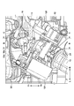
- FIG. 2 is a cross-sectional view taken along the line AA of FIG. 1, which is a top view of the vicinity of the passage member 11.
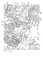
- FIG. 3 is a sectional view taken along line BB of FIG. 2
- FIG. 4 is a sectional view taken along line CC of FIG.
- the internal combustion engine 3 is a SOHC type two-valve single-cylinder four-stroke internal combustion engine, and includes a head cover 31, a cylinder head 32, a cylinder block 33, and a crankcase 34 in order from the top.
- the internal combustion engine 3 is tilted forward and supported by the vehicle body frame 2, and the cylinder axis L1 is tilted forward with respect to the vertical direction.
- the line L1 indicates the cylinder axis, and indicates the direction of the central axis of the cylinder bore 33a of the cylinder block 33.
- the piston 33b in the cylinder bore 33a reciprocates in the cylinder axis L1 direction to rotate the crankshaft 34a.
- the crankshaft 34a is oriented in the left-right direction (vehicle width direction).
- the cylinder head 32 includes a combustion chamber 320, an intake port 321 and an exhaust port 322 that communicate with the combustion chamber 320.
- the intake port 321 opens to the rear side of the cylinder head 32, and the exhaust port 322 opens to the front side of the cylinder head 32.
- the intake port 321 and the exhaust port 322 are opened and closed by an intake valve and an exhaust valve (both not shown) driven by the valve operating mechanism 333.
- the exhaust structure 15 of the internal combustion engine 3 includes an exhaust pipe 15 a connected to the cylinder head 32.
- the exhaust pipe 15a forms an exhaust passage communicating with the exhaust port 322 of the cylinder head 32, and the exhaust gas is discharged through the exhaust pipe 15a.
- the intake structure 10 of the internal combustion engine 3 includes a passage member 11 connected to the cylinder head 32, a throttle 12 connected to the passage member 11, and a connecting pipe 13 connecting the throttle 12 and the air cleaner box 14.
- An air cleaner is arranged in the air cleaner box 14.
- the connecting pipe 13 extends from the air cleaner box 14 to the front side of the vehicle 1 through the side of the main frame 21, and is bent to the right side of the vehicle 1 (see FIG. 2).
- the air purified by the air cleaner is introduced into the intake port 321 of the cylinder head 32 through the intake passages of the connecting pipe 13, the throttle 12, and the passage member 11.
- the cylinder head 32 has a connecting surface 32a to which the passage member 11 is connected via a gasket, and the intake port 113a is open to the connecting surface 32a.
- a mounting boss 113 is provided on the passage member 11, and an injector 16 is mounted on the mounting boss 113.
- the injector 16 injects the fuel contained in the fuel tank 8 into the intake port 321.
- the mounting boss 113 has a hole 113a into which the tip side of the injector 16 is inserted.
- the line L2 in FIG. 3 indicates the axial direction of the hole 113a, and indicates the fuel injection direction of the injector 16.
- the intake port 321 includes an upper passage 321a and a lower passage 321b which are vertically divided, and a confluence passage 321c thereof.
- the upper passage 321a and the lower passage 321b open on the connection surface 32a on the upstream side thereof, and merge on the downstream side to form a merged passage 321c.
- the merging passage 321c communicates with the combustion chamber 320. By partitioning the passage of the intake port 321 at the top and bottom, tumble can be generated in the combustion chamber 320.
- the fuel injection port of the injector 16 faces the upper passage 321a, and the line L2 passes through the merging passage 321c.
- the fuel injected from the injector 16 can easily go toward the merging passage 321c, and the mixing of air and fuel through the upper passages 321a and the lower passages 321b can be promoted.
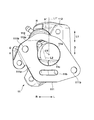
- FIG. 5 is a plan view of the passage member 11, more precisely, a view seen from the head cover 31 side in the direction of the line L1.
- FIG. 6 is a view of the passage member 11 as seen from the side of the connection surface 111a connected to the cylinder head 32 via the gasket.
- FIG. 7 is a view of the passage member 11 viewed from the side of the connection surface 112a connected to the throttle 12.
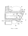
- FIG. 8 is a cross-sectional view taken along the line DD of FIG.
- the passage member 11 integrally includes a tubular pipe portion 110, a flange portion 111 at one end of the pipe portion 110, and a flange portion 112 at the other end of the pipe portion 110.
- the end surface of the flange portion 111 is a connection surface 111a connected to the connection surface 32a of the cylinder head 32 via a gasket.
- the end surface of the flange portion 112 is a connection surface 112a connected to the throttle 12.
- the passage member 11 includes an upper intake passage 11a formed from the connection surface 112a to the connection surface 111a and a lower intake passage 11b.
- the upper intake passage 11a and the lower intake passage 11b are partitioned by a wall portion 11c.
- the upper intake passage 11a and the lower intake passage 11b are partitioned and opened from each other on the connecting surface 111a, the upper intake passage 11a communicates with the upper passage 321a of the intake port 321 and the lower intake passage 11b is the intake port 321. It communicates with the lower passage 321b.
- the upper intake passage 11a and the lower intake passage 11b merge on the upstream side, and one opening is formed on the connecting surface 112a to communicate with the throttle 12.
- the intake structure having a plurality of passages (passages 11a and 321a and passages 11b and 321b) of the present embodiment does not have individual control valves and controls intake with a common throttle 12. ..
- the pipe portion 110 extends linearly on the side of the flange portion 111 in a direction orthogonal to the line L1, and on the side of the flange portion 112, the passage direction is bent to the left side in a plan view at the bent portion 110a.
- the length of the vehicle 1 in the front-rear direction can be shortened, and the passage lengths of the upper intake passage 11a and the lower intake passage 11b can be secured longer, or the layout of peripheral parts can be improved. improves.
- the arrow BD indicates the bending inside / outside direction of the bending portion 110a, and the outside is indicated by OUT and the inside is indicated by IN.
- the inner portion 110b and the outer portion 110c correspond to the inner portion and the outer portion in the inner / outer direction BD.
- the inner 110b of the bent portion 110a is located on the left side and the outer 110c is located on the right side in the vehicle width direction of the vehicle 1.
- the mounting boss 113 is integrally formed with the flange portion 111, and a part of the mounting boss 113 extends to the pipe portion 110 and protrudes outward (in the line L2 direction) from the flange portion 111 and the pipe portion 110.
- the mounting boss 113 is a tubular portion forming the hole 113a, and the hole 113a communicates with the upper intake passage 11a.
- the tubular mounting boss 113 is arranged so close to the connecting surface 111a that the outer peripheral edge thereof comes into contact with the connecting surface 111a.
- the injector 16 can be arranged at a position closer to the combustion chamber 320, and fuel can be injected at a position closer to the combustion chamber 320.
- the line L2 which is the axial direction of the hole 113a, passes through a position offset from the center line CT of the upper intake passage 11a so that the line L2 points to a deeper position of the intake port 321 (that is, the merging portion 321c). , Holes 113a are formed. This also contributes to injecting fuel from the injector 16 closer to the combustion chamber 320.
- the flange portion 111 is formed with fastening portions 111b (holes for bolts in the case of this embodiment) on opposite sides of the upper intake passage 11a, and is fixed to the cylinder head 32 by the fastening portion 111b.
- the mounting boss 113 is arranged at a position offset in the radial direction with respect to the centerline CT.
- the protruding direction (direction of line L2) is a direction intersecting with the line L1'.
- the line L1' is a line that passes through the center line CT and is parallel to the line L1 and indicates the cylinder axis direction.
- the mounting boss of the injector is arranged on the line L1' of FIG. 5 when viewed from the connection surface 111a side, and the protruding direction is also the cylinder axis direction.
- the mounting boss 113 is offset in the radial direction with respect to the center line CT, and the protruding direction intersects the cylinder axis direction, whereby the protruding height H in the upward direction (direction of the line L1) is increased. Can be lowered.
- FIG. 6 shows an expected protrusion height H'when a similar mounting boss is formed on the line CL.
- the protrusion height H' has a larger protrusion amount than the protrusion height H.
- the mounting boss 113 can be arranged at a position close to the cylinder head 32 while avoiding interference with the head cover 31 and the cylinder head 32. That is, the injector 16 can be arranged at a position closer to the combustion chamber 320 of the cylinder head 32, and fuel can be injected closer to the combustion chamber 320.
- the passage member 11 is bent at the bent portion 110a.
- the space S2 in which the inner side 110b of the bent portion 110a is adjacent to the left side is narrower than the space S1 adjacent to the outer side 110c. Therefore, in the present embodiment, the mounting boss 113 is arranged at a position biased to the outside (OUT) rather than the inside (IN) in the inward and outward directions of bending of the bent portion 110a. As a result, the injector 16 attached to the mounting boss 113 is located on the side of the wider space S1, and restrictions on the arrangement of other parts around the mounting boss 113 can be reduced.
- FIGS. 2 to 4, 9 and 10 are sectional views taken along line EE of FIG. 4 and FIG. 10 is a sectional view taken along line FF of FIG.
- the throttle 12 of this embodiment is arranged near the center in the vehicle width direction of the vehicle 1. As a result, the protrusion of the throttle 12 in the vehicle width direction can be suppressed.
- the throttle 12 of this embodiment includes a valve body portion 120 and a drum portion 121. 9 and 10 show the drum portion 121 in a transparent view of the case portion thereof.
- the drum 121 portion includes a drum 121a which is connected to the throttle grip 5a via a wire (not shown) and rotates by operating the throttle grip 5a.
- the valve body 120 is provided coaxially with the drum 121a, and is provided with a butterfly throttle valve 120a that controls the intake air amount by rotating the drum 121a.
- the drum portion 121 is arranged laterally of the passage member 11, and particularly, it is arranged adjacent to the inner side 110b of the bent portion 110a instead of the outer side 110c. That is, the drum portion 121 is arranged inside (IN) in the bending inside / outside direction of the bending portion 110a with respect to the passage member 11, and is arranged in the region S2 of FIGS. 5 and 8. A region S2 that is relatively narrower than the region S1 can be used as a space for disposing the drum portion 121.
- the injector 16 is provided with a connection portion 16a (see FIG. 2) to which a fuel pipe (not shown) is connected.
- the injector 16 as a whole is arranged on the right side of the center of the vehicle 1 in the vehicle width direction, while the connecting portion 16a faces the center of the vehicle 1 in the vehicle width direction. The protrusion of the fuel pipe in the vehicle width direction can be suppressed.
- the head cover 31 has an avoidance portion 31a
- the cylinder head 32 has an avoidance portion 32b.
- Both the avoiding portion 31a and the avoiding portion 32b are concave portions that are recessed on the side opposite to the passage member 11 (that is, the front side of the vehicle 1) in the direction parallel to the center line CT.
- the avoiding portion 31a is formed in a portion of the lower portion of the head cover 31 that is adjacent to the connection surface 32a and overlaps with the cylinder head 32, and in particular, a peripheral portion of the head cover 31 that abuts on the deck surface of the cylinder head 32. It is formed in a certain range including the lower surface.
- the avoiding portion 32b is formed around the deck surface of the cylinder head 32 so as to vertically overlap the same portion as the avoiding portion 31a, and is formed on the upper portion of the connecting surface 32a.
- the injector 16 can be arranged at a position closer to the combustion chamber 320.
- the intake port 320 has the two intake passages 321a and 321b
- the passage member 11 has the two intake passages 11a and 11b corresponding to the intake passages 321a and 321b. May be included.
Landscapes
- Engineering & Computer Science (AREA)
- Chemical & Material Sciences (AREA)
- Combustion & Propulsion (AREA)
- Mechanical Engineering (AREA)
- General Engineering & Computer Science (AREA)
- Fuel-Injection Apparatus (AREA)
- Cylinder Crankcases Of Internal Combustion Engines (AREA)
Abstract
内燃機関の吸気構造は、シリンダヘッドに接続され、吸気通路を形成する通路部材と、前記通路部材に設けられ、燃料を噴射するインジェクタが取り付けられる取付ボスと、を備える。前記通路部材は、前記吸気通路の通路方向を屈曲させる屈曲部と、前記シリンダヘッドに接続される接続面と、を含む。前記取付ボスは、前記屈曲部の屈曲の内外方向で、内側よりも外側に偏った位置にあり、かつ、前記通路部材を前記接続面の側から見た場合、シリンダ軸線方向に対して交差する方向に突出している。
Description
本発明は内燃機関の吸気構造に関する。
インジェクタ(燃料噴射弁)により吸気ポートへ燃料を噴射する内燃機関においては、吸気ポートの周壁に燃料が付着する場合があり、これにより内燃機関の燃焼効率が低下する場合がある。特許文献1にはその対策として、吸気ポートに燃料の拡散・気化を促進する部位を形成した構造が開示されている。
インジェクタから噴射された燃料を効率的に燃焼室に供給するために、インジェクタをできるだけ燃焼室に近い位置に配置することが有効である。しかし、インジェクタを燃焼室により近い位置に配置するためには、シリンダヘッドやヘッドカバーとの干渉に関する構造的な課題がある。
本発明の目的は、インジェクタを燃焼室により近い位置に配置可能な構造を提供することにある。
請求項1の本発明によれば、
シリンダヘッド(32)に接続され、吸気通路(11a)を形成する通路部材(11)と、
前記通路部材(11)に設けられ、燃料を噴射するインジェクタ(16)が取り付けられる取付ボス(113)と、
を備えた内燃機関(3)の吸気構造(10)であって、
前記通路部材(11)は、
前記吸気通路(11a)の通路方向を屈曲させる屈曲部(110a)と、
前記シリンダヘッド(32)に接続される接続面(111a)と、を含み、
前記取付ボス(113)は、
前記屈曲部(110a)の屈曲の内外方向(BD)で、内側(IN)よりも外側(OUT)に偏った位置にあり、かつ、
前記通路部材(11)を前記接続面(111a)の側から見た場合、シリンダ軸線方向(L1')に対して交差する方向(L2)に突出している、
ことを特徴とする内燃機関の吸気構造が提供される。
請求項2の本発明によれば、
前記取付ボス(113)は、前記インジェクタ(16)が挿入され、該インジェクタの燃料噴射方向(L2)を規定する穴(113a)を有し、
前記穴(113a)の軸線方向(L2)は、前記吸気通路(11a)の中心線(CT)からオフセットしている。
前記取付ボス(113)は、前記インジェクタ(16)が挿入され、該インジェクタの燃料噴射方向(L2)を規定する穴(113a)を有し、
前記穴(113a)の軸線方向(L2)は、前記吸気通路(11a)の中心線(CT)からオフセットしている。
請求項3の本発明によれば、
前記通路部材(11)の上流側の端部(112)に取り付けられるスロットル(12)を更に備え、
前記スロットル(12)のドラム部(121)は、前記屈曲部(110a)の屈曲の内外方向(BD)で、内側(IN)に位置している。
前記通路部材(11)の上流側の端部(112)に取り付けられるスロットル(12)を更に備え、
前記スロットル(12)のドラム部(121)は、前記屈曲部(110a)の屈曲の内外方向(BD)で、内側(IN)に位置している。
請求項4の本発明によれば、
前記通路部材(11)は、
前記吸気通路である第一吸気通路(11a)と、
前記第一吸気通路とは別の第二吸気通路(11b)と、を形成し、
前記シリンダヘッド(32)の吸気ポート(321)は、
前記第一吸気通路(11a)と連通した第一通路(321a)と、
前記第二吸気通路(11b)と連通した第二通路(321b)と、
前記第一通路(321a)と前記第二通路(321b)とが下流側で合流した合流通路(321c)と、を含み、
前記穴(113a)の軸線方向(L2)は、前記合流通路(321c)を通過している。
前記通路部材(11)は、
前記吸気通路である第一吸気通路(11a)と、
前記第一吸気通路とは別の第二吸気通路(11b)と、を形成し、
前記シリンダヘッド(32)の吸気ポート(321)は、
前記第一吸気通路(11a)と連通した第一通路(321a)と、
前記第二吸気通路(11b)と連通した第二通路(321b)と、
前記第一通路(321a)と前記第二通路(321b)とが下流側で合流した合流通路(321c)と、を含み、
前記穴(113a)の軸線方向(L2)は、前記合流通路(321c)を通過している。
請求項5の本発明によれば、
前記シリンダヘッド(32)には、ヘッドカバー(31)が設けられ、
前記シリンダヘッド(32)は、前記通路部材(11)の前記接続面(111a)が接続される接続面(32a)を有し、
前記ヘッドカバー(31)は、前記シリンダヘッド(32)の前記接続面(32a)に隣接し、かつ、前記シリンダヘッド(32)と重なる部分において、前記インジェクタ(16)を避ける第一の避け部(31a)を含む。
前記シリンダヘッド(32)には、ヘッドカバー(31)が設けられ、
前記シリンダヘッド(32)は、前記通路部材(11)の前記接続面(111a)が接続される接続面(32a)を有し、
前記ヘッドカバー(31)は、前記シリンダヘッド(32)の前記接続面(32a)に隣接し、かつ、前記シリンダヘッド(32)と重なる部分において、前記インジェクタ(16)を避ける第一の避け部(31a)を含む。
請求項6の本発明によれば、
前記シリンダヘッド(32)は、
前記通路部材(11)の前記接続面(111a)が接続される接続面(32a)と、
前記接続面(32a)に隣接した部位に形成され、前記インジェクタ(16)を避ける第二の避け部(32b)と、を含む。
前記シリンダヘッド(32)は、
前記通路部材(11)の前記接続面(111a)が接続される接続面(32a)と、
前記接続面(32a)に隣接した部位に形成され、前記インジェクタ(16)を避ける第二の避け部(32b)と、を含む。
請求項1の本発明によれば、前記取付ボスの突出量を抑えることができ、前記シリンダヘッド、つまり、燃焼室により近い位置に前記インジェクタを配置できる。しかも、前記取付ボスの周辺における他部品の配置の制約を少なくすることができる。また、前記インジェクタの取り付けをしやすい。
請求項2の本発明によれば、前記インジェクタの燃料噴射方向を、燃焼室により近い方向に指向させることができる。
請求項3の本発明によれば、前記屈曲部の内側のスペースを前記スロットルドラムの配置スペースとして活用できる。
請求項4の本発明によれば、燃焼室内にタンブルを発生させる吸気構造を採用した場合において、合流後の吸気と燃料との混合を促進することができる。
請求項5の本発明によれば、前記ヘッドカバーとの干渉を回避しつつ、燃焼室により近い位置に前記インジェクタを配置できる。
請求項6の本発明によれば、前記シリンダヘッドとの干渉を回避しつつ、燃焼室により近い位置に前記インジェクタを配置できる。
以下、添付図面を参照して実施形態を詳しく説明する。尚、以下の実施形態は特許請求の範囲に係る発明を限定するものではなく、また実施形態で説明されている特徴の組み合わせの全てが発明に必須のものとは限らない。実施形態で説明されている複数の特徴のうち二つ以上の特徴が任意に組み合わされてもよい。また、同一若しくは同様の構成には同一の参照番号を付し、重複した説明は省略する。
<鞍乗型車両>
図1は本発明の適用例である鞍乗型車両1の側面図である。本実施形態では、鞍乗型車両1に本発明を適用した例を説明するが、本発明は四輪車等、他の種類の車両にも適用可能である。
図1は本発明の適用例である鞍乗型車両1の側面図である。本実施形態では、鞍乗型車両1に本発明を適用した例を説明するが、本発明は四輪車等、他の種類の車両にも適用可能である。
鞍乗型車両1は、ネイキッドタイプの自動二輪車である。以下、鞍乗型車両1のことを車両1と呼ぶ場合がある。また、各図において、Fr、Rr、U、D、L、Rは、それぞれ車両1の前進方向を基準として、前側、後側、上側、下側、左側、右側を示す。また、上流側、下流側という時は、特に断わらない限り吸気の気流方向で上流側、下流側を意味する。
車両1は、前輪FWと後輪RWとの間に、車体フレーム2に支持された内燃機関3を備える。前輪FWは操舵輪であり、後輪RWはエンジン3の駆動力で回転される駆動輪である。前輪FWはフロントフォーク4により回転自在に支持される。
車体フレーム2は、フロントフォーク4及びフロントフォーク4に連結されるハンドル5を操向可能に支持するヘッドパイプ20、ヘッドパイプ20から後方に延びるメインフレーム21、メインフレーム21の後部から下方へ延びる左右一対の下部フレーム22、メインフレーム21の前部から下方へ延びるダウンフレーム23、メインフレーム21の後部から後方へ延びる左右一対のシートレール24、シートレール24と下部フレーム22とを連結するステー25を含む。
メインフレーム21にはピボットフレーム26を介してスイングアーム6が揺動自在に支持されている。スイングアーム6は後輪RWを回転自在に支持する。内燃機関3の駆動力は不図示のチェーンを介して後輪RWに伝達される。スイングアーム6とシートレール24との間にはリアクッション7が設けられている。燃料タンク8は、メインフレーム21上に支持され、燃料タンク8の後方にライダが着座するシート9が配置されている。シート9はシートレール24に支持されている。
<内燃機関及び周辺構造>
図1~図4を参照して内燃機関3及びその周辺構造について説明する。図2は図1のA-A線断面図であり、通路部材11の付近を上から見た図である。図3は図2のB-B線断面図、図4は図2のC-C線断面図である。
図1~図4を参照して内燃機関3及びその周辺構造について説明する。図2は図1のA-A線断面図であり、通路部材11の付近を上から見た図である。図3は図2のB-B線断面図、図4は図2のC-C線断面図である。
内燃機関3は、SOHC型2バルブの単気筒4ストローク内燃機関であり、上から順に、ヘッドカバー31、シリンダヘッド32、シリンダブロック33及びクランクケース34を備える。内燃機関3は前傾されて車体フレーム2に支持されており、シリンダ軸線L1は上下方向に対して前側に傾斜している。線L1はシリンダ軸線を示し、シリンダブロック33のシリンダボア33aの中心軸線方向を示す。シリンダボア33a内のピストン33bがシリンダ軸線L1方向に往復運動し、クランク軸34aを回転させる。クランク軸34aは左右方向(車幅方向)を指向している。
シリンダヘッド32は、燃焼室320と、燃焼室320に連通した吸気ポート321及び排気ポート322を含む。吸気ポート321はシリンダヘッド32の後側に開口し、排気ポート322はシリンダヘッド32の前側に開口している。吸気ポート321、排気ポート322は、動弁機構333で駆動される吸気バルブ及び排気バルブ(いずれも図示省略)によって開閉される。
内燃機関3の排気構造15は、シリンダヘッド32に接続された排気管15aを含む。排気管15aはシリンダヘッド32の排気ポート322と連通する排気通路を形成し、燃焼ガスが排気管15aを介して排出される。
内燃機関3の吸気構造10は、シリンダヘッド32に接続された通路部材11、通路部材11に接続されたスロットル12、スロットル12とエアクリーナボックス14とを接続する接続管13とを含む。エアクリーナボックス14にはエアクリーナが配置されている。接続管13は、エアクリーナボックス14からメインフレーム21の側方を通って車両1の前側へ延設されており、かつ、車両1の右側に屈曲している(図2参照)。エアクリーナで浄化された空気は、接続管13、スロットル12及び通路部材11の各吸気通路を通ってシリンダヘッド32の吸気ポート321に導入される。シリンダヘッド32は通路部材11がガスケットを介して接続される接続面32aを有し、吸気ポート113aは接続面32aに開口している。
通路部材11には取付ボス113が設けられ、取付ボス113にはインジェクタ16が取り付けられている。インジェクタ16は燃料タンク8に収容された燃料を吸気ポート321内に噴射する。取付ボス113は、インジェクタ16の先端側が挿入される穴113aを有する。図3における線L2は、穴113aの軸線方向を示しており、インジェクタ16の燃料噴射方向を示している。
本実施形態の場合、吸気ポート321は、上下に区画された上側通路321a及び下側通路321bと、これらの合流通路321cとを含む。上側通路321a及び下側通路321bは、その上流側で接続面32aに開口し、その下流側で合流して合流通路321cを形成する。合流通路321cは燃焼室320に連通している。吸気ポート321の通路を上下に区画することで、燃焼室320内にタンブルを発生させることができる。
インジェクタ16の燃料噴射口は上側通路321aに臨み、線L2は合流通路321cを通過している。インジェクタ16から噴射される燃料が合流通路321cに向かい易くなり、上側通路321a及び下側通路321bの各通路を通った空気と燃料との混合を促進することができる。
<通路部材>
図5~図8を参照して通路部材11の構成について説明する。図5は通路部材11の平面図であり、より正確に言えば、線L1方向でヘッドカバー31の側から見た図である。図6は通路部材11をガスケットを介してシリンダヘッド32と接続される接続面111aの側から見た図である。図7は通路部材11をスロットル12と接続される接続面112aの側から見た図である。図8は図6のD-D線断面図である。
図5~図8を参照して通路部材11の構成について説明する。図5は通路部材11の平面図であり、より正確に言えば、線L1方向でヘッドカバー31の側から見た図である。図6は通路部材11をガスケットを介してシリンダヘッド32と接続される接続面111aの側から見た図である。図7は通路部材11をスロットル12と接続される接続面112aの側から見た図である。図8は図6のD-D線断面図である。
通路部材11は、筒状の管部110と、管部110の一端のフランジ部111と、管部110の他端のフランジ部112とを一体に備える。フランジ部111の端面は、ガスケットを介してシリンダヘッド32の接続面32aに接続される接続面111aである。フランジ部112の端面は、スロットル12に接続される接続面112aである。
通路部材11は、接続面112aから接続面111aに渡って形成された上側吸気通路11aと、下側吸気通路11bとを含む。上側吸気通路11aと下側吸気通路11bとは壁部11cで区画されている。上側吸気通路11aと下側吸気通路11bは、接続面111aにおいては互いに区画されて開口し、上側吸気通路11aは吸気ポート321の上側通路321aと連通し、下側吸気通路11bは吸気ポート321の下側通路321bと連通している。一方、上側吸気通路11aと下側吸気通路11bは上流側では合流し、接続面112aでは一つの開口を形成してスロットル12と連通している。
なお、本実施形態の複数の通路(11a及び321aの通路と、11b及び321bの通路)を持つ吸気構造は、個別に制御弁を持たず、共通のスロットル12にて吸気を制御する構造である。
管部110はフランジ部111の側では線L1と直交する方向に直線的に延設され、フランジ部112の側では屈曲部110aにおいて平面視で左側に通路方向が屈曲されている。管部110を屈曲させることで、車両1の前後方向の長さを短くしつつ、上側吸気通路11a、下側吸気通路11bの通路長をより長く確保したり、或いは、周辺部品のレイアウト性を向上する。図5及び図8において、矢印BDは屈曲部110aの屈曲の内外方向を示しており、外側がOUT、内側がINで示されている。管部110の周面のうち、内側部分110b、外側部分110cは、内外方向BDで内側の部分と外側の部分に相当する。本実施形態では、屈曲部110aは車幅方向左側に屈曲しているため、車両1の車幅方向で屈曲部110aの内側110bが左側に、外側110cが右側に位置している。
取付ボス113はフランジ部111に一体に形成され、その一部が管部110に及んでいて、フランジ部111及び管部110から外側に(線L2方向に)突出している。取付ボス113は、穴113aを形成する筒状の部分であり、穴113aは上側吸気通路11aに連通している。筒状の取付ボス113は、その外周縁が接続面111aに接するほど、接続面111aに近接して配置されている。これにより、インジェクタ16を燃焼室320により近い位置に配置でき、燃料を燃焼室320により近い位置に噴射することができる。穴113aの軸線方向である線L2は上側吸気通路11aの中心線CTからオフセットした位置を通過しており、線L2が吸気ポート321のより深い位置(つまり、合流部321c)を指向するように、穴113aが形成されている。これも、インジェクタ16から燃料を燃焼室320により近い位置に噴射することに寄与する。
フランジ部111には、上側吸気通路11a挟んで互いに反対側に締結部111b(本実施形態の場合、ボルト用の穴)が形成されており、締結部111bによってシリンダヘッド32に固定される。
主に図5、図6、を参照して、取付ボス113の、上側吸気通路11aの径方向の位置や突出方向(線L2方向)について説明する。
取付ボス113は、中心線CTに対して径方向にオフセットした位置に配置されている。また、突出方向(線L2方向)は、線L1’と交差する方向である。線L1’は中心線CTを通り、線L1と平行な線であり、シリンダ軸線方向を示している。従来例では、インジェクタの取付ボスは、接続面111a側から見ると図5の線L1’上に配置され、突出方向もシリンダ軸線方向とされる。本実施形態のように、取付ボス113を中心線CTに対して径方向にオフセットし、突出方向をシリンダ軸線方向と交差させることで、その上方(線L1の方向)への突出高さHを低くすることができる。参考として図6には、同様の取付ボスを線CL上に形成した場合の予想突出高さH’が図示されている。突出高さH’は突出高さHよりも突出量が大きい。
本実施形態の構成により取付ボス113の突出量を抑えることで、ヘッドカバー31やシリンダヘッド32との干渉を回避しつつ、取付ボス113をシリンダヘッド32に近い位置に配置できる。つまり、インジェクタ16をシリンダヘッド32の燃焼室320により近い位置に配置でき、燃料を燃焼室320により近い位置に噴射することができる。
取付ボス113の突出量を抑える点では、取付ボス113を中心線CTに対してオフセットする方向はどちらでも構わない。しかし、本実施形態の場合、通路部材11は屈曲部110aにおいて屈曲している。図5、図8に示すように、通路部材11の周囲の空間のうち、屈曲部110aの内側110bが左側に隣接する空間S2は、外側110cに隣接する空間S1よりも狭い。そこで本実施形態では、屈曲部110aの屈曲の内外方向で内側(IN)よりも外側(OUT)に偏った位置に取付ボス113を配置している。これにより、取付ボス113に取り付けられるインジェクタ16が、より広い空間S1の側に位置することになり、取付ボス113の周辺における他部品の配置の制約を少なくすることができる。
<通路部材の周辺の構造>
通路部材11の周辺の構造について図2~図4、図9及び図10を参照して説明する。図9は図4のE-E線断面図であり、図10は図4のF-F線断面図である。本実施形態のスロットル12は車両1の車幅方向で中心近傍に配置されている。これにより、スロットル12の車幅方向の突出を抑えることができる。
通路部材11の周辺の構造について図2~図4、図9及び図10を参照して説明する。図9は図4のE-E線断面図であり、図10は図4のF-F線断面図である。本実施形態のスロットル12は車両1の車幅方向で中心近傍に配置されている。これにより、スロットル12の車幅方向の突出を抑えることができる。
本実施形態のスロットル12は、バルブボディ部120と、ドラム部121とを含む。図9及び図10はドラム部121が、そのケース部分を透過した透過図で示されている。ドラム121部は、スロットルグリップ5aに不図示のワイヤを介して連結され、スロットルグリップ5aの操作により回動するドラム121aを含む。バルブボディ部120は、ドラム121aと同軸上に設けられ、ドラム121aの回動により、吸気量を制御するバタフライ式のスロットルバルブ120aが設けられている。
ドラム部121は、通路部材11の側方に配置されており、特に、屈曲部110aの外側110cではなく内側110bに隣接して配置されている。すなわち、ドラム部121は、通路部材11に対して屈曲部110aの屈曲の内外方向で内側(IN)に配置されており、図5、図8の領域S2に配置されている。領域S1よりも比較的狭い領域S2をドラム部121の配置スペースとして活用することができる。
インジェクタ16には、燃料配管(不図示)が接続される接続部16a(図2参照)が設けられている。インジェクタ16は、全体として、車両1の車幅方向中心よりも右側に配置される一方、接続部16aは車両1の車幅方向の中心方向を向いている。燃料配管の車幅方向の突出を抑えることができる。
図9を参照して、インジェクタ16を避けるために、ヘッドカバー31は避け部31aを有し、シリンダヘッド32は避け部32bを有する。避け部31a、避け部32bはいずれも、中心線CTと平行な方向で、通路部材11と反対側(つまり、車両1の前側)に凹んだ凹部である。
避け部31aは、ヘッドカバー31の下部のうち、接続面32aに隣接し、かつ、シリンダヘッド32と重なる部分に形成されており、特に、シリンダヘッド32のデッキ面に当接する、ヘッドカバー31の周縁部下面を含む一定の範囲に形成されている。避け部32bは、シリンダヘッド32のデッキ面周辺において、避け部31aと同様の部位に上下に重なるように形成されており、接続面32aの上側の部位に形成されている。
このような避け部31a、32bを設けない構成も採用可能であるが、避け部31a、32bを形成することで、インジェクタ16を更に燃焼室320に近い位置に配置することが可能となる。
<他の実施形態>
上記実施形態では、吸気ポート320が2つの吸気通路321a、321bを有し、これに対応して通路部材11が2つの吸気通路11a、11bを有する構成としたが、いずれも単一の吸気通路を有する構成であってもよい。
上記実施形態では、吸気ポート320が2つの吸気通路321a、321bを有し、これに対応して通路部材11が2つの吸気通路11a、11bを有する構成としたが、いずれも単一の吸気通路を有する構成であってもよい。
以上、発明の実施形態について説明したが、発明は上記の実施形態に制限されるものではなく、発明の要旨の範囲内で、種々の変形・変更が可能である。
Claims (6)
- シリンダヘッド(32)に接続され、吸気通路(11a)を形成する通路部材(11)と、
前記通路部材(11)に設けられ、燃料を噴射するインジェクタ(16)が取り付けられる取付ボス(113)と、
を備えた内燃機関(3)の吸気構造(10)であって、
前記通路部材(11)は、
前記吸気通路(11a)の通路方向を屈曲させる屈曲部(110a)と、
前記シリンダヘッド(32)に接続される接続面(111a)と、を含み、
前記取付ボス(113)は、
前記屈曲部(110a)の屈曲の内外方向(BD)で、内側(IN)よりも外側(OUT)に偏った位置にあり、かつ、
前記通路部材(11)を前記接続面(111a)の側から見た場合、シリンダ軸線方向(L1')に対して交差する方向(L2)に突出している、
ことを特徴とする内燃機関の吸気構造。 - 請求項1に記載の内燃機関の吸気構造であって、
前記取付ボス(113)は、前記インジェクタ(16)が挿入され、該インジェクタの燃料噴射方向(L2)を規定する穴(113a)を有し、
前記穴(113a)の軸線方向(L2)は、前記吸気通路(11a)の中心線(CT)からオフセットしている、
ことを特徴とする内燃機関の吸気構造。 - 請求項1又は請求項2に記載の内燃機関の吸気構造であって、
前記通路部材(11)の上流側の端部(112)に取り付けられるスロットル(12)を更に備え、
前記スロットル(12)のドラム部(121)は、前記屈曲部(110a)の屈曲の内外方向(BD)で、内側(IN)に位置している、
ことを特徴とする内燃機関の吸気構造。 - 請求項2に記載の内燃機関の吸気構造であって、
前記通路部材(11)は、
前記吸気通路である第一吸気通路(11a)と、
前記第一吸気通路とは別の第二吸気通路(11b)と、を形成し、
前記シリンダヘッド(32)の吸気ポート(321)は、
前記第一吸気通路(11a)と連通した第一通路(321a)と、
前記第二吸気通路(11b)と連通した第二通路(321b)と、
前記第一通路(321a)と前記第二通路(321b)とが下流側で合流した合流通路(321c)と、を含み、
前記穴(113a)の軸線方向(L2)は、前記合流通路(321c)を通過している、
ことを特徴とする内燃機関の吸気構造。 - 請求項1乃至請求項4のいずれか一項に記載の内燃機関の吸気構造であって、
前記シリンダヘッド(32)には、ヘッドカバー(31)が設けられ、
前記シリンダヘッド(32)は、前記通路部材(11)の前記接続面(111a)が接続される接続面(32a)を有し、
前記ヘッドカバー(31)は、前記シリンダヘッド(32)の前記接続面(32a)に隣接し、かつ、前記シリンダヘッド(32)と重なる部分において、前記インジェクタ(16)を避ける第一の避け部(31a)を含む、
ことを特徴とする内燃機関の吸気構造。 - 請求項1乃至請求項5のいずれか一項に記載の内燃機関の吸気構造であって、
前記シリンダヘッド(32)は、
前記通路部材(11)の前記接続面(111a)が接続される接続面(32a)と、
前記接続面(32a)に隣接した部位に形成され、前記インジェクタ(16)を避ける第二の避け部(32b)と、を含む、
ことを特徴とする内燃機関の吸気構造。
Priority Applications (1)
| Application Number | Priority Date | Filing Date | Title |
|---|---|---|---|
| JP2021504059A JP7229334B2 (ja) | 2019-03-01 | 2020-02-28 | 内燃機関の吸気構造 |
Applications Claiming Priority (2)
| Application Number | Priority Date | Filing Date | Title |
|---|---|---|---|
| JP2019037741 | 2019-03-01 | ||
| JP2019-037741 | 2019-03-01 |
Publications (1)
| Publication Number | Publication Date |
|---|---|
| WO2020179694A1 true WO2020179694A1 (ja) | 2020-09-10 |
Family
ID=72337778
Family Applications (1)
| Application Number | Title | Priority Date | Filing Date |
|---|---|---|---|
| PCT/JP2020/008416 WO2020179694A1 (ja) | 2019-03-01 | 2020-02-28 | 内燃機関の吸気構造 |
Country Status (2)
| Country | Link |
|---|---|
| JP (1) | JP7229334B2 (ja) |
| WO (1) | WO2020179694A1 (ja) |
Citations (4)
| Publication number | Priority date | Publication date | Assignee | Title |
|---|---|---|---|---|
| JP2000145467A (ja) * | 1998-09-07 | 2000-05-26 | Yamaha Motor Co Ltd | エンジンの吸気装置 |
| JP2009103024A (ja) * | 2007-10-23 | 2009-05-14 | Honda Motor Co Ltd | 燃料噴射弁の取付構造 |
| JP2015190373A (ja) * | 2014-03-28 | 2015-11-02 | 本田技研工業株式会社 | 内燃機関の吸気構造 |
| WO2017154782A1 (ja) * | 2016-03-09 | 2017-09-14 | 本田技研工業株式会社 | 内燃機関の吸気構造 |
Family Cites Families (8)
| Publication number | Priority date | Publication date | Assignee | Title |
|---|---|---|---|---|
| JPH0373666U (ja) * | 1989-11-21 | 1991-07-24 | ||
| JP2003097392A (ja) | 2001-09-20 | 2003-04-03 | Yamaha Motor Co Ltd | 燃料噴射エンジンのインジェクタ配置構造 |
| JP2005307871A (ja) | 2004-04-22 | 2005-11-04 | Honda Motor Co Ltd | 自動二輪車用内燃機関の吸気装置 |
| JP4293955B2 (ja) | 2004-08-23 | 2009-07-08 | ヤマハ発動機株式会社 | 車両 |
| CA2600402C (en) | 2005-03-18 | 2009-12-08 | Toyota Jidosha Kabushiki Kaisha | Dual-injector fuel injection engine |
| JP4804188B2 (ja) | 2006-03-29 | 2011-11-02 | 株式会社デンソー | インジェクタの取付構造および燃料噴射装置 |
| JP2007285171A (ja) | 2006-04-14 | 2007-11-01 | Denso Corp | 吸気管の取付構造 |
| JP5711584B2 (ja) | 2011-03-30 | 2015-05-07 | 本田技研工業株式会社 | 内燃機関 |
-
2020
- 2020-02-28 JP JP2021504059A patent/JP7229334B2/ja active Active
- 2020-02-28 WO PCT/JP2020/008416 patent/WO2020179694A1/ja active Application Filing
Patent Citations (4)
| Publication number | Priority date | Publication date | Assignee | Title |
|---|---|---|---|---|
| JP2000145467A (ja) * | 1998-09-07 | 2000-05-26 | Yamaha Motor Co Ltd | エンジンの吸気装置 |
| JP2009103024A (ja) * | 2007-10-23 | 2009-05-14 | Honda Motor Co Ltd | 燃料噴射弁の取付構造 |
| JP2015190373A (ja) * | 2014-03-28 | 2015-11-02 | 本田技研工業株式会社 | 内燃機関の吸気構造 |
| WO2017154782A1 (ja) * | 2016-03-09 | 2017-09-14 | 本田技研工業株式会社 | 内燃機関の吸気構造 |
Also Published As
| Publication number | Publication date |
|---|---|
| JP7229334B2 (ja) | 2023-02-27 |
| JPWO2020179694A1 (ja) | 2020-09-10 |
Similar Documents
| Publication | Publication Date | Title |
|---|---|---|
| US8113168B2 (en) | Engine unit and vehicle including the same | |
| US8047179B2 (en) | Engine unit and vehicle including the same | |
| JP2009150400A (ja) | 自動二輪車 | |
| US20180087471A1 (en) | Single cylinder internal combustion engine | |
| JP2006063855A (ja) | 車両用v型エンジンの燃料供給装置 | |
| JP3153075U (ja) | 車両用エンジンユニットおよび鞍乗り型車両 | |
| JP5949074B2 (ja) | 内燃機関の吸気系 | |
| JP4602235B2 (ja) | 内燃機関と自動二輪車 | |
| US9518548B2 (en) | Fuel supply apparatus of internal combustion engine | |
| WO2020179694A1 (ja) | 内燃機関の吸気構造 | |
| US8042521B2 (en) | Engine unit and vehicle provided with the same | |
| JP2020079597A (ja) | 内燃機関 | |
| JP5415363B2 (ja) | 内燃機関のシリンダヘッド構造 | |
| JP5481283B2 (ja) | 内燃機関のシリンダヘッド構造 | |
| JP4250141B2 (ja) | 自動二輪車 | |
| JP6865078B2 (ja) | 内燃機関のシリンダヘッド | |
| JP2014069715A (ja) | 自動二輪車用吸気装置 | |
| US20150007786A1 (en) | Fuel supply apparatus of internal combustion engine | |
| JP3156172U (ja) | エンジンユニット及びそれを備えた車両 | |
| JP6495060B2 (ja) | 筒内噴射式内燃機関 | |
| JP6969186B2 (ja) | エンジン及び自動二輪車 | |
| JP5311650B2 (ja) | 自動二輪車 | |
| JP6056285B2 (ja) | スクータ型車両 | |
| JP6875439B2 (ja) | 燃料噴射装置配置構造 | |
| TWI664349B (zh) | 內燃機及跨坐型車輛 |
Legal Events
| Date | Code | Title | Description |
|---|---|---|---|
| 121 | Ep: the epo has been informed by wipo that ep was designated in this application |
Ref document number: 20766848 Country of ref document: EP Kind code of ref document: A1 |
|
| ENP | Entry into the national phase |
Ref document number: 2021504059 Country of ref document: JP Kind code of ref document: A |
|
| NENP | Non-entry into the national phase |
Ref country code: DE |
|
| 122 | Ep: pct application non-entry in european phase |
Ref document number: 20766848 Country of ref document: EP Kind code of ref document: A1 |