WO2020179192A1 - 異常診断システム、及び車両用電源システム - Google Patents
異常診断システム、及び車両用電源システム Download PDFInfo
- Publication number
- WO2020179192A1 WO2020179192A1 PCT/JP2019/049757 JP2019049757W WO2020179192A1 WO 2020179192 A1 WO2020179192 A1 WO 2020179192A1 JP 2019049757 W JP2019049757 W JP 2019049757W WO 2020179192 A1 WO2020179192 A1 WO 2020179192A1
- Authority
- WO
- WIPO (PCT)
- Prior art keywords
- abnormality
- abnormality diagnosis
- type
- control unit
- voltage
- Prior art date
- Legal status (The legal status is an assumption and is not a legal conclusion. Google has not performed a legal analysis and makes no representation as to the accuracy of the status listed.)
- Ceased
Links
Images




Classifications
-
- B—PERFORMING OPERATIONS; TRANSPORTING
- B60—VEHICLES IN GENERAL
- B60L—PROPULSION OF ELECTRICALLY-PROPELLED VEHICLES; SUPPLYING ELECTRIC POWER FOR AUXILIARY EQUIPMENT OF ELECTRICALLY-PROPELLED VEHICLES; ELECTRODYNAMIC BRAKE SYSTEMS FOR VEHICLES IN GENERAL; MAGNETIC SUSPENSION OR LEVITATION FOR VEHICLES; MONITORING OPERATING VARIABLES OF ELECTRICALLY-PROPELLED VEHICLES; ELECTRIC SAFETY DEVICES FOR ELECTRICALLY-PROPELLED VEHICLES
- B60L3/00—Electric devices on electrically-propelled vehicles for safety purposes; Monitoring operating variables, e.g. speed, deceleration or energy consumption
- B60L3/0023—Detecting, eliminating, remedying or compensating for drive train abnormalities, e.g. failures within the drive train
- B60L3/0046—Detecting, eliminating, remedying or compensating for drive train abnormalities, e.g. failures within the drive train relating to electric energy storage systems, e.g. batteries or capacitors
-
- B—PERFORMING OPERATIONS; TRANSPORTING
- B60—VEHICLES IN GENERAL
- B60R—VEHICLES, VEHICLE FITTINGS, OR VEHICLE PARTS, NOT OTHERWISE PROVIDED FOR
- B60R16/00—Electric or fluid circuits specially adapted for vehicles and not otherwise provided for; Arrangement of elements of electric or fluid circuits specially adapted for vehicles and not otherwise provided for
- B60R16/02—Electric or fluid circuits specially adapted for vehicles and not otherwise provided for; Arrangement of elements of electric or fluid circuits specially adapted for vehicles and not otherwise provided for electric constitutive elements
-
- G—PHYSICS
- G01—MEASURING; TESTING
- G01R—MEASURING ELECTRIC VARIABLES; MEASURING MAGNETIC VARIABLES
- G01R31/00—Arrangements for testing electric properties; Arrangements for locating electric faults; Arrangements for electrical testing characterised by what is being tested not provided for elsewhere
- G01R31/005—Testing of electric installations on transport means
- G01R31/006—Testing of electric installations on transport means on road vehicles, e.g. automobiles or trucks
-
- G—PHYSICS
- G01—MEASURING; TESTING
- G01R—MEASURING ELECTRIC VARIABLES; MEASURING MAGNETIC VARIABLES
- G01R31/00—Arrangements for testing electric properties; Arrangements for locating electric faults; Arrangements for electrical testing characterised by what is being tested not provided for elsewhere
- G01R31/36—Arrangements for testing, measuring or monitoring the electrical condition of accumulators or electric batteries, e.g. capacity or state of charge [SoC]
- G01R31/382—Arrangements for monitoring battery or accumulator variables, e.g. SoC
- G01R31/3835—Arrangements for monitoring battery or accumulator variables, e.g. SoC involving only voltage measurements
-
- G—PHYSICS
- G01—MEASURING; TESTING
- G01R—MEASURING ELECTRIC VARIABLES; MEASURING MAGNETIC VARIABLES
- G01R31/00—Arrangements for testing electric properties; Arrangements for locating electric faults; Arrangements for electrical testing characterised by what is being tested not provided for elsewhere
- G01R31/36—Arrangements for testing, measuring or monitoring the electrical condition of accumulators or electric batteries, e.g. capacity or state of charge [SoC]
- G01R31/396—Acquisition or processing of data for testing or for monitoring individual cells or groups of cells within a battery
-
- G—PHYSICS
- G07—CHECKING-DEVICES
- G07C—TIME OR ATTENDANCE REGISTERS; REGISTERING OR INDICATING THE WORKING OF MACHINES; GENERATING RANDOM NUMBERS; VOTING OR LOTTERY APPARATUS; ARRANGEMENTS, SYSTEMS OR APPARATUS FOR CHECKING NOT PROVIDED FOR ELSEWHERE
- G07C5/00—Registering or indicating the working of vehicles
- G07C5/08—Registering or indicating performance data other than driving, working, idle, or waiting time, with or without registering driving, working, idle or waiting time
- G07C5/0808—Diagnosing performance data
-
- H—ELECTRICITY
- H01—ELECTRIC ELEMENTS
- H01M—PROCESSES OR MEANS, e.g. BATTERIES, FOR THE DIRECT CONVERSION OF CHEMICAL ENERGY INTO ELECTRICAL ENERGY
- H01M10/00—Secondary cells; Manufacture thereof
- H01M10/42—Methods or arrangements for servicing or maintenance of secondary cells or secondary half-cells
- H01M10/48—Accumulators combined with arrangements for measuring, testing or indicating the condition of cells, e.g. the level or density of the electrolyte
-
- H—ELECTRICITY
- H01—ELECTRIC ELEMENTS
- H01M—PROCESSES OR MEANS, e.g. BATTERIES, FOR THE DIRECT CONVERSION OF CHEMICAL ENERGY INTO ELECTRICAL ENERGY
- H01M10/00—Secondary cells; Manufacture thereof
- H01M10/42—Methods or arrangements for servicing or maintenance of secondary cells or secondary half-cells
- H01M10/48—Accumulators combined with arrangements for measuring, testing or indicating the condition of cells, e.g. the level or density of the electrolyte
- H01M10/482—Accumulators combined with arrangements for measuring, testing or indicating the condition of cells, e.g. the level or density of the electrolyte for several batteries or cells simultaneously or sequentially
-
- H—ELECTRICITY
- H01—ELECTRIC ELEMENTS
- H01M—PROCESSES OR MEANS, e.g. BATTERIES, FOR THE DIRECT CONVERSION OF CHEMICAL ENERGY INTO ELECTRICAL ENERGY
- H01M50/00—Constructional details or processes of manufacture of the non-active parts of electrochemical cells other than fuel cells, e.g. hybrid cells
- H01M50/50—Current conducting connections for cells or batteries
- H01M50/502—Interconnectors for connecting terminals of adjacent batteries; Interconnectors for connecting cells outside a battery casing
- H01M50/509—Interconnectors for connecting terminals of adjacent batteries; Interconnectors for connecting cells outside a battery casing characterised by the type of connection, e.g. mixed connections
- H01M50/51—Connection only in series
-
- H—ELECTRICITY
- H04—ELECTRIC COMMUNICATION TECHNIQUE
- H04L—TRANSMISSION OF DIGITAL INFORMATION, e.g. TELEGRAPHIC COMMUNICATION
- H04L67/00—Network arrangements or protocols for supporting network services or applications
- H04L67/01—Protocols
- H04L67/12—Protocols specially adapted for proprietary or special-purpose networking environments, e.g. medical networks, sensor networks, networks in vehicles or remote metering networks
-
- B—PERFORMING OPERATIONS; TRANSPORTING
- B60—VEHICLES IN GENERAL
- B60L—PROPULSION OF ELECTRICALLY-PROPELLED VEHICLES; SUPPLYING ELECTRIC POWER FOR AUXILIARY EQUIPMENT OF ELECTRICALLY-PROPELLED VEHICLES; ELECTRODYNAMIC BRAKE SYSTEMS FOR VEHICLES IN GENERAL; MAGNETIC SUSPENSION OR LEVITATION FOR VEHICLES; MONITORING OPERATING VARIABLES OF ELECTRICALLY-PROPELLED VEHICLES; ELECTRIC SAFETY DEVICES FOR ELECTRICALLY-PROPELLED VEHICLES
- B60L2240/00—Control parameters of input or output; Target parameters
- B60L2240/40—Drive Train control parameters
- B60L2240/54—Drive Train control parameters related to batteries
- B60L2240/547—Voltage
-
- H—ELECTRICITY
- H01—ELECTRIC ELEMENTS
- H01M—PROCESSES OR MEANS, e.g. BATTERIES, FOR THE DIRECT CONVERSION OF CHEMICAL ENERGY INTO ELECTRICAL ENERGY
- H01M2220/00—Batteries for particular applications
- H01M2220/20—Batteries in motive systems, e.g. vehicle, ship, plane
-
- Y—GENERAL TAGGING OF NEW TECHNOLOGICAL DEVELOPMENTS; GENERAL TAGGING OF CROSS-SECTIONAL TECHNOLOGIES SPANNING OVER SEVERAL SECTIONS OF THE IPC; TECHNICAL SUBJECTS COVERED BY FORMER USPC CROSS-REFERENCE ART COLLECTIONS [XRACs] AND DIGESTS
- Y02—TECHNOLOGIES OR APPLICATIONS FOR MITIGATION OR ADAPTATION AGAINST CLIMATE CHANGE
- Y02E—REDUCTION OF GREENHOUSE GAS [GHG] EMISSIONS, RELATED TO ENERGY GENERATION, TRANSMISSION OR DISTRIBUTION
- Y02E60/00—Enabling technologies; Technologies with a potential or indirect contribution to GHG emissions mitigation
- Y02E60/10—Energy storage using batteries
Definitions
- the present invention relates to an abnormality diagnosis system mounted on a vehicle and a power supply system for the vehicle.
- HVs hybrid vehicles
- PSVs plug-in hybrid vehicles
- EVs electric vehicles
- failure diagnosis processing is executed to monitor the state of sensors, harnesses, etc. (see, for example, Patent Documents 1 and 2).
- There are two types of failure diagnosis and there are a type (first type) in which a plurality of failure causes can be considered and a type (hereinafter, second type) in which one failure cause can be specified.
- the failure that is desired to be detected by the second type failure diagnosis due to the difference in detection timing between the two is the first type failure. It may occur that the diagnosis is detected. In that case, an error may occur in identifying the cause of the failure.
- the fail-safe action after the failure is detected by the failure diagnosis depends on the cause of the failure.Therefore, a fail-safe action that does not correspond to the cause of the failure may be executed, which adversely affects the safety and performance of the vehicle. there is a possibility.
- the present invention has been made in view of these circumstances, and an object thereof is to provide a technique for correctly identifying the cause of an abnormality that has occurred in a vehicle.
- an abnormality diagnosis system includes a control unit that executes a plurality of abnormality diagnosis processes in a vehicle.
- the plurality of abnormality diagnosis processes include a first type of abnormality diagnosis process for detecting an abnormality that may occur due to a plurality of types of causes, and a second type of abnormality diagnosis process for detecting an abnormality that occurs due to one type of cause. included.
- the control unit detects an abnormality detected by the first type abnormality diagnosis processing based on the diagnosis result of the second type abnormality diagnosis processing. Identify the cause of.
- FIG. 6 is a partial circuit diagram for explaining abnormality diagnosis processing according to specific example 1;
- FIG. 10 is a diagram showing a flowchart of a processing sequence according to a comparative example in the abnormality diagnosis processing according to the first specific example.
- FIG. 11 is a diagram showing an example of voltage behaviors of the first cell and the second cell when the processing sequence according to the comparative example is executed in the abnormality diagnosis processing according to the first specific example.
- FIG. 8 is a diagram showing a flowchart of a processing sequence according to an embodiment in the abnormality diagnosis processing according to the first specific example.
- FIG. 10 is a diagram showing a flowchart of a processing sequence according to a comparative example in the abnormality diagnosis processing according to the first specific example.
- FIG. 11 is a diagram showing an example of voltage behaviors of the first cell and the second cell when the processing sequence according to the comparative example is executed in the abnormality diagnosis processing according to the first specific example.
- FIG. 8 is a diagram showing a flowchart of a processing sequence
- FIG. 10 is a diagram showing an example of voltage behaviors of the first cell and the second cell when the processing sequence according to the embodiment is executed in the abnormality diagnosis processing according to the first specific example.
- 7A and 7B are diagrams comparing the processing sequence according to the comparative example and the processing sequence according to the embodiment.
- FIG. 10 is a diagram showing a flowchart of a processing sequence according to a comparative example in the abnormality diagnosis processing according to the second specific example.
- FIG. 10 is a diagram showing a flowchart of a processing sequence according to an embodiment in the abnormality diagnosis processing according to the second specific example.
- FIG. 1 is a diagram for explaining an electric vehicle 1 equipped with a power supply system 10 according to an embodiment of the present invention.
- the electric vehicle 1 is assumed to be a pure EV without an internal combustion engine.
- the power supply system 10 is connected to the motor 50 via the relay RY1 and the inverter 40.
- the inverter 40 converts DC power supplied from the power supply system 10 into AC power and supplies the AC power to the motor 50 during power running.
- the AC power supplied from the motor 50 is converted into DC power and supplied to the power supply system 10.
- the motor 50 is a three-phase AC motor and rotates according to the AC power supplied from the inverter 40 during power running. During regeneration, rotational energy due to deceleration is converted into AC power and supplied to the inverter 40.
- the relay RY1 is a contactor inserted between the wires that connect the power supply system 10 and the inverter 40.
- the vehicle ECU (Electronic Control Unit) 30 controls the relay RY1 to be in the on state (closed state) during traveling, and electrically connects the power system 10 and the power system of the electric vehicle 1.
- the vehicle ECU 30 basically controls the relay RY1 to be in an off state (open state) to electrically disconnect the power system 10 and the power system of the electric vehicle 1.
- another type of switch such as a semiconductor switch may be used.
- the power supply system 10 includes a power storage unit 11, a management unit 12, and a heater 17.
- Power storage unit 11 includes a plurality of cells E1-En connected in series.
- power storage unit 11 includes one or a plurality of power storage modules.
- a plurality of power storage modules are connected in series or in series and parallel.
- Each power storage module includes a plurality of cells connected in series or in series/parallel.
- a lithium ion battery cell, a nickel hydrogen battery cell, a lead battery cell, an electric double layer capacitor cell, a lithium ion capacitor cell, or the like can be used.
- a lithium ion battery cell nominal voltage: 3.6-3.7 V
- the number of cells E1-En in series is determined according to the drive voltage of the motor 50.
- Shunt resistance Rs is connected in series with a plurality of cells E1-En.
- the shunt resistor Rs functions as a current detection element.
- a hall element may be used instead of the shunt resistor Rs.
- a plurality of temperature sensors T1-T3 for detecting the temperatures of the plurality of cells E1-En are installed in the power storage unit 11.
- One or two temperature sensors may be installed in each power storage module, or one may be installed in each of a plurality of cells.
- FIG. 1 illustrates an example in which three temperature sensors T1 to T3 are installed, the number may be two or four or more.
- a thermistor can be used for the temperature sensors T1-T3, for example.
- the management unit 12 includes a voltage measurement unit 13, a temperature measurement unit 14, a current measurement unit 15, and a control unit 16.
- Each node of the plurality of cells E1-En connected in series and the voltage measuring unit 13 are connected by a plurality of voltage measuring lines.
- the voltage measuring unit 13 measures the voltage between each two adjacent voltage measuring lines to measure the voltage of each cell E1-En.
- the voltage measuring unit 13 transmits the measured voltage of each cell E1-En to the control unit 16.
- the voltage measuring unit 13 Since the voltage measuring unit 13 has a high voltage with respect to the control unit 16, the voltage measuring unit 13 and the control unit 16 are connected by a communication line in an insulated state.
- the voltage measuring unit 13 can be configured by an ASIC (Application Specific Integrated Circuit) or a general-purpose analog front end IC.
- the voltage measuring unit 13 includes a multiplexer and an A/D converter.
- the multiplexer outputs the voltage between two adjacent voltage measurement lines to the A/D converter in order from the top.
- the A/D converter converts the analog voltage input from the multiplexer into a digital value.
- the temperature measuring unit 14 includes a voltage dividing resistor and an A/D converter.
- the A / D converter sequentially converts a plurality of analog voltages divided by the plurality of temperature sensors T1-T3 and the plurality of voltage dividing resistors into digital values and outputs them to the control unit 16.
- the control unit 16 estimates the temperatures of the plurality of cells E1-En based on the digital value. For example, the control unit 16 estimates the temperature of each cell E1-En based on the value measured by the temperature sensor closest to each cell E1-En.
- the current measuring unit 15 includes a differential amplifier and an A/D converter.
- the differential amplifier amplifies the voltage across the shunt resistor Rs and outputs it to the A/D converter.
- the A/D converter converts the voltage input from the differential amplifier into a digital value and outputs the digital value to the control unit 16.
- the control unit 16 estimates the current flowing through the plurality of cells E1-En based on the digital value.
- control unit 16 When the control unit 16 has an A/D converter and the control unit 16 has an analog input port, the temperature measuring unit 14 and the current measuring unit 15 output the analog voltage to the control unit 16.
- the A/D converter in the control unit 16 may convert the digital value.
- the heater 17 is a heat source for heating the plurality of cells E1-En.
- a cooling source eg, fan, cooler, water cooling system
- a cooling source for cooling the plurality of E1-En is also installed.
- the control unit 16 manages the states of the plurality of cells E1-En based on the voltages, temperatures, and currents of the plurality of cells E1-En measured by the voltage measuring unit 13, the temperature measuring unit 14, and the current measuring unit 15. To do.
- the control unit 16 can be configured by a microcomputer and a non-volatile memory (for example, EEPROM, flash memory).
- the in-vehicle network 20 connects the control unit 16 and the vehicle ECU 30.
- the vehicle-mounted network 20 is constructed using at least one of standards such as CAN (Controller Area Network), LIN (Local Interconnect Network), FlexRay (registered trademark), and Ethernet (registered trademark).
- the control unit 16 notifies the vehicle ECU 30 of the states of the plurality of cells E1-En via the vehicle-mounted network 20.
- the vehicle ECU 30 controls the entire electric vehicle 1.
- the vehicle ECU 30 may be composed of, for example, an integrated VCM (Vehicle Control Module).
- VCM Vehicle Control Module
- the instrument panel 60 is arranged to face the driver's seat.
- the instrument panel 60 includes a tachometer, a speedometer, and various tell tale lamps.
- the tell tale lamp includes a caution lamp that indicates an abnormality in various devices in the electric vehicle 1.
- the vehicle ECU 30 When the vehicle ECU 30 receives via the vehicle-mounted network 20 that an abnormality has occurred in any of the devices in the electric vehicle 1, the vehicle ECU 30 turns on the corresponding caution lamp of the instrument panel 60. When the driver lights a caution lamp that requires device repairs, the driver will travel to a car dealer or a repair shop by himself if the car can travel. If driving is not possible, use road service.
- the control unit 16 and the vehicle ECU 30 of the power supply system 10 each execute various abnormality diagnosis processes (also referred to as failure diagnosis processes) in the electric vehicle 1 independently or in cooperation with each other.
- the system that executes the abnormality diagnosis process is called an abnormality diagnosis system, and the abnormality diagnosis system includes at least one of the control unit 16 and the vehicle ECU 30.
- the abnormality diagnosis processing includes a first type abnormality diagnosis processing that detects an abnormality that may occur due to a plurality of types of causes, and a second type abnormality diagnosis processing that detects an abnormality that occurs due to one type of identified causes. is there.
- a processing sequence in which the first type of abnormality diagnosis processing and the second type of abnormality diagnosis processing are executed in parallel will be described with reference to specific examples.
- a processing sequence of the first type abnormality diagnosis processing and the second type abnormality diagnosis processing for detecting the abnormality related to the voltages of the plurality of cells E1 to En will be described.
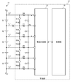
- FIG. 2 is a partial circuit diagram for explaining the abnormality diagnosis processing according to the first specific example.
- the power storage unit 11 is composed of five cells E1-E5 connected in series is shown.
- the voltage measuring unit 13 is connected to each node between the five cells E1 to E5 connected in series by a plurality of voltage measuring lines L0 to L5, and measures the voltage between two adjacent voltage measuring lines to measure each cell. Measure the voltage of E1-E5.
- Resistances R0-R5 are inserted in the plurality of voltage measurement lines L0-L5, respectively.
- a discharge circuit is connected between two adjacent voltage measurement lines of the plurality of voltage measurement lines L0-L5.
- Each discharge circuit is composed of a series circuit of a discharge switch S1d-S5d and a discharge resistor R1d-R5d.
- MOSFETs Metal Oxide Semiconductor Field Effect Transistor
- the discharge circuit is mainly used for equalizing the plurality of cells E1 to E5.
- Capacitors C1 to C5 are connected in parallel with the plurality of cells E1 to E5 between two adjacent voltage measurement lines of the plurality of voltage measurement lines L0 to L5.
- the capacitors C1-C5 play a role of stabilizing each potential of the plurality of voltage measuring lines L0-L5.
- the control unit 16 acquires the voltage values of the plurality of cells E1 to E5 from the voltage measurement unit 13. Signals are transmitted and received between the voltage measuring unit 13 and the control unit 16 by communication using an insulating interface, for example.
- the control unit 16 has an equalization processing function, and periodically performs equalization processing for a plurality of cells E1-E5. For example, the control unit 16 adjusts the voltage of the other plurality of cells to the voltage of the cell having the lowest voltage among the plurality of cells E1 to E5. Specifically, the control unit 16 turns on the discharge switches of the other plurality of cells to discharge the other plurality of cells. When the voltage of each of the other cells reaches the voltage of the cell having the lowest voltage, the control unit 16 turns off the discharge switch of each of the other cells.
- the control unit 16 executes the overvoltage (OV)/undervoltage (UV) detection process of the cell voltage as the first type of abnormality diagnosis process.
- the control unit 16 monitors each voltage of the plurality of cells E1 to E5.
- the control unit 16 compares the voltage of each cell with the OV threshold, and determines that the cell having a voltage higher than the OV threshold is overcharged.
- control unit 16 executes disconnection detection processing of a plurality of voltage measurement lines L0 to L5 as the second type abnormality diagnosis processing. In this process, it is diagnosed whether or not a break has occurred in any of the plurality of voltage measurement lines L0-L5.
- the control unit 16 turns on the plurality of discharge switches S1d-S5d at predetermined intervals. By the turn-on, the potentials of the plurality of voltage measurement lines L0-L5 converge on the potential of the lowest voltage measurement line L5 (for example, 0V).
- control unit 16 suspends the above-described cell voltage OV/UV detection processing while executing the disconnection detection processing of the plurality of voltage measurement lines L0 to L5.
- the control unit 16 turns on the plurality of discharge switches S1d-S5d, and then turns off the plurality of discharge switches S1d-S5d after a predetermined time has elapsed. Due to the turn-off, the potentials of the plurality of cells E1 to E5 measured by the voltage measuring unit 13 return to the states indicating the voltages of the plurality of cells E1 to E5. If a cell voltage after the turn-off of the plurality of discharge switches S1d-S5d does not recover to a voltage substantially equal to the cell voltage before the turn-on of the plurality of discharge switches S1d-S5d occurs, the control unit 16 determines that the cell It is determined that a disconnection has occurred in the voltage measurement line connected to. After turning off the plurality of discharge switches S1d-S5d, the control unit 16 restarts the above-described OV/UV detection processing of the cell voltage.
- FIG. 2 shows a state where the first voltage measurement line L1 is broken. Even if the first voltage measurement line L1 is broken, the voltages of the first cell E1 and the second cell E2 do not reach the OV threshold value/UV threshold value immediately and remain in the normal range for a certain period. The voltage of the first cell E1 and the second cell E2 does not reach the OV threshold value/UV threshold value immediately because the impedance between the 0th voltage measurement line L0 and the second voltage measurement line L2 above and below the disconnection point is balanced, This is because the charges in the first capacitor C1 and the second capacitor C2 do not immediately escape.
- the charge in the first capacitor C1 and the second capacitor C2 gradually escapes due to the wiring resistance in the voltage measuring unit 13, and the potential of the node Na between the first capacitor C1 and the second capacitor C2 gradually increases accordingly. descend. Finally, the voltage of the first cell E1 sticks to the upper limit value, and the voltage of the second cell E2 sticks to the lower limit value.
- a switch dedicated to disconnection detection may be provided separately from the plurality of discharge switches S1d-S5d between each of the plurality of voltage measurement lines L0-L5 and the ground potential.
- the control unit 16 does not use the plurality of discharge switches S1d-S5d, but uses the switch exclusively for detecting the disconnection to execute the disconnection detection process.
- FIG. 3 is a diagram showing a flowchart of a processing sequence according to a comparative example in the abnormality diagnosis process according to the specific example 1.
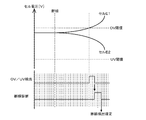
- FIG. 4 is a diagram showing an example of the voltage behavior of the first cell E1 and the second cell E when the processing sequence according to the comparative example is executed in the abnormality diagnosis processing according to the first specific example.
- the control unit 16 executes a plurality of abnormality diagnosis processes related to the voltages of the plurality of cells E1-En in parallel (S11).
- the control unit 16 executes the OV / UV detection process of the cell voltage and the disconnection detection process in parallel.
- the control unit 16 constantly executes the OV/UV detection processing of the cell voltage.
- the control unit 16 executes the disconnection detection process every predetermined time (for example, every 20 seconds). Note that the cell voltage OV/UV detection process is interrupted during the disconnection detection process.
- the control unit 16 may intermittently execute the OV / UV detection process of the cell voltage at a cycle shorter than the cycle of the disconnection detection process.
- the cell voltage OV/UV detection processing flag shown at the bottom of FIG. 4 indicates a state where no abnormality is detected when it is low, and indicates that an abnormality is detected when it is high.
- the disconnection detection processing flag indicates a state where the disconnection diagnosis is not being executed when the flag is low, and a state where the disconnection diagnosis is being executed when the flag is high.
- the control unit 16 determines the abnormality when the abnormal state continues for a specified time or longer. In the example illustrated in FIG. 4, the control unit 16 determines the OV of the cell voltage when the voltage of the first cell E1 continuously exceeds the OV threshold for a specified time or longer.
- the control unit 16 transmits a relay cut request to the vehicle ECU 30 via the vehicle-mounted network 20.
- the control unit 16 executes a fail-safe action corresponding to the disconnection of the voltage measurement line.
- the control unit 16 executes, for example, a transition to the degenerate mode as a fail-safe action corresponding to the disconnection of the voltage measurement line.
- the control unit 16 transmits an upper limit value change request for instructing to change the upper limit power value or the upper limit current value of the inverter 40 to a value lower than usual, via the vehicle-mounted network 20 to the vehicle ECU 30.
- vehicle ECU 30 Upon receiving the upper limit value change request, vehicle ECU 30 changes the upper limit power value or the upper limit current value of inverter 40 to the value in the degeneration mode.
- the upper limit value may be defined by the speed instead of the power value or the current value.
- the control unit 16 may limit the SOC usage range of the cell in the degenerate mode. For example, when the SOC usage range in the normal mode is 20 to 80%, the SOC usage range in the degenerate mode is limited to 40 to 60%.
- the control unit 16 transmits a relay cut request to the vehicle ECU 30 via the vehicle-mounted network 20. Yes (S15).
- the vehicle ECU 30 receives the relay cut request, it controls the relay R1 to be off (S16).
- the control unit 16 detects the disconnection of the voltage measurement line among the plurality of abnormality diagnosis processes related to the voltages of the plurality of cells E1 to En (N in S12, Y in S13)
- the alternative strategy of the voltage measurement line is detected.
- a fail safe action corresponding to the disconnection is executed (S14).
- the vehicle ECU 30 controls the relay R1 to be off (S16).
- the power of the electric vehicle 1 is turned off (OFF in step S10), the vehicle ECU 30 controls the relay R1 to be turned off (S16).
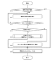
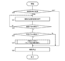
- FIG. 5 is a diagram showing a flowchart of the processing sequence according to the embodiment in the abnormality diagnosis process according to the specific example 1.
- FIG. 6 is a diagram showing an example of the voltage behavior of the first cell E1 and the second cell E when the processing sequence according to the embodiment is executed in the abnormality diagnosis process according to the specific example 1.
- the control unit 16 executes a plurality of abnormality diagnosis processes related to the voltages of the plurality of cells E1-En in parallel (S11). ..
- the control unit 16 detects the OV of the cell voltage.
- the control unit 16 uses the detection as a trigger to detect the disconnection which is the second type abnormality diagnosis processing. Perform processing immediately. That is, when an abnormality is detected in the OV / UV detection process of the cell voltage, the control unit 16 immediately executes the disconnection detection process regardless of the periodic execution timing of the disconnection detection process. The control unit 16 detects the disconnection of the first voltage measurement line L1 by executing the disconnection detection process.
- the control unit 16 When the disconnection is detected by the disconnection detection process, which is the second type of abnormality diagnosis process, the control unit 16 immediately executes a fail-safe action corresponding to the disconnection of the voltage measurement line.
- the control unit 16 detects the OV/UV of the cell voltage in the OV/UV detection process of the cell voltage, which is the first type of abnormality diagnosis process among the plurality of abnormality diagnosis processes related to the voltages of the plurality of cells E1 to En.
- the disconnection detection process which is the second type abnormality diagnosis process is executed (S13).
- the control unit 16 determines that the cause of the abnormality is the disconnection of the voltage measurement line, and responds to the disconnection of the voltage measurement line as an alternative strategy. Perform a fail-safe action (S14). When the process according to the alternative strategy ends, the vehicle ECU 30 controls the relay R1 to be off (S16). When the disconnection of the voltage measurement line is not detected by the disconnection detection process (N in S13), the control unit 16 determines that the cause of the abnormality is OV/UV of the cell voltage, and issues the relay cut request to the vehicle via the in-vehicle network 20. It is transmitted to the ECU 30 (S15). When the vehicle ECU 30 receives the relay cut request, it controls the relay R1 to be off (S16). When the power of the electric vehicle 1 is turned off (OFF in step S10), the vehicle ECU 30 controls the relay R1 to be turned off (S16).
- the control unit 16 immediately determines that the disconnection of the voltage measurement line has occurred, and degenerates. Switch to mode. In this case, it is not necessary to wait for the result of the cell voltage OV/UV detection processing, which is the first type abnormality diagnosis processing.
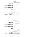
- FIG. 7 (a) and 7 (b) are diagrams comparing the processing sequence according to the comparative example and the processing sequence according to the example.
- FIG. 7A shows a processing sequence according to the comparative example
- FIG. 7B shows a processing sequence according to the embodiment.
- the relay cut is executed.
- the abnormality A is the cell voltage OV/UV
- the abnormality B is the disconnection of the voltage measurement line
- the abnormality that actually occurred is the disconnection of the voltage measurement line. Therefore, originally, it is necessary to shift to the degenerate mode as a fail-safe action. However, the relay cut is immediately made, and the electric vehicle 1 stops.
- the second type Abnormality diagnosis processing is executed immediately.
- the relay cut is not performed and the degeneration mode is entered.
- the second type abnormality diagnosis processing is executed by using it as a trigger.
- the cause of the abnormality can be correctly identified at an early stage. Therefore, it is possible to execute the correct fail-safe action according to the cause of the abnormality.
- an erroneous diagnosis of OV / UV of the cell voltage is made for the actually generated disconnection of the voltage measurement line, and the relay cut is executed based on the erroneous diagnosis.
- relay cut is executed to ensure the safety of the vehicle.
- HV hybrid vehicle
- PSV plug-in hybrid vehicle
- Specific Example 2 a processing sequence of the first type abnormality diagnosis processing and the second type abnormality diagnosis processing for detecting an abnormality related to the temperature control system of the plurality of cells E1-En will be described.
- the control unit 16 executes a malfunction detection process of the temperature control system of the heating system as the first type abnormality diagnosis process.
- the control unit 16 controls the heater 17 so that the temperature of the cell measured by a certain temperature sensor reaches the target temperature.
- the control unit 16 calculates the amount of heat required to bring the temperature of the cell to the target temperature from the deviation between the two, and determines the heating amount and heating time per unit time.
- the control unit 16 generates an expected temperature transition of the cell based on the determined heating amount and heating time per unit time. For example, when the temperature of the cell measured by the temperature sensor is 10°C and the target temperature is 25°C, the deviation is 15°C.
- the control unit 16 determines that the temperature control system of the heating system is malfunctioning when the difference between the temperature of the cell measured by the temperature sensor and the temperature on the expected temperature transition deviates by a predetermined set value or more.
- the malfunction of the temperature control system of the heating system may be caused by the failure of the heater 17 or the failure of the temperature sensor.
- the control unit 16 also executes the malfunction detection process of the temperature control system of the cooling system as the first type abnormality diagnosis process.
- the control unit 16 controls a fan, a cooler, or a water cooling system (not shown) so that the temperature of the cell measured by a certain temperature sensor reaches the target temperature.
- the control unit 16 calculates the amount of cooling required to bring the temperature of the cell to the target temperature from the deviation between the two, and determines the amount of cooling per unit time and the cooling time.
- the control unit 16 generates an expected temperature transition of the cell based on the determined cooling amount and cooling time per unit time. For example, when the temperature of the cell measured by the temperature sensor is 40° C. and the target temperature is 25° C., the deviation is 15° C.
- the control unit 16 determines that the temperature control system of the cooling system is malfunctioning when the difference between the temperature of the cell measured by the temperature sensor and the temperature on the expected temperature transition deviates by a predetermined set value or more.
- a cause of the malfunction of the temperature control system of the cooling system a failure of a fan, a cooler, or a water cooling system (not shown), a failure of the temperature sensor, or the like (not shown) can be considered.
- control unit 16 executes a characteristic deviation detection process of the temperature sensors T1-T3 as the second type abnormality diagnosis process.
- the characteristic shift is a state in which a shift exceeding a permissible value has occurred in the normal measurement range of the temperature sensor. Further, the characteristic deviation includes deviation exceeding the allowable value of the offset position.
- the control unit 16 determines that the temperature sensor has a characteristic deviation.
- the control unit 16 causes characteristic deviation in the temperature sensor whose output value deviates. It is determined that For example, a temperature sensor having an output value that deviates by a predetermined set value or more from the average value of the output values of the plurality of temperature sensors is determined to be a temperature sensor having a characteristic deviation. The control unit 16 executes this determination process every predetermined time.
- control unit 16 executes the output sticking detection process of the temperature sensors T1-T3 as the second type abnormality diagnosis process.
- the output sticking is a state in which the output value of the temperature sensor is stuck to the upper limit value or the lower limit value of the temperature sensor.
- FIG. 8 is a diagram showing a flowchart of a processing sequence according to a comparative example in the abnormality diagnosis process according to the specific example 2.
- the control unit 16 executes a plurality of abnormality diagnosis processes related to the temperature control system in parallel (S21).
- the controller 16 detects a malfunction of the temperature control system among the plurality of abnormality diagnosis processes (Y in S22), it stops the function of the temperature control system (S25).
- the control unit 16 detects a characteristic deviation of the temperature sensor among the plurality of abnormality diagnosis processing (N in S22, Y in S23), it executes a fail-safe action corresponding to the characteristic deviation of the temperature sensor as an alternative strategy. (S24).
- the output value of the temperature sensor having the characteristic deviation is replaced with the output value of the normal temperature sensor installed at the position closest to the temperature sensor.
- the control unit 16 identifies the output value of the normal temperature sensor whose behavior is closest to the output value of the temperature sensor in which the characteristic deviation occurs, and the difference between the two output values causes the characteristic deviation. It may be added to the output value of the temperature sensor.
- the control unit 16 stops the function of the temperature control system (S25).
- the control unit 16 stops the function of the temperature control system (S25).
- FIG. 9 is a diagram showing a flowchart of the processing sequence according to the embodiment in the abnormality diagnosis process according to the specific example 2.
- the control unit 16 executes a plurality of abnormality diagnosis processes related to the temperature control system in parallel (S11).
- the control unit 16 detects a malfunction of the temperature control system in the malfunction detection process of the temperature control system which is the first type malfunction diagnosis process among the plurality of malfunction diagnosis processes (Y in S22)
- the second A temperature sensor characteristic deviation detection process which is a type abnormality diagnosis process, is executed (S23). For example, the control unit 16 determines whether or not there is a temperature sensor whose output value greatly deviates from the output values of other temperature sensors among the plurality of temperature sensors.
- the control unit 16 determines that the characteristic shift has occurred in the specific temperature sensor.
- a fail-safe action corresponding to the characteristic deviation of the temperature sensor is executed (S24). For example, the control unit 16 replaces the output value of the temperature sensor having the characteristic deviation with the output value of the normal temperature sensor installed at the position closest to the temperature sensor.
- the control unit 16 stops the function of the temperature control system (S25).
- the control unit 16 determines that the temperature control system has malfunctioned, and the temperature control system functions. Is stopped (S25).
- the control unit 16 stops the function of the temperature control system (S25).
- the control unit 16 When the characteristic deviation of the temperature sensor is detected first by the characteristic deviation detection processing of the temperature sensor which is the second type of abnormality diagnosis processing, the control unit 16 immediately detects the temperature sensor in which the characteristic deviation occurs. The output value of is replaced with the output value of the normal temperature sensor installed at the position closest to the temperature sensor. In this case, it is not necessary to wait for the result of the malfunction detection process of the temperature control system which is the first type abnormality diagnosis process.
- the abnormality diagnosis processing of the second type is executed by using it as a trigger.
- the cause of the abnormality can be correctly identified at an early stage. Therefore, it is possible to execute the correct fail-safe action according to the cause of the abnormality.
- the malfunction of the temperature control system is diagnosed with respect to the abnormality of one temperature sensor, and the function of the temperature control system is stopped based on the diagnosis.
- the abnormality of one temperature sensor is a comparatively slight abnormality and can be replaced by the output value of another temperature sensor.
- the failure location can be specified as one temperature sensor, only the temperature sensor needs to be replaced, and the heater 17 and the fan need not be replaced.
- the specific example 1 has described a plurality of abnormality diagnosis processes related to the voltages of the plurality of cells E1 to En
- the specific example 2 has described a plurality of abnormality diagnosis processes related to the temperature control system.
- the first type abnormality diagnosis process includes a process of monitoring whether or not an overcurrent is flowing in the current path.
- the second type of abnormality diagnosis process includes a process of detecting a characteristic deviation of the current sensor.
- the control unit 16 executes, for example, a relay cut.
- the control unit 16 shifts to the degeneration mode, for example.
- the control unit 16 may execute the second abnormality diagnosis process only once after the power supply of the electric vehicle 1 is turned on, and then stop the second abnormality diagnosis process. Normally, the control unit 16 executes only the first type abnormality diagnosis process, and when an abnormality is detected by the first type abnormality diagnosis process, the control unit 16 executes the second abnormality diagnosis process by using it as a trigger. For example, in Specific Example 1, by not executing the disconnection detection process in the normal state, it is possible to eliminate the period during which the cell voltage cannot be measured. Further, the processing load of the control unit 16 can be reduced. On the other hand, in the example in which the first type abnormality diagnosis processing and the second type abnormality diagnosis processing are executed in parallel, redundancy is increased and robustness regarding abnormality detection is improved.
- the control unit 16 executes both the first type abnormality diagnosis process and the second type abnormality diagnosis process.
- the vehicle ECU 30 controls the cooler or the water cooling system. In this case, the vehicle ECU 30 and the control unit 16 of the power supply system 10 cooperate with each other to execute the failure diagnosis process.
- a control unit (16) that executes a plurality of abnormality diagnosis processes in the vehicle (1) is provided.
- the plurality of abnormality diagnosis processes include a first type abnormality diagnosis process that detects an abnormality that may occur due to a plurality of types of causes, and a second type abnormality diagnosis process that detects an abnormality that occurs due to one type of causes. Included, When an abnormality is detected by the first type abnormality diagnosis processing, the control unit (16) detects the abnormality by the first type abnormality diagnosis processing based on the diagnosis result of the second type abnormality diagnosis processing.
- An abnormality diagnosis system characterized by identifying the cause of an abnormality. According to this, the cause of the abnormality can be correctly identified.
- Item 2 Item 1 characterized in that, when an abnormality is detected by the first type abnormality diagnosis processing, the control unit (16) executes the second type abnormality diagnosis processing by using the detection of the abnormality as a trigger. Abnormality diagnosis system described in. According to this, the cause of the abnormality can be correctly identified at an early stage.
- the control unit (16) The second type of abnormality diagnosis processing is executed at predetermined time intervals, When an abnormality is detected by the first type abnormality diagnosis process, the abnormality detection process of the second type is triggered by the detection of the abnormality regardless of the periodic execution timing of the second type abnormality diagnosis process.
- the abnormality diagnosis system according to item 2, wherein the abnormality diagnosis system is executed.
- Item 7 The vehicle power supply system (1) according to Item 6, which is detected based on the voltage value of the voltage measurement line (L0-L5) at that time. According to this, it is possible to correctly detect whether or not the abnormality detected by the abnormality diagnosis processing of the first type is due to the disconnection of the voltage measurement lines (L0-L5).
Landscapes
- Engineering & Computer Science (AREA)
- General Physics & Mathematics (AREA)
- Physics & Mathematics (AREA)
- Chemical & Material Sciences (AREA)
- Power Engineering (AREA)
- General Chemical & Material Sciences (AREA)
- Electrochemistry (AREA)
- Chemical Kinetics & Catalysis (AREA)
- Mechanical Engineering (AREA)
- Manufacturing & Machinery (AREA)
- Life Sciences & Earth Sciences (AREA)
- Sustainable Development (AREA)
- Sustainable Energy (AREA)
- Transportation (AREA)
- Computing Systems (AREA)
- Health & Medical Sciences (AREA)
- General Health & Medical Sciences (AREA)
- Medical Informatics (AREA)
- Computer Networks & Wireless Communication (AREA)
- Signal Processing (AREA)
- Combustion & Propulsion (AREA)
- Electric Propulsion And Braking For Vehicles (AREA)
- Testing Of Short-Circuits, Discontinuities, Leakage, Or Incorrect Line Connections (AREA)
- Secondary Cells (AREA)
- Charge And Discharge Circuits For Batteries Or The Like (AREA)
Abstract
Description
車両(1)内において複数の異常診断処理を実行する制御部(16)を備え、
前記複数の異常診断処理には、複数の種類の原因により発生し得る異常を検出する第1タイプの異常診断処理と、1種類の原因により発生する異常を検出する第2タイプの異常診断処理が含まれ、
前記制御部(16)は、前記第1タイプの異常診断処理により異常が検出されたとき、前記第2タイプの異常診断処理の診断結果をもとに、前記第1タイプの異常診断処理により検出された異常の原因を特定することを特徴とする異常診断システム。
これによれば、異常の原因を正しく特定することができる。
[項目2]
前記制御部(16)は、前記第1タイプの異常診断処理により異常が検出されたとき、当該異常の検出をトリガとして、前記第2タイプの異常診断処理を実行することを特徴とする項目1に記載の異常診断システム。
これによれば、異常の原因を早期に正しく特定することができる。
[項目3]
前記制御部(16)は、
前記第2タイプの異常診断処理を所定時間毎に実行し、
前記第1タイプの異常診断処理により異常が検出されたとき、当該異常の検出をトリガとして、前記第2タイプの異常診断処理の周期的な実行タイミングに関係なく、前記第2タイプの異常診断処理を実行することを特徴とする項目2に記載の異常診断システム。
これによれば、第1タイプの異常診断処理と第2タイプの異常診断処理が並行して実行されている場合において、異常の原因を早期に正しく特定することができる。
[項目4]
前記制御部(16)は、前記第1タイプの異常診断処理を、継続的または前記第2タイプの異常診断処理の周期より短い周期で実行することを特徴とする項目3に記載の異常診断システム。
これによれば、異常の原因を誤って特定しやすい状況において、異常の原因を正しく特定することができる。
[項目5]
前記制御部(16)は、検出された異常の原因に応じて、異なるフェールセーフ処理を実行することを特徴とする項目1から4のいずれか1項に記載の異常診断システム。
これによれば、安全性と利便性を両立する最適なフェールセーフ処理を実行することができる。
[項目6]
直列接続された複数のセル(E1-En)と、
前記複数のセル(E1-En)間の各ノードと複数の電圧計測線(L0-L5)で接続され、隣接する電圧計測線間の電圧を計測して各セル(E1-En)の電圧を計測する電圧計測部(13)と、
項目1から5のいずれか1項に記載の異常診断システムと、を備え、
前記第1タイプの異常診断処理は、前記セル(E1-En)の過電圧または過小電圧を検出する処理を含み、
前記第2タイプの異常診断処理は、前記電圧計測線(L0-L5)の断線を検出する処理を含む、
ことを特徴とする車両用電源システム(1)。
これによれば、複数のセル(E1-En)の電圧に関連する異常の原因を正しく特定することができる。
[項目7]
前記複数の電圧計測線(L0-L5)を、所定の固定電位にそれぞれ接続させるための複数のスイッチ(S1d-S5d)をさらに備え、
前記制御部(16)は、
前記セル(E1-En)の過電圧または過小電圧を、前記電圧計測部(13)により計測される前記複数のセル(E1-En)の電圧値をもとに検出し、
前記電圧計測線(L0-L5)の断線を、当該電圧計測線(L0-L5)に接続されたスイッチ(S1d-S5d)をターンオンし、所定時間経過後に当該スイッチ(S1d-S5d)をターンオフしたときの当該電圧計測線(L0-L5)の電圧値をもとに検出することを特徴とする項目6に記載の車両用電源システム(1)。
これによれば、第1タイプの異常診断処理により検出された異常が、電圧計測線(L0-L5)の断線によるものか否かを正しく検出することができる。
Claims (7)
- 車両内において複数の異常診断処理を実行する制御部を備え、
前記複数の異常診断処理には、複数の種類の原因により発生し得る異常を検出する第1タイプの異常診断処理と、1種類の原因により発生する異常を検出する第2タイプの異常診断処理が含まれ、
前記制御部は、前記第1タイプの異常診断処理により異常が検出されたとき、前記第2タイプの異常診断処理の診断結果をもとに、前記第1タイプの異常診断処理により検出された異常の原因を特定することを特徴とする異常診断システム。 - 前記制御部は、前記第1タイプの異常診断処理により異常が検出されたとき、当該異常の検出をトリガとして、前記第2タイプの異常診断処理を実行することを特徴とする請求項1に記載の異常診断システム。
- 前記制御部は、
前記第2タイプの異常診断処理を所定時間毎に実行し、
前記第1タイプの異常診断処理により異常が検出されたとき、当該異常の検出をトリガとして、前記第2タイプの異常診断処理の周期的な実行タイミングに関係なく、前記第2タイプの異常診断処理を実行することを特徴とする請求項2に記載の異常診断システム。 - 前記制御部は、前記第1タイプの異常診断処理を、継続的または前記第2タイプの異常診断処理の周期より短い周期で実行することを特徴とする請求項3に記載の異常診断システム。
- 前記制御部は、検出された異常の原因に応じて、異なるフェールセーフ処理を実行することを特徴とする請求項1から4のいずれか1項に記載の異常診断システム。
- 直列接続された複数のセルと、
前記複数のセル間の各ノードと複数の電圧計測線で接続され、隣接する電圧計測線間の電圧を計測して各セルの電圧を計測する電圧計測部と、
請求項1から5のいずれか1項に記載の異常診断システムと、を備え、
前記第1タイプの異常診断処理は、前記セルの過電圧または過小電圧を検出する処理を含み、
前記第2タイプの異常診断処理は、前記電圧計測線の断線を検出する処理を含む、
ことを特徴とする車両用電源システム。 - 前記複数の電圧計測線を、所定の固定電位にそれぞれ接続させるための複数のスイッチをさらに備え、
前記制御部は、
前記セルの過電圧または過小電圧を、前記電圧計測部により計測される前記複数のセルの電圧値をもとに検出し、
前記電圧計測線の断線を、当該電圧計測線に接続されたスイッチをターンオンし、所定時間経過後に当該スイッチをターンオフしたときの当該電圧計測線の電圧値をもとに検出することを特徴とする請求項6に記載の車両用電源システム。
Priority Applications (3)
| Application Number | Priority Date | Filing Date | Title |
|---|---|---|---|
| JP2021503423A JP7301121B2 (ja) | 2019-03-06 | 2019-12-19 | 異常診断システム、及び車両用電源システム |
| CN201980093659.7A CN113544896B (zh) | 2019-03-06 | 2019-12-19 | 异常诊断系统和车辆用电源系统 |
| US17/434,478 US12403771B2 (en) | 2019-03-06 | 2019-12-19 | Abnormality diagnosing system, and power supply system for vehicle |
Applications Claiming Priority (2)
| Application Number | Priority Date | Filing Date | Title |
|---|---|---|---|
| JP2019040507 | 2019-03-06 | ||
| JP2019-040507 | 2019-03-06 |
Publications (1)
| Publication Number | Publication Date |
|---|---|
| WO2020179192A1 true WO2020179192A1 (ja) | 2020-09-10 |
Family
ID=72338558
Family Applications (1)
| Application Number | Title | Priority Date | Filing Date |
|---|---|---|---|
| PCT/JP2019/049757 Ceased WO2020179192A1 (ja) | 2019-03-06 | 2019-12-19 | 異常診断システム、及び車両用電源システム |
Country Status (4)
| Country | Link |
|---|---|
| US (1) | US12403771B2 (ja) |
| JP (1) | JP7301121B2 (ja) |
| CN (1) | CN113544896B (ja) |
| WO (1) | WO2020179192A1 (ja) |
Cited By (4)
| Publication number | Priority date | Publication date | Assignee | Title |
|---|---|---|---|---|
| WO2023030728A1 (de) * | 2021-08-31 | 2023-03-09 | Robert Bosch Gmbh | Verfahren zum betreiben einer schaltvorrichtung, schaltvorrichtung, elektrischer energiespeicher und vorrichtung |
| JP2023121434A (ja) * | 2022-02-21 | 2023-08-31 | 西日本旅客鉄道株式会社 | 車両状態判定システム |
| JP2024101526A (ja) * | 2023-01-17 | 2024-07-29 | 廣達電腦股▲ふん▼有限公司 | スマートバッテリー温度補償方法 |
| WO2024224909A1 (ja) * | 2023-04-26 | 2024-10-31 | パナソニックIpマネジメント株式会社 | 異常検知装置および電池システム |
Families Citing this family (3)
| Publication number | Priority date | Publication date | Assignee | Title |
|---|---|---|---|---|
| CN113985118B (zh) * | 2021-10-29 | 2024-11-22 | 东风汽车有限公司东风日产乘用车公司 | 车载电流故障检测装置 |
| CN114895187B (zh) * | 2022-04-24 | 2025-09-02 | 深圳市拓邦锂电池有限公司 | 一种电池管理系统及其电压温度检测方法、电子装置 |
| CN120792597B (zh) * | 2025-08-04 | 2026-03-06 | 齐鲁工业大学(山东省科学院) | 房车大容量电池安全管理方法及系统 |
Citations (3)
| Publication number | Priority date | Publication date | Assignee | Title |
|---|---|---|---|---|
| JP2008157808A (ja) * | 2006-12-25 | 2008-07-10 | Toshiba Corp | 組電池システム |
| JP2010011722A (ja) * | 2007-11-21 | 2010-01-14 | Denso Corp | 組電池の異常検出装置 |
| WO2011037257A1 (ja) * | 2009-09-28 | 2011-03-31 | 日立ビークルエナジー株式会社 | 電池システム |
Family Cites Families (13)
| Publication number | Priority date | Publication date | Assignee | Title |
|---|---|---|---|---|
| JPH0787602A (ja) * | 1993-09-17 | 1995-03-31 | Matsushita Electric Ind Co Ltd | 電気自動車の保護装置 |
| JP4019815B2 (ja) * | 2002-06-26 | 2007-12-12 | 日産自動車株式会社 | 組電池の異常診断装置および方法 |
| JP4186916B2 (ja) * | 2004-11-18 | 2008-11-26 | 株式会社デンソー | 組電池管理装置 |
| JP5965017B2 (ja) * | 2013-03-18 | 2016-08-03 | 株式会社日立製作所 | 電池システムおよび電池監視装置 |
| WO2010089843A1 (ja) * | 2009-02-03 | 2010-08-12 | トヨタ自動車株式会社 | 車両の充電システムおよび充電システムの制御方法 |
| JP5133926B2 (ja) * | 2009-03-26 | 2013-01-30 | 株式会社日立製作所 | 車両用電池システム |
| JP5932569B2 (ja) * | 2012-08-24 | 2016-06-08 | ルネサスエレクトロニクス株式会社 | 半導体装置及び電池電圧監視装置 |
| JP6302727B2 (ja) * | 2014-04-10 | 2018-03-28 | 日立オートモティブシステムズ株式会社 | 電動モータの制御装置 |
| WO2015181866A1 (ja) * | 2014-05-26 | 2015-12-03 | 株式会社日立製作所 | 電池システム |
| JPWO2017159218A1 (ja) | 2016-03-15 | 2019-01-24 | 三洋電機株式会社 | 管理装置および電源装置 |
| JP2018057123A (ja) | 2016-09-28 | 2018-04-05 | 株式会社ケーヒン | バッテリ監視装置 |
| JP6527561B2 (ja) * | 2017-08-10 | 2019-06-05 | 株式会社Subaru | 車両用制御装置 |
| JP6958439B2 (ja) * | 2018-03-08 | 2021-11-02 | トヨタ自動車株式会社 | 電動車両及び電動車両の制御方法 |
-
2019
- 2019-12-19 JP JP2021503423A patent/JP7301121B2/ja active Active
- 2019-12-19 US US17/434,478 patent/US12403771B2/en active Active
- 2019-12-19 CN CN201980093659.7A patent/CN113544896B/zh active Active
- 2019-12-19 WO PCT/JP2019/049757 patent/WO2020179192A1/ja not_active Ceased
Patent Citations (3)
| Publication number | Priority date | Publication date | Assignee | Title |
|---|---|---|---|---|
| JP2008157808A (ja) * | 2006-12-25 | 2008-07-10 | Toshiba Corp | 組電池システム |
| JP2010011722A (ja) * | 2007-11-21 | 2010-01-14 | Denso Corp | 組電池の異常検出装置 |
| WO2011037257A1 (ja) * | 2009-09-28 | 2011-03-31 | 日立ビークルエナジー株式会社 | 電池システム |
Cited By (6)
| Publication number | Priority date | Publication date | Assignee | Title |
|---|---|---|---|---|
| WO2023030728A1 (de) * | 2021-08-31 | 2023-03-09 | Robert Bosch Gmbh | Verfahren zum betreiben einer schaltvorrichtung, schaltvorrichtung, elektrischer energiespeicher und vorrichtung |
| JP2023121434A (ja) * | 2022-02-21 | 2023-08-31 | 西日本旅客鉄道株式会社 | 車両状態判定システム |
| JP7795170B2 (ja) | 2022-02-21 | 2026-01-07 | 西日本旅客鉄道株式会社 | 車両状態判定システム |
| JP2024101526A (ja) * | 2023-01-17 | 2024-07-29 | 廣達電腦股▲ふん▼有限公司 | スマートバッテリー温度補償方法 |
| JP7659022B2 (ja) | 2023-01-17 | 2025-04-08 | 廣達電腦股▲ふん▼有限公司 | スマートバッテリー温度補償方法 |
| WO2024224909A1 (ja) * | 2023-04-26 | 2024-10-31 | パナソニックIpマネジメント株式会社 | 異常検知装置および電池システム |
Also Published As
| Publication number | Publication date |
|---|---|
| US20220134886A1 (en) | 2022-05-05 |
| CN113544896A (zh) | 2021-10-22 |
| JPWO2020179192A1 (ja) | 2020-09-10 |
| JP7301121B2 (ja) | 2023-06-30 |
| US12403771B2 (en) | 2025-09-02 |
| CN113544896B (zh) | 2024-06-28 |
Similar Documents
| Publication | Publication Date | Title |
|---|---|---|
| JP7301121B2 (ja) | 異常診断システム、及び車両用電源システム | |
| US11554687B2 (en) | Power supply system and management device capable of determining current upper limit for supressing cell deterioration and ensuring safety | |
| JP6595063B2 (ja) | 電池システム監視装置 | |
| US9746525B2 (en) | Battery system monitoring device | |
| JP5647210B2 (ja) | 電池セル用集積回路 | |
| EP3564688B1 (en) | Ground fault detection apparatus | |
| US9590432B2 (en) | Battery control device comprising a plurality of cell controllers and being capable of determining whether a cell controller is operating abnormally | |
| CN114103838A (zh) | 用于自主车辆的电力控制设备和方法 | |
| KR101326508B1 (ko) | 고전압 배터리시스템 전류센서의 고장진단방법 | |
| US20170373512A1 (en) | First Series Then Parallel Battery Pack System | |
| CN106066463B (zh) | 诊断环保型车辆电池系统的电流传感器故障的设备和方法 | |
| US9840157B2 (en) | Battery management system and battery system | |
| JP6504855B2 (ja) | 劣化検出装置および劣化検出方法 | |
| JP2006262642A (ja) | 電源システムの監視装置 | |
| JP6663039B2 (ja) | バッテリー保護システムおよび方法 | |
| CN107870284A (zh) | 电压检测装置 | |
| KR101854456B1 (ko) | 배터리 센서 및 배터리 모니터링 시스템 | |
| JP2020046334A (ja) | バッテリ監視装置 | |
| JP6602800B2 (ja) | 組電池電圧測定装置及び電池制御装置 | |
| CN117897629A (zh) | 用于对能量系统中的电流测量进行核实的方法 |
Legal Events
| Date | Code | Title | Description |
|---|---|---|---|
| 121 | Ep: the epo has been informed by wipo that ep was designated in this application |
Ref document number: 19918489 Country of ref document: EP Kind code of ref document: A1 |
|
| ENP | Entry into the national phase |
Ref document number: 2021503423 Country of ref document: JP Kind code of ref document: A |
|
| NENP | Non-entry into the national phase |
Ref country code: DE |
|
| 122 | Ep: pct application non-entry in european phase |
Ref document number: 19918489 Country of ref document: EP Kind code of ref document: A1 |
|
| WWG | Wipo information: grant in national office |
Ref document number: 17434478 Country of ref document: US |