WO2020179113A1 - 点火器組立体、及び保持部の成形方法 - Google Patents
点火器組立体、及び保持部の成形方法 Download PDFInfo
- Publication number
- WO2020179113A1 WO2020179113A1 PCT/JP2019/037959 JP2019037959W WO2020179113A1 WO 2020179113 A1 WO2020179113 A1 WO 2020179113A1 JP 2019037959 W JP2019037959 W JP 2019037959W WO 2020179113 A1 WO2020179113 A1 WO 2020179113A1
- Authority
- WO
- WIPO (PCT)
- Prior art keywords
- igniter
- wall
- resin material
- surrounding wall
- igniter assembly
- Prior art date
- Legal status (The legal status is an assumption and is not a legal conclusion. Google has not performed a legal analysis and makes no representation as to the accuracy of the status listed.)
- Ceased
Links
Images





Classifications
-
- B—PERFORMING OPERATIONS; TRANSPORTING
- B60—VEHICLES IN GENERAL
- B60R—VEHICLES, VEHICLE FITTINGS, OR VEHICLE PARTS, NOT OTHERWISE PROVIDED FOR
- B60R21/00—Arrangements or fittings on vehicles for protecting or preventing injuries to occupants or pedestrians in case of accidents or other traffic risks
- B60R21/02—Occupant safety arrangements or fittings, e.g. crash pads
- B60R21/16—Inflatable occupant restraints or confinements designed to inflate upon impact or impending impact, e.g. air bags
- B60R21/26—Inflatable occupant restraints or confinements designed to inflate upon impact or impending impact, e.g. air bags characterised by the inflation fluid source or means to control inflation fluid flow
- B60R21/264—Inflatable occupant restraints or confinements designed to inflate upon impact or impending impact, e.g. air bags characterised by the inflation fluid source or means to control inflation fluid flow using instantaneous generation of gas, e.g. pyrotechnic
- B60R21/2644—Inflatable occupant restraints or confinements designed to inflate upon impact or impending impact, e.g. air bags characterised by the inflation fluid source or means to control inflation fluid flow using instantaneous generation of gas, e.g. pyrotechnic using only solid reacting substances, e.g. pellets, powder
-
- B—PERFORMING OPERATIONS; TRANSPORTING
- B60—VEHICLES IN GENERAL
- B60R—VEHICLES, VEHICLE FITTINGS, OR VEHICLE PARTS, NOT OTHERWISE PROVIDED FOR
- B60R21/00—Arrangements or fittings on vehicles for protecting or preventing injuries to occupants or pedestrians in case of accidents or other traffic risks
- B60R21/02—Occupant safety arrangements or fittings, e.g. crash pads
- B60R21/16—Inflatable occupant restraints or confinements designed to inflate upon impact or impending impact, e.g. air bags
- B60R21/26—Inflatable occupant restraints or confinements designed to inflate upon impact or impending impact, e.g. air bags characterised by the inflation fluid source or means to control inflation fluid flow
- B60R2021/26029—Ignitors
-
- B—PERFORMING OPERATIONS; TRANSPORTING
- B60—VEHICLES IN GENERAL
- B60R—VEHICLES, VEHICLE FITTINGS, OR VEHICLE PARTS, NOT OTHERWISE PROVIDED FOR
- B60R21/00—Arrangements or fittings on vehicles for protecting or preventing injuries to occupants or pedestrians in case of accidents or other traffic risks
- B60R21/02—Occupant safety arrangements or fittings, e.g. crash pads
- B60R21/16—Inflatable occupant restraints or confinements designed to inflate upon impact or impending impact, e.g. air bags
- B60R21/26—Inflatable occupant restraints or confinements designed to inflate upon impact or impending impact, e.g. air bags characterised by the inflation fluid source or means to control inflation fluid flow
- B60R2021/26029—Ignitors
- B60R2021/26041—Ignitors of elongated shape
-
- B—PERFORMING OPERATIONS; TRANSPORTING
- B60—VEHICLES IN GENERAL
- B60R—VEHICLES, VEHICLE FITTINGS, OR VEHICLE PARTS, NOT OTHERWISE PROVIDED FOR
- B60R21/00—Arrangements or fittings on vehicles for protecting or preventing injuries to occupants or pedestrians in case of accidents or other traffic risks
- B60R21/02—Occupant safety arrangements or fittings, e.g. crash pads
- B60R21/16—Inflatable occupant restraints or confinements designed to inflate upon impact or impending impact, e.g. air bags
- B60R21/26—Inflatable occupant restraints or confinements designed to inflate upon impact or impending impact, e.g. air bags characterised by the inflation fluid source or means to control inflation fluid flow
- B60R21/264—Inflatable occupant restraints or confinements designed to inflate upon impact or impending impact, e.g. air bags characterised by the inflation fluid source or means to control inflation fluid flow using instantaneous generation of gas, e.g. pyrotechnic
- B60R21/2644—Inflatable occupant restraints or confinements designed to inflate upon impact or impending impact, e.g. air bags characterised by the inflation fluid source or means to control inflation fluid flow using instantaneous generation of gas, e.g. pyrotechnic using only solid reacting substances, e.g. pellets, powder
- B60R2021/2648—Inflatable occupant restraints or confinements designed to inflate upon impact or impending impact, e.g. air bags characterised by the inflation fluid source or means to control inflation fluid flow using instantaneous generation of gas, e.g. pyrotechnic using only solid reacting substances, e.g. pellets, powder comprising a plurality of combustion chambers or sub-chambers
Definitions
- the present invention relates to an igniter assembly in a gas generator and a method for forming a holding portion in the igniter assembly.
- an igniter has been widely used as a starting device for a gas generator for an airbag.
- a method is known in which the igniter is fixed to a collar attached to the housing side via a holding portion made of a resin material.
- a gas generator is disclosed (for example, Patent Document 1).
- the igniter when the gas generator is in operation, the igniter operates to explode the metal cup containing the igniting charge for igniting the combustion agent, thereby releasing the flame.
- the holding part When a structure is used in which the igniter is fixed to the collar via a holding part made of a resin material, the holding part is deformed by the load acting on the holding part when the igniter is activated, and the igniter and the collar are fixed in the holding part. Cracks or breakage may occur in the part to be etched. In such a case, depending on the state of cracks or breakage, the holding of the igniter may be insufficient and the igniter may be lifted from the holding portion, or the sealing property as a gas generator may be impaired.
- the technique disclosed in the present application has been made in view of the above-described problems, and when operating the igniter, it is possible to suppress a defect caused by cracks or damages in a holding portion for fixing the igniter to the collar. It is intended to provide an assembly.
- the igniter assembly disclosed in the present application includes an igniter including a storage space that stores an ignition charge for igniting a combustion agent, a collar that supports the igniter, and the igniter fixed to the collar. And a holding portion formed of a resin material, the igniter having a cylindrical peripheral wall and a lid wall closing one end of the peripheral wall, and the lid wall operating the igniter.
- the cup body is arranged so as to be positioned on the discharge direction side of the combustion products of the ignition charge, and the opening formed at the other end of the cup body is closed, the cup body is accommodated together with the cup body.
- a closing portion that defines a space, wherein the peripheral wall is a contact region that is in contact with the closing portion in an axial direction of the peripheral wall, and a region closer to the lid wall than the contact region is the closing portion.
- a non-contact region that does not contact with, the holding unit is formed continuously with the base unit that covers the periphery of the contact region to fix the igniter to the collar.
- An annular surrounding wall configured to surround the non-contact area to suppress the combustion agent from being arranged around the non-contact area, and the base in the holding portion.
- the igniter operates between a first portion including at least a part of the portion and a second portion including the tip of the surrounding wall, which is closer to the discharge direction than the first portion.
- the surrounding wall formed in the holding portion suppresses the placement of the combustion agent around the non-contact region. That is, if the surrounding wall does not exist, a space is formed around the cup body protruding from the upper end surface of the collar toward the lid wall side.
- the combustion agent is arranged around the non-contact region during operation of the igniter, the combustion agent is located at a position deviated from the emission direction of the combustion products with respect to the igniter. Become. As a result, the combustion agent may not be sufficiently combusted, and the combustion residue or combustion delay of the combustion agent may occur.
- the igniter assembly disclosed in the present application it is possible to prevent the combustion agent from being disposed around the non-contact region, and thus to suppress the occurrence of combustion residue or combustion delay of the combustion agent after the operation of the igniter. be able to. As a result, the output performance of the gas generator can be improved. Further, since the surrounding wall plays a role of a cushion for the combustion agent, it is possible to prevent the combustion agent from rattling after the gas generator is assembled, and to easily assemble the gas generator.
- the second portion when the surrounding wall is loaded by the operation of the igniter, the second portion preferentially moves outward in the radial direction as compared with the first portion.
- a fragile portion is formed so as to be deformed.
- the energy due to the load applied to the surrounding wall is likely to be consumed in the deformation of the second portion, so that the large deformation of the first portion is suppressed.
- the first portion is a portion including at least a part of the base portion for fixing the igniter to the collar, by suppressing the occurrence of cracks and breakage in the first portion, the igniter It is possible to suppress the occurrence of problems such as floating and deterioration of sealing performance.
- the combustion agent disclosed in the present application includes a gas generator that generates combustion gas for inflating the airbag and a fire-transmitting agent for burning the gas generator. Further, the deformation of the second portion may be accompanied by fracture or breakage, and the second portion may be separated from the first portion by ductile fracture or brittle fracture.
- the above-mentioned weak portion may be formed as follows. That is, in the igniter assembly, the surrounding wall has a thick portion and a thin portion that extends along the circumferential direction and has a radial thickness that is thinner than the thick portion. May be formed as the thin portion.
- the stress generated in the holding portion due to the load applied to the surrounding wall when the igniter is operated can be concentrated on the thin-walled portion, and the second portion can be deformed preferentially over the first portion.
- a groove portion that extends along the circumferential direction of the surrounding wall and is recessed in the radial direction is formed in the surrounding wall so that the thin wall portion is formed. Parts may be formed. According to this, since the siege wall is formed with a groove, when a load is applied to the siege wall, the siege wall is easily deformed so as to fall outward in the radial direction. As a result, it is possible to make it easier to preferentially deform the second portion than the first portion.
- the groove may be formed on either the inner peripheral surface or the outer peripheral surface of the surrounding wall.
- the depth in the radial direction from the outer peripheral surface of the thick portion to the bottom portion of the groove portion is in the radial direction of the thick portion. It is preferably 1/3 or more and 3/4 or less of the thickness. By doing so, it becomes easy to preferentially deform the second portion over the first portion.
- the above-mentioned weak portion may be formed as follows. That is, in the igniter assembly, the first portion is formed of the first resin material, the second portion is formed of the second resin material having a later curing time than the first resin material, and the fragile portion is formed.
- the part may be formed as an interface between the first part and the second part.
- the first resin material forming the first portion and the second resin material forming the second portion are set at different curing times to form an interface between the first portion and the second portion. doing.
- the curing time can be regarded as the molding time.
- the first portion is injection-molded with the first resin material first, and after curing, injection-molded with the second resin material from above.
- the stress generated in the holding portion due to the load applied to the surrounding wall when the igniter is activated can be concentrated on the interface.
- the second portion can be preferentially deformed outward in the radial direction more easily than the first portion.
- the holding portion when the weak portion is formed as the interface between the first portion and the second portion, the holding portion may be formed by the following forming method. That is, the method for molding the holding portion disclosed in the present application is that the first resin material is melted and cured to mold the first portion, and after the first resin material is cured, Molding the second portion by melting and curing the second resin material may be included.
- the first resin material when the weak portion is formed at the interface between the first portion and the second portion, the first resin material has a higher melting point than the second resin material. Good.
- the second portion it is possible to prevent the cured first resin material from melting when the second resin material in the molten state is poured.
- an interface between the first resin material and the second resin material can be formed, and deformation of the first portion due to melting of the first resin material can be suppressed.
- the above-mentioned first resin material and the second resin material may be the same type of resin material or different types of resin material.
- the surrounding wall may form an annular gap with the non-contact region of the peripheral wall, and the size of the gap may be smaller than the size of the combustion agent. According to this, the impact applied from the cup body to the surrounding wall when the igniter is activated can be buffered by the gap. Further, by making the size of the gap smaller than the size of the combustion agent, it is possible to prevent the combustion agent from entering the gap.
- the surrounding wall is formed by a plurality of intermittent walls arranged in a ring shape at predetermined intervals in the circumferential direction, and the predetermined interval is formed smaller than the size of the combustion agent. May be done. According to this, since the surrounding wall is formed by a plurality of intermittent walls, the cross-sectional area in the cross section orthogonal to the axial direction of each intermittent wall can be reduced. Thereby, each interrupted wall can be easily deformed. As a result, when a load is applied to the surrounding wall, the second portion can be easily deformed so as to be separated from the igniter preferentially over the first portion.
- the predetermined interval smaller than the size of the combustion agent, it is possible to prevent the combustion agent from entering the gap formed between the adjacent interrupted walls. Further, when the surrounding wall is formed by a plurality of interrupted walls, the second portion can be further easily deformed by setting the predetermined interval shorter than the length of one interrupted wall in the circumferential direction.
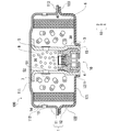
- FIG. 1 is an axial cross-sectional view of a gas generator for an airbag using the igniter assembly according to the first embodiment.
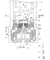
- FIG. 2 is a diagram showing the structure of the igniter assembly according to the first embodiment.
- FIG. 3 is a first diagram for explaining a state when the igniter operates and the cup body bursts in the igniter assembly according to the first embodiment.
- FIG. 4 is a second diagram for explaining a state when the igniter operates and the cup body bursts in the igniter assembly according to the first embodiment.
- FIG. 5 is a third diagram for explaining a state when the igniter operates and the cup body bursts in the igniter assembly according to the first embodiment.
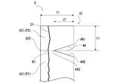
- FIG. 6 is a first diagram showing the mode of the crack when the second portion of the igniter assembly according to the first embodiment is cracked.
- FIG. 7 is a second view showing the mode of the crack when the second portion of the igniter assembly according to the first embodiment is cracked.
- FIG. 8 is a top view of the igniter assembly according to the first modification of the first embodiment.
- FIG. 9 is a figure which shows the structure of the igniter assembly which concerns on the modification 2 of 1st Embodiment.
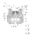
- FIG. 10 is a diagram showing a structure near the igniter assembly according to the second embodiment.
- FIG. 11 is a figure which shows the process of the shaping
- FIG. 12 is a view for explaining a state when the igniter operates and the cup body bursts in the igniter assembly according to the second embodiment.
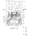
- FIG. 1 is an axial sectional view of an airbag gas generator (hereinafter, gas generator) 100 using the igniter assembly 10 according to the first embodiment disclosed in the present application.
- the gas generator 100 includes a housing 1, an igniter 2, a collar 3, a holding portion 4, an inner cylinder 5, and a coolant filter 6.
- the igniter 2, the collar 3, the holding portion 4, the inner cylinder 5, and the coolant/filter 6 are arranged in the internal space of the housing 1.
- the configuration including the igniter 2, the collar 3, and the holding portion 4 is referred to as an igniter assembly 10.
- the gas generator 100 burns the gas generating agent 7 filled in the housing 1 by operating the igniter 2 and releases the combustion gas, which is a combustible product, to the outside of the housing 1 to thereby generate an airbag. It is configured to inflate (not shown).
- each configuration of the gas generator 100 will be described.
- both ends in the axial direction are closed by joining a metal upper shell 11 and a lower shell 12 each formed in a substantially cylindrical shape with a bottom with their open ends facing each other. It is formed in a short cylindrical shape.
- the direction along the axial direction of the housing 1 is defined as the vertical direction of the gas generator 100, the upper shell 11 side (that is, the upper side in FIG. 1) is the upper side of the gas generator 100, and the lower shell 12 side (that is, the upper side).
- the lower side in FIG. 1) is the lower side of the gas generator 100.
- the upper shell 11 includes a substantially disc-shaped top plate portion 111, an outer peripheral wall portion 112 extending downward from a peripheral edge of the top plate portion 111, and a flange portion extending radially outward from a tip end portion of the outer peripheral wall portion 112. And 113.
- the lower shell 12 includes a substantially disc-shaped bottom plate portion 121, an outer peripheral wall portion 122 that extends upward from a peripheral edge of the bottom plate portion 121, and a flange portion that extends radially outward from a tip end portion of the outer peripheral wall portion 122. 123 and.
- Such an upper shell 11 and a lower shell 12 are formed by pressing a stainless steel plate.
- the upper shell 11 and the lower shell 12 form a housing 1 by superimposing the flange portion 113 and the flange portion 123 and joining them by laser welding or the like.
- a plurality of gas ejection ports 13 are formed side by side in the circumferential direction on the outer peripheral wall 112 of the upper shell 11.
- the gas ejection port 13 is closed by a sealing tape 14.
- As the seal tape 14 an aluminum foil or the like having one surface coated with an adhesive member is used. Thereby, the airtightness of the housing 1 is ensured.
- an opening cylinder portion 1211 projecting downward is provided at the center of the bottom plate portion 121 of the lower shell 12.
- the inner wall of the opening tubular portion 1211 forms an opening 15 that communicates the internal space of the housing 1 with the external space.
- the inner cylinder 5 has a tubular shape with both ends open, and is arranged in a posture in which the central axis coincides with the vertical direction (that is, the axial direction of the housing 1).
- the inner cylinder 5 is formed of a stainless steel pipe. As shown in FIG. 1, the lower end of the inner cylinder 5 is fitted into the opening 15, and the outer peripheral surface of the inner cylinder 5 is in contact with the inner peripheral surface of the opening 15 at the lower end. Further, the upper end of the inner cylinder 5 is in contact with the top plate portion 111 of the upper shell 11. As a result, the internal space of the housing 1 is divided in the radial direction by the inner cylinder 5.
- the inside of the inner cylinder 5 defines a cylindrical firebox 20 in which the igniter assembly 10 is arranged and the firebox 8 as a combustion agent is filled, and the inner cylinder
- the outside of 5 defines an annular combustion chamber 30 filled with the gas generating agent 7.
- the inner cylinder 5 is formed with a plurality of fire transmission holes 51, which are holes for communicating the fire transmission chamber 20 and the combustion chamber 30, arranged side by side in the circumferential direction.
- the fire transmission hole 51 is closed by the sealing tape 52.
- the inner cylinder 5 and the housing 1 are joined by being welded, for example, at a portion where they come into contact with each other.
- the coolant/filter 6 is annularly arranged in the combustion chamber 30 so as to surround the gas generating agent 7, and defines an annular gap 40 between the outer peripheral wall 112 and the outer peripheral wall 122 of the housing 1.
- the coolant filter 6 is formed by stacking stainless steel flat braided wire meshes in the radial direction and compressing them in the radial direction and the axial direction.
- a predetermined signal is sent to the igniter 2 to activate the igniter 2 and the transfer charge 8 in the transfer chamber 20.
- Ignite The combustion of the transfer charge 8 produces a high-temperature flame in the transfer chamber 20. This flame breaks the seal tape 52 and is ejected from the flame transfer hole 51 into the combustion chamber 30 to ignite the gas generating agent 7. Then, the combustion of the gas generating agent 7 produces high-temperature and high-pressure gas, and this combustion gas passes through the entire area of the coolant/filter 6. At this time, the coolant/filter 6 cools the combustion gas generated in the combustion chamber 30 and collects the combustion residue.
- the combustion gas cooled and purified by the coolant filter 6 passes through the gap 40, breaks the sealing tape 14, is ejected from the gas outlet 13, and flows into an airbag (not shown).
- an airbag (not shown).
- the gas generator 7 for example, a single-hole columnar one composed of guanidine nitrate (41% by weight), basic copper nitrate (49% by weight), a binder and additives can be used.
- the transfer charge 8 for example, one made of nitroguanidine (34% by weight) and strontium nitrate (56% by weight) can be used.
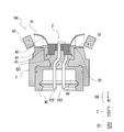
- FIG. 2 is a diagram showing a structure of an igniter assembly 10 according to the first embodiment.
- the igniter assembly 10 includes an igniter 2 including an ignition chamber 50 as a storage space for storing an ignition charge (not shown) for igniting the transfer charge 8, a collar 3 for supporting the igniter 2, and a collar 3.
- the igniter 2 burns the ignition charge in the ignition chamber 50 by the ignition current supplied from the outside of the transfer chamber 20.
- the igniter 2 is fixed to the lower part of the firebox 20 by the holding portion 4.
- the ignition charge is burned, the combustion product is released upward, and the transfer charge 8 is ignited.
- the direction in which the combustion products are released from the igniter 2 (upward in this example) may be referred to as the release direction.
- the igniter 2 is arranged so as to close a cup body 21 having one end closed and the other end open, and an opening formed at the other end of the cup body 21 to ignite with the cup body 21.
- a closure 22 defining a chamber 50.
- the cup body 21 is formed in a cup shape by a cylindrical peripheral wall 211 and a lid wall 212 that closes one end of the peripheral wall 211.
- the peripheral wall 211 is arranged so that its central axis coincides with the vertical direction.
- the lid wall 212 is continuously formed on the peripheral wall 211, and forms the upper wall of the ignition chamber 50 by closing the upper end portion of the peripheral wall 211.
- the cup body 21 is arranged such that the lid wall 212 is positioned on the discharge direction side of the combustion products of the ignition charge when the igniter 2 is operating.
- the cup body 21 has a double structure in which a metal inner cup and a resin outer cup are stacked. However, the material of the cup body 21 is not limited to this.
- the closing portion 22 has a metal header 221 arranged at the lower end of the peripheral wall 211, and a pair of energizing pins 222 and 222 extending downward from the metal header 221.
- the metal header 221 is formed of a metal material in a substantially columnar shape, and is in contact with the peripheral wall 211 on the outer peripheral surface thereof.
- a through hole that penetrates vertically is formed in the central portion of the metal header 221.
- One of the pair of energizing pins 222 and 222 is joined to the metal header 221 via an insulator while being inserted into the through hole of the metal header 221.
- a bridge wire 23, which is a resistor for electrically connecting the energizing pin 222 and the metal header 221, is wired at the bottom of the ignition chamber 50.
- the other of the pair of energizing pins 222 and 222 is joined to the lower surface of the metal header 221.
- the closing portion 22 forms a lower wall of the ignition chamber 50 by closing the lower end of
- the closing portion 22 is arranged inside the cup body 21 so as to close the opening of the cup body 21, the peripheral wall 211 of the cup body 21 is axially closed. It is divided into a contact region A1 in contact with 22 and a non-contact region A2 that is on the discharge direction side of the contact region A1 and does not contact the closed portion 22.
- the igniter 2 is arranged in the transfer chamber 20 so that an external power source can be connected to the pair of energizing pins 222 and 222.
- an external power source can be connected to the pair of energizing pins 222 and 222.
- a voltage is applied between the two energizing pins 222 and 222 by an external power source, a current flows through the bridge wire 23, and Joule heat generated in the bridge wire 23 causes the ignition charge in the ignition chamber 50 to be ignited.
- the pressure in the ignition chamber 50 rises, causing the cup body 21 to burst, and a high-temperature flame, which is a combustion product of the igniter, is emitted upward in the emission direction.
- the explosive agent 8 in the firebox 20 is ignited.
- the collar 3 is made of a metal material and has a cylindrical shape that surrounds a region of the igniter 2 below the ignition chamber 50.
- the material of the color 3 is not limited to the metal material.
- the outer peripheral surface of the collar 3 is in contact with the inner peripheral surface of the inner cylinder 5.
- the collar 3 is fixed to the lower part of the firebox 20 by crimping the lower end of the inner cylinder 5 with the collar 3 fitted in the inner cylinder 5.
- the collar 3 may be integrally molded with the inner cylinder 5 and the lower shell 12.
- the igniter 2 is fixed to the collar 3 by interposing a resin holding portion 4 between the igniter 2 and the collar 3.
- the holding portion 4 is formed continuously with the base portion 41 that fixes the igniter 2 to the collar 3 by covering the periphery of the contact area A1, and surrounds the non-contact area A2 by surrounding the non-contact area A2. It has an annular siege wall 42 configured to prevent the explosive agent 8 from being placed around the non-contact region A2.
- the base portion 41 covers the outer peripheral surface of the contact area A1 on the peripheral wall 211, the lower surface of the metal header 221, the upper surface of the collar 3, and the inner peripheral surface of the collar 3 to fix the collar 3 and the holding portion 4 to each other, and The airtightness of the transfer chamber 20 is maintained.
- a connector insertion space 43 into which a connector (not shown) for supplying electric power from an external power supply to the energizing pins 222 and 222 can be inserted is formed.
- the base portion 41 covers and holds a part of the pair of energizing pins 222 and 222 so that the lower ends of the pair of energizing pins 222 and 222 are exposed in the connector insertion space 43.
- the base portion 41 maintains insulation between the pair of energizing pins 222 and 222.
- the surrounding wall 42 is formed as an annular portion that is continuous with the base portion 41 and extends upward from the base portion 41.
- the length from the base end to the tip (upper end) of the surrounding wall 42 is substantially equal to the length of the non-contact area A2 in the axial direction.
- the surrounding wall 42 has a function as a spacer, and when the non-contact area A2 is surrounded by the surrounding wall 42 from the outside in the radial direction, when the igniter assembly 10 is arranged at a predetermined portion of the gas generator.
- the transfer charge 8 is suppressed from being disposed in the radial direction of the non-contact area A2, more specifically, between the non-contact area A2 and the inner peripheral surface of the inner cylinder 5.
- the surrounding wall 42 serves as a cushion for the transfer charge 8 to prevent the transfer charge 8 from rattling after the gas generator 100 is assembled.
- the igniter assembly has a configuration in which the cup body 21 projects from the upper end surface of the collar 3. Then, in assembling the gas generator 100, it is necessary to push the cup body 21 directly into the inner cylinder 5 filled with the transfer charge 8, and as a result, the transfer charge 8 may crack or the assembly itself may be difficult. There is. On the other hand, the igniter assembly 10 can be easily assembled in the assembly of the gas generator 100 while suppressing cracking of the transfer charge 8 when the cup body 21 is surrounded by the surrounding wall 42. ..
- a groove 44 recessed inward in the radial direction extends along the circumferential direction in the middle of the axial direction on the outer peripheral surface of the surrounding wall 42.
- the groove portion 44 is formed by connecting an upper wall 441 that is inclined upward toward the outside in the radial direction and a lower wall 442 that is inclined downward toward the outside in the radial direction so that the groove portion 44 has a V-shaped cross section that is opened outward in the radial direction. It has a shape.
- the connection portion between the upper wall 441 and the lower wall 442 forms the bottom portion 443 of the groove portion 44.
- the bottom portion 443 is a portion located on the innermost side in the radial direction in the groove portion 44, that is, a most recessed portion.
- the surrounding wall 42 is sandwiched between the pair of thick-walled portions 421 and 421 formed on the front end side and the proximal end side of the surrounding wall 42 and the pair of thick-walled portions 421 and 421.
- a thin portion 422 having a radial thickness smaller than that of the pair of thick portions 421 and 421.
- the thin-walled portion 422 is formed between the bottom portion 443 of the groove portion 44 and the inner peripheral surface of the surrounding wall 42, and extends along the circumferential direction.
- the thin portion 422 is, in the holding portion 4, a first portion P1 that includes at least a part of the base portion 41, and a portion that is on the release direction side of the first portion P1 and that includes the tip of the surrounding wall 42. It is formed between the two parts P2 and.
- a broken line B1 shown in FIGS. 2 to 5 divides the holding portion 4 into a first portion P1 and a second portion P2 for convenience of description, and an interface between the first portion P1 and the second portion P2. Does not mean that there exists.
- the portion including the base portion 41 and the thick portion 421 on the base end side of the surrounding wall 42 constitutes the first portion P1, and the thick portion 421 on the tip end side of the surrounding wall 42 is the second portion P2. Make up.
- the “fragile part” is formed as the thin part 422 between the first part P1 and the second part P2.
- Such a holding portion 4 is formed by injection molding a resin material in the manufacturing process of the igniter 2.
- a resin material having excellent heat resistance, durability, corrosion resistance and the like after curing can be preferably used.
- examples of such a resin material include thermoplastic resins such as polybutylene terephthalate resin, polyethylene terephthalate resin, polyamide resin, polypropylene sulfide resin and polypropylene oxide resin, and thermosetting resins such as epoxy resin.
- 3 to 5 are views for explaining a state when the igniter 2 is operated and the cup body 21 bursts in the igniter assembly 10 according to the first embodiment.
- the pressure in the ignition chamber 50 rises due to combustion of the ignition charge in the ignition chamber 50, and the cup body 21 bursts as shown in FIG. At this time, the cup body 21 bursts starting from the central portion of the lid wall 212. As a result, the flame that is a combustion product is released upward, and the transfer charge 8 in the transfer chamber 20 is ignited.
- the surrounding wall 42 does not exist, a space is formed around the cup body 21 protruding from the upper end surface of the collar 3 toward the lid wall.
- the transfer charge 8 is ignited. It will be located at a location deviating from the emission direction of the flame with respect to the vessel 2. As a result, the transfer charge 8 may not be sufficiently burned, and there is a possibility that the transfer charge 8 may be left unburned or delayed.
- the surrounding wall 42 functions as a spacer, so that the transfer charge 8 is arranged around the non-contact area A2 of the peripheral wall 211 as shown in FIG. Are suppressed. As a result, it is possible to suppress the occurrence of combustion residue or combustion delay of the transfer charge 8 after the operation of the igniter 2. As a result, the output performance of the gas generator 100 can be improved.
- the ruptured cup body 21 is deformed by the pressure in the transfer chamber 20 such that the non-contact area A2 opens radially outward with the contact area A1 as the base end.
- the cup body 21 that is about to open radially outward comes into contact with the surrounding wall 42, so that the load F1 is applied to the surrounding wall 42.
- the holding portion 4 may be deformed by the load F1 applied to the surrounding wall 42, and the holding portion 4 may be cracked or damaged.
- the state of cracks or damage is not favorable, the igniter 2 is not held sufficiently, and the igniter 2 floats up from the holding portion 4 or the sealing property of the transfer chamber 20 is impaired. There is a possibility that a malfunction such as a leak (combustion gas leakage) may occur.
- the thin wall portion 422 is formed as the fragile portion in the surrounding wall 42, and when the surrounding wall 42 is loaded, the second portion P2 becomes the first portion.
- the P1 As compared with P1, the above-mentioned problems can be suppressed. The details will be described below.
- the thin portion 422 is formed so that the contact portion between the ruptured cup body 21 and the surrounding wall 42 is included in the second portion P2. As a result, the cup body 21 comes into contact with the second portion P2, and the moment due to the load F1 acts on the thin portion 422. As described above, since the thin portion 422 is formed thin, the stress generated in the holding portion 4 by the load F1 locally increases in the thin portion 422 (stress concentration occurs). As a result, the holding portion 4 is easily deformed in the thin portion 422 preferentially over other portions. Specifically, as shown in FIG. 4, the second portion P2 is deformed so as to fall outward in the radial direction with the thin portion 422 as a fulcrum.
- the holding portion 4 breaks so that the second portion P2 is separated from the first portion P1.
- the second portion P2 is preferentially deformed outward in the radial direction as compared with the first portion P1 when the igniter 2 operates. Can be made.
- the igniter assembly 10 has the second portion when the surrounding wall 42 is loaded between the first portion P1 and the second portion P2 in the holding portion 4.
- a fragile portion is formed so that P2 is preferentially deformed outward in the radial direction as compared with the first portion P1.
- the energy due to the load applied to the surrounding wall 42 is easily consumed for the deformation of the second portion, so that the first portion P1 is suppressed from being significantly deformed.
- the first portion P1 is a portion including at least a part of the base portion 41 for fixing the igniter 2 to the collar 3.
- the igniter assembly 10 when the igniter 2 is activated, the holding portion 4 for fixing the igniter 2 to the collar 3 is prevented from being cracked or damaged. be able to.
- the second site P2 may be separated from the first site by ductile fracture or brittle fracture. Further, the deformation of the second portion P2 may not be accompanied by breakage or breakage as described above.
- the fragile portion may be formed on the base portion 41.
- the fragile part may be provided between the first part and the second part, the first part is a part including at least a part of the base part, and the second part is on the release direction side of the first part. It may be a part including the tip of the surrounding wall.
- the surrounding wall 42 has the thick portion 421 and the thin portion 422 that extends along the circumferential direction and has a radial thickness that is thinner than the thick portion 421.
- a fragile portion is formed as a thin-walled portion 422. As a result, the stress generated in the holding portion 4 by the load F1 can be concentrated on the thin-walled portion 422, and the second portion P2 can be deformed preferentially over the first portion P1.
- the thin wall portion 422 is formed by forming the groove portion 44 that extends in the circumferential direction and is recessed in the radial direction in the surrounding wall 42.
- the siege wall 42 is formed with a groove, when a load is applied to the siege wall 42, the siege wall 42 is easily deformed so as to fall outward in the radial direction.
- the second portion P2 can be deformed preferentially more easily than the first portion P1.
- the groove 44 is formed as a groove recessed inward in the radial direction on the outer peripheral surface of the surrounding wall 42, but the technique disclosed in the present application is not limited to this. That is, the groove portion 44 may be formed as a groove that is recessed radially outward on the inner peripheral surface of the surrounding wall 42.
- the thickness of the thick portion 421 in the radial direction is t1
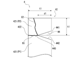
- the depth of the groove 44 up to the bottom 443 in the radial direction is d1 (see FIG. 6).
- the depth d of the groove portion 44 is 1/3 or more and 3/4 or less of the thickness t of the thick portion 421. More preferably. By doing so, it becomes easier to preferentially deform the second portion P2 over the first portion P1.
- the cross-sectional shape of the groove 44 is not limited to the V-shape described above.
- Various shapes such as a U-shape, an arc shape, a rectangular shape, and a trapezoidal shape can be selected as the cross-sectional shape of the groove portion 44.
- an annular gap G1 is formed between the non-contact region A2 and the surrounding wall 42.
- the size of the gap G1 is smaller than that of the transfer charge 8 so that the transfer charge 8 does not enter the gap G1. Since the gap G1 is formed between the non-contact area A2 and the surrounding wall 42, the gap G1 can buffer the impact applied from the cup body 21 to the surrounding wall 42 during the operation of the igniter 2. Further, by adopting a structure in which a gap G1 (a gap formed by a mold arranged at the time of injection molding of the resin material) is formed, the injection pressure of the resin material at the time of molding the holding portion 4 is the peripheral wall 211 of the cup body 21. Therefore, it is possible to prevent the deformation of the cup body 21.
- FIG. 6 and 7 are diagrams showing the mode of the crack when the second portion P2 is cracked in the igniter assembly 10 according to the first embodiment.
- Reference numerals C1 and C2 shown in the figure represent cracks.
- a crack C1 extending in the axial direction from the tip of the surrounding wall 42 develops on the proximal end side of the thin wall portion 422.
- the crack C2 extending in the axial direction from the tip of the surrounding wall 42 does not develop toward the proximal end side of the thin wall portion 422, but develops in the thin wall portion 422 in the radial direction.
- the second portion P2 is deformed and the holding portion 4 is cracked, it is more preferable that the crack is formed in the mode shown in FIG. 7 so that the crack does not develop in the first portion P1.
- reference numeral h1 shown in FIGS. 6 and 7 is the axial distance from the tip end surface of the surrounding wall 42 to the bottom portion 443, and the depth d is the radial direction up to the bottom portion 443 of the groove portion 44, as described above. Is the depth at. The position and depth of the groove portion 44 are defined by h1 and d1.
- FIG. 8 is a top view of the igniter assembly 10A according to the modified example of the first embodiment. While the surrounding wall 42 of the holding portion 4 in the igniter assembly 10 shown in FIG. 2 is formed in a continuous annular shape, the igniter assembly 10A according to the modified example 1 surrounds the holding portion 4A. It differs from the igniter assembly 10 in that the wall 42A is formed in an intermittent ring shape.
- the igniter assembly 10A is otherwise identical to the igniter assembly 10. Hereinafter, the igniter assembly 10A will be described focusing on the differences from the igniter assembly 10.
- the surrounding wall 42A is formed by arranging a plurality of interrupted walls 420 in a ring shape with a predetermined interval.
- the predetermined interval is smaller than the size of the transfer charge 8 so that the transfer charge 8 does not enter the gap G2 formed between the interrupted walls 420 adjacent to each other in the circumferential direction. This suppresses the transfer charge 8 from being arranged around the non-contact area A2.
- each interrupted wall 420 in the cross section orthogonal to the axial direction is continuous. It is smaller than the cross-sectional area of the surrounding wall 42 formed in the above.
- each interrupted wall 420 is more easily deformed than the surrounding wall 42 shown in FIG.
- the second portion P2 can be easily deformed so as to be separated from the igniter 2 preferentially over the first portion P1.
- FIG. 9 is a figure which shows the structure of the igniter assembly 10B which concerns on the modification 2 of 1st Embodiment. As shown in FIG. 9, the igniter assembly 10B is significantly different from the igniter assembly 10 shown in FIG.
- a tubular charge holder 223 is provided on the upper surface of the metal header 221 in the ignition chamber 50, and the igniter is held by the charge holder 223.
- FIG. 10 is a diagram showing a structure of an igniter assembly 10C according to a second embodiment of the present disclosure.
- the igniter assembly 10C according to the second embodiment is different from the igniter assembly 10 according to the first embodiment in that the first portion P1 and the second portion P2 are formed of resin materials having different curing times. different.
- the fragile portion is formed as an interface S1 between the first portion P1 and the second portion P2.
- the igniter assembly 10C according to the second embodiment will be described focusing on the differences from the igniter assembly 10.
- the holding portion 4C according to the second embodiment like the holding portion 4 according to the first embodiment, includes a base portion 41 that fixes the igniter 2 to the collar 3 by covering the periphery of the contact area A1, and a base portion.
- An annular surrounding wall 42 that is formed continuously with the portion 41 and surrounds the non-contact area A2 with a gap from the non-contact area A2.
- the holding portion 4C according to the second embodiment is divided into a first portion P1 including a part of the base portion 41 and a second portion P2 including a tip of the surrounding wall 42, and the first portion P1 is the first portion P1.
- the second portion P2 is formed of the first resin material, and the second portion P2 is formed of the second resin material whose curing time is later than that of the first material.
- a broken line S1 shown in FIG. 10 is different from the first portion P1 formed by the different curing times of the first resin material forming the first portion P1 and the second resin material forming the second portion P2.
- An interface with the second portion P2 is shown.
- the second portion P2 is formed in an annular shape including the entire surrounding wall 42 and a part of the base portion 41.
- the holding portion 4C according to the present embodiment is formed by integrally molding the first portion P1 and the second portion P2.
- FIG. 11 is a figure which shows the process of the shaping
- the holding portion 4C is molded by injection molding using a mold.
- the first part molding step of S101 the first part P1 is molded by melting and hardening the first resin material.
- the first resin material a thermoplastic resin generally used in injection molding, for example, polybutylene terephthalate resin, polyethylene terephthalate resin, polyamide resin, polypropylene sulfide resin, polypropylene oxide resin or the like can be used.
- the igniter 2 is placed in the mold for molding the first part, and the molten first resin material is poured into the mold and cured. As a result, the first portion P1 is formed in a state of being integrated with the igniter 2.
- the second resin material is melted and cured to form the second part P2.
- a thermoplastic resin generally used for injection molding is used as in the first resin material.
- an intermediate molded product in which the igniter 2 and the first part P1 are integrated is placed in a mold for molding the second part, and the molten second resin material is poured into the mold and cured. To do.
- the first portion P1 and the second portion P2 are joined to each other, and the holding portion 4C is molded in a state of being integrated with the igniter 2.
- the second resin material is cured after the first resin material is cured, that is, the first resin material and the second resin material have different curing timings.
- An interface S1 is formed between the first portion P1 and the second portion P2.
- the igniter 2 when the igniter 2 operates and the cup body 21 bursts, the flame that is a combustion product is released upward, and the transfer charge 8 in the transfer chamber 20 is ignited.
- the surrounding wall 42 functions as a spacer, so that the non-contact area A2 of the peripheral wall 211 is reduced. It is suppressed that the explosive agent 8 is arranged around the. This suppresses the occurrence of combustion residue or combustion delay of the transfer charge 8 after the operation of the igniter 2. As a result, it is possible to improve the output performance of the gas generator 100.
- FIG. 12 is a diagram for explaining a state when the igniter 2 operates and the cup body 21 bursts in the igniter assembly 10C according to the second embodiment.
- the cup body 21 that bursts and tries to open radially outward contacts the surrounding wall 42, and a load is applied to the surrounding wall 42.
- the interface S1 between the first portion P1 and the second portion P2 is included so that the contact portion between the ruptured cup body 21 and the surrounding wall 42 is included in the second portion. Are formed. Therefore, when a load is applied to the surrounding wall 42, a moment due to the load acts near the interface S1.
- the stress generated in the holding portion 4C due to the load locally increases near the interface S1 (stress concentration occurs).
- stress concentration occurs.
- the holding portion 4C is likely to break preferentially at the interface S1 over other portions.
- the second portion P2 is deformed so as to fall outward in the radial direction while being separated at the interface S1.
- the holding portion 4C breaks so that the second portion P2 is separated from the first portion P1.
- the second portion P2 when the surrounding wall 42 is loaded, the second portion P2 preferentially has a larger diameter than the first portion P1.
- the interface S1 is formed so as to deform outward in the direction.
- the energy due to the load applied to the surrounding wall 42 is easily consumed for the deformation, so that the first portion P1 is suppressed from being significantly deformed.
- the “fragile portion” is formed as the interface S1 between the first portion P1 and the second portion P2.
- the first resin material has a higher melting point than the second resin material. By doing so, it is possible to suppress melting of the cured first resin material when the molten second resin material is poured into the mold in the above-described second portion molding step. As a result, the interface S1 between the first resin material and the second resin material can be formed, and the deformation of the first portion P1 due to the melting of the first resin material can be suppressed.
- the interface S1 between the first part P1 and the second part P2 is not limited to that shown in FIG.
- the entire base portion 41 may be the first portion P1 and the entire surrounding wall 42 may be the second portion P2.
- the portion of the holding portion 4C from the tip to the middle of the surrounding wall 42 may be designated as the second portion P2, and the remaining portion may be designated as the first portion P1.
- the first resin material and the second resin material may be the same type of resin material or different types of resin material.
- the igniter assembly disclosed in the present application is applied to the gas generator of the type in which the gas generating agent 7 is burned through the transfer charge 8 serving as the combustion agent has been described as an example.
- the disclosed igniter assembly may be applied to a gas generator in which the igniter burns a gas generator without the intervention of an explosive.
- the gas generating agent corresponds to the combustion agent in the disclosure of the present application.
- the size is smaller than the size of the combustion agent (transfer charge 8) between the inner cylinder 5 and the surrounding walls 42, 42B. A gap may be formed.
Landscapes
- Physics & Mathematics (AREA)
- Fluid Mechanics (AREA)
- Engineering & Computer Science (AREA)
- Mechanical Engineering (AREA)
- Air Bags (AREA)
Abstract
点火器組立体は、点火器とカラーと保持部とを備え、点火器は、筒状の周壁と周壁の一端を閉塞する蓋壁とを有するカップ体とカップ体と共に燃焼剤の収容空間を画定する閉塞部とを有し、周壁は、該周壁の軸方向において、閉塞部に接触した接触領域と閉塞部に接触しない非接触領域とに区分され、保持部は、接触領域の周囲を覆うベース部と、ベース部に連続して形成され、非接触領域を包囲する包囲壁と、を備え、保持部における、ベース部の少なくとも一部を含む第1部位と、第1部位よりも放出方向側の部位であって包囲壁の先端を含む第2部位と、の間には、点火器が作動することで包囲壁に荷重が掛かったときに、第2部位が第1部位と比べて優先的に径方向外向きに変形するように、脆弱部が形成されている。
Description
本発明は、ガス発生器における点火器組立体、及び点火器組立体における保持部の成形方法に関する。
従来、エアバッグ用ガス発生器等の起動装置として、点火器が広く用いられている。点火器をガス発生器に取り付ける場合、ハウジング側に取り付けられたカラーに樹脂材料からなる保持部を介して点火器を固定する方法が知られている。これに関連して、点火器の周囲に環状部材を配置することで、点火器の周囲にガス発生剤が配置されることを抑制し、ガス発生剤の燃焼残りや燃焼遅れを発生し難くしたガス発生器が開示されている(例えば、特許文献1)。
ここで、ガス発生器の動作時においては、点火器が作動することにより、燃焼剤を着火するための点火薬を収容した金属カップが破裂することで火炎が放出される。樹脂材料からなる保持部を介して点火器をカラーに固定する構造を採用した場合、点火器の作動時に保持部に作用する荷重によって保持部が変形し、保持部において点火器とカラーとを固定する部位に亀裂や破損が生じる場合がある。そのような場合、亀裂や破損の状態によっては、点火器の保持が不十分となって点火器が保持部から浮き上がったり、ガス発生器としてのシール性が損なわれたりする虞がある。
本願開示の技術は、上記した問題に鑑みてなされたものであり、点火器の作動時に、点火器をカラーに固定するための保持部に亀裂や破損が生じることによる不具合を抑制可能な点火器組立体を提供することを目的とする。
上記課題を解決するために、本願開示の技術は、以下の構成を採用した。即ち、本願開示の点火器組立体は、燃焼剤を着火するための点火薬を収容する収容空間を含む点火器と、前記点火器を支持するカラーと、前記カラーに対して前記点火器を固定する、樹脂材料で形成された保持部と、を備え、前記点火器は、筒状の周壁と、前記周壁の一端を閉塞する蓋壁と、を有し、前記蓋壁が該点火器の作動時における前記点火薬の燃焼生成物の放出方向側に位置するように配置されたカップ体と、前記カップ体の他端に形成された開口を閉塞するように配置され、前記カップ体と共に前記収容空間を画定する閉塞部と、を有し、前記周壁は、該周壁の軸方向において、前記閉塞部に接触した接触領域と、前記接触領域よりも前記蓋壁側の領域であって前記閉塞部に接触しない非接触領域と、に区分され、前記保持部は、前記接触領域の周囲を覆うことで前記カラーに対して前記点火器を固定するベース部と、前記ベース部に連続して形成され、前記非接触領域を包囲することで、前記非接触領域の周囲に前記燃焼剤が配置されることを抑制するように構成された環状の包囲壁と、を備え、前記保持部における、前記ベース部の少なくとも一部を含む第1部位と、前記第1部位よりも前記放出方向側の部位であって前記包囲壁の先端を含む第2部位と、の間には、前記点火器が作動することで前記包囲壁に荷重が掛かったときに、前記第2部位が前記第1部位と比べて優先的に径方向外向きに変形するように、脆弱部が形成されている。
本願開示の点火器組立体によると、保持部に形成された包囲壁により、非接触領域の周囲に燃焼剤が配置されることが抑制される。つまり、仮に、包囲壁が存在しないと、カラーの上端面から蓋壁側に突出したカップ体の周囲に空間が形成されることになる。ここで、仮に、点火器の作動時に非接触領域の周囲に燃焼剤が配置されていると、該燃焼剤は、点火器に対して燃焼生成物の放出方向から外れた場所に位置することとなる。その結果、該燃焼剤が十分に燃焼せず、燃焼剤の燃焼残りや燃焼遅れが発生する虞がある。一方、本願開示の点火器組立体によると、非接触領域の周囲に燃焼剤が配置されることが抑制されるため、点火器の作動後における燃焼剤の燃焼残りや燃焼遅れの発生を抑制することができる。その結果、ガス発生器の出力性能を向上させることができる。また、包囲壁が燃焼剤に対してクッションの役割を果たすことでガス発生器組立後の燃焼剤のがたつきを防止することや、ガス発生器を容易に組み立てることができる。
更に、本願開示の点火器組立体の保持部には、点火器が作動することで包囲壁に荷重が掛かったときに、第2部位が第1部位と比べて優先的に径方向外向きに変形するように、脆弱部が形成されている。これにより、包囲壁に掛かった荷重によるエネルギーが第2部位の変形に費やされ易くなるため、第1部位が大きく変形することが抑制される。その結果、点火器の作動時に第1部位に亀裂や破損が生じることが抑制される。ここで、第1部位は、カラーに対して点火器を固定するためのベース部の少なくとも一部を含む部位であるから、第1部位における亀裂や破損の発生を抑制することで、点火器の浮きやシール性の低下といった不具合の発生を抑制することができる。
なお、本願開示の燃焼剤には、エアバッグを膨張させるための燃焼ガスを発生するガス発生剤や、ガス発生剤を燃焼させるための伝火薬が含まれる。また、第2部位の変形は、破壊や破断を伴うものであってもよく、第2部位が延性破壊や脆性破壊によって第1部位から分離してもよい。
また、点火器組立体は、上述の脆弱部が以下のように形成されてもよい。即ち、点火器組立体において、前記包囲壁は、厚肉部と、周方向に沿って延在すると共に径方向の厚みが前記厚肉部よりも薄い薄肉部と、を有し、前記脆弱部は、前記薄肉部として形成されてもよい。これにより、点火器作動時に包囲壁に加えられる荷重によって保持部に生じる応力を、薄肉部に集中させることができ、第1部位よりも第2部位を優先的に変形させることができる。
また、点火器組立体において、脆弱部を薄肉部として形成する場合、前記包囲壁の周方向に沿って延在すると共に径方向に凹んだ溝部が前記包囲壁に形成されることで、前記薄肉部が形成されてもよい。これによれば、包囲壁に溝が形成されているため、包囲壁に荷重が加えられたときに、包囲壁が径方向外側に倒れるように変形し易くなる。その結果、第1部位よりも第2部位を優先的に変形させ易くすることができる。なお、該溝は、包囲壁の内周面と外周面のうち、何れに形成されてもよい。
また、点火器組立体において、薄肉部を上述の溝部によって形成する場合、前記厚肉部の外周面から前記溝部の底部までの前記径方向における深さは、前記厚肉部の前記径方向における厚みの1/3以上3/4以下であることが好ましい。そうすることで、第1部位よりも第2部位を優先的に変形させることが容易となる。
また、点火器組立体は、上述の脆弱部が以下のように形成されてもよい。即ち、点火器組立体において、前記第1部位が第1の樹脂材料により形成され、前記第2部位が前記第1の樹脂材料よりも硬化時期の遅い第2の樹脂材料により形成され、前記脆弱部は、前記第1部位と前記第2部位との間の界面として形成されてもよい。これによると、第1部位を形成する第1の樹脂材料と第2部位を形成する第2の樹脂材料の硬化時期を異ならせることで、第1部位と第2部位との間に界面を形成している。なお、硬化時期は成形時期とみなすことができる。これによって、第1部位を第1の樹脂材料によって先に射出成形し、硬化後にその上から第2の樹脂材料によって射出成形するものである。これにより、点火器作動時に包囲壁に加えられる荷重によって保持部に生じる応力を、上記界面に集中させることができる。その結果、前記第2部位が前記第1部位と比べて優先的に径方向外向きに変形させ易くすることができる。
また、点火器組立体において、脆弱部を第1部位と第2部位との界面として形成する場合、以下の成形方法によって保持部を成形してもよい。即ち、本願開示の保持部の成形方法は、前記第1の樹脂材料を溶融し、硬化することで、前記第1部位を成形することと、前記第1の樹脂材料が硬化した後で、前記第2の樹脂材料を溶融し、硬化することで、前記第2部位を成形することと、を含んでもよい。
また、点火器組立体において、脆弱部を第1部位と第2部位との界面に形成する場合、前記第1の樹脂材料の方が前記第2の樹脂材料よりも融点が高いものであってもよい。これにより、第2部位を成形することにおいて、溶融状態の第2の樹脂材料を流し込んだ際に、硬化している第1の樹脂材料が溶融することを抑制できる。その結果、第1の樹脂材料と第2の樹脂材料との界面を形成することができ、また、第1の樹脂材料が溶融することによる第1部位の変形を抑制することができる。
なお、上述した第1の樹脂材料と第2の樹脂材料は、同じ種類の樹脂材料であってもよいし、種類の異なる樹脂材料であってもよい。
また、点火器組立体において、前記包囲壁は、前記周壁の前記非接触領域との間に環状の隙間を形成し、前記隙間の大きさは、前記燃焼剤の大きさよりも小さくてもよい。これによると、点火器の作動時にカップ体から包囲壁へ加わる衝撃を該間隙によって緩衝することができる。また、該間隙の大きさを燃焼剤の大きさよりも小さくすることで、該間隙に燃焼剤が入り込むことを抑制できる。
また、点火器組立体において、前記包囲壁は、周方向において所定の間隔を空けて環状に配列された複数の断続壁によって形成され、前記所定の間隔は、前記燃焼剤の大きさよりも小さく形成されてもよい。これによれば、包囲壁が複数の断続壁によって形成されているため、各断続壁の軸方向に直交する断面における断面積を小さくすることができる。これにより、各断続壁を変形し易くすることができる。その結果、包囲壁に荷重が加えられたときに、第2部位を第1部位よりも優先的に点火器から離れるように変形させ易くすることができる。また、該所定の間隔を燃焼剤の大きさよりも小さくすることで、隣接する断続壁同士の間に形成される隙間に燃焼剤が入り込むことを抑制できる。また、包囲壁を複数の断続壁によって形成する場合、所定の間隔を一の断続壁の周方向における長さよりも短くすることで、第2部位を更に変形させ易くすることができる。
本願開示の技術によれば、点火器の作動時に、点火器をカラーに固定するための保持部に亀裂や破損が生じることによる不具合を抑制することができる。
以下、図面を参照して本願開示の実施形態に係るガス発生器における点火器組立体について説明する。なお、各実施形態における各構成及びそれらの組み合わせ等は一例であって、本発明の主旨から逸脱しない範囲内で、適宜、構成の付加、省略、置換、及びその他の変更が可能である。本発明は、実施形態によって限定されることはなく、請求の範囲によってのみ限定される。
<第1実施形態>
図1は、本願開示の第1実施形態に係る点火器組立体10を用いたエアバッグ用ガス発生器(以下、ガス発生器)100の軸方向断面図である。図1に示すように、ガス発生器100は、ハウジング1、点火器2、カラー3、保持部4、内筒5、クーラント・フィルタ6を備える。点火器2、カラー3、保持部4、内筒5、クーラント・フィルタ6は、ハウジング1の内部空間に配置されている。本明細書では、点火器2、カラー3、保持部4を含んだ構成を点火器組立体10と称する。ガス発生器100は、点火器2を作動させることによりハウジング1内に充填されたガス発生剤7を燃焼させ、その燃焼性生物である燃焼ガスをハウジング1の外部に放出することで、エアバッグ(図示せず)を膨張させるように構成されている。以下、ガス発生器100の各構成について説明する。
図1は、本願開示の第1実施形態に係る点火器組立体10を用いたエアバッグ用ガス発生器(以下、ガス発生器)100の軸方向断面図である。図1に示すように、ガス発生器100は、ハウジング1、点火器2、カラー3、保持部4、内筒5、クーラント・フィルタ6を備える。点火器2、カラー3、保持部4、内筒5、クーラント・フィルタ6は、ハウジング1の内部空間に配置されている。本明細書では、点火器2、カラー3、保持部4を含んだ構成を点火器組立体10と称する。ガス発生器100は、点火器2を作動させることによりハウジング1内に充填されたガス発生剤7を燃焼させ、その燃焼性生物である燃焼ガスをハウジング1の外部に放出することで、エアバッグ(図示せず)を膨張させるように構成されている。以下、ガス発生器100の各構成について説明する。
[ハウジング]
ハウジング1は、それぞれが有底略円筒状に形成された金属製の上部シェル11及び下部シェル12が互いの開口端同士を向き合わせた状態で接合されることによって、軸方向の両端が閉塞した短尺円筒状に形成されている。ここで、ハウジング1の軸方向に沿う方向をガス発生器100の上下方向と定義し、上部シェル11側(即ち、図1における上側)をガス発生器100の上側とし、下部シェル12側(即ち、図1における下側)をガス発生器100の下側とする。
ハウジング1は、それぞれが有底略円筒状に形成された金属製の上部シェル11及び下部シェル12が互いの開口端同士を向き合わせた状態で接合されることによって、軸方向の両端が閉塞した短尺円筒状に形成されている。ここで、ハウジング1の軸方向に沿う方向をガス発生器100の上下方向と定義し、上部シェル11側(即ち、図1における上側)をガス発生器100の上側とし、下部シェル12側(即ち、図1における下側)をガス発生器100の下側とする。
上部シェル11は、略円盤状の天板部111と、天板部111の周縁から下方に延在する外周壁部112と、外周壁部112の先端部から径方向外側に延在するフランジ部113と、を有する。また、下部シェル12は、略円盤状の底板部121と、底板部121の周縁から上方に延在する外周壁部122と、外周壁部122の先端部から半径方向外側に延在するフランジ部123と、を有する。このような上部シェル11及び下部シェル12は、ステンレス鋼板をプレスすることで成形される。上部シェル11と下部シェル12は、フランジ部113とフランジ部123とが重ね合わされてレーザ溶接等によって接合されることで、ハウジング1を形成している。
上部シェル11の外周壁部112には、ガス噴出口13が周方向に並んで複数形成されている。ガス噴出口13は、シールテープ14により閉塞されている。このシールテープ14としては、片面に粘着部材が塗布されたアルミニウム箔等が利用される。これにより、ハウジング1の気密性が確保されている。
また、図1に示すように、下部シェル12の底板部121の中央には、下方に向かって突出する開口筒部1211が設けられている。開口筒部1211の内壁は、ハウジング1の内部空間と外部空間とを連通する開口15を形成している。
[内筒]
内筒5は、両端が開口した筒形状を有しており、中心軸が上下方向(即ち、ハウジング1の軸方向)と一致する姿勢で配設されている。内筒5は、ステンレス鋼管により形成される。図1に示すように、内筒5の下端が開口15に嵌入されており、該下端において内筒5の外周面が開口15の内周面に当接している。また、内筒5の上端が上部シェル11の天板部111に当接している。これにより、ハウジング1の内部空間は、内筒5によって径方向に区分されている。ハウジング1の内部空間のうち、内筒5の内側は、点火器組立体10が配設されると共に燃焼剤としての伝火薬8が充填される円柱状の伝火室20を規定し、内筒5の外側は、ガス発生剤7が充填される環状の燃焼室30を規定する。また、内筒5には、伝火室20と燃焼室30とを連通する孔である伝火孔51が周方向に複数並んで形成されている。伝火孔51は、シールテープ52により塞がれている。これにより、伝火室20の気密性が確保されている。内筒5とハウジング1は、例えば、互いの接触部分において溶接されることで接合される。
内筒5は、両端が開口した筒形状を有しており、中心軸が上下方向(即ち、ハウジング1の軸方向)と一致する姿勢で配設されている。内筒5は、ステンレス鋼管により形成される。図1に示すように、内筒5の下端が開口15に嵌入されており、該下端において内筒5の外周面が開口15の内周面に当接している。また、内筒5の上端が上部シェル11の天板部111に当接している。これにより、ハウジング1の内部空間は、内筒5によって径方向に区分されている。ハウジング1の内部空間のうち、内筒5の内側は、点火器組立体10が配設されると共に燃焼剤としての伝火薬8が充填される円柱状の伝火室20を規定し、内筒5の外側は、ガス発生剤7が充填される環状の燃焼室30を規定する。また、内筒5には、伝火室20と燃焼室30とを連通する孔である伝火孔51が周方向に複数並んで形成されている。伝火孔51は、シールテープ52により塞がれている。これにより、伝火室20の気密性が確保されている。内筒5とハウジング1は、例えば、互いの接触部分において溶接されることで接合される。
[クーラント・フィルタ]
クーラント・フィルタ6は、燃焼室30においてガス発生剤7を取り囲んで環状に配設され、ハウジング1の外周壁部112及び外周壁部122との間に、環状の間隙40を画定している。クーラント・フィルタ6は、ステンレス鋼製平編の金網を半径方向に重ね、半径方向及び軸方向に圧縮することで形成されている。
クーラント・フィルタ6は、燃焼室30においてガス発生剤7を取り囲んで環状に配設され、ハウジング1の外周壁部112及び外周壁部122との間に、環状の間隙40を画定している。クーラント・フィルタ6は、ステンレス鋼製平編の金網を半径方向に重ね、半径方向及び軸方向に圧縮することで形成されている。
このように構成されたガス発生器100において、センサ(図示せず)が衝撃を感知すると、所定信号が点火器2に送られて点火器2が作動し、伝火室20内の伝火薬8を点火する。伝火薬8の燃焼により、伝火室20内に高温の火炎が生成される。この火炎は、シールテープ52を破って伝火孔51より燃焼室30に噴出し、ガス発生剤7を点火する。そして、ガス発生剤7の燃焼により高温・高圧のガスが生成され、この燃焼ガスは、クーラント・フィルタ6の全領域を通過する。このとき、クーラント・フィルタ6は、燃焼室30で発生した燃焼ガスを冷却し、燃焼残渣を捕集する。クーラント・フィルタ6によって冷却・浄化された燃焼ガスは、間隙40を通り、シールテープ14を破ってガス噴出口13より噴出し、エアバッグ(図示せず)内に流入する。これにより、エアバッグが膨張することで、乗員と堅い構造物の間にクッションが形成され、衝撃から乗員が保護される。ガス発生剤7としては、例えば、硝酸グアニジン(41重量%)、塩基性硝酸銅(49重量%)及びバインダーや添加物からなる、単孔円柱状のものを用いることができる。また、伝火薬8としては、例えば、ニトログアニジン(34重量%)、硝酸ストロンチウム(56重量%)からなるものを用いることができる。
[点火器組立体]
次に、点火器組立体10について説明する。図2は、第1実施形態に係る点火器組立体10の構造を示す図である。点火器組立体10は、伝火薬8を着火するための点火薬(図示なし)を収容する収容空間としての点火室50を含む点火器2と、点火器2を支持するカラー3と、カラー3に対して点火器2を固定する、樹脂材料で形成された保持部4と、を備える。
次に、点火器組立体10について説明する。図2は、第1実施形態に係る点火器組立体10の構造を示す図である。点火器組立体10は、伝火薬8を着火するための点火薬(図示なし)を収容する収容空間としての点火室50を含む点火器2と、点火器2を支持するカラー3と、カラー3に対して点火器2を固定する、樹脂材料で形成された保持部4と、を備える。
[点火器]
点火器2は、伝火室20の外部から供給される着火電流により、点火室50内の点火薬を燃焼させる。点火器2は、保持部4によって伝火室20の下部に固定されている。点火器2が作動することで点火薬が燃焼し、その燃焼生成物が上方に放出され、伝火薬8が点火される。以下、点火器2から燃焼生成物が放出される方向(本例では上方)を、放出方向と呼ぶこともある。
点火器2は、伝火室20の外部から供給される着火電流により、点火室50内の点火薬を燃焼させる。点火器2は、保持部4によって伝火室20の下部に固定されている。点火器2が作動することで点火薬が燃焼し、その燃焼生成物が上方に放出され、伝火薬8が点火される。以下、点火器2から燃焼生成物が放出される方向(本例では上方)を、放出方向と呼ぶこともある。
図2に示すように、点火器2は、一端が閉塞し他端が開口したカップ体21と、カップ体21の他端に形成された開口を閉塞するように配置され、カップ体21と共に点火室50を画定する閉塞部22と、を有する。
カップ体21は、筒状の周壁211と、周壁211の一端を閉塞する蓋壁212と、によってカップ状に形成されている。周壁211は、その中心軸が上下方向と一致するようにして配設されている。蓋壁212は、周壁211に連続して形成されており、周壁211の上端部を閉塞することで、点火室50の上壁を構成している。カップ体21は、即ち、点火器2の作動時における点火薬の燃焼生成物の放出方向側に蓋壁212が位置するように配置されている。このカップ体21は、金属製の内側カップ及び樹脂製の外側カップが重ね合わされた二重構造を有している。但し、カップ体21の材質はこれに限定しない。
閉塞部22は、周壁211の下端に配置された金属ヘッダ221と、金属ヘッダ221から下方に延在する一対の通電ピン222,222と、を有する。金属ヘッダ221は、金属材料により略円柱状に形成されており、その外周面において周壁211と接触している。金属ヘッダ221の中央部には、上下に貫通する貫通孔が形成されている。一対の通電ピン222,222の一方は、金属ヘッダ221の貫通孔に挿通された状態で、絶縁体を介して金属ヘッダ221と接合されている。また、点火室50の底部には、該通電ピン222と金属ヘッダ221を電気的に接続する抵抗体であるブリッジワイヤ23が配線されている。一対の通電ピン222,222の他方は、金属ヘッダ221の下面に接合されている。閉塞部22は、周壁211の下端を閉塞することで、点火室50の下壁を構成している。
ここで、図2に示すように、閉塞部22がカップ体21の開口を閉塞するようにカップ体21の内部に配置されることで、カップ体21の周壁211は、軸方向において、閉塞部22に接触した接触領域A1と、接触領域A1よりも放出方向側の領域であって閉塞部22に接触しない非接触領域A2と、に区分されている。
点火器2は、一対の通電ピン222,222に外部電源を接続可能となるように、伝火室20内に配設されている。点火器2が作動する際は、外部電源によって二本の通電ピン222,222間に電圧印加され、ブリッジワイヤ23に電流が流れ、ブリッジワイヤ23に生じるジュール熱により点火室50内の点火薬が燃焼する。これに伴って点火室50内の圧力が上昇することでカップ体21が破裂し、点火薬の燃焼生成物である高温の火炎が放出方向である上方に放出される。これにより、伝火室20内の伝火薬8が点火される。
[カラー]
カラー3は、金属材料により形成され、点火器2における点火室50よりも下方の領域を取り囲む筒形状を有している。但し、カラー3の材質は金属材料に限定されない。カラー3の外周面は、内筒5の内周面に当接している。図2に示すように、内筒5にカラー3を嵌入した状態で内筒5の下端をかしめることで、カラー3が伝火室20の下部に固定されている。なお、カラー3は、内筒5や下部シェル12と一体に成形されていてもよい。
カラー3は、金属材料により形成され、点火器2における点火室50よりも下方の領域を取り囲む筒形状を有している。但し、カラー3の材質は金属材料に限定されない。カラー3の外周面は、内筒5の内周面に当接している。図2に示すように、内筒5にカラー3を嵌入した状態で内筒5の下端をかしめることで、カラー3が伝火室20の下部に固定されている。なお、カラー3は、内筒5や下部シェル12と一体に成形されていてもよい。
[保持部]
図2に示すように、点火器2とカラー3との間に樹脂製の保持部4が介装されることで、カラー3に対して点火器2が固定されている。保持部4は、接触領域A1の周囲を覆うことでカラー3に対して点火器2を固定するベース部41と、ベース部41に連続して形成され、非接触領域A2を包囲することで、非接触領域A2の周囲に伝火薬8が配置されることを抑制するように構成された環状の包囲壁42と、を有する。
図2に示すように、点火器2とカラー3との間に樹脂製の保持部4が介装されることで、カラー3に対して点火器2が固定されている。保持部4は、接触領域A1の周囲を覆うことでカラー3に対して点火器2を固定するベース部41と、ベース部41に連続して形成され、非接触領域A2を包囲することで、非接触領域A2の周囲に伝火薬8が配置されることを抑制するように構成された環状の包囲壁42と、を有する。
ベース部41は、周壁211における接触領域A1の外周面、金属ヘッダ221の下面、カラー3の上面、カラー3の内周面を覆うことで、カラー3と保持部4とを互いに固定し、且つ、伝火室20の気密性を維持している。ベース部41の下端には、通電ピン222,222に外部電源からの電力を供給するコネクタ(図示せず)を挿入可能なコネクタ挿入空間43が形成されている。ベース部41は、一対の通電ピン222,222の下端がコネクタ挿入空間43内に露出するように、一対の通電ピン222,222の一部を覆い、保持している。ベース部41によって、一対の通電ピン222,222同士の絶縁性が保たれている。
包囲壁42は、ベース部41に連続すると共にベース部41から上方に延在した環状の部位として形成されている。包囲壁42の基端から先端(上端)までの長さは、非接触領域A2の軸方向における長さと略同等である。但し、本願開示の技術はこれに限定されない。包囲壁42は、スペーサとしての機能を有しており、包囲壁42によって非接触領域A2が径方向外側から取り囲まれることで、点火器組立体10をガス発生器の所定部位に配置したときに非接触領域A2の径方向における周囲、より詳細には、非接触領域A2と内筒5の内周面との間に伝火薬8が配置されることが抑制されている。つまり、包囲壁42の外周面は、少なくともその一部がガス発生器100の内筒5の内周面と接触するか、あるいは内筒5との間に伝火薬8が入り込まない程度の隙間を形成している。なお、包囲壁42が伝火薬8に対してクッションの役割を果たすことで、ガス発生器100の組立後における伝火薬8のがたつきが防止されている。また、仮に、包囲壁42が形成されていないと、点火器組立体は、カラー3の上端面からカップ体21が突出するような構成となる。そうすると、ガス発生器100の組立において、伝火薬8が充填された内筒5の内部に直接カップ体21を押し込む必要があり、その結果、伝火薬8が割れたり、組立自体が困難となる虞がある。これに対して、点火器組立体10は、包囲壁42によってカップ体21を取り囲む構成とすることで、ガス発生器100の組立において伝火薬8の割れを抑制しつつも容易に組み立てることができる。
図2に示すように、包囲壁42の外周面における軸方向の中途には、径方向内側に凹んだ溝部44が周方向に沿って延在している。溝部44は、径方向外側に向かって上方に傾斜した上壁441と径方向外側に向かって下方に傾斜した下壁442とが接続されることで、径方向外側に開口したV字状の断面形状を有している。上壁441と下壁442との接続部位は、溝部44の底部443を形成している。底部443は、溝部44において最も径方向内側に位置する部位、即ち、最も凹んだ部位である。溝部44が形成されることにより、包囲壁42には、包囲壁42の先端側及び基端側に形成された一対の厚肉部421,421と、一対の厚肉部421,421に挟まれ、径方向の厚みが一対の厚肉部421,421よりも薄い薄肉部422と、が形成されている。薄肉部422は、溝部44の底部443と包囲壁42の内周面との間に形成されており、周方向に沿って延在している。
ここで、薄肉部422は、保持部4において、ベース部41の少なくとも一部を含む第1部位P1と、第1部位P1よりも放出方向側の部位であって包囲壁42の先端を含む第2部位P2と、の間に形成されている。図2~図5に示す破線B1は、説明の便宜上、保持部4を第1部位P1と第2部位P2とに区分するものであり、第1部位P1と第2部位P2との間に界面が存在することを表すものではない。本実施形態では、ベース部41と包囲壁42の基端側の厚肉部421とを含む部位が第1部位P1を構成し、包囲壁42の先端側の厚肉部421が第2部位P2を構成する。本実施形態では、「脆弱部」が薄肉部422として、第1部位P1と第2部位P2との間に形成されている。
このような保持部4は、点火器2の製造工程において、樹脂材料を射出成形することで形成される。保持部4を形成する樹脂材料としては、硬化後において耐熱性や耐久性、耐腐食性等に優れた樹脂材料を好適に利用することができる。このような樹脂材料としては、例えば、ポリブチレンテレフタレート樹脂、ポリエチレンテレフタレート樹脂、ポリアミド樹脂、ポリプロピレンスルフィド樹脂、ポリプロピレンオキシド樹脂等の熱可塑性樹脂や、エポキシ樹脂等の熱硬化性樹脂が例示される。
以下、点火器2が作動したときの保持部4の挙動について説明する。図3~図5は、第1実施形態に係る点火器組立体10において、点火器2が作動してカップ体21が破裂したときの様子を説明するための図である。
上述のように、点火器2の作動時においては、点火室50内の点火薬が燃焼することで点火室50内の圧力が上昇し、図3に示すように、カップ体21が破裂する。このとき、カップ体21は、蓋壁212の中央部を起点に破裂する。これにより、燃焼生成物である火炎が上方へ放出され、伝火室20内の伝火薬8が点火される。ここで、仮に、包囲壁42が存在しないと、カラー3の上端面から蓋壁側に突出したカップ体21の周囲に空間が形成されることになる。そして、火炎が上方に放出されることから、仮に、点火器2の作動時に周壁211の非接触領域A2の径方向における周囲に伝火薬8が配置されていると、該伝火薬8は、点火器2に対して火炎の放出方向から外れた場所に位置することとなる。その結果、該伝火薬8が十分に燃焼せず、伝火薬8の燃焼残りや燃焼遅れが発生する虞がある。これに対して、実施形態に係る点火器組立体10は、包囲壁42がスペーサとして機能することで、図2に示すように、周壁211の非接触領域A2の周囲に伝火薬8が配置されることが抑制されている。これにより、点火器2作動後における伝火薬8の燃焼残りや燃焼遅れの発生を抑制することができる。その結果、ガス発生器100の出力性能を向上させることができる。
図3に示すように、破裂したカップ体21は、伝火室20内の圧力により、接触領域A1を基端として非接触領域A2が径方向外側に開くように変形する。これにより、点火器2の作動後は、径方向外側に開こうとするカップ体21が包囲壁42に接触することで、包囲壁42に荷重F1が掛かる。
ここで、点火器2が作動すると、包囲壁42に掛かった加重F1により保持部4が変形し、保持部4に亀裂や破損が生じる場合がある。このとき、仮に、亀裂や破損の状態が好ましくないものであると、点火器2の保持が不十分となって点火器2が保持部4から浮き上がったり、伝火室20のシール性が損なわれたりする(燃焼ガスの漏れ)といった不具合が生じる虞がある。
これに対して、本実施形態に係る点火器組立体10は、包囲壁42に薄肉部422を脆弱部として形成し、包囲壁42に荷重が掛かったときに、第2部位P2を第1部位P1と比べて優先的に変形させることで、上述の不具合を抑制することができる。以下、具体的に説明する。
図3に示すように、保持部4において、破裂したカップ体21と包囲壁42との接触箇所が第2部位P2に含まれるように、薄肉部422が形成されている。これにより、第2部位P2にカップ体21が接触するため、薄肉部422に荷重F1によるモーメントが作用する。上述のように、薄肉部422が薄肉に形成されているため、荷重F1によって保持部4に生じる応力は、薄肉部422において局所的に増大する(応力集中が発生する)。これにより、保持部4は、薄肉部422において他の部位よりも優先的に変形し易くなっている。具体的には、図4に示すように、第2部位P2が薄肉部422を支点に径方向外向きに倒れるように変形する。やがて、図5に示すように、薄肉部422に径方向に延びる亀裂が生じ、第2部位P2が第1部位P1から分離するようにして保持部4が破断する。このように、本実施形態では、包囲壁42に薄肉部422を形成することで、点火器2の作動時、第2部位P2を第1部位P1と比べて優先的に径方向外向きに変形させることができる。
[作用・効果]
以上のように、本実施形態に係る点火器組立体10は、保持部4における、第1部位P1と第2部位P2との間に、包囲壁42に荷重が掛かったときに、第2部位P2が第1部位P1と比べて優先的に径方向外側に変形するように、脆弱部が形成されている。これにより、包囲壁42に掛かった荷重によるエネルギーが第2部位の変形に費やされ易くなるため、第1部位P1が大きく変形することが抑制される。その結果、点火器2の作動時に第1部位P1に亀裂や破損が生じることが抑制される。上述のように、第1部位P1は、カラー3に対して点火器2を固定するためのベース部41の少なくとも一部を含む部位である。そのため、第1部位P1における亀裂や破損の発生を抑制することで、点火器2の浮きや伝火室20のシール性の低下といった不具合の発生を抑制することができる。以上より、本実施形態に係る点火器組立体10によれば、点火器2の作動時に、点火器2をカラー3に固定するための保持部4に亀裂や破損が生じることによる不具合を抑制することができる。
以上のように、本実施形態に係る点火器組立体10は、保持部4における、第1部位P1と第2部位P2との間に、包囲壁42に荷重が掛かったときに、第2部位P2が第1部位P1と比べて優先的に径方向外側に変形するように、脆弱部が形成されている。これにより、包囲壁42に掛かった荷重によるエネルギーが第2部位の変形に費やされ易くなるため、第1部位P1が大きく変形することが抑制される。その結果、点火器2の作動時に第1部位P1に亀裂や破損が生じることが抑制される。上述のように、第1部位P1は、カラー3に対して点火器2を固定するためのベース部41の少なくとも一部を含む部位である。そのため、第1部位P1における亀裂や破損の発生を抑制することで、点火器2の浮きや伝火室20のシール性の低下といった不具合の発生を抑制することができる。以上より、本実施形態に係る点火器組立体10によれば、点火器2の作動時に、点火器2をカラー3に固定するための保持部4に亀裂や破損が生じることによる不具合を抑制することができる。
なお、第2部位P2は、延性破壊や脆性破壊によって、第1部位から分離してもよい。また、第2部位P2の変形は、上述のように破壊や破断を伴わないものであってもよい。
また、本実施形態では、脆弱部が薄肉部422として包囲壁42に形成された場合について説明したが、脆弱部がベース部41に形成されてもよい。脆弱部は、第1部位と第2部位との間に設けられていればよく、第1部位はベース部の少なくとも一部を含む部位であり、第2部位は第1部位よりも放出方向側の部位であって、包囲壁の先端を含む部位であればよい。
また、上述のように、本実施形態では、包囲壁42が厚肉部421と周方向に沿って延在すると共に径方向の厚みが厚肉部421よりも薄い薄肉部422と、を有しており、薄肉部422として脆弱部が形成されている。これにより、荷重F1によって保持部4に生じる応力を、薄肉部422に集中させることができ、第1部位P1よりも第2部位P2を優先的に変形させることができる。
また、上述のように、本実施形態では、包囲壁42に周方向に沿って延在すると共に径方向に凹んだ溝部44が形成されることで、薄肉部422が形成されている。これによれば、包囲壁42に溝が形成されているため、包囲壁42に荷重が掛かったときに、包囲壁42が径方向外側に倒れるように変形し易くなる。その結果、第1部位P1よりも第2部位P2を優先的に変形させ易くすることができる。なお、本実施形態では、溝部44が包囲壁42の外周面において径方向内側に凹んだ溝として形成されていたが、本願開示の技術はこれに限定されない。即ち、溝部44は、包囲壁42の内周面において径方向外側に凹んだ溝として形成されていてもよい。
ここで、厚肉部421の径方向における厚みをt1とし、溝部44の底部443までの径方向における深さをd1とする(図6参照)。本実施形態のように包囲壁42に溝部44を形成することで薄肉部422を形成する場合、溝部44の深さdは、厚肉部421の厚みtの1/3以上3/4以下であることが、より好ましい。そうすることで、第1部位P1よりも第2部位P2を優先的に変形させることが容易となる。
なお、溝部44の断面形状は上述したV字形状に限定されない。溝部44の断面形状は、U字状、円弧状、矩形状、台形状など、種々の形状を選択することができる。
ここで、図2に示すように、非接触領域A2と包囲壁42との間には、環状の間隙G1が形成されている。また、間隙G1の大きさは、間隙G1に伝火薬8が入り込まないように、伝火薬8よりも小さく形成されている。非接触領域A2と包囲壁42との間に間隙G1が形成されているため、点火器2の作動時にカップ体21から包囲壁42へ加わる衝撃を間隙G1によって緩衝することができる。また、間隙G1(樹脂材料の射出成型時に、配置される型によって形成された間隙)が形成される構造とすることで、保持部4の成形時に樹脂材料の射出圧力がカップ体21の周壁211に直接及ぶことを抑制し、カップ体21の変形を抑制することができる。
[確認試験]
図6及び図7は、第1実施形態に係る点火器組立体10において第2部位P2に亀裂が生じた場合の、亀裂の態様を示す図である。図中に示す符号C1及びC2は、亀裂を表す。図6では、包囲壁42の先端から軸方向に沿って延びる亀裂C1が薄肉部422よりも基端側に発展している。図7では、包囲壁42の先端から軸方向に沿って延びる亀裂C2が薄肉部422よりも基端側に発展せず、薄肉部422において径方向に発展している。第2部位P2が変形し、保持部4に亀裂が生じる場合、第1部位P1に亀裂が発展しないためには、図7で示すモードで亀裂が入る方がより好ましい。
図6及び図7は、第1実施形態に係る点火器組立体10において第2部位P2に亀裂が生じた場合の、亀裂の態様を示す図である。図中に示す符号C1及びC2は、亀裂を表す。図6では、包囲壁42の先端から軸方向に沿って延びる亀裂C1が薄肉部422よりも基端側に発展している。図7では、包囲壁42の先端から軸方向に沿って延びる亀裂C2が薄肉部422よりも基端側に発展せず、薄肉部422において径方向に発展している。第2部位P2が変形し、保持部4に亀裂が生じる場合、第1部位P1に亀裂が発展しないためには、図7で示すモードで亀裂が入る方がより好ましい。
ここで、図6及び図7に示す符号h1は、包囲壁42の先端面から底部443までの軸方向における距離であり、深さdは、上述の通り、溝部44の底部443までの径方向における深さである。h1及びd1により、溝部44の位置及び深さが規定される。
次に、上述した第1実施形態に係る点火器組立体10について、高さh1と深さd1を変化させた場合の亀裂のモードの変化を確認するために行った確認試験について説明する。
確認試験では、h1及びd1の異なる点火器組立体10を複数試作し、実際に点火器2を作動させ、保持部4に生じた亀裂のモードを確認した。h1は、2.94mm、3.14mm、3.34mm、3.54mm、3.64mm、3.74mm、3.84mm、3.94mm、4.04mmと変化させた。d1は、2.6mm、2. 7mm、2.8mm、2.9mm、3.0mmと変化させた。点火器2の作動後、図6に示した亀裂のモード(ベース部まで亀裂が達した場合)だった場合には、「×」とし、図7に示した、より好ましい亀裂のモードだった(ベース部に亀裂が達しなかった)場合には、「○」とした。表1は、確認試験の結果を示す。

[変形例1]
図8は、第1実施形態の変形例に係る点火器組立体10Aの上面視図である。図2で示した点火器組立体10における保持部4の包囲壁42が、連続した環状に形成されているのに対して、変形例1に係る点火器組立体10Aは、保持部4Aの包囲壁42Aが間欠した環状に形成されている点で、点火器組立体10と相違する。点火器組立体10Aは、その他の点において点火器組立体10と同一である。以下、点火器組立体10Aについて、点火器組立体10との相違点を中心に説明する。
図8は、第1実施形態の変形例に係る点火器組立体10Aの上面視図である。図2で示した点火器組立体10における保持部4の包囲壁42が、連続した環状に形成されているのに対して、変形例1に係る点火器組立体10Aは、保持部4Aの包囲壁42Aが間欠した環状に形成されている点で、点火器組立体10と相違する。点火器組立体10Aは、その他の点において点火器組立体10と同一である。以下、点火器組立体10Aについて、点火器組立体10との相違点を中心に説明する。
図8に示すように、包囲壁42Aは、複数の断続壁420が所定の間隔を空けて環状に配列することで形成されている。該所定の間隔は、周方向に隣接する断続壁420同士の間に形成される隙間G2に伝火薬8が入り込まないように、伝火薬8の大きさよりも小さくなっている。これにより非接触領域A2の周囲に伝火薬8が配置されることが抑制されている。
このような保持部4Aを有する点火器組立体10Aによると、包囲壁42Aが複数の断続壁420によって形成されているため、各断続壁420の軸方向に直交する断面における断面積が、連続して形成されている包囲壁42の断面積よりも小さくなる。これにより、各断続壁420は、図2に示す包囲壁42よりも変形し易くなっている。その結果、包囲壁42Aに荷重が加えられたときに、第2部位P2を第1部位P1よりも優先的に点火器2から離れるように変形させ易くすることができる。この場合、周方向に隣接する断続壁420同士の所定の間隔は、一の断続壁420の周方向における長さよりも短くすることが好ましく、そうすることにより、各断続壁420の各々をより変形し易くすることができる。なお、図8に示すように、包囲壁42Aには複数の隙間G2が形成されているが、全ての隙間G2における該所定の間隔を同一としなくともよい。
[変形例2]
図9は、第1実施形態の変形例2に係る点火器組立体10Bの構造を示す図である。図9に示すように、点火器組立体10Bは、非接触領域A2と包囲壁42Bとの間に間隙が形成されていない点で、図2に示した点火器組立体10と大きく相違する。なお、点火器組立体10Bでは、点火室50内の金属ヘッダ221の上面に筒状のチャージホルダ223が設けられており、チャージホルダ223によって点火薬が保持されている。チャージホルダ223を設けることにより、保持部4Bの成形時に樹脂材料の射出圧力によってカップ体21が変形することが好適に抑制される。
<第2実施形態>
[変形例2]
図9は、第1実施形態の変形例2に係る点火器組立体10Bの構造を示す図である。図9に示すように、点火器組立体10Bは、非接触領域A2と包囲壁42Bとの間に間隙が形成されていない点で、図2に示した点火器組立体10と大きく相違する。なお、点火器組立体10Bでは、点火室50内の金属ヘッダ221の上面に筒状のチャージホルダ223が設けられており、チャージホルダ223によって点火薬が保持されている。チャージホルダ223を設けることにより、保持部4Bの成形時に樹脂材料の射出圧力によってカップ体21が変形することが好適に抑制される。
<第2実施形態>
図10は、本願開示の第2実施形態に係る点火器組立体10Cの構造を示す図である。第2実施形態に係る点火器組立体10Cは、第1部位P1と第2部位P2とが硬化時期の異なる樹脂材料によって形成されている点で、第1実施形態に係る点火器組立体10と異なる。第2実施形態に係る点火器組立体10Cでは、脆弱部が第1部位P1と第2部位P2との界面S1として形成されている。以下、第2実施形態に係る点火器組立体10Cについて、点火器組立体10との相違点を中心に説明する。
第2実施形態に係る保持部4Cは、第1実施形態に係る保持部4と同様に、接触領域A1の周囲を覆うことでカラー3に対して点火器2を固定するベース部41と、ベース部41に連続して形成され、非接触領域A2と間隔を空けて非接触領域A2を包囲する環状の包囲壁42と、を有する。また、第2実施形態に係る保持部4Cは、ベース部41の一部を含む第1部位P1と包囲壁42の先端を含む第2部位P2とに区分されており、第1部位P1が第1の樹脂材料によって形成され、第2部位P2が第1の材料よりも硬化時期の遅い第2の樹脂材料によって形成されている。図10に示す破線S1は、第1部位P1を形成する第1の樹脂材料と第2部位P2を形成する第2の樹脂材料とで硬化時期が異なることで形成された、第1部位P1と第2部位P2との界面を示す。図10に示すように、本実施形態では、第2部位P2が包囲壁42の全体とベース部41の一部を含んだ環状に形成されている。
本実施形態に係る保持部4Cは、第1部位P1と第2部位P2とを一体成形することで形成されている。以下、本実施形態に係る保持部4の成形方法について説明する。図11は、第2実施形態に係る保持部4Cの成形方法の工程を示す図である。本実施形態に係る保持部4Cの成形方法では、型を用いた射出成形によって保持部4Cを成形する。まず、S101の第1部位成形工程では、第1の樹脂材料を溶融し、硬化することで、第1部位P1を成形する。第1の樹脂材料としては、射出成形に一般に用いられる熱可塑性樹脂、例えば、ポリブチレンテレフタレート樹脂、ポリエチレンテレフタレート樹脂、ポリアミド樹脂、ポリプロピレンスルフィド樹脂、ポリプロピレンオキシド樹脂等を用いることができる。S101では、第1部位成形用の金型内に点火器2を配置し、該金型に溶融状態の第1の樹脂材料を流し込み、硬化する。これにより、点火器2と一体化した状態で第1部位P1が成形される。
次に、S102の第2部位成形工程では、第1の樹脂材料が硬化した後で、第2の樹脂材料を溶融し、硬化することで、第2部位P2を成形する。第2の樹脂材料としては、第1の樹脂材料と同様に、射出成形に一般に用いられる熱可塑性樹脂が用いられる。S102では、第2部位成形用の金型内に点火器2と第1部位P1とが一体化された中間成形物を配置し、該金型に溶融状態の第2の樹脂材料を流し込み、硬化する。これにより、第1部位P1と第2部位P2とが接合され、点火器2と一体化した状態で保持部4Cが成形される。
第2実施形態では、第1の樹脂材料が硬化した後に第2の樹脂材料を硬化することで、即ち、第1の樹脂材料と第2の樹脂材料とで硬化時期を異ならせることで、第1部位P1と第2部位P2との間に界面S1が形成されている。以下、このような保持部4Cを備える点火器組立体10において、点火器2が作動した場合における保持部4Cの挙動について説明する。
上述のように、点火器2が作動してカップ体21が破裂することで、燃焼生成物である火炎が上方へ放出され、伝火室20内の伝火薬8が点火される。ここで、図10に示すように、第2実施形態に係る点火器組立体10においても、第1実施形態と同様に、包囲壁42がスペーサとして機能することで、周壁211の非接触領域A2の周囲に伝火薬8が配置されることが抑制されている。これにより、点火器2作動後における伝火薬8の燃焼残りや燃焼遅れの発生が抑制されている。その結果、ガス発生器100の出力性能を向上することが可能となっている。
図12は、第2実施形態に係る点火器組立体10Cにおいて、点火器2が作動してカップ体21が破裂したときの様子を説明するための図である。第1実施形態と同様に、点火器2の作動後は、破裂して径方向外側に開こうとするカップ体21が包囲壁42に接触することで、包囲壁42に荷重が掛かる。ここで、本実施形態に係る点火器組立体10Cでは、破裂したカップ体21と包囲壁42との接触箇所が第2部位に含まれるように、第1部位P1と第2部位P2の界面S1が形成されている。そのため、包囲壁42に荷重が掛かったときに、界面S1付近に荷重によるモーメントが作用する。荷重によって保持部4Cに生じる応力は、界面S1付近において局所的に増大する(応力集中が発生する)。これにより、保持部4Cは、界面S1において他の部位よりも優先的に破断し易くなっている。具体的には、界面S1における剥離を伴いながら第2部位P2が径方向外向きに倒れるように変形する。やがて、図12に示すように、第2部位P2が第1部位P1から分離するようにして保持部4Cが破断する。
以上のように、第2実施形態に係る点火器組立体10の保持部4Cには、包囲壁42に荷重が掛かったときに、第2部位P2が第1部位P1と比べて優先的に径方向外向きに変形するように、界面S1が形成されている。これにより、包囲壁42に掛かった荷重によるエネルギーが、該変形に費やされ易くなるため、第1部位P1が大きく変形することが抑制される。その結果、点火器2の作動時に第1部位P1に亀裂や破損が生じることによる不具合の発生を抑制することができる。本実施形態では、「脆弱部」が界面S1として、第1部位P1と第2部位P2との間に形成されている。
ここで、第1の樹脂材料の方が第2の樹脂材料よりも融点が高い方が好ましい。そうすることにより、上述の第2部位成形工程において、溶融状態の第2の樹脂材料を金型に流し込んだ際に、硬化している第1の樹脂材料が溶融することを抑制できる。その結果、第1の樹脂材料と第2の樹脂材料との界面S1を形成することができ、また、第1の樹脂材料が溶融することによる第1部位P1の変形を抑制することができる。
なお、第1部位P1と第2部位P2の界面S1は、図10で示したものに限定されない。ベース部41の全体を第1部位P1とし、包囲壁42の全体を第2部位P2としてもよい。また、保持部4Cにおける包囲壁42の先端から中途までの部位を第2部位P2とし、残部を第1部位P1としてもよい。また、第1の樹脂材料と第2の樹脂材料は、同じ種類の樹脂材料であってもよいし、種類の異なる樹脂材料であってもよい。
<その他の実施例>
以上、本願開示の技術の好適な実施形態について説明したが、上述した種々の形態は、可能な限り組み合わせることができる。例えば、第2実施形態においても、第1実施形態と同様に、包囲壁を複数の断続壁によって形成してもよい。また、上述の実施形態では、燃焼剤としての伝火薬8を介してガス発生剤7を燃焼させる方式のガス発生器に本願開示の点火器組立体を適用した場合を例に説明したが、本願開示の点火器組立体は、点火器が伝火薬を介さずにガス発生剤を燃焼させる方式のガス発生器に適用してもよい。その場合、ガス発生剤が本願開示における燃焼剤に相当する。さらには第2部位P2が外側に変形しやすくなるよう、図2や図9、図10において、内筒5と包囲壁42、42Bの間に、燃焼剤(伝火薬8)の大きさよりも小さい間隙が形成されていてもよい。
<その他の実施例>
以上、本願開示の技術の好適な実施形態について説明したが、上述した種々の形態は、可能な限り組み合わせることができる。例えば、第2実施形態においても、第1実施形態と同様に、包囲壁を複数の断続壁によって形成してもよい。また、上述の実施形態では、燃焼剤としての伝火薬8を介してガス発生剤7を燃焼させる方式のガス発生器に本願開示の点火器組立体を適用した場合を例に説明したが、本願開示の点火器組立体は、点火器が伝火薬を介さずにガス発生剤を燃焼させる方式のガス発生器に適用してもよい。その場合、ガス発生剤が本願開示における燃焼剤に相当する。さらには第2部位P2が外側に変形しやすくなるよう、図2や図9、図10において、内筒5と包囲壁42、42Bの間に、燃焼剤(伝火薬8)の大きさよりも小さい間隙が形成されていてもよい。
1・・・・ハウジング
2・・・・点火器
21・・・カップ体
211・・周壁
212・・蓋壁
22・・・閉塞部
3・・・・カラー
4・・・・保持部
41・・・ベース部
42・・・包囲壁
421・・厚肉部
422・・薄肉部(脆弱部の一例)
43・・・溝部
5・・・・内筒
6・・・・クーラント・フィルタ
7・・・・ガス発生剤
8・・・・伝火薬(燃焼剤の一例)
10・・・点火器組立体
20・・・伝火室
30・・・燃焼室
50・・・点火室
A1・・・接触領域
A2・・・非接触領域
P1・・・第1部位
P2・・・第2部位
S1・・・界面(脆弱部の一例)
2・・・・点火器
21・・・カップ体
211・・周壁
212・・蓋壁
22・・・閉塞部
3・・・・カラー
4・・・・保持部
41・・・ベース部
42・・・包囲壁
421・・厚肉部
422・・薄肉部(脆弱部の一例)
43・・・溝部
5・・・・内筒
6・・・・クーラント・フィルタ
7・・・・ガス発生剤
8・・・・伝火薬(燃焼剤の一例)
10・・・点火器組立体
20・・・伝火室
30・・・燃焼室
50・・・点火室
A1・・・接触領域
A2・・・非接触領域
P1・・・第1部位
P2・・・第2部位
S1・・・界面(脆弱部の一例)
Claims (10)
- 燃焼剤を着火するための点火薬を収容する収容空間を含む点火器と、
前記点火器を支持するカラーと、
前記カラーに対して前記点火器を固定する、樹脂材料で形成された保持部と、を備え、
前記点火器は、
筒状の周壁と、前記周壁の一端を閉塞する蓋壁と、を有し、前記蓋壁が該点火器の作動時における前記点火薬の燃焼生成物の放出方向側に位置するように配置されたカップ体と、
前記カップ体の他端に形成された開口を閉塞するように配置され、前記カップ体と共に前記収容空間を画定する閉塞部と、を有し、
前記周壁は、該周壁の軸方向において、前記閉塞部に接触した接触領域と、前記接触領域よりも前記蓋壁側の領域であって前記閉塞部に接触しない非接触領域と、に区分され、
前記保持部は、前記接触領域の周囲を覆うことで前記カラーに対して前記点火器を固定するベース部と、前記ベース部に連続して形成され、前記非接触領域を包囲することで、前記非接触領域の周囲に前記燃焼剤が配置されることを抑制するように構成された環状の包囲壁と、を備え、
前記保持部における、前記ベース部の少なくとも一部を含む第1部位と、前記第1部位よりも前記放出方向側の部位であって前記包囲壁の先端を含む第2部位と、の間には、前記点火器が作動することで前記包囲壁に荷重が掛かったときに、前記第2部位が前記第1部位と比べて優先的に径方向外向きに変形するように、脆弱部が形成されている、
点火器組立体。 - 前記包囲壁は、厚肉部と、周方向に沿って延在すると共に径方向の厚みが前記厚肉部よりも薄い薄肉部と、を有し、
前記脆弱部は、前記薄肉部として形成されている、
請求項1に記載の点火器組立体。 - 前記包囲壁の周方向に沿って延在すると共に径方向に凹んだ溝部が前記包囲壁に形成されることで、前記薄肉部が形成されている、
請求項2に記載の点火器組立体。 - 前記溝部の前記径方向における深さは、前記厚肉部の前記径方向における厚みの1/3以上3/4以下である、
請求項3に記載の点火器組立体。 - 前記第1部位が第1の樹脂材料により形成され、前記第2部位が前記第1の樹脂材料よりも硬化時期の遅い第2の樹脂材料により形成され、
前記脆弱部は、前記第1部位と前記第2部位との間の界面として形成されている、
請求項1に記載の点火器組立体。 - 前記第1の樹脂材料の方が前記第2の樹脂材料よりも融点が高い、
請求項5に記載の点火器組立体。 - 前記包囲壁は、前記周壁の前記非接触領域との間に環状の隙間を形成し、
前記隙間の大きさは、前記燃焼剤の大きさよりも小さい、
請求項1から6の何れか一項に記載の点火器組立体。 - 前記包囲壁は、周方向において所定の間隔を空けて環状に配列された複数の断続壁によって形成され、
前記所定の間隔は、前記燃焼剤の大きさよりも小さい、
請求項1から7の何れか一項に記載の点火器組立体。 - 前記所定の間隔は、一の前記断続壁の周方向における長さよりも短い、
請求項8に記載の点火器組立体。 - 請求項5又は6に記載の点火器組立体における保持部の成形方法であって、
前記第1の樹脂材料を溶融し、硬化することで、前記第1部位を成形することと、
前記第1の樹脂材料が硬化した後で、前記第2の樹脂材料を溶融し、硬化することで、前記第2部位を成形することと、を含む、
点火器組立体における保持部の成形方法。
Priority Applications (3)
| Application Number | Priority Date | Filing Date | Title |
|---|---|---|---|
| DE112019006991.8T DE112019006991T5 (de) | 2019-03-06 | 2019-09-26 | Zünder-Baugruppe und Formgebungs-Verfahren für ein Halte-Teil |
| US17/435,921 US11685335B2 (en) | 2019-03-06 | 2019-09-26 | Igniter assembly and molding method for holding part |
| CN201980093636.6A CN113544022B (zh) | 2019-03-06 | 2019-09-26 | 点火器组装体及保持部的成型方法 |
Applications Claiming Priority (2)
| Application Number | Priority Date | Filing Date | Title |
|---|---|---|---|
| JP2019-040862 | 2019-03-06 | ||
| JP2019040862A JP7257190B2 (ja) | 2019-03-06 | 2019-03-06 | 点火器組立体、保持部の成形方法、及びガス発生器 |
Publications (1)
| Publication Number | Publication Date |
|---|---|
| WO2020179113A1 true WO2020179113A1 (ja) | 2020-09-10 |
Family
ID=72337834
Family Applications (1)
| Application Number | Title | Priority Date | Filing Date |
|---|---|---|---|
| PCT/JP2019/037959 Ceased WO2020179113A1 (ja) | 2019-03-06 | 2019-09-26 | 点火器組立体、及び保持部の成形方法 |
Country Status (5)
| Country | Link |
|---|---|
| US (1) | US11685335B2 (ja) |
| JP (1) | JP7257190B2 (ja) |
| CN (1) | CN113544022B (ja) |
| DE (1) | DE112019006991T5 (ja) |
| WO (1) | WO2020179113A1 (ja) |
Cited By (2)
| Publication number | Priority date | Publication date | Assignee | Title |
|---|---|---|---|---|
| WO2022054376A1 (ja) * | 2020-09-11 | 2022-03-17 | 株式会社ダイセル | 点火装置組立体及び点火装置 |
| US20250091544A1 (en) * | 2022-06-06 | 2025-03-20 | Daicel Corporation | Gas generator |
Families Citing this family (6)
| Publication number | Priority date | Publication date | Assignee | Title |
|---|---|---|---|---|
| JP7219687B2 (ja) * | 2019-09-20 | 2023-02-08 | 株式会社ダイセル | 点火器組立体、ガス発生器及び点火器組立体の組み立て方法 |
| DE102019134899A1 (de) * | 2019-12-18 | 2021-06-24 | Zf Airbag Germany Gmbh | Gasgenerator insbesondere für ein fahrzeugsicherheitssystem |
| JP7553375B2 (ja) * | 2021-02-04 | 2024-09-18 | 株式会社ダイセル | 点火器組立体、及びガス発生器 |
| CN115782806B (zh) * | 2022-11-25 | 2026-01-06 | 延锋汽车智能安全系统有限责任公司 | 点火系统及其制造方法、气体发生器和安全气囊 |
| US12162425B1 (en) * | 2023-12-15 | 2024-12-10 | Autoliv Asp, Inc. | Initiator for a gas generator of a vehicle safety device |
| US12330582B1 (en) * | 2023-12-15 | 2025-06-17 | Autoliv Asp, Inc. | Initiator for a gas generator of a vehicle safety device |
Citations (5)
| Publication number | Priority date | Publication date | Assignee | Title |
|---|---|---|---|---|
| WO2014157648A1 (ja) * | 2013-03-29 | 2014-10-02 | 日本化薬株式会社 | ガス発生器 |
| JP2015074413A (ja) * | 2013-10-11 | 2015-04-20 | 株式会社ダイセル | ガス発生器 |
| WO2017138612A1 (ja) * | 2016-02-10 | 2017-08-17 | 日本化薬株式会社 | ガス発生器 |
| JP2018187985A (ja) * | 2017-04-28 | 2018-11-29 | 日本化薬株式会社 | ガス発生器 |
| JP2019018783A (ja) * | 2017-07-20 | 2019-02-07 | 株式会社ダイセル | ガス発生器 |
Family Cites Families (22)
| Publication number | Priority date | Publication date | Assignee | Title |
|---|---|---|---|---|
| US5596163A (en) * | 1993-08-25 | 1997-01-21 | Ems-Patvag Ag | Gas generator igniting capsule |
| US5556132A (en) * | 1995-04-13 | 1996-09-17 | Trw Inc. | Vehicle occupant restraint with auto ignition material |
| US6073963A (en) * | 1998-03-19 | 2000-06-13 | Oea, Inc. | Initiator with injection molded insert member |
| US6007096A (en) * | 1998-04-20 | 1999-12-28 | Trw Inc. | Inflator having a pressure monitoring initiator |
| FR2796715B1 (fr) * | 1999-07-19 | 2002-09-13 | Giat Ind Sa | Initiateur pyrotechnique et procede de montage d'un tel initiateur |
| US6230624B1 (en) * | 1999-08-13 | 2001-05-15 | Trw Inc. | Igniter having a hot melt ignition droplet |
| CZ20021370A3 (cs) * | 1999-10-28 | 2002-10-16 | Daicel Chemical Industries, Ltd. | Spouątěč elektrického typu a vyvíječ plynu |
| US6406055B1 (en) * | 2001-02-13 | 2002-06-18 | Trw Vehicle Safety Systems Inc. | Air bag module with vent |
| DE10119769C1 (de) * | 2001-04-23 | 2002-10-17 | Trw Airbag Sys Gmbh & Co Kg | Verfahren zur Herstellung eines Anzünders |
| US6820556B1 (en) * | 2001-11-21 | 2004-11-23 | Daicel Chemical Industries, Ltd. | Initiator assembly |
| DE20307603U1 (de) * | 2003-05-15 | 2003-09-25 | TRW Airbag Systems GmbH, 84544 Aschau | Anzünder zur Verwendung in einer Schutzvorrichtung für Fahrzeuginsassen |
| JP4633522B2 (ja) * | 2005-04-05 | 2011-02-16 | ダイセル化学工業株式会社 | 点火器組立体 |
| US7597353B2 (en) * | 2006-05-25 | 2009-10-06 | Autoliv Asp, Inc. | Inflator device having an annular inflation gas discharge opening |
| JP5247134B2 (ja) * | 2007-12-05 | 2013-07-24 | 日本化薬株式会社 | ガス発生器 |
| CN103465864B (zh) * | 2008-09-30 | 2017-03-15 | Trw空气气袋系统股份有限公司 | 气体发生器、其制造方法以及带有气体发生器的模块 |
| JP5245178B2 (ja) * | 2009-05-28 | 2013-07-24 | 日本化薬株式会社 | 点火器組立体およびこれを備えたガス発生器 |
| US20110221174A1 (en) * | 2010-03-12 | 2011-09-15 | Autoliv Asp, Inc. | Additives for liquid-cooled inflators |
| CN103338981A (zh) * | 2011-01-07 | 2013-10-02 | 日本化药株式会社 | 气体发生器 |
| JP5921232B2 (ja) * | 2012-02-06 | 2016-05-24 | 株式会社ダイセル | ガス発生器 |
| JP2013166494A (ja) * | 2012-02-16 | 2013-08-29 | Nippon Kayaku Co Ltd | ガス発生器 |
| JP2015157618A (ja) * | 2013-06-26 | 2015-09-03 | 日本化薬株式会社 | ガス発生器 |
| JP6407759B2 (ja) * | 2015-02-17 | 2018-10-17 | 株式会社ダイセル | パイロ式アクチュエータ機構、注射器、及び点火器組立体 |
-
2019
- 2019-03-06 JP JP2019040862A patent/JP7257190B2/ja active Active
- 2019-09-26 DE DE112019006991.8T patent/DE112019006991T5/de active Pending
- 2019-09-26 US US17/435,921 patent/US11685335B2/en active Active
- 2019-09-26 CN CN201980093636.6A patent/CN113544022B/zh active Active
- 2019-09-26 WO PCT/JP2019/037959 patent/WO2020179113A1/ja not_active Ceased
Patent Citations (5)
| Publication number | Priority date | Publication date | Assignee | Title |
|---|---|---|---|---|
| WO2014157648A1 (ja) * | 2013-03-29 | 2014-10-02 | 日本化薬株式会社 | ガス発生器 |
| JP2015074413A (ja) * | 2013-10-11 | 2015-04-20 | 株式会社ダイセル | ガス発生器 |
| WO2017138612A1 (ja) * | 2016-02-10 | 2017-08-17 | 日本化薬株式会社 | ガス発生器 |
| JP2018187985A (ja) * | 2017-04-28 | 2018-11-29 | 日本化薬株式会社 | ガス発生器 |
| JP2019018783A (ja) * | 2017-07-20 | 2019-02-07 | 株式会社ダイセル | ガス発生器 |
Cited By (6)
| Publication number | Priority date | Publication date | Assignee | Title |
|---|---|---|---|---|
| WO2022054376A1 (ja) * | 2020-09-11 | 2022-03-17 | 株式会社ダイセル | 点火装置組立体及び点火装置 |
| JP2022046988A (ja) * | 2020-09-11 | 2022-03-24 | 株式会社ダイセル | 点火装置組立体及び点火装置 |
| US20230366660A1 (en) * | 2020-09-11 | 2023-11-16 | Daicel Corporation | Ignition device assembly and ignition device |
| JP7495306B2 (ja) | 2020-09-11 | 2024-06-04 | 株式会社ダイセル | 点火装置組立体及び点火装置 |
| US12092438B2 (en) * | 2020-09-11 | 2024-09-17 | Daicel Corporation | Ignition device assembly and ignition device |
| US20250091544A1 (en) * | 2022-06-06 | 2025-03-20 | Daicel Corporation | Gas generator |
Also Published As
| Publication number | Publication date |
|---|---|
| DE112019006991T5 (de) | 2021-11-25 |
| CN113544022B (zh) | 2023-05-16 |
| US20220185223A1 (en) | 2022-06-16 |
| CN113544022A (zh) | 2021-10-22 |
| JP2020142654A (ja) | 2020-09-10 |
| JP7257190B2 (ja) | 2023-04-13 |
| US11685335B2 (en) | 2023-06-27 |
Similar Documents
| Publication | Publication Date | Title |
|---|---|---|
| WO2020179113A1 (ja) | 点火器組立体、及び保持部の成形方法 | |
| JP4843076B2 (ja) | プラズマジェット点火プラグおよびその製造方法 | |
| CN107685707A (zh) | 气体发生器及其组装方法 | |
| CN101772689A (zh) | 点火装置以及气囊用气体产生装置及安全带预紧器用气体产生装置 | |
| US12510335B2 (en) | Gas generator | |
| CN110944879B (zh) | 气体发生器 | |
| JP7470845B2 (ja) | ガス発生器 | |
| US7431337B2 (en) | Inflator for an air bag | |
| US12018921B2 (en) | Gas generator | |
| JP2009224344A5 (ja) | ||
| JP7219687B2 (ja) | 点火器組立体、ガス発生器及び点火器組立体の組み立て方法 | |
| CN116802088B (zh) | 气体发生器 | |
| WO2022168795A1 (ja) | 点火器組立体、及びガス発生器 | |
| CN113043989B (zh) | 气体发生器 | |
| US10308211B2 (en) | Support structure of closing member for gas generator and gas generator using same | |
| JP7808598B2 (ja) | 点火器組立体及びガス発生装置 | |
| US11993222B2 (en) | Igniter assembly and gas generator provided with same | |
| CN115697784A (zh) | 气体发生器及其制造方法 | |
| JP5305991B2 (ja) | 小型ガス発生器 | |
| JP4887095B2 (ja) | ガス発生器とその製造方法 | |
| US20250090984A1 (en) | Winding filter | |
| WO2023167038A1 (ja) | イニシエータ、イニシエータ装置、及びイニシエータの製造方法 | |
| JP5986795B2 (ja) | 点火器組立体 | |
| JPWO2023238766A5 (ja) |
Legal Events
| Date | Code | Title | Description |
|---|---|---|---|
| 121 | Ep: the epo has been informed by wipo that ep was designated in this application |
Ref document number: 19918361 Country of ref document: EP Kind code of ref document: A1 |
|
| 122 | Ep: pct application non-entry in european phase |
Ref document number: 19918361 Country of ref document: EP Kind code of ref document: A1 |