WO2020179107A1 - タービン - Google Patents
タービン Download PDFInfo
- Publication number
- WO2020179107A1 WO2020179107A1 PCT/JP2019/034397 JP2019034397W WO2020179107A1 WO 2020179107 A1 WO2020179107 A1 WO 2020179107A1 JP 2019034397 W JP2019034397 W JP 2019034397W WO 2020179107 A1 WO2020179107 A1 WO 2020179107A1
- Authority
- WO
- WIPO (PCT)
- Prior art keywords
- flow path
- exhaust
- diameter side
- area
- passage
- Prior art date
- Legal status (The legal status is an assumption and is not a legal conclusion. Google has not performed a legal analysis and makes no representation as to the accuracy of the status listed.)
- Ceased
Links
Images




Classifications
-
- F—MECHANICAL ENGINEERING; LIGHTING; HEATING; WEAPONS; BLASTING
- F01—MACHINES OR ENGINES IN GENERAL; ENGINE PLANTS IN GENERAL; STEAM ENGINES
- F01D—NON-POSITIVE DISPLACEMENT MACHINES OR ENGINES, e.g. STEAM TURBINES
- F01D9/00—Stators
- F01D9/02—Nozzles; Nozzle boxes; Stator blades; Guide conduits, e.g. individual nozzles
- F01D9/026—Scrolls for radial machines or engines
-
- F—MECHANICAL ENGINEERING; LIGHTING; HEATING; WEAPONS; BLASTING
- F02—COMBUSTION ENGINES; HOT-GAS OR COMBUSTION-PRODUCT ENGINE PLANTS
- F02B—INTERNAL-COMBUSTION PISTON ENGINES; COMBUSTION ENGINES IN GENERAL
- F02B37/00—Engines characterised by provision of pumps driven at least for part of the time by exhaust
- F02B37/02—Gas passages between engine outlet and pump drive, e.g. reservoirs
- F02B37/025—Multiple scrolls or multiple gas passages guiding the gas to the pump drive
-
- F—MECHANICAL ENGINEERING; LIGHTING; HEATING; WEAPONS; BLASTING
- F02—COMBUSTION ENGINES; HOT-GAS OR COMBUSTION-PRODUCT ENGINE PLANTS
- F02B—INTERNAL-COMBUSTION PISTON ENGINES; COMBUSTION ENGINES IN GENERAL
- F02B37/00—Engines characterised by provision of pumps driven at least for part of the time by exhaust
- F02B37/12—Control of the pumps
- F02B37/18—Control of the pumps by bypassing exhaust from the inlet to the outlet of turbine or to the atmosphere
-
- F—MECHANICAL ENGINEERING; LIGHTING; HEATING; WEAPONS; BLASTING
- F05—INDEXING SCHEMES RELATING TO ENGINES OR PUMPS IN VARIOUS SUBCLASSES OF CLASSES F01-F04
- F05D—INDEXING SCHEME FOR ASPECTS RELATING TO NON-POSITIVE-DISPLACEMENT MACHINES OR ENGINES, GAS-TURBINES OR JET-PROPULSION PLANTS
- F05D2220/00—Application
- F05D2220/40—Application in turbochargers
-
- Y—GENERAL TAGGING OF NEW TECHNOLOGICAL DEVELOPMENTS; GENERAL TAGGING OF CROSS-SECTIONAL TECHNOLOGIES SPANNING OVER SEVERAL SECTIONS OF THE IPC; TECHNICAL SUBJECTS COVERED BY FORMER USPC CROSS-REFERENCE ART COLLECTIONS [XRACs] AND DIGESTS
- Y02—TECHNOLOGIES OR APPLICATIONS FOR MITIGATION OR ADAPTATION AGAINST CLIMATE CHANGE
- Y02T—CLIMATE CHANGE MITIGATION TECHNOLOGIES RELATED TO TRANSPORTATION
- Y02T10/00—Road transport of goods or passengers
- Y02T10/10—Internal combustion engine [ICE] based vehicles
- Y02T10/12—Improving ICE efficiencies
Definitions
- the supercharger is equipped with a turbine.
- Two exhaust passages are formed in the turbine of Patent Document 1.
- the two exhaust passages are arranged side by side in the radial direction of the turbine impeller.
- the two exhaust passages communicate with the housing portion that houses the turbine impeller at different positions in the circumferential direction of the turbine impeller.
- Two exhaust passages are usually provided with two bypass passages.
- the two bypass channels have substantially the same channel cross-sectional area.
- the two exhaust passages may have different passage cross-sectional areas due to layout restrictions. When the flow passage cross-sectional areas of the two exhaust flow passages are different from each other, if exhaust is performed with the two bypass flow passages open, the engine back pressure varies.
- An object of the present disclosure is to provide a turbine capable of reducing variations in engine back pressure.
- the turbine of the present disclosure is formed in a housing in which an accommodating portion for accommodating a turbine impeller is formed, a first exhaust flow path formed in the housing and communicating with the accommodating portion, and a housing.
- the storage portion communicates with the storage portion at different positions in the circumferential direction of the turbine impeller, and has a flow passage cross-sectional area smaller than the flow passage cross-sectional area of the first exhaust flow passage.
- the second exhaust flow path may have a longer flow path length than the first exhaust flow path.
- the first exhaust flow path may have a longer flow path length than the second exhaust flow path.
- the first exhaust minimum area having the smallest flow passage cross-sectional area in the portion of the flow passage facing the second tongue portion, and the flow passage cross-sectional area of the second exhaust flow passage is the same as that of the second exhaust flow passage.
- the second exhaust minimum area where the flow passage cross-sectional area is the smallest in the portion facing the first tongue portion, and the flow passage cross-sectional area of the first bypass flow passage is the flow passage cross-sectional area of the first bypass flow passage.
- the minimum first bypass area and the flow path cross-sectional area of the second bypass flow path is the second bypass minimum area of the second bypass flow path having the minimum flow path cross-sectional area.
- the first minimum exhaust area is Aa
- the second minimum exhaust area is Ab
- the total throat area of the turbine impeller is Ai
- the throat area of the portion of the turbine impeller facing the first exhaust flow path is Aia
- the turbine impeller is the first. 2
- the throat area of the facing portion facing the exhaust flow path is Aib
- the central angle of the facing portion facing the first exhaust flow path of the turbine impeller is ⁇ a
- the facing portion of the turbine impeller facing the second exhaust flow path is
- the first effective area is Aaf
- the second effective area is Abf
- the first effective area Aaf is derived by the equations (1) and (1a)
- the second effective area Abf. May be derived by equations (2) and (2a). ...(1) ...(1a) ...(2) ...(2a)
- FIG. 1 is a schematic sectional view of a supercharger.
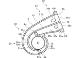
- FIG. 2 is a cross-sectional view taken along the line AA of the turbine housing shown in FIG.
- FIG. 3 is a schematic perspective view of the turbine housing as viewed from the wastegate port side.
- FIG. 4 is a sectional view taken along the line AA of the turbine housing in the comparative example.
- FIG. 5 is a diagram for explaining the total throat area of the turbine impeller.
- FIG. 6 is a diagram for explaining an inner diameter side throat area and an outer diameter side throat area of the turbine impeller.
- FIG. 7 is a cross-sectional view taken along the line AA of the turbine housing in the modified example.
- the supercharger TC includes a supercharger main body 1.
- the turbocharger main body 1 includes a bearing housing 3, a turbine housing (housing) 5, and a compressor housing 7.
- the turbine housing 5 is connected to the left side of the bearing housing 3 by a fastening mechanism 9.
- the compressor housing 7 is connected to the right side of the bearing housing 3 by a fastening bolt 11.
- the turbine T includes a bearing housing 3 and a turbine housing 5.
- the centrifugal compressor C includes a bearing housing 3 and a compressor housing 7.
- a protrusion 3a is provided on the outer peripheral surface of the bearing housing 3.
- the protrusion 3a is provided on the turbine housing 5 side.
- the protrusion 3 a projects in the radial direction of the bearing housing 3.
- a protrusion 5 a is provided on the outer peripheral surface of the turbine housing 5.
- the protrusion 5a is provided on the bearing housing 3 side.
- the protrusion 5 a projects in the radial direction of the turbine housing 5.
- the bearing housing 3 and the turbine housing 5 are band-fastened by the fastening mechanism 9.
- the fastening mechanism 9 is composed of, for example, a G coupling.
- the fastening mechanism 9 holds the protrusions 3a and 5a.
- a bearing hole 3b is formed in the bearing housing 3.
- the bearing hole 3b penetrates in the left-right direction of the supercharger TC.
- the bearing hole 3b rotatably supports the shaft 13 via a slide bearing.
- a turbine impeller 15 is provided at the left end of the shaft 13.
- the turbine impeller 15 is arranged in the turbine housing 5.
- the turbine impeller 15 is rotatably housed in the turbine housing 5.
- a compressor impeller 17 is provided at the right end of the shaft 13.
- the compressor impeller 17 is arranged in the compressor housing 7.
- the compressor impeller 17 is rotatably housed in the compressor housing 7.
- An intake port 19 is formed in the compressor housing 7.
- the intake port 19 opens on the right side of the supercharger TC.
- the intake port 19 is connected to an air cleaner (not shown).
- a diffuser flow path 21 is formed by the facing surfaces of the bearing housing 3 and the compressor housing 7.
- the diffuser flow path 21 pressurizes the air.
- the diffuser flow path 21 is formed in an annular shape.
- the diffuser flow passage 21 communicates with the intake port 19 via the compressor impeller 17 inside the shaft 13 in the radial direction.
- a compressor scroll passage 23 is formed in the compressor housing 7.
- the compressor scroll flow path 23 is formed in an annular shape.
- the compressor scroll flow path 23 is located, for example, radially outside the shaft 13 with respect to the diffuser flow path 21.
- the compressor scroll flow path 23 communicates with the intake port of an engine (not shown) and the diffuser flow path 21.
- the intake air is pressurized and accelerated in the process of flowing between the blades of the compressor impeller 17.
- the pressurized and accelerated air is pressurized in the diffuser flow passage 21 and the compressor scroll flow passage 23.
- the pressurized air is guided to the intake port of the engine.
- the exhaust flow path 25, the accommodating portion 27, and the exhaust flow path 29 are formed in the turbine housing 5.
- the discharge flow path 25 opens on the left side of the supercharger TC.
- the exhaust flow path 25 is connected to an exhaust gas purification device (not shown).
- the discharge flow path 25 communicates with the housing portion 27.
- the discharge flow path 25 is continuous with the accommodating portion 27 in the rotation axis direction of the turbine impeller 15.
- the housing portion 27 houses the turbine impeller 15.
- the exhaust flow path 29 is arranged on the radial outside of the accommodating portion 27 (turbine impeller 15).
- the exhaust flow path 29 communicates with the housing portion 27.
- the exhaust passage 29 is continuous with the housing portion 27 in the radial direction of the turbine impeller 15.
- FIG. 2 is a sectional view of the turbine housing 5 shown in FIG. 1 taken along the line AA. In FIG. 2, only the outer circumference of the turbine impeller 15 is shown by a circle. As shown in FIG. 2, an exhaust passage 29 is formed radially outside the housing portion 27 (turbine impeller 15 ). The exhaust passage 29 includes a communication portion 31, a turbine scroll passage 33, an exhaust introduction port 35, and an exhaust introduction passage 37.
- the communication part 31 is formed in an annular shape around the entire circumference of the accommodation part 27.
- the turbine scroll flow path 33 is located, for example, radially outside the turbine impeller 15 with respect to the communication portion 31.
- the turbine scroll flow path 33 is formed in an annular shape over the entire circumference of the communication portion 31 (accommodation portion 27).
- the communication section 31 communicates the accommodating section 27 with the turbine scroll flow path 33.
- the exhaust introduction port 35 opens outside the turbine housing 5. Exhaust gas discharged from an engine exhaust manifold (not shown) is introduced into the exhaust introduction port 35.
- An exhaust introduction passage 37 is formed between the exhaust introduction port 35 and the turbine scroll passage 33.
- the exhaust introduction path 37 connects the exhaust introduction port 35 and the turbine scroll flow path 33.
- the exhaust gas introduction path 37 is formed in a straight line, for example.
- the exhaust introduction path 37 guides the exhaust gas introduced from the exhaust introduction port 35 to the turbine scroll flow path 33.
- the turbine scroll passage 33 guides the exhaust gas introduced from the exhaust introduction passage 37 to the housing portion 27 via the communication portion 31.
- the exhaust passage 29 includes the exhaust introduction port 35, the exhaust introduction passage 37, the turbine scroll passage 33, and the communication portion 31.
- the exhaust flow path 29 extends from the exhaust introduction port 35 to the communication portion 31.
- a bypass passage 39 is formed in the turbine housing 5.
- the inlet end OP opens in the exhaust flow path 29, and the outlet end (wastegate port WP described later) opens in the exhaust flow path 25 (see FIG. 1). More specifically, in the bypass flow passage 39, the inlet end OP is opened to the exhaust introduction passage 37, and the outlet end is opened to the discharge flow passage 25.
- the bypass flow passage 39 connects (connects) the exhaust introduction passage 37 and the discharge passage 25.
- a wastegate port WP (see FIG. 1) is formed at the outlet end of the bypass flow path 39.
- a wastegate valve WV (see FIG. 1) capable of opening and closing the wastegate port WP is arranged at the outlet end of the bypass flow path 39.
- the waste gate valve WV is arranged in the discharge flow path 25.
- the bypass flow path 39 bypasses a part of the exhaust gas flowing through the exhaust introduction path 37 and bypasses the accommodating portion 27 (turbine impeller 15) to discharge the exhaust flow path 25. Leak to.
- a partition plate 41 is formed on the turbine housing 5.
- the partition plate 41 is arranged in the exhaust passage 29. More specifically, the partition plate 41 is arranged in the exhaust gas introducing port 35, the exhaust gas introducing passage 37, and the turbine scroll passage 33.
- the partition plate 41 is connected to the exhaust introduction port 35, the exhaust introduction path 37, and the inner surface of the turbine scroll flow path 33 in the rotation axis direction of the turbine impeller 15 (hereinafter, also referred to as the lateral direction of the partition plate 41). Will be done.
- the partition plate 41 extends in a direction away from the exhaust gas introduction port 35.
- the partition plate 41 extends along the exhaust passage 29.
- the partition plate 41 extends along the exhaust flow direction in which the exhaust gas flows (hereinafter, also referred to as the longitudinal direction of the partition plate 41).
- the upstream side in the exhaust flow direction is simply referred to as an upstream side
- the downstream side in the exhaust flow direction is simply referred to as a downstream side.
- the partition plate 41 has an upstream end arranged at the exhaust introduction port 35 and a downstream end arranged at a position (boundary) between the turbine scroll passage 33 and the communication portion 31.
- the partition plate 41 partitions (divides) the exhaust flow path 29 in the radial direction of the turbine impeller 15 (hereinafter, simply referred to as the radial direction).
- the exhaust flow path 29 is divided into an inner diameter side exhaust flow path (first exhaust flow path) 29a and an outer diameter side exhaust flow path (second exhaust flow path) 29b by a partition plate 41.
- the inner diameter side exhaust flow path 29a is located radially inside the turbine impeller 15 with respect to the outer diameter side exhaust flow path 29b.
- the inner diameter side exhaust flow path 29a is formed so as to be radially aligned with the outer diameter side exhaust flow path 29b.
- the outer diameter side exhaust flow path 29b has a longer flow path length than the inner diameter side exhaust flow path 29a.
- the partition plate 41 divides the exhaust introduction port 35 in the radial direction.
- the exhaust gas introducing port 35 is divided by a partition plate 41 into an inner diameter side exhaust gas introducing port 35a and an outer diameter side exhaust gas introducing port 35b.
- the inner diameter side exhaust introduction port 35a is located radially inside the turbine impeller 15 with respect to the outer diameter side exhaust introduction port 35b.
- the inner diameter side exhaust introduction port 35a is formed so as to be radially aligned with the outer diameter side exhaust introduction port 35b.
- the exhaust manifold (not shown) includes two (plural) divided passages.
- the two dividing paths are connected to the inner diameter side exhaust introduction port 35a and the outer diameter side exhaust introduction port 35b, respectively.
- Exhaust gas discharged from an engine (not shown) passes through two dividing paths of the exhaust manifold and is introduced into the inner diameter side exhaust introduction port 35a and the outer diameter side exhaust introduction port 35b. Of the exhaust gas flowing through the two dividing paths, one is introduced into the inner diameter side exhaust introduction port 35a, and the other is introduced into the outer diameter side exhaust introduction port 35b.
- the partition plate 41 divides the exhaust introduction path 37 in the radial direction.
- the exhaust gas introduction path 37 is divided by a partition plate 41 into an inner diameter side exhaust gas introduction path 37a and an outer diameter side exhaust gas introduction path 37b.
- the inner diameter side exhaust introduction passage 37a is located radially inside the turbine impeller 15 with respect to the outer diameter side exhaust introduction passage 37b.
- the inner diameter side exhaust introduction passage 37a is formed side by side with the outer diameter side exhaust introduction passage 37b in the radial direction of the turbine impeller 15.
- the inner diameter side exhaust introduction path 37a communicates with the inner diameter side exhaust introduction port 35a.
- the outer diameter side exhaust introduction path 37b communicates with the outer diameter side exhaust introduction port 35b.
- FIG. 3 is a schematic perspective view of the turbine housing 5 as viewed from the wastegate port WP side.
- the waste gate valve WV is not shown.
- a partition wall 43 is formed in the bypass channel 39.
- One end of the partition wall 43 is located at the inlet end OP (see FIG. 2) of the bypass flow path 39, and the other end is located at the outlet end (wastegate port WP) of the bypass flow path 39.
- the partition wall 43 extends along the exhaust flow direction in which the exhaust gas flows through the bypass flow path 39 (hereinafter, also referred to as the longitudinal direction of the partition wall 43).
- the partition wall 43 is connected to the inner surface of the bypass flow path 39 in the lateral direction D orthogonal to the longitudinal direction of the partition wall 43.
- the partition wall 43 divides the bypass channel 39.
- the bypass flow path 39 is divided into an inner diameter side bypass flow path (first bypass flow path) 39a and an outer diameter side bypass flow path (second bypass flow path) 39b by the partition wall 43.
- the inner diameter side bypass flow path 39a communicates with the inner diameter side exhaust introduction path 37a.
- the inner diameter side bypass flow passage 39a connects the inner diameter side exhaust introduction passage 37a and the discharge flow passage 25 (see FIGS. 1 and 3).
- the inner diameter side bypass flow path 39a guides a part of the exhaust gas flowing through the inner diameter side exhaust introduction path 37a to the wastegate port WP (see FIGS. 1 and 3).
- the outer diameter side bypass flow passage 39b communicates with the outer diameter side exhaust introduction passage 37b.
- the outer diameter side bypass flow path 39b connects the outer diameter side exhaust introduction path 37b and the discharge flow path 25.
- the outer diameter side bypass flow passage 39b guides a part of the exhaust gas flowing through the outer diameter side bypass flow passage 39b to the waste gate port WP.
- the partition plate 41 divides the turbine scroll passage 33 in the radial direction.
- the turbine scroll passage 33 is divided by the partition plate 41 into an inner diameter side turbine scroll passage 33a and an outer diameter side turbine scroll passage 33b.
- the inner diameter side turbine scroll flow path 33a is located radially inside the outer diameter side turbine scroll flow path 33b.
- the inner diameter side turbine scroll flow path 33a is formed so as to be radially aligned with the outer diameter side turbine scroll flow path 33b.
- the inner diameter side turbine scroll passage 33a communicates with the inner diameter side exhaust introduction passage 37a.
- the outer diameter side turbine scroll passage 33b communicates with the outer diameter side exhaust introduction passage 37b.
- the inner diameter side turbine scroll passage 33a becomes smaller in width in the radial direction as it goes away from the inner diameter side exhaust introduction passage 37a. That is, the inner diameter side turbine scroll flow path 33a becomes smaller in the radial direction from the upstream side to the downstream side.
- the outer diameter side turbine scroll passage 33b becomes smaller in width in the radial direction as it goes away from the outer diameter side exhaust introduction passage 37b. That is, the width of the outer diameter side turbine scroll flow path 33b in the radial direction decreases from the upstream side to the downstream side.
- the communication part 31 communicates with the inner diameter side turbine scroll passage 33a on the left half circumference in FIG.
- a portion of the communication portion 31 that communicates with the inner diameter side turbine scroll passage 33a is referred to as a first communication portion 31a.
- the communication portion 31 communicates with the outer diameter side turbine scroll passage 33b on the right half circumference in FIG.
- a portion of the communication portion 31 that communicates with the outer diameter side turbine scroll passage 33b is referred to as a second communication portion 31b.
- the accommodating portion 27 communicates with the first communicating portion 31a on the left half circumference in FIG.
- the first communication portion 31a is located between the inner diameter side turbine scroll flow path 33a and the accommodating portion 27.
- the accommodating portion 27 communicates with the second communicating portion 31b in the right half circumference in FIG.
- the second communication portion 31b is located between the outer diameter side turbine scroll flow path 33b and the accommodating portion 27.
- the housing portion 27 communicates with the inner diameter side exhaust flow path 29a on the left half circumference in FIG.
- the accommodating portion 27 communicates with the outer diameter side exhaust flow path 29b on the right half circumference in FIG.
- the position of the accommodating portion 27 communicating with the inner diameter side exhaust flow path 29a differs from the position communicating with the outer diameter side exhaust flow path 29b in the circumferential direction of the turbine impeller 15.
- the position where the accommodating portion 27 communicates with the inner diameter side turbine scroll flow path 33a via the first communication portion 31a communicates with the outer diameter side turbine scroll flow path 33b via the second communication portion 31b. And in the circumferential direction of the turbine impeller 15.
- the turbine housing 5 is formed with a first tongue portion 45a and a second tongue portion 45b.
- the first tongue portion 45a is formed at an end portion on the downstream side of the partition plate 41 (that is, an end portion on the side separated from the exhaust introduction port 35).
- the first tongue portion 45a is provided at a position facing the downstream end portion (downstream end) of the inner diameter side turbine scroll passage 33a.
- the first tongue portion 45a partitions the inner diameter side turbine scroll flow path 33a and the outer diameter side turbine scroll flow path 33b.
- the second tongue portion 45b is provided at a position facing the downstream end (downstream end) of the outer diameter side turbine scroll flow path 33b.
- the second tongue portion 45b partitions the outer diameter side turbine scroll flow path 33b and the inner diameter side turbine scroll flow path 33a.
- the phase of the first tongue portion 45a in the rotation direction of the turbine impeller 15 is approximately 180 degrees out of phase with respect to the second tongue portion 45b. That is, the first tongue portion 45a and the second tongue portion 45b are arranged at equal intervals in the rotation direction of the turbine impeller 15. However, the first tongue portion 45a may have a phase (position) different from that of the second tongue portion 45b in the rotation direction of the turbine impeller 15. The phase shift of the first tongue portion 45a with respect to the second tongue portion 45b does not have to be approximately 180 degrees. That is, the first tongue portion 45a and the second tongue portion 45b may be arranged at irregular intervals in the rotation direction of the turbine impeller 15. The first tongue portion 45a and the second tongue portion 45b are radially opposed to the turbine impeller 15.
- the exhaust gas discharged from the exhaust manifold of the engine (not shown) is guided to the exhaust flow path 25 via the exhaust flow path 29 and the accommodating portion 27.
- the exhaust gas guided to the discharge flow path 25 rotates the turbine impeller 15 in the distribution process.
- the rotational force of the turbine impeller 15 is transmitted to the compressor impeller 17 via the shaft 13.
- the air pressure is increased as described above. In this way, air is guided to the intake port of the engine.
- the inner diameter side exhaust passage 29a and the outer diameter side exhaust passage 29b may have different passage cross-sectional areas due to layout restrictions.
- the flow passage cross-sectional areas of the inner diameter side exhaust flow passage 29a and the outer diameter side exhaust flow passage 29b are the same as those of the inner diameter side turbine scroll flow passage 33a and the outer diameter side turbine scroll flow passage 33b. When compared at positions where the distances from the end (tongue) are the same, they are different from each other.
- the flow passage cross-sectional area of the inner diameter side exhaust flow passage 29a is the outer diameter side when compared at a position where the distances from the end portions (tongues) of the inner diameter side turbine scroll flow passage 33a and the outer diameter side turbine scroll flow passage 33b are equal. It is larger than the flow passage cross-sectional area of the exhaust flow passage 29b.
- the flow passage cross-sectional area that is the smallest in the portion of the inner diameter side exhaust flow passage (first exhaust flow passage) 29a facing the second tongue portion 45b is defined as the first exhaust minimum area Aa.
- a flow passage cross-sectional area that is the smallest in the portion of the outer diameter side exhaust flow passage (second exhaust flow passage) 29b facing the first tongue portion 45a is defined as a second exhaust minimum area Ab.
- the first exhaust minimum area Aa is larger than the second exhaust minimum area Ab.
- the second minimum exhaust area Ab is smaller than the first minimum exhaust area Aa.
- the present invention is not limited to this.
- the cross-sectional position where the flow passage cross-sectional area is the smallest (first exhaust minimum area Aa) in the portion of the inner diameter side exhaust flow passage 29a facing the second tongue portion 45b is the first cross-sectional position.
- the cross-sectional position where the flow passage cross-sectional area is the smallest (second exhaust minimum area Ab) in the portion of the outer diameter side exhaust flow passage 29b facing the first tongue portion 45a is referred to as the second cross-sectional position.
- the inner diameter side exhaust flow path 29a and the outer diameter side exhaust flow path 29a are located at a cross section position deviated by a predetermined distance toward the communication portion 31 side (or the exhaust introduction port 35 side).
- the flow passage cross-sectional areas of 29b may be different from each other.
- FIG. 4 is a sectional view taken along line AA of the turbine housing 105 in the comparative example.
- the turbine housing 105 includes a bypass passage 139.
- the turbine housing 105 in the comparative example has the same configuration as the turbine housing 5 in the present embodiment except for the bypass passage 139.
- the bypass flow path 139 includes an inner diameter side bypass flow path 139a and an outer diameter side bypass flow path 139b.
- the flow path cross-sectional areas of the inner diameter side bypass flow path 139a and the outer diameter side bypass flow path 139b are substantially the same.
- the turbine housing 105 has a first minimum exhaust area Aa and a second minimum exhaust area Ab different from each other.
- the wastegate valve WV (see FIG. 1) is closed, the exhaust gas flows through the exhaust flow path 29 without flowing through the bypass flow path 139. At this time, the exhaust gas flows through the exhaust flow path 29 at a flow rate corresponding to the flow path cross-sectional area of the inner diameter side exhaust flow path 29a and the outer diameter side exhaust flow path 29b. Therefore, the flow rate of the exhaust gas flowing through the inner diameter side exhaust flow channel 29a (hereinafter, also simply referred to as the inner diameter side flow rate) and the flow rate of the exhaust gas flowing through the outer diameter side exhaust flow channel 29b (hereinafter, simply referred to as the outer diameter side flow rate). There is a flow rate difference.
- the exhaust gas flows through the exhaust flow path 29 and the bypass flow path 139.
- the exhaust gas has a flow rate corresponding to the flow passage cross-sectional areas of the inner diameter side exhaust flow passage 29a, the outer diameter side exhaust flow passage 29b, the inner diameter side bypass flow passage 139a, and the outer diameter side bypass flow passage 139b. It flows through the passage 29 and the bypass passage 139.
- the flow passage cross-sectional areas of the inner diameter side bypass flow passage 139a and the outer diameter side bypass flow passage 139b are substantially the same.
- the flow rate of the exhaust gas flowing through the inner diameter side exhaust flow path 29a and the inner diameter side bypass flow path 139a (hereinafter, also simply referred to as the inner diameter side flow rate) and the outer diameter side exhaust flow path 29b and the outer diameter side bypass flow path 139b
- the flow rate difference between the flow rate of the circulated exhaust gas (hereinafter, also simply referred to as the outer diameter side flow rate).
- the flow rate difference between the inner diameter side flow rate and the outer diameter side flow rate when the wastegate valve WV (see FIG. 1) is opened is the inner diameter side flow rate and the outer diameter side flow rate when the wastegate valve WV is closed. Is roughly equal to the flow rate difference of.
- the engine back pressure may vary when the wastegate valve WV is open, which may reduce the supercharging performance of the turbocharger TC.
- the flow passage cross-sectional areas of the inner diameter side bypass flow passage 39a and the outer diameter side bypass flow passage 39b are different from each other.
- the flow passage cross-sectional areas of the inner diameter side bypass flow passage 39a and the outer diameter side bypass flow passage 39b are such that the inner diameter side bypass flow passage 39a and the outer diameter side bypass flow passage 39b have the same distance from the waste gate port WP. Compared with each other, they are different from each other.
- the flow passage cross-sectional area of the inner diameter side bypass flow passage 39a is the outer diameter.
- the flow passage cross-sectional area of the outer diameter side bypass flow passage 39b is larger than the flow passage cross sectional area of the inner diameter side bypass flow passage 39a. More specifically, the opening area of the inlet end OP of the inner diameter side bypass flow path 39a is smaller than the opening area of the inlet end OP of the outer diameter side bypass flow path 39b.
- the inner diameter side bypass minimum area (first bypass minimum area) Ba having the smallest flow path cross-sectional area of the inner diameter side bypass flow path 39a is the flow path disconnection of the outer diameter side bypass flow path 39b. It is smaller than the outer diameter side bypass minimum area (second bypass minimum area) Bb that minimizes the area.
- the inner diameter side bypass minimum area Ba is, for example, the opening area of the waste gate port WP of the inner diameter side bypass flow passage 39a.
- the outer diameter side bypass minimum area Bb is, for example, the opening area of the waste gate port WP of the outer diameter side bypass flow passage 39b. That is, the opening area of the wastegate port WP of the inner diameter side bypass flow path 39a is smaller than the opening area of the wastegate port WP of the outer diameter side bypass flow path 39b.
- the flow passage cross-sectional areas of the inner diameter side exhaust flow passage 29a and the outer diameter side exhaust flow passage 29b are different from each other.
- the flow passage cross-sectional area of the inner diameter side exhaust flow passage 29a (first exhaust minimum area Aa) is larger than the flow passage cross sectional area of the outer diameter side exhaust flow passage 29b (second exhaust minimum area Ab).
- the flow passage cross-sectional area of the outer diameter side exhaust flow passage 29b (second exhaust minimum area Ab) is smaller than the flow passage cross-sectional area of the inner diameter side exhaust flow passage 29a (first exhaust minimum area Aa).
- the flow passage cross-sectional area of the inner diameter side bypass flow passage 39a (minimum inner diameter side bypass area Ba) is equal to the flow passage cross sectional area of the outer diameter side bypass flow passage 39b (outer diameter side It is smaller than the minimum bypass area Bb).
- the inner diameter side exhaust flow path 29a (first exhaust minimum area Aa) is larger than the outer diameter side exhaust flow path 29b (second exhaust minimum area Ab). That is, the inner diameter side bypass flow path 39a whose flow path cross-sectional area is smaller than the outer diameter side bypass flow path 39b is connected to the inner diameter side exhaust flow path 29a whose flow path cross-sectional area is larger than the outer diameter side exhaust flow path 29b. ..
- the wastegate valve WV (see FIG. 1) is closed, the exhaust gas flows through the exhaust flow path 29 without flowing through the bypass flow path 39. At this time, the exhaust gas flows through the exhaust flow path 29 at a flow rate corresponding to the flow path cross-sectional area of the inner diameter side exhaust flow path 29a and the outer diameter side exhaust flow path 29b. Therefore, when the waste gate valve WV is closed, a flow rate difference occurs between the inner diameter side flow rate and the outer diameter side flow rate.
- the exhaust gas flows through the exhaust flow path 29 and the bypass flow path 39.
- the exhaust gas has a flow rate corresponding to the flow passage cross-sectional areas of the inner diameter side exhaust flow passage 29a, the outer diameter side exhaust flow passage 29b, the inner diameter side bypass flow passage 39a, and the outer diameter side bypass flow passage 39b. It flows through the passage 29 and the bypass passage 39.
- an inner diameter side bypass flow passage 39a having a flow passage cross sectional area smaller than the outer diameter side bypass flow passage 39b is connected to the inner diameter side exhaust flow passage 29a having a flow passage cross sectional area larger than the outer diameter side exhaust flow passage 29b.
- the flow rate difference between the inner diameter side flow rate and the outer diameter side flow rate when the wastegate valve WV is open is the flow rate difference between the inner diameter side flow rate and the outer diameter side flow rate when the wastegate valve WV is closed. It becomes smaller. Therefore, the turbine housing 5 of the present embodiment can reduce variations in engine back pressure when the waste gate valve WV is open, and can suppress deterioration of supercharging performance of the supercharger TC.
- valve closed inner diameter side flow rate the flow rate of the exhaust gas flowing through the inner diameter side exhaust passage 29a when the waste gate valve WV (see FIG. 1) is closed.
- valve open inner diameter side flow rate the flow rate of the exhaust gas flowing through the inner diameter side exhaust passage 29a and the inner diameter side bypass passage 39a when the waste gate valve WV is in the open state.
- the flow rate of the exhaust gas flowing through the outer diameter side exhaust flow path 29b when the waste gate valve WV (see FIG. 1) is closed is called the outer diameter side flow rate when the valve is closed.
- the flow rate of the exhaust gas flowing through the outer diameter side exhaust flow path 29b and the outer diameter side bypass flow path 39b when the waste gate valve WV is closed is referred to as the valve open outer diameter side flow rate.
- the difference between the flow rate when the valve is open and the flow rate when the valve is open is called the flow rate difference when the valve is open.
- the flow rate difference between the inner diameter side flow rate when the valve is closed and the outer diameter side flow rate when the valve is closed is called the flow rate difference when the valve is closed.
- the flow path cross-sectional area of the inner diameter side exhaust flow path 29a is relatively large as compared with the flow path cross-sectional area of the outer diameter side exhaust flow path 29b.
- the flow path cross-sectional area of the inner diameter side bypass flow path 39a is relatively small as compared with the flow path cross-sectional area of the outer diameter side bypass flow path 39b. Therefore, the flow rate difference when the valve is open can be made smaller than the flow rate difference when the valve is closed. Therefore, the turbine housing 5 of the present embodiment can reduce variations in engine back pressure when the waste gate valve WV is open, and can suppress deterioration of supercharging performance of the supercharger TC.
- the effective area when the exhaust gas passes through the turbine impeller 15 via the inner diameter side exhaust flow path 29a is defined as the inner diameter side effective area Aaf.
- the effective area when the exhaust gas passes through the turbine impeller 15 via the outer diameter side exhaust flow path 29b is defined as the outer diameter side effective area Abf. Details of the inner diameter side effective area Aaf and the outer diameter side effective area Abf will be described later.
- the flow passage cross-sectional area of the inner diameter side exhaust flow passage 29a is Aa (in the present embodiment, the first exhaust minimum area Aa).
- the flow passage cross-sectional area of the outer diameter side exhaust flow passage 29b is set to Ab (the second minimum exhaust area Ab in the present embodiment).
- the flow passage cross-sectional area of the inner diameter side bypass flow passage 39a is Ba (in the present embodiment, the inner diameter side bypass minimum area Ba).
- the flow passage cross-sectional area of the outer diameter side bypass flow passage 39b is set to Bb (in the present embodiment, the outer diameter side bypass minimum area Bb).
- the total throat area of the turbine impeller 15 is Ai.
- the throat area (hereinafter, referred to as the inner diameter side throat area) of the portion of the turbine impeller 15 facing the inner diameter side exhaust flow path 29a is referred to as Aia.
- the throat area (hereinafter, referred to as the outer diameter side throat area) of the portion of the turbine impeller 15 facing the outer diameter side exhaust flow path 29b is defined as Aib. Details of the total throat area Ai, the inner diameter side throat area Aia, and the outer diameter side throat area Aib will be described later.
- ⁇ a be the central angle of the facing portion (inner diameter side throat area Aia) facing the inner diameter side exhaust flow path 29a of the turbine impeller 15.
- ⁇ b be the central angle of the facing portion (outer diameter side throat area Aib) facing the outer diameter side exhaust flow path 29b of the turbine impeller 15. Details of the central angles ⁇ a and ⁇ b will be described later.
- the inner diameter side effective area Aaf is derived by the following equation (1). ...(1)
- the inner diameter side throat area Aia is derived by the following formula (1a). ...(1a)
- the total throat area Ai of the turbine impeller 15 is approximately derived by the following formula (1b). ...(1b)
- FIG. 5 is a diagram for explaining the total throat area Ai of the turbine impeller 15.
- the turbine impeller 15 has a hub 15a and blades 15b.
- the hub 15a is provided on the shaft 13 (see FIG. 1).
- the hub 15a has a shape in which the diameter is smaller toward the left side in FIG. 5 and the diameter is larger toward the right side in FIG.
- the blade 15b is provided on the outer peripheral surface of the hub 15a.
- a plurality of blades 15b are provided so as to be separated in the circumferential direction of the hub 15a.
- the outlet shroud diameter of the turbine impeller 15 is "D4s", and the outlet hub diameter of the turbine impeller 15 is "D4h”. Further, the blade angle on the outlet shroud side of the turbine impeller 15 is set to " ⁇ 4s".
- the total throat area Ai of the turbine impeller 15 is derived by the above equation (1b).
- FIG. 6 is a diagram for explaining the inner diameter side throat area Aia and the outer diameter side throat area Aib of the turbine impeller 15.
- the turbine impeller 15 includes a facing portion FS1 that faces the inner diameter side exhaust passage 29a.
- the inner diameter side throat area Aia is the throat area of the facing portion FS1 of the turbine impeller 15.
- the central angle ⁇ a is the central angle of the facing portion FS1 (inner diameter side throat area Aia) of the turbine impeller 15.
- the central angle ⁇ a is approximately equal to the phase shift between the first tongue portion 45a and the second tongue portion 45b on the inner diameter side exhaust flow path 29a side.
- the turbine impeller 15 includes an opposing portion FS2 facing the outer diameter side exhaust flow path 29b.
- the outer diameter side throat area Aib is the throat area of the facing portion FS2 of the turbine impeller 15.
- the central angle ⁇ b is the central angle of the facing portion FS2 (outer diameter side throat area Aib) of the turbine impeller 15.
- the central angle ⁇ b is approximately equal to the phase shift between the first tongue portion 45a and the second tongue portion 45b on the outer diameter side exhaust flow path 29b side.
- the central angle ⁇ a is approximately equal to the central angle ⁇ b.
- the outer diameter side effective area Abf is derived by the following equation (2). ...(2)
- the inner diameter side effective area (first effective area) Aaf is the flow path cross-sectional area (first exhaust minimum area Aa) of the inner diameter side exhaust flow path 29a and the throat area of the turbine impeller 15. It is an area derived from the inner diameter side throat area Aia).
- the outer diameter side effective area (second effective area) Abf is the flow path cross-sectional area (second exhaust minimum area Ab) of the outer diameter side exhaust flow path 29b and the throat of the turbine impeller 15. It is an area derived from the area (outer diameter side throat area Aib).
- the difference between the inner diameter side effective area Aaf and the outer diameter side effective area Abf is the sum of the inner diameter side effective area Aaf and the inner diameter side bypass minimum area Ba, and the outer diameter side effective area Abf and the outer diameter side bypass minimum. It is larger than the difference from the total area Bb. That is, compared with the difference between the inner diameter side effective area Aaf and the outer diameter side effective area Abf, the total of the inner diameter side effective area Aaf and the inner diameter side bypass minimum area Ba, and the outer diameter side effective area Abf and the outer diameter side bypass minimum area Bb. The difference from the sum of is smaller.
- the difference between the inner diameter side effective area Aaf and the outer diameter side effective area Abf satisfies the condition of the following expression (3). ...(3)
- the flow rate of the exhaust gas flowing through the inner diameter side exhaust flow path 29a is derived by the inner diameter side effective area Aaf.
- the flow rate of the exhaust gas flowing through the inner diameter side exhaust flow path 29a and the inner diameter side bypass flow path 39a is the inner diameter side effective area Aaf and the inner diameter side bypass. Derived by the minimum area Ba.
- the flow rate of the exhaust gas flowing through the outer diameter side exhaust flow path 29b is the outer diameter side effective area Abf. Derived by.
- the flow rate of the exhaust gas flowing through the outer diameter side exhaust flow path 29b and the outer diameter side bypass flow path 39b is the outer diameter side effective area Abf.
- the outer diameter side bypass minimum area Bb is the outer diameter side bypass minimum area Bb.
- the left side of the above equation (3) represents a value according to the flow rate difference between the inner diameter side flow rate when the valve is open and the outer diameter side flow rate when the valve is open (flow rate difference when the valve is open).
- the right side of the above equation (3) represents a value according to the flow rate difference between the valve-closed inner diameter side flow rate and the valve-closed outer diameter side flow rate (valve-closed flow rate difference). Therefore, the above equation (3) shows a condition that the flow rate difference when the valve is open is smaller than the flow rate difference when the valve is closed.
- the flow passage cross-sectional areas of the inner diameter side bypass flow passage 139a (see FIG. 4) and the outer diameter side bypass flow passage 139b (see FIG. 4) of the comparative example are substantially the same. That is, the inner diameter side bypass minimum area Ba is substantially the same as the outer diameter side bypass minimum area Bb. At this time, the left side of the above equation (3) becomes equal to the right side. Therefore, the flow rate difference when the valve is open is substantially the same as the flow rate difference when the valve is closed. As described above, since the turbine housing 105 of the comparative example does not satisfy the condition of the above expression (3), it is difficult to reduce the variation in the engine back pressure when the waste gate valve WV is open.
- the inner diameter side bypass minimum area Ba of this embodiment is smaller than the outer diameter side bypass minimum area Bb.
- the first exhaust minimum area Aa is larger than the second exhaust minimum area Ab.
- the inner diameter side throat area Aia and the outer diameter side throat area Aib are approximately equal. Therefore, the inner diameter side effective area Aaf is larger than the outer diameter side effective area Abf.
- the left side of the above equation (3) is smaller than the right side. Therefore, the flow rate difference when the valve is open is smaller than the flow rate difference when the valve is closed.
- the turbine housing 5 of the present embodiment satisfies the condition of the above expression (3), so that it is possible to reduce variations in the engine back pressure when the waste gate valve WV is open.
- the left side of the above equation (3) may become larger than the right side.
- the flow rate difference when the valve is open becomes larger than the flow rate difference when the valve is closed.
- the waste gate valve WV is changed from the closed state to the open state, there is a possibility that variations in engine back pressure increase. Therefore, in the turbine housing 5 of the present embodiment, it is preferable to set each flow passage cross-sectional area so as to satisfy the condition of the above expression (3).
- the turbine T is incorporated in the turbocharger TC.
- the present invention is not limited to this, and the turbine T may be incorporated in a device other than the supercharger TC or may be a single unit.
- first exhaust minimum area Aa is larger than the second exhaust minimum area Ab.
- present invention is not limited to this, and the first exhaust minimum area Aa may be smaller than the second exhaust minimum area Ab.
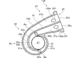
- FIG. 7 is a sectional view taken along line AA of the turbine housing 205 in the modified example.
- the turbine housing 205 includes an exhaust flow path 129 and a bypass flow path 239.
- the exhaust flow path 129 includes an inner diameter side exhaust flow path 129a and an outer diameter side exhaust flow path 129b.
- the inner diameter side exhaust flow path 129a has an inner diameter side turbine scroll flow path 133a.
- the outer diameter side exhaust passage 129b has an outer diameter side turbine scroll passage 133b.
- the turbine housing 205 in the modified example is the same as the turbine housing 5 in the above-described embodiment except for the configuration other than the inner diameter side turbine scroll passage 133a, the outer diameter side turbine scroll passage 133b, and the bypass passage 239.
- the outer diameter side turbine scroll flow passage 133b has a longer flow passage length than the inner diameter side turbine scroll flow passage 133a. That is, the outer diameter side exhaust flow path 129b has a longer flow path length than the inner diameter side exhaust flow path 129a. In this case, the outer diameter side exhaust flow path 129b has a larger pressure loss than the inner diameter side exhaust flow path 129a. Therefore, it is preferable that the outer diameter side exhaust passage 129b has a larger passage sectional area than the inner diameter side exhaust passage 129a.
- the flow passage cross-sectional area of the outer diameter side exhaust flow passage (first exhaust flow passage) 129b is calculated from the flow passage cross sectional area of the inner diameter side exhaust flow passage (second exhaust flow passage) 129a. It's getting bigger. That is, the second minimum exhaust area Ab is larger than the first minimum exhaust area Aa.
- the flow passage cross-sectional area of the inner diameter side exhaust flow passage 129a and the outer diameter side exhaust flow passage 129b which has the longer flow passage length, is equal to that of the inner diameter side exhaust flow passage 129a and the outer diameter side exhaust flow passage 129b. It may be larger than the flow path cross-sectional area of the shorter path. As a result, the pressure loss of the inner diameter side exhaust flow path 129a and the outer diameter side exhaust flow path 129b, whichever has the longer flow path length, can be reduced.
- the modified bypass flow path 239 has an inner diameter side bypass flow path 239a and an outer diameter side bypass flow path 239b.
- the flow passage cross-sectional area of the inner diameter side bypass flow passage (second bypass flow passage) 239a is larger than the flow passage cross sectional area of the outer diameter side bypass flow passage (first bypass flow passage) 239b.
- the inner diameter side bypass minimum area Ba of the inner diameter side bypass flow passage 239a having the smallest flow passage cross-sectional area is the outer diameter side bypass minimum area of the outer diameter side bypass flow passage 239b having the smallest flow passage cross sectional area. It is larger than the area Bb.
- the flow passage cross-sectional area of the outer diameter side exhaust flow passage 129b is relatively larger than the flow passage cross sectional area of the inner diameter side exhaust flow passage 129a.
- the flow passage cross-sectional area of the outer diameter side bypass flow passage 239b is relatively smaller than the flow passage cross sectional area of the inner diameter side bypass flow passage 239a.
- the cross-sectional area of each of the exhaust flow path 129 and the bypass flow path 239 may be set so as to satisfy the condition of the above formula (3). As a result, the turbine housing 205 of the modified example can obtain the same effect as that of the above embodiment.
- the present disclosure can be used for turbines.
Landscapes
- Engineering & Computer Science (AREA)
- Mechanical Engineering (AREA)
- General Engineering & Computer Science (AREA)
- Chemical & Material Sciences (AREA)
- Combustion & Propulsion (AREA)
- Supercharger (AREA)
- Physics & Mathematics (AREA)
- Fluid Mechanics (AREA)
Abstract
Description







Claims (5)
- タービンインペラを収容する収容部が形成されたハウジングと、
前記ハウジングに形成され、前記収容部と連通する第1排気流路と、
前記ハウジングに形成され、前記収容部と前記第1排気流路が連通する位置に対し、前記タービンインペラの周方向の異なる位置で前記収容部と連通し、前記第1排気流路の流路断面積よりも小さい流路断面積を有する第2排気流路と、
前記ハウジングに形成され、前記タービンインペラの軸方向において前記収容部と連通する排出流路と、
前記第1排気流路と前記排出流路とを接続する第1バイパス流路と、
前記第2排気流路と前記排出流路とを接続し、前記第1バイパス流路の流路断面積よりも大きい流路断面積を有する第2バイパス流路と、
を備えるタービン。 - 前記第2排気流路は、前記第1排気流路よりも流路長が長い請求項1に記載のタービン。
- 前記第1排気流路は、前記第2排気流路よりも流路長が長い請求項1に記載のタービン。
- 前記ハウジングのうち、前記第1排気流路の下流端に面する位置に設けられ、前記第1排気流路と前記第2排気流路とを区画する第1舌部と、
前記ハウジングのうち、前記第2排気流路の下流端に面する位置に設けられ、前記第2排気流路と前記第1排気流路とを区画する第2舌部と、
を備え、
前記第1排気流路の前記流路断面積は、前記第1排気流路のうち前記第2舌部に面する部位の中で流路断面積が最小となる第1排気最小面積であり、
前記第2排気流路の前記流路断面積は、前記第2排気流路のうち前記第1舌部に面する部位の中で流路断面積が最小となる第2排気最小面積であり、
前記第1バイパス流路の前記流路断面積は、前記第1バイパス流路のうち流路断面積が最小となる第1バイパス最小面積であり、
前記第2バイパス流路の前記流路断面積は、前記第2バイパス流路のうち流路断面積が最小となる第2バイパス最小面積であり、
前記第1排気最小面積と前記タービンインペラのスロート面積により導出される第1有効面積と、前記第2排気最小面積と前記タービンインペラのスロート面積により導出される第2有効面積との差に比べ、前記第1有効面積および前記第1バイパス最小面積の合計と、前記第2有効面積および前記第2バイパス最小面積の合計との差の方が小さい請求項1~3のいずれか1項に記載のタービン。 - 前記第1排気最小面積をAa、前記第2排気最小面積をAb、前記タービンインペラの総スロート面積をAi、前記タービンインペラのうち前記第1排気流路と対向する対向部位のスロート面積をAia、前記タービンインペラのうち前記第2排気流路と対向する対向部位のスロート面積をAib、前記タービンインペラのうち前記第1排気流路と対向する対向部位の中心角をθa、前記タービンインペラのうち前記第2排気流路と対向する対向部位の中心角をθb、前記第1有効面積をAaf、および、前記第2有効面積をAbfとした場合に、前記第1有効面積Aafは式(1)および式(1a)にて導出され、前記第2有効面積Abfは式(2)および式(2a)にて導出される請求項4記載のタービン。




Priority Applications (4)
| Application Number | Priority Date | Filing Date | Title |
|---|---|---|---|
| DE112019006976.4T DE112019006976B4 (de) | 2019-03-06 | 2019-09-02 | Turbine |
| JP2021503390A JP7151866B2 (ja) | 2019-03-06 | 2019-09-02 | タービン |
| CN201980093778.2A CN113544369B (zh) | 2019-03-06 | 2019-09-02 | 涡轮机 |
| US17/404,490 US11492916B2 (en) | 2019-03-06 | 2021-08-17 | Turbine |
Applications Claiming Priority (2)
| Application Number | Priority Date | Filing Date | Title |
|---|---|---|---|
| JP2019-040384 | 2019-03-06 | ||
| JP2019040384 | 2019-03-06 |
Related Child Applications (1)
| Application Number | Title | Priority Date | Filing Date |
|---|---|---|---|
| US17/404,490 Continuation US11492916B2 (en) | 2019-03-06 | 2021-08-17 | Turbine |
Publications (1)
| Publication Number | Publication Date |
|---|---|
| WO2020179107A1 true WO2020179107A1 (ja) | 2020-09-10 |
Family
ID=72337802
Family Applications (1)
| Application Number | Title | Priority Date | Filing Date |
|---|---|---|---|
| PCT/JP2019/034397 Ceased WO2020179107A1 (ja) | 2019-03-06 | 2019-09-02 | タービン |
Country Status (5)
| Country | Link |
|---|---|
| US (1) | US11492916B2 (ja) |
| JP (1) | JP7151866B2 (ja) |
| CN (1) | CN113544369B (ja) |
| DE (1) | DE112019006976B4 (ja) |
| WO (1) | WO2020179107A1 (ja) |
Families Citing this family (1)
| Publication number | Priority date | Publication date | Assignee | Title |
|---|---|---|---|---|
| JP7311029B2 (ja) | 2020-03-24 | 2023-07-19 | 株式会社Ihi | 過給機 |
Citations (5)
| Publication number | Priority date | Publication date | Assignee | Title |
|---|---|---|---|---|
| JPS61151040U (ja) * | 1985-03-13 | 1986-09-18 | ||
| JPS61178034U (ja) * | 1985-04-26 | 1986-11-06 | ||
| JPH0196428A (ja) * | 1987-10-09 | 1989-04-14 | Hitachi Ltd | 過給機の排気バイパス |
| US20180238226A1 (en) * | 2015-02-25 | 2018-08-23 | Kangyue Technology Co., Ltd. | Variable geometry wastegate turbine meeting the requirements of egr circulation |
| JP2018172989A (ja) * | 2017-03-31 | 2018-11-08 | 株式会社Ihi | 過給機 |
Family Cites Families (22)
| Publication number | Priority date | Publication date | Assignee | Title |
|---|---|---|---|---|
| JPS57137619A (en) | 1981-02-18 | 1982-08-25 | Hitachi Ltd | Exhaust bypass device of turbocharger for multi- cylinder engine |
| JPS59203821A (ja) | 1983-05-02 | 1984-11-19 | Honda Motor Co Ltd | タ−ボチヤ−ジヤ装置 |
| JPS618421A (ja) * | 1984-06-22 | 1986-01-16 | Toyota Motor Corp | タ−ボチヤ−ジヤの排気バイパス装置 |
| JPH065022B2 (ja) | 1985-07-18 | 1994-01-19 | マツダ株式会社 | 排気タ−ボ過給機付エンジン |
| JPS62279233A (ja) | 1986-05-28 | 1987-12-04 | Hitachi Ltd | 可変容量タ−ボチヤ−ジヤ |
| US5046317A (en) * | 1989-06-09 | 1991-09-10 | Allied-Signal Inc. | Wastegate valve for turbocharger |
| DE102004030703A1 (de) * | 2004-06-25 | 2006-03-09 | Daimlerchrysler Ag | Abgasturbolader für eine Hubkolben-Brennkraftmaschine und Hubkolben-Brennkraftmaschine |
| DE102004034070A1 (de) * | 2004-07-15 | 2006-02-09 | Daimlerchrysler Ag | Brennkraftmaschine mit einem Abgasturbolader |
| JP4548237B2 (ja) | 2005-06-17 | 2010-09-22 | トヨタ自動車株式会社 | ターボチャージャのツインスクロールタービンハウジング |
| GB0610691D0 (en) * | 2006-05-31 | 2006-07-12 | Cummins Turbo Technologies | Turbocharger with dual wastegate |
| JP2009287434A (ja) | 2008-05-28 | 2009-12-10 | Toyota Motor Corp | 内燃機関の排気還流装置 |
| JP5257193B2 (ja) * | 2009-03-26 | 2013-08-07 | マツダ株式会社 | 過給機付きエンジン |
| JP5665486B2 (ja) * | 2010-11-04 | 2015-02-04 | 三菱重工業株式会社 | ツインスクロール型ターボチャージャのタービンハウジング |
| JP5589934B2 (ja) * | 2011-04-05 | 2014-09-17 | 株式会社デンソー | タービン及びターボチャージャ |
| CN102383877A (zh) * | 2011-10-08 | 2012-03-21 | 康跃科技股份有限公司 | 可变几何的脉冲进气涡轮机的蜗壳装置 |
| US10227889B2 (en) * | 2015-02-05 | 2019-03-12 | Garrett Transportation I Inc. | Variable geometry nozzle for partitioned volute |
| KR20170067960A (ko) * | 2015-12-08 | 2017-06-19 | 현대자동차주식회사 | 차량의 터보차져 구조 |
| JP6754596B2 (ja) * | 2016-03-30 | 2020-09-16 | 三菱重工業株式会社 | 2ステージターボシステムおよび2ステージターボシステムの制御方法 |
| DE102017202211B4 (de) * | 2017-02-13 | 2021-01-21 | Volkswagen Aktiengesellschaft | Brennkraftmaschine |
| WO2018151267A1 (ja) * | 2017-02-16 | 2018-08-23 | 株式会社Ihi | 過給機 |
| JP6861126B2 (ja) | 2017-08-25 | 2021-04-21 | ニッタン株式会社 | 情報発信アダプタ |
| DE112020001851T5 (de) * | 2019-04-10 | 2021-12-30 | Ihi Corporation | Turbine und Turbolader |
-
2019
- 2019-09-02 JP JP2021503390A patent/JP7151866B2/ja active Active
- 2019-09-02 WO PCT/JP2019/034397 patent/WO2020179107A1/ja not_active Ceased
- 2019-09-02 CN CN201980093778.2A patent/CN113544369B/zh active Active
- 2019-09-02 DE DE112019006976.4T patent/DE112019006976B4/de active Active
-
2021
- 2021-08-17 US US17/404,490 patent/US11492916B2/en active Active
Patent Citations (5)
| Publication number | Priority date | Publication date | Assignee | Title |
|---|---|---|---|---|
| JPS61151040U (ja) * | 1985-03-13 | 1986-09-18 | ||
| JPS61178034U (ja) * | 1985-04-26 | 1986-11-06 | ||
| JPH0196428A (ja) * | 1987-10-09 | 1989-04-14 | Hitachi Ltd | 過給機の排気バイパス |
| US20180238226A1 (en) * | 2015-02-25 | 2018-08-23 | Kangyue Technology Co., Ltd. | Variable geometry wastegate turbine meeting the requirements of egr circulation |
| JP2018172989A (ja) * | 2017-03-31 | 2018-11-08 | 株式会社Ihi | 過給機 |
Also Published As
| Publication number | Publication date |
|---|---|
| JP7151866B2 (ja) | 2022-10-12 |
| JPWO2020179107A1 (ja) | 2021-12-09 |
| CN113544369B (zh) | 2023-04-04 |
| US11492916B2 (en) | 2022-11-08 |
| DE112019006976B4 (de) | 2026-01-08 |
| DE112019006976T5 (de) | 2021-11-18 |
| CN113544369A (zh) | 2021-10-22 |
| US20210372318A1 (en) | 2021-12-02 |
Similar Documents
| Publication | Publication Date | Title |
|---|---|---|
| JP6413980B2 (ja) | ターボチャージャの排気タービン | |
| JP5369723B2 (ja) | 遠心圧縮機 | |
| CN107542575B (zh) | 涡轮 | |
| WO2016035329A1 (ja) | ターボチャージャの排気タービン | |
| JP6780714B2 (ja) | 過給機 | |
| JP6922339B2 (ja) | 過給機 | |
| JP2016053352A (ja) | ターボチャージャの排気タービン | |
| JP7364082B2 (ja) | タービンおよび過給機 | |
| JP7151866B2 (ja) | タービン | |
| CN109469546B (zh) | 涡轮增压器 | |
| JP7491151B2 (ja) | タービンおよび過給機 | |
| JP2007023893A (ja) | ターボ過給機 | |
| WO2020209146A1 (ja) | タービンおよび過給機 | |
| JP7424540B2 (ja) | タービンおよび過給機 | |
| JP7232352B2 (ja) | コンプレッサおよび該コンプレッサを備えるターボチャージャ | |
| US12158099B2 (en) | Turbine and turbocharger | |
| JP7815931B2 (ja) | タービンおよび過給機 | |
| JP7566881B2 (ja) | タービン | |
| WO2024053148A1 (ja) | タービン | |
| WO2020050052A1 (ja) | 斜流タービンおよび過給機 | |
| JP2023131315A (ja) | 過給機 | |
| WO2022196234A1 (ja) | タービンおよび過給機 | |
| JP5392285B2 (ja) | タービン、及びこれを備えたターボチャージャ | |
| WO2025041333A1 (ja) | 過給機 |
Legal Events
| Date | Code | Title | Description |
|---|---|---|---|
| 121 | Ep: the epo has been informed by wipo that ep was designated in this application |
Ref document number: 19917669 Country of ref document: EP Kind code of ref document: A1 |
|
| ENP | Entry into the national phase |
Ref document number: 2021503390 Country of ref document: JP Kind code of ref document: A |
|
| WWE | Wipo information: entry into national phase |
Ref document number: 112019006976 Country of ref document: DE |
|
| WWP | Wipo information: published in national office |
Ref document number: 112019006976 Country of ref document: DE |
|
| 122 | Ep: pct application non-entry in european phase |
Ref document number: 19917669 Country of ref document: EP Kind code of ref document: A1 |
|
| WWG | Wipo information: grant in national office |
Ref document number: 112019006976 Country of ref document: DE |