WO2020179038A1 - 車両前部構造 - Google Patents
車両前部構造 Download PDFInfo
- Publication number
- WO2020179038A1 WO2020179038A1 PCT/JP2019/008970 JP2019008970W WO2020179038A1 WO 2020179038 A1 WO2020179038 A1 WO 2020179038A1 JP 2019008970 W JP2019008970 W JP 2019008970W WO 2020179038 A1 WO2020179038 A1 WO 2020179038A1
- Authority
- WO
- WIPO (PCT)
- Prior art keywords
- opening
- horn
- wall portion
- vehicle front
- fog
- Prior art date
- Legal status (The legal status is an assumption and is not a legal conclusion. Google has not performed a legal analysis and makes no representation as to the accuracy of the status listed.)
- Ceased
Links
Images



Classifications
-
- B—PERFORMING OPERATIONS; TRANSPORTING
- B60—VEHICLES IN GENERAL
- B60Q—ARRANGEMENT OF SIGNALLING OR LIGHTING DEVICES, THE MOUNTING OR SUPPORTING THEREOF OR CIRCUITS THEREFOR, FOR VEHICLES IN GENERAL
- B60Q5/00—Arrangement or adaptation of acoustic signal devices
Definitions
- the present invention relates to a vehicle front structure.
- Patent Document 1 describes a structure in which a horn is arranged behind a fog light in a vehicle.
- Patent Document 1 has a problem that the sound pressure of the sound generated by the horn is reduced by the fog lights.
- the present invention has been made in view of the above points, and an object of the present invention is to provide a vehicle front structure capable of suitably ensuring the sound pressure of the sound generated by the horn.
- a vehicle front structure of the present invention is a fog garnish having a fog light portion provided with a fog lamp, and an opening portion formed on a side of the fog light portion, and the opening. And a reflection plate attached to an edge of the opening and guiding a sound wave generated by the horn to the opening.
- the fog light is not in front of the horn and the reflection plate is provided, the sound pressure of the sound generated by the horn can be properly secured.
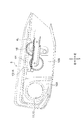
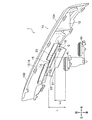
- FIG. 1 is a front view schematically showing a vehicle to which a vehicle front structure according to an exemplary embodiment of the present invention is applied. It is the elements on larger scale of FIG. It is a top view which shows typically the vehicle front part structure which concerns on embodiment of this invention. It is a side view which shows typically the vehicle front part structure which concerns on embodiment of this invention. It is a perspective view which shows typically the fog garnish and the reflection plate which concern on embodiment of this invention. It is sectional drawing which shows typically the assembly part of the fog garnish and the reflection plate which concern on embodiment of this invention. It is a sectional view showing typically the vehicles front part structure concerning the embodiment of the present invention. It is a perspective view which shows typically the reflection plate which concerns on embodiment of this invention.
- a vehicle front structure 1 includes a bumper face 2, a fog lamp 3, horns 4L and 4H, a fog garnish 10, and a reflection plate 20.
- the bumper face 2 is a metal or resin member that extends in the vehicle width direction at the front end of the vehicle and constitutes a part of the front surface of the vehicle.
- a hole 2a having a substantially rectangular shape when viewed from the front is formed at the end of the bumper face 2 in the vehicle width direction.
- the fog lamp 3 is an auxiliary traveling lamp that irradiates the front of the vehicle with light in order to ensure the driver's field of view during a heavy fog or the like.
- the fog lamp 3 is attached to the fog light portion 10A of the fog garnish 10.
- the horns 4L and 4H are devices that generate a warning sound in response to a driver's operation or the like.
- the horns 4L and 4H emit sound waves forward from a sound wave generating portion that has a circular shape when viewed from the front.
- the horn 4L arranged inside in the vehicle width direction generates a low-pitched sound (for example, a wavelength of 85.75 to 149.15 [mm]).
- Horn 4? The upper end of the horn 4? Is located at substantially the same height as the upper edge of the opening 13 described later.
- the lower end of the opening is located at a height lower than the lower edge of the opening 13.
- the horn 4H which is arranged on the outer side in the vehicle width direction, is provided behind and below the horn 4L, and generates a warning sound of high sound (for example, a wavelength of 72.97 to 123.69 [mm]).
- the upper end of the horn 4H is located at a height intermediate between the upper edge and the lower edge of the opening 13, and the lower end of the horn 4H is located at a height below the lower edge of the opening 13. ..
- the horns 4L and 4H are attached to a member (for example, a bulkhead or the like) provided behind the bumper face 2 and the fog garnish 10.
- the fog garnish 10 is a plate-shaped resin member having a substantially rectangular shape in a front view.
- the fog garnish 10 is curved and formed so as to go rearward as it goes outward in the vehicle width direction in a plan view.
- the fog garnish 10 is attached to the bumper face 2 so as to close the hole 2a (see FIG. 1).
- the outside of the fog garnish 10 in the vehicle width direction is a fog light portion 10A provided with the fog lamp 3, and the inside of the fog garnish 20 in the vehicle width direction is a horn portion 10B provided with horns 4H and 4L behind the fog garnish 20.
- the bumper face 2 is formed with a pair of holes 2a at both ends in the vehicle width direction, and the fog garnish 10 of the present invention is provided in one hole 2a (for example, on the right side or the driver's seat side). ..
- a fog garnish that is substantially left-right symmetric with the fog garnish 10 of the present invention is provided in the other hole portion 2a (for example, the left side, the passenger seat side).
- the fog lamp 3 is attached to the fog garnish, but the horns 4L and 4H are not provided behind it. Therefore, the fog garnish has a shape in which the opening 13 is closed.
- the fog light portion 10A is formed with a hole portion 11 having a circular shape when viewed from the front. At the edge of the hole 11, a tubular portion 12 is formed extending rearward from the main body of the fog light portion 10A. A fog lamp 3 is attached to the tubular portion 12.
- An opening 13 having a horizontally long rectangular shape when viewed from the front is formed on the upper portion of the horn portion 10B.
- a rectangular frame portion 14 extending rearward from the main body portion of the horn portion 10B is formed at the edge portion of the opening portion 13. That is, it can be said that the opening 13 is extended rearward from the main body of the horn portion 10B by the rectangular frame portion 14.
- the opening 13 is divided into two in the vehicle width direction by a pillar portion 15 in the middle portion in the vehicle width direction.
- the opening 13 is arranged in the uppermost part so as not to be conspicuous, and the lower side of the opening 13 in the horn portion 10B constitutes a design surface. Therefore, the fog garnish 10 can be designed to have substantially the same design as the other fog garnish without the horns 4L and 4H.
- a mounting portion 16 to which the reflection plate 20 is mounted is formed on the horn portion 10B.
- the mounting portion 16 includes an extending wall portion 16a extending rearward from a lower edge portion of the opening portion 13 and both end portions of the extending wall portion 16a in the vehicle width direction from a rear end portion of the extending wall portion 16a.
- the flange portions 16b and 16b extending downward are integrally provided.
- the extension wall portion 16a is integrated with the lower side portion of the rectangular frame portion 14, and a step portion 16c whose rear side is lower than the front side is provided in the front-rear direction intermediate portion of the extension wall portion 16a.
- the flange portion 16b has an inclination corresponding to the second wall portion 22 of the reflection plate 20 described later.
- the reflection plate 20 is located between the horns 4L and 4H and the fog garnish 10 and includes a lower end portion of the horn 4L and a lower end portion of the opening 13 of the fog garnish 10 (here, an extension wall).
- the reflection plate 20 is formed of a resin having elasticity (for example, TPO (Thermo Plastic Olefin) having elasticity (rubber elasticity) such as rubber).
- the reflection plate 20 integrally includes a first wall portion 21, a second wall portion 22, a sag suppressing portion 23, an abutting portion 24, and a reinforcing rib 25.
- the dimension of the first wall portion 21 and the second wall portion 22 in the vehicle width direction is larger than the total dimension of the horns 4L and 4H in the width direction, and is equal to or slightly smaller than the dimension of the opening 13 in the width direction.
- the front-rear dimension, the inclination angle, and the like of the first wall portion 21 and the second wall portion 22 can be set as appropriate.
- the first wall portion 21 extends forward from the lower end portion of the horns 4L and 4H.
- the first wall portion 21 extends substantially horizontally or is inclined so as to slightly move upward toward the front.
- the first wall portion 21 is located below the line segments L L and L H described above.
- the upper surface of the first wall portion 21 reflects, of the sound waves generated by the horns 4 ⁇ /b>L and 4 ⁇ /b>H, those emitted below the opening portion 13 and directs them toward the front of the vehicle through the opening portion 13.
- the rear end of the first wall 21 is a horn 4? It is located near the lower end of the horn 4H and is separated forward from the lower end of the horn 4H.
- a notch is formed at the rear end of the first wall 21 and at the inner end in the vehicle width direction, and the notch is formed by using another member (for example, a hose for a radiator). It is for placement and is not essential to the invention.
- the second wall portion 22 extends obliquely upward from the front end portion of the first wall portion 21 at an inclination angle larger than that of the first wall portion 21 in the horizontal direction.
- the second wall portion 22 is located below the line segments L L and L H described above.
- the upper surface (rear surface) of the second wall portion 22 reflects the sound waves generated by the horns 4L and 4H that are emitted below the opening 13 and moves to the front of the vehicle through the opening 13. Let me go.
- the hanging suppressing portion 23 extends forward from the intermediate portion in the vehicle width direction at the front end portion (upper end portion) of the second wall portion 22, and abuts on the lower surface of the extending wall portion 16a.
- the drooping suppressing portion 23 extends upward from the extension wall portion 23a extending forward from the lower surface (front surface) of the front end portion of the second wall portion 22 and from the front end portion of the extension wall portion 23a.
- the front wall portion 23b provided is integrally provided.
- the extension wall portion 23a is provided below the extension wall portion 16a so as to be spaced apart from each other, and the tip end portion of the front wall portion 23b is located at the extension wall portion 16a (rectangular frame portion 14) in front of the step portion 16c. Bottom side).
- the contact portions 24, 24 extend forward from both ends in the vehicle width direction at the front end portion of the second wall portion 22, and abut on the upper surface of the extending wall portion 16a.
- the abutting portions 24, 24 are provided at the same positions as the flange portions 16b, 16b in the vehicle width direction.
- the front-rear dimension of the abutting portions 24, 24 is smaller than the front-rear dimension of the sagging suppressing portion 23.
- the reinforcing rib 25 is formed on the lower surface (front surface) of the first wall portion 21, the second wall portion 22, and the sag suppressing portion 23.
- the reinforcing rib 25 is extended so as to intersect the plurality of vertical ribs 25a extending in the front-rear direction over the first wall portion 21, the second wall portion 22, and the hanging suppressing portion 23, and the plurality of vertical ribs 25a.
- a plurality of lateral ribs 25b Or mow the reinforcing rib 25 is formed in the vehicle width direction intermediate portion of the second wall portion 22 (flange portion 16b of the fog garnish 10, a site that does not interfere with 16b). Further, the lateral ribs 25b are provided so as to be inclined so as to remove the mold during molding.
- the assembling operator moves the reflection plate 20 so that the front end portion of the reflection plate 20 rises from the state in which the sag suppressing portion 23 of the reflection plate 20 is positioned below the extending wall portion 16a of the fog garnish 10.
- the reflection plate 20 is aligned with the fog garnish 10, and these are assembled.
- the second wall portion 22 of the reflection plate 20 abuts on the upper surface (rear surface) of the flange portions 16b and 16b of the fog garnish 10 and is fixed to the flange portions 16b and 16b by a clip C assembled from the rear.
- the sagging suppression portion 23 of the reflection plate 20 abuts on the lower surface of the extension wall portion 16a (front side of the step portion 16c) of the fog garnish 10, so that the first wall of the reflection plate 20 is set with the clip C as a fulcrum.
- the portion 21 suppresses the so-called sagging that tends to be lowered by the weight of the reflective plate 20.
- the contact portion 24 of the reflection plate 20 contacts the upper surface of the extended wall portion 16a (rear side of the step portion 16c) of the fog garnish 10.
- the thickness of the contact portion 24 is set to be equal to or lower than the height of the step portion 16c.
- the sound waves reflected at each part of the reflection plate 20 will be described focusing on the sound waves generated by the horn 4L.
- the following description also holds for the sound wave generated by the horn 4H.
- the distance between the horn 4L and the reflection plate 20 is the wavelength of the sound wave generated by the horn 4L (sound effective as the performance of the horn 4L) in combination with any position of the sound wave generation part of the horn 4L and any position of the reflection plate 20. It is set to avoid multiple natural numbers (the entire range of wavelengths that can generate pressure).
- the minimum value of the distance L for the rear end portion of the reflection plate 20 is the distance L 11 from the lower end portion of the horn 4L.
- the maximum value of the distance L is the distance L 12 from the upper end of the horn 4L.
- the minimum value of the distance L is the distance L21 from the lower end portion of the horn 4L, and the maximum distance L.
- the value is the distance L 22 from the upper end of the horn 4L.
- the minimum value of the distance L is the distance L 31 from the middle portion in the height direction of the horn 4L
- the maximum value of the distance L is the distance L from the upper end portion of the horn 4L. 32 .
- the distance L (here, the distance to the front end portion of the second wall portion 22) between the horn 4L and the reflection plate 20 (in the front-rear direction) is also the position of the horn 4L in the vehicle width direction. Different (L 1 at the inner end in the vehicle width direction, L 2 at the outer end in the vehicle width direction, L 1 >L 2 ).
- the distance to the reflection plate 20 changes between the minimum value and the maximum value depending on the position on the horn 4L.
- the distance between the horn 4L and the reflection plate 20 is a natural number times the wavelength of the sound wave generated by the horn 4L
- the sound wave (direct wave) directly traveling from the horn 4L to the opening 13 is reflected.
- the sound waves reflected by the plate 20 and reflected toward the opening 13 cancel each other out (attenuate). Therefore, the sound pressure in the opening 13 is significantly reduced.
- the distance between the horn 4L and the reflection plate 20 is set so as to avoid a natural multiple of the wavelength of the sound wave generated by the horn 4L, so that the direct wave and the reflected wave are separated from each other.
- the sound pressure is properly secured by suppressing the attenuation due to the interference.
- the distance between the horn 4L and the reflection plate 20 is set smaller than the wavelength of the sound wave generated by the horn 4L.
- the vehicle front structure 1 includes a fog garnish 10 having a fog light portion 10A provided with a fog lamp 3, an opening 13 formed on the side of the fog light portion 10A, and the fog garnish 10.
- the horns 4L and 4H provided behind the opening 13 and the reflection plate 20 attached to the edge of the opening 13 and guiding the sound waves generated by the horns 4L and 4H to the opening 13. It is characterized by being prepared. Therefore, the vehicle front structure 1 can prevent the sound pressure of the sound waves generated by the horns 4L and 4H from being lowered by the fog lamp 3, and can suitably secure the sound pressure at the opening 13. Further, in the vehicle front structure 1, the sound pressure in the opening 13 can be suitably secured by directing the sound wave toward the opening 13 by the reflection plate 20.
- the vertical dimension of the horns 4L and 4H is larger than the vertical dimension of the opening 13, and the lower end portions of the horns 4L and 4H are lower than the lower end portion of the opening 13. Is also located below, and the reflection plate 20 is provided between the lower ends of the horns 4L and 4H and the lower end of the opening 13. Therefore, in the vehicle front structure 1, the sound pressure in the opening 13 can be suitably secured by directing the sound wave emitted below the opening 13 toward the opening 13 by the reflection plate 20. Further, the vehicle front structure 1 can suitably transmit the warning sound to the surrounding warning target by directing the sound wave reflected by the reflection plate 20 diagonally upward and forward from the opening 13.
- the reflection plate 20 extends forward from the lower end side of the horns 4L and 4H to the first wall portion 21, and the opening from the front end portion of the first wall portion 21.
- a second wall portion 22 extending so as to be inclined toward the lower end portion of the portion 13 is provided. Therefore, the vehicle front structure 1 can direct the sound waves generated by the horns 4L and 4H to the opening 13 having a relatively small vertical size, and can appropriately secure the sound pressure in the opening 13. You can
- the fog garnish 10 includes a mounting portion 16 that extends rearward from a lower edge portion of the opening portion 13, and the reflection plate 20 is mounted on the mounting portion 16.
- the reflection plate 20 is characterized in that it is provided with a sagging suppressing portion 23 that extends from the second wall portion 22 and abuts the lower surface of the mounting portion 16. Therefore, the vehicle front structure 1 can suppress the sagging of the reflection plate 20 due to its own weight and prevent the functional deterioration due to the deviation of the reflection plate 20 from the opening 13.
- the vehicle front structure 1 is characterized in that a space S is formed between the mounting portion 16 and the drooping suppressing portion 23. Therefore, the vehicle front structure 1 can absorb the manufacturing variation of the fog garnish 10 and the reflection plate 20 by the space S, and can suitably secure the sound pressure at the opening 13.
- the vehicle front structure 1 is characterized in that the reflective plate 20 includes a reinforcing rib 25 formed over the first wall portion 21, the second wall portion 22, and the hanging suppressing portion 23. Therefore, since the vehicle front structure 1 secures the rigidity of the reflective plate 20 by the reinforcing ribs 25, the reflective function can be suitably realized even when the reflective plate 20 is formed of a soft material, for example. ..
- the mounting portion 16 extends from the extending wall portion 16a extending rearward from the lower edge portion of the opening 13 and the rear end portion of the extending wall portion 16a. And a second flange portion 16b, and the second wall portion 21 is fixed to the upper surface side of the flange portion 16b. Therefore, the vehicle front structure 1 can perform positioning and assembly with respect to the fog garnish 10 by rotating the reflection plate 20, and after the assembly, the reflection plate 20 attaches the fog garnish 10. Since the portion 16 is sandwiched from above and below, the rigidity and strength of the mounting portion can be suitably secured.
- the extending wall portion 16a is formed with a step portion 16c whose rear side is lower than the front side, and the reflective plate 20 extends from the front end portion of the second wall portion 22. It is characterized in that it is provided with a contact portion 24 that abuts on the upper surface of the extending wall portion 16a on the rear side of the step portion 16c. Therefore, in the vehicle front structure 1, the reflection plate 20 can be hidden by the step portion 16c with respect to the view from the front, and the designability can be ensured.
- the distance between the horns 4L and 4H and the reflection plate 20 is set so as to avoid a natural multiple of the wavelength of the sound wave generated by the horns 4L and 4H. Characterize. Therefore, the vehicle front structure 1 suppresses the interference between the sound wave directly directed to the opening 13 and the sound wave reflected by the reflection plate 20 and then directed to the opening 13 to be attenuated, thereby suppressing the sound in the opening 13.
- the pressure can be suitably secured.
- the vehicle front structure 1 is characterized in that the reflection plate 20 is formed of a resin having elasticity. Therefore, the vehicle front structure 1 prevents the horns 4L and 4H from being damaged due to interference with the reflection plate 20 when the fog garnish 10 and the reflection plate 20 are retracted due to a front collision (light collision) of the vehicle. Can be done.
- the present invention is not limited to the above-mentioned embodiments and can be appropriately modified without departing from the scope of the present invention.
- the reflection plate 20 is not limited to the one provided below the line segment that connects the lower ends of the opening 13 and the horns 4L and 4H, and is emitted above the opening 13 and/or laterally in the vehicle width direction.
- the sound wave may be reflected and directed toward the opening 13.
Landscapes
- Physics & Mathematics (AREA)
- Acoustics & Sound (AREA)
- Engineering & Computer Science (AREA)
- Mechanical Engineering (AREA)
- Vehicle Interior And Exterior Ornaments, Soundproofing, And Insulation (AREA)
- Lighting Device Outwards From Vehicle And Optical Signal (AREA)
Abstract
Description
バンパフェース2は、車両の前端部において車幅方向に延設されて当該車両の前面の一部を構成する金属製又は樹脂製の部材である。バンパフェース2の車幅方向端部には、正面視で略矩形状を呈する孔部2aが形成されている。
フォグランプ3は、濃霧時等に運転者の視界を確保するために、車両の前方に光を照射する補助走行ランプである。フォグランプ3は、フォグガーニッシュ10のフォグライト部10Aに取り付けられている。
ホーン4L,4Hは、運転者の操作等に応じて警告音を発生する装置である。ホーン4L,4Hは、正面視で円形状を呈する音波発生部から、前方へ音波を出射する。車幅方向内側に配置されたホーン4Lは、低音(例えば、85.75~149.15[mm]の波長)の警告音を発生する。ホーン4?の上端部は、後記する開口部13の上縁部と略同じ高さに位置し、ホーン4?の下端部は、開口部13の下縁部よりも下の高さに位置する。車幅方向外側に配置されたホーン4Hは、ホーン4Lよりも後方かつ下方に設けられており、高音(例えば、72.97~123.69[mm]の波長)の警告音を発生する。ホーン4Hの上端部は、開口部13の上縁部と下縁部の中間の高さの位置し、ホーン4Hの下端部は、開口部13の下縁部よりも下の高さに位置する。ホーン4L,4Hは、バンパフェース2及びフォグガーニッシュ10の後方に設けられた部材(例えば、バルクヘッド等)に取り付けられている。
図2から図5に示すように、フォグガーニッシュ10は、正面視で略矩形状を呈する板状の樹脂製部材である。フォグガーニッシュ10は、平面視で、車幅方向外方に向かうにつれて後方にいくように湾曲形成されている。フォグガーニッシュ10は、孔部2aを塞ぐようにバンパフェース2に取り付けられている(図1参照)。フォグガーニッシュ10の車幅方向外部は、フォグランプ3が設けられるフォグライト部10Aであり、フォグガーニッシュ20の車幅方向内部は、その後方にホーン4H,4Lが設けられるホーン部10Bである。
フォグライト部10Aには、正面視で円形状を呈する孔部11が形成されている。孔部11の縁部には、フォグライト部10Aの本体部から後方へ延設される筒部12が形成されている。筒部12には、フォグランプ3が取り付けられている。
ホーン部10Bの上部には、正面視で横長の矩形状を呈する開口部13が形成されている。開口部13の縁部には、ホーン部10Bの本体部から後方へ延設される矩形枠部14が形成されている。すなわち、開口部13は、矩形枠部14によってホーン部10Bの本体部から後方へ延長されているともいえる。開口部13は、車幅方向中間部の柱部15によって、車幅方向に2つに区画されている。
図7に示すように、反射プレート20は、ホーン4L,4Hとフォグガーニッシュ10との間であって、ホーン4Lの下端部とフォグガーニッシュ10の開口部13の下端部(ここでは、延出壁部の16aの後端部)とを結ぶ線分LL、及び、ホーン4Hの下端部とフォグガーニッシュ10の開口部13の下端部(ここでは、延出壁部の16aの後端部)とを結ぶ線分LHの下方において略前後方向に延設されている。反射プレート20は、弾性を有する樹脂(例えば、ゴムのような弾性(ゴム弾性)を有するTPO(Thermo Plastic Olefin)等)によって形成されている。
第一壁部21は、ホーン4L,4Hの下端部の方から前方へ延設されている。第一壁部21は、略水平方向に延在するか、前方に向かうにつれて若干上へいくように傾斜している。第一壁部21は、前記した線分LL,LHよりも下方に位置する。第一壁部21の上面は、ホーン4L,4Hによって発生された音波のうち、開口部13よりも下方へ出射されたものを反射して、開口部13を介して車両の前方へ向かわせる。第一壁部21の後端部は、ホーン4?の下端部の近傍に位置し、ホーン4Hの下端部からは前方へ離間している。なお、図3等において第一壁部21の後端部かつ車幅方向内端部には切欠部が形成されているが、かかる切欠部は、他の部材(例えば、ラジエータ用のホース)を配置するためのものであり、発明に必須ではない。
第二壁部22は、水平方向に対して第一壁部21よりも大きい傾斜角度で、第一壁部21の前端部から前斜め上方へ延設されている。第二壁部22は、前記した線分LL,LHよりも下方に位置する。第二壁部22の上面(後面)は、ホーン4L,4Hによって発生された音波のうち、開口部13よりも下方へ出射されたものを反射して、開口部13を介して車両の前方へ向かわせる。
垂れ下がり抑制部23は、第二壁部22の前端部(上端部)における車幅方向中間部から前方へ延設されており、延出壁部16aの下面に当接する。本実施形態において、垂れ下がり抑制部23は、第二壁部22の前端部の下面(前面)から前方へ延設される延出壁部23aと、延出壁部23aの前端部から上方へ延設される前壁部23bと、を一体に備える。延出壁部23aは、延出壁部16aの下方に離間するように設けられており、前壁部23bの先端部は、段部16cよりも前方において延出壁部16a(矩形枠部14の下辺部)の下面に当接する。
当接部24,24は、第二壁部22の前端部における車幅方向両端部から前方へ延設されており、延出壁部16aの上面に当接する。当接部24,24は、車幅方向においてフランジ部16b,16bと同じ位置に設けられている。当接部24,24の前後方向寸法は、垂れ下がり抑制部23の前後方向寸法よりも小さい。
補強リブ25は、第一壁部21、第二壁部22及び垂れ下がり抑制部23にわたり、これらの下面(前面)に形成されている。補強リブ25は、第一壁部21、第二壁部22及び垂れ下がり抑制部23にわたって前後方向に延設される複数の縦リブ25aと、複数の縦リブ25aと交差するように延設される複数の横リブ25bと、を備える。かかる補強リブ25は、第二壁部22の車幅方向中間部(フォグガーニッシュ10のフランジ部16b,16bとは干渉しない部位)に形成されている。また、横リブ25bは、成形時の型抜きのために傾斜して設けられている。
組付の作業者は、反射プレート20の垂れ下がり抑制部23をフォグガーニッシュ10の延出壁部16aの下方に位置させた状態から、反射プレート20を当該反射プレート20の前端部が上昇するように回動させることによって反射プレート20のフォグガーニッシュ10に対する位置合わせを行い、これらを組み付ける。反射プレート20の第二壁部22は、フォグガーニッシュ10のフランジ部16b,16bの上面(後面)に当接し、後方から組付けられるクリップCによってフランジ部16b,16bに固定されている。ここで、反射プレート20の垂れ下がり抑制部23は、フォグガーニッシュ10の延出壁部16a(段部16cよりも前側)の下面に当接することによって、クリップCを支点として反射プレート20の第一壁部21が当該反射プレート20の自重によって下がろうとする、いわゆる垂れ下がりを抑制する。
すなわち、垂れ下がり抑制部23と延出壁部16aとの間には、空間Sが形成されており、かかる空間Sは、反射プレート20及びフォグガーニッシュ10の製造バラツキを吸収する。
ここで、反射プレート20の各部位において反射する音波について、ホーン4Lによって発生される音波を中心に説明する。なお、以下の説明は、ホーン4Hによって発生される音波に関しても成立する。ホーン4Lと反射プレート20との距離は、ホーン4Lの音波発生部位のあらゆる位置と反射プレート20のあらゆる位置との組み合わせにおいて、ホーン4Lによって発生される音波の波長(ホーン4Lの性能として有効な音圧を発生可能な波長の全範囲)の自然数倍を避けるように設定されている。
したがって、車両前部構造1は、ホーン4L,4Hによって発生される音波の音圧がフォグランプ3によって低下することを防ぎ、開口部13における音圧を好適に確保することができる。また、車両前部構造1は、反射プレート20によって音波を開口部13に向かわせることによって、開口部13における音圧を好適に確保することができる。
したがって、車両前部構造1は、開口部13よりも下方へ出射された音波を反射プレート20によって開口部13へ向かわせることによって、開口部13における音圧を好適に確保することができる。また、車両前部構造1は、反射プレート20によって反射した音波を開口部13から斜め上前方へ向かわせることによって、警告音を周囲の警告対象へ好適に伝達させることができる。
したがって、車両前部構造1は、ホーン4L,4Hによって発生された音波を、上下方向の寸法が比較的小さい開口部13へ向かわせることができ、開口部13における音圧を好適に確保することができる。
したがって、車両前部構造1は、自重による反射プレート20の垂れ下がりを抑制し、反射プレート20の開口部13に対するズレによる機能低下を防止することができる。
したがって、車両前部構造1は、フォグガーニッシュ10及び反射プレート20の製造バラツキを空間Sによって吸収し、開口部13における音圧を好適に確保することができる。
したがって、車両前部構造1は、反射プレート20の剛性を補強リブ25によって確保するので、例えば反射プレート20が柔らかい材料によって形成された場合であっても、反射機能を好適に実現することができる。
したがって、車両前部構造1は、反射プレート20を回転させることによって、フォグガーニッシュ10に対する位置合わせ及び組付を行うことが可能であり、かつ、組付後には反射プレート20がフォグガーニッシュ10の取付部16を上下から挟み込むので、取付部位の剛性及び強度を好適に確保することができる。
したがって、車両前部構造1は、前からの視界に対して、段部16cによって反射プレート20を隠し、意匠性を確保することができる。
したがって、車両前部構造1は、開口部13へ直接向かう音波と反射プレート20で反射してから開口部13へ向かう音波とが干渉して減衰することを抑制することによって、開口部13における音圧を好適に確保することができる。
したがって、車両前部構造1は、車両の前突(軽い衝突)でフォグガーニッシュ10及び反射プレート20が後退した場合に、反射プレート20との干渉によってホーン4L,4Hが破損することを防止することができる。
2 バンパフェース
2a 孔部
3 フォグランプ
4L,4H ホーン
10 フォグガーニッシュ
10A フォグランプ部
10B ホーン部
11 孔部
12 筒部
13 開口部
14 矩形枠部
16 取付部
16a 延出壁部
16b フランジ部
16c 段部
20 反射プレート
21 第一壁部
22 第二壁部
23 垂れ下がり抑制部
24 当接部
25 補強リブ
S 空間
Claims (10)
- フォグランプが設けられるフォグライト部と、前記フォグライト部の側方に形成される開口部と、を有するフォグガーニッシュと、
前記開口部の後方に設けられるホーンと、
前記開口部の縁部に取り付けられており、前記ホーンによって発生された音波を前記開口部へ導く反射プレートと、
を備えることを特徴とする車両前部構造。 - 前記ホーンの上下方向寸法は、前記開口部の上下方向寸法よりも大きく、
前記ホーンの下端部は、前記開口部の下端部よりも下方に位置し、
前記反射プレートは、前記ホーンの下端部と前記開口部の下端部との間にわたって設けられている
ことを特徴とする請求項1に記載の車両前部構造。 - 前記反射プレートは、
前記ホーンの下端部側から前方へ延設される第一壁部と、
前記第一壁部の前端部から前記開口部の下端部へ傾斜するように延設される第二壁部と、
を備えることを特徴とする請求項2に記載の車両前部構造。 - 前記フォグガーニッシュは、前記開口部の下縁部から後方に延出する取付部を備え、
前記反射プレートは、前記取付部に取り付けられており、
前記反射プレートは、前記第二壁部から延設されており、前記取付部の下面に当接する垂れ下がり抑制部を備える
ことを特徴とする請求項3に記載の車両前部構造。 - 前記取付部と前記垂れ下がり抑制部との間に空間が形成されている
ことを特徴とする請求項4に記載の車両前部構造。 - 前記反射プレートは、前記第一壁部、前記第二壁部及び前記垂れ下がり抑制部にわたって形成される補強リブを備える
ことを特徴とする請求項5に記載の車両前部構造。 - 前記取付部は、
前記開口部の下縁部から後方に延出する延出壁部と、
前記延出壁部の後端部から延設されるフランジ部と、
を備え、
前記第二壁部は、前記フランジ部の上面側に固定されている
ことを特徴とする請求項4から請求項6のいずれか一項に記載の車両前部構造。 - 前記延出壁部には、前側よりも後側が下がる段部が形成されており、
前記反射プレートは、前記第二壁部の前端部から延設されており、前記段部よりも後側において前記延出壁部の上面に当接する当接部を備える
ことを特徴とする請求項7に記載の車両前部構造。 - 前記ホーンと前記反射プレートとの距離は、前記ホーンによって発生される音波の波長の自然数倍を避けるように設定されている
ことを特徴とする請求項1から請求項8のいずれか一項に記載の車両前部構造。 - 前記反射プレートは、弾性を有する樹脂によって形成されている
ことを特徴とする請求項1から請求項9のいずれか一項に記載の車両前部構造。
Priority Applications (3)
| Application Number | Priority Date | Filing Date | Title |
|---|---|---|---|
| BR112021015174-5A BR112021015174A2 (pt) | 2019-03-06 | 2019-03-06 | Estrutura de extremidade dianteira de veículo |
| CN201980093320.7A CN113508057B (zh) | 2019-03-06 | 2019-03-06 | 车辆前部构造 |
| PCT/JP2019/008970 WO2020179038A1 (ja) | 2019-03-06 | 2019-03-06 | 車両前部構造 |
Applications Claiming Priority (1)
| Application Number | Priority Date | Filing Date | Title |
|---|---|---|---|
| PCT/JP2019/008970 WO2020179038A1 (ja) | 2019-03-06 | 2019-03-06 | 車両前部構造 |
Publications (1)
| Publication Number | Publication Date |
|---|---|
| WO2020179038A1 true WO2020179038A1 (ja) | 2020-09-10 |
Family
ID=72337082
Family Applications (1)
| Application Number | Title | Priority Date | Filing Date |
|---|---|---|---|
| PCT/JP2019/008970 Ceased WO2020179038A1 (ja) | 2019-03-06 | 2019-03-06 | 車両前部構造 |
Country Status (3)
| Country | Link |
|---|---|
| CN (1) | CN113508057B (ja) |
| BR (1) | BR112021015174A2 (ja) |
| WO (1) | WO2020179038A1 (ja) |
Cited By (1)
| Publication number | Priority date | Publication date | Assignee | Title |
|---|---|---|---|---|
| FR3138085A1 (fr) * | 2022-07-19 | 2024-01-26 | Psa Automobiles Sa | Peau de pare-chocs pour avertisseur sonore de véhicule automobile |
Citations (4)
| Publication number | Priority date | Publication date | Assignee | Title |
|---|---|---|---|---|
| JPS59110246U (ja) * | 1983-01-11 | 1984-07-25 | 株式会社東海理化電機製作所 | 車両用後方警報装置 |
| JPS6315240U (ja) * | 1986-07-16 | 1988-02-01 | ||
| JP2006027523A (ja) * | 2004-07-20 | 2006-02-02 | Toyota Auto Body Co Ltd | ホーン取付構造 |
| JP2011168144A (ja) * | 2010-02-17 | 2011-09-01 | Suzuki Motor Corp | 車体前部構造 |
Family Cites Families (3)
| Publication number | Priority date | Publication date | Assignee | Title |
|---|---|---|---|---|
| JPH0249606Y2 (ja) * | 1986-07-04 | 1990-12-27 | ||
| JP2007001528A (ja) * | 2005-06-27 | 2007-01-11 | Fuji Heavy Ind Ltd | 自動車のホーン取り付け構造 |
| JP6037733B2 (ja) * | 2012-09-06 | 2016-12-07 | 株式会社小糸製作所 | 車両用灯具 |
-
2019
- 2019-03-06 BR BR112021015174-5A patent/BR112021015174A2/pt not_active Application Discontinuation
- 2019-03-06 CN CN201980093320.7A patent/CN113508057B/zh active Active
- 2019-03-06 WO PCT/JP2019/008970 patent/WO2020179038A1/ja not_active Ceased
Patent Citations (4)
| Publication number | Priority date | Publication date | Assignee | Title |
|---|---|---|---|---|
| JPS59110246U (ja) * | 1983-01-11 | 1984-07-25 | 株式会社東海理化電機製作所 | 車両用後方警報装置 |
| JPS6315240U (ja) * | 1986-07-16 | 1988-02-01 | ||
| JP2006027523A (ja) * | 2004-07-20 | 2006-02-02 | Toyota Auto Body Co Ltd | ホーン取付構造 |
| JP2011168144A (ja) * | 2010-02-17 | 2011-09-01 | Suzuki Motor Corp | 車体前部構造 |
Cited By (1)
| Publication number | Priority date | Publication date | Assignee | Title |
|---|---|---|---|---|
| FR3138085A1 (fr) * | 2022-07-19 | 2024-01-26 | Psa Automobiles Sa | Peau de pare-chocs pour avertisseur sonore de véhicule automobile |
Also Published As
| Publication number | Publication date |
|---|---|
| BR112021015174A2 (pt) | 2021-09-28 |
| CN113508057A (zh) | 2021-10-15 |
| CN113508057B (zh) | 2023-11-17 |
Similar Documents
| Publication | Publication Date | Title |
|---|---|---|
| CN111923840B (zh) | 外界传感器安装部结构 | |
| CN110294022B (zh) | 车身前部构造 | |
| CN110214098B (zh) | 用于车辆的外部环境检测装置的安装结构 | |
| US20150259012A1 (en) | Parting portion structure for vehicle | |
| JP5482482B2 (ja) | フロントウインド支持構造 | |
| US11479194B2 (en) | Vehicle front structure | |
| EP2108569A1 (en) | Rear panel structure of automobile | |
| JP3762904B2 (ja) | ボンネットとヘッドライトの間の境界構造 | |
| JP6891982B2 (ja) | 車両用フード | |
| WO2020179038A1 (ja) | 車両前部構造 | |
| JP2015196434A (ja) | 障害物検知装置の取付け構造 | |
| JP7172723B2 (ja) | 車両前部構造 | |
| JP2010012927A (ja) | 車体前部構造 | |
| JP5061557B2 (ja) | 自動車のバンパ構造 | |
| CN103857559B (zh) | 用于汽车的前照灯装置 | |
| JP6304280B2 (ja) | 車両のバンパ支持構造 | |
| JP6252354B2 (ja) | 車両側部構造 | |
| JP2014051140A (ja) | 車体前部構造 | |
| JP7437238B2 (ja) | フェンダーライナー | |
| CN113753136A (zh) | 噪音反射器、翼子板衬板以及消音方法 | |
| JP7509742B2 (ja) | 車体構造 | |
| JP6035874B2 (ja) | 車体前部構造 | |
| JP7820695B2 (ja) | 車両用近接通報装置 | |
| JP7306211B2 (ja) | 車両の前部構造 | |
| KR20180122861A (ko) | 차량용 리어 범퍼 빔 |
Legal Events
| Date | Code | Title | Description |
|---|---|---|---|
| 121 | Ep: the epo has been informed by wipo that ep was designated in this application |
Ref document number: 19917716 Country of ref document: EP Kind code of ref document: A1 |
|
| REG | Reference to national code |
Ref country code: BR Ref legal event code: B01A Ref document number: 112021015174 Country of ref document: BR |
|
| NENP | Non-entry into the national phase |
Ref country code: DE |
|
| ENP | Entry into the national phase |
Ref document number: 112021015174 Country of ref document: BR Kind code of ref document: A2 Effective date: 20210730 |
|
| 122 | Ep: pct application non-entry in european phase |
Ref document number: 19917716 Country of ref document: EP Kind code of ref document: A1 |
|
| NENP | Non-entry into the national phase |
Ref country code: JP |