WO2020174798A1 - Dispositif d'affichage, affichage tête haute, corps mobile et panneau de guidage de lumière - Google Patents
Dispositif d'affichage, affichage tête haute, corps mobile et panneau de guidage de lumière Download PDFInfo
- Publication number
- WO2020174798A1 WO2020174798A1 PCT/JP2019/047204 JP2019047204W WO2020174798A1 WO 2020174798 A1 WO2020174798 A1 WO 2020174798A1 JP 2019047204 W JP2019047204 W JP 2019047204W WO 2020174798 A1 WO2020174798 A1 WO 2020174798A1
- Authority
- WO
- WIPO (PCT)
- Prior art keywords
- light
- light guide
- guide panel
- display
- panel
- Prior art date
Links
- 230000003287 optical effect Effects 0.000 claims description 16
- 238000013459 approach Methods 0.000 claims description 6
- 230000014509 gene expression Effects 0.000 description 23
- 238000010586 diagram Methods 0.000 description 5
- 239000013256 coordination polymer Substances 0.000 description 3
- 238000007792 addition Methods 0.000 description 1
- 230000002238 attenuated effect Effects 0.000 description 1
- 230000007423 decrease Effects 0.000 description 1
- 239000004973 liquid crystal related substance Substances 0.000 description 1
- 239000000463 material Substances 0.000 description 1
- 238000000034 method Methods 0.000 description 1
- 230000001902 propagating effect Effects 0.000 description 1
- 239000011347 resin Substances 0.000 description 1
- 229920005989 resin Polymers 0.000 description 1
- 230000000630 rising effect Effects 0.000 description 1
- 239000012780 transparent material Substances 0.000 description 1
Images


Classifications
-
- G—PHYSICS
- G02—OPTICS
- G02B—OPTICAL ELEMENTS, SYSTEMS OR APPARATUS
- G02B6/00—Light guides; Structural details of arrangements comprising light guides and other optical elements, e.g. couplings
- G02B6/0001—Light guides; Structural details of arrangements comprising light guides and other optical elements, e.g. couplings specially adapted for lighting devices or systems
- G02B6/0011—Light guides; Structural details of arrangements comprising light guides and other optical elements, e.g. couplings specially adapted for lighting devices or systems the light guides being planar or of plate-like form
- G02B6/0013—Means for improving the coupling-in of light from the light source into the light guide
- G02B6/0015—Means for improving the coupling-in of light from the light source into the light guide provided on the surface of the light guide or in the bulk of it
- G02B6/002—Means for improving the coupling-in of light from the light source into the light guide provided on the surface of the light guide or in the bulk of it by shaping at least a portion of the light guide, e.g. with collimating, focussing or diverging surfaces
-
- B—PERFORMING OPERATIONS; TRANSPORTING
- B60—VEHICLES IN GENERAL
- B60K—ARRANGEMENT OR MOUNTING OF PROPULSION UNITS OR OF TRANSMISSIONS IN VEHICLES; ARRANGEMENT OR MOUNTING OF PLURAL DIVERSE PRIME-MOVERS IN VEHICLES; AUXILIARY DRIVES FOR VEHICLES; INSTRUMENTATION OR DASHBOARDS FOR VEHICLES; ARRANGEMENTS IN CONNECTION WITH COOLING, AIR INTAKE, GAS EXHAUST OR FUEL SUPPLY OF PROPULSION UNITS IN VEHICLES
- B60K35/00—Arrangement of adaptations of instruments
-
- B60K35/23—
-
- B—PERFORMING OPERATIONS; TRANSPORTING
- B60—VEHICLES IN GENERAL
- B60R—VEHICLES, VEHICLE FITTINGS, OR VEHICLE PARTS, NOT OTHERWISE PROVIDED FOR
- B60R1/00—Optical viewing arrangements; Real-time viewing arrangements for drivers or passengers using optical image capturing systems, e.g. cameras or video systems specially adapted for use in or on vehicles
- B60R1/001—Optical viewing arrangements; Real-time viewing arrangements for drivers or passengers using optical image capturing systems, e.g. cameras or video systems specially adapted for use in or on vehicles integrated in the windows, e.g. Fresnel lenses
-
- F—MECHANICAL ENGINEERING; LIGHTING; HEATING; WEAPONS; BLASTING
- F21—LIGHTING
- F21S—NON-PORTABLE LIGHTING DEVICES; SYSTEMS THEREOF; VEHICLE LIGHTING DEVICES SPECIALLY ADAPTED FOR VEHICLE EXTERIORS
- F21S2/00—Systems of lighting devices, not provided for in main groups F21S4/00 - F21S10/00 or F21S19/00, e.g. of modular construction
-
- G—PHYSICS
- G02—OPTICS
- G02B—OPTICAL ELEMENTS, SYSTEMS OR APPARATUS
- G02B27/00—Optical systems or apparatus not provided for by any of the groups G02B1/00 - G02B26/00, G02B30/00
- G02B27/01—Head-up displays
- G02B27/0101—Head-up displays characterised by optical features
-
- G—PHYSICS
- G02—OPTICS
- G02B—OPTICAL ELEMENTS, SYSTEMS OR APPARATUS
- G02B6/00—Light guides; Structural details of arrangements comprising light guides and other optical elements, e.g. couplings
- G02B6/0001—Light guides; Structural details of arrangements comprising light guides and other optical elements, e.g. couplings specially adapted for lighting devices or systems
- G02B6/0011—Light guides; Structural details of arrangements comprising light guides and other optical elements, e.g. couplings specially adapted for lighting devices or systems the light guides being planar or of plate-like form
- G02B6/0033—Means for improving the coupling-out of light from the light guide
- G02B6/0035—Means for improving the coupling-out of light from the light guide provided on the surface of the light guide or in the bulk of it
- G02B6/0045—Means for improving the coupling-out of light from the light guide provided on the surface of the light guide or in the bulk of it by shaping at least a portion of the light guide
- G02B6/0046—Tapered light guide, e.g. wedge-shaped light guide
-
- G—PHYSICS
- G02—OPTICS
- G02B—OPTICAL ELEMENTS, SYSTEMS OR APPARATUS
- G02B6/00—Light guides; Structural details of arrangements comprising light guides and other optical elements, e.g. couplings
- G02B6/0001—Light guides; Structural details of arrangements comprising light guides and other optical elements, e.g. couplings specially adapted for lighting devices or systems
- G02B6/0011—Light guides; Structural details of arrangements comprising light guides and other optical elements, e.g. couplings specially adapted for lighting devices or systems the light guides being planar or of plate-like form
- G02B6/0033—Means for improving the coupling-out of light from the light guide
- G02B6/005—Means for improving the coupling-out of light from the light guide provided by one optical element, or plurality thereof, placed on the light output side of the light guide
- G02B6/0055—Reflecting element, sheet or layer
-
- G—PHYSICS
- G02—OPTICS
- G02B—OPTICAL ELEMENTS, SYSTEMS OR APPARATUS
- G02B6/00—Light guides; Structural details of arrangements comprising light guides and other optical elements, e.g. couplings
- G02B6/0001—Light guides; Structural details of arrangements comprising light guides and other optical elements, e.g. couplings specially adapted for lighting devices or systems
- G02B6/0011—Light guides; Structural details of arrangements comprising light guides and other optical elements, e.g. couplings specially adapted for lighting devices or systems the light guides being planar or of plate-like form
- G02B6/0066—Light guides; Structural details of arrangements comprising light guides and other optical elements, e.g. couplings specially adapted for lighting devices or systems the light guides being planar or of plate-like form characterised by the light source being coupled to the light guide
- G02B6/0068—Arrangements of plural sources, e.g. multi-colour light sources
-
- B60K2360/23—
-
- B60K2360/334—
-
- B60K2360/336—
-
- B60K2360/343—
-
- G—PHYSICS
- G02—OPTICS
- G02B—OPTICAL ELEMENTS, SYSTEMS OR APPARATUS
- G02B27/00—Optical systems or apparatus not provided for by any of the groups G02B1/00 - G02B26/00, G02B30/00
- G02B27/01—Head-up displays
- G02B27/0179—Display position adjusting means not related to the information to be displayed
- G02B2027/0181—Adaptation to the pilot/driver
-
- G—PHYSICS
- G02—OPTICS
- G02B—OPTICAL ELEMENTS, SYSTEMS OR APPARATUS
- G02B27/00—Optical systems or apparatus not provided for by any of the groups G02B1/00 - G02B26/00, G02B30/00
- G02B27/01—Head-up displays
- G02B2027/0192—Supplementary details
- G02B2027/0196—Supplementary details having transparent supporting structure for display mounting, e.g. to a window or a windshield
Definitions
- the present disclosure relates to a display device, a head-up display including the display device, a moving body including the head-up display, and a light guide panel.
- Patent Document 1 discloses a head-up display that is mounted on a vehicle and includes a display device.
- the light (image) output from the head-up display is guided into the eye box of the occupant (observer) via the windshield.
- the display device of the head-up display described in Patent Document 1 has a light source, a transmissive display panel that displays an image, and a light guide panel that guides light from the light source to the display panel.
- the light emitted from the light source enters the inside of the light guide panel via the incident surface, is reflected in the light guide panel, and is emitted to the outside of the light guide panel via the emission surface.
- the light emitted from the light guide panel passes through the display panel and finally reaches the observer's eye box.
- the present disclosure is intended to output a high-luminance image in a display device mounted on, for example, a head-up display of a vehicle.
- a light source that emits light
- a display panel that displays images
- a light guide panel for guiding the light emitted from the light source to the display panel
- the light guide panel includes an entrance surface facing the light source, an exit surface facing the display panel, a first reflecting surface facing the entrance surface, and a second reflecting surface facing the exit surface
- the first reflection surface has a concave shape that reflects light in the light guide panel such that the reflected light approaches parallel light when viewed from the opposite direction of the display panel and the light guide panel, and the incident surface
- a display device is provided that is tilted at an angle greater than 0 degrees with respect to and intersects the second reflective surface at an angle less than 90 degrees.
- a head-up display having the display device described above.
- the above head-up display And a windshield onto which an image output from the head-up display is projected.
- a light guide panel that guides light emitted from a light source to a display panel, An entrance surface facing the light source, an exit surface facing the display panel, a first reflecting surface facing the entrance surface, and a second reflecting surface facing the exit surface,
- the first reflection surface has a concave shape that reflects light in the light guide panel such that the reflected light approaches parallel light when viewed from the opposite direction of the display panel and the light guide panel, and the incident surface
- a light guide panel is provided that is inclined at an angle greater than 0 degrees with respect to and intersects the second reflective surface at an angle less than 90 degrees.
- a display device mounted on a head-up display of a moving body can output a high-luminance image.
- FIG. 1 is a schematic diagram of a vehicle equipped with a head-up display according to Embodiment 1 of the present disclosure.
- 1 is a perspective view of a display device according to a first embodiment.
- Sectional view of the display device according to the first embodiment Front perspective view of light guide panel Rear perspective view of light guide panel Top view of the light guide panel showing propagation of light emitted from the central light source in the light guide panel
- Top view of the light guide panel showing the propagation of light emitted from the outer light source in the light guide panel
- FIG. 3 is a diagram showing a positional relationship between the display device according to Embodiment 1 and an observer's eye box.
- the top view of the light guide panel which shows the incident surface of the light guide panel which concerns on Embodiment 2.
- FIG. 1 is a schematic diagram of a vehicle equipped with a head-up display according to the first embodiment.
- a vehicle 10 is, for example, an automobile, and is equipped with a transparent windshield 12, that is, a head-up display 14 that projects light (image) on a windshield.
- the light (image) output from the head-up display 14 is guided through the windshield 12 into the eye box EB of an observer Ob, such as a driver who rides in the vehicle 10.
- the observer Ob visually recognizes the virtual image Iv. That is, the observer Ob visually recognizes the landscape seen through the windshield 12 and the virtual image Iv overlapping with it.
- the eye box EB is a space area that the observer Ob can visually recognize without missing a virtual image.
- the head-up display 14 has a housing 16.
- a display device 20 and a plurality of mirrors 22 and 24 for guiding light (image) output from the display device 20 to the windshield 12 are provided inside the housing 16.
- a convex mirror 22 that reflects the light output from the display device 20 and a concave mirror 24 that reflects the light from the convex mirror 22 toward the windshield 12 are provided in the housing 16.
- the windshield 12 and the plurality of mirrors 22 and 24 form a reflection optical system RS that guides the light output from the display device 20 to the eye box EB of the observer Ob.
- the reflective optical system RS from the display device 20 to the eye box EB differs depending on the vehicle mounting conditions of the head-up display 14.
- FIG. 2 is a perspective view of the display device according to the first embodiment.
- FIG. 3 is a cross-sectional view of the display device according to the first embodiment.
- the XYZ coordinate system shown in the drawings is for facilitating the understanding of the present disclosure and does not limit the present disclosure.
- the display device 20 displays a plurality of light sources 30A to 30C, a display panel 32 for displaying an image, and light emitted from the light sources 30A to 30C. And a light guide panel 34 that guides light toward the panel 32.
- the light sources 30A to 30C are LEDs in the case of the first embodiment.
- the number of light sources is not limited to three, and may be one, two, or four or more depending on the case.
- the display panel 32 is a transmissive liquid crystal panel in the case of the first embodiment.
- the display panel 32 has a rectangular shape having a longitudinal direction (Y-axis direction) and a lateral direction (X-axis direction). That is, the display panel 32 displays an image having a longitudinal direction and a lateral direction.
- FIG. 4A is a front perspective view of the light guide panel.
- FIG. 4B is a rear perspective view of the light guide panel.
- the light guide panel 34 is a panel-shaped member made of a transparent material such as a resin material.
- the light guide panel 34 includes an entrance surface 34a facing the light sources 30A to 30C, an exit surface 34b facing the display panel 32, a first reflecting surface 34c facing the entrance surface 34a, and an exit surface. And a second reflecting surface 34d that faces 34b.
- the plurality of light sources 30A to 30C are respectively arranged in the longitudinal direction (Y-axis direction) of the display panel 32. Is facing.
- a plurality of display panels 32 are arranged in the lateral direction (X-axis direction) of the display panel 32 which is a direction orthogonal to the facing direction (Z-axis direction) of the display panel 32 and the light guide panel 34.
- the light sources 30A to 30C are arranged side by side. The light emitted from each of the plurality of light sources 30A to 30C enters the light guide panel 34 via the incident surface 34a.
- a cylindrical lens 34e is integrally provided at a portion of the incident surface 34a of the light guide panel 34 facing each of the plurality of light sources 30A to 30C.
- Each of the cylindrical lenses 34e has a curved surface that partially circumscribes a center line extending in the opposing direction (Z-axis direction) of the display panel 32 and the light guide panel 34.
- the light sources 30A to 30C are opposed to this curved surface.
- the light distribution is narrowed so that it is not reflected by 34g and 34h.
- the emission surface 34b of the light guide panel 34 is a surface facing the display panel 32.
- the light emitted from the emission surface 34b passes through the display panel 32 and finally reaches the eye box EB of the observer Ob.
- the display device 20 has an optical member 36 such as a prism sheet between the display panel 32 and the light guide panel 34.
- the optical member 36 changes the traveling direction of the light so that the light emitted from the emission surface 34b of the light guide panel 34 is directed to the display panel 32.
- the optical member 36 changes the traveling direction of the light emitted from the optical member 36 so as to approach the normal direction (Z-axis direction) of the display panel 32.
- the first reflecting surface 34c of the light guide panel 34 is a surface facing the incident surface 34a and reflects light inside the light guide panel 34. That is, the first reflecting surface 34c faces the light sources 30A to 30C with the entrance surface 34a interposed therebetween. Further, a mirror 38 is provided so that light does not leak to the outside of the light guide panel 34 via the first reflecting surface 34c.
- the mirror 38 is, for example, a specular reflection film provided outside the first reflection surface 34c. Note that further details of the first reflecting surface 34c will be described later.
- the second reflection surface 34d of the light guide panel 34 is a surface facing the emission surface 34b and reflects light inside the light guide panel 34.
- the second reflecting surface 34d is a surface inclined with respect to the emitting surface 34b, although the reason will be described later. Specifically, the distance between the emission surface 34b and the second reflection surface 34d is increased from the incident surface 34a toward the first reflection surface 34c.
- the second reflecting surface 34d of the light guide panel 34 is a prism surface composed of a plurality of prisms 34f.
- the light reflected by the second reflecting surface 34d and traveling toward the emitting surface 34b can enter the emitting surface 34b at an incident angle smaller than the critical angle.
- the amount of light emitted from the emission surface 34b increases.
- a mirror 40 is provided so that light does not leak to the outside of the light guide panel 34 via the second reflecting surface 34d.
- the mirror 40 is, for example, a specular reflection film provided outside the second reflection surface 34d.
- the light (light ray) LB emitted from the light sources 30A to 30C enters the light guide panel 34 through the incident surface 34a and guides the light. In the panel 34, it is reflected by any one of the emission surface 34b, the first reflection surface 34c, and the second reflection surface 34d, and finally emitted to the outside of the light guide panel 34 via the emission surface 34b. It The light emitted from the light guide panel 34 has its traveling direction changed by the optical member 36, and then passes through the display panel 32.
- FIG. 5A is a top view of the light guide panel showing the propagation of light emitted from the central light source 30B in the light guide panel.
- FIG. 5B is a top view of the light guide panel showing the propagation of light emitted from the outer light sources 30A and 30C in the light guide panel.
- the light emitted from the light sources 30A to 30C (shown by a plurality of different broken lines) is directed in the light guide panel 34 in a direction in which the display panel 32 and the light guide panel 34 face each other. It heads toward the first reflecting surface 34c while diverging in the (Z-axis direction).
- the first reflecting surface 34c has a concave shape when viewed in the facing direction (Z-axis direction) of the display panel 32 and the light guide panel 34. Specifically, the first reflecting surface 34c has a concave shape that reflects light so that the reflected light approaches parallel light.
- the concave shape of the first reflecting surface 34c When viewed from the facing direction (Z-axis direction) of the display panel 32 and the light guide panel 34, the concave shape of the first reflecting surface 34c has a combined focal length with the cylindrical lens 34e substantially equal to the length L of the light guide plate in the Y direction. Preferably.
- the reflected light of the first reflecting surface 34c of each light source is suppressed from diverging in the viewing direction (Z axis direction) of the display panel 32 and the light guide panel 34, That is, it propagates in the light guide panel 34 as substantially parallel light. Then, as shown in FIG. 3, the light is reflected by the second reflecting surface 34d and emitted from the emitting surface 34b.
- the first reflecting surface 34c is inclined toward the second reflecting surface 34d when viewed in the lateral direction (X-axis direction) of the display panel 32. It is preferable. That is, the first reflecting surface 34c intersects the second reflecting surface 34d at an angle smaller than 90 degrees.
- the reflected light of the first reflecting surface 34c is more efficient, that is, the emitting surface 34b is smaller in the number of reflections. Is emitted from. Therefore, the light is emitted from the emission surface 34b of the light guide panel 34 without being greatly attenuated in the light guide panel 34.
- the distance between the emission surface 34b and the second reflection surface 34d is the distance from the incidence surface 34a to the first reflection surface 34b. It is preferable that it is enlarged toward the first reflecting surface 34c.
- the light emitted from the light sources 30A to 30C is not reflected by the first reflection surface 34c, that is, becomes substantially parallel light when viewed in the facing direction (Z-axis direction) of the display panel 32 and the light guide panel 34. Without being formed, the emission from the emission surface 34b is suppressed. Specifically, part of the light emitted from the light sources 30A to 30C is reflected toward the first reflecting surface 34c without being reflected toward the emitting surface 34b by the second reflecting surface 34d. On the contrary, when the distance between the emission surface 34b and the second reflection surface 34d decreases from the incidence surface 34a toward the first reflection surface 34c, the light is emitted from the light sources 30A to 30C. Part of the light is reflected by the second reflecting surface 34d toward the emitting surface 34b.
- the first reflection surface 34c makes the display panel 32 and the light guide panel 34 substantially parallel light when viewed in the facing direction (Z-axis direction).
- the light sources 30A and 30C located outside when viewed in the facing direction (Z-axis direction) between the display panel 32 and the light guide panel 34 are It is preferable that the principal ray axis Ra is arranged so as to be offset to the outside with respect to the optical axis La of the corresponding cylindrical lens 34e.
- the position is on the center line CL passing through the center of the incident surface 34a and the center of the first reflecting surface 34c.
- the corresponding light source 30B is arranged such that its principal ray axis Ra is located on the same straight line as the optical axis La of the corresponding cylindrical lens 34e.
- the "principal ray axis" referred to here is an axis extending so as to coincide with the optical path of the ray having the highest intensity.
- the light emitted from the light source 30B and passing through the corresponding cylindrical lens 34e is directed to the first reflecting surface 34c in the extending direction (Y-axis direction) of the center line CL. Go to That is, the light can reach the entire first reflection surface 34c without being reflected by the side surfaces 34g and 34h of the light guide panel 34. As a result, most of the light from the light source 30B at the center becomes reflected light that is substantially parallel light when viewed from the facing direction (Z-axis direction) of the display panel 32 and the light guide panel 34 by the first reflecting surface 34c.
- the light sources 30A and 30C which are deviated from the center line CL of the light guide panel 34 when viewed from the facing direction (Z-axis direction) of the display panel 32 and the light guide panel 34,
- the principal ray axis Ra is arranged so as to be offset to the outside with respect to the optical axis La of the corresponding cylindrical lens 34e.
- the light emitted from the light sources 30A and 30C and passing through the corresponding cylindrical lens 34e propagates in a direction inclined inward with respect to the optical axis La of the corresponding cylindrical lens 34e. Thereby, the light can reach the first reflecting surface 34c without being reflected by the side surfaces 34g and 34h of the light guide panel 34.
- the principal ray axis of the reflected light of the first reflecting surfaces 34c of the light sources 30A and 30C arranged line-symmetrically with respect to the center line CL is on the center line CL of the light guide panel 32.
- the center line CL and particularly preferably at the center of the center line CL in the longitudinal direction (Y-axis direction) of the display panel 32.
- the light guide panel 34 emits light from its emission surface 34b so that the chief rays of the light sources 30A to 30C enter the central portion of the display panel 32.
- the shape of the light guide panel 34 for that purpose will be described with reference to FIG.
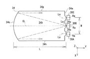
- FIG. 6 is a diagram showing shape parameters of the light guide panel.
- the parameter ⁇ is a value with respect to the orthogonal direction (Y-axis direction) of the facing direction (Z-axis direction) of the display panel 32 and the light guide panel 34, that is, the orthogonal direction of the incident surface 34a. This is the inclination angle of the second reflecting surface 34d.
- the parameter ⁇ is the direction in which the display panel 32 and the light guide panel 34 face each other (Z-axis direction), that is, the tilt angle of the first reflecting surface 34c with respect to the incident surface 34a.
- the critical angle ⁇ 2 can be expressed by the following mathematical formula 2.
- Equation 2 the parameter n is the refractive index of the light guide panel 34.
- the incident angle ⁇ 1 needs to be an angle at which total reflection occurs. That is, it is necessary to satisfy the condition shown in the following Expression 3.
- Equation 4 is a relational expression between the tilt angle ⁇ of the first reflecting surface 34c and the critical angle ⁇ 2 .
- Equation 5 is a condition under which light is emitted from the emission surface 34b without reaching the incidence surface 34a.
- the parameter N is the number of reflections of light after being reflected by the first reflection surface 34c and before being emitted from the light guide panel 34.
- the parameter d is a distance in the direction (Y-axis direction) orthogonal to the facing direction (Z-axis direction) of the display panel 32 and the light guide panel 34, in which the light is reflected once and propagates until the next reflection. The propagation distance in the Y-axis direction per rotation).
- the parameter L 1 is the length of the light guide panel in the direction (Y axis direction) orthogonal to the facing direction (Z axis direction) of the display panel 32 and the light guide panel 34.
- the number of reflections N can be calculated using the following formula 6.
- the second reflecting surface 34d is provided with a plurality of prisms 34f. Considering this prism 34f, when the rising angle of the prism 34f with respect to the second reflection surface 34d is ⁇ p , the formula 6 is replaced by the formula 7.
- the propagation distance d per reflection in Expression 5 can be calculated by Expression 8 below.
- (t 1 +t 2 )/2 in the first term on the right side indicates the average thickness of the entire light guide panel 34 (size in the facing direction (Z-axis direction) of the display panel 32 and the light guide panel 34). ing. Specifically, t 1 is the thickness of the light guide panel 34 at the incident surface 34a, and t 2 is the thickness of the light guide panel 34 at the first reflecting surface 34c.
- Equation 10 which is a condition for passing through the central portion is shown below.
- the parameter N′ is the number of reflections until the incident angle of the light reflected by the first reflecting surface 34c reaches the critical angle ⁇ 2 .
- the parameter d′ is a facing direction (Z-axis direction) of the display panel 32 and the light guide panel 34 in which the light reflected by the first reflecting surface 34c is reflected once and propagates until the next reflection. Is the distance (propagation distance per reflection) in the orthogonal direction (Y-axis direction).
- the parameter L 2 is the Y-axis between the position of the light guide panel 34 corresponding to the center (center point CP) of the display panel 32 in the Y-axis direction and the first reflecting surface 34c. The distance in the direction.
- the number of reflections N′ in Expression 10 is the same as Expression 6 as shown in Expression 11 below.
- the propagation distance d′ for each reflection in Expression 10 can be calculated by Expression 12 below.
- (t 2 +t 3 )/2 of the first term on the right side is the position of the light guide panel 34 corresponding to the center (center point CP) of the display panel 32 in the Y-axis direction and the first reflecting surface 34c.
- the average thickness of the light guide panel 34 (the size of the display panel 32 and the light guide panel 34 in the opposing direction (Z-axis direction)) is shown.
- t 2 is the thickness of the light guide panel 34 at the first reflection surface 34c
- t 3 is the light guide panel corresponding to the center (center point CP) of the display panel 32 in the Y-axis direction.
- the thickness of the light guide panel 34 at the position 34 is shown.
- the product of the number of reflections N′ until the incident angle calculated by Expression 11 becomes the critical angle ⁇ 2 and the propagation distance d′ per reflection calculated by Expression 12 is as shown in Expression 10.
- the light reflected by the first reflecting surface 34c can pass through the central portion of the display panel 32 in the range of 1/2 to 3/2 times the panel length L 2 .
- the light guide panel 34 is obtained. Can emit light from its emission surface 34b so that a large amount of light passes through the central portion of the display panel 32.
- the display device 20 According to the display device 20 according to the first embodiment as described above, it is possible to output a high-luminance image. This will be specifically described.
- FIG. 7 is a diagram showing the positional relationship between the display device according to the first embodiment and the observer's eye box.
- the light (image) output from the display device 20 is guided to the eye box EB of the observer Ob via the reflection optical system RS.
- the eye box EB of the observer Ob riding in the vehicle 10 is a region in which the left-right direction D1 is long and the up-down direction D2 is short.
- the left-right direction and the up-down direction are directions with respect to the observer Ob.
- the left-right direction D1 substantially corresponds to the vehicle width direction of the vehicle 10
- the up-down direction D2 substantially corresponds to the height direction of the vehicle 10.
- the head-up display 14 is mounted on the vehicle 10 so that the lateral direction (X-axis direction) of the display panel 32 of the display device 20 corresponds to the vertical direction D2 of the eye box EB. There is.
- the substantially parallel light is seen in the facing direction (Z-axis direction) of the display panel 32 and the light guide panel 34.
- the light propagating in the light guide panel 34 is emitted from the light guide panel 34 toward the display panel 32 in a state of being substantially parallel light.
- light in a state in which divergence of the display panel 32 in the lateral direction (X-axis direction) is suppressed is output from the display device 20.
- a part of the light is suppressed from passing above and below the eye box EB of the observer Ob, and the amount of light reaching the eye box EB is increased.
- the amount of light output from the display device increases, and the brightness of the image displayed on the windshield 12 increases.
- the head-up display 14 is arranged with respect to the eye box EB so that the vertical direction D2 of the eye box EB of the observer Ob corresponds to the lateral direction (X axis direction) of the display panel 32.
- the light guide panel 34 is manufactured so as to satisfy the following inequalities, for example.
- S(d2) is the size of the eye box EB in the vertical direction D2.
- L is the length of the light guide panel 34 in the longitudinal direction (Y-axis direction) of the display panel 32, and W is between the outermost light sources 30A and 30C. It is a distance.
- a display device mounted on a head-up display of a vehicle can output a high-luminance image.
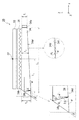
- FIG. 8 is a perspective view of a light guide panel in the display device according to the second embodiment of the present disclosure.
- FIG. 9 is a top view of the light guide panel showing an incident surface of the light guide panel according to the second embodiment.
- the light guide panel 134 of the display device includes a plurality of cylindrical lenses 134e on the incident surface 134a thereof, as in the above-described first embodiment.
- a pair of prisms 134j arranged so as to sandwich the cylindrical lens 134e is provided for each cylindrical lens 134e.
- Each prism 134j includes a light-trapping surface 134k and a reflecting surface 134l.
- Light emitted from the light sources 30A to 30D at an angle that cannot enter the cylindrical lens 134e is taken into the light guide panel 134 via the light taking-in surface 134k of the prism 134j, and is reflected by the reflecting surface 134l in the longitudinal direction of the display panel 32 (Y Reflected in the axial direction). Thereby, most of the light emitted from the plurality of light sources 30A to 30D is taken into the light guide panel 134. As a result, the display device can output an image with higher brightness.
- the display device, the head-up display including the display device, and the vehicle including the head-up display according to the present disclosure have been described above with reference to the above-described embodiments, the embodiments of the present disclosure are not limited thereto. ..
- the incident surface 34a of the light guide panel 34 is provided with a plurality of cylindrical lenses 34e corresponding to the plurality of light sources 30A to 30C.
- the embodiment of the present disclosure is not limited to this.
- the prism sheet that changes the traveling direction of the light so that the light emitted from the emission surface 34b of the light guide panel 34 is directed to the display panel 32.
- An optical member 36 such as is disposed between the display panel 32 and the light guide panel 34.
- the embodiment of the present disclosure is not limited to this.
- the second reflecting surface 34d may reflect light toward the emitting surface 34b in a direction close to the normal direction of the display panel 32. Thereby, it is not necessary to dispose the optical member 36 for changing the traveling direction of the light emitted from the light guide panel 34, between the display panel 32 and the light guide panel 34.
- the moving body is the vehicle 10 such as an automobile
- the moving body is not limited to the vehicle 10.
- the moving body may be a vehicle on which a person rides, for example, an airplane or a ship.
- the mobile may be an unmanned aerial vehicle.
- the moving body may vibrate instead of traveling.
- the present disclosure can be applied to a display device. Further, the present disclosure can be applied to a head-up display.
Abstract
L'invention concerne un dispositif d'affichage comprenant : des sources de lumière (30A-30C) pour émettre de la lumière ; un panneau d'affichage (32) pour afficher une image ; et un panneau de guidage de lumière (34) pour guider la lumière émise par les sources de lumière (30A-30C) vers le panneau d'affichage. Le panneau de guidage de lumière (34) comprend une surface d'incidence (34a) faisant face aux sources de lumière (30A-30C), une surface de sortie (34b) faisant face au panneau d'affichage, une première surface de réflexion (34c) faisant face à la surface d'incidence (34a), et une seconde surface de réflexion (34d) faisant face à la surface de sortie (34b). La première surface de réflexion (34c) a une forme concave pour réfléchir la lumière de telle sorte que la lumière réfléchie soit proche de la lumière parallèle lorsqu'elle est vue dans une direction dans laquelle le panneau d'affichage et le panneau de guidage de lumière se font face dans le panneau de guidage de lumière (34), et est inclinée à un angle supérieur à 0 degré par rapport à la surface d'incidence (34a) et coupe la seconde surface de réflexion (34d) à un angle inférieur à 90 degrés.
Priority Applications (3)
| Application Number | Priority Date | Filing Date | Title |
|---|---|---|---|
| JP2021501586A JP7478959B2 (ja) | 2019-02-28 | 2019-12-03 | 表示装置、ヘッドアップディスプレイ、移動体、および導光パネル |
| EP19916775.0A EP3932718A4 (fr) | 2019-02-28 | 2019-12-03 | Dispositif d'affichage, affichage tête haute, corps mobile et panneau de guidage de lumière |
| US17/393,667 US11867902B2 (en) | 2019-02-28 | 2021-08-04 | Display device, head-up display, moving body, and light guide panel |
Applications Claiming Priority (2)
| Application Number | Priority Date | Filing Date | Title |
|---|---|---|---|
| JP2019036254 | 2019-02-28 | ||
| JP2019-036254 | 2019-02-28 |
Related Child Applications (1)
| Application Number | Title | Priority Date | Filing Date |
|---|---|---|---|
| US17/393,667 Continuation US11867902B2 (en) | 2019-02-28 | 2021-08-04 | Display device, head-up display, moving body, and light guide panel |
Publications (1)
| Publication Number | Publication Date |
|---|---|
| WO2020174798A1 true WO2020174798A1 (fr) | 2020-09-03 |
Family
ID=72238914
Family Applications (1)
| Application Number | Title | Priority Date | Filing Date |
|---|---|---|---|
| PCT/JP2019/047204 WO2020174798A1 (fr) | 2019-02-28 | 2019-12-03 | Dispositif d'affichage, affichage tête haute, corps mobile et panneau de guidage de lumière |
Country Status (4)
| Country | Link |
|---|---|
| US (1) | US11867902B2 (fr) |
| EP (1) | EP3932718A4 (fr) |
| JP (1) | JP7478959B2 (fr) |
| WO (1) | WO2020174798A1 (fr) |
Cited By (1)
| Publication number | Priority date | Publication date | Assignee | Title |
|---|---|---|---|---|
| WO2022230370A1 (fr) * | 2021-04-28 | 2022-11-03 | パナソニックIpマネジメント株式会社 | Système optique, système d'éclairage, système d'affichage, et corps mobile |
Citations (8)
| Publication number | Priority date | Publication date | Assignee | Title |
|---|---|---|---|---|
| JPH06324217A (ja) * | 1993-04-19 | 1994-11-25 | Brightview Technol Inc | 多重反射射光システムを有し、マイクロプリズムを用いるバックライティング用アセンブリ |
| JP2006004877A (ja) * | 2004-06-21 | 2006-01-05 | Nippon Leiz Co Ltd | 導光板および平面照明装置 |
| JP2011090832A (ja) * | 2009-10-21 | 2011-05-06 | Mitsubishi Electric Corp | 面状光源、液晶表示装置 |
| US20120106196A1 (en) * | 2010-10-29 | 2012-05-03 | Cho Hyun Jin | Light guide plate and display apparatus including the same |
| JP2013502697A (ja) * | 2009-08-21 | 2013-01-24 | マイクロソフト コーポレーション | 光学くさびによる効率的な光のコリメーション |
| JP2013161791A (ja) * | 2012-02-03 | 2013-08-19 | Ctx Opto Electronics Corp | 光源モジュール |
| WO2017094209A1 (fr) * | 2015-11-30 | 2017-06-08 | パナソニックIpマネジメント株式会社 | Dispositif d'affichage d'image et dispositif d'affichage tête haute équipé d'un dispositif d'affichage d'image |
| JP2018018710A (ja) * | 2016-07-28 | 2018-02-01 | 株式会社 オルタステクノロジー | 光源装置及びそれを備えた表示装置 |
Family Cites Families (4)
| Publication number | Priority date | Publication date | Assignee | Title |
|---|---|---|---|---|
| US8534901B2 (en) * | 2010-09-13 | 2013-09-17 | Teledyne Reynolds, Inc. | Collimating waveguide apparatus and method |
| KR20120088121A (ko) * | 2011-01-31 | 2012-08-08 | 삼성전자주식회사 | 백라이트 어셈블리 및 이를 갖는 표시장치 |
| EP2850359B1 (fr) | 2012-05-18 | 2020-05-06 | RealD Spark, LLC | Conditionnement d'une source pour imagerie par rétroéclairages directionnels |
| US11327358B2 (en) * | 2017-05-08 | 2022-05-10 | Reald Spark, Llc | Optical stack for directional display |
-
2019
- 2019-12-03 JP JP2021501586A patent/JP7478959B2/ja active Active
- 2019-12-03 EP EP19916775.0A patent/EP3932718A4/fr not_active Withdrawn
- 2019-12-03 WO PCT/JP2019/047204 patent/WO2020174798A1/fr unknown
-
2021
- 2021-08-04 US US17/393,667 patent/US11867902B2/en active Active
Patent Citations (8)
| Publication number | Priority date | Publication date | Assignee | Title |
|---|---|---|---|---|
| JPH06324217A (ja) * | 1993-04-19 | 1994-11-25 | Brightview Technol Inc | 多重反射射光システムを有し、マイクロプリズムを用いるバックライティング用アセンブリ |
| JP2006004877A (ja) * | 2004-06-21 | 2006-01-05 | Nippon Leiz Co Ltd | 導光板および平面照明装置 |
| JP2013502697A (ja) * | 2009-08-21 | 2013-01-24 | マイクロソフト コーポレーション | 光学くさびによる効率的な光のコリメーション |
| JP2011090832A (ja) * | 2009-10-21 | 2011-05-06 | Mitsubishi Electric Corp | 面状光源、液晶表示装置 |
| US20120106196A1 (en) * | 2010-10-29 | 2012-05-03 | Cho Hyun Jin | Light guide plate and display apparatus including the same |
| JP2013161791A (ja) * | 2012-02-03 | 2013-08-19 | Ctx Opto Electronics Corp | 光源モジュール |
| WO2017094209A1 (fr) * | 2015-11-30 | 2017-06-08 | パナソニックIpマネジメント株式会社 | Dispositif d'affichage d'image et dispositif d'affichage tête haute équipé d'un dispositif d'affichage d'image |
| JP2018018710A (ja) * | 2016-07-28 | 2018-02-01 | 株式会社 オルタステクノロジー | 光源装置及びそれを備えた表示装置 |
Non-Patent Citations (1)
| Title |
|---|
| See also references of EP3932718A4 * |
Cited By (1)
| Publication number | Priority date | Publication date | Assignee | Title |
|---|---|---|---|---|
| WO2022230370A1 (fr) * | 2021-04-28 | 2022-11-03 | パナソニックIpマネジメント株式会社 | Système optique, système d'éclairage, système d'affichage, et corps mobile |
Also Published As
| Publication number | Publication date |
|---|---|
| EP3932718A4 (fr) | 2022-03-30 |
| JPWO2020174798A1 (ja) | 2021-12-23 |
| US20210364795A1 (en) | 2021-11-25 |
| US11867902B2 (en) | 2024-01-09 |
| JP7478959B2 (ja) | 2024-05-08 |
| EP3932718A1 (fr) | 2022-01-05 |
Similar Documents
| Publication | Publication Date | Title |
|---|---|---|
| JP6589146B2 (ja) | ヘッドアップディスプレイ、およびヘッドアップディスプレイを搭載した移動体 | |
| KR20170030594A (ko) | 도광 장치 및 허상 표시 장치 | |
| JPWO2017094209A1 (ja) | 映像表示装置および映像表示装置を搭載したヘッドアップディスプレイ | |
| US9581888B2 (en) | Projection apparatus | |
| JP2015045808A (ja) | ヘッドアップディスプレイ装置 | |
| US10613265B2 (en) | Display device | |
| KR102215823B1 (ko) | 표시 장치 및 표시 방법 | |
| WO2020174798A1 (fr) | Dispositif d'affichage, affichage tête haute, corps mobile et panneau de guidage de lumière | |
| JP6917571B2 (ja) | 表示装置 | |
| US20230093703A1 (en) | Display device, head-up display, and mobile object | |
| CN115004080A (zh) | 导光体和虚像显示装置 | |
| WO2021246001A1 (fr) | Dispositif d'affichage, affichage tête haute et objet mobile | |
| WO2020241218A1 (fr) | Dispositif de projection et affichage tête haute | |
| WO2018190434A1 (fr) | Écran et dispositif d'affichage d'image | |
| JP7403105B2 (ja) | 映像表示装置および映像表示装置を搭載したヘッドアップディスプレイ、車両 | |
| WO2024034111A1 (fr) | Dispositif source de lumière plane et dispositif d'affichage à cristaux liquides | |
| US11415800B2 (en) | Head-up display | |
| US20230113611A1 (en) | Image generation unit and head-up display | |
| JP7373292B2 (ja) | 光学素子および画像表示装置 | |
| JP2019066813A (ja) | 導光装置および表示装置 | |
| US20220066218A1 (en) | Virtual image display device and optical unit | |
| US20220066220A1 (en) | Virtual image display device and optical unit | |
| JP2023173159A (ja) | ヘッドアップディスプレイ及び表示装置 | |
| WO2019239465A1 (fr) | Dispositif d'affichage d'image | |
| JP2023173158A (ja) | ヘッドアップディスプレイ及び表示装置 |
Legal Events
| Date | Code | Title | Description |
|---|---|---|---|
| 121 | Ep: the epo has been informed by wipo that ep was designated in this application |
Ref document number: 19916775 Country of ref document: EP Kind code of ref document: A1 |
|
| ENP | Entry into the national phase |
Ref document number: 2021501586 Country of ref document: JP Kind code of ref document: A |
|
| NENP | Non-entry into the national phase |
Ref country code: DE |
|
| ENP | Entry into the national phase |
Ref document number: 2019916775 Country of ref document: EP Effective date: 20210928 |