WO2020170591A1 - 変倍光学系、光学機器、及び変倍光学系の製造方法 - Google Patents
変倍光学系、光学機器、及び変倍光学系の製造方法 Download PDFInfo
- Publication number
- WO2020170591A1 WO2020170591A1 PCT/JP2019/050007 JP2019050007W WO2020170591A1 WO 2020170591 A1 WO2020170591 A1 WO 2020170591A1 JP 2019050007 W JP2019050007 W JP 2019050007W WO 2020170591 A1 WO2020170591 A1 WO 2020170591A1
- Authority
- WO
- WIPO (PCT)
- Prior art keywords
- lens
- lens group
- optical system
- variable power
- power optical
- Prior art date
- Legal status (The legal status is an assumption and is not a legal conclusion. Google has not performed a legal analysis and makes no representation as to the accuracy of the status listed.)
- Ceased
Links
Images




Classifications
-
- G—PHYSICS
- G02—OPTICS
- G02B—OPTICAL ELEMENTS, SYSTEMS OR APPARATUS
- G02B15/00—Optical objectives with means for varying the magnification
- G02B15/14—Optical objectives with means for varying the magnification by axial movement of one or more lenses or groups of lenses relative to the image plane for continuously varying the equivalent focal length of the objective
- G02B15/146—Optical objectives with means for varying the magnification by axial movement of one or more lenses or groups of lenses relative to the image plane for continuously varying the equivalent focal length of the objective having more than five groups
- G02B15/1465—Optical objectives with means for varying the magnification by axial movement of one or more lenses or groups of lenses relative to the image plane for continuously varying the equivalent focal length of the objective having more than five groups the first group being negative
-
- G—PHYSICS
- G02—OPTICS
- G02B—OPTICAL ELEMENTS, SYSTEMS OR APPARATUS
- G02B15/00—Optical objectives with means for varying the magnification
- G02B15/14—Optical objectives with means for varying the magnification by axial movement of one or more lenses or groups of lenses relative to the image plane for continuously varying the equivalent focal length of the objective
- G02B15/145—Optical objectives with means for varying the magnification by axial movement of one or more lenses or groups of lenses relative to the image plane for continuously varying the equivalent focal length of the objective having five groups only
- G02B15/1455—Optical objectives with means for varying the magnification by axial movement of one or more lenses or groups of lenses relative to the image plane for continuously varying the equivalent focal length of the objective having five groups only the first group being negative
- G02B15/145523—Optical objectives with means for varying the magnification by axial movement of one or more lenses or groups of lenses relative to the image plane for continuously varying the equivalent focal length of the objective having five groups only the first group being negative arranged -++-+
-
- G—PHYSICS
- G02—OPTICS
- G02B—OPTICAL ELEMENTS, SYSTEMS OR APPARATUS
- G02B15/00—Optical objectives with means for varying the magnification
- G02B15/14—Optical objectives with means for varying the magnification by axial movement of one or more lenses or groups of lenses relative to the image plane for continuously varying the equivalent focal length of the objective
- G02B15/143—Optical objectives with means for varying the magnification by axial movement of one or more lenses or groups of lenses relative to the image plane for continuously varying the equivalent focal length of the objective having three groups only
- G02B15/1435—Optical objectives with means for varying the magnification by axial movement of one or more lenses or groups of lenses relative to the image plane for continuously varying the equivalent focal length of the objective having three groups only the first group being negative
- G02B15/143507—Optical objectives with means for varying the magnification by axial movement of one or more lenses or groups of lenses relative to the image plane for continuously varying the equivalent focal length of the objective having three groups only the first group being negative arranged -++
-
- G—PHYSICS
- G02—OPTICS
- G02B—OPTICAL ELEMENTS, SYSTEMS OR APPARATUS
- G02B15/00—Optical objectives with means for varying the magnification
- G02B15/14—Optical objectives with means for varying the magnification by axial movement of one or more lenses or groups of lenses relative to the image plane for continuously varying the equivalent focal length of the objective
- G02B15/144—Optical objectives with means for varying the magnification by axial movement of one or more lenses or groups of lenses relative to the image plane for continuously varying the equivalent focal length of the objective having four groups only
- G02B15/1445—Optical objectives with means for varying the magnification by axial movement of one or more lenses or groups of lenses relative to the image plane for continuously varying the equivalent focal length of the objective having four groups only the first group being negative
- G02B15/144507—Optical objectives with means for varying the magnification by axial movement of one or more lenses or groups of lenses relative to the image plane for continuously varying the equivalent focal length of the objective having four groups only the first group being negative arranged -++-
-
- G—PHYSICS
- G02—OPTICS
- G02B—OPTICAL ELEMENTS, SYSTEMS OR APPARATUS
- G02B15/00—Optical objectives with means for varying the magnification
- G02B15/14—Optical objectives with means for varying the magnification by axial movement of one or more lenses or groups of lenses relative to the image plane for continuously varying the equivalent focal length of the objective
- G02B15/145—Optical objectives with means for varying the magnification by axial movement of one or more lenses or groups of lenses relative to the image plane for continuously varying the equivalent focal length of the objective having five groups only
- G02B15/1455—Optical objectives with means for varying the magnification by axial movement of one or more lenses or groups of lenses relative to the image plane for continuously varying the equivalent focal length of the objective having five groups only the first group being negative
- G02B15/145515—Optical objectives with means for varying the magnification by axial movement of one or more lenses or groups of lenses relative to the image plane for continuously varying the equivalent focal length of the objective having five groups only the first group being negative arranged -+++-
-
- G—PHYSICS
- G02—OPTICS
- G02B—OPTICAL ELEMENTS, SYSTEMS OR APPARATUS
- G02B27/00—Optical systems or apparatus not provided for by any of the groups G02B1/00 - G02B26/00, G02B30/00
- G02B27/0012—Optical design, e.g. procedures, algorithms, optimisation routines
-
- G—PHYSICS
- G02—OPTICS
- G02B—OPTICAL ELEMENTS, SYSTEMS OR APPARATUS
- G02B3/00—Simple or compound lenses
- G02B3/02—Simple or compound lenses with non-spherical faces
- G02B3/04—Simple or compound lenses with non-spherical faces with continuous faces that are rotationally symmetrical but deviate from a true sphere, e.g. so called "aspheric" lenses
Definitions
- the present invention relates to a variable power optical system, an optical device, and a method for manufacturing the variable power optical system.
- a variable power optical system includes a first lens group having a negative refractive power, and a rear group having at least one lens group disposed on the image side of the first lens group.
- the distance between adjacent lens groups changes, and the condition of the following equation is satisfied. -4.00 ⁇ (L1r2+L1r1)/(L1r2-L1r1) ⁇ -0.50 100.00° ⁇ 2 ⁇ w
- L1r1 radius of curvature of object-side lens surface of most object-side lens of first lens group
- L1r2 radius of curvature of image-side lens surface of most object-side lens of first lens group 2 ⁇ w: wide angle of variable power optical system Full angle of view in edge state
- a method of manufacturing a variable power optical system according to a first aspect of the present invention is directed to a rear group including a first lens group having negative refractive power and at least one lens group arranged on the image side of the first lens group.
- the distance between adjacent lens groups changes during zooming, and the lens units are arranged so as to satisfy the following condition.
- L1r1 radius of curvature of object-side lens surface of most object-side lens of first lens group
- L1r2 radius of curvature of image-side lens surface of most object-side lens of first lens group 2 ⁇ w: wide angle of variable power optical system Full angle of view in edge state
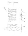
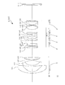
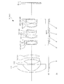
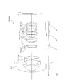
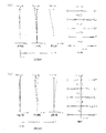
- FIG. 3 is a cross-sectional view showing a lens configuration of a variable power optical system according to the first example.
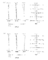
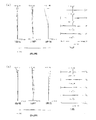
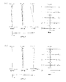
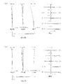
- FIG. 4 is a diagram of various types of aberration of the variable power optical system according to Example 1 upon focusing on an object at infinity, in which (a) shows a wide-angle end state and (b) shows a telephoto end state. It is sectional drawing which shows the lens structure of the variable power optical system which concerns on 2nd Example.
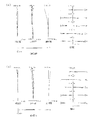
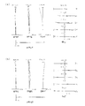
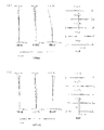
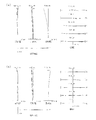
- FIG. 9A is a diagram of various types of aberration of the variable power optical system of the second example when an object at infinity is in focus; FIG. 7A illustrates a wide-angle end state, and FIG. It is sectional drawing which shows the lens structure of the variable power optical system which concerns on 3rd Example.
- FIG. 9A is a diagram of various types of aberration of the variable power optical system of the second example when an object at infinity is in focus
- FIG. 7A illustrates a wide-angle end state
- FIG. It is sectional drawing which shows the lens structure
- FIG. 16A is a diagram of various types of aberration of the variable power optical system according to the third example when focusing on an object at infinity;
- FIG. 11A shows the wide-angle end state, and
- FIG. It is sectional drawing which shows the lens structure of the variable power optical system which concerns on 4th Example.
- FIG. 16A is a diagram of various types of aberration of the variable power optical system of the fourth example when an object at infinity is in focus;
- FIG. 13A shows a wide-angle end state, and FIG. It is sectional drawing which shows the lens structure of the variable power optical system which concerns on 5th Example.
- 19A and 19B are graphs showing various aberrations of the variable power optical system according to Example 5 upon focusing on an object at infinity, wherein FIG.
- FIG. 11A shows a wide-angle end state
- FIG. It is sectional drawing which shows the lens structure of the variable power optical system which concerns on 6th Example.
- 21A and 21B are graphs showing various aberrations of the variable power optical system of Example 6 upon focusing on an object at infinity, wherein FIG. 11A shows a wide-angle end state, and FIG. 9B shows a telephoto end state.
- 19A and 19B are graphs showing various aberrations of the variable power optical system of Example 7 upon focusing on an object at infinity, wherein FIG. 11A shows a wide-angle end state, and FIG. 9B shows a telephoto end state.
- FIG. 19A is a diagram of various types of aberration of the variable power optical system according to the eighth example upon focusing on an object at infinity;
- FIG. 13A shows a wide-angle end state, and
- FIG. It is sectional drawing which shows the lens structure of the variable power optical system which concerns on 9th Example.
- FIG. 16A is a diagram of various types of aberration of the variable power optical system of the ninth example when an object at infinity is in focus;
- FIG. 13A illustrates a wide-angle end state, and
- FIG. 20A and 20B are graphs showing various aberrations of the variable power optical system of the tenth example upon focusing on an object at infinity, wherein FIG. 11A shows a wide-angle end state, and FIG. A sectional view of a camera equipped with the variable power optical system is shown. 9 is a flowchart for explaining a method of manufacturing the variable power optical system.
- the variable power optical system ZL according to the first embodiment includes a first lens group G1 having negative refractive power and having at least two lenses, and a first lens group G1.
- the rear lens group GR has at least one lens unit disposed on the image side. Further, in the variable power optical system ZL according to the first embodiment, adjacent lens groups change during variable power. With this configuration, it is possible to secure a zoom ratio that satisfies the present embodiment.
- variable power optical system ZL according to the first embodiment satisfies the following conditional expression (1).
- ⁇ 1n Abbe number of at least one medium of the negative lenses included in the first lens group G1 with respect to the d-line
- Conditional expression (1) defines the Abbe number of at least one medium of the negative lens included in the first lens group G1 with respect to the d-line (hereinafter, conditional expression (1) of the first lens group G1 is A negative lens that satisfies is called a "specific negative lens").
- conditional expression (1) of the first lens group G1 is A negative lens that satisfies is called a "specific negative lens”).
- the medium (glass material) of the lenses forming the first lens group G1 can be appropriately selected.
- the lower limit of conditional expression (1) is set to 82.00, 85.00, 88.00, 90.00, 93.00, and 95 It is more desirable to set it to 0.00.
- variable power optical system ZL according to the first embodiment satisfy the following conditional expression (2).
- nL1 Refractive index of the medium of the lens closest to the object in the first lens group G1 to the d-line
- nL2 Refractive index of the medium of the second lens from the object side in the first lens group G1 to the d-line
- the conditional expression (2) defines the ratio of the refractive index to the d-line of each medium of the lens closest to the object side and the lens second from the object side in the first lens group G1.
- variable power optical system ZL according to the first embodiment satisfies the following conditional expression (3).
- N1n the number of negative lenses included in the first lens group G1
- Conditional expression (3) defines the number of negative lenses included in the first lens group G1. By satisfying this conditional expression (3), it is possible to reduce the weight by reducing the number of negative lenses in the first lens group G1. In addition, it is possible to reduce aberration fluctuations during focusing and zooming. In order to secure the effect of conditional expression (3), it is desirable to set the upper limit of conditional expression (3) to 3. Further, in order to secure the effect of the conditional expression (3), the lower limit value of the conditional expression (3) is set to 1 (1 ⁇ N1n), that is, the first lens group G1 includes at least one lens. It is desirable to have a negative lens.
- variable power optical system ZL according to the first embodiment satisfies the following conditional expression (4).
- Conditional expression (4) defines the total angle of view of the variable power optical system ZL in the wide-angle end state.
- the variable magnification optical system ZL can be a bright super wide-angle zoom lens.
- the lower limit of conditional expression (4) is set to 105.00°, 110.00°, 112.00°, and further 114.00°. Is more desirable.
- variable power optical system ZL satisfies the following conditional expression (5).
- nL1 Refractive index of the medium of the lens closest to the object in the first lens group G1 to the d-line
- the conditional expression (5) defines the refractive index for the d-line of the medium of the lens closest to the object in the first lens group G1.
- the conditional expression (5) since the lens of the medium (glass material) having the low refractive index is arranged on the most object side of the first lens group G1, the Petzval sum can be corrected well. In addition, it is possible to reduce aberration fluctuations during focusing and zooming.
- the upper limit of conditional expression (5) is set to 1.69, 1.68, 1.66, 1.65, 1.64, and 1 It is more desirable to set it to 0.63.
- the variable power optical system ZL according to the second embodiment includes a first lens group G1 having a negative refractive power, and at least one image side of the first lens group G1.
- the rear lens group GR has a lens group. Further, in the variable power optical system ZL according to the second embodiment, the distance between adjacent lens groups changes during variable power. With this configuration, it is possible to secure a zoom ratio that satisfies the present embodiment.
- variable power optical system ZL according to the second embodiment satisfies the following conditional expression (6).
- fw Focal length of the variable power optical system ZL in the wide-angle end state
- f1 Focal length of the first lens group G1
- Fnow Open F number when focusing on an object at infinity in the wide-angle end state of the variable power optical system ZL
- Conditional expression (6) defines an appropriate refractive power of the first lens group G1 with respect to the open F number of the variable power optical system ZL.
- this conditional expression (6) it is possible to achieve both weight reduction by reducing the number of lenses of the first lens group G1 and high performance due to an appropriate refractive power of the first lens group G1. it can.
- the variable magnification optical system ZL can be applied to a bright super wide-angle zoom lens.
- the upper limit value of the conditional expression (6) is 160.00 mm 2 , 155.00 mm 2 , 150.00 mm 2 , 145.00 mm 2 , 140.
- the lower limit value of the conditional expression (6) is set to 90.00 mm 2 , 95.00 mm 2 , 100.00 mm 2 , 102.00 mm 2 , 103. 300 mm 2, further more preferably set to 104.00mm 2.
- variable power optical system ZL according to the second embodiment satisfies the following conditional expression (3A).
- N1n the number of negative lenses included in the first lens group G1
- conditional expression (3A) is the same as the above-mentioned conditional expression (3).
- variable power optical system ZL according to the second embodiment satisfies the following conditional expression (4).
- variable power optical system ZL according to the second embodiment satisfies the following conditional expression (5).
- nL1 Refractive index of the medium of the lens closest to the object in the first lens group G1 to the d-line
- the variable power optical system ZL according to the third embodiment includes a first lens group G1 having a negative refractive power and at least one of the first lens group G1 arranged on the image side.
- the rear lens group GR has a lens group.
- the distance between adjacent lens groups changes during zooming. With this configuration, it is possible to secure a zoom ratio that satisfies the present embodiment.
- variable power optical system ZL according to the third embodiment satisfies the following conditional expression (7).
- L1r1 radius of curvature of the object-side lens surface of the most object-side lens of the first lens group G1
- L1r2 radius of curvature of the image-side lens surface of the most object-side lens of the first lens group G1
- the conditional expression (7) defines the shape of the lens closest to the object in the first lens group G1.
- the most object-side lens of the first lens group G1 becomes a negative meniscus lens having a convex surface facing the object side, and therefore both miniaturization and good aberration correction are achieved.
- the variable magnification optical system ZL can be applied to a bright super wide-angle zoom lens. If the upper limit of conditional expression (7) is exceeded, distortion will increase and manufacturability will decrease, such being undesirable.
- conditional expression (7) In order to ensure the effect of conditional expression (7), the upper limit of conditional expression (7) is set to -0.60, -0.70, -0.80, -0.85, -0. It is more desirable to set it to 0.90, -0.95, -0.98, -1.00, and further -1.05. On the other hand, if the lower limit of conditional expression (7) is not reached, the radius of curvature of the lens surface on the object side becomes short and the variable-magnification optical system ZL becomes heavy, which is not preferable. In order to ensure the effect of conditional expression (7), the lower limit of conditional expression (7) is set to -3.50, -3.00, -2.50, -2.25, -2. It is more preferable to set it to 0.000, ⁇ 1.80, ⁇ 1.65, and further ⁇ 1.55.
- variable power optical system ZL according to the third embodiment satisfies the following conditional expression (4).
- variable power optical system ZL according to the third embodiment satisfies the following conditional expression (3).
- N1n the number of negative lenses included in the first lens group G1
- variable power optical system ZL according to the third embodiment satisfies the following conditional expression (5).
- nL1 Refractive index of the medium of the lens closest to the object in the first lens group G1 to the d-line
- the variable power optical system ZL according to the fourth embodiment includes a first lens group G1 having a negative refractive power, a second lens group G2 having a positive refractive power, and a positive refractive power. And a third lens group G3 having power.
- the distance between adjacent lens groups changes during zooming, and the first lens group changes during zooming from the wide-angle end state to the telephoto end state. It is desirable that the distance between G1 and the second lens group G2 be reduced. With this configuration, it is possible to secure a zoom ratio that satisfies the present embodiment.
- the second lens group G2 moves to the image side when focusing from an object at infinity to a near object. With this configuration, it is possible to reduce variation in aberration when focusing.
- variable power optical system ZL it is desirable that the first lens group G1 has a negative meniscus lens having a convex surface facing the object side, closest to the object side. With this configuration, it is possible to achieve both miniaturization and excellent aberration correction. In addition, it is possible to reduce aberration fluctuations during focusing and zooming. In addition, the variable magnification optical system ZL can be applied to a bright super wide-angle zoom lens.
- variable power optical system ZL according to the second embodiment satisfies the following conditional expression (3A).
- N1n the number of negative lenses included in the first lens group G1
- conditional expression (3A) is the same as the above-mentioned conditional expression (3).
- variable power optical system ZL according to the second embodiment satisfies the following conditional expression (4).
- the variable power optical system ZL according to the fifth embodiment has a first lens group G1 having a negative refractive power, a second lens group G2 having a positive refractive power, and a positive refractive power. And a third lens group G3 having power.
- the distance between adjacent lens groups changes during zooming, and the first lens group changes during zooming from the wide-angle end state to the telephoto end state. It is desirable that the distance between G1 and the second lens group G2 be reduced. With this configuration, it is possible to secure a zoom ratio that satisfies the present embodiment.
- the second lens group G2 moves to the image side when focusing from an object at infinity to a near object. With this configuration, it is possible to reduce variation in aberration when focusing.
- variable power optical system ZL it is desirable that the first lens group G1 has a negative meniscus lens having a convex surface directed toward the object side on the most object side. With this configuration, it is possible to achieve both miniaturization and excellent aberration correction. In addition, it is possible to reduce aberration fluctuations during focusing and zooming. In addition, the variable magnification optical system ZL can be applied to a bright super wide-angle zoom lens.
- variable power optical system ZL according to the fifth embodiment satisfies the following conditional expression (5).
- nL1 Refractive index of the medium of the lens closest to the object in the first lens group G1 to the d-line
- the variable power optical system ZL according to the sixth embodiment includes a first lens group G1 having a negative refracting power, a second lens group G2 having a positive refracting power, and a positive refracting power. And a third lens group G3 having power.
- the distance between the adjacent lens groups changes during zooming, and the first lens group changes during zooming from the wide-angle end state to the telephoto end state. It is desirable that the distance between G1 and the second lens group G2 be reduced. With this configuration, it is possible to secure a zoom ratio that satisfies the present embodiment.
- the second lens group G2 moves to the image side when focusing from an object at infinity to a near object. With this configuration, it is possible to reduce variation in aberration when focusing.
- variable power optical system ZL it is desirable that the first lens group G1 has a negative meniscus lens having a convex surface facing the object side, closest to the object side. With this configuration, it is possible to achieve both miniaturization and excellent aberration correction. In addition, it is possible to reduce aberration fluctuations during focusing and zooming. In addition, the variable magnification optical system ZL can be applied to a bright super wide-angle zoom lens.
- variable power optical system ZL according to the sixth embodiment satisfies the following conditional expression (8).
- N1n number of negative lenses included in the first lens group G1
- ⁇ 1n total Abbe number for the d-line of the medium of the negative lenses included in the first lens group G1
- Conditional expression (8) defines the ratio of the total Abbe number to the number of negative lenses included in the first lens group G1.
- the medium (glass material) of this lens is selected from those having a low dispersion, so that the chromatic aberration in the entire zoom range is increased. It can be corrected well.
- the lower limit of conditional expression (8) is set to 60.00, 60.50, 61.00, 61.50, 61.80, and 62. It is more desirable to set it to 0.00.
- variable power optical system ZL according to the sixth embodiment satisfy the following conditional expression (9).
- N1n Number of negative lenses included in the first lens group G1 f1: Focal length of the first lens group G1 ⁇ ( ⁇ 1n ⁇ f1n): Abbe number ⁇ 1n with respect to d line of the medium of the negative lens included in the first lens group G1 And sum of products of focal length f1n
- the conditional expression (9) defines an appropriate relationship between the focal length of the first lens group G1 and the ratio of the total Abbe number to the number of negative lenses included in the first lens group G1.
- This conditional expression (9) it is possible to obtain an appropriate refractive power of the first lens group G1 while reducing the number of lenses in the first lens group G1 to make it compact and lightweight.
- the lower limit of conditional expression (9) is set to 105.00, 110.00, 115.00, 118.00, 120.00, 123. 00, and more preferably 125.00.
- variable power optical systems ZL according to the first to sixth embodiments satisfy the following conditional expression (10).
- Conditional expression (10) defines the ratio of the back focus to the focal length of the entire system in the wide-angle end state. By satisfying the conditional expression (10), both miniaturization and excellent aberration correction can be achieved. When the value exceeds the upper limit of conditional expression (10), the back focus becomes too long, which makes it difficult to downsize the variable magnification optical system ZL, which is not preferable.
- the upper limit values of conditional expression (10) are set to 3.50, 3.30, 3.00, 2.90, 2.80, 2. It is more preferable to set it to 75, and further to 2.72.
- conditional expression (10) when the value goes below the lower limit of conditional expression (10), the distance from the image plane to the exit pupil becomes too short, which is unfavorable for aberration correction and securing peripheral light amount.
- the lower limit values of conditional expression (10) are set to 1.25, 1.30, 1.35, 1.40, 1.45, 1. 50, 1.55, and more preferably 1.60 are more desirable.
- variable power optical systems ZL according to the first to sixth embodiments satisfy the following conditional expression (11).
- TLw Total optical length of variable-magnification optical system ZL in wide-angle end state
- STLw Distance on optical axis from lens surface closest to object side in wide-angle end state of variable-magnification optical system ZL
- Conditional expression (11) defines the ratio of the total length to the diaphragm position in the wide-angle end state. By satisfying this conditional expression (11), both miniaturization and excellent aberration correction can be achieved. If the upper limit of conditional expression (11) is exceeded, the distance from the lens surface closest to the object side to the entrance pupil becomes large, and it becomes difficult to correct distortion and field curvature, which is not preferable. In order to ensure the effect of conditional expression (11), the upper limit values of conditional expression (11) are set to 0.68, 0.65, 0.64, 0.63, 0.62, 0. 61, and more preferably 0.58.
- conditional expression (11) is set to 0.43, 0.45, 0.46, 0.47, 0.48, and 0. It is more desirable to set it to 0.49.
- variable power optical systems ZL according to the first to sixth embodiments satisfy the following conditional expression (12).
- fw focal length of the variable-magnification optical system ZL in the wide-angle end state
- f1 focal length of the first lens group G1
- Conditional expression (12) defines the ratio of the focal length of the first lens group G1 to the focal length of the entire system in the wide-angle end state. By satisfying this conditional expression (12), it is possible to determine the refracting power (power) of the first lens group G1 for achieving both miniaturization and high performance. If the upper limit of conditional expression (12) is exceeded, the refractive power of the first lens group G1 becomes too weak and the lens becomes large, which is not preferable. In order to ensure the effect of conditional expression (12), the upper limit values of conditional expression (12) are set to 1.90, 1.80, 1.70, 1.65, 1.63, 1. 60, and more preferably 1.59.
- conditional expression (12) If the lower limit of conditional expression (12) is not reached, the refracting power of the first lens group G1 becomes too strong, and good aberration correction cannot be performed, which is not preferable.
- the lower limit values of conditional expression (12) are set to 1.10, 1.20, 1.25, 1.30, 1.35, 1. 38, 1.40, and more preferably 1.42.
- variable power optical systems ZL according to the first to sixth embodiments satisfy the following conditional expression (13).
- ft focal length of the variable magnification optical system ZL in the telephoto end state
- f1 focal length of the first lens group G1
- Conditional expression (13) defines the ratio of the focal length of the first lens group G1 to the focal length of the entire system in the telephoto end state. By satisfying the conditional expression (13), it is possible to determine the refracting power (power) of the first lens group G1 for achieving both miniaturization and high performance. If the upper limit of conditional expression (13) is exceeded, the refractive power of the first lens group G1 becomes too weak and the lens becomes large, which is not preferable. In order to secure the effect of conditional expression (13), the upper limit of conditional expression (13) is set to 1.15, 1.10, 1.08, 1.05, 1.03, and 1 It is more desirable to set it to 0.00.
- the lower limit of conditional expression (13) is set to 0.70, 0.75, 0.78, 0.80, 0.83, 0. It is more preferable to set it to 85, further to 0.87.
- variable power optical systems ZL according to the first to sixth embodiments satisfy the following conditional expression (14).
- f1 focal length of the first lens group G1
- fL1 focal length of the most object-side lens of the first lens group G1
- the conditional expression (14) defines the ratio of the focal lengths of the first lens group G1 and the lens closest to the object side of the first lens group G1. By satisfying this conditional expression (14), both miniaturization and excellent aberration correction can be achieved. If the upper limit of conditional expression (14) is exceeded, the refractive power (power) of the most object-side lens of the first lens group G1 becomes too weak, which leads to an increase in the size of the variable power optical system ZL and a reduction in the amount of peripheral light. Not preferable. In order to secure the effect of conditional expression (14), the upper limit values of conditional expression (14) are set to 1.90, 1.80, 1.75, 1.70, 1.65, 1. 60, and more preferably 1.59.
- conditional expression (14) If the lower limit of conditional expression (14) is not reached, the refracting power (power) of the most object-side lens of the first lens group G1 becomes too strong, and it becomes difficult to correct coma and field curvature. Absent.
- the lower limit values of conditional expression (14) are set to 1.05, 1.10, 1.15, 1.20, 1.25, 1. 28, and more preferably 1.30.
- variable power optical systems ZL according to the first to sixth embodiments satisfy the following conditional expression (15).
- f1 focal length of the first lens group G1
- fL2 focal length of the second lens from the object side of the first lens group G1
- Conditional expression (15) defines the ratio of the focal lengths of the first lens group G1 and the second lens from the object side of the first lens group G1. By satisfying this conditional expression (15), both miniaturization and excellent aberration correction can be achieved. If the upper limit of conditional expression (15) is exceeded, the refractive power (power) of the second lens from the object side of the first lens group G1 becomes too weak, which is not suitable for correction of field curvature and the like, which is not preferable. In order to ensure the effect of conditional expression (15), the upper limit of conditional expression (15) is set to 3.85, 3.60, 3.50, 3.45, 3.40, 3.40. 35, and more preferably 3.30.
- conditional expression (15) If the lower limit of conditional expression (15) is not reached, the refracting power (power) of the second lens from the object side in the first lens group G1 becomes too strong, and it becomes difficult to correct spherical aberration and coma. Not preferable.
- the lower limit values of conditional expression (15) are set to 1.10, 1.20, 1.50, 1.70, 1.80, 1. 90, 2.00, and more preferably 2.10.
- variable power optical systems ZL according to the first to sixth embodiments satisfy the following conditional expression (16).
- Conditional expression (16) defines the ratio between the back focus and the total length in the wide-angle end state. By satisfying the conditional expression (16), both miniaturization and excellent aberration correction can be achieved.
- the upper limit of conditional expression (16) is set to 7.80, 7.50, 7.25, 7.00, 6.90, 6. 80, 6.75, 6.70, 6.65, and more preferably 6.50.
- the lower limit values of conditional expression (16) are set to 3.65, 3.75, 3.80, 3.85, 3.90, 3. 95, and more preferably 4.00.
- variable power optical system ZL it is desirable that the first lens group G1 has a negative meniscus lens having a convex surface facing the object side, closest to the object side. With this configuration, it is possible to achieve both miniaturization and excellent aberration correction. In addition, it is possible to reduce aberration fluctuations during focusing and zooming. In addition, the variable magnification optical system ZL can be applied to a bright super wide-angle zoom lens.
- variable power optical system ZL satisfies the following conditional expression (7).
- L1r1 radius of curvature of the object-side lens surface of the most object-side lens of the first lens group G1
- L1r2 radius of curvature of the image-side lens surface of the most object-side lens of the first lens group G1
- the first lens group G1 has at least two lenses, and it is desirable that the following conditional expression (17) is satisfied. ..
- L2r1 radius of curvature of the lens surface on the object side of the second lens from the object side of the first lens group G1
- L2r2 radius of curvature of the image surface of the lens on the second side from the object side of the first lens group G1
- Conditional expression (17) defines the shape of the second lens from the object side in the first lens group G1.
- the second lens from the object side of the first lens group G1 becomes a negative meniscus lens having a convex surface facing the object side, and therefore aberration correction can be favorably performed. ..
- the upper limit of conditional expression (17) is set to -0.60, -0.70, -0.75, -0.80, -0. It is more preferable to set it to 0.85, -0.90, -0.95, -1.00, and further -1.05.
- the lower limit value of the conditional expression (17) is set to ⁇ 3.90, ⁇ 3.80, ⁇ 3.70, ⁇ 3.60, ⁇ 3. It is more preferable to set to .50, ⁇ 3.40, ⁇ 3.30, and further ⁇ 3.25.
- the first lens group G1 has at least three lenses, and it is desirable that the following conditional expression (18) is satisfied. ..
- L3r1 radius of curvature of the lens surface on the object side of the third lens from the object side of the first lens group G1
- L3r2 radius of curvature of the lens surface on the image side of the third lens from the object side of the first lens group G1
- the conditional expression (18) defines the shape of the third lens from the object side in the first lens group G1.
- the third lens from the object side of the first lens group G1 becomes a biconcave negative lens, and therefore aberration correction can be satisfactorily performed.
- the upper limit of conditional expression (18) is exceeded, it becomes difficult to correct coma aberration, which is not preferable.
- the upper limit of conditional expression (18) is set to 0.70, 0.60, 0.50, 0.45, 0.40, 0. 35, 0.30, and more preferably 0.28. If the lower limit of conditional expression (18) is not reached, it becomes difficult to correct coma aberration, which is not preferable.
- conditional expression (18) In order to secure the effect of conditional expression (18), the lower limit of conditional expression (18) is set to -0.70, -0.60, -0.50, -0.45, -0. It is more preferable that the value is set to 0.40, -0.35, -0.30, and further -0.28.
- variable power optical system ZL it is desirable that the first lens group G1 moves in the optical axis direction during variable power. With such a configuration, it is possible to reduce aberration fluctuation during zooming.
- the first lens group G1 be composed of a negative lens, a negative lens, a negative lens, and a positive lens in order from the object side. .. With this configuration, it is possible to excellently correct various aberrations, particularly distortion and field curvature.
- each of these negative lens, negative lens, negative lens, and positive lens may be arranged as a single lens, or any of adjacent lenses may be arranged as a cemented lens. Good.
- variable power optical system ZL it is desirable that a part of the rear group GR moves to the image side when focusing from an object at infinity to a near object. With this configuration, it is possible to reduce variation in aberration when focusing.
- the rear lens group GR has a second lens group G2 having a positive refractive power and a third lens group G3 having a negative refractive power. It is desirable that the second lens group G2 moves to the image side when focusing from an object at infinity to a near object. With this configuration, it is possible to reduce variation in aberration when focusing.
- variable power optical system ZL has at least one lens group on the image side of the third lens group G3.
- variable power optical system ZL it is desirable that the rear lens group GR (or the lens group after the second lens group G2) include one or more aspherical surfaces. With this configuration, it is possible to excellently correct various aberrations, particularly field curvature.
- the rear lens group GR (or the lens group after the second lens group G2) satisfies the following conditional expression (19) (this lens Is referred to as a “specific lens”).
- the conditional expression (19) defines the Abbe number for the d-line of the medium of the specific lens included in the rear lens group GR (or the lens group after the second lens group G2).
- the rear group GR has at least one lens (specific lens) that satisfies the conditional expression (19)
- the lower limit of conditional expression (19) is set to 67.00, 67.50, 68.00, 70.00, 74.00, 78. 00, 80.00, and more preferably 81.00.
- variable power optical systems ZL according to the first to sixth embodiments satisfy the following conditional expression (20).
- Fnow Open F number at the time of focusing an object at infinity in the wide-angle end state of the variable magnification optical system ZL
- conditional expression (20) defines the open F number when the object at infinity is focused in the wide-angle end state of the variable power optical system ZL. By satisfying this conditional expression (20), it is possible to secure a good resolution that satisfies this embodiment in the wide-angle end state.
- the lower limit of conditional expression (20) is set to 4.05, 4.00, 3.80, 3.60, 3.40, 3.40. It is more preferable to set to 0.20, 3.00, and further 2.95.
- variable power optical systems ZL according to the first to sixth embodiments satisfy the following conditional expression (21).
- Fnot Open F number when the object at infinity is focused in the telephoto end state of the variable magnification optical system ZL
- Conditional expression (21) defines the open F number when the object at infinity is focused in the telephoto end state of the variable magnification optical system ZL. By satisfying this conditional expression (21), it is possible to secure a good resolution satisfying the present embodiment in the telephoto end state.
- the lower limit values of the conditional expression (21) are set to 5.50, 5.30, 5.00, 4.80, 4.50, 4 and 4. 0.05, 4.00, 3.80, 3.60, 3.40, 3.20, 3.00, and more preferably 2.95.
- variable power optical system ZL may have a filter on the object side of the first lens group G1. Even if the filter is arranged on the object side of the first lens group G1, the filter does not become large, so that the entire variable magnification optical system ZL can be made compact.
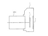
- the camera 1 is a so-called mirrorless camera of an interchangeable lens type, which includes a variable power optical system ZL according to the present embodiment as a taking lens 2.
- a taking lens 2 In the camera 1, light from an object (subject) (not shown) is condensed by the taking lens 2 and is passed through an OLPF (Optical low pass filter) (not shown) on the image pickup surface of the image pickup unit 3.
- OLPF Optical low pass filter
- a subject image is formed on.
- the subject image is photoelectrically converted by the photoelectric conversion element provided in the imaging unit 3 to generate an image of the subject.
- This image is displayed on an EVF (Electronic viewfinder) 4 provided in the camera 1. This allows the photographer to observe the subject through the EVF 4.
- EVF Electronic viewfinder
- variable-magnification optical system ZL according to the present embodiment is applied to a single-lens reflex type camera having a quick return mirror in the camera body and observing an object with a finder optical system. The same effect as that of the camera 1 can be obtained even when the camera is mounted.
- the optical device according to the present embodiment includes the variable power optical system ZL having the above-described configuration, so that the optical device has a small size and a wide angle of view, and excellent aberration variation during zooming and focusing. It is possible to realize a suppressed optical device.
- variable power optical system ZL having a configuration of 2 to 5 groups is shown, but the above configuration conditions and the like can be applied to other group configurations such as 6 and 7 groups. Further, a configuration in which a lens or a lens group is added to the most object side or a configuration in which a lens or a lens group is added to the most image side may be used. Further, the lens group refers to a portion having at least one lens, which is separated by an air gap that changes during zooming.
- a single lens group, a plurality of lens groups, or a partial lens group may be moved in the optical axis direction to form a focusing lens group for focusing from an object at infinity to a near object.
- the focusing lens group can be applied to autofocus and is also suitable for driving a motor for autofocus (such as an ultrasonic motor).
- a motor for autofocus such as an ultrasonic motor
- the image blur caused by camera shake is corrected by moving the lens group or partial lens group so that it has a component in the direction perpendicular to the optical axis, or by rotating (swinging) in the in-plane direction including the optical axis.
- It may be a vibration-proof lens group.
- the lens surface may be formed as a spherical surface, a flat surface, or an aspherical surface.
- the lens surface is a spherical surface or a flat surface, lens processing and assembly adjustment are facilitated, and deterioration of optical performance due to processing and assembly adjustment errors is prevented, which is preferable. Further, even if the image plane is deviated, the drawing performance is less deteriorated, which is preferable.
- the aspherical surface can be an aspherical surface formed by grinding, a glass mold aspherical surface formed by molding glass into an aspherical shape, or a composite type aspherical surface formed by resin forming an aspherical surface on the glass surface. It may be any aspherical surface.
- the lens surface may be a diffractive surface, and the lens may be a gradient index lens (GRIN lens) or a plastic lens.
- GRIN lens gradient index lens
- the aperture stop S is preferably arranged in the rear group GR (for example, in the vicinity of the third lens group G3 (on the image side of the third lens group G3 or in the third lens group G3)), but the aperture stop S
- the role of the lens may be substituted by the frame of the lens without providing the member.
- each lens surface may be coated with an antireflection film having high transmittance in a wide wavelength range.
- variable power optical system ZL of this embodiment has a variable power ratio of about 1.2 to 3.0.
- each lens is arranged to prepare a first lens group G1 having a negative refractive power and a rear lens group GR having at least one lens group (step S100), and these lens groups are arranged (step S200). ..
- the first lens group G1 and the rear group GR are arranged such that the distance between adjacent lens groups changes during zooming.
- the rear lens group GR includes the second lens group G2 having a positive refractive power and the third lens group G3 having a positive refractive power, the distance between the first lens group G1 and the second lens group G2.
- step S300 Is arranged such that the second lens group G2 moves toward the image side when focusing from an infinitely distant object to a short-distance object, and the first lens group G1 is located closest to the object side and the object side.
- a negative meniscus lens with the convex surface facing is arranged. Furthermore, it arranges so that the conditions by the above-mentioned conditional expressions may be satisfied (step S300).
- variable power optical system that is compact and has a wide angle of view and high optical performance
- an optical device having this variable power optical system and a method for manufacturing the variable power optical system.
- FIG. 3 is a cross-sectional view showing the configuration of ZL1 to ZL10) and the distribution of refractive power. Further, in the lower part of the cross-sectional views of these variable power optical systems ZL1 to ZL10, the light of each lens group G1 to G3, G4 or G5 at the time of zooming from the wide-angle end state (W) to the telephoto end state (T) is shown. The direction of movement along the axis is indicated by the arrow.
- the height of the aspherical surface in the direction perpendicular to the optical axis is y, and the distance along the optical axis from the tangent plane of the apex of each aspherical surface to the aspherical surface at the height y (sag amount).
- Is S(y) the radius of curvature of the reference spherical surface (paraxial radius of curvature) is r, the conic constant is K, and the aspherical coefficient of the nth order is An. ..
- En means " x10 -n ".
- the quadratic aspherical surface coefficient A2 is 0. Further, in the tables of each example, the aspherical surface is marked with * on the right side of the surface number.
- FIG. 1 is a diagram showing the configuration of a variable power optical system ZL1 according to the first example.
- the variable power optical system ZL1 includes, in order from the object side, a first lens group G1 having a negative refractive power and a rear group GR having a positive refractive power.
- the rear group GR includes, in order from the object side, a second lens group G2 having a positive refractive power, a third lens group G3 having a positive refractive power, and a fourth lens group G4 having a negative refractive power.
- a fifth lens group G5 having a positive refractive power.
- the first lens group G1 has a negative meniscus lens shape in which a lens surface on the object side and a lens surface on the image side are formed in an aspherical shape in order from the object side, and a convex surface faces the object side.
- Aspherical negative lens L11 a negative meniscus lens-shaped aspherical negative lens L12 having an image-side lens surface formed in an aspherical shape and having a convex surface facing the object side, a biconcave negative lens L13, and a biconvex positive lens L14. It is composed of.
- the second lens group G2 is a cemented lens in which, in order from the object side, a positive meniscus lens L21 having a convex surface facing the object side, and a negative meniscus lens L22 having a convex surface facing the object side and a biconvex positive lens L23 are cemented. It is composed of.
- the third lens group G3 is composed of a cemented lens in which a negative meniscus lens L31 having a convex surface facing the object side and a biconvex positive lens L32 are cemented in order from the object side.
- the fourth lens group G4 is composed of, in order from the object side, a cemented lens in which a biconcave negative lens L41 and a positive meniscus lens L42 having a convex surface facing the object side are cemented, and a biconvex positive lens L43.
- the fifth lens group G5 includes, in order from the object side, a cemented lens in which a biconvex positive lens L51 and a negative meniscus lens L52 having a concave surface facing the object side are cemented, and a negative meniscus lens L53 having a convex surface facing the object side.
- a filter FL is arranged between the fifth lens group G5 and the image plane I.
- the distance between the first lens group G1 and the second lens group G2 decreases during zooming from the wide-angle end state to the telephoto end state, and the second lens group G2 and the third lens group G2 decrease.
- the distance between G3 and G3 increases, the distance between the third lens group G3 and the fourth lens group G4 increases, the distance between the fourth lens group G4 and the fifth lens group G5 decreases, and the fifth lens group G5 and
- the first lens group G1 moves toward the image side so that the interval (back focus) from the image plane I increases, and the second lens group G2, the third lens group G3, the fourth lens group G4, and the fifth lens group G4.
- G5 moves to the object side.
- the aperture stop S is arranged between the third lens group G3 and the fourth lens group G4, and moves together with the fourth lens group G4 during zooming.
- variable-magnification optical system ZL1 is also configured to perform focusing from an object at infinity to a near object by moving the second lens group G2 to the image side.
- Table 1 below lists the values of the specifications of the variable power optical system ZL1.
- f is the focal length of the entire system
- FNO is the F number
- 2 ⁇ is the entire angle of view
- Ymax is the maximum image height
- TL is the total length
- Bf is the back focus.
- the total length TL represents the distance on the optical axis from the first surface of the lens surface to the image plane I when an object at infinity is focused.
- the back focus Bf indicates the distance on the optical axis from the most image-side lens surface (the 32nd surface in FIG. 1) to the image surface I.
- the first column m is the order (surface number) of the lens surfaces from the object side along the traveling direction of the light beam
- the second column r is the radius of curvature of each lens surface
- the third column is d is the distance (surface spacing) on the optical axis from each optical surface to the next optical surface
- the radius of curvature 0.0000 indicates a plane
- the refractive index of air 1.00000 is omitted.
- the lens group focal length indicates the starting surface and the focal length of each of the first to fifth lens groups G1 to G5.
- the unit of the focal length f, the radius of curvature r, the surface distance d, and the other lengths, which are described in all of the following specification values, are generally “mm”, but the optical system is proportionally enlarged or proportional. Even if the size is reduced, the same optical performance can be obtained, and the size is not limited to this. Further, the explanation of these reference numerals and the explanation of the specification table are the same in the following examples.
- the 18th surface indicates the aperture stop S
- the 9th, 24th, and 33rd surfaces indicate virtual surfaces.
- a sub diaphragm can be arranged on the 24th surface.
- variable power optical system ZL1 when placing the filter on the object side of this variable power optical system ZL1, it is placed at a position 6.10 mm away from the first surface on the object side.
- each lens surface of the first surface, the second surface, the fourth surface and the 32nd surface is formed in an aspherical shape.
- Table 2 below shows aspherical surface data for each surface, that is, the values of the conical constant K and the aspherical surface constants A4 to A12.
- variable power optical system ZL1 the axial air distances d8 and d9 between the first lens group G1 and the second lens group G2, the axial air distance d14 between the second lens group G2 and the third lens group G3, the third On-axis air distance d17 between the lens group G3 and the fourth lens group G4, on-axis air distance d24 between the fourth lens group G4 and the fifth lens group G5, and on-axis air between the fifth lens group G5 and the filter FL.
- the air gap d32 changes during zooming and focusing.
- Table 3 shows variable distances at the focal lengths of the wide-angle end state, the intermediate focal length state, and the telephoto end state when focused on an object at infinity, focused on a short-distance object, and focused on the closest object. Indicates a value.
- f indicates the focal length
- ⁇ indicates the magnification
- d0 indicates the distance from the first surface to the object. This description is the same in the following embodiments.
- Table 4 below shows the values corresponding to each conditional expression in the variable power optical system ZL1.
- the specific negative lens is the biconcave negative lens L13, and the specific lenses are the biconvex positive lens L51 and the biconvex positive lens L54.
- variable power optical system ZL1 satisfies all of the above conditional expressions (1) to (21).
- Fig. 2 shows various aberration diagrams of this variable power optical system ZL1 in the wide-angle end state and the telephoto end state when focusing an object at infinity.
- FNO represents an F number
- Y represents an image height.
- the F number value corresponding to the maximum aperture is shown
- the astigmatism diagram and the distortion diagram the maximum image height is shown
- the lateral aberration diagram the image height value is shown.
- variable power optical system ZL1 has excellent imaging performance by satisfactorily correcting various aberrations from the wide-angle end state to the telephoto end state.
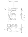
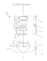
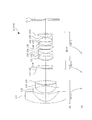
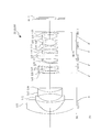
- FIG. 3 is a diagram showing the configuration of the variable power optical system ZL2 according to the second example.
- the variable power optical system ZL2 includes, in order from the object side, a first lens group G1 having a negative refractive power and a rear group GR having a positive refractive power.
- the rear group GR includes, in order from the object side, a second lens group G2 having a positive refractive power, a third lens group G3 having a positive refractive power, and a fourth lens group G4 having a negative refractive power.
- a fifth lens group G5 having a positive refractive power.
- the first lens group G1 has a negative meniscus lens shape in which a lens surface on the object side and a lens surface on the image side are formed in an aspherical shape in order from the object side, and a convex surface faces the object side.
- Aspherical negative lens L11 a negative meniscus lens-shaped aspherical negative lens L12 having an image-side lens surface formed in an aspherical shape and having a convex surface facing the object side, a biconcave negative lens L13, and a biconvex positive lens L14. It is composed of.
- the second lens group G2 is a cemented lens in which, in order from the object side, a positive meniscus lens L21 having a convex surface facing the object side, and a negative meniscus lens L22 having a convex surface facing the object side and a biconvex positive lens L23 are cemented. It is composed of.
- the third lens group G3 is composed of a cemented lens in which a negative meniscus lens L31 having a convex surface facing the object side and a biconvex positive lens L32 are cemented in order from the object side.
- the fourth lens group G4 is composed of, in order from the object side, a cemented lens in which a biconcave negative lens L41 and a biconvex positive lens L42 are cemented, and a biconvex positive lens L43.
- the fifth lens group G5 includes, in order from the object side, a cemented lens in which a biconvex positive lens L51 and a negative meniscus lens L52 having a concave surface facing the object side are cemented, and a negative meniscus lens L53 having a convex surface facing the object side.
- a filter FL is arranged between the fifth lens group G5 and the image plane I.
- the distance between the first lens group G1 and the second lens group G2 decreases during zooming from the wide-angle end state to the telephoto end state, and the second lens group G2 and the third lens group G2 decrease.
- the distance between G3 and G3 changes, the distance between the third lens group G3 and the fourth lens group G4 increases, the distance between the fourth lens group G4 and the fifth lens group G5 decreases, and the fifth lens group G5 changes.
- the first lens group G1 moves toward the image side so that the interval (back focus) from the image plane I increases, and the second lens group G2, the third lens group G3, the fourth lens group G4, and the fifth lens group G4.
- G5 moves to the object side.
- the aperture stop S is arranged between the third lens group G3 and the fourth lens group G4, and moves together with the fourth lens group G4 during zooming.
- variable power optical system ZL2 is configured to focus an object at infinity to a near object by moving the second lens group G2 to the image side.
- Table 5 below shows the values of the specifications of the variable magnification optical system ZL2.
- the 18th surface indicates the aperture stop S
- the 9th, 24th, and 33rd surfaces indicate virtual surfaces.
- a sub diaphragm can be arranged on the 24th surface.
- variable power optical system ZL2 when the filter is placed on the object side of this variable power optical system ZL2, it is placed at a position 6.10 mm away from the first surface to the object side.
- each lens surface of the first surface, the second surface, the fourth surface and the 32nd surface is formed in an aspherical shape.
- Table 6 below shows data of the surface number m and the aspherical surface, that is, the values of the conical constant K and the respective aspherical surface constants A4 to A12.
- variable power optical system ZL2 the axial air distances d8 and d9 between the first lens group G1 and the second lens group G2, the axial air distance d14 between the second lens group G2 and the third lens group G3, the third On-axis air distance d17 between the lens group G3 and the fourth lens group G4, on-axis air distance d24 between the fourth lens group G4 and the fifth lens group G5, and on-axis between the fifth lens group G5 and the filter FL.
- the air gap d32 changes during zooming and focusing.
- Table 7 shows variable distances at various focal lengths in the wide-angle end state, the intermediate focal length state, and the telephoto end state when focused on an object at infinity, focused on a short-distance object, and focused on the closest object. Indicates a value.
- Table 8 below shows the values corresponding to each conditional expression in the variable power optical system ZL2.
- the specific negative lens is the biconcave negative lens L13
- the specific lenses are the biconvex positive lens L51 and the biconvex positive lens L54.
- variable power optical system ZL2 satisfies all of the above conditional expressions (1) to (21).
- Fig. 4 shows various aberration diagrams of this variable power optical system ZL2 in the wide-angle end state and the telephoto end state when focusing an object at infinity. From these various aberration diagrams, it is understood that this variable power optical system ZL2 has excellent imaging performance by satisfactorily correcting various aberrations from the wide-angle end state to the telephoto end state.
- FIG. 5 is a diagram showing the configuration of a variable power optical system ZL3 according to the third example.
- the variable power optical system ZL3 includes, in order from the object side, a first lens group G1 having a negative refractive power and a rear group GR having a positive refractive power.
- the rear group GR includes, in order from the object side, a second lens group G2 having a positive refractive power, a third lens group G3 having a positive refractive power, and a fourth lens group G4 having a negative refractive power.
- a fifth lens group G5 having a positive refractive power.
- the first lens group G1 has a negative meniscus lens shape in which a lens surface on the object side and a lens surface on the image side are formed in an aspherical shape in order from the object side, and a convex surface faces the object side.
- the second lens group G2 includes, in order from the object side, a positive meniscus lens L21 having a convex surface facing the object side, a negative meniscus lens L22 having a convex surface facing the object side, and a positive meniscus lens L23 having a convex surface facing the object side. It is composed of a cemented lens in which and are cemented.
- the third lens group G3 is composed of a cemented lens in which a negative meniscus lens L31 having a convex surface facing the object side and a biconvex positive lens L32 are cemented in order from the object side.
- the fourth lens group G4 is composed of, in order from the object side, a cemented lens in which a biconcave negative lens L41 and a positive meniscus lens L42 having a convex surface facing the object side are cemented, and a biconvex positive lens L43.
- the fifth lens group G5 includes, in order from the object side, a cemented lens in which a biconvex positive lens L51 and a negative meniscus lens L52 having a concave surface facing the object side are cemented, and a negative meniscus lens L53 having a convex surface facing the object side.
- a biconvex positive lens L54 and a lens surface on the image side are formed in an aspherical shape, and are formed by a cemented lens in which a positive meniscus lens-shaped aspherical positive lens L55 having a concave surface facing the object side is cemented.
- a filter FL is arranged between the fifth lens group G5 and the image plane I.
- the distance between the first lens group G1 and the second lens group G2 decreases during zooming from the wide-angle end state to the telephoto end state, and the second lens group G2 and the third lens group
- the distance between G3 and G3 changes, the distance between the third lens group G3 and the fourth lens group G4 increases, the distance between the fourth lens group G4 and the fifth lens group G5 decreases, and the fifth lens group G5 changes.
- the first lens group G1 moves toward the image side so that the interval (back focus) from the image plane I increases, and the second lens group G2, the third lens group G3, the fourth lens group G4, and the fifth lens group G4.
- G5 moves to the object side.
- the aperture stop S is arranged between the third lens group G3 and the fourth lens group G4, and moves together with the third lens group G3 during zooming.
- variable power optical system ZL3 is configured to focus an object at infinity to a near object by moving the second lens group G2 to the image side.
- Table 9 below shows the values of specifications of the variable magnification optical system ZL3.
- the 18th surface indicates the aperture stop S
- the 9th, 24th, and 32nd surfaces indicate virtual surfaces.
- a sub diaphragm can be arranged on the 24th surface.
- variable power optical system ZL3 when the filter is placed on the object side of this variable power optical system ZL3, it is placed 6.10 mm away from the first surface on the object side.
- each lens surface of the first surface, the second surface, the fourth surface and the 31st surface is formed in an aspherical shape.
- Table 10 below shows data of the surface number m and the aspherical surface, that is, the values of the conical constant K and the respective aspherical surface constants A4 to A12.
- variable power optical system ZL3 the axial air distances d8 and d9 between the first lens group G1 and the second lens group G2, the axial air distance d14 between the second lens group G2 and the third lens group G3, and the third On-axis air distance d18 between the lens group G3 and the fourth lens group G4, on-axis air distance d24 between the fourth lens group G4 and the fifth lens group G5, and on-axis between the fifth lens group G5 and the filter FL.
- the air gap d31 changes during zooming and focusing.
- Table 11 shows variable distances at the focal lengths of the wide-angle end state, the intermediate focal length state, and the telephoto end state when focused on an object at infinity, focused on a short-distance object, and focused on the closest object, respectively. Indicates a value.
- Table 12 below shows the values corresponding to each conditional expression in the variable power optical system ZL3.
- the specific negative lens is the biconcave negative lens L13, and the specific lenses are the biconvex positive lens L51 and the biconvex positive lens L54.
- variable power optical system ZL3 satisfies all of the above conditional expressions (1) to (21).
- FIG. 6 shows various aberration diagrams of this variable power optical system ZL3 at the wide-angle end state and the telephoto end state when focusing an object at infinity. From these various aberration diagrams, it is understood that this variable power optical system ZL3 has excellent imaging performance by satisfactorily correcting various aberrations from the wide-angle end state to the telephoto end state.
- FIG. 7 is a diagram showing the configuration of a variable power optical system ZL4 according to the fourth example.
- the variable power optical system ZL4 is composed of, in order from the object side, a first lens group G1 having a negative refractive power and a rear group GR having a positive refractive power.
- the rear group GR includes, in order from the object side, a second lens group G2 having a positive refractive power, a third lens group G3 having a positive refractive power, and a fourth lens group G4 having a negative refractive power.
- a fifth lens group G5 having a positive refractive power.
- the first lens group G1 has a negative meniscus lens shape in which a lens surface on the object side and a lens surface on the image side are formed in an aspherical shape in order from the object side, and a convex surface faces the object side.
- the second lens group G2 is a cemented lens in which, in order from the object side, a positive meniscus lens L21 having a convex surface facing the object side, and a negative meniscus lens L22 having a convex surface facing the object side and a biconvex positive lens L23 are cemented. It is composed of.
- the third lens group G3 is composed of a cemented lens in which a negative meniscus lens L31 having a convex surface facing the object side and a biconvex positive lens L32 are cemented in order from the object side.
- the fourth lens group G4 is composed of, in order from the object side, a cemented lens in which a biconcave negative lens L41 and a biconvex positive lens L42 are cemented, and a positive meniscus lens L43 having a convex surface facing the object side.
- the fifth lens group G5 includes, in order from the object side, a cemented lens in which a biconvex positive lens L51 and a negative meniscus lens L52 having a concave surface facing the object side are cemented, and a negative meniscus lens L53 having a convex surface facing the object side.
- a biconvex positive lens L54 and a lens surface on the image side are formed in an aspherical shape, and are formed by a cemented lens in which a positive meniscus lens-shaped aspherical positive lens L55 having a concave surface facing the object side is cemented.
- a filter FL is arranged between the fifth lens group G5 and the image plane I.
- the distance between the first lens group G1 and the second lens group G2 decreases during zooming from the wide-angle end state to the telephoto end state, and the second lens group G2 and the third lens group G2.
- the distance between G3 and G3 changes, the distance between the third lens group G3 and the fourth lens group G4 increases, the distance between the fourth lens group G4 and the fifth lens group G5 decreases, and the fifth lens group G5 changes.
- the first lens group G1 moves toward the image side so that the interval (back focus) from the image plane I increases, and the second lens group G2, the third lens group G3, the fourth lens group G4, and the fifth lens group G4.
- G5 moves to the object side.
- the aperture stop S is arranged between the third lens group G3 and the fourth lens group G4, and moves together with the third lens group G3 during zooming.
- variable-magnification optical system ZL4 is configured to focus an object at infinity to a near object by moving the second lens group G2 to the image side.
- Table 13 below shows the values of the specifications of the variable power optical system ZL4.
- the 18th surface indicates the aperture stop S
- the 9th, 24th, and 32nd surfaces indicate virtual surfaces.
- a sub diaphragm can be arranged on the 24th surface.
- variable power optical system ZL4 when placing the filter on the object side of this variable power optical system ZL4, it is placed at a position 6.10 mm away from the first surface on the object side.
- each lens surface of the first surface, the second surface, the fourth surface and the 31st surface is formed in an aspherical shape.
- Table 14 below shows data of the surface number m and the aspherical surface, that is, the values of the conical constant K and the respective aspherical surface constants A4 to A12.
- variable power optical system ZL4 the axial air distances d8 and d9 between the first lens group G1 and the second lens group G2, the axial air distance d14 between the second lens group G2 and the third lens group G3, the third On-axis air distance d18 between the lens group G3 and the fourth lens group G4, on-axis air distance d24 between the fourth lens group G4 and the fifth lens group G5, and on-axis between the fifth lens group G5 and the filter FL.
- the air gap d31 changes during zooming and focusing.
- Table 15 shows variable distances at various focal lengths in the wide-angle end state, the intermediate focal length state, and the telephoto end state when focusing on an object at infinity, focusing on a short-distance object, and focusing on the closest object. Indicates a value.
- Table 16 below shows the values corresponding to each conditional expression in the variable magnification optical system ZL4.
- the specific negative lens is the biconcave negative lens L13, and the specific lenses are the biconvex positive lens L51 and the biconvex positive lens L54.
- variable power optical system ZL4 satisfies all of the above conditional expressions (1) to (21).
- Fig. 8 shows various aberration diagrams of this variable power optical system ZL4 in the wide-angle end state and the telephoto end state when focusing an object at infinity. From these various aberration diagrams, it is understood that this variable power optical system ZL4 has excellent imaging performance by satisfactorily correcting various aberrations from the wide-angle end state to the telephoto end state.
- FIG. 9 is a diagram showing the configuration of the variable power optical system ZL5 according to the fifth example.
- the variable power optical system ZL5 is composed of, in order from the object side, a first lens group G1 having a negative refractive power and a rear group GR having a positive refractive power.
- the rear group GR includes, in order from the object side, a second lens group G2 having a positive refractive power, a third lens group G3 having a positive refractive power, and a fourth lens group G4 having a negative refractive power.
- a fifth lens group G5 having a positive refractive power.
- the first lens group G1 has a negative meniscus lens shape in which a lens surface on the object side and a lens surface on the image side are formed in an aspherical shape in order from the object side, and a convex surface faces the object side.
- Aspherical negative lens L11 a negative meniscus lens-shaped aspherical negative lens L12 having an image-side lens surface formed in an aspherical shape and having a convex surface facing the object side, a biconcave negative lens L13, and a biconvex positive lens L14. It is composed of.
- the second lens group G2 is a cemented lens in which, in order from the object side, a positive meniscus lens L21 having a convex surface facing the object side, and a negative meniscus lens L22 having a convex surface facing the object side and a biconvex positive lens L23 are cemented. It is composed of.
- the third lens group G3 is composed of a cemented lens in which a negative meniscus lens L31 having a convex surface facing the object side and a biconvex positive lens L32 are cemented in order from the object side.
- the fourth lens group G4 is composed of, in order from the object side, a cemented lens in which a biconcave negative lens L41 and a biconvex positive lens L42 are cemented, and a positive meniscus lens L43 having a convex surface facing the object side.
- the fifth lens group G5 includes, in order from the object side, a cemented lens in which a biconvex positive lens L51 and a negative meniscus lens L52 having a concave surface facing the object side are cemented, and a plano-concave negative lens having a flat surface facing the object side.
- a filter FL is arranged between the fifth lens group G5 and the image plane I.
- variable power optical system ZL5 the distance between the first lens group G1 and the second lens group G2 decreases during zooming from the wide-angle end state to the telephoto end state, and the second lens group G2 and the third lens group
- the distance between G3 and G3 changes, the distance between the third lens group G3 and the fourth lens group G4 increases, the distance between the fourth lens group G4 and the fifth lens group G5 decreases, and the fifth lens group G5 changes.
- the first lens group G1 moves toward the image side so that the interval (back focus) from the image plane I increases, and the second lens group G2, the third lens group G3, the fourth lens group G4, and the fifth lens group G4.
- G5 moves to the object side.
- the aperture stop S is arranged between the third lens group G3 and the fourth lens group G4, and moves together with the third lens group G3 during zooming.
- variable power optical system ZL5 is configured to focus from an object at infinity to a near object by moving the second lens group G2 to the image side.
- Table 17 below shows the values of the specifications of the variable power optical system ZL5.
- the 18th surface indicates the aperture stop S
- the 9th, 24th, and 32nd surfaces indicate virtual surfaces.
- a sub diaphragm can be arranged on the 24th surface.
- variable power optical system ZL5 when the filter is placed on the object side of this variable power optical system ZL5, it is placed 6.10 mm away from the first surface on the object side.
- each lens surface of the first surface, the second surface, the fourth surface and the 31st surface is formed in an aspherical shape.
- Table 18 below shows data of the surface number m and the aspherical surface, that is, the values of the conical constant K and the respective aspherical surface constants A4 to A12.
- variable power optical system ZL5 the axial air distances d8 and d9 between the first lens group G1 and the second lens group G2, the axial air distance d14 between the second lens group G2 and the third lens group G3, the third On-axis air distance d18 between the lens group G3 and the fourth lens group G4, on-axis air distance d24 between the fourth lens group G4 and the fifth lens group G5, and on-axis between the fifth lens group G5 and the filter FL.
- the air gap d31 changes during zooming and focusing.
- Table 19 shows variable distances at the focal lengths of the wide-angle end state, the intermediate focal length state, and the telephoto end state when focused on an object at infinity, focused on a short-distance object, and focused on the closest object. Indicates a value.
- Table 20 below shows the values corresponding to each conditional expression in the variable magnification optical system ZL5.
- the specific negative lens is the biconcave negative lens L13, and the specific lenses are the biconvex positive lens L51 and the biconvex positive lens L54.
- variable power optical system ZL5 satisfies all of the above conditional expressions (1) to (21).
- Fig. 10 shows various aberration diagrams of the variable power optical system ZL5 in the wide-angle end state and the telephoto end state when focusing an object at infinity. From these various aberration diagrams, it is understood that this variable power optical system ZL5 has excellent imaging performance by satisfactorily correcting various aberrations from the wide-angle end state to the telephoto end state.
- FIG. 11 is a diagram showing the configuration of a variable power optical system ZL6 according to the sixth example.
- the variable power optical system ZL6 is composed of, in order from the object side, a first lens group G1 having a negative refractive power and a rear group GR having a positive refractive power.
- the rear group GR includes, in order from the object side, a second lens group G2 having a positive refractive power, a third lens group G3 having a positive refractive power, and a fourth lens group G4 having a negative refractive power.
- a fifth lens group G5 having a positive refractive power.
- the first lens group G1 has a negative meniscus lens shape in which a lens surface on the object side and a lens surface on the image side are formed in an aspherical shape in order from the object side, and a convex surface faces the object side.
- Aspherical negative lens L11 an image side lens surface is formed into an aspherical surface, and a negative meniscus lens-shaped aspherical negative lens L12 having a convex surface facing the object side, a biconcave negative lens L13, and a convex surface facing the object side. It is composed of a plano-convex positive lens L14 directed toward the lens.
- the second lens group G2 is composed of a cemented lens in which a negative meniscus lens L21 having a convex surface facing the object side and a biconvex positive lens L22 are cemented in order from the object side.
- the third lens group G3 is composed of a cemented lens in which a negative meniscus lens L31 having a convex surface facing the object side and a biconvex positive lens L32 are cemented in order from the object side.
- the fourth lens group G4 is composed of, in order from the object side, a negative meniscus lens L41 having a concave surface facing the object side, and a cemented lens in which a biconcave negative lens L42 and a biconvex positive lens L43 are cemented.
- the fifth lens group G5 includes, in order from the object side, a cemented lens in which a biconvex positive lens L51 and a negative meniscus lens L52 having a concave surface facing the object side are cemented, and a negative meniscus lens L53 having a convex surface facing the object side. It is composed of a cemented lens cemented with a biconvex positive lens L54, and a negative meniscus lens-shaped aspherical negative lens L55 having an aspherical surface on the image side and having a concave surface facing the object side.
- a filter FL is arranged between the fifth lens group G5 and the image plane I.
- the distance between the first lens group G1 and the second lens group G2 decreases during zooming from the wide-angle end state to the telephoto end state, and the second lens group G2 and the third lens group G2 decrease.
- the distance between G3 and G3 changes, the distance between the third lens group G3 and the fourth lens group G4 increases, the distance between the fourth lens group G4 and the fifth lens group G5 decreases, and the fifth lens group G5 changes.
- the first lens group G1 moves toward the image side so that the interval (back focus) from the image plane I increases, and the second lens group G2, the third lens group G3, the fourth lens group G4, and the fifth lens group G4.
- G5 moves to the object side.
- the aperture stop S is arranged between the third lens group G3 and the fourth lens group G4, and moves together with the fourth lens group G4 during zooming.
- variable power optical system ZL6 is configured to focus an object at infinity to a near object by moving the second lens group G2 to the image side.
- Table 21 lists the specifications of the variable power optical system ZL6.
- the 16th surface indicates the aperture stop S
- the 9th, 22nd, and 31st surfaces indicate virtual surfaces.
- a sub diaphragm can be arranged on the 22nd surface.
- variable power optical system ZL6 when the filter is placed on the object side of this variable power optical system ZL6, it is placed 6.10 mm away from the first surface to the object side.
- each lens surface of the first surface, the second surface, the fourth surface and the thirtieth surface is formed in an aspherical shape.
- Table 22 below shows data of the surface number m and the aspherical surface, that is, the values of the conical constant K and the respective aspherical surface constants A4 to A12.
- variable power optical system ZL6 the axial air distances d8 and d9 between the first lens group G1 and the second lens group G2, the axial air distance d12 between the second lens group G2 and the third lens group G3, the third On-axis air distance d15 between the lens group G3 and the fourth lens group G4, on-axis air distance d22 between the fourth lens group G4 and the fifth lens group G5, and on-axis between the fifth lens group G5 and the filter FL.
- the air gap d30 changes during zooming and focusing.
- Table 23 shows variable distances at each focal length in the wide-angle end state, the intermediate focal length state, and the telephoto end state when focused on an object at infinity, focused on a short-distance object, and focused on the closest object. Indicates a value.
- Table 24 below shows the values corresponding to each conditional expression in the variable magnification optical system ZL6.
- the specific negative lens is the biconcave negative lens L13, and the specific lenses are the biconvex positive lens L51 and the biconvex positive lens L54.
- variable power optical system ZL6 satisfies all of the above conditional expressions (1) to (21).
- FIG. 12 shows various aberration diagrams of the variable power optical system ZL6 in the wide-angle end state and the telephoto end state when focusing an object at infinity. From these various aberration diagrams, it is understood that this variable power optical system ZL6 has excellent imaging performance by satisfactorily correcting various aberrations from the wide-angle end state to the telephoto end state.
- FIG. 13 is a diagram showing the configuration of a variable power optical system ZL7 according to the seventh example.
- the variable power optical system ZL7 is composed of, in order from the object side, a first lens group G1 having a negative refractive power and a rear group GR having a positive refractive power.
- the rear group GR includes, in order from the object side, a second lens group G2 having a positive refractive power, a third lens group G3 having a positive refractive power, and a fourth lens group G4 having a negative refractive power.
- a fifth lens group G5 having a positive refractive power.
- the first lens group G1 has a negative meniscus lens shape in which a lens surface on the object side and a lens surface on the image side are formed in an aspherical shape in order from the object side, and a convex surface faces the object side.
- Aspherical negative lens L11 a negative meniscus lens-shaped aspherical negative lens L12 having an image-side lens surface formed in an aspherical shape and having a convex surface facing the object side, a biconcave negative lens L13, and a biconvex positive lens L14. It is composed of.
- the second lens group G2 includes, in order from the object side, a cemented lens in which a negative meniscus lens L21 having a convex surface facing the object side and a biconvex positive lens L22 are cemented, and a negative meniscus lens L23 having a concave surface facing the object side. It is composed of.
- the third lens group G3 is composed of a cemented lens in which a negative meniscus lens L31 having a convex surface facing the object side and a biconvex positive lens L32 are cemented in order from the object side.
- the fourth lens group G4 is composed of a cemented lens in which a biconcave negative lens L41 and a biconvex positive lens L42 are cemented in order from the object side.
- the fifth lens group G5 includes, in order from the object side, a cemented lens in which a negative meniscus lens L51 having a convex surface facing the object side and a biconvex positive lens L52 are cemented, and a negative meniscus lens L53 having a convex surface facing the object side. And a double-convex positive lens L54 and a lens surface on the image side are formed into an aspherical surface, and a cemented lens is formed by cementing a negative meniscus lens-shaped aspherical negative lens L55 with a concave surface facing the object side.
- a filter FL is arranged between the fifth lens group G5 and the image plane I.
- the distance between the first lens group G1 and the second lens group G2 decreases during zooming from the wide-angle end state to the telephoto end state, and the third lens group G3 and the fourth lens group
- the distance between G4 and G4 increases, the distance between the fourth lens group G4 and fifth lens group G5 decreases, and the distance (back focus) between fifth lens group G5 and image plane I increases.
- the lens group G1 moves to the image side
- the second lens group G2, the third lens group G3, the fourth lens group G4, and the fifth lens group G5 move to the object side.
- the second lens group G2 and the third lens group G3 move integrally during zooming.
- the aperture stop S is arranged between the third lens group G3 and the fourth lens group G4, and moves together with the fourth lens group G4 during zooming.
- variable power optical system ZL7 is configured to focus an object at infinity to a near object by moving the second lens group G2 to the image side.
- Table 25 below shows the values of specifications of the variable magnification optical system ZL7.
- the 18th surface indicates the aperture stop S
- the 9th, 22nd, and 30th surfaces indicate virtual surfaces.
- a sub diaphragm can be arranged on the 22nd surface.
- variable power optical system ZL7 when the filter is placed on the object side of this variable power optical system ZL7, it is placed 6.10 mm away from the first surface on the object side.
- each lens surface of the first surface, the second surface, the fourth surface and the 29th surface is formed in an aspherical shape.
- Table 26 below shows data of the surface number m and the aspherical surface, that is, the values of the conical constant K and the respective aspherical surface constants A4 to A12.
- variable power optical system ZL7 the axial air distances d8 and d9 between the first lens group G1 and the second lens group G2, the axial air distance d14 between the second lens group G2 and the third lens group G3, the third On-axis air distance d17 between the lens group G3 and the fourth lens group G4, on-axis air distance d22 between the fourth lens group G4 and the fifth lens group G5, and on-axis between the fifth lens group G5 and the filter FL.
- the air gap d29 changes during zooming and focusing.
- Table 27 shows the variable intervals at the focal lengths of the wide-angle end state, the intermediate focal length state, and the telephoto end state when focused on an object at infinity, focused on a short-distance object, and focused on the closest object. Indicates a value.
- Table 28 below shows the values corresponding to each conditional expression in the variable magnification optical system ZL7.
- the specific negative lens is the biconcave negative lens L13, and the specific lenses are the biconvex positive lens L51 and the biconvex positive lens L54.
- variable power optical system ZL7 satisfies all of the above conditional expressions (1) to (21).
- FIG. 14 shows various aberration diagrams of the variable power optical system ZL7 in the wide-angle end state and the telephoto end state when focusing an object at infinity. From these various aberration diagrams, it is understood that this variable power optical system ZL7 has excellent imaging performance by satisfactorily correcting various aberrations from the wide-angle end state to the telephoto end state.
- FIG. 15 is a diagram showing the configuration of a variable power optical system ZL8 according to the eighth example.
- the variable power optical system ZL8 is composed of, in order from the object side, a first lens group G1 having a negative refractive power and a rear group GR having a positive refractive power.
- the rear group GR is composed of, in order from the object side, a second lens group G2 having a positive refractive power and a third lens group G3 having a positive refractive power.
- the first lens group G1 has a negative meniscus lens shape in which a lens surface on the object side and a lens surface on the image side are formed in an aspherical shape in order from the object side, and a convex surface faces the object side.
- the second lens group G2 is composed of a cemented lens in which, in order from the object side, a negative meniscus lens L21 having a convex surface facing the object side and a positive meniscus lens L22 having a convex surface facing the object side are cemented.
- the third lens group G3 includes, in order from the object side, a cemented lens in which a negative meniscus lens L31 having a convex surface facing the object side and a biconvex positive lens L32 are cemented, a biconcave negative lens L33, and a biconvex positive lens L34.
- a filter FL is arranged between the third lens group G3 and the image plane I.
- variable power optical system ZL8 the distance between the first lens group G1 and the second lens group G2 decreases during zooming from the wide-angle end state to the telephoto end state, and the second lens group G2 and the third lens group G2 decrease.
- the first lens group G1 moves toward the image side so that the distance between G3 and G3 increases and the distance between the third lens group G3 and the image plane I (back focus) increases, and the second lens group G2 and the third lens group G3
- the lens group G3 moves to the object side.
- the aperture stop S is provided in the third lens group G3 (between the cemented lens in which the negative meniscus lens L31 and the biconvex positive lens L32 are cemented, and the cemented lens in which the biconcave negative lens L33 and the biconvex positive lens L34 are cemented. ), and moves with the third lens group G3 during zooming.
- variable-magnification optical system ZL8 is configured to focus an object at infinity to a near object by moving the second lens group G2 to the image side.
- Table 29 below shows the values of specifications of the variable magnification optical system ZL8.
- the 16th surface indicates the aperture stop S, and the 9th and 20th surfaces indicate virtual surfaces. Further, a sub diaphragm can be arranged on the twentieth surface.
- variable power optical system ZL8 when placing the filter on the object side of this variable power optical system ZL8, it is placed at a position 6.10 mm away from the first surface to the object side.
- each lens surface of the first surface, the second surface, the fourth surface and the 29th surface is formed in an aspherical shape.
- Table 30 below shows data of the surface number m and the aspherical surface, that is, the values of the conical constant K and the respective aspherical surface constants A4 to A12.
- variable power optical system ZL8 the axial air distance d8 between the first lens group G1 and the second lens group G2, the axial air distance d12 between the second lens group G2 and the third lens group G3, and the third
- the axial air distance d30 between the lens group G3 and the filter FL changes during zooming and focusing.
- Table 31 below shows variable distances at the focal lengths of the wide-angle end state, the intermediate focal length state, and the telephoto end state when focused on an object at infinity, focused on a short-distance object, and focused on the closest object. Indicates a value.
- Table 32 below shows the values corresponding to each conditional expression in the variable magnification optical system ZL8.
- the specific negative lens is the biconcave negative lens L13
- the specific lenses are the biconvex positive lens L35, the positive meniscus lens L37, and the biconvex positive lens L38.
- variable power optical system ZL8 satisfies all of the above conditional expressions (1) to (21).
- FIG. 16 shows various aberration diagrams of the variable power optical system ZL8 in the wide-angle end state and the telephoto end state when focusing an object at infinity. From these various aberration diagrams, it is understood that this variable power optical system ZL8 has excellent imaging performance by satisfactorily correcting various aberrations from the wide-angle end state to the telephoto end state.
- FIG. 17 is a diagram showing the configuration of the variable power optical system ZL9 according to the ninth example.
- the variable power optical system ZL9 includes, in order from the object side, a first lens group G1 having a negative refractive power and a rear group GR having a positive refractive power.
- the rear group GR includes, in order from the object side, a second lens group G2 having a positive refractive power, a third lens group G3 having a positive refractive power, and a fourth lens group G4 having a negative refractive power. It consists of
- the first lens group G1 has a negative meniscus lens shape in which a lens surface on the object side and a lens surface on the image side are formed in an aspherical shape in order from the object side, and a convex surface faces the object side.
- Aspherical negative lens L11 a negative meniscus lens-shaped aspherical negative lens L12 having an image-side lens surface formed in an aspherical shape and having a convex surface facing the object side, a biconcave negative lens L13, and a biconvex positive lens L14. It is composed of.
- the second lens group G2 is composed of a cemented lens in which, in order from the object side, a negative meniscus lens L21 having a convex surface facing the object side and a positive meniscus lens L22 having a convex surface facing the object side are cemented.
- the third lens group G3 includes, in order from the object side, a cemented lens in which a negative meniscus lens L31 having a convex surface facing the object side and a positive meniscus lens L32 having a convex surface facing the object side are cemented, and a biconcave negative lens L33.
- It is composed of a positive meniscus lens-shaped aspherical positive lens L43.
- a filter FL is arranged between the fourth lens group G4 and the image plane I.
- the distance between the first lens group G1 and the second lens group G2 decreases during zooming from the wide-angle end state to the telephoto end state, and the second lens group G2 and the third lens group G2 decrease.
- the distance between G3 and G3 decreases, the distance between the third lens group G3 and the fourth lens group G4 increases, and the distance (back focus) between the fourth lens group G4 and the image plane I increases.
- the lens group G1 moves to the image side, and the second lens group G2, the third lens group G3, and the fourth lens group G4 move to the object side.
- the aperture stop S is provided in the third lens group G3 (between the cemented lens in which the negative meniscus lens L31 and the biconvex positive lens L32 are cemented, and the cemented lens in which the biconcave negative lens L33 and the biconvex positive lens L34 are cemented. ), and moves with the third lens group G3 during zooming.
- variable power optical system ZL9 is configured to focus an object at infinity to a near object by moving the second lens group G2 to the image side.
- Table 33 lists the values of the specifications of the variable power optical system ZL9.
- the 16th surface indicates the aperture stop S
- the 9th and 20th surfaces indicate virtual surfaces.
- a sub diaphragm can be arranged on the twentieth surface.
- variable power optical system ZL9 when the filter is placed on the object side of this variable power optical system ZL9, it is placed 6.10 mm away from the first surface on the object side.
- each lens surface of the first surface, the second surface, the fourth surface and the 29th surface is formed in an aspherical shape.
- Table 34 below shows data of the surface number m and the aspherical surface, that is, the values of the conical constant K and the respective aspherical surface constants A4 to A12.
- variable power optical system ZL9 the axial air distance d8 between the first lens group G1 and the second lens group G2, the axial air distance d12 between the second lens group G2 and the third lens group G3, and the third lens group
- the axial air distance d24 between the G3 and the fourth lens group G4 and the axial air distance d30 between the fourth lens group G4 and the filter FL change during zooming and focusing.
- Table 35 shows variable distances at the focal lengths of the wide-angle end state, the intermediate focal length state, and the telephoto end state when focusing on an object at infinity, focusing on a short-distance object, and focusing on the closest object. Indicates a value.
- Table 36 below shows the values corresponding to each conditional expression in the variable magnification optical system ZL9.
- the specific negative lens is the biconcave negative lens L13
- the specific lenses are the biconvex positive lens L35, the biconvex positive lens L37, and the biconvex positive lens L41.
- variable power optical system ZL9 satisfies all of the above conditional expressions (1) to (21).
- FIG. 18 shows various aberration diagrams of the variable power optical system ZL9 in the wide-angle end state and the telephoto end state when focusing an object at infinity. From these various aberration diagrams, it is understood that this variable power optical system ZL9 has excellent imaging performance by satisfactorily correcting various aberrations from the wide-angle end state to the telephoto end state.
- FIG. 19 is a diagram showing the configuration of the variable power optical system ZL10 according to the tenth example.
- the variable power optical system ZL10 is composed of, in order from the object side, a first lens group G1 having a negative refractive power and a rear group GR having a positive refractive power.
- the rear group GR includes, in order from the object side, a second lens group G2 having a positive refractive power, a third lens group G3 having a positive refractive power, and a fourth lens group G4 having a positive refractive power.
- a fifth lens group G5 having a negative refractive power.
- the first lens group G1 has a negative meniscus lens shape in which a lens surface on the object side and a lens surface on the image side are formed in an aspherical shape in order from the object side, and a convex surface faces the object side.
- Aspherical negative lens L11 a negative meniscus lens-shaped aspherical lens L12 having an image-side lens surface formed in an aspherical shape and having a convex surface facing the object side, and a biconcave negative lens L13 and a biconvex positive lens L14. It is composed of a cemented lens in which and are cemented.
- the second lens group G2 is composed of a biconvex positive lens L21 and a cemented lens in which a biconvex positive lens L22 and a biconcave negative lens L23 are cemented in order from the object side.
- the third lens group G3 is composed of, in order from the object side, a cemented lens in which a negative meniscus lens L31 having a convex surface facing the object side and a positive meniscus lens L32 having a convex surface facing the object side are cemented.
- the fourth lens group G4 includes, in order from the object side, a cemented lens in which a biconcave negative lens L41 and a biconvex positive lens L42 are cemented, a biconvex positive lens L43, and a negative meniscus lens L44 having a convex surface directed toward the object side. And a biconvex positive lens L45 are cemented together.
- a cemented lens in which a biconcave negative lens L51 and a biconvex positive lens L52 are cemented in order from the object side, and an image side lens surface is formed in an aspherical shape, and a concave surface is formed on the object side. It is composed of a positive meniscus lens-shaped aspherical positive lens L53.
- a filter FL is arranged between the fifth lens group G5 and the image plane I.
- the distance between the first lens group G1 and the second lens group G2 decreases during zooming from the wide-angle end state to the telephoto end state, and the second lens group G2 and the third lens group G2 decrease.
- the distance between G3 and G3 changes, the distance between the third lens group G3 and the fourth lens group G4 decreases, the distance between the fourth lens group G4 and the fifth lens group G5 increases, and the fifth lens group G5 changes.
- the first lens group G1 moves toward the image side so that the interval (back focus) from the image plane I increases, and the second lens group G2, the third lens group G3, the fourth lens group G4, and the fifth lens group G4.
- G5 moves to the object side.
- the aperture stop S is arranged between the third lens group G3 and the fourth lens group G4, and moves together with the fourth lens group G4 during zooming.
- variable power optical system ZL10 is configured to focus an object at infinity to a near object by moving the second lens group G2 to the image side.
- the 18th surface indicates the aperture stop S
- the 8th, 14th, and 32nd surfaces indicate virtual surfaces.
- a sub diaphragm can be arranged on the 14th surface.
- variable power optical system ZL10 when the filter is placed on the object side of this variable power optical system ZL10, it is placed 6.10 mm away from the first surface on the object side.
- each lens surface of the first surface, the second surface, the fourth surface and the 31st surface is formed in an aspherical shape.
- Table 38 below shows data of the surface number m and the aspherical surface, that is, the values of the conical constant K and the respective aspherical surface constants A4 to A12.
- variable power optical system ZL10 the axial air distances d7 and d8 between the first lens group G1 and the second lens group G2, the axial air distance d13 between the second lens group G2 and the third lens group G3, the third On-axis air distance d17 between the lens group G3 and the fourth lens group G4, on-axis air distance d26 between the fourth lens group G4 and the fifth lens group G5, and on-axis air between the fifth lens group G5 and the filter FL.
- the air gap d31 changes during zooming and focusing.
- Table 39 shows the variable intervals at the focal lengths of the wide-angle end state, the intermediate focal length state, and the telephoto end state when focusing on an object at infinity, focusing on a short-distance object, and focusing on the closest object. Indicates a value.
- Table 40 below shows the values corresponding to each conditional expression in the variable power optical system ZL10.
- the specific negative lens is the biconcave negative lens L13
- the specific lenses are the biconvex positive lens L42 and the biconvex positive lens L45.
- variable power optical system ZL10 satisfies all of the above conditional expressions (1) to (21).
- FIG. 20 shows various aberration diagrams of the variable power optical system ZL10 in the wide-angle end state and the telephoto end state when focusing an object at infinity. From these various aberration diagrams, it is understood that this variable power optical system ZL10 has excellent imaging performance by satisfactorily correcting various aberrations from the wide-angle end state to the telephoto end state.
- variable power optical system G1 first lens group GR rear group
Landscapes
- Physics & Mathematics (AREA)
- General Physics & Mathematics (AREA)
- Optics & Photonics (AREA)
- Lenses (AREA)
Abstract
小型で、画角が広く、高い光学性能を有する変倍光学系、この変倍光学系を有する光学機器、及び、変倍光学系の製造方法を提供する。 カメラ1等の光学機器に用いられる変倍光学系ZLは、負の屈折力を有する第1レンズ群G1と、この第1レンズ群G1の像側に配置された少なくとも1つのレンズ群を有する後群GRとからなり、変倍に際し、隣り合う各レンズ群の間隔が変化し、所定の条件式による条件を満足するように構成されている。
Description
本発明は、変倍光学系、光学機器、及び変倍光学系の製造方法に関する。
従来、小型で広い画角を実現した変倍光学系が提案されている(例えば、特許文献1参照)。しかしながら、さらなる光学性能の向上が要望されている。
本発明の第一の態様に係る変倍光学系は、負の屈折力を有する第1レンズ群と、第1レンズ群の像側に配置された少なくとも1つのレンズ群を有する後群とからなり、変倍に際し、隣り合う各レンズ群の間隔が変化し、次式の条件を満足する。
-4.00<(L1r2+L1r1)/(L1r2-L1r1)<-0.50
100.00° < 2ωw
但し、
L1r1:第1レンズ群の最も物体側のレンズの物体側のレンズ面の曲率半径
L1r2:第1レンズ群の最も物体側のレンズの像側のレンズ面の曲率半径
2ωw:変倍光学系の広角端状態における全画角
-4.00<(L1r2+L1r1)/(L1r2-L1r1)<-0.50
100.00° < 2ωw
但し、
L1r1:第1レンズ群の最も物体側のレンズの物体側のレンズ面の曲率半径
L1r2:第1レンズ群の最も物体側のレンズの像側のレンズ面の曲率半径
2ωw:変倍光学系の広角端状態における全画角
本発明の第一の態様に係る変倍光学系の製造方法は、負の屈折力を有する第1レンズ群と、第1レンズ群の像側に配置された少なくとも1つのレンズ群を有する後群とからなる変倍光学系の製造方法であって、変倍に際し、隣り合う各レンズ群の間隔が変化するように配置し、次式の条件を満足するように配置する。
-4.00<(L1r2+L1r1)/(L1r2-L1r1)<-0.50
100.00° < 2ωw
但し、
L1r1:第1レンズ群の最も物体側のレンズの物体側のレンズ面の曲率半径
L1r2:第1レンズ群の最も物体側のレンズの像側のレンズ面の曲率半径
2ωw:変倍光学系の広角端状態における全画角
-4.00<(L1r2+L1r1)/(L1r2-L1r1)<-0.50
100.00° < 2ωw
但し、
L1r1:第1レンズ群の最も物体側のレンズの物体側のレンズ面の曲率半径
L1r2:第1レンズ群の最も物体側のレンズの像側のレンズ面の曲率半径
2ωw:変倍光学系の広角端状態における全画角
以下、好ましい実施形態について図面を参照して説明する。
[第1の実施形態]
第1の実施形態に係る変倍光学系ZLは、図1に示すように、負の屈折力を有し、少なくとも2枚のレンズを有する第1レンズ群G1と、この第1レンズ群G1の像側に配置された少なくとも1つのレンズ群を有する後群GRとから構成されている。また、第1の実施形態に係る変倍光学系ZLは、変倍に際し、隣り合う各レンズ群が変化する。このように構成することにより、本実施形態を満足する変倍比を確保することができる。
第1の実施形態に係る変倍光学系ZLは、図1に示すように、負の屈折力を有し、少なくとも2枚のレンズを有する第1レンズ群G1と、この第1レンズ群G1の像側に配置された少なくとも1つのレンズ群を有する後群GRとから構成されている。また、第1の実施形態に係る変倍光学系ZLは、変倍に際し、隣り合う各レンズ群が変化する。このように構成することにより、本実施形態を満足する変倍比を確保することができる。
また、第1の実施形態に係る変倍光学系ZLは、以下に示す条件式(1)を満足することが望ましい。
80.00 < ν1n (1)
但し、
ν1n:第1レンズ群G1に含まれる負レンズの少なくとも1枚の媒質のd線に対するアッベ数
但し、
ν1n:第1レンズ群G1に含まれる負レンズの少なくとも1枚の媒質のd線に対するアッベ数
条件式(1)は、第1レンズ群G1に含まれる負レンズの少なくとも1枚の媒質のd線に対するアッベ数を規定するものである(以下、第1レンズ群G1の条件式(1)を満足する負レンズを「特定負レンズ」と呼ぶ)。この条件式(1)を満足することにより、倍率色収差をはじめとする諸収差の発生を良好に補正しつつ、第1レンズ群G1のレンズ枚数を削減することによる軽量化が可能となり、また、この第1レンズ群G1を構成するレンズの媒質(硝材)を適切に選択することができる。なお、条件式(1)の効果を確実なものとするために、この条件式(1)の下限値を82.00、85.00、88.00、90.00、93.00、更に95.00とすることがより望ましい。
また、第1の実施形態に係る変倍光学系ZLは、以下に示す条件式(2)を満足することが望ましい。
1.05 < nL2/nL1 (2)
但し、
nL1:第1レンズ群G1の最も物体側のレンズの媒質のd線に対する屈折率
nL2:第1レンズ群G1の物体側から2番目のレンズの媒質のd線に対する屈折率
但し、
nL1:第1レンズ群G1の最も物体側のレンズの媒質のd線に対する屈折率
nL2:第1レンズ群G1の物体側から2番目のレンズの媒質のd線に対する屈折率
条件式(2)は、第1レンズ群G1において、最も物体側のレンズと及び物体側から2番目のレンズの各々の媒質のd線に対する屈折率の比を規定するものである。この条件式(2)を満足することにより、像面湾曲や非点収差をはじめとする諸収差の発生を良好に補正しつつ、第1レンズ群G1のレンズ枚数を削減することによる軽量化が可能となり、また、この第1レンズ群G1を構成するレンズの媒質(硝材)を適切に選択することができる。なお、条件式(2)の効果を確実なものとするために、この条件式(2)の下限値を、1.08、1.10、1.11、1.13、1.14、更に1.15とすることがより望ましい。
また、第1の実施形態に係る変倍光学系ZLは、以下に示す条件式(3)を満足することが望ましい。
N1n ≦ 4 (3)
但し、
N1n:第1レンズ群G1に含まれる負レンズの枚数
但し、
N1n:第1レンズ群G1に含まれる負レンズの枚数
条件式(3)は、第1レンズ群G1に含まれる負レンズの枚数を規定するものである。この条件式(3)を満足することにより、第1レンズ群G1の負レンズの枚数を削減することによる軽量化が可能となる。また、合焦時や変倍時の収差変動を小さくすることができる。なお、条件式(3)の効果を確実なものとするために、この条件式(3)の上限値を3とすることが望ましい。また、条件式(3)の効果を確実なものとするために、この条件式(3)の下限値を1とする(1<N1nとする)、すなわち第1レンズ群G1は少なくとも1枚の負レンズを有することが望ましい。
また、第1の実施形態に係る変倍光学系ZLは、以下に示す条件式(4)を満足することが望ましい。
100.00° < 2ωw (4)
但し、
2ωw:変倍光学系ZLの広角端状態における全画角
但し、
2ωw:変倍光学系ZLの広角端状態における全画角
条件式(4)は、変倍光学系ZLの広角端状態における全画角を規定するものである。この条件式(4)を満足することにより、本変倍光学系ZLを明るい超広角ズームレンズとすることができる。なお、条件式(4)の効果を確実なものとするために、この条件式(4)の下限値を105.00°、110.00°、112.00°、更に114.00°とすることがより望ましい。
また、第1の実施形態に係る変倍光学系ZLは、以下に示す条件式(5)を満足することが望ましい。
nL1 < 1.70 (5)
但し、
nL1:第1レンズ群G1の最も物体側のレンズの媒質のd線に対する屈折率
但し、
nL1:第1レンズ群G1の最も物体側のレンズの媒質のd線に対する屈折率
条件式(5)は、第1レンズ群G1の最も物体側のレンズの媒質のd線に対する屈折率を規定するものである。この条件式(5)を満足することにより、第1レンズ群G1の最も物体側に低屈折率の媒質(硝材)のレンズが配置されるので、ペッツバール和を良好に補正することができる。また、合焦時や変倍時の収差変動を小さくすることができる。なお、条件式(5)の効果を確実なものとするために、この条件式(5)の上限値を1.69、1.68、1.66、1.65、1.64、更に1.63とすることがより望ましい。
[第2の実施形態]
第2の実施形態に係る変倍光学系ZLは、図1に示すように、負の屈折力を有する第1レンズ群G1と、この第1レンズ群G1の像側に配置された少なくとも1つのレンズ群を有する後群GRとから構成されている。また、第2の実施形態に係る変倍光学系ZLは、変倍に際し、隣り合う各レンズ群の間隔が変化する。このように構成することにより、本実施形態を満足する変倍比を確保することができる。
第2の実施形態に係る変倍光学系ZLは、図1に示すように、負の屈折力を有する第1レンズ群G1と、この第1レンズ群G1の像側に配置された少なくとも1つのレンズ群を有する後群GRとから構成されている。また、第2の実施形態に係る変倍光学系ZLは、変倍に際し、隣り合う各レンズ群の間隔が変化する。このように構成することにより、本実施形態を満足する変倍比を確保することができる。
また、第2の実施形態に係る変倍光学系ZLは、以下に示す条件式(6)を満足することが望ましい。
85.00mm2 < fw×(-f1)/Fnow < 165.00mm2
(6)
但し、
fw:変倍光学系ZLの広角端状態における焦点距離
f1:第1レンズ群G1の焦点距離
Fnow:変倍光学系ZLの広角端状態における無限遠物体合焦時での開放Fナンバー
(6)
但し、
fw:変倍光学系ZLの広角端状態における焦点距離
f1:第1レンズ群G1の焦点距離
Fnow:変倍光学系ZLの広角端状態における無限遠物体合焦時での開放Fナンバー
条件式(6)は、変倍光学系ZLの開放Fナンバーに対する第1レンズ群G1の適切な屈折力(パワー)を規定するものである。この条件式(6)を満足することにより、第1レンズ群G1のレンズ枚数を削減することによる軽量化と第1レンズ群G1の適切な屈折力(パワー)による高性能化を両立することができる。また、本変倍光学系ZLを明るい超広角ズームレンズにも対応させることができる。なお、条件式(6)の効果を確実なものとするために、この条件式(6)の上限値を160.00mm2、155.00mm2、150.00mm2、145.00mm2、140.00mm2、135.00mm2、130.00mm2、125.00mm2、120.00mm2、更に115.00mm2とすることがより望ましい。また、条件式(6)の効果を確実なものとするために、この条件式(6)の下限値を90.00mm2、95.00mm2、100.00mm2、102.00mm2、103.00mm2、更に104.00mm2とすることがより望ましい。
また、第2の実施形態に係る変倍光学系ZLは、以下に示す条件式(3A)を満足することが望ましい。
N1n ≦ 3 (3A)
但し、
N1n:第1レンズ群G1に含まれる負レンズの枚数
但し、
N1n:第1レンズ群G1に含まれる負レンズの枚数
この条件式(3A)の説明は上述した条件式(3)と同じである。
また、第2の実施形態に係る変倍光学系ZLは、以下に示す条件式(4)を満足することが望ましい。
100.00° < 2ωw (4)
但し、
2ωw:変倍光学系ZLの広角端状態における全画角
但し、
2ωw:変倍光学系ZLの広角端状態における全画角
この条件式(4)の説明は上述した通りである。
また、第2の実施形態に係る変倍光学系ZLは、以下に示す条件式(5)を満足することが望ましい。
nL1 < 1.70 (5)
但し、
nL1:第1レンズ群G1の最も物体側のレンズの媒質のd線に対する屈折率
但し、
nL1:第1レンズ群G1の最も物体側のレンズの媒質のd線に対する屈折率
この条件式(5)の説明は上述した通りである。
[第3の実施形態]
第3の実施形態に係る変倍光学系ZLは、図1に示すように、負の屈折力を有する第1レンズ群G1と、この第1レンズ群G1の像側に配置された少なくとも1つのレンズ群を有する後群GRとから構成されている。また、本実施形態に係る変倍光学系ZLは、変倍に際し、隣り合う各レンズ群の間隔が変化する。このように構成することにより、本実施形態を満足する変倍比を確保することができる。
第3の実施形態に係る変倍光学系ZLは、図1に示すように、負の屈折力を有する第1レンズ群G1と、この第1レンズ群G1の像側に配置された少なくとも1つのレンズ群を有する後群GRとから構成されている。また、本実施形態に係る変倍光学系ZLは、変倍に際し、隣り合う各レンズ群の間隔が変化する。このように構成することにより、本実施形態を満足する変倍比を確保することができる。
また、第3の実施形態に係る変倍光学系ZLは、以下に示す条件式(7)を満足することが望ましい。
-4.00<(L1r2+L1r1)/(L1r2-L1r1)<-0.50
(7)
但し、
L1r1:第1レンズ群G1の最も物体側のレンズの物体側のレンズ面の曲率半径
L1r2:第1レンズ群G1の最も物体側のレンズの像側のレンズ面の曲率半径
(7)
但し、
L1r1:第1レンズ群G1の最も物体側のレンズの物体側のレンズ面の曲率半径
L1r2:第1レンズ群G1の最も物体側のレンズの像側のレンズ面の曲率半径
条件式(7)は、第1レンズ群G1の最も物体側のレンズの形状を規定するものである。この条件式(7)を満足することにより、第1レンズ群G1の最も物体側のレンズは、物体側に凸面を向けた負メニスカスレンズとなるため、小型化と良好な収差補正を両立することができる。また、合焦時や変倍時の収差変動を小さくすることができる。また、本変倍光学系ZLを明るい超広角ズームレンズにも対応させることができる。条件式(7)の上限値を上回ると、歪曲収差の増大や製造性の低下が生じるため好ましくない。なお、条件式(7)の効果を確実なものとするために、この条件式(7)の上限値を-0.60、-0.70、-0.80、-0.85、-0.90、-0.95、-0.98、-1.00、更に-1.05とすることがより望ましい。また、条件式(7)の下限値を下回ると、物体側のレンズ面の曲率半径が短くなり、変倍光学系ZLが大きく重たくなるため好ましくない。なお、条件式(7)の効果を確実なものとするために、この条件式(7)の下限値を-3.50、-3.00、-2.50、-2.25、-2.00、-1.80、-1.65、更に-1.55とすることがより望ましい。
また、第3の実施形態に係る変倍光学系ZLは、以下に示す条件式(4)を満足することが望ましい。
100.00° < 2ωw (4)
但し、
2ωw:変倍光学系ZLの広角端状態における全画角
但し、
2ωw:変倍光学系ZLの広角端状態における全画角
この条件式(4)の説明は上述した通りである。
また、第3の実施形態に係る変倍光学系ZLは、以下に示す条件式(3)を満足することが望ましい。
N1n ≦ 4 (3)
但し、
N1n:第1レンズ群G1に含まれる負レンズの枚数
但し、
N1n:第1レンズ群G1に含まれる負レンズの枚数
この条件式(3)の説明は、上述した通りである。
また、第3の実施形態に係る変倍光学系ZLは、以下に示す条件式(5)を満足することが望ましい。
nL1 < 1.70 (5)
但し、
nL1:第1レンズ群G1の最も物体側のレンズの媒質のd線に対する屈折率
但し、
nL1:第1レンズ群G1の最も物体側のレンズの媒質のd線に対する屈折率
この条件式(5)の説明は上述した通りである。
[第4の実施形態]
第4の実施形態に係る変倍光学系ZLは、図1に示すように、負の屈折力を有する第1レンズ群G1と、正の屈折力を有する第2レンズ群G2と、正の屈折力を有する第3レンズ群G3とを有している。また、第4の実施形態に係る変倍光学系ZLは、変倍に際し、隣り合う各レンズ群の間隔が変化し、また、広角端状態から望遠端状態への変倍に際し、第1レンズ群G1と第2レンズ群G2との間隔が減少することが望ましい。このように構成することにより、本実施形態を満足する変倍比を確保することができる。また、第4の実施形態に係る変倍光学系ZLは、無限遠物体から近距離物体への合焦に際し、第2レンズ群G2が像側に移動することが望ましい。このように構成することにより、合焦時の収差変動を小さくすることができる。
第4の実施形態に係る変倍光学系ZLは、図1に示すように、負の屈折力を有する第1レンズ群G1と、正の屈折力を有する第2レンズ群G2と、正の屈折力を有する第3レンズ群G3とを有している。また、第4の実施形態に係る変倍光学系ZLは、変倍に際し、隣り合う各レンズ群の間隔が変化し、また、広角端状態から望遠端状態への変倍に際し、第1レンズ群G1と第2レンズ群G2との間隔が減少することが望ましい。このように構成することにより、本実施形態を満足する変倍比を確保することができる。また、第4の実施形態に係る変倍光学系ZLは、無限遠物体から近距離物体への合焦に際し、第2レンズ群G2が像側に移動することが望ましい。このように構成することにより、合焦時の収差変動を小さくすることができる。
また、第4の実施形態に係る変倍光学系ZLにおいて、第1レンズ群G1は、最も物体側に、物体側に凸面を向けた負メニスカスレンズを有することが望ましい。このように構成することにより、小型化と良好な収差補正を両立することができる。また、合焦時や変倍時の収差変動を小さくすることができる。また、本変倍光学系ZLを明るい超広角ズームレンズにも対応させることができる。
また、第2の実施形態に係る変倍光学系ZLは、以下に示す条件式(3A)を満足することが望ましい。
N1n ≦ 3 (3A)
但し、
N1n:第1レンズ群G1に含まれる負レンズの枚数
但し、
N1n:第1レンズ群G1に含まれる負レンズの枚数
この条件式(3A)の説明は上述した条件式(3)と同じである。
また、第2の実施形態に係る変倍光学系ZLは、以下に示す条件式(4)を満足することが望ましい。
100.00° < 2ωw (4)
但し、
2ωw:変倍光学系ZLの広角端状態における全画角
但し、
2ωw:変倍光学系ZLの広角端状態における全画角
この条件式(4)の説明は上述した通りである。
[第5の実施形態]
第5の実施形態に係る変倍光学系ZLは、図1に示すように、負の屈折力を有する第1レンズ群G1と、正の屈折力を有する第2レンズ群G2と、正の屈折力を有する第3レンズ群G3とを有している。また、第5の実施形態に係る変倍光学系ZLは、変倍に際し、隣り合う各レンズ群の間隔が変化し、また、広角端状態から望遠端状態への変倍に際し、第1レンズ群G1と第2レンズ群G2との間隔が減少することが望ましい。このように構成することにより、本実施形態を満足する変倍比を確保することができる。また、第4の実施形態に係る変倍光学系ZLは、無限遠物体から近距離物体への合焦に際し、第2レンズ群G2が像側に移動することが望ましい。このように構成することにより、合焦時の収差変動を小さくすることができる。
第5の実施形態に係る変倍光学系ZLは、図1に示すように、負の屈折力を有する第1レンズ群G1と、正の屈折力を有する第2レンズ群G2と、正の屈折力を有する第3レンズ群G3とを有している。また、第5の実施形態に係る変倍光学系ZLは、変倍に際し、隣り合う各レンズ群の間隔が変化し、また、広角端状態から望遠端状態への変倍に際し、第1レンズ群G1と第2レンズ群G2との間隔が減少することが望ましい。このように構成することにより、本実施形態を満足する変倍比を確保することができる。また、第4の実施形態に係る変倍光学系ZLは、無限遠物体から近距離物体への合焦に際し、第2レンズ群G2が像側に移動することが望ましい。このように構成することにより、合焦時の収差変動を小さくすることができる。
また、第5の実施形態に係る変倍光学系ZLにおいて、第1レンズ群G1は、最も物体側に、物体側に凸面を向けた負メニスカスレンズを有することが望ましい。このように構成することにより、小型化と良好な収差補正を両立することができる。また、合焦時や変倍時の収差変動を小さくすることができる。また、本変倍光学系ZLを明るい超広角ズームレンズにも対応させることができる。
また、第5の実施形態に係る変倍光学系ZLは、以下に示す条件式(5)を満足することが望ましい。
nL1 < 1.70 (5)
但し、
nL1:第1レンズ群G1の最も物体側のレンズの媒質のd線に対する屈折率
但し、
nL1:第1レンズ群G1の最も物体側のレンズの媒質のd線に対する屈折率
この条件式(5)の説明は上述した通りである。
[第6の実施形態]
第6の実施形態に係る変倍光学系ZLは、図1に示すように、負の屈折力を有する第1レンズ群G1と、正の屈折力を有する第2レンズ群G2と、正の屈折力を有する第3レンズ群G3とを有している。また、第6の実施形態に係る変倍光学系ZLは、変倍に際し、隣り合う各レンズ群の間隔が変化し、また、広角端状態から望遠端状態への変倍に際し、第1レンズ群G1と第2レンズ群G2との間隔が減少することが望ましい。このように構成することにより、本実施形態を満足する変倍比を確保することができる。また、第4の実施形態に係る変倍光学系ZLは、無限遠物体から近距離物体への合焦に際し、第2レンズ群G2が像側に移動することが望ましい。このように構成することにより、合焦時の収差変動を小さくすることができる。
第6の実施形態に係る変倍光学系ZLは、図1に示すように、負の屈折力を有する第1レンズ群G1と、正の屈折力を有する第2レンズ群G2と、正の屈折力を有する第3レンズ群G3とを有している。また、第6の実施形態に係る変倍光学系ZLは、変倍に際し、隣り合う各レンズ群の間隔が変化し、また、広角端状態から望遠端状態への変倍に際し、第1レンズ群G1と第2レンズ群G2との間隔が減少することが望ましい。このように構成することにより、本実施形態を満足する変倍比を確保することができる。また、第4の実施形態に係る変倍光学系ZLは、無限遠物体から近距離物体への合焦に際し、第2レンズ群G2が像側に移動することが望ましい。このように構成することにより、合焦時の収差変動を小さくすることができる。
また、第6の実施形態に係る変倍光学系ZLにおいて、第1レンズ群G1は、最も物体側に、物体側に凸面を向けた負メニスカスレンズを有することが望ましい。このように構成することにより、小型化と良好な収差補正を両立することができる。また、合焦時や変倍時の収差変動を小さくすることができる。また、本変倍光学系ZLを明るい超広角ズームレンズにも対応させることができる。
また、第6の実施形態に係る変倍光学系ZLは、以下に示す条件式(8)を満足することが望ましい。
59.00 < (Σν1n)/N1n (8)
但し、
N1n:第1レンズ群G1に含まれる負レンズの枚数
Σν1n:第1レンズ群G1に含まれる負レンズの媒質のd線に対するアッベ数の合計
但し、
N1n:第1レンズ群G1に含まれる負レンズの枚数
Σν1n:第1レンズ群G1に含まれる負レンズの媒質のd線に対するアッベ数の合計
条件式(8)は、第1レンズ群G1に含まれる負レンズの枚数に対するアッベ数の合計の比を規定するものである。この条件式(8)を満足することにより、第1レンズ群G1内のレンズ枚数を減らして小型軽量にしつつもこのレンズの媒質(硝材)を低分散のものから選ぶことで色収差をズーム全域で良好に補正することができる。なお、条件式(8)の効果を確実なものとするために、この条件式(8)の下限値を60.00、60.50、61.00、61.50、61.80、更に62.00とすることがより望ましい。
また、第6の実施形態に係る変倍光学系ZLは、以下に示す条件式(9)を満足することが望ましい。
100.00 < (Σ(ν1n×f1n))/(N1n×f1)
(9)
但し、
N1n:第1レンズ群G1に含まれる負レンズの枚数
f1:第1レンズ群G1の焦点距離
Σ(ν1n×f1n):第1レンズ群G1に含まれる負レンズの媒質のd線に対するアッベ数ν1nと焦点距離f1nとの積の総和
(9)
但し、
N1n:第1レンズ群G1に含まれる負レンズの枚数
f1:第1レンズ群G1の焦点距離
Σ(ν1n×f1n):第1レンズ群G1に含まれる負レンズの媒質のd線に対するアッベ数ν1nと焦点距離f1nとの積の総和
条件式(9)は、第1レンズ群G1の焦点距離と、第1レンズ群G1に含まれる負レンズの枚数に対するアッベ数の合計の比との適切な関係を規定するものである。この条件式(9)を満足することにより、第1レンズ群G1内のレンズ枚数を減らして小型軽量にしつつも、第1レンズ群G1の適切な屈折力(パワー)を得ることができ、また、媒質(硝材)を低分散のものから選ぶことで色収差をズーム全域で良好に補正することができる。なお、条件式(9)の効果を確実なものとするために、この条件式(9)の下限値を105.00、110.00、115.00、118.00、120.00、123.00、更に125.00とすることがより望ましい。
また、第1~第6の実施形態に係る変倍光学系ZLは、以下に示す条件式(10)を満足することが望ましい。
1.20 < Bfw/fw < 4.00 (10)
但し、
fw:変倍光学系ZLの広角端状態における焦点距離
Bfw:変倍光学系ZLの広角端状態におけるバックフォーカス
但し、
fw:変倍光学系ZLの広角端状態における焦点距離
Bfw:変倍光学系ZLの広角端状態におけるバックフォーカス
条件式(10)は、広角端状態における全系の焦点距離に対するバックフォーカスの比を規定するものである。この条件式(10)を満足することにより、小型化と良好な収差補正を両立することができる。条件式(10)の上限値を上回ると、バックフォーカスが長くなりすぎるため、本変倍光学系ZLの小型化が困難となるため好ましくない。なお、条件式(10)の効果を確実なものとするために、この条件式(10)の上限値を3.50、3.30、3.00、2.90、2.80、2.75、更に2.72とすることがより望ましい。また、条件式(10)の下限値を下回ると、像面から射出瞳までの距離が短くなりすぎるため、収差補正や周辺光量の確保に不利となるため好ましくない。なお、条件式(10)の効果を確実なものとするために、この条件式(10)の下限値を1.25、1.30、1.35、1.40、1.45、1.50、1.55、更に1.60とすることがより望ましい。
また、第1~第6の実施形態に係る変倍光学系ZLは、以下に示す条件式(11)を満足することが望ましい。
0.40 < STLw/TLw < 0.70 (11)
但し、
TLw:変倍光学系ZLの広角端状態における光学全長
STLw:変倍光学系ZLの広角端状態における最も物体側のレンズ面から絞り面までの光軸上の距離
但し、
TLw:変倍光学系ZLの広角端状態における光学全長
STLw:変倍光学系ZLの広角端状態における最も物体側のレンズ面から絞り面までの光軸上の距離
条件式(11)は、広角端状態における全長と絞り位置の割合を規定するものである。この条件式(11)を満足することにより、小型化と良好な収差補正を両立することができる。条件式(11)の上限値を上回ると、最も物体側のレンズ面から入射瞳までの距離が遠くなり、歪曲収差や像面湾曲の補正が困難となるため好ましくない。なお、条件式(11)の効果を確実なものとするために、この条件式(11)の上限値を0.68、0.65、0.64、0.63、0.62、0.61、更に0.58とすることがより望ましい。また、条件式(11)の下限値を下回ると、像面から射出瞳までの距離が遠くなり全長の増大を招くため好ましくない。なお、条件式(11)の効果を確実なものとするために、この条件式(11)の下限値を0.43、0.45、0.46、0.47、0.48、更に0.49とすることがより望ましい。
また、第1~第6の実施形態に係る変倍光学系ZLは、以下に示す条件式(12)を満足することが望ましい。
1.00 < (-f1)/fw < 2.00 (12)
但し、
fw:変倍光学系ZLの広角端状態における焦点距離
f1:第1レンズ群G1の焦点距離
但し、
fw:変倍光学系ZLの広角端状態における焦点距離
f1:第1レンズ群G1の焦点距離
条件式(12)は、広角端状態における全系の焦点距離に対する第1レンズ群G1の焦点距離の比を規定するものである。この条件式(12)を満足することにより、小型化と高性能を両立するための第1レンズ群G1の屈折力(パワー)を決めることができる。条件式(12)の上限値を上回ると、第1レンズ群G1の屈折力が弱くなりすぎてレンズが大きくなるため好ましくない。なお、条件式(12)の効果を確実なものとするために、この条件式(12)の上限値を1.90、1.80、1.70、1.65、1.63、1.60、更に1.59とすることがより望ましい。また、条件式(12)の下限値を下回ると、第1レンズ群G1の屈折力が強くなりすぎるため良好な収差補正ができず好ましくない。なお、条件式(12)の効果を確実なものとするために、この条件式(12)の下限値を1.10、1.20、1.25、1.30、1.35、1.38、1.40、更に1.42とすることがより望ましい。
また、第1~第6の実施形態に係る変倍光学系ZLは、以下に示す条件式(13)を満足することが望ましい。
0.65 < (-f1)/ft < 1.20 (13)
但し、
ft:変倍光学系ZLの望遠端状態における焦点距離
f1:第1レンズ群G1の焦点距離
但し、
ft:変倍光学系ZLの望遠端状態における焦点距離
f1:第1レンズ群G1の焦点距離
条件式(13)は、望遠端状態における全系の焦点距離に対する第1レンズ群G1の焦点距離の比を規定するものである。この条件式(13)を満足することにより、小型化と高性能を両立するための第1レンズ群G1の屈折力(パワー)を決めることができる。条件式(13)の上限値を上回ると、第1レンズ群G1の屈折力が弱くなりすぎてレンズが大きくなるため好ましくない。なお、条件式(13)の効果を確実なものとするために、この条件式(13)の上限値を1.15、1.10、1.08、1.05、1.03、更に1.00とすることがより望ましい。また、条件式(13)の下限値を下回ると、変倍比が大きくなりすぎるため良好な収差補正ができず好ましくない。なお、条件式(13)の効果を確実なものとするために、この条件式(13)の下限値を0.70、0.75、0.78、0.80、0.83、0.85、更に0.87とすることがより望ましい。
また、第1~第6の実施形態に係る変倍光学系ZLは、以下に示す条件式(14)を満足することが望ましい。
1.00 < fL1/f1 < 2.00 (14)
但し、
f1:第1レンズ群G1の焦点距離
fL1:第1レンズ群G1の最も物体側のレンズの焦点距離
但し、
f1:第1レンズ群G1の焦点距離
fL1:第1レンズ群G1の最も物体側のレンズの焦点距離
条件式(14)は、第1レンズ群G1とこの第1レンズ群G1の最も物体側のレンズとの焦点距離の比を規定するものである。この条件式(14)を満足することにより、小型化と良好な収差補正を両立することができる。条件式(14)の上限値を上回ると、第1レンズ群G1の最も物体側のレンズの屈折力(パワー)が弱くなりすぎ、変倍光学系ZLの大型化や周辺光量の低下を招くため好ましくない。なお、条件式(14)の効果を確実なものとするために、この条件式(14)の上限値を1.90、1.80、1.75、1.70、1.65、1.60、更に1.59とすることがより望ましい。また、条件式(14)の下限値を下回ると、第1レンズ群G1の最も物体側のレンズの屈折力(パワー)が強くなりすぎ、コマ収差や像面湾曲の補正が困難になるため好ましくない。なお、条件式(14)の効果を確実なものとするために、この条件式(14)の下限値を1.05、1.10、1.15、1.20、1.25、1.28、更に1.30とすることがより望ましい。
また、第1~第6の実施形態に係る変倍光学系ZLは、以下に示す条件式(15)を満足することが望ましい。
1.00 < fL2/f1 < 4.00 (15)
但し、
f1:第1レンズ群G1の焦点距離
fL2:第1レンズ群G1の物体側から2番目のレンズの焦点距離
但し、
f1:第1レンズ群G1の焦点距離
fL2:第1レンズ群G1の物体側から2番目のレンズの焦点距離
条件式(15)は、第1レンズ群G1とこの第1レンズ群G1の物体側から2番目のレンズとの焦点距離の比を規定するものである。この条件式(15)を満足することにより、小型化と良好な収差補正を両立することができる。条件式(15)の上限値を上回ると、第1レンズ群G1の物体側から2番目のレンズの屈折力(パワー)が弱くなりすぎ、像面湾曲等の補正に適さないため好ましくない。なお、条件式(15)の効果を確実なものとするために、この条件式(15)の上限値を3.85、3.60、3.50、3.45、3.40、3.35、更に3.30とすることがより望ましい。また、条件式(15)の下限値を下回ると、第1レンズ群G1の物体側から2番目のレンズの屈折力(パワー)が強くなりすぎ、球面収差やコマ収差の補正が困難になるため好ましくない。なお、条件式(15)の効果を確実なものとするために、この条件式(15)の下限値を1.10、1.20、1.50、1.70、1.80、1.90、2.00、更に2.10とすることがより望ましい。
また、第1~第6の実施形態に係る変倍光学系ZLは、以下に示す条件式(16)を満足することが望ましい。
3.50 < TLw/Bfw < 8.00 (16)
但し、
Bfw:変倍光学系ZLの広角端状態におけるバックフォーカス
TLw:変倍光学系ZLの広角端状態における光学全長
但し、
Bfw:変倍光学系ZLの広角端状態におけるバックフォーカス
TLw:変倍光学系ZLの広角端状態における光学全長
条件式(16)は、広角端状態におけるバックフォーカスと全長との比を規定するものである。この条件式(16)を満足することにより、小型化と良好な収差補正を両立することができる。条件式(16)の上限値を上回ると、全長が長くなりすぎるかバックフォーカスが短くなりすぎるため好ましくない。なお、条件式(16)の効果を確実なものとするために、この条件式(16)の上限値を7.80、7.50、7.25、7.00、6.90、6.80、6.75、6.70、6.65、更に6.50とすることがより望ましい。また、条件式(16)の下限値を下回ると、全長が短くなりすぎ、良好な収差補正が困難となるため好ましくない。なお、条件式(16)の効果を確実なものとするために、この条件式(16)の下限値を3.65、3.75、3.80、3.85、3.90、3.95、更に4.00とすることがより望ましい。
また、第1~第3の実施形態に係る変倍光学系ZLにおいて、第1レンズ群G1は、最も物体側に、物体側に凸面を向けた負メニスカスレンズを有することが望ましい。このように構成することにより、小型化と良好な収差補正を両立することができる。また、合焦時や変倍時の収差変動を小さくすることができる。また、本変倍光学系ZLを明るい超広角ズームレンズにも対応させることができる。
また、第1、第2、第4~第6の実施形態に係る変倍光学系ZLは、以下に示す条件式(7)を満足することが望ましい。
-4.00<(L1r2+L1r1)/(L1r2-L1r1)<-0.50
(7)
但し、
L1r1:第1レンズ群G1の最も物体側のレンズの物体側のレンズ面の曲率半径
L1r2:第1レンズ群G1の最も物体側のレンズの像側のレンズ面の曲率半径
(7)
但し、
L1r1:第1レンズ群G1の最も物体側のレンズの物体側のレンズ面の曲率半径
L1r2:第1レンズ群G1の最も物体側のレンズの像側のレンズ面の曲率半径
この条件式(7)の説明は上述した通りである。
また、第1~第6の実施形態に係る変倍光学系ZLは、第1レンズ群G1が少なくとも2枚のレンズを有することが望ましく、以下に示す条件式(17)を満足することが望ましい。
-4.00<(L2r2+L2r1)/(L2r2-L2r1)<-0.50
(17)
但し、
L2r1:第1レンズ群G1の物体側から2番目のレンズの物体側のレンズ面の曲率半径
L2r2:第1レンズ群G1の物体側から2番目のレンズの像側のレンズ面の曲率半径
(17)
但し、
L2r1:第1レンズ群G1の物体側から2番目のレンズの物体側のレンズ面の曲率半径
L2r2:第1レンズ群G1の物体側から2番目のレンズの像側のレンズ面の曲率半径
条件式(17)は、第1レンズ群G1の物体側から2番目のレンズの形状を規定するものである。この条件式(17)を満足することにより、第1レンズ群G1の物体側から2番目のレンズは、物体側に凸面を向けた負メニスカスレンズとなるため、収差補正を良好に行うことができる。条件式(17)の上限値を上回ると、コマ収差の補正が困難になるため好ましくない。なお、条件式(17)の効果を確実なものとするために、この条件式(17)の上限値を-0.60、-0.70、-0.75、-0.80、-0.85、-0.90、-0.95、-1.00、更に-1.05とすることがより望ましい。また、条件式(17)の下限値を下回ると、像面湾曲の補正が困難になるため好ましくない。なお、条件式(17)の効果を確実なものとするために、この条件式(17)の下限値を-3.90、-3.80、-3.70、-3.60、-3.50、-3.40、-3.30、更に-3.25とすることがより望ましい。
また、第1~第6の実施形態に係る変倍光学系ZLは、第1レンズ群G1が少なくとも3枚のレンズを有することが望ましく、以下に示す条件式(18)を満足することが望ましい。
-0.80<(L3r2+L3r1)/(L3r2-L3r1)<0.80
(18)
但し、
L3r1:第1レンズ群G1の物体側から3番目のレンズの物体側のレンズ面の曲率半径
L3r2:第1レンズ群G1の物体側から3番目のレンズの像側のレンズ面の曲率半径
(18)
但し、
L3r1:第1レンズ群G1の物体側から3番目のレンズの物体側のレンズ面の曲率半径
L3r2:第1レンズ群G1の物体側から3番目のレンズの像側のレンズ面の曲率半径
条件式(18)は、第1レンズ群G1の物体側から3番目のレンズの形状を規定するものである。この条件式(18)を満足することにより、第1レンズ群G1の物体側から3番目のレンズは、両凹負レンズとなるため、収差補正を良好に行うことができる。条件式(18)の上限値を上回ると、コマ収差の補正が困難になるため好ましくない。なお、条件式(18)の効果を確実なものとするために、この条件式(18)の上限値を0.70、0.60、0.50、0.45、0.40、0.35、0.30、更に0.28とすることがより望ましい。また、条件式(18)の下限値を下回ると、コマ収差の補正が困難になるため好ましくない。なお、条件式(18)の効果を確実なものとするために、この条件式(18)の下限値を-0.70、-0.60、-0.50、-0.45、-0.40、-0.35、-0.30、更に-0.28とすることがより望ましい。
また、第1~第6の実施形態に係る変倍光学系ZLは、変倍に際し、第1レンズ群G1が光軸方向に移動することが望ましい。このように構成することにより、変倍時の収差変動を小さくすることができる。
また、第1~第6の実施形態に係る変倍光学系ZLにおいて、第1レンズ群G1は、物体側から順に、負レンズ、負レンズ、負レンズ、正レンズで構成されていることが望ましい。このように構成することにより、諸収差、特に歪曲収差、像面湾曲を良好に補正することができる。なお、第1レンズ群G1において、これらの負レンズ、負レンズ、負レンズ、正レンズそれぞれを単レンズとして配置してもよいし、隣り合うレンズのいずれかを接合した接合レンズとして配置してもよい。
また、第1~第3の実施形態に係る変倍光学系ZLは、無限遠物体から近距離物体への合焦に際し、後群GRの一部が像側に移動することが望ましい。このように構成することにより、合焦時の収差変動を小さくすることができる。
また、第1~第3の実施形態に係る変倍光学系ZLは、後群GRが正の屈折力を有する第2レンズ群G2と、負の屈折力を有する第3レンズ群G3と、を有し、無限遠物体から近距離物体への合焦に際し、第2レンズ群G2が像側に移動することが望ましい。このように構成することにより、合焦時の収差変動を小さくすることができる。
また、第1~第6の実施形態に係る変倍光学系ZLは、第3レンズ群G3より像側に少なくとも1つのレンズ群を有することが望ましい。このように構成することにより、変倍時のコマ収差をはじめとする諸収差の補正を良好にすることができる。
また、第1~第6の実施形態に係る変倍光学系ZLは、後群GR(若しくは第2レンズ群G2以降のレンズ群)に1面以上の非球面が含まれることが望ましい。このように構成することにより、諸収差、特に像面湾曲を良好に補正することができる。
また、第1~第6の実施形態に係る変倍光学系ZLは、後群GR(若しくは第2レンズ群G2以降のレンズ群)が、以下の条件式(19)を満足するレンズ(このレンズを「特定レンズ」と呼ぶ)を1枚以上有することが望ましい。
66.50 < νr (19)
但し、
νr:後群GRが有するレンズの媒質のd線に対するアッベ数
但し、
νr:後群GRが有するレンズの媒質のd線に対するアッベ数
条件式(19)は、後群GR(若しくは第2レンズ群G2以降のレンズ群)が有する特定レンズの媒質のd線に対するアッベ数を規定するものである。後群GRが条件式(19)を満足するレンズ(特定レンズ)を1枚以上有することにより、倍率色収差を良好に補正することができる。なお、条件式(19)の効果を確実なものとするために、この条件式(19)の下限値を67.00、67.50、68.00、70.00、74.00、78.00、80.00、更に81.00とすることがより望ましい。
また、第1~第6の実施形態に係る変倍光学系ZLは、以下に示す条件式(20)を満足することが望ましい。
Fnow < 4.20 (20)
但し、
Fnow:変倍光学系ZLの広角端状態における無限遠物体合焦時での開放Fナンバー
但し、
Fnow:変倍光学系ZLの広角端状態における無限遠物体合焦時での開放Fナンバー
条件式(20)は、変倍光学系ZLの広角端状態における無限遠物体合焦時での開放Fナンバーを規定するものである。この条件式(20)を満足することにより、広角端状態において本実施形態を満足する良好な解像度を確保することができる。なお、条件式(20)の効果を確実なものとするために、この条件式(20)の下限値を、4.05、4.00、3.80、3.60、3.40、3.20、3.00、更に2.95とすることがより望ましい。
また、第1~第6の実施形態に係る変倍光学系ZLは、以下に示す条件式(21)を満足することが望ましい。
Fnot < 6.00 (21)
但し、
Fnot:変倍光学系ZLの望遠端状態における無限遠物体合焦時での開放Fナンバー
但し、
Fnot:変倍光学系ZLの望遠端状態における無限遠物体合焦時での開放Fナンバー
条件式(21)は、変倍光学系ZLの望遠端状態における無限遠物体合焦時での開放Fナンバーを規定するものである。この条件式(21)を満足することにより、望遠端状態において本実施形態を満足する良好な解像度を確保することができる。なお、条件式(21)の効果を確実なものとするために、この条件式(21)の下限値を、5.50、5.30、5.00、4.80、4.50、4.05、4.00、3.80、3.60、3.40、3.20、3.00、更に2.95とすることがより望ましい。
また、第1~第6の実施形態に係る変倍光学系ZLは、第1レンズ群G1の物体側にフィルターを有してもよい。第1レンズ群G1の物体側にフィルターを配置してもこのフィルターが大型化することがないため、変倍光学系ZL全体を小型化することができる。
次に、第1~第6の実施形態に係る変倍光学系ZLを備えた光学装置であるカメラを図21に基づいて説明する。このカメラ1は、撮影レンズ2として本実施形態に係る変倍光学系ZLを備えたレンズ交換式の所謂ミラーレスカメラである。本カメラ1において、不図示の物体(被写体)からの光は、撮影レンズ2で集光されて、不図示のOLPF(Optical low pass filter:光学ローパスフィルタ)を介して撮像部3の撮像面上に被写体像を形成する。そして、撮像部3に設けられた光電変換素子により被写体像が光電変換されて被写体の画像が生成される。この画像は、カメラ1に設けられたEVF(Electronic view finder:電子ビューファインダ)4に表示される。これにより撮影者は、EVF4を介して被写体を観察することができる。
また、撮影者によって不図示のレリーズボタンが押されると、撮像部3により光電変換された画像が不図示のメモリに記憶される。このようにして、撮影者は本カメラ1による被写体の撮影を行うことができる。なお、本実施形態では、ミラーレスカメラの例を説明したが、カメラ本体にクイックリターンミラーを有しファインダー光学系により被写体を観察する一眼レフタイプのカメラに本実施形態に係る変倍光学系ZLを搭載した場合でも、上記カメラ1と同様の効果を奏することができる。
このように、本実施形態に係る光学装置は、上述した構成の変倍光学系ZLを備えることにより、小型で広い画角を有し、変倍時、ならびに合焦時の収差変動を良好に抑えた光学装置を実現することができる。
なお、以下に記載の内容は、光学性能を損なわない範囲で適宜採用可能である。
本実施形態では、2群~5群構成の変倍光学系ZLを示したが、以上の構成条件等は、6群、7群等の他の群構成にも適用可能である。また、最も物体側にレンズまたはレンズ群を追加した構成や、最も像側にレンズまたはレンズ群を追加した構成でも構わない。また、レンズ群とは、変倍時に変化する空気間隔で分離された、少なくとも1枚のレンズを有する部分を示す。
また、単独または複数のレンズ群、または部分レンズ群を光軸方向に移動させて、無限遠物体から近距離物体への合焦を行う合焦レンズ群としても良い。この場合、合焦レンズ群はオートフォーカスにも適用でき、オートフォーカス用の(超音波モーター等の)モーター駆動にも適している。特に、前述のように後群GRの少なくとも一部(例えば、第2レンズ群G2)を合焦レンズ群とするのが好ましい。
また、レンズ群または部分レンズ群を光軸に垂直な方向の成分を持つように移動させ、または、光軸を含む面内方向に回転移動(揺動)させて、手ぶれによって生じる像ぶれを補正する防振レンズ群としてもよい。特に、後群GRの少なくとも一部(例えば、第4レンズ群G4)を防振レンズ群とするのが好ましい。
また、レンズ面は、球面または平面で形成されても、非球面で形成されても構わない。レンズ面が球面または平面の場合、レンズ加工及び組立調整が容易になり、加工及び組立調整の誤差による光学性能の劣化を妨げるので好ましい。また、像面がずれた場合でも描写性能の劣化が少ないので好ましい。レンズ面が非球面の場合、非球面は、研削加工による非球面、ガラスを型で非球面形状に形成したガラスモールド非球面、ガラスの表面に樹脂を非球面形状に形成した複合型非球面のいずれの非球面でも構わない。また、レンズ面は回折面としても良く、レンズを屈折率分布型レンズ(GRINレンズ)或いはプラスチックレンズとしても良い。
開口絞りSは、後群GR内(例えば、第3レンズ群G3の近傍(第3レンズ群G3の像側、または、第3レンズ群G3内))に配置されるのが好ましいが、開口絞りとしての部材を設けずに、レンズの枠でその役割を代用しても良い。
さらに、各レンズ面には、フレアやゴーストを軽減し高コントラストの高い光学性能を達成するために、広い波長域で高い透過率を有する反射防止膜を施しても良い。
また、本実施形態の変倍光学系ZLは、変倍比が1.2~3.0倍程度である。
なお、以上で説明した構成及び条件は、それぞれが上述した効果を発揮するものであり、全ての構成及び条件を満たすものに限定されることはなく、いずれかの構成又は条件、或いは、いずれかの構成又は条件の組み合わせを満たすものでも、上述した効果を得ることが可能である。
以下に、第1~第6の実施形態の変倍光学系ZLの製造方法の概略を、図22を参照して説明する。まず、各レンズを配置して負の屈折力を有する第1レンズ群G1及び少なくとも1つのレンズ群を有する後群GRをそれぞれ準備し(ステップS100)、これらのレンズ群を配置する(ステップS200)。このステップS200では、第1レンズ群G1及び後群GRを、変倍に際し、隣り合う各レンズ群の間隔が変化するように配置する。このとき、後群GRとして正の屈折力を有する第2レンズ群G2と正の屈折力を有する第3レンズ群G3とを有するときは、第1レンズ群G1と第2レンズ群G2との間隔が減少するように配置し、無限遠物体から近距離物体への合焦に際し、第2レンズ群G2が像側に移動するように配置し、第1レンズ群G1の最も物体側に、物体側に凸面を向けた負メニスカスレンズを配置する。さらにまた、上述した条件式による条件を満足するように配置する(ステップS300)。
以上の構成により、小型で画角が広く高い光学性能を有する変倍光学系、この変倍光学系を有する光学機器、及び変倍光学系の製造方法を提供することができる。
以下、本願の各実施例を、図面に基づいて説明する。なお、図1、図3、図5、図7、図9、図11、図13、図15、図17及び図19は、第1実施例~第10実施例に係る変倍光学系ZL(ZL1~ZL10)の構成及び屈折力配分を示す断面図である。また、これらの変倍光学系ZL1~ZL10の断面図の下部には、広角端状態(W)から望遠端状態(T)に変倍する際の各レンズ群G1~G3、G4又はG5の光軸に沿った移動方向が矢印で示されている。
各実施例において、非球面は、光軸に垂直な方向の高さをyとし、高さyにおける各非球面の頂点の接平面から各非球面までの光軸に沿った距離(サグ量)をS(y)とし、基準球面の曲率半径(近軸曲率半径)をrとし、円錐定数をKとし、n次の非球面係数をAnとしたとき、以下の式(b)で表される。なお、以降の実施例において、「E-n」は「×10-n」を示す。
S(y)=(y2/r)/{1+(1-K×y2/r2)1/2}
+A4×y4+A6×y6+A8×y8+A10×y10+A12×y12+A14×y14 (a)
+A4×y4+A6×y6+A8×y8+A10×y10+A12×y12+A14×y14 (a)
なお、各実施例において、2次の非球面係数A2は0である。また、各実施例の表中において、非球面には面番号の右側に*印を付している。
[第1実施例]
図1は、第1実施例に係る変倍光学系ZL1の構成を示す図である。この変倍光学系ZL1は、物体側から順に、負の屈折力を有する第1レンズ群G1と、正の屈折力を有する後群GRとから構成されている。また、後群GRは、物体側から順に、正の屈折力を有する第2レンズ群G2と、正の屈折力を有する第3レンズ群G3と、負の屈折力を有する第4レンズ群G4と、正の屈折力を有する第5レンズ群G5とから構成されている。
図1は、第1実施例に係る変倍光学系ZL1の構成を示す図である。この変倍光学系ZL1は、物体側から順に、負の屈折力を有する第1レンズ群G1と、正の屈折力を有する後群GRとから構成されている。また、後群GRは、物体側から順に、正の屈折力を有する第2レンズ群G2と、正の屈折力を有する第3レンズ群G3と、負の屈折力を有する第4レンズ群G4と、正の屈折力を有する第5レンズ群G5とから構成されている。
この変倍光学系ZL1において、第1レンズ群G1は、物体側から順に、物体側のレンズ面及び像側のレンズ面が非球面形状に形成され、物体側に凸面を向けた負メニスカスレンズ形状の非球面負レンズL11、像側のレンズ面が非球面形状に形成され、物体側に凸面を向けた負メニスカスレンズ形状の非球面負レンズL12、両凹負レンズL13、及び両凸正レンズL14で構成されている。また、第2レンズ群G2は、物体側から順に、物体側に凸面を向けた正メニスカスレンズL21、及び物体側に凸面を向けた負メニスカスレンズL22と両凸正レンズL23とを接合した接合レンズで構成されている。また、第3レンズ群G3は、物体側から順に、物体側に凸面を向けた負メニスカスレンズL31と両凸正レンズL32とを接合した接合レンズで構成されている。また、第4レンズ群G4は、物体側から順に、両凹負レンズL41と物体側に凸面を向けた正メニスカスレンズL42とを接合した接合レンズ、及び両凸正レンズL43で構成されている。また、第5レンズ群G5は、物体側から順に、両凸正レンズL51と物体側に凹面を向けた負メニスカスレンズL52とを接合した接合レンズ、物体側に凸面を向けた負メニスカスレンズL53と両凸正レンズL54とを接合した接合レンズ、及び像側のレンズ面が非球面形状に形成され、物体側に凹面を向けた負メニスカスレンズ形状の非球面負レンズL55で構成されている。なお、第5レンズ群G5と像面Iとの間には、フィルターFLが配置されている。
また、変倍光学系ZL1は、広角端状態から望遠端状態への変倍に際し、第1レンズ群G1と第2レンズ群G2との間隔が減少し、第2レンズ群G2と第3レンズ群G3との間隔が増大し、第3レンズ群G3と第4レンズ群G4との間隔が増大し、第4レンズ群G4と第5レンズ群G5との間隔が減少し、第5レンズ群G5と像面Iとの間隔(バックフォーカス)が増大するように、第1レンズ群G1が像側に移動し、第2レンズ群G2、第3レンズ群G3、第4レンズ群G4及び第5レンズ群G5が物体側に移動する。なお、開口絞りSは第3レンズ群G3と第4レンズ群G4との間に配置されており、変倍に際し第4レンズ群G4とともに移動する。
また、変倍光学系ZL1は、第2レンズ群G2を像側に移動させることにより、無限遠物体から近距離物体への合焦を行うように構成されている。
以下の表1に、変倍光学系ZL1の諸元の値を掲げる。この表1において、全体諸元におけるfは全系の焦点距離、FNOはFナンバー、2ωは全画角、Ymaxは最大像高、TLは全長、及びBfはバックフォーカスをそれぞれ表している。ここで、全長TLは、無限遠物体合焦時のレンズ面の第1面から像面Iまでの光軸上の距離を表している。またバックフォーカスBfは、最も像側のレンズ面(図1における第32面)から像面Iまでの光軸上の距離を示している。また、レンズデータにおける第1欄mは、光線の進行する方向に沿った物体側からのレンズ面の順序(面番号)を、第2欄rは、各レンズ面の曲率半径を、第3欄dは、各光学面から次の光学面までの光軸上の距離(面間隔)を、第4欄nd及び第5欄νdは、d線(λ=587.6nm)に対する屈折率及びアッベ数を示している。また、曲率半径0.0000は平面を示し、空気の屈折率1.000000は省略してある。また、レンズ群焦点距離は第1~第5レンズ群G1~G5の各々の始面と焦点距離を示している。
ここで、以下の全ての諸元値において掲載されている焦点距離f、曲率半径r、面間隔d、その他長さの単位は一般に「mm」が使われるが、光学系は、比例拡大または比例縮小しても同等の光学性能が得られるので、これに限られるものではない。また、これらの符号の説明及び諸元表の説明は以降の実施例においても同様である。
なお、表1において、第18面は開口絞りSを示し、第9面、第24面及び第33面は仮想面を示している。また、第24面には副絞りを配置することができる。
また、この変倍光学系ZL1の物体側にフィルターを配置するときは、第1面から物体側に6.10mm離れた位置に配置される。
(表1)第1実施例
[全体諸元]
広角端状態 中間焦点距離状態 望遠端状態
f = 14.400 ~ 18.000 ~ 20.000 ~ 23.300
FNO = 2.91 ~ 2.91 ~ 2.91 ~ 2.91
2ω(°) = 114.737 ~ 100.340 ~ 93.766 ~ 84.519
Ymax = 21.600 ~ 21.600 ~ 21.600 ~ 21.600
TL(空気換算長)= 161.247 ~ 157.019 ~ 156.182 ~ 155.795
Bf(空気換算長)= 38.106 ~ 43.995 ~ 47.450 ~ 53.389
[レンズデータ]
m r d nd νd
物面 ∞
1* 220.0000 3.2000 1.588870 61.13
2* 17.8900 12.8517
3 129.4201 2.0000 1.820980 42.50
4* 32.1806 10.9734
5 -45.0029 1.7000 1.433848 95.23
6 53.1259 1.1806
7 46.0796 5.3284 1.834000 37.18
8 -278.7554 d8
9 0.0000 d9
10 40.5745 2.8000 1.698950 30.13
11 289.5688 0.2000
12 85.2105 1.1000 1.963000 24.11
13 19.6402 5.0000 1.688930 31.16
14 -402.4157 d14
15 136.9524 1.1000 1.834810 42.73
16 39.2521 5.0000 1.516800 64.13
17 -33.8194 d17
18 0.0000 4.3181 開口絞りS
19 -29.4115 1.1000 1.953750 32.33
20 26.8911 3.7000 1.846660 23.80
21 28206.6500 0.2000
22 60.6032 2.7000 1.846660 23.80
23 -199.9962 1.5000
24 0.0000 d24
25 27.2496 8.6000 1.497820 82.57
26 -22.2560 1.2000 1.834000 37.18
27 -31.7894 0.2000
28 304.4905 1.2000 1.834000 37.18
29 22.3340 6.9000 1.497820 82.57
30 -74.7302 1.1469
31 -66.1084 1.6000 1.860999 37.10
32* -70.6675 d32
33 0.0000 35.2000
34 0.0000 2.0000 1.516800 64.13
35 0.0000 1.2329
像面 ∞
[レンズ群焦点距離]
レンズ群 始面 焦点距離
第1レンズ群 1 -21.147
第2レンズ群 10 68.510
第3レンズ群 15 87.743
第4レンズ群 19 -76.490
第5レンズ群 25 46.500
この変倍光学系ZL1において、第1面、第2面、第4面及び第32面の各レンズ面は非球面形状に形成されている。次の表2に、各面毎に非球面のデータ、すなわち円錐定数K及び各非球面定数A4~A12の値を示す。
(表2)
[非球面データ]
第 1面 K=1.0000
A4 = 1.21050E-05 A6 =-1.90441E-08 A8 = 2.08981E-11
A10=-1.26480E-14 A12= 3.59780E-18 A14= 0.00000E+00
第 2面 K=0.0000
A4 = 5.30134E-06 A6 = 1.33691E-08 A8 =-2.53693E-11
A10=-2.12112E-13 A12= 3.35890E-16 A14= 0.00000E+00
第 4面 K=2.0000
A4 = 1.46984E-05 A6 = 6.92202E-09 A8 =-3.91814E-11
A10= 7.84867E-13 A12=-1.29570E-15 A14= 0.00000E+00
第32面 K=1.0000
A4 = 1.34572E-05 A6 = 1.92171E-08 A8 = 1.11927E-10
A10=-3.98100E-13 A12= 1.67540E-15 A14= 0.00000E+00
この変倍光学系ZL1において、第1レンズ群G1と第2レンズ群G2との軸上空気間隔d8及びd9、第2レンズ群G2と第3レンズ群G3との軸上空気間隔d14、第3レンズ群G3と第4レンズ群G4との軸上空気間隔d17、第4レンズ群G4と第5レンズ群G5との軸上空気間隔d24、並びに、第5レンズ群G5とフィルターFLとの軸上空気間隔d32は、変倍及び合焦に際して変化する。次の表3に、無限遠物体合焦時、近距離物体合焦時及び最至近物体合焦時のそれぞれにおける広角端状態、中間焦点距離状態、及び望遠端状態の各焦点距離おける可変間隔の値を示す。なお、この表3において、fは焦点距離を示し、βは倍率を示し、d0は第1面から物体までの距離を示す。この説明は以降の実施例においても同様である。
(表3)
[可変間隔データ]
-無限遠物体合焦時-
広角端状態 中間焦点距離状態 望遠端状態
f 14.400 18.000 20.000 23.300
d0 ∞ ∞ ∞ ∞
d8 23.7380 12.2188 7.5200 1.5000
d9 0.0000 0.0000 0.0000 0.0000
d14 4.7891 8.6308 9.6629 9.6567
d17 1.5000 2.9738 3.6783 4.4505
d24 6.3147 2.4012 1.0722 0.0000
d32 0.5000 6.3712 9.8216 15.7968
-近距離物体合焦時-
広角端状態 中間焦点距離状態 望遠端状態
β -0.025 -0.025 -0.025 -0.025
d0 543.6970 688.7637 769.2222 901.8471
d8 23.7380 12.2188 7.5200 1.5000
d9 0.8063 0.6504 0.5966 0.5323
d14 3.9828 7.9804 9.0662 9.1244
d17 1.5000 2.9738 3.6783 4.4505
d24 6.3147 2.4012 1.0722 0.0000
d32 0.5000 6.3712 9.8216 15.7968
-最至近物体合焦時-
広角端状態 中間焦点距離状態 望遠端状態
β -0.104 -0.128 -0.141 -0.165
d0 111.9714 116.1994 117.0364 117.4232
d8 23.7380 12.2188 7.5200 1.5000
d9 3.2248 3.1636 3.2073 3.3250
d14 1.5643 5.4672 6.4555 6.3318
d17 1.5000 2.9738 3.6783 4.4505
d24 6.3147 2.4012 1.0722 0.0000
d32 0.5000 6.3712 9.8216 15.7968
次の表4に、変倍光学系ZL1における各条件式対応値を示す。なお、この変倍光学系ZL1において、特定負レンズは、両凹負レンズL13であり、特定レンズは、両凸正レンズL51及び両凸正レンズL54である。
(表4)
Σν1n=198.86
Σ(ν1n×f1n)=-9591.491
STLw=82.461
fL1=-33.265
fL2=-52.658
[条件式対応値]
(1)ν1n=95.23
(2)nL2/nL1=1.146
(3)N1n=3
(4)2ωw=114.737°
(5)nL1=1.589
(6)fw×(-f1)/Fnow=106.475mm2
(7)(L1r2+L1r1)/(L1r2-L1r1)=-1.177
(8)(Σν1n)/N1n= 66.287
(9)(Σ(ν1n×f1n))/(N1n×f1)=148.588
(10)Bfw/fw=2.646
(11)STLw/TLw=0.511
(12)(-f1)/fw=1.494
(13)(-f1)/ft=0.923
(14)fL1/f1=1.546
(15)fL2/f1=2.447
(16)TLw/Bfw=4.232
(17)(L2r2+L2r1)/(L2r2-L2r1)=-1.662
(18)(L3r2+L3r1)/(L3r2-L3r1)= 0.083
(19)νr=82.57
(20)Fnow=2.91
(21)Fnot=2.91
このように、変倍光学系ZL1は、上記条件式(1)~(21)を全て満足している。
この変倍光学系ZL1の無限遠物体合焦時の広角端状態及び望遠端状態における諸収差図を図2に示す。各収差図において、FNOはFナンバー、Yは像高をそれぞれ示す。なお、球面収差図では最大口径に対応するFナンバーの値を示し、非点収差図及び歪曲収差図では像高の最大値をそれぞれ示し、横収差図では各像高の値を示す。dはd線(λ=587.6nm)、gはg線(λ=435.8nm)をそれぞれ示す。非点収差図において、実線はサジタル像面、破線はメリディオナル像面をそれぞれ示す。なお、以下に示す各実施例の収差図においても、本実施例と同様の符号を用いる。これらの諸収差図より、この変倍光学系ZL1は、広角端状態から望遠端状態にわたって諸収差を良好に補正し優れた結像性能を有していることがわかる。
[第2実施例]
図3は、第2実施例に係る変倍光学系ZL2の構成を示す図である。この変倍光学系ZL2は、物体側から順に、負の屈折力を有する第1レンズ群G1と、正の屈折力を有する後群GRとから構成されている。また、後群GRは、物体側から順に、正の屈折力を有する第2レンズ群G2と、正の屈折力を有する第3レンズ群G3と、負の屈折力を有する第4レンズ群G4と、正の屈折力を有する第5レンズ群G5とから構成されている。
図3は、第2実施例に係る変倍光学系ZL2の構成を示す図である。この変倍光学系ZL2は、物体側から順に、負の屈折力を有する第1レンズ群G1と、正の屈折力を有する後群GRとから構成されている。また、後群GRは、物体側から順に、正の屈折力を有する第2レンズ群G2と、正の屈折力を有する第3レンズ群G3と、負の屈折力を有する第4レンズ群G4と、正の屈折力を有する第5レンズ群G5とから構成されている。
この変倍光学系ZL2において、第1レンズ群G1は、物体側から順に、物体側のレンズ面及び像側のレンズ面が非球面形状に形成され、物体側に凸面を向けた負メニスカスレンズ形状の非球面負レンズL11、像側のレンズ面が非球面形状に形成され、物体側に凸面を向けた負メニスカスレンズ形状の非球面負レンズL12、両凹負レンズL13、及び両凸正レンズL14で構成されている。また、第2レンズ群G2は、物体側から順に、物体側に凸面を向けた正メニスカスレンズL21、及び物体側に凸面を向けた負メニスカスレンズL22と両凸正レンズL23とを接合した接合レンズで構成されている。また、第3レンズ群G3は、物体側から順に、物体側に凸面を向けた負メニスカスレンズL31と両凸正レンズL32とを接合した接合レンズで構成されている。また、第4レンズ群G4は、物体側から順に、両凹負レンズL41と両凸正レンズL42とを接合した接合レンズ、及び両凸正レンズL43で構成されている。また、第5レンズ群G5は、物体側から順に、両凸正レンズL51と物体側に凹面を向けた負メニスカスレンズL52とを接合した接合レンズ、物体側に凸面を向けた負メニスカスレンズL53と両凸正レンズL54とを接合した接合レンズ、及び像側のレンズ面が非球面形状に形成され、物体側に凹面を向けた負メニスカスレンズ形状の非球面負レンズL55で構成されている。なお、第5レンズ群G5と像面Iとの間には、フィルターFLが配置されている。
また、変倍光学系ZL2は、広角端状態から望遠端状態への変倍に際し、第1レンズ群G1と第2レンズ群G2との間隔が減少し、第2レンズ群G2と第3レンズ群G3との間隔が変化し、第3レンズ群G3と第4レンズ群G4との間隔が増大し、第4レンズ群G4と第5レンズ群G5との間隔が減少し、第5レンズ群G5と像面Iとの間隔(バックフォーカス)が増大するように、第1レンズ群G1が像側に移動し、第2レンズ群G2、第3レンズ群G3、第4レンズ群G4及び第5レンズ群G5が物体側に移動する。なお、開口絞りSは第3レンズ群G3と第4レンズ群G4との間に配置されており、変倍に際し第4レンズ群G4とともに移動する。
また、変倍光学系ZL2は、第2レンズ群G2を像側に移動させることにより、無限遠物体から近距離物体への合焦を行うように構成されている。
以下の表5に、変倍光学系ZL2の諸元の値を掲げる。
なお、表5において、第18面は開口絞りSを示し、第9面、第24面及び第33面は仮想面を示している。また、第24面には副絞りを配置することができる。
また、この変倍光学系ZL2の物体側にフィルターを配置するときは、第1面から物体側に6.10mm離れた位置に配置される。
(表5)第2実施例
[全体諸元]
広角端状態 中間焦点距離状態 望遠端状態
f = 14.400 ~ 18.000 ~ 20.000 ~ 23.300
FNO = 2.91 ~ 2.91 ~ 2.91 ~ 2.91
2ω(°) = 114.733 ~ 100.255 ~ 93.680 ~ 84.518
Ymax = 21.600 ~ 21.600 ~ 21.600 ~ 21.600
TL(空気換算長)= 157.612 ~ 154.540 ~ 154.421 ~ 153.680
Bf(空気換算長)= 38.098 ~ 43.918 ~ 47.289 ~ 53.515
[レンズデータ]
m r d nd νd
物面 ∞
1* 205.1729 3.1000 1.588870 61.13
2* 17.5567 12.8326
3 114.0778 2.0000 1.851080 40.12
4* 31.6290 10.7225
5 -46.1746 1.7000 1.433848 95.23
6 64.9422 0.2000
7 43.9857 4.9563 1.850260 32.35
8 -739.0819 d8
9 0.0000 d9
10 52.0829 2.4000 1.755200 27.57
11 298.7151 0.2000
12 68.9680 1.1000 1.963000 24.11
13 18.9881 4.7000 1.737999 32.33
14 -2022.5978 d14
15 286.5992 1.1000 1.950000 29.37
16 46.7172 4.6000 1.531720 48.78
17 -31.7120 d17
18 0.0000 4.4042 開口絞りS
19 -27.9959 1.1000 1.953750 32.33
20 28.8462 3.7000 1.846660 23.80
21 -557.2164 0.2000
22 68.8702 2.8000 1.963000 24.11
23 -141.5400 1.5000
24 0.0000 d24
25 27.3401 8.6000 1.497820 82.57
26 -22.2407 1.2000 1.834000 37.18
27 -31.9295 0.2000
28 392.1080 1.2000 1.834000 37.18
29 22.3559 7.0000 1.497820 82.57
30 -57.4736 1.0035
31 -58.3185 1.5000 1.860999 37.10
32* -71.1156 d32
33 0.0000 35.2000
34 0.0000 2.0000 1.516800 64.13
35 0.0000 1.2329
像面 ∞
[レンズ群焦点距離]
レンズ群 始面 焦点距離
第1レンズ群 1 -21.147
第2レンズ群 10 68.510
第3レンズ群 15 87.743
第4レンズ群 19 -76.490
第5レンズ群 25 46.500
この変倍光学系ZL2において、第1面、第2面、第4面及び第32面の各レンズ面は非球面形状に形成されている。次の表6に、面番号m及び非球面のデータ、すなわち円錐定数K及び各非球面定数A4~A12の値を示す。
(表6)
[非球面データ]
第 1面 K=1.0000
A4 = 1.15717E-05 A6 =-1.66721E-08 A8 = 1.77522E-11
A10=-1.04794E-14 A12= 3.05490E-18 A14= 0.00000E+00
第 2面 K=0.0000
A4 = 4.54275E-06 A6 = 1.13567E-08 A8 = 1.93629E-11
A10=-3.22207E-13 A12= 4.31580E-16 A14= 0.00000E+00
第 4面 K=2.0000
A4 = 1.46075E-05 A6 = 1.38300E-08 A8 =-7.82738E-11
A10= 9.13879E-13 A12=-1.45480E-15 A14= 0.00000E+00
第32面 K=1.0000
A4 = 1.36004E-05 A6 = 2.06160E-08 A8 = 8.92060E-11
A10=-2.49786E-13 A12= 1.19380E-15 A14= 0.00000E+00
この変倍光学系ZL2において、第1レンズ群G1と第2レンズ群G2との軸上空気間隔d8及びd9、第2レンズ群G2と第3レンズ群G3との軸上空気間隔d14、第3レンズ群G3と第4レンズ群G4との軸上空気間隔d17、第4レンズ群G4と第5レンズ群G5との軸上空気間隔d24、並びに、第5レンズ群G5とフィルターFLとの軸上空気間隔d32は、変倍及び合焦に際して変化する。次の表7に、無限遠物体合焦時、近距離物体合焦時及び最至近物体合焦時のそれぞれにおける広角端状態、中間焦点距離状態、及び望遠端状態の各焦点距離おける可変間隔の値を示す。
(表7)
[可変間隔データ]
-無限遠物体合焦時-
広角端状態 中間焦点距離状態 望遠端状態
f 14.400 18.000 20.000 23.300
d0 ∞ ∞ ∞ ∞
d8 22.8572 11.8896 7.4255 1.5000
d9 0.0000 0.0000 0.0000 0.0000
d14 4.7767 8.7786 10.0600 9.3930
d17 1.5000 3.6452 4.8753 5.2525
d24 6.3610 2.2891 0.7521 0.0000
d32 0.5000 6.2202 9.5924 15.8643
-近距離物体合焦時-
広角端状態 中間焦点距離状態 望遠端状態
β -0.025 -0.025 -0.025 -0.025
d0 543.9428 689.0016 769.4614 902.1315
d8 22.8572 11.8896 7.4255 1.5000
d9 0.7774 0.6310 0.5801 0.5199
d14 3.9994 8.1476 9.4799 8.8730
d17 1.5000 3.6452 4.8753 5.2525
d24 6.3610 2.2891 0.7521 0.0000
d32 0.5000 6.2202 9.5924 15.8643
-最至近物体合焦時-
広角端状態 中間焦点距離状態 望遠端状態
β -0.102 -0.126 -0.140 -0.163
d0 115.6064 118.6787 118.7977 119.5385
d8 22.8572 11.8896 7.4255 1.5000
d9 3.0354 3.0213 3.0846 3.2044
d14 1.7414 5.7572 6.9754 6.1886
d17 1.5000 3.6452 4.8753 5.2525
d24 6.3610 2.2891 0.7521 0.0000
d32 0.5000 6.2202 9.5924 15.8643
次の表8に、変倍光学系ZL2における各条件式対応値を示す。なお、この変倍光学系ZL2において、特定負レンズは、両凹負レンズL13であり、特定レンズは、両凸正レンズL51及び両凸正レンズL54である。
(表8)
Σν1n=196.48
Σ(ν1n×f1n)=-9987.927
STLw=78.745
fL1=-32.805
fL2=-52.000
[条件式対応値]
(1)ν1n=95.23
(2)nL2/nL1=1.165
(3)N1n=3
(4)2ωw=114.733°
(5)nL1=1.589
(6)fw×(-f1)/Fnow=104.645mm2
(7)(L1r2+L1r1)/(L1r2-L1r1)=-1.187
(8)(Σν1n)/N1n=65.493
(9)(Σ(ν1n×f1n))/(N1n×f1)=157.436
(10)Bfw/fw=2.646
(11)STLw/TLw=0.500
(12)(-f1)/fw=1.469
(13)(-f1)/ft=0.908
(14)fL1/f1=1.551
(15)fL2/f1=2.459
(16)TLw/Bfw=4.137
(17)(L2r2+L2r1)/(L2r2-L2r1)=-1.767
(18)(L3r2+L3r1)/(L3r2-L3r1)= 0.169
(19)νr=82.57
(20)Fnow=2.91
(21)Fnot=2.91
このように、変倍光学系ZL2は、上記条件式(1)~(21)を全て満足している。
この変倍光学系ZL2の無限遠物体合焦時の広角端状態及び望遠端状態における諸収差図を図4に示す。これらの諸収差図より、この変倍光学系ZL2は、広角端状態から望遠端状態にわたって諸収差を良好に補正し優れた結像性能を有していることがわかる。
[第3実施例]
図5は、第3実施例に係る変倍光学系ZL3の構成を示す図である。この変倍光学系ZL3は、物体側から順に、負の屈折力を有する第1レンズ群G1と、正の屈折力を有する後群GRとから構成されている。また、後群GRは、物体側から順に、正の屈折力を有する第2レンズ群G2と、正の屈折力を有する第3レンズ群G3と、負の屈折力を有する第4レンズ群G4と、正の屈折力を有する第5レンズ群G5とから構成されている。
図5は、第3実施例に係る変倍光学系ZL3の構成を示す図である。この変倍光学系ZL3は、物体側から順に、負の屈折力を有する第1レンズ群G1と、正の屈折力を有する後群GRとから構成されている。また、後群GRは、物体側から順に、正の屈折力を有する第2レンズ群G2と、正の屈折力を有する第3レンズ群G3と、負の屈折力を有する第4レンズ群G4と、正の屈折力を有する第5レンズ群G5とから構成されている。
この変倍光学系ZL3において、第1レンズ群G1は、物体側から順に、物体側のレンズ面及び像側のレンズ面が非球面形状に形成され、物体側に凸面を向けた負メニスカスレンズ形状の非球面負レンズL11、像側のレンズ面が非球面形状に形成された両凹負レンズ形状の非球面負レンズL12、両凹負レンズL13、及び両凸正レンズL14で構成されている。また、第2レンズ群G2は、物体側から順に、物体側に凸面を向けた正メニスカスレンズL21、及び物体側に凸面を向けた負メニスカスレンズL22と物体側に凸面を向けた正メニスカスレンズL23とを接合した接合レンズで構成されている。また、第3レンズ群G3は、物体側から順に、物体側に凸面を向けた負メニスカスレンズL31と両凸正レンズL32とを接合した接合レンズで構成されている。また、第4レンズ群G4は、物体側から順に、両凹負レンズL41と物体側に凸面を向けた正メニスカスレンズL42とを接合した接合レンズ、及び両凸正レンズL43で構成されている。また、第5レンズ群G5は、物体側から順に、両凸正レンズL51と物体側に凹面を向けた負メニスカスレンズL52とを接合した接合レンズ、及び物体側に凸面を向けた負メニスカスレンズL53と両凸正レンズL54と像側のレンズ面が非球面形状に形成され、物体側に凹面を向けた正メニスカスレンズ形状の非球面正レンズL55とを接合した接合レンズで構成されている。なお、第5レンズ群G5と像面Iとの間には、フィルターFLが配置されている。
また、変倍光学系ZL3は、広角端状態から望遠端状態への変倍に際し、第1レンズ群G1と第2レンズ群G2との間隔が減少し、第2レンズ群G2と第3レンズ群G3との間隔が変化し、第3レンズ群G3と第4レンズ群G4との間隔が増大し、第4レンズ群G4と第5レンズ群G5との間隔が減少し、第5レンズ群G5と像面Iとの間隔(バックフォーカス)が増大するように、第1レンズ群G1が像側に移動し、第2レンズ群G2、第3レンズ群G3、第4レンズ群G4及び第5レンズ群G5が物体側に移動する。なお、開口絞りSは第3レンズ群G3と第4レンズ群G4との間に配置されており、変倍に際し第3レンズ群G3とともに移動する。
また、変倍光学系ZL3は、第2レンズ群G2を像側に移動させることにより、無限遠物体から近距離物体への合焦を行うように構成されている。
以下の表9に、変倍光学系ZL3の諸元の値を掲げる。
なお、表9において、第18面は開口絞りSを示し、第9面、第24面及び第32面は仮想面を示している。また、第24面には副絞りを配置することができる。
また、この変倍光学系ZL3の物体側にフィルターを配置するときは、第1面から物体側に6.10mm離れた位置に配置される。
(表9)第3実施例
[全体諸元]
広角端状態 中間焦点距離状態 望遠端状態
f = 14.400 ~ 18.000 ~ 20.000 ~ 23.300
FNO = 2.91 ~ 2.91 ~ 2.91 ~ 2.91
2ω(°) = 114.733 ~ 100.259 ~ 93.684 ~ 84.519
Ymax = 21.600 ~ 21.600 ~ 21.600 ~ 21.600
TL(空気換算長)= 165.966 ~ 158.445 ~ 157.021 ~ 155.742
Bf(空気換算長)= 38.086 ~ 43.089 ~ 46.279 ~ 52.057
[レンズデータ]
m r d nd νd
物面 ∞
1* 140.3310 3.1000 1.588870 61.13
2* 16.1170 15.8352
3 -2522.8076 2.0000 1.773870 47.25
4* 45.4385 8.5558
5 -66.8335 1.7000 1.433848 95.23
6 43.6375 1.7140
7 42.3398 5.9280 1.804400 39.61
8 -378.8325 d8
9 0.0000 d9
10 52.1540 2.4000 1.772500 49.62
11 265.8146 0.2000
12 59.4781 1.1000 1.963000 24.11
13 18.8996 4.8000 1.731275 27.55
14 232.8799 d14
15 82.9424 1.1000 1.953750 32.33
16 35.0373 5.0000 1.525765 50.70
17 -39.0273 1.5000
18 0.0000 d18 開口絞りS
19 -39.0466 1.1000 1.953750 32.33
20 27.5192 3.3000 1.808090 22.74
21 182.0962 0.2000
22 56.9782 2.7000 1.963000 24.11
23 -407.2260 1.5000
24 0.0000 d24
25 26.0879 8.5000 1.497820 82.57
26 -22.3629 1.2000 1.883000 40.66
27 -30.9657 0.2000
28 1576.0034 1.2000 1.834000 37.18
29 20.7858 6.8000 1.497820 82.57
30 -78.3274 1.8000 1.860999 37.10
31* -75.8550 d31
32 0.0000 35.2000
33 0.0000 2.0000 1.516800 64.13
34 0.0000 1.0651
像面 ∞
[レンズ群焦点距離]
レンズ群 始面 焦点距離
第1レンズ群 1 -22.503
第2レンズ群 10 76.247
第3レンズ群 15 78.275
第4レンズ群 19 -72.637
第5レンズ群 25 48.145
この変倍光学系ZL3において、第1面、第2面、第4面及び第31面の各レンズ面は非球面形状に形成されている。次の表10に、面番号m及び非球面のデータ、すなわち円錐定数K及び各非球面定数A4~A12の値を示す。
(表10)
[非球面データ]
第 1面 K=1.0000
A4 = 4.25491E-06 A6 =-4.84680E-09 A8 = 5.09007E-12
A10=-2.74937E-15 A12= 7.56860E-19 A14= 0.00000E+00
第 2面 K=0.0000
A4 = 2.95160E-06 A6 = 8.42874E-09 A8 =-1.70913E-11
A10=-2.10307E-14 A12=-1.26170E-17 A14= 0.00000E+00
第 4面 K=2.0000
A4 = 1.31082E-05 A6 =-2.47332E-09 A8 = 9.40637E-11
A10=-1.72001E-13 A12= 3.42270E-16 A14= 0.00000E+00
第31面 K=1.0000
A4 = 1.28263E-05 A6 = 1.08911E-08 A8 = 2.06427E-10
A10=-8.83154E-13 A12= 2.93050E-15 A14= 0.00000E+00
この変倍光学系ZL3において、第1レンズ群G1と第2レンズ群G2との軸上空気間隔d8及びd9、第2レンズ群G2と第3レンズ群G3との軸上空気間隔d14、第3レンズ群G3と第4レンズ群G4との軸上空気間隔d18、第4レンズ群G4と第5レンズ群G5との軸上空気間隔d24、並びに、第5レンズ群G5とフィルターFLとの軸上空気間隔d31は、変倍及び合焦に際して変化する。次の表11に、無限遠物体合焦時、近距離物体合焦時及び最至近物体合焦時のそれぞれにおける広角端状態、中間焦点距離状態、及び望遠端状態の各焦点距離おける可変間隔の値を示す。
(表11)
[可変間隔データ]
-無限遠物体合焦時-
広角端状態 中間焦点距離状態 望遠端状態
f 14.400 18.000 20.000 23.300
d0 ∞ ∞ ∞ ∞
d8 25.0258 12.9539 7.9550 1.5000
d9 0.0000 0.0000 0.0000 0.0000
d14 5.9986 9.9520 10.6450 10.4616
d18 3.3743 6.3751 7.4841 8.2905
d24 7.0481 2.6418 1.2253 0.0000
d31 0.5000 5.4031 8.6154 14.3923
-近距離物体合焦時-
広角端状態 中間焦点距離状態 望遠端状態
β -0.025 -0.025 -0.025 -0.025
d0 543.4416 688.5066 768.9767 901.6419
d8 25.0258 12.9539 7.9550 1.5000
d9 0.8802 0.7142 0.6565 0.5876
d14 5.1183 9.2378 9.9885 9.8739
d18 3.3743 6.3751 7.4841 8.2905
d24 7.0481 2.6418 1.2253 0.0000
d31 0.5000 5.4031 8.6154 14.3923
-最至近物体合焦時-
広角端状態 中間焦点距離状態 望遠端状態
β -0.106 -0.129 -0.142 -0.165
d0 110.2525 114.7733 116.1976 117.4763
d8 25.0258 12.9539 7.9550 1.5000
d9 3.5539 3.4989 3.5405 3.6597
d14 2.4447 6.4532 7.1046 6.8019
d18 3.3743 6.3751 7.4841 8.2905
d24 7.0481 2.6418 1.2253 0.0000
d31 0.5000 5.4031 8.6154 14.3923
次の表12に、変倍光学系ZL3における各条件式対応値を示す。なお、この変倍光学系ZL3において、特定負レンズは、両凹負レンズL13であり、特定レンズは、両凸正レンズL51及び両凸正レンズL54である。
(表12)
Σν1n=203.61
Σ(ν1n×f1n)=-10400.130
STLw=85.957
fL1=-31.209
fL2=-57.658
[条件式対応値]
(1)ν1n=95.23
(2)nL2/nL1=1.116
(3)N1n=3
(4)2ωw=114.733°
(5)nL1=1.589
(6)fw×(-f1)/Fnow=111.353mm2
(7)(L1r2+L1r1)/(L1r2-L1r1)=-1.260
(8)(Σν1n)/N1n=67.870
(9)(Σ(ν1n×f1n))/(N1n×f1)=154.058
(10)Bfw/fw=2.645
(11)STLw/TLw=0.527
(12)(-f1)/fw=1.563
(13)(-f1)/ft=0.966
(14)fL1/f1=1.387
(15)fL2/f1=2.562
(16)TLw/Bfw=4.279
(17)(L2r2+L2r1)/(L2r2-L2r1)=-0.965
(18)(L3r2+L3r1)/(L3r2-L3r1)=-0.210
(19)νr=82.57
(20)Fnow=2.91
(21)Fnot=2.91
このように、変倍光学系ZL3は、上記条件式(1)~(21)を全て満足している。
この変倍光学系ZL3の無限遠物体合焦時の広角端状態及び望遠端状態における諸収差図を図6に示す。これらの諸収差図より、この変倍光学系ZL3は、広角端状態から望遠端状態にわたって諸収差を良好に補正し優れた結像性能を有していることがわかる。
[第4実施例]
図7は、第4実施例に係る変倍光学系ZL4の構成を示す図である。この変倍光学系ZL4は、物体側から順に、負の屈折力を有する第1レンズ群G1と、正の屈折力を有する後群GRとから構成されている。また、後群GRは、物体側から順に、正の屈折力を有する第2レンズ群G2と、正の屈折力を有する第3レンズ群G3と、負の屈折力を有する第4レンズ群G4と、正の屈折力を有する第5レンズ群G5とから構成されている。
図7は、第4実施例に係る変倍光学系ZL4の構成を示す図である。この変倍光学系ZL4は、物体側から順に、負の屈折力を有する第1レンズ群G1と、正の屈折力を有する後群GRとから構成されている。また、後群GRは、物体側から順に、正の屈折力を有する第2レンズ群G2と、正の屈折力を有する第3レンズ群G3と、負の屈折力を有する第4レンズ群G4と、正の屈折力を有する第5レンズ群G5とから構成されている。
この変倍光学系ZL4において、第1レンズ群G1は、物体側から順に、物体側のレンズ面及び像側のレンズ面が非球面形状に形成され、物体側に凸面を向けた負メニスカスレンズ形状の非球面負レンズL11、像側のレンズ面が非球面形状に形成され、物体側に凸面を向けた負メニスカスレンズ形状の非球面負レンズL12、両凹負レンズL13、及び両凸正レンズL14で構成されている。また、第2レンズ群G2は、物体側から順に、物体側に凸面を向けた正メニスカスレンズL21、及び物体側に凸面を向けた負メニスカスレンズL22と両凸正レンズL23とを接合した接合レンズで構成されている。また、第3レンズ群G3は、物体側から順に、物体側に凸面を向けた負メニスカスレンズL31と両凸正レンズL32とを接合した接合レンズで構成されている。また、第4レンズ群G4は、物体側から順に、両凹負レンズL41と両凸正レンズL42とを接合した接合レンズ、及び物体側に凸面を向けた正メニスカスレンズL43で構成されている。また、第5レンズ群G5は、物体側から順に、両凸正レンズL51と物体側に凹面を向けた負メニスカスレンズL52とを接合した接合レンズ、及び物体側に凸面を向けた負メニスカスレンズL53と両凸正レンズL54と像側のレンズ面が非球面形状に形成され、物体側に凹面を向けた正メニスカスレンズ形状の非球面正レンズL55とを接合した接合レンズで構成されている。なお、第5レンズ群G5と像面Iとの間には、フィルターFLが配置されている。
また、変倍光学系ZL4は、広角端状態から望遠端状態への変倍に際し、第1レンズ群G1と第2レンズ群G2との間隔が減少し、第2レンズ群G2と第3レンズ群G3との間隔が変化し、第3レンズ群G3と第4レンズ群G4との間隔が増大し、第4レンズ群G4と第5レンズ群G5との間隔が減少し、第5レンズ群G5と像面Iとの間隔(バックフォーカス)が増大するように、第1レンズ群G1が像側に移動し、第2レンズ群G2、第3レンズ群G3、第4レンズ群G4及び第5レンズ群G5が物体側に移動する。なお、開口絞りSは第3レンズ群G3と第4レンズ群G4との間に配置されており、変倍に際し第3レンズ群G3とともに移動する。
また、変倍光学系ZL4は、第2レンズ群G2を像側に移動させることにより、無限遠物体から近距離物体への合焦を行うように構成されている。
以下の表13に、変倍光学系ZL4の諸元の値を掲げる。
なお、表13において、第18面は開口絞りSを示し、第9面、第24面及び第32面は仮想面を示している。また、第24面には副絞りを配置することができる。
また、この変倍光学系ZL4の物体側にフィルターを配置するときは、第1面から物体側に6.10mm離れた位置に配置される。
(表13)第4実施例
[全体諸元]
広角端状態 中間焦点距離状態 望遠端状態
f = 14.400 ~ 18.000 ~ 20.000 ~ 23.300
FNO = 2.91 ~ 2.91 ~ 2.91 ~ 2.91
2ω(°) = 114.734 ~ 100.512 ~ 93.875 ~ 84.519
Ymax = 21.600 ~ 21.600 ~ 21.600 ~ 21.600
TL(空気換算長)= 159.177 ~ 154.664 ~ 153.790 ~ 153.659
Bf(空気換算長)= 38.070 ~ 43.957 ~ 47.366 ~ 53.184
[レンズデータ]
m r d nd νd
物面 ∞
1* 90.3166 3.1000 1.677980 54.89
2* 17.5651 13.1700
3 174.6872 2.0000 1.882023 37.22
4* 32.3261 10.9488
5 -40.1458 1.7000 1.433848 95.23
6 63.0439 0.2488
7 49.0293 5.3084 1.953750 32.33
8 -272.4542 d8
9 0.0000 d9
10 52.7250 3.4795 1.850000 27.03
11 905.8749 0.2000
12 63.2104 1.1000 1.963000 24.11
13 19.5101 5.0000 1.647690 33.72
14 -605.1149 d14
15 131.6961 1.1000 1.903660 31.27
16 41.1798 4.8000 1.516800 64.13
17 -33.5987 1.5000
18 0.0000 d18 開口絞りS
19 -33.4463 1.1000 1.953750 32.33
20 28.7483 3.7000 1.808090 22.74
21 -4455.8379 0.2000
22 56.8591 2.3000 1.963000 24.11
23 1989.0932 1.5000
24 0.0000 d24
25 27.9660 8.7000 1.497820 82.57
26 -21.3402 1.2000 1.883000 40.66
27 -29.4982 0.2000
28 833.0842 1.2000 1.834000 37.18
29 21.2365 6.7000 1.497820 82.57
30 -131.0269 1.8000 1.860999 37.10
31* -81.9522 d31
32 0.0000 35.2000
33 0.0000 2.0000 1.516800 64.13
34 0.0000 1.3049
像面 ∞
[レンズ群焦点距離]
レンズ群 始面 焦点距離
第1レンズ群 1 -20.675
第2レンズ群 10 64.283
第3レンズ群 15 77.240
第4レンズ群 19 -64.451
第5レンズ群 25 46.308
この変倍光学系ZL4において、第1面、第2面、第4面及び第31面の各レンズ面は非球面形状に形成されている。次の表14に、面番号m及び非球面のデータ、すなわち円錐定数K及び各非球面定数A4~A12の値を示す。
(表14)
[非球面データ]
第 1面 K=1.0000
A4 = 9.81343E-06 A6 =-2.00352E-08 A8 = 2.68089E-11
A10=-1.91082E-14 A12= 6.61500E-18 A14= 0.00000E+00
第 2面 K=0.0000
A4 = 9.32337E-06 A6 = 3.93185E-11 A8 =-4.76302E-11
A10=-1.21872E-13 A12= 2.94780E-16 A14= 0.00000E+00
第 4面 K=2.0000
A4 = 1.36041E-05 A6 = 4.77634E-09 A8 = 6.06428E-11
A10= 4.61232E-13 A12=-1.15710E-15 A14= 0.00000E+00
第31面 K=1.0000
A4 = 1.19337E-05 A6 = 1.13335E-08 A8= 1.45175E-10
A10=-5.29199E-13 A12= 1.81530E-15 A14= 0.00000E+00
この変倍光学系ZL4において、第1レンズ群G1と第2レンズ群G2との軸上空気間隔d8及びd9、第2レンズ群G2と第3レンズ群G3との軸上空気間隔d14、第3レンズ群G3と第4レンズ群G4との軸上空気間隔d18、第4レンズ群G4と第5レンズ群G5との軸上空気間隔d24、並びに、第5レンズ群G5とフィルターFLとの軸上空気間隔d31は、変倍及び合焦に際して変化する。次の表15に、無限遠物体合焦時、近距離物体合焦時及び最至近物体合焦時のそれぞれにおける広角端状態、中間焦点距離状態、及び望遠端状態の各焦点距離おける可変間隔の値を示す。
(表15)
[可変間隔データ]
-無限遠物体合焦時-
広角端状態 中間焦点距離状態 望遠端状態
f 14.400 18.000 20.000 23.300
d0 ∞ ∞ ∞ ∞
d8 22.4312 11.5043 7.0971 1.5000
d9 0.0000 0.0000 0.0000 0.0000
d14 6.4000 9.7974 10.2841 9.7673
d18 3.1355 4.8832 5.7872 6.9523
d24 6.8852 2.2657 1.0000 0.0000
d31 0.5000 6.3273 9.7040 15.5208
-近距離物体合焦時-
広角端状態 中間焦点距離状態 望遠端状態
β -0.025 -0.025 -0.025 -0.025
d0 543.9177 689.0584 769.5276 902.1634
d8 22.4312 11.5043 7.0971 1.5000
d9 0.7514 0.5958 0.5433 0.4811
d14 5.6486 9.2017 9.7408 9.2862
d18 3.1355 4.8832 5.7872 6.9523
d24 6.8852 2.2657 1.0000 0.0000
d31 0.5000 6.3273 9.7040 15.5208
-最至近物体合焦時-
広角端状態 中間焦点距離状態 望遠端状態
β -0.103 -0.126 -0.139 -0.163
d0 114.0413 118.5550 119.4285 119.5597
d8 22.4312 11.5043 7.0971 1.5000
d9 2.9730 2.8628 2.8851 2.9744
d14 3.4270 6.9346 7.3990 6.7929
d18 3.1355 4.8832 5.7872 6.9523
d24 6.8852 2.2657 1.0000 0.0000
d31 0.5000 6.3273 9.7040 15.5208
次の表16に、変倍光学系ZL4における各条件式対応値を示す。なお、この変倍光学系ZL4において、特定負レンズは、両凹負レンズL13であり、特定レンズは、両凸正レンズL51及び両凸正レンズL54である。
(表16)
Σν1n=187.34
Σ(ν1n×f1n)=-8838.345
STLw=82.487
fL1=-32.727
fL2=-45.270
[条件式対応値]
(1)ν1n=95.23
(2)nL2/nL1=1.122
(3)N1n=3
(4)2ωw=114.734°
(5)nL1=1.678
(6)fw×(-f1)/Fnow=102.308mm2
(7)(L1r2+L1r1)/(L1r2-L1r1)=-1.483
(8)(Σν1n)/N1n=62.447
(9)(Σ(ν1n×f1n))/(N1n×f1)=142.498
(10)Bfw/fw=2.644
(11)STLw/TLw=0.518
(12)(-f1)/fw=1.436
(13)(-f1)/ft=0.887
(14)fL1/f1=1.583
(15)fL2/f1=2.190
(16)TLw/Bfw= 4.181
(17)(L2r2+L2r1)/(L2r2-L2r1)=-1.454
(18)(L3r2+L3r1)/(L3r2-L3r1)= 0.222
(19)νr=82.57
(20)Fnow=2.91
(21)Fnot=2.91
このように、変倍光学系ZL4は、上記条件式(1)~(21)を全て満足している。
この変倍光学系ZL4の無限遠物体合焦時の広角端状態及び望遠端状態における諸収差図を図8に示す。これらの諸収差図より、この変倍光学系ZL4は、広角端状態から望遠端状態にわたって諸収差を良好に補正し優れた結像性能を有していることがわかる。
[第5実施例]
図9は、第5実施例に係る変倍光学系ZL5の構成を示す図である。この変倍光学系ZL5は、物体側から順に、負の屈折力を有する第1レンズ群G1と、正の屈折力を有する後群GRとから構成されている。また、後群GRは、物体側から順に、正の屈折力を有する第2レンズ群G2と、正の屈折力を有する第3レンズ群G3と、負の屈折力を有する第4レンズ群G4と、正の屈折力を有する第5レンズ群G5とから構成されている。
図9は、第5実施例に係る変倍光学系ZL5の構成を示す図である。この変倍光学系ZL5は、物体側から順に、負の屈折力を有する第1レンズ群G1と、正の屈折力を有する後群GRとから構成されている。また、後群GRは、物体側から順に、正の屈折力を有する第2レンズ群G2と、正の屈折力を有する第3レンズ群G3と、負の屈折力を有する第4レンズ群G4と、正の屈折力を有する第5レンズ群G5とから構成されている。
この変倍光学系ZL5において、第1レンズ群G1は、物体側から順に、物体側のレンズ面及び像側のレンズ面が非球面形状に形成され、物体側に凸面を向けた負メニスカスレンズ形状の非球面負レンズL11、像側のレンズ面が非球面形状に形成され、物体側に凸面を向けた負メニスカスレンズ形状の非球面負レンズL12、両凹負レンズL13、及び両凸正レンズL14で構成されている。また、第2レンズ群G2は、物体側から順に、物体側に凸面を向けた正メニスカスレンズL21、及び物体側に凸面を向けた負メニスカスレンズL22と両凸正レンズL23とを接合した接合レンズで構成されている。また、第3レンズ群G3は、物体側から順に、物体側に凸面を向けた負メニスカスレンズL31と両凸正レンズL32とを接合した接合レンズで構成されている。また、第4レンズ群G4は、物体側から順に、両凹負レンズL41と両凸正レンズL42とを接合した接合レンズ、及び物体側に凸面を向けた正メニスカスレンズL43で構成されている。また、第5レンズ群G5は、物体側から順に、両凸正レンズL51と物体側に凹面を向けた負メニスカスレンズL52とを接合した接合レンズ、及び物体側に平面を向けた平凹負レンズL53と両凸正レンズL54と像側のレンズ面が非球面形状に形成され、物体側に凹面を向けた正メニスカスレンズ形状の非球面正レンズL55とを接合した接合レンズで構成されている。なお、第5レンズ群G5と像面Iとの間には、フィルターFLが配置されている。
また、変倍光学系ZL5は、広角端状態から望遠端状態への変倍に際し、第1レンズ群G1と第2レンズ群G2との間隔が減少し、第2レンズ群G2と第3レンズ群G3との間隔が変化し、第3レンズ群G3と第4レンズ群G4との間隔が増大し、第4レンズ群G4と第5レンズ群G5との間隔が減少し、第5レンズ群G5と像面Iとの間隔(バックフォーカス)が増大するように、第1レンズ群G1が像側に移動し、第2レンズ群G2、第3レンズ群G3、第4レンズ群G4及び第5レンズ群G5が物体側に移動する。なお、開口絞りSは第3レンズ群G3と第4レンズ群G4との間に配置されており、変倍に際し第3レンズ群G3とともに移動する。
また、変倍光学系ZL5は、第2レンズ群G2を像側に移動させることにより、無限遠物体から近距離物体への合焦を行うように構成されている。
以下の表17に、変倍光学系ZL5の諸元の値を掲げる。
なお、表17において、第18面は開口絞りSを示し、第9面、第24面及び第32面は仮想面を示している。また、第24面には副絞りを配置することができる。
また、この変倍光学系ZL5の物体側にフィルターを配置するときは、第1面から物体側に6.10mm離れた位置に配置される。
(表17)第5実施例
[全体諸元]
広角端状態 中間焦点距離状態 望遠端状態
f = 14.398 ~ 17.997 ~ 19.996 ~ 23.295
FNO = 2.91 ~ 2.91 ~ 2.91 ~ 2.91
2ω(°) = 114.745 ~ 100.443 ~ 93.827 ~ 84.532
Ymax = 21.600 ~ 21.600 ~ 21.600 ~ 21.600
TL(空気換算長)= 160.086 ~ 155.358 ~ 154.117 ~ 153.530
Bf(空気換算長)= 38.011 ~ 43.671 ~ 47.032 ~ 52.761
[レンズデータ]
m r d nd νd
物面 ∞
1* 142.8958 3.1000 1.622910 58.30
2* 17.5350 13.2834
3 132.6436 2.0000 1.882023 37.22
4* 33.1818 10.8088
5 -41.0334 1.7000 1.433848 95.23
6 46.0617 0.7860
7 44.4748 5.7377 1.902650 35.72
8 -235.5192 d8
9 0.0000 d9
10 42.7013 2.6873 1.805180 25.45
11 522.0903 0.2000
12 83.2170 1.1000 1.963000 24.11
13 19.3467 5.0000 1.647690 33.72
14 -399.2039 d14
15 102.8869 1.1000 1.903660 31.27
16 40.4334 5.0000 1.516800 64.13
17 -34.8882 1.5000
18 0.0000 d18 開口絞りS
19 -34.1551 1.1000 1.953750 32.33
20 27.1687 3.7000 1.808090 22.74
21 -8566.3566 0.2000
22 56.2695 2.3000 1.963000 24.11
23 605.9610 1.5000
24 0.0000 d24
25 27.0443 8.6000 1.497820 82.57
26 -21.2587 1.2000 1.834810 42.73
27 -29.8675 0.2000
28 0.0000 1.2000 1.834000 37.18
29 21.0339 6.7000 1.497820 82.57
30 -117.6080 1.8000 1.860999 37.10
31* -78.0322 d31
32 0.0000 35.2000
33 0.0000 2.0000 1.516800 64.13
34 0.0000 0.9924
像面 ∞
[レンズ群焦点距離]
レンズ群 始面 焦点距離
第1レンズ群 1 -21.334
第2レンズ群 10 68.859
第3レンズ群 15 71.237
第4レンズ群 19 -61.116
第5レンズ群 25 46.502
この変倍光学系ZL5において、第1面、第2面、第4面及び第31面の各レンズ面は非球面形状に形成されている。次の表18に、面番号m及び非球面のデータ、すなわち円錐定数K及び各非球面定数A4~A12の値を示す。
(表18)
[非球面データ]
第 1面 K=1.0000
A4 = 1.15893E-05 A6 =-1.92423E-08 A8 = 2.17289E-11
A10=-1.31603E-14 A12= 3.82590E-18 A14= 0.00000E+00
第 2面 K=0.0000
A4 = 8.59688E-06 A6 = 1.24322E-08 A8 =-2.07525E-11
A10=-2.35847E-13 A12= 3.68790E-16 A14= 0.00000E+00
第 4面 K=2.0000
A4 = 1.30779E-05 A6 =-3.01480E-10 A8 = 4.09540E-11
A10= 4.27730E-13 A12=-7.83650E-16 A14= 0.00000E+00
第31面 K=1.0000
A4 = 1.23681E-05 A6 = 1.27283E-08 A8 = 1.60295E-10
A10=-6.40573E-13 A12= 2.30490E-15 A14= 0.00000E+00
この変倍光学系ZL5において、第1レンズ群G1と第2レンズ群G2との軸上空気間隔d8及びd9、第2レンズ群G2と第3レンズ群G3との軸上空気間隔d14、第3レンズ群G3と第4レンズ群G4との軸上空気間隔d18、第4レンズ群G4と第5レンズ群G5との軸上空気間隔d24、並びに、第5レンズ群G5とフィルターFLとの軸上空気間隔d31は、変倍及び合焦に際して変化する。次の表19に、無限遠物体合焦時、近距離物体合焦時及び最至近物体合焦時のそれぞれにおける広角端状態、中間焦点距離状態、及び望遠端状態の各焦点距離おける可変間隔の値を示す。
(表19)
[可変間隔データ]
-無限遠物体合焦時-
広角端状態 中間焦点距離状態 望遠端状態
f 14.398 17.997 19.996 23.295
d0 ∞ ∞ ∞ ∞
d8 23.4594 12.0282 7.3795 1.5000
d9 0.0000 0.0000 0.0000 0.0000
d14 5.9621 10.0114 10.4817 10.0986
d18 3.2198 4.9501 5.7201 6.6670
d24 6.9306 2.1947 1.0000 0.0000
d31 0.5000 6.1010 9.5647 15.3030
-近距離物体合焦時-
広角端状態 中間焦点距離状態 望遠端状態
β -0.025 -0.025 -0.025 -0.025
d0 543.8708 688.9750 769.4422 902.0778
d8 23.4594 12.0282 7.3795 1.5000
d9 0.7957 0.6366 0.5823 0.5176
d14 5.1665 9.3748 9.8994 9.5810
d18 3.2198 4.9501 5.7201 6.6670
d24 6.9306 2.1947 1.0000 0.0000
d31 0.5000 6.1010 9.5647 15.3030
-最至近物体合焦時-
広角端状態 中間焦点距離状態 望遠端状態
β -0.104 -0.126 -0.140 -0.163
d0 113.1249 117.8508 119.0910 119.6750
d8 23.4594 12.0282 7.3795 1.5000
d9 3.1636 3.0691 3.0949 3.1924
d14 2.7985 6.9423 7.3868 6.9061
d18 3.2198 4.9501 5.7201 6.6670
d24 6.9306 2.1947 1.0000 0.0000
d31 0.5000 6.1010 9.5647 15.3030
次の表20に、変倍光学系ZL5における各条件式対応値を示す。なお、この変倍光学系ZL5において、特定負レンズは、両凹負レンズL13であり、特定レンズは、両凸正レンズL51及び両凸正レンズL54である。
(表20)
Σν1n=190.75
Σ(ν1n×f1n)=-8509.219
STLw=83.425
fL1=-32.395
fL2=-50.648
[条件式対応値]
(1)ν1n=95.23
(2)nL2/nL1=1.160
(3)N1n=3
(4)2ωw=114.745°
(5)nL1=1.623
(6)fw×(-f1)/Fnow=105.570mm2
(7)(L1r2+L1r1)/(L1r2-L1r1)=-1.280
(8)(Σν1n)/N1n=63.583
(9)(Σ(ν1n×f1n))/(N1n×f1)=132.952
(10)Bfw/fw=2.640
(11)STLw/TLw=0.521
(12)(-f1)/fw=1.482
(13)(-f1)/ft=0.916
(14)fL1/f1=1.518
(15)fL2/f1=2.374
(16)TLw/Bfw=4.212
(17)(L2r2+L2r1)/(L2r2-L2r1)=-1.667
(18)(L3r2+L3r1)/(L3r2-L3r1)= 0.058
(19)νr=82.57
(20)Fnow=2.91
(21)Fnot=2.91
このように、変倍光学系ZL5は、上記条件式(1)~(21)を全て満足している。
この変倍光学系ZL5の無限遠物体合焦時の広角端状態及び望遠端状態における諸収差図を図10に示す。これらの諸収差図より、この変倍光学系ZL5は、広角端状態から望遠端状態にわたって諸収差を良好に補正し優れた結像性能を有していることがわかる。
[第6実施例]
図11は、第6実施例に係る変倍光学系ZL6の構成を示す図である。この変倍光学系ZL6は、物体側から順に、負の屈折力を有する第1レンズ群G1と、正の屈折力を有する後群GRとから構成されている。また、後群GRは、物体側から順に、正の屈折力を有する第2レンズ群G2と、正の屈折力を有する第3レンズ群G3と、負の屈折力を有する第4レンズ群G4と、正の屈折力を有する第5レンズ群G5とから構成されている。
図11は、第6実施例に係る変倍光学系ZL6の構成を示す図である。この変倍光学系ZL6は、物体側から順に、負の屈折力を有する第1レンズ群G1と、正の屈折力を有する後群GRとから構成されている。また、後群GRは、物体側から順に、正の屈折力を有する第2レンズ群G2と、正の屈折力を有する第3レンズ群G3と、負の屈折力を有する第4レンズ群G4と、正の屈折力を有する第5レンズ群G5とから構成されている。
この変倍光学系ZL6において、第1レンズ群G1は、物体側から順に、物体側のレンズ面及び像側のレンズ面が非球面形状に形成され、物体側に凸面を向けた負メニスカスレンズ形状の非球面負レンズL11、像側のレンズ面が非球面形状に形成され、物体側に凸面を向けた負メニスカスレンズ形状の非球面負レンズL12、両凹負レンズL13、及び物体側に凸面を向けた平凸正レンズL14で構成されている。また、第2レンズ群G2は、物体側から順に、物体側に凸面を向けた負メニスカスレンズL21と両凸正レンズL22とを接合した接合レンズで構成されている。また、第3レンズ群G3は、物体側から順に、物体側に凸面を向けた負メニスカスレンズL31と両凸正レンズL32とを接合した接合レンズで構成されている。また、第4レンズ群G4は、物体側から順に、物体側に凹面を向けた負メニスカスレンズL41、及び両凹負レンズL42と両凸正レンズL43とを接合した接合レンズで構成されている。また、第5レンズ群G5は、物体側から順に、両凸正レンズL51と物体側に凹面を向けた負メニスカスレンズL52とを接合した接合レンズ、物体側に凸面を向けた負メニスカスレンズL53と両凸正レンズL54とを接合した接合レンズ、及び像側のレンズ面が非球面形状に形成され、物体側に凹面を向けた負メニスカスレンズ形状の非球面負レンズL55で構成されている。なお、第5レンズ群G5と像面Iとの間には、フィルターFLが配置されている。
また、変倍光学系ZL6は、広角端状態から望遠端状態への変倍に際し、第1レンズ群G1と第2レンズ群G2との間隔が減少し、第2レンズ群G2と第3レンズ群G3との間隔が変化し、第3レンズ群G3と第4レンズ群G4との間隔が増大し、第4レンズ群G4と第5レンズ群G5との間隔が減少し、第5レンズ群G5と像面Iとの間隔(バックフォーカス)が増大するように、第1レンズ群G1が像側に移動し、第2レンズ群G2、第3レンズ群G3、第4レンズ群G4及び第5レンズ群G5が物体側に移動する。なお、開口絞りSは第3レンズ群G3と第4レンズ群G4との間に配置されており、変倍に際し第4レンズ群G4とともに移動する。
また、変倍光学系ZL6は、第2レンズ群G2を像側に移動させることにより、無限遠物体から近距離物体への合焦を行うように構成されている。
以下の表21に、変倍光学系ZL6の諸元の値を掲げる。
なお、表21において、第16面は開口絞りSを示し、第9面、第22面及び第31面は仮想面を示している。また、第22面には副絞りを配置することができる。
また、この変倍光学系ZL6の物体側にフィルターを配置するときは、第1面から物体側に6.10mm離れた位置に配置される。
(表21)第6実施例
[全体諸元]
広角端状態 中間焦点距離状態 望遠端状態
f = 14.400 ~ 18.000 ~ 20.000 ~ 23.300
FNO = 2.91 ~ 2.91 ~ 2.91 ~ 2.91
2ω(°) = 114.742 ~ 100.593 ~ 93.838 ~ 84.517
Ymax = 21.600 ~ 21.600 ~ 21.600 ~ 21.600
TL(空気換算長)= 155.513 ~ 152.665 ~ 152.329 ~ 152.315
Bf(空気換算長)= 38.123 ~ 43.258 ~ 46.065 ~ 51.259
[レンズデータ]
m r d nd νd
物面 ∞
1* 201.4901 3.1000 1.516800 64.13
2* 15.2473 15.4015
3 603.8279 2.0000 1.795256 45.25
4* 42.2007 8.2350
5 -63.7303 1.7000 1.497820 82.57
6 37.4616 0.2008
7 34.7568 5.6708 1.883000 40.66
8 0.0000 d8
9 0.0000 d9
10 44.7965 1.1000 1.963000 24.11
11 20.5527 4.6000 1.698950 30.13
12 -190.9319 d12
13 49.0558 1.1000 1.963000 24.11
14 29.9609 5.8000 1.516800 64.13
15 -38.9734 d15
16 0.0000 2.7000 開口絞りS
17 -51.6576 1.1000 1.883000 40.66
18 -116.3501 1.3131
19 -38.6822 1.1000 1.883000 40.66
20 25.7541 3.9000 1.963000 24.11
21 -180.3900 1.2000
22 0.0000 d22
23 31.7152 8.6000 1.497820 82.57
24 -21.9588 1.2000 1.834810 42.73
25 -35.9397 0.2000
26 64.5388 1.2000 1.902650 35.72
27 23.4943 10.0000 1.497820 82.57
28 -24.5354 0.2000
29 -29.0690 1.2000 1.860999 37.10
30* -47.9865 d30
31 0.0000 35.2000
32 0.0000 2.0000 1.516800 64.13
33 0.0000 1.0502
像面 ∞
[レンズ群焦点距離]
レンズ群 始面 焦点距離
第1レンズ群 1 -21.025
第2レンズ群 10 81.077
第3レンズ群 13 56.282
第4レンズ群 17 -42.270
第5レンズ群 23 37.527
この変倍光学系ZL6において、第1面、第2面、第4面及び第30面の各レンズ面は非球面形状に形成されている。次の表22に、面番号m及び非球面のデータ、すなわち円錐定数K及び各非球面定数A4~A12の値を示す。
(表22)
[非球面データ]
第 1面 K=1.0000
A4 = 5.05392E-06 A6 =-4.62096E-09 A8 = 4.79306E-12
A10=-2.73669E-15 A12= 8.66720E-19 A14= 0.00000E+00
第 2面 K=0.0000
A4 = 3.76598E-06 A6 = 8.88285E-09 A8 =-7.50984E-12
A10=-1.78288E-14 A12=-8.37710E-17 A14= 0.00000E+00
第 4面 K=2.0000
A4 = 1.41674E-05 A6 = 2.34561E-09 A8 = 1.37528E-10
A10=-4.20057E-13 A12= 1.08030E-15 A14= 0.00000E+00
第30面 K=1.0000
A4 = 9.98516E-06 A6 = 4.68513E-09 A8 = 1.00957E-10
A10=-3.98485E-13 A12= 9.87550E-16 A14= 0.00000E+00
この変倍光学系ZL6において、第1レンズ群G1と第2レンズ群G2との軸上空気間隔d8及びd9、第2レンズ群G2と第3レンズ群G3との軸上空気間隔d12、第3レンズ群G3と第4レンズ群G4との軸上空気間隔d15、第4レンズ群G4と第5レンズ群G5との軸上空気間隔d22、並びに、第5レンズ群G5とフィルターFLとの軸上空気間隔d30は、変倍及び合焦に際して変化する。次の表23に、無限遠物体合焦時、近距離物体合焦時及び最至近物体合焦時のそれぞれにおける広角端状態、中間焦点距離状態、及び望遠端状態の各焦点距離おける可変間隔の値を示す。
(表23)
[可変間隔データ]
-無限遠物体合焦時-
広角端状態 中間焦点距離状態 望遠端状態
f 14.400 18.000 20.000 23.300
d0 ∞ ∞ ∞ ∞
d8 20.6874 10.5726 6.5831 1.5000
d9 0.0000 0.0000 0.0000 0.0000
d12 6.6363 9.9733 10.6667 10.4559
d15 1.5000 3.6282 4.9450 6.2785
d22 5.7449 2.4116 1.2488 0.0000
d30 0.5000 5.5629 8.4375 13.6950
-近距離物体合焦時-
広角端状態 中間焦点距離状態 望遠端状態
β -0.025 -0.025 -0.025 -0.025
d0 544.5834 689.3773 769.7371 902.2544
d8 20.6874 10.5726 6.5831 1.5000
d9 0.7871 0.6675 0.6213 0.5623
d12 5.8493 9.3059 10.0454 9.8936
d15 1.5000 3.6282 4.9450 6.2785
d22 5.7449 2.4116 1.2488 0.0000
d30 0.5000 5.5629 8.4375 13.6950
-最至近物体合焦時-
広角端状態 中間焦点距離状態 望遠端状態
β -0.101 -0.124 -0.138 -0.162
d0 117.7057 120.5537 120.8893 120.9039
d8 20.6874 10.5726 6.5831 1.5000
d9 3.0261 3.1485 3.2479 3.4206
d12 3.6103 6.8249 7.4188 7.0353
d15 1.5000 3.6282 4.9450 6.2785
d22 5.7449 2.4116 1.2488 0.0000
d30 0.5000 5.5629 8.4375 13.6950
次の表24に、変倍光学系ZL6における各条件式対応値を示す。なお、この変倍光学系ZL6において、特定負レンズは、両凹負レンズL13であり、特定レンズは、両凸正レンズL51及び両凸正レンズL54である。
(表24)
Σν1n=191.95
Σ(ν1n×f1n)=-8535.853
STLw=77.732
fL1=-32.101
fL2=-57.143
[条件式対応値]
(1)ν1n=82.57
(2)nL2/nL1=1.184
(3)N1n=3
(4)2ωw=114.742°
(5)nL1=1.517
(6)fw×(-f1)/Fnow=104.042mm2
(7)(L1r2+L1r1)/(L1r2-L1r1)=-1.164
(8)(Σν1n)/N1n=63.983
(9)(Σ(ν1n×f1n))/(N1n×f1)=135.328
(10)Bfw/fw=2.647
(11)STLw/TLw=0.500
(12)(-f1)/fw=1.460
(13)(-f1)/ft=0.902
(14)fL1/f1=1.527
(15)fL2/f1=2.718
(16)TLw/Bfw=4.079
(17)(L2r2+L2r1)/(L2r2-L2r1)=-1.150
(18)(L3r2+L3r1)/(L3r2-L3r1)=-0.260
(19)νr=82.57
(20)Fnow=2.91
(21)Fnot=2.91
このように、変倍光学系ZL6は、上記条件式(1)~(21)を全て満足している。
この変倍光学系ZL6の無限遠物体合焦時の広角端状態及び望遠端状態における諸収差図を図12に示す。これらの諸収差図より、この変倍光学系ZL6は、広角端状態から望遠端状態にわたって諸収差を良好に補正し優れた結像性能を有していることがわかる。
[第7実施例]
図13は、第7実施例に係る変倍光学系ZL7の構成を示す図である。この変倍光学系ZL7は、物体側から順に、負の屈折力を有する第1レンズ群G1と、正の屈折力を有する後群GRとから構成されている。また、後群GRは、物体側から順に、正の屈折力を有する第2レンズ群G2と、正の屈折力を有する第3レンズ群G3と、負の屈折力を有する第4レンズ群G4と、正の屈折力を有する第5レンズ群G5とから構成されている。
図13は、第7実施例に係る変倍光学系ZL7の構成を示す図である。この変倍光学系ZL7は、物体側から順に、負の屈折力を有する第1レンズ群G1と、正の屈折力を有する後群GRとから構成されている。また、後群GRは、物体側から順に、正の屈折力を有する第2レンズ群G2と、正の屈折力を有する第3レンズ群G3と、負の屈折力を有する第4レンズ群G4と、正の屈折力を有する第5レンズ群G5とから構成されている。
この変倍光学系ZL7において、第1レンズ群G1は、物体側から順に、物体側のレンズ面及び像側のレンズ面が非球面形状に形成され、物体側に凸面を向けた負メニスカスレンズ形状の非球面負レンズL11、像側のレンズ面が非球面形状に形成され、物体側に凸面を向けた負メニスカスレンズ形状の非球面負レンズL12、両凹負レンズL13、及び両凸正レンズL14で構成されている。また、第2レンズ群G2は、物体側から順に、物体側に凸面を向けた負メニスカスレンズL21と両凸正レンズL22とを接合した接合レンズ、及び物体側に凹面を向けた負メニスカスレンズL23で構成されている。また、第3レンズ群G3は、物体側から順に、物体側に凸面を向けた負メニスカスレンズL31と両凸正レンズL32とを接合した接合レンズで構成されている。また、第4レンズ群G4は、物体側から順に、両凹負レンズL41と両凸正レンズL42とを接合した接合レンズで構成されている。また、第5レンズ群G5は、物体側から順に、物体側に凸面を向けた負メニスカスレンズL51と両凸正レンズL52とを接合した接合レンズ、及び物体側に凸面を向けた負メニスカスレンズL53と両凸正レンズL54と像側のレンズ面が非球面形状に形成され、物体側に凹面を向けた負メニスカスレンズ形状の非球面負レンズL55とを接合した接合レンズで構成されている。なお、第5レンズ群G5と像面Iとの間には、フィルターFLが配置されている。
また、変倍光学系ZL7は、広角端状態から望遠端状態への変倍に際し、第1レンズ群G1と第2レンズ群G2との間隔が減少し、第3レンズ群G3と第4レンズ群G4との間隔が増大し、第4レンズ群G4と第5レンズ群G5との間隔が減少し、第5レンズ群G5と像面Iとの間隔(バックフォーカス)が増大するように、第1レンズ群G1が像側に移動し、第2レンズ群G2、第3レンズ群G3、第4レンズ群G4及び第5レンズ群G5が物体側に移動する。なお、変倍に際し、第2レンズ群G2と第3レンズ群G3とは一体に移動する。また、開口絞りSは第3レンズ群G3と第4レンズ群G4との間に配置されており、変倍に際し第4レンズ群G4とともに移動する。
また、変倍光学系ZL7は、第2レンズ群G2を像側に移動させることにより、無限遠物体から近距離物体への合焦を行うように構成されている。
以下の表25に、変倍光学系ZL7の諸元の値を掲げる。
なお、表25において、第18面は開口絞りSを示し、第9面、第22面及び第30面は仮想面を示している。また、第22面には副絞りを配置することができる。
また、この変倍光学系ZL7の物体側にフィルターを配置するときは、第1面から物体側に6.10mm離れた位置に配置される。
(表25)第7実施例
[全体諸元]
広角端状態 中間焦点距離状態 望遠端状態
f = 14.400 ~ 18.000 ~ 20.000 ~ 23.300
FNO = 2.91 ~ 2.91 ~ 2.91 ~ 2.91
2ω(°) = 114.733 ~ 100.450 ~ 93.835 ~ 84.548
Ymax = 21.600 ~ 21.600 ~ 21.600 ~ 21.600
TL(空気換算長)= 162.664 ~ 155.206 ~ 153.078 ~ 151.580
Bf(空気換算長)= 38.030 ~ 42.928 ~ 45.480 ~ 49.783
[レンズデータ]
m r d nd νd
物面 ∞
1* 115.7220 3.1000 1.622910 58.30
2* 16.6323 14.8987
3 370.8034 2.0000 1.882023 37.22
4* 41.1683 9.2575
5 -46.1330 1.6000 1.497820 82.57
6 80.3534 3.1175
7 55.6397 6.7000 1.637964 38.48
8 -73.0750 d8
9 0.0000 d9
10 40.8572 1.1000 1.953721 32.33
11 23.4797 6.2000 1.662956 32.26
12 -46.4852 1.4528
13 -42.2265 1.1000 1.953745 32.33
14 -128.2484 d14
15 38.1116 1.1000 1.963000 24.11
16 23.4511 6.5000 1.520273 68.04
17 -55.7009 d17
18 0.0000 3.8271 開口絞りS
19 -56.4383 1.1000 1.919778 33.15
20 23.9956 4.2000 1.808090 22.74
21 -281.4369 1.2000
22 0.0000 d22
23 26.3769 1.2000 1.615813 50.88
24 19.6278 7.5000 1.497820 82.57
25 -40.0111 0.2000
26 439.2276 1.2000 1.756739 39.10
27 20.1301 7.8000 1.497820 82.57
28 -66.7106 1.2000 1.882023 37.22
29* -87.9719 d29
30 0.0000 35.2000
31 0.0000 2.0000 1.516800 64.13
32 0.0000 1.2022
像面 ∞
[レンズ群焦点距離]
レンズ群 始面 焦点距離
第1レンズ群 1 -22.762
第2レンズ群 10 92.534
第3レンズ群 15 64.107
第4レンズ群 19 -55.689
第5レンズ群 23 45.190
この変倍光学系ZL7において、第1面、第2面、第4面及び第29面の各レンズ面は非球面形状に形成されている。次の表26に、面番号m及び非球面のデータ、すなわち円錐定数K及び各非球面定数A4~A12の値を示す。
(表26)
[非球面データ]
第 1面 K=1.0000
A4 = 4.80598E-06 A6 =-2.42564E-09 A8 = 1.78291E-12
A10=-1.05251E-15 A12= 6.26000E-19 A14= 0.00000E+00
第 2面 K=0.0000
A4 = 3.68669E-06 A6 = 1.22584E-08 A8 = 6.05239E-12
A10= 2.50928E-14 A12=-1.70140E-16 A14= 0.00000E+00
第 4面 K=1.0000
A4 = 1.44539E-05 A6 =-5.00574E-10 A8 = 5.52057E-11
A10=-5.98876E-14 A12= 3.04350E-16 A14= 0.00000E+00
第29面 K=1.0000
A4 = 1.07870E-05 A6 = 7.32487E-09 A8 = 1.83159E-10
A10=-9.56431E-13 A12= 3.09390E-15 A14= 0.00000E+00
この変倍光学系ZL7において、第1レンズ群G1と第2レンズ群G2との軸上空気間隔d8及びd9、第2レンズ群G2と第3レンズ群G3との軸上空気間隔d14、第3レンズ群G3と第4レンズ群G4との軸上空気間隔d17、第4レンズ群G4と第5レンズ群G5との軸上空気間隔d22、並びに、第5レンズ群G5とフィルターFLとの軸上空気間隔d29は、変倍及び合焦に際して変化する。次の表27に、無限遠物体合焦時、近距離物体合焦時及び最至近物体合焦時のそれぞれにおける広角端状態、中間焦点距離状態、及び望遠端状態の各焦点距離おける可変間隔の値を示す。
(表27)
[可変間隔データ]
-無限遠物体合焦時-
広角端状態 中間焦点距離状態 望遠端状態
f 14.400 18.000 20.000 23.300
d0 ∞ ∞ ∞ ∞
d8 24.3283 11.9508 7.2794 1.5000
d9 0.0000 0.0000 0.0000 0.0000
d14 5.4427 5.4427 5.4427 5.4427
d17 1.5000 3.8035 5.2139 7.3002
d22 5.8094 3.5281 2.1089 0.0000
d29 0.5000 5.2980 7.9112 12.2190
-近距離物体合焦時-
広角端状態 中間焦点距離状態 望遠端状態
β -0.025 -0.025 -0.025 -0.025
d0 544.5834 689.3773 770.0044 902.4751
d8 24.3283 11.9508 7.2794 1.5000
d9 0.9072 0.7587 0.7018 0.6289
d14 4.5355 4.6840 4.7409 4.8138
d17 1.5000 3.8035 5.2139 7.3002
d22 5.8094 3.5281 2.1089 0.0000
d29 0.5000 5.2980 7.9112 12.2190
-最至近物体合焦時-
広角端状態 中間焦点距離状態 望遠端状態
β -0.106 -0.127 -0.139 -0.161
d0 110.5549 118.0123 120.1404 121.6387
d8 24.3283 11.9508 7.2794 1.5000
d9 3.6767 3.6540 3.7024 3.8252
d14 1.7660 1.7887 1.7403 1.6175
d17 1.5000 3.8035 5.2139 7.3002
d22 5.8094 3.5281 2.1089 0.0000
d29 0.5000 5.2980 7.9112 12.2190
次の表28に、変倍光学系ZL7における各条件式対応値を示す。なお、この変倍光学系ZL7において、特定負レンズは、両凹負レンズL13であり、特定レンズは、両凸正レンズL51及び両凸正レンズL54である。
(表28)
Σν1n=178.09
Σ(ν1n×f1n)=-8640.434
STLw=83.398
fL1=-31.562
fL2=-52.654
[条件式対応値]
(1)ν1n=82.57
(2)nL2/nL1=1.160
(3)N1n=3
(4)2ωw=114.733°
(5)nL1=1.623
(6)fw×(-f1)/Fnow=112.637mm2
(7)(L1r2+L1r1)/(L1r2-L1r1)=-1.336
(8)(Σν1n)/N1n=59.363
(9)(Σ(ν1n×f1n))/(N1n×f1)=126.533
(10)Bfw/fw=2.641
(11)STLw/TLw=0.550
(12)(-f1)/fw=1.581
(13)(-f1)/ft=0.977
(14)fL1/f1=1.387
(15)fL2/f1=2.313
(16)TLw/Bfw=4.277
(17)(L2r2+L2r1)/(L2r2-L2r1)=-1.250
(18)(L3r2+L3r1)/(L3r2-L3r1)= 0.271
(19)νr=82.57
(20)Fnow=2.91
(21)Fnot=2.91
このように、変倍光学系ZL7は、上記条件式(1)~(21)を全て満足している。
この変倍光学系ZL7の無限遠物体合焦時の広角端状態及び望遠端状態における諸収差図を図14に示す。これらの諸収差図より、この変倍光学系ZL7は、広角端状態から望遠端状態にわたって諸収差を良好に補正し優れた結像性能を有していることがわかる。
[第8実施例]
図15は、第8実施例に係る変倍光学系ZL8の構成を示す図である。この変倍光学系ZL8は、物体側から順に、負の屈折力を有する第1レンズ群G1と、正の屈折力を有する後群GRとから構成されている。また、後群GRは、物体側から順に、正の屈折力を有する第2レンズ群G2と、正の屈折力を有する第3レンズ群G3とから構成されている。
図15は、第8実施例に係る変倍光学系ZL8の構成を示す図である。この変倍光学系ZL8は、物体側から順に、負の屈折力を有する第1レンズ群G1と、正の屈折力を有する後群GRとから構成されている。また、後群GRは、物体側から順に、正の屈折力を有する第2レンズ群G2と、正の屈折力を有する第3レンズ群G3とから構成されている。
この変倍光学系ZL8において、第1レンズ群G1は、物体側から順に、物体側のレンズ面及び像側のレンズ面が非球面形状に形成され、物体側に凸面を向けた負メニスカスレンズ形状の非球面負レンズL11、像側のレンズ面が非球面形状に形成され、物体側に凸面を向けた負メニスカスレンズ形状の非球面負レンズL12、両凹負レンズL13、及び両凸正レンズL14で構成されている。また、第2レンズ群G2は、物体側から順に、物体側に凸面を向けた負メニスカスレンズL21と物体側に凸面を向けた正メニスカスレンズL22とを接合した接合レンズで構成されている。また、第3レンズ群G3は、物体側から順に、物体側に凸面を向けた負メニスカスレンズL31と両凸正レンズL32とを接合した接合レンズ、両凹負レンズL33と両凸正レンズL34とを接合した接合レンズ、両凸正レンズL35、物体側に凸面を向けた負メニスカスレンズL36と物体側に凸面を向けた正メニスカスレンズL37とを接合した接合レンズ、両凸正レンズL38と両凹負レンズL39とを接合した接合レンズ、及び物体側のレンズ面が非球面形状に形成され、物体側に凹面を向けた正メニスカスレンズ形状の非球面正レンズL310で構成されている。なお、第3レンズ群G3と像面Iとの間には、フィルターFLが配置されている。
また、変倍光学系ZL8は、広角端状態から望遠端状態への変倍に際し、第1レンズ群G1と第2レンズ群G2との間隔が減少し、第2レンズ群G2と第3レンズ群G3との間隔が減少し、第3レンズ群G3と像面Iとの間隔(バックフォーカス)が増大するように、第1レンズ群G1が像側に移動し、第2レンズ群G2及び第3レンズ群G3が物体側に移動する。また、開口絞りSは第3レンズ群G3内(負メニスカスレンズL31と両凸正レンズL32とを接合した接合レンズと両凹負レンズL33と両凸正レンズL34とを接合した接合レンズとの間)に配置されており、変倍に際し第3レンズ群G3とともに移動する。
また、変倍光学系ZL8は、第2レンズ群G2を像側に移動させることにより、無限遠物体から近距離物体への合焦を行うように構成されている。
以下の表29に、変倍光学系ZL8の諸元の値を掲げる。
なお、表29において、第16面は開口絞りSを示し、第9面及び第20面は仮想面を示している。また、第20面には副絞りを配置することができる。
また、この変倍光学系ZL8の物体側にフィルターを配置するときは、第1面から物体側に6.10mm離れた位置に配置される。
(表29)第8実施例
[全体諸元]
広角端状態 中間焦点距離状態 望遠端状態
f = 14.400 ~ 16.000 ~ 18.000 ~ 23.300
FNO = 2.91 ~ 2.91 ~ 2.91 ~ 2.91
2ω(°) = 115.176 ~ 108.256 ~ 100.691 ~ 84.861
Ymax = 21.600 ~ 21.600 ~ 21.600 ~ 21.600
TL(空気換算長)= 137.332 ~ 134.390 ~ 131.934 ~ 129.823
Bf(空気換算長)= 22.585 ~ 24.937 ~ 27.848 ~ 35.493
[レンズデータ]
m r d nd νd
物面 ∞
1* 342.7914 3.0000 1.588870 61.13
2* 16.1106 11.6048
3 49.2913 2.0000 1.820980 42.50
4* 25.8983 11.3832
5 -45.4837 1.5000 1.497820 82.57
6 54.3748 0.5376
7 38.8825 6.6444 1.635257 33.41
8 -91.9824 d8
9 0.0000 0.0000
10 33.1746 1.1000 1.963000 24.11
11 19.3866 4.3000 1.654152 32.42
12 119.3997 d12
13 24.1338 1.1000 1.846660 23.80
14 17.5000 6.2000 1.511153 65.39
15 -363.4978 1.5000
16 0.0000 2.8214 開口絞りS
17 -41.4313 1.1000 1.953750 32.33
18 27.1802 5.4000 1.846660 23.80
19 -54.0998 0.3995
20 0.0000 -0.3000
21 24.5452 6.0000 1.497820 82.57
22 -55.5602 0.2000
23 51.0776 1.1000 1.834810 42.73
24 17.5706 5.0000 1.497820 82.57
25 163.6668 0.2000
26 37.0379 7.0000 1.497820 82.57
27 -18.4013 1.1000 1.834810 42.73
28 86.5739 3.9979
29* -60.3503 2.0000 1.860999 37.10
30 -50.2613 d30
31 0.0000 1.6000 1.516800 64.13
32 0.0000 1.0688
像面 ∞
[レンズ群焦点距離]
レンズ群 始面 焦点距離
第1レンズ群 1 -21.915
第2レンズ群 9 122.590
第3レンズ群 13 39.056
この変倍光学系ZL8において、第1面、第2面、第4面及び第29面の各レンズ面は非球面形状に形成されている。次の表30に、面番号m及び非球面のデータ、すなわち円錐定数K及び各非球面定数A4~A12の値を示す。
(表30)
[非球面データ]
第 1面 K=1.0000
A4 = 1.19707E-05 A6 =-1.76977E-08 A8 = 1.6943E-11
A10=-8.85755E-15 A12= 1.9766E-18 A14= 0.00000E+00
第 2面 K=0.0000
A4= 7.01276E-06 A6 = 2.77908E-08 A8 = 3.97015E-11
A10=-5.16043E-13 A12= 6.2126E-16 A14= 0.00000E+00
第 4面 K=1.3632
A4 = 1.34780E-05 A6 =-1.71246E-09 A8 = 5.11129E-11
A10= 3.88045E-13 A12= 1.1914E-18 A14= 0.00000E+00
第29面 K=1.0000
A4 =-2.04742E-05 A6 =-5.87424E-08 A8 = 2.99693E-10
A10=-3.41851E-12 A12= 7.3793E-15 A14= 0.00000E+00
この変倍光学系ZL8において、第1レンズ群G1と第2レンズ群G2との軸上空気間隔d8、第2レンズ群G2と第3レンズ群G3との軸上空気間隔d12、及び、第3レンズ群G3とフィルターFLとの軸上空気間隔d30は、変倍及び合焦に際して変化する。次の表31に、無限遠物体合焦時、近距離物体合焦時及び最至近物体合焦時のそれぞれにおける広角端状態、中間焦点距離状態、及び望遠端状態の各焦点距離おける可変間隔の値を示す。
(表31)
[可変間隔データ]
-無限遠物体合焦時-
広角端状態 中間焦点距離状態 望遠端状態
f 14.400 16.000 18.000 23.300
d0 ∞ ∞ ∞ ∞
d8 19.3279 14.5264 9.8351 1.5000
d12 8.5296 8.0374 7.3623 5.9410
d30 20.4803 22.8718 25.7862 33.4872
-近距離物体合焦時-
広角端状態 中間焦点距離状態 望遠端状態
β -0.025 -0.025 -0.025 -0.025
d0 547.1797 611.4703 691.7918 904.4881
d8 20.3497 15.4876 10.7327 2.2703
d12 7.5079 7.0762 6.4647 5.1707
d30 20.4803 22.8718 25.7862 33.4872
-最至近物体合焦時-
広角端状態 中間焦点距離状態 望遠端状態
β -0.091 -0.099 -0.110 -0.142
d0 136.0234 138.9653 141.4208 143.5318
d8 22.8593 18.1510 13.5843 5.5992
d12 4.9982 4.4129 3.6131 1.8418
d30 20.4803 22.8718 25.7862 33.4872
次の表32に、変倍光学系ZL8における各条件式対応値を示す。なお、この変倍光学系ZL8において、特定負レンズは、両凹負レンズL13であり、特定レンズは、両凸正レンズL35、正メニスカスレンズL37及び両凸正レンズL38である。
(表32)
Σν1n=186.20
Σ(ν1n×f1n)=-8786.587
STLw=78.728
fL1=-28.806
fL2=-69.134
[条件式対応値]
(1)ν1n=82.57
(2)nL2/nL1=1.146
(3)N1n=3
(4)2ωw=115.176°
(5)nL1=1.589
(6)fw×(-f1)/Fnow=108.445mm2
(7)(L1r2+L1r1)/(L1r2-L1r1)=-1.099
(8)(Σν1n)/N1n=62.067
(9)(Σ(ν1n×f1n))/(N1n×f1)=133.647
(10)Bfw/fw=1.568
(11)STLw/TLw=0.573
(12)(-f1)/fw=1.522
(13)(-f1)/ft=0.941
(14)fL1/f1=1.314
(15)fL2/f1=3.155
(16)TLw/Bfw=6.081
(17)(L2r2+L2r1)/(L2r2-L2r1)=-3.214
(18)(L3r2+L3r1)/(L3r2-L3r1)= 0.089
(19)νr=82.57
(20)Fnow=2.91
(21)Fnot=2.91
このように、変倍光学系ZL8は、上記条件式(1)~(21)を全て満足している。
この変倍光学系ZL8の無限遠物体合焦時の広角端状態及び望遠端状態における諸収差図を図16に示す。これらの諸収差図より、この変倍光学系ZL8は、広角端状態から望遠端状態にわたって諸収差を良好に補正し優れた結像性能を有していることがわかる。
[第9実施例]
図17は、第9実施例に係る変倍光学系ZL9の構成を示す図である。この変倍光学系ZL9は、物体側から順に、負の屈折力を有する第1レンズ群G1と、正の屈折力を有する後群GRとから構成されている。また、後群GRは、物体側から順に、正の屈折力を有する第2レンズ群G2と、正の屈折力を有する第3レンズ群G3と、負の屈折力を有する第4レンズ群G4とから構成されている。
図17は、第9実施例に係る変倍光学系ZL9の構成を示す図である。この変倍光学系ZL9は、物体側から順に、負の屈折力を有する第1レンズ群G1と、正の屈折力を有する後群GRとから構成されている。また、後群GRは、物体側から順に、正の屈折力を有する第2レンズ群G2と、正の屈折力を有する第3レンズ群G3と、負の屈折力を有する第4レンズ群G4とから構成されている。
この変倍光学系ZL9において、第1レンズ群G1は、物体側から順に、物体側のレンズ面及び像側のレンズ面が非球面形状に形成され、物体側に凸面を向けた負メニスカスレンズ形状の非球面負レンズL11、像側のレンズ面が非球面形状に形成され、物体側に凸面を向けた負メニスカスレンズ形状の非球面負レンズL12、両凹負レンズL13、及び両凸正レンズL14で構成されている。また、第2レンズ群G2は、物体側から順に、物体側に凸面を向けた負メニスカスレンズL21と物体側に凸面を向けた正メニスカスレンズL22とを接合した接合レンズで構成されている。また、第3レンズ群G3は、物体側から順に、物体側に凸面を向けた負メニスカスレンズL31と物体側に凸面を向けた正メニスカスレンズL32とを接合した接合レンズ、両凹負レンズL33と両凸正レンズL34とを接合した接合レンズ、両凸正レンズL35、及び物体側に凸面を向けた負メニスカスレンズL36と両凸正レンズL37とを接合した接合レンズで構成されている。また、第4レンズ群G4は、物体側から順に、両凸正レンズL41と両凹負レンズL42とを接合した接合レンズ、及び物体側のレンズ面が非球面形状に形成され、物体側に凹面を向けた正メニスカスレンズ形状の非球面正レンズL43で構成されている。なお、第4レンズ群G4と像面Iとの間には、フィルターFLが配置されている。
また、変倍光学系ZL9は、広角端状態から望遠端状態への変倍に際し、第1レンズ群G1と第2レンズ群G2との間隔が減少し、第2レンズ群G2と第3レンズ群G3との間隔が減少し、第3レンズ群G3と第4レンズ群G4との間隔が増大し、第4レンズ群G4と像面Iとの間隔(バックフォーカス)が増大するように、第1レンズ群G1が像側に移動し、第2レンズ群G2、第3レンズ群G3及び第4レンズ群G4が物体側に移動する。また、開口絞りSは第3レンズ群G3内(負メニスカスレンズL31と両凸正レンズL32とを接合した接合レンズと両凹負レンズL33と両凸正レンズL34とを接合した接合レンズとの間)に配置されており、変倍に際し第3レンズ群G3とともに移動する。
また、変倍光学系ZL9は、第2レンズ群G2を像側に移動させることにより、無限遠物体から近距離物体への合焦を行うように構成されている。
以下の表33に、変倍光学系ZL9の諸元の値を掲げる。
なお、表33において、第16面は開口絞りSを示し、第9面及び第20面は仮想面を示している。また、第20面には副絞りを配置することができる。
また、この変倍光学系ZL9の物体側にフィルターを配置するときは、第1面から物体側に6.10mm離れた位置に配置される。
(表33)第9実施例
[全体諸元]
広角端状態 中間焦点距離状態 望遠端状態
f = 14.400 ~ 16.000 ~ 18.000 ~ 23.300
FNO = 2.91 ~ 2.91 ~ 2.91 ~ 2.91
2ω(°) = 115.123 ~ 107.999 ~ 100.301 ~ 84.436
Ymax = 21.600 ~ 21.600 ~ 21.600 ~ 21.600
TL(空気換算長)= 137.421 ~ 134.414 ~ 131.760 ~ 129.485
Bf(空気換算長)= 21.808 ~ 24.029 ~ 26.719 ~ 34.219
[レンズデータ]
m r d nd νd
物面 ∞
1* 211.8265 3.0000 1.588870 61.13
2* 15.9992 11.6180
3 48.6821 2.0000 1.820980 42.50
4* 25.7140 11.5301
5 -43.5876 1.5000 1.497820 82.57
6 54.1333 0.5681
7 40.3289 6.6069 1.625844 34.24
8 -86.6000 d8
9 0.0000 0.0000
10 36.9813 1.1000 1.963000 24.11
11 19.6099 4.3000 1.680196 30.69
12 1248.2429 d12
13 26.0906 1.1000 1.846660 23.80
14 17.5000 6.2000 1.489456 69.86
15 1516.2872 1.5382
16 0.0000 2.6920 開口絞りS
17 -46.0077 1.1000 1.953750 32.33
18 26.5003 5.4000 1.846660 23.80
19 -55.7140 0.3744
20 0.0000 -0.3000
21 25.7684 6.0000 1.497820 82.57
22 -51.7236 0.2000
23 53.1758 1.1000 1.834810 42.73
24 17.7067 5.0000 1.497820 82.57
25 -115.0285 d25
26 57.4820 7.0000 1.497820 82.57
27 -18.9711 1.1000 1.834810 42.73
28 69.6403 3.9109
29* -41.3607 2.0000 1.860999 37.10
30 -35.5329 d30
31 0.0000 1.6000 1.516800 64.13
32 0.0000 0.9492
像面 ∞
[レンズ群焦点距離]
レンズ群 始面 焦点距離
第1レンズ群 1 -21.475
第2レンズ群 10 88.427
第3レンズ群 13 32.839
第4レンズ群 26 -65.349
この変倍光学系ZL9において、第1面、第2面、第4面及び第29面の各レンズ面は非球面形状に形成されている。次の表34に、面番号m及び非球面のデータ、すなわち円錐定数K及び各非球面定数A4~A12の値を示す。
(表34)
[非球面データ]
第 1面 K=1.0000
A4 = 1.09229E-05 A6 =-1.69852E-08 A8 = 1.67481E-11
A10=-8.86570E-15 A12= 1.92870E-18 A14= 0.00000E+00
第 2面 K=0.0000
A4 = 9.21479E-06 A6 = 2.30867E-08 A8 = 1.30262E-11
A10=-4.06315E-13 A12= 4.84400E-16 A14= 0.00000E+00
第 4面 K=1.3178
A4 = 1.27593E-05 A6 =-2.12909E-09 A8 = 9.99165E-11
A10= 8.39923E-14 A12= 6.41400E-16 A14= 0.00000E+00
第29面 K=1.0000
A4 =-1.73924E-05 A6 =-5.17645E-08 A8 = 1.21697E-10
A10=-2.24340E-12 A12= 2.49200E-15 A14= 0.00000E+00
この変倍光学系ZL9において、第1レンズ群G1と第2レンズ群G2との軸上空気間隔d8、第2レンズ群G2と第3レンズ群G3との軸上空気間隔d12、第3レンズ群G3と第4レンズ群G4との軸上空気間隔d24、及び、第4レンズ群G4とフィルターFLとの軸上空気間隔d30は、変倍及び合焦に際して変化する。次の表35に、無限遠物体合焦時、近距離物体合焦時及び最至近物体合焦時のそれぞれにおける広角端状態、中間焦点距離状態、及び望遠端状態の各焦点距離おける可変間隔の値を示す。
(表35)
[可変間隔データ]
-無限遠物体合焦時-
広角端状態 中間焦点距離状態 望遠端状態
f 14.400 16.000 18.000 23.300
d0 ∞ ∞ ∞ ∞
d8 19.8415 14.9293 10.0773 1.6769
d12 7.6288 7.1950 6.5331 5.0307
d25 1.5037 1.6216 1.7924 1.9194
d30 19.7474 21.9244 24.6266 32.2154
-近距離物体合焦時-
広角端状態 中間焦点距離状態 望遠端状態
β -0.025 -0.025 -0.025 -0.025
d0 547.1797 611.4703 691.7918 904.4881
d8 20.6724 15.6966 10.7821 2.2646
d12 6.7979 6.4278 5.8283 4.4429
d25 1.5037 1.6216 1.7924 1.9194
d30 19.7474 21.9244 24.6266 32.2154
-最至近物体合焦時-
広角端状態 中間焦点距離状態 望遠端状態
β -0.091 -0.099 -0.110 -0.142
d0 136.0234 138.9653 141.4208 143.5318
d8 22.7133 17.8241 13.0223 4.8109
d12 4.7570 4.3002 3.5882 1.8967
d25 1.5037 1.6216 1.7924 1.9194
d30 19.7474 21.9244 24.6266 32.2154
次の表36に、変倍光学系ZL9における各条件式対応値を示す。なお、この変倍光学系ZL9において、特定負レンズは、両凹負レンズL13であり、特定レンズは、両凸正レンズL35、両凸正レンズL37及び両凸正レンズL41である。
(表36)
Σν1n=186.20
Σ(ν1n×f1n)=-8728.096
STLw=78.532
fL1=-29.557
fL2=-69.099
[条件式対応値]
(1)ν1n=82.57
(2)nL2/nL1=1.146
(3)N1n=3
(4)2ωw=115.123°
(5)nL1=1.589
(6)fw×(-f1)/Fnow=106.270mm2
(7)(L1r2+L1r1)/(L1r2-L1r1)=-1.163
(8)(Σν1n)/N1n=62.067
(9)(Σ(ν1n×f1n))/(N1n×f1)=135.474
(10)Bfw/fw=1.514
(11)STLw/TLw=0.571
(12)(-f1)/fw=1.491
(13)(-f1)/ft=0.922
(14)fL1/f1=1.376
(15)fL2/f1=3.218
(16)TLw/Bfw=6.301
(17)(L2r2+L2r1)/(L2r2-L2r1)=-3.239
(18)(L3r2+L3r1)/(L3r2-L3r1)= 0.108
(19)νr=82.57
(20)Fnow=2.91
(21)Fnot=2.91
このように、変倍光学系ZL9は、上記条件式(1)~(21)を全て満足している。
この変倍光学系ZL9の無限遠物体合焦時の広角端状態及び望遠端状態における諸収差図を図18に示す。これらの諸収差図より、この変倍光学系ZL9は、広角端状態から望遠端状態にわたって諸収差を良好に補正し優れた結像性能を有していることがわかる。
[第10実施例]
図19は、第10実施例に係る変倍光学系ZL10の構成を示す図である。この変倍光学系ZL10は、物体側から順に、負の屈折力を有する第1レンズ群G1と、正の屈折力を有する後群GRとから構成されている。また、後群GRは、物体側から順に、正の屈折力を有する第2レンズ群G2と、正の屈折力を有する第3レンズ群G3と、正の屈折力を有する第4レンズ群G4と、負の屈折力を有する第5レンズ群G5とから構成されている。
図19は、第10実施例に係る変倍光学系ZL10の構成を示す図である。この変倍光学系ZL10は、物体側から順に、負の屈折力を有する第1レンズ群G1と、正の屈折力を有する後群GRとから構成されている。また、後群GRは、物体側から順に、正の屈折力を有する第2レンズ群G2と、正の屈折力を有する第3レンズ群G3と、正の屈折力を有する第4レンズ群G4と、負の屈折力を有する第5レンズ群G5とから構成されている。
この変倍光学系ZL10において、第1レンズ群G1は、物体側から順に、物体側のレンズ面及び像側のレンズ面が非球面形状に形成され、物体側に凸面を向けた負メニスカスレンズ形状の非球面負レンズL11、像側のレンズ面が非球面形状に形成され、物体側に凸面を向けた負メニスカスレンズ形状の非球面負レンズL12、及び両凹負レンズL13と両凸正レンズL14とを接合した接合レンズで構成されている。また、第2レンズ群G2は、物体側から順に、両凸正レンズL21、及び両凸正レンズL22と両凹負レンズL23とを接合した接合レンズで構成されている。また、第3レンズ群G3は、物体側から順に、物体側に凸面を向けた負メニスカスレンズL31と物体側に凸面を向けた正メニスカスレンズL32とを接合した接合レンズで構成されている。また、第4レンズ群G4は、物体側から順に、両凹負レンズL41と両凸正レンズL42とを接合した接合レンズ、両凸正レンズL43、及び物体側に凸面を向けた負メニスカスレンズL44と両凸正レンズL45とを接合した接合レンズで構成されている。また、第5レンズ群G5は、物体側から順に、両凹負レンズL51と両凸正レンズL52とを接合した接合レンズ、及び像側のレンズ面が非球面形状に形成され、物体側に凹面を向けた正メニスカスレンズ形状の非球面正レンズL53で構成されている。なお、第5レンズ群G5と像面Iとの間には、フィルターFLが配置されている。
また、変倍光学系ZL10は、広角端状態から望遠端状態への変倍に際し、第1レンズ群G1と第2レンズ群G2との間隔が減少し、第2レンズ群G2と第3レンズ群G3との間隔が変化し、第3レンズ群G3と第4レンズ群G4との間隔が減少し、第4レンズ群G4と第5レンズ群G5との間隔が増大し、第5レンズ群G5と像面Iとの間隔(バックフォーカス)が増大するように、第1レンズ群G1が像側に移動し、第2レンズ群G2、第3レンズ群G3、第4レンズ群G4及び第5レンズ群G5が物体側に移動する。また、開口絞りSは第3レンズ群G3第4レンズ群G4との間に配置されており、変倍に際し第4レンズ群G4とともに移動する。
また、変倍光学系ZL10は、第2レンズ群G2を像側に移動させることにより、無限遠物体から近距離物体への合焦を行うように構成されている。
以下の表37に、変倍光学系ZL10の諸元の値を掲げる。
なお、表37において、第18面は開口絞りSを示し、第8面、第14面及び第32面は仮想面を示している。また、第14面には副絞りを配置することができる。
また、この変倍光学系ZL10の物体側にフィルターを配置するときは、第1面から物体側に6.10mm離れた位置に配置される。
(表37)第10実施例
[全体諸元]
広角端状態 中間焦点距離状態 望遠端状態
f = 14.400 ~ 18.000 ~ 20.000 ~ 23.300
FNO = 2.91 ~ 2.91 ~ 2.91 ~ 2.91
2ω(°) = 114.664 ~ 99.908 ~ 93.228 ~ 83.941
Ymax = 21.600 ~ 21.600 ~ 21.600 ~ 21.600
TL(空気換算長)= 143.298 ~ 136.392 ~ 134.454 ~ 133.191
Bf(空気換算長)= 21.176 ~ 26.098 ~ 28.849 ~ 33.508
[レンズデータ]
m r d nd νd
物面 ∞
1* 73.3719 3.2000 1.588870 61.13
2* 14.5908 13.6216
3 63.8356 2.0000 1.860999 37.10
4* 30.0096 10.9163
5 -50.1332 2.7239 1.433848 95.23
6 36.7661 5.9645 1.806100 33.34
7 -2583.8501 d7
8 0.0000 d8
9 98.9830 3.3713 1.728250 28.38
10 -69.3563 0.2000
11 45.8254 4.5650 1.698950 30.13
12 -44.1835 1.2000 1.963000 24.11
13 51.6189 d13
14 0.0000 0.0000
15 22.9396 1.2004 1.834000 37.18
16 16.5758 5.1257 1.487490 70.32
17 159.7987 d17
18 0.0000 3.8360 開口絞りS
19 -72.2635 1.2000 1.834810 42.73
20 32.7563 4.3411 1.497820 82.57
21 -55.5942 0.2082
22 37.2299 3.8685 1.749500 35.25
23 -97.4255 0.9285
24 29.0556 1.2430 1.834000 37.18
25 18.1863 5.7887 1.497820 82.57
26 -93.6887 d26
27 -61.0712 1.2008 1.953747 32.32
28 18.9225 5.7947 1.672700 32.18
29 -118.9626 2.9252
30 -46.6184 1.3000 1.860999 37.10
31* -43.1724 d31
32 0.0000 18.4181
33 0.0000 1.6000 1.516800 64.13
34 0.0000 1.1070
像面 ∞
[レンズ群焦点距離]
レンズ群 始面 焦点距離
第1レンズ群 1 -20.602
第2レンズ群 9 91.157
第3レンズ群 15 76.110
第4レンズ群 19 30.004
第5レンズ群 27 -45.641
この変倍光学系ZL10において、第1面、第2面、第4面及び第31面の各レンズ面は非球面形状に形成されている。次の表38に、面番号m及び非球面のデータ、すなわち円錐定数K及び各非球面定数A4~A12の値を示す。
(表38)
[非球面データ]
第 1面 K=1.0000
A4 =-8.22269E-06 A6 = 2.29849E-08 A8 =-3.24259E-11
A10= 2.63839E-14 A12=-1.1616E-17 A14= 2.16740E-21
第 2面 K=0.0000
A4 =-9.13167E-07 A6 =-9.42128E-09 A8 = 8.71937E-11
A10= 1.90838E-13 A12=-1.19570E-15 A14= 1.26750E-18
第 4面 K=2.0000
A4 = 4.11958E-06 A6 = 9.92408E-09 A8 = 1.20069E-11
A10=-2.46956E-13 A12= 1.41440E-15 A14=-2.30990E-18
第31面 K=1.0000
A4 = 1.54778E-05 A6 =-8.95438E-09 A8 = 3.82731E-10
A10=-2.13552E-12 A12= 4.78640E-15 A14= 0.00000E+00
この変倍光学系ZL10において、第1レンズ群G1と第2レンズ群G2との軸上空気間隔d7及びd8、第2レンズ群G2と第3レンズ群G3との軸上空気間隔d13、第3レンズ群G3と第4レンズ群G4との軸上空気間隔d17、第4レンズ群G4と第5レンズ群G5との軸上空気間隔d26、及び、第5レンズ群G5とフィルターFLとの軸上空気間隔d31は、変倍及び合焦に際して変化する。次の表39に、無限遠物体合焦時、近距離物体合焦時及び最至近物体合焦時のそれぞれにおける広角端状態、中間焦点距離状態、及び望遠端状態の各焦点距離おける可変間隔の値を示す。
(表39)
[可変間隔データ]
-無限遠物体合焦時-
広角端状態 中間焦点距離状態 望遠端状態
f 14.400 18.000 20.000 23.300
d0 ∞ ∞ ∞ ∞
d7 22.3946 11.1020 6.8926 1.5000
d8 0.0000 0.0000 0.0000 0.0000
d13 5.3794 5.6650 5.5441 5.7924
d17 4.7709 3.2409 2.6170 1.4986
d26 2.8531 3.5619 3.8286 4.1689
d31 0.5000 5.5016 8.0722 12.9278
-近距離物体合焦時-
広角端状態 中間焦点距離状態 望遠端状態
β -0.025 -0.025 -0.025 -0.025
d0 545.2923 690.1690 770.5760 903.1960
d7 22.3946 11.1020 6.8926 1.5000
d8 0.8103 0.7197 0.6824 0.6343
d13 4.5692 4.9453 4.8617 5.1581
d17 4.7709 3.2409 2.6170 1.4986
d26 2.8531 3.5619 3.8286 4.1689
d31 0.5000 5.5016 8.0722 12.9278
-最至近物体合焦時-
広角端状態 中間焦点距離状態 望遠端状態
β -0.094 -0.112 -0.124 -0.144
d0 130.1097 137.0620 138.9961 140.1704
d7 22.3946 11.1020 6.8926 1.5000
d8 2.6235 2.9752 3.0674 3.3170
d13 2.7248 2.6934 2.4623 2.5422
d17 4.7709 3.2409 2.6170 1.4986
d26 2.8531 3.5619 3.8286 4.1689
d31 0.5000 5.5016 8.0722 12.9278
次の表40に、変倍光学系ZL10における各条件式対応値を示す。なお、この変倍光学系ZL10において、特定負レンズは、両凹負レンズL13であり、特定レンズは、両凸正レンズL42及び両凸正レンズL45である。
(表36)
Σν1n=193.46
Σ(ν1n×f1n)=-9050.378
STLw=86.634
fL1=-31.560
fL2=-67.630
[条件式対応値]
(1)ν1n=95.23
(2)nL2/nL1=1.171
(3)N1n=3
(4)2ωw=114.664°
(5)nL1=1.589
(6)fw×(-f1)/Fnow=101.938mm2
(7)(L1r2+L1r1)/(L1r2-L1r1)=-1.496
(8)(Σν1n)/N1n=64.487
(9)(Σ(ν1n×f1n))/(N1n×f1)=146.446
(10)Bfw/fw=1.471
(11)STLw/TLw=0.605
(12)(-f1)/fw=1.431
(13)(-f1)/ft=0.884
(14)fL1/f1=1.532
(15)fL2/f1=3.283
(16)TLw/Bfw=6.767
(17)(L2r2+L2r1)/(L2r2-L2r1)=-2.774
(18)(L3r2+L3r1)/(L3r2-L3r1)=-0.154
(19)νr=82.57
(20)Fnow=2.91
(21)Fnot=2.91
このように、変倍光学系ZL10は、上記条件式(1)~(21)を全て満足している。
この変倍光学系ZL10の無限遠物体合焦時の広角端状態及び望遠端状態における諸収差図を図20に示す。これらの諸収差図より、この変倍光学系ZL10は、広角端状態から望遠端状態にわたって諸収差を良好に補正し優れた結像性能を有していることがわかる。
1 カメラ(光学機器) ZL(ZL1~ZL10) 変倍光学系
G1 第1レンズ群 GR 後群
G1 第1レンズ群 GR 後群
Claims (23)
- 負の屈折力を有する第1レンズ群と、
前記第1レンズ群の像側に配置された少なくとも1つのレンズ群を有する後群とからなり、
変倍に際し、隣り合う各レンズ群の間隔が変化し、
次式の条件を満足する変倍光学系。
-4.00<(L1r2+L1r1)/(L1r2-L1r1)<-0.50
100.00° < 2ωw
但し、
L1r1:前記第1レンズ群の最も物体側のレンズの物体側のレンズ面の曲率半径
L1r2:前記第1レンズ群の最も物体側のレンズの像側のレンズ面の曲率半径
2ωw:前記変倍光学系の広角端状態における全画角 - 次式の条件を満足する請求項1に記載の変倍光学系。
N1n ≦ 4
但し、
N1n:前記第1レンズ群に含まれる負レンズの枚数 - 次式の条件を満足する請求項1または2に記載の変倍光学系。
nL1 < 1.70
但し、
nL1:前記第1レンズ群の最も物体側のレンズの媒質のd線に対する屈折率 - 次式の条件を満足する請求項1~3のいずれか一項に記載の変倍光学系。
1.20 < Bfw/fw < 4.00
但し、
fw:前記変倍光学系の広角端状態における焦点距離
Bfw:前記変倍光学系の広角端状態におけるバックフォーカス - 次式の条件を満足する請求項1~4のいずれか一項に記載の変倍光学系。
0.40 < STLw/TLw < 0.70
但し、
TLw:前記変倍光学系の広角端状態における光学全長
STLw:前記変倍光学系の広角端状態における最も物体側のレンズ面から絞り面までの光軸上の距離 - 次式の条件を満足する請求項1~5のいずれか一項に記載の変倍光学系。
1.00 < (-f1)/fw < 2.00
但し、
fw:前記変倍光学系の広角端状態における焦点距離
f1:前記第1レンズ群の焦点距離 - 次式の条件を満足する請求項1~6のいずれか一項に記載の変倍光学系。
0.65 < (-f1)/ft < 1.20
但し、
ft:前記変倍光学系の望遠端状態における焦点距離
f1:前記第1レンズ群の焦点距離 - 次式の条件を満足する請求項1~7のいずれか一項に記載の変倍光学系。
1.00 < fL1/f1 < 2.00
但し、
f1:前記第1レンズ群の焦点距離
fL1:前記第1レンズ群の最も物体側のレンズの焦点距離 - 次式の条件を満足する請求項1~8のいずれか一項に記載の変倍光学系。
1.00 < fL2/f1 < 4.00
但し、
f1:前記第1レンズ群の焦点距離
fL2:前記第1レンズ群の物体側から2番目のレンズの焦点距離 - 次式の条件を満足する請求項1~9のいずれか一項に記載の変倍光学系。
3.50 < TLw/Bfw < 8.00
但し、
Bfw:前記変倍光学系の広角端状態におけるバックフォーカス
TLw:前記変倍光学系の広角端状態における光学全長 - 前記第1レンズ群は、少なくとも2枚のレンズを有し、
次式の条件を満足する請求項1~10のいずれか一項に記載の変倍光学系。
-4.00<(L2r2+L2r1)/(L2r2-L2r1)<-0.50
但し、
L2r1:前記第1レンズ群の物体側から2番目のレンズの物体側のレンズ面の曲率半径
L2r2:前記第1レンズ群の物体側から2番目のレンズの像側のレンズ面の曲率半径 - 前記第1レンズ群は、少なくとも3枚のレンズを有し、
次式の条件を満足する請求項1~11のいずれか一項に記載の変倍光学系。
-0.80<(L3r2+L3r1)/(L3r2-L3r1)<0.80
但し、
L3r1:前記第1レンズ群の物体側から3番目のレンズの物体側のレンズ面の曲率半径
L3r2:前記第1レンズ群の物体側から3番目のレンズの像側のレンズ面の曲率半径 - 変倍に際し、前記第1レンズ群は光軸方向に移動する
請求項1~12のいずれか一項に記載の変倍光学系。 - 前記第1レンズ群は、物体側から順に、負レンズ、負レンズ、負レンズ、正レンズで構成される
請求項1~13のいずれか一項に記載の変倍光学系。 - 無限遠物体から近距離物体への合焦に際し、前記後群の一部が像側に移動する
請求項1~14のいずれか一項に記載の変倍光学系。 - 前記後群は、1面以上の非球面を含む
請求項1~15のいずれか一項に記載の変倍光学系。 - 前記後群は、次式の条件を満足するレンズを1枚以上有する
請求項1~16のいずれか一項に記載の変倍光学系。
66.50 < νr
但し、
νr:前記後群が有するレンズの媒質のd線に対するアッベ数 - 前記後群は、正の屈折力を有する
請求項1~17のいずれか一項に記載の変倍光学系。 - 次式の条件を満足する請求項1~18のいずれか一項に記載の変倍光学系。
Fnow < 4.20
但し、
Fnow:前記変倍光学系の広角端状態における無限遠合焦状態での開放Fナンバー - 次式の条件を満足する請求項1~19のいずれか一項に記載の変倍光学系。
Fnot < 6.00
但し、
Fnot:前記変倍光学系の望遠端状態における無限遠合焦状態での開放Fナンバー - 前記第1レンズ群の物体側にフィルターを有する
請求項1~20のいずれか一項に記載の変倍光学系。 - 請求項1~21のいずれか一項に記載の変倍光学系を有する光学機器。
- 負の屈折力を有する第1レンズ群と、前記第1レンズ群の像側に配置された少なくとも1つのレンズ群を有する後群とからなる変倍光学系の製造方法であって、
変倍に際し、隣り合う各レンズ群の間隔が変化するように配置し、
次式の条件を満足するように配置する変倍光学系の製造方法。
-4.00<(L1r2+L1r1)/(L1r2-L1r1)<-0.50
100.00° < 2ωw
但し、
L1r1:前記第1レンズ群の最も物体側のレンズの物体側のレンズ面の曲率半径
L1r2:前記第1レンズ群の最も物体側のレンズの像側のレンズ面の曲率半径
2ωw:前記変倍光学系の広角端状態における全画角
Priority Applications (4)
| Application Number | Priority Date | Filing Date | Title |
|---|---|---|---|
| CN202310878086.7A CN117008308A (zh) | 2019-02-22 | 2019-12-20 | 变倍光学系统以及光学设备 |
| CN201980089076.7A CN113366362B (zh) | 2019-02-22 | 2019-12-20 | 变倍光学系统以及光学设备 |
| US17/432,368 US12169268B2 (en) | 2019-02-22 | 2019-12-20 | Magnification-variable optical system, optical apparatus, and method for manufacturing magnification-variable optical system |
| US18/936,276 US20250060572A1 (en) | 2019-02-22 | 2024-11-04 | Magnification-variable optical system, optical apparatus, and method for manufacturing magnification-variable optical system |
Applications Claiming Priority (2)
| Application Number | Priority Date | Filing Date | Title |
|---|---|---|---|
| JP2019030151A JP2020134805A (ja) | 2019-02-22 | 2019-02-22 | 変倍光学系、光学機器、及び変倍光学系の製造方法 |
| JP2019-030151 | 2019-02-22 |
Related Child Applications (2)
| Application Number | Title | Priority Date | Filing Date |
|---|---|---|---|
| US17/432,368 A-371-Of-International US12169268B2 (en) | 2019-02-22 | 2019-12-20 | Magnification-variable optical system, optical apparatus, and method for manufacturing magnification-variable optical system |
| US18/936,276 Continuation US20250060572A1 (en) | 2019-02-22 | 2024-11-04 | Magnification-variable optical system, optical apparatus, and method for manufacturing magnification-variable optical system |
Publications (1)
| Publication Number | Publication Date |
|---|---|
| WO2020170591A1 true WO2020170591A1 (ja) | 2020-08-27 |
Family
ID=72144008
Family Applications (1)
| Application Number | Title | Priority Date | Filing Date |
|---|---|---|---|
| PCT/JP2019/050007 Ceased WO2020170591A1 (ja) | 2019-02-22 | 2019-12-20 | 変倍光学系、光学機器、及び変倍光学系の製造方法 |
Country Status (4)
| Country | Link |
|---|---|
| US (2) | US12169268B2 (ja) |
| JP (4) | JP2020134805A (ja) |
| CN (2) | CN117008308A (ja) |
| WO (1) | WO2020170591A1 (ja) |
Cited By (1)
| Publication number | Priority date | Publication date | Assignee | Title |
|---|---|---|---|---|
| US20230012479A1 (en) * | 2019-12-10 | 2023-01-19 | Nikon Corporation | Zoom optical system, optical apparatus and method for manufacturing the zoom optical system |
Families Citing this family (3)
| Publication number | Priority date | Publication date | Assignee | Title |
|---|---|---|---|---|
| CN111665614B (zh) * | 2019-03-07 | 2022-06-17 | 信泰光学(深圳)有限公司 | 镜头装置 |
| CN112363304B (zh) * | 2020-11-25 | 2024-10-29 | 深圳市雷影光电科技有限公司 | 超广角光学成像系统及光学设备 |
| JP2024011096A (ja) * | 2022-07-14 | 2024-01-25 | 株式会社シグマ | 結像光学系 |
Citations (4)
| Publication number | Priority date | Publication date | Assignee | Title |
|---|---|---|---|---|
| JP2004145304A (ja) * | 2002-10-04 | 2004-05-20 | Nikon Corp | 大口径比内焦式望遠ズームレンズ |
| JP2005316183A (ja) * | 2004-04-28 | 2005-11-10 | Canon Electronics Inc | ズームレンズ及びそれを有する撮像装置 |
| JP2014077867A (ja) * | 2012-10-10 | 2014-05-01 | Canon Inc | ズームレンズ及びそれを有する撮像装置 |
| JP2014206674A (ja) * | 2013-04-15 | 2014-10-30 | キヤノン株式会社 | ズームレンズ及びそれを有する撮像装置 |
Family Cites Families (32)
| Publication number | Priority date | Publication date | Assignee | Title |
|---|---|---|---|---|
| JP3315839B2 (ja) | 1994-10-21 | 2002-08-19 | 旭光学工業株式会社 | 超広角ズームレンズ |
| JP2004085600A (ja) * | 2002-08-22 | 2004-03-18 | Pentax Corp | 広角ズームレンズ系 |
| JP4324508B2 (ja) * | 2003-05-06 | 2009-09-02 | Hoya株式会社 | 広角ズームレンズ系 |
| JP4820611B2 (ja) * | 2004-09-17 | 2011-11-24 | Hoya株式会社 | ズームレンズ系 |
| JP4989079B2 (ja) | 2006-02-02 | 2012-08-01 | キヤノン株式会社 | ズームレンズ及びそれを有する画像投射装置 |
| JP2008145967A (ja) * | 2006-12-13 | 2008-06-26 | Sony Corp | ズームレンズ及び撮像装置 |
| JP5053680B2 (ja) | 2007-03-29 | 2012-10-17 | キヤノン株式会社 | 画像投射光学系及び画像投射装置 |
| JP5132343B2 (ja) | 2008-02-04 | 2013-01-30 | キヤノン株式会社 | ズームレンズ及びそれを有する画像投射装置 |
| JP5190997B2 (ja) | 2008-02-29 | 2013-04-24 | 富士フイルム株式会社 | 変倍光学系および撮像装置 |
| US8908273B2 (en) * | 2010-09-21 | 2014-12-09 | Nikon Corporation | Imaging lens, optical apparatus equipped therewith and method for manufacturing imaging lens |
| JP5273184B2 (ja) * | 2011-02-24 | 2013-08-28 | 株式会社ニコン | ズームレンズ、光学装置、ズームレンズの製造方法 |
| JP2014041245A (ja) | 2012-08-22 | 2014-03-06 | Canon Inc | ズームレンズ及びそれを有する撮像装置 |
| JP6207139B2 (ja) * | 2012-09-21 | 2017-10-04 | キヤノン株式会社 | ズームレンズ及びそれを有する撮像装置 |
| JP2015094883A (ja) * | 2013-11-13 | 2015-05-18 | 富士フイルム株式会社 | ズームレンズおよび撮像装置 |
| JP6518039B2 (ja) * | 2014-05-19 | 2019-05-22 | オリンパス株式会社 | ズームレンズ及びそれを有する撮像装置 |
| JPWO2016121926A1 (ja) * | 2015-01-30 | 2017-11-02 | 株式会社ニコン | ズームレンズ、光学機器、およびズームレンズの製造方法 |
| CN106249391B (zh) * | 2015-06-05 | 2019-07-09 | 佳能株式会社 | 变焦透镜和包括变焦透镜的图像拾取装置 |
| JP6696780B2 (ja) * | 2016-01-22 | 2020-05-20 | 株式会社タムロン | ズームレンズおよび撮像装置 |
| JP2017219644A (ja) * | 2016-06-07 | 2017-12-14 | キヤノン株式会社 | ズームレンズ及びそれを有する撮像装置 |
| JP6758976B2 (ja) | 2016-07-22 | 2020-09-23 | キヤノン株式会社 | ズームレンズ及びそれを有する撮像装置 |
| JP6808429B2 (ja) * | 2016-09-30 | 2021-01-06 | キヤノン株式会社 | 光学系およびそれを有する光学機器 |
| JP6450950B2 (ja) * | 2016-10-31 | 2019-01-16 | エスゼット ディージェイアイ テクノロジー カンパニー リミテッドSz Dji Technology Co.,Ltd | ズームレンズ、撮像装置、移動体及びシステム |
| JP6699522B2 (ja) * | 2016-11-29 | 2020-05-27 | コニカミノルタ株式会社 | ズームレンズ,撮像光学装置及びデジタル機器 |
| JP6910842B2 (ja) * | 2017-05-01 | 2021-07-28 | キヤノン株式会社 | ズームレンズ及びそれを有する撮像装置 |
| JP6946774B2 (ja) * | 2017-06-21 | 2021-10-06 | 株式会社ニコン | 変倍光学系および光学装置 |
| JP7009134B2 (ja) * | 2017-09-25 | 2022-01-25 | キヤノン株式会社 | ズームレンズ及びそれを有する撮像装置 |
| JP2019174714A (ja) | 2018-03-29 | 2019-10-10 | オリンパス株式会社 | ズームレンズ及びそれを備えた撮像装置 |
| JP7146436B2 (ja) * | 2018-04-23 | 2022-10-04 | キヤノン株式会社 | ズームレンズ及びそれを有する撮像装置 |
| JP2020030251A (ja) * | 2018-08-21 | 2020-02-27 | キヤノン株式会社 | ズームレンズおよびこれを用いた撮像装置 |
| JP2020091436A (ja) * | 2018-12-07 | 2020-06-11 | キヤノン株式会社 | ズームレンズ及びそれを有する撮像装置 |
| JP7183032B2 (ja) | 2018-12-25 | 2022-12-05 | 株式会社タムロン | ズームレンズ及び撮像装置 |
| JP7461713B2 (ja) | 2019-02-19 | 2024-04-04 | 株式会社タムロン | ズームレンズ及び撮像装置 |
-
2019
- 2019-02-22 JP JP2019030151A patent/JP2020134805A/ja active Pending
- 2019-12-20 WO PCT/JP2019/050007 patent/WO2020170591A1/ja not_active Ceased
- 2019-12-20 CN CN202310878086.7A patent/CN117008308A/zh active Pending
- 2019-12-20 US US17/432,368 patent/US12169268B2/en active Active
- 2019-12-20 CN CN201980089076.7A patent/CN113366362B/zh active Active
-
2023
- 2023-04-03 JP JP2023060226A patent/JP7491430B2/ja active Active
-
2024
- 2024-05-09 JP JP2024076305A patent/JP2024092051A/ja active Pending
- 2024-11-04 US US18/936,276 patent/US20250060572A1/en active Pending
-
2025
- 2025-12-26 JP JP2025284427A patent/JP2026040768A/ja active Pending
Patent Citations (4)
| Publication number | Priority date | Publication date | Assignee | Title |
|---|---|---|---|---|
| JP2004145304A (ja) * | 2002-10-04 | 2004-05-20 | Nikon Corp | 大口径比内焦式望遠ズームレンズ |
| JP2005316183A (ja) * | 2004-04-28 | 2005-11-10 | Canon Electronics Inc | ズームレンズ及びそれを有する撮像装置 |
| JP2014077867A (ja) * | 2012-10-10 | 2014-05-01 | Canon Inc | ズームレンズ及びそれを有する撮像装置 |
| JP2014206674A (ja) * | 2013-04-15 | 2014-10-30 | キヤノン株式会社 | ズームレンズ及びそれを有する撮像装置 |
Cited By (2)
| Publication number | Priority date | Publication date | Assignee | Title |
|---|---|---|---|---|
| US20230012479A1 (en) * | 2019-12-10 | 2023-01-19 | Nikon Corporation | Zoom optical system, optical apparatus and method for manufacturing the zoom optical system |
| US12578561B2 (en) * | 2019-12-10 | 2026-03-17 | Nikon Corporation | Zoom optical system, optical apparatus and method for manufacturing the zoom optical system |
Also Published As
| Publication number | Publication date |
|---|---|
| US20250060572A1 (en) | 2025-02-20 |
| JP7491430B2 (ja) | 2024-05-28 |
| US20220137378A1 (en) | 2022-05-05 |
| JP2024092051A (ja) | 2024-07-05 |
| CN117008308A (zh) | 2023-11-07 |
| JP2020134805A (ja) | 2020-08-31 |
| CN113366362B (zh) | 2023-07-07 |
| JP2026040768A (ja) | 2026-03-09 |
| US12169268B2 (en) | 2024-12-17 |
| JP2023073516A (ja) | 2023-05-25 |
| CN113366362A (zh) | 2021-09-07 |
Similar Documents
| Publication | Publication Date | Title |
|---|---|---|
| JP3196283B2 (ja) | ズームレンズ装置 | |
| JP7396473B2 (ja) | 光学系及び光学機器 | |
| JP6687121B2 (ja) | 変倍光学系および光学機器 | |
| JP7491430B2 (ja) | 変倍光学系及び光学機器 | |
| CN112136068B (zh) | 光学系统以及光学设备 | |
| JP7821409B2 (ja) | 変倍光学系及び光学機器 | |
| JP7729451B2 (ja) | 変倍光学系および光学機器 | |
| JP2023182830A (ja) | 光学系および光学機器 | |
| JP2010191199A (ja) | ズームレンズ、光学機器及びズームレンズの製造方法 | |
| JP7189505B2 (ja) | 変倍光学系及び光学機器 | |
| JP2024029243A (ja) | 光学系および光学機器 | |
| JP6237147B2 (ja) | 変倍光学系、光学機器及び変倍光学系の製造方法 | |
| JP7256957B2 (ja) | 変倍光学系及び光学機器 | |
| WO2023090050A1 (ja) | 光学系、光学機器及び光学系の製造方法 | |
| JP6281200B2 (ja) | 変倍光学系及び光学装置 | |
| JP7261388B2 (ja) | 変倍光学系及び光学機器 | |
| JP6627915B2 (ja) | 変倍光学系及び光学機器 | |
| JP6281199B2 (ja) | 変倍光学系、光学装置及び変倍光学系の製造方法 | |
| WO2024157667A1 (ja) | 変倍光学系、光学機器及び変倍光学系の製造方法 | |
| WO2024034428A1 (ja) | 光学系、光学機器及び光学系の製造方法 | |
| WO2022215380A1 (ja) | 光学系、光学機器及び光学系の製造方法 | |
| JP2023042600A (ja) | 変倍光学系及び光学機器 | |
| JP2017156430A (ja) | 光学系、光学機器および光学系の製造方法 | |
| JP2018018105A (ja) | 変倍光学系、光学機器及び変倍光学系の製造方法 |
Legal Events
| Date | Code | Title | Description |
|---|---|---|---|
| 121 | Ep: the epo has been informed by wipo that ep was designated in this application |
Ref document number: 19916225 Country of ref document: EP Kind code of ref document: A1 |
|
| NENP | Non-entry into the national phase |
Ref country code: DE |
|
| 122 | Ep: pct application non-entry in european phase |
Ref document number: 19916225 Country of ref document: EP Kind code of ref document: A1 |