WO2020170495A1 - ヘッドアップディスプレイ - Google Patents
ヘッドアップディスプレイ Download PDFInfo
- Publication number
- WO2020170495A1 WO2020170495A1 PCT/JP2019/039845 JP2019039845W WO2020170495A1 WO 2020170495 A1 WO2020170495 A1 WO 2020170495A1 JP 2019039845 W JP2019039845 W JP 2019039845W WO 2020170495 A1 WO2020170495 A1 WO 2020170495A1
- Authority
- WO
- WIPO (PCT)
- Prior art keywords
- bottom cover
- head
- display device
- control circuit
- outer case
- Prior art date
- Legal status (The legal status is an assumption and is not a legal conclusion. Google has not performed a legal analysis and makes no representation as to the accuracy of the status listed.)
- Ceased
Links
Images





Classifications
-
- G—PHYSICS
- G02—OPTICS
- G02F—OPTICAL DEVICES OR ARRANGEMENTS FOR THE CONTROL OF LIGHT BY MODIFICATION OF THE OPTICAL PROPERTIES OF THE MEDIA OF THE ELEMENTS INVOLVED THEREIN; NON-LINEAR OPTICS; FREQUENCY-CHANGING OF LIGHT; OPTICAL LOGIC ELEMENTS; OPTICAL ANALOGUE/DIGITAL CONVERTERS
- G02F1/00—Devices or arrangements for the control of the intensity, colour, phase, polarisation or direction of light arriving from an independent light source, e.g. switching, gating or modulating; Non-linear optics
- G02F1/0009—Materials therefor
- G02F1/0045—Liquid crystals characterised by their physical properties
-
- G—PHYSICS
- G02—OPTICS
- G02B—OPTICAL ELEMENTS, SYSTEMS OR APPARATUS
- G02B27/00—Optical systems or apparatus not provided for by any of the groups G02B1/00 - G02B26/00, G02B30/00
- G02B27/01—Head-up displays
- G02B27/0101—Head-up displays characterised by optical features
-
- B—PERFORMING OPERATIONS; TRANSPORTING
- B60—VEHICLES IN GENERAL
- B60K—ARRANGEMENT OR MOUNTING OF PROPULSION UNITS OR OF TRANSMISSIONS IN VEHICLES; ARRANGEMENT OR MOUNTING OF PLURAL DIVERSE PRIME-MOVERS IN VEHICLES; AUXILIARY DRIVES FOR VEHICLES; INSTRUMENTATION OR DASHBOARDS FOR VEHICLES; ARRANGEMENTS IN CONNECTION WITH COOLING, AIR INTAKE, GAS EXHAUST OR FUEL SUPPLY OF PROPULSION UNITS IN VEHICLES
- B60K35/00—Instruments specially adapted for vehicles; Arrangement of instruments in or on vehicles
- B60K35/20—Output arrangements, i.e. from vehicle to user, associated with vehicle functions or specially adapted therefor
- B60K35/21—Output arrangements, i.e. from vehicle to user, associated with vehicle functions or specially adapted therefor using visual output, e.g. blinking lights or matrix displays
- B60K35/22—Display screens
-
- B—PERFORMING OPERATIONS; TRANSPORTING
- B60—VEHICLES IN GENERAL
- B60K—ARRANGEMENT OR MOUNTING OF PROPULSION UNITS OR OF TRANSMISSIONS IN VEHICLES; ARRANGEMENT OR MOUNTING OF PLURAL DIVERSE PRIME-MOVERS IN VEHICLES; AUXILIARY DRIVES FOR VEHICLES; INSTRUMENTATION OR DASHBOARDS FOR VEHICLES; ARRANGEMENTS IN CONNECTION WITH COOLING, AIR INTAKE, GAS EXHAUST OR FUEL SUPPLY OF PROPULSION UNITS IN VEHICLES
- B60K35/00—Instruments specially adapted for vehicles; Arrangement of instruments in or on vehicles
- B60K35/20—Output arrangements, i.e. from vehicle to user, associated with vehicle functions or specially adapted therefor
- B60K35/21—Output arrangements, i.e. from vehicle to user, associated with vehicle functions or specially adapted therefor using visual output, e.g. blinking lights or matrix displays
- B60K35/23—Head-up displays [HUD]
-
- B—PERFORMING OPERATIONS; TRANSPORTING
- B60—VEHICLES IN GENERAL
- B60K—ARRANGEMENT OR MOUNTING OF PROPULSION UNITS OR OF TRANSMISSIONS IN VEHICLES; ARRANGEMENT OR MOUNTING OF PLURAL DIVERSE PRIME-MOVERS IN VEHICLES; AUXILIARY DRIVES FOR VEHICLES; INSTRUMENTATION OR DASHBOARDS FOR VEHICLES; ARRANGEMENTS IN CONNECTION WITH COOLING, AIR INTAKE, GAS EXHAUST OR FUEL SUPPLY OF PROPULSION UNITS IN VEHICLES
- B60K35/00—Instruments specially adapted for vehicles; Arrangement of instruments in or on vehicles
- B60K35/40—Instruments specially adapted for improving the visibility thereof to the user, e.g. fogging prevention or anti-reflection arrangements
- B60K35/415—Glare prevention
-
- B—PERFORMING OPERATIONS; TRANSPORTING
- B60—VEHICLES IN GENERAL
- B60K—ARRANGEMENT OR MOUNTING OF PROPULSION UNITS OR OF TRANSMISSIONS IN VEHICLES; ARRANGEMENT OR MOUNTING OF PLURAL DIVERSE PRIME-MOVERS IN VEHICLES; AUXILIARY DRIVES FOR VEHICLES; INSTRUMENTATION OR DASHBOARDS FOR VEHICLES; ARRANGEMENTS IN CONNECTION WITH COOLING, AIR INTAKE, GAS EXHAUST OR FUEL SUPPLY OF PROPULSION UNITS IN VEHICLES
- B60K35/00—Instruments specially adapted for vehicles; Arrangement of instruments in or on vehicles
- B60K35/50—Instruments characterised by their means of attachment to or integration in the vehicle
-
- B—PERFORMING OPERATIONS; TRANSPORTING
- B60—VEHICLES IN GENERAL
- B60K—ARRANGEMENT OR MOUNTING OF PROPULSION UNITS OR OF TRANSMISSIONS IN VEHICLES; ARRANGEMENT OR MOUNTING OF PLURAL DIVERSE PRIME-MOVERS IN VEHICLES; AUXILIARY DRIVES FOR VEHICLES; INSTRUMENTATION OR DASHBOARDS FOR VEHICLES; ARRANGEMENTS IN CONNECTION WITH COOLING, AIR INTAKE, GAS EXHAUST OR FUEL SUPPLY OF PROPULSION UNITS IN VEHICLES
- B60K35/00—Instruments specially adapted for vehicles; Arrangement of instruments in or on vehicles
- B60K35/80—Arrangements for controlling instruments
- B60K35/81—Arrangements for controlling instruments for controlling displays
-
- B—PERFORMING OPERATIONS; TRANSPORTING
- B60—VEHICLES IN GENERAL
- B60R—VEHICLES, VEHICLE FITTINGS, OR VEHICLE PARTS, NOT OTHERWISE PROVIDED FOR
- B60R11/00—Arrangements for holding or mounting articles, not otherwise provided for
- B60R11/02—Arrangements for holding or mounting articles, not otherwise provided for for radio sets, television sets, telephones, or the like; Arrangement of controls thereof
- B60R11/0229—Arrangements for holding or mounting articles, not otherwise provided for for radio sets, television sets, telephones, or the like; Arrangement of controls thereof for displays, e.g. cathodic tubes
- B60R11/0235—Arrangements for holding or mounting articles, not otherwise provided for for radio sets, television sets, telephones, or the like; Arrangement of controls thereof for displays, e.g. cathodic tubes of flat type, e.g. LCD
-
- G—PHYSICS
- G02—OPTICS
- G02B—OPTICAL ELEMENTS, SYSTEMS OR APPARATUS
- G02B27/00—Optical systems or apparatus not provided for by any of the groups G02B1/00 - G02B26/00, G02B30/00
- G02B27/01—Head-up displays
- G02B27/0149—Head-up displays characterised by mechanical features
-
- G—PHYSICS
- G02—OPTICS
- G02F—OPTICAL DEVICES OR ARRANGEMENTS FOR THE CONTROL OF LIGHT BY MODIFICATION OF THE OPTICAL PROPERTIES OF THE MEDIA OF THE ELEMENTS INVOLVED THEREIN; NON-LINEAR OPTICS; FREQUENCY-CHANGING OF LIGHT; OPTICAL LOGIC ELEMENTS; OPTICAL ANALOGUE/DIGITAL CONVERTERS
- G02F1/00—Devices or arrangements for the control of the intensity, colour, phase, polarisation or direction of light arriving from an independent light source, e.g. switching, gating or modulating; Non-linear optics
- G02F1/01—Devices or arrangements for the control of the intensity, colour, phase, polarisation or direction of light arriving from an independent light source, e.g. switching, gating or modulating; Non-linear optics for the control of the intensity, phase, polarisation or colour
- G02F1/13—Devices or arrangements for the control of the intensity, colour, phase, polarisation or direction of light arriving from an independent light source, e.g. switching, gating or modulating; Non-linear optics for the control of the intensity, phase, polarisation or colour based on liquid crystals, e.g. single liquid crystal display cells
- G02F1/133—Constructional arrangements; Operation of liquid crystal cells; Circuit arrangements
- G02F1/1333—Constructional arrangements; Manufacturing methods
- G02F1/1335—Structural association of cells with optical devices, e.g. polarisers or reflectors
- G02F1/1336—Illuminating devices
- G02F1/133602—Direct backlight
- G02F1/133603—Direct backlight with LEDs
-
- G—PHYSICS
- G03—PHOTOGRAPHY; CINEMATOGRAPHY; ANALOGOUS TECHNIQUES USING WAVES OTHER THAN OPTICAL WAVES; ELECTROGRAPHY; HOLOGRAPHY
- G03B—APPARATUS OR ARRANGEMENTS FOR TAKING PHOTOGRAPHS OR FOR PROJECTING OR VIEWING THEM; APPARATUS OR ARRANGEMENTS EMPLOYING ANALOGOUS TECHNIQUES USING WAVES OTHER THAN OPTICAL WAVES; ACCESSORIES THEREFOR
- G03B21/00—Projectors or projection-type viewers; Accessories therefor
- G03B21/14—Details
- G03B21/16—Cooling; Preventing overheating
-
- G—PHYSICS
- G03—PHOTOGRAPHY; CINEMATOGRAPHY; ANALOGOUS TECHNIQUES USING WAVES OTHER THAN OPTICAL WAVES; ELECTROGRAPHY; HOLOGRAPHY
- G03B—APPARATUS OR ARRANGEMENTS FOR TAKING PHOTOGRAPHS OR FOR PROJECTING OR VIEWING THEM; APPARATUS OR ARRANGEMENTS EMPLOYING ANALOGOUS TECHNIQUES USING WAVES OTHER THAN OPTICAL WAVES; ACCESSORIES THEREFOR
- G03B21/00—Projectors or projection-type viewers; Accessories therefor
- G03B21/14—Details
- G03B21/20—Lamp housings
- G03B21/2006—Lamp housings characterised by the light source
- G03B21/2033—LED or laser light sources
-
- G—PHYSICS
- G03—PHOTOGRAPHY; CINEMATOGRAPHY; ANALOGOUS TECHNIQUES USING WAVES OTHER THAN OPTICAL WAVES; ELECTROGRAPHY; HOLOGRAPHY
- G03B—APPARATUS OR ARRANGEMENTS FOR TAKING PHOTOGRAPHS OR FOR PROJECTING OR VIEWING THEM; APPARATUS OR ARRANGEMENTS EMPLOYING ANALOGOUS TECHNIQUES USING WAVES OTHER THAN OPTICAL WAVES; ACCESSORIES THEREFOR
- G03B21/00—Projectors or projection-type viewers; Accessories therefor
- G03B21/14—Details
- G03B21/28—Reflectors in projection beam
-
- G—PHYSICS
- G03—PHOTOGRAPHY; CINEMATOGRAPHY; ANALOGOUS TECHNIQUES USING WAVES OTHER THAN OPTICAL WAVES; ELECTROGRAPHY; HOLOGRAPHY
- G03B—APPARATUS OR ARRANGEMENTS FOR TAKING PHOTOGRAPHS OR FOR PROJECTING OR VIEWING THEM; APPARATUS OR ARRANGEMENTS EMPLOYING ANALOGOUS TECHNIQUES USING WAVES OTHER THAN OPTICAL WAVES; ACCESSORIES THEREFOR
- G03B21/00—Projectors or projection-type viewers; Accessories therefor
- G03B21/54—Accessories
- G03B21/56—Projection screens
- G03B21/60—Projection screens characterised by the nature of the surface
- G03B21/62—Translucent screens
-
- H—ELECTRICITY
- H05—ELECTRIC TECHNIQUES NOT OTHERWISE PROVIDED FOR
- H05K—PRINTED CIRCUITS; CASINGS OR CONSTRUCTIONAL DETAILS OF ELECTRIC APPARATUS; MANUFACTURE OF ASSEMBLAGES OF ELECTRICAL COMPONENTS
- H05K7/00—Constructional details common to different types of electric apparatus
- H05K7/14—Mounting supporting structure in casing or on frame or rack
-
- H—ELECTRICITY
- H05—ELECTRIC TECHNIQUES NOT OTHERWISE PROVIDED FOR
- H05K—PRINTED CIRCUITS; CASINGS OR CONSTRUCTIONAL DETAILS OF ELECTRIC APPARATUS; MANUFACTURE OF ASSEMBLAGES OF ELECTRICAL COMPONENTS
- H05K7/00—Constructional details common to different types of electric apparatus
- H05K7/20—Modifications to facilitate cooling, ventilating, or heating
-
- B—PERFORMING OPERATIONS; TRANSPORTING
- B60—VEHICLES IN GENERAL
- B60R—VEHICLES, VEHICLE FITTINGS, OR VEHICLE PARTS, NOT OTHERWISE PROVIDED FOR
- B60R11/00—Arrangements for holding or mounting articles, not otherwise provided for
- B60R2011/0001—Arrangements for holding or mounting articles, not otherwise provided for characterised by position
- B60R2011/0003—Arrangements for holding or mounting articles, not otherwise provided for characterised by position inside the vehicle
- B60R2011/0005—Dashboard
-
- B—PERFORMING OPERATIONS; TRANSPORTING
- B60—VEHICLES IN GENERAL
- B60R—VEHICLES, VEHICLE FITTINGS, OR VEHICLE PARTS, NOT OTHERWISE PROVIDED FOR
- B60R11/00—Arrangements for holding or mounting articles, not otherwise provided for
- B60R2011/0042—Arrangements for holding or mounting articles, not otherwise provided for characterised by mounting means
-
- G—PHYSICS
- G02—OPTICS
- G02F—OPTICAL DEVICES OR ARRANGEMENTS FOR THE CONTROL OF LIGHT BY MODIFICATION OF THE OPTICAL PROPERTIES OF THE MEDIA OF THE ELEMENTS INVOLVED THEREIN; NON-LINEAR OPTICS; FREQUENCY-CHANGING OF LIGHT; OPTICAL LOGIC ELEMENTS; OPTICAL ANALOGUE/DIGITAL CONVERTERS
- G02F1/00—Devices or arrangements for the control of the intensity, colour, phase, polarisation or direction of light arriving from an independent light source, e.g. switching, gating or modulating; Non-linear optics
- G02F1/01—Devices or arrangements for the control of the intensity, colour, phase, polarisation or direction of light arriving from an independent light source, e.g. switching, gating or modulating; Non-linear optics for the control of the intensity, phase, polarisation or colour
- G02F1/13—Devices or arrangements for the control of the intensity, colour, phase, polarisation or direction of light arriving from an independent light source, e.g. switching, gating or modulating; Non-linear optics for the control of the intensity, phase, polarisation or colour based on liquid crystals, e.g. single liquid crystal display cells
- G02F1/133—Constructional arrangements; Operation of liquid crystal cells; Circuit arrangements
- G02F1/1333—Constructional arrangements; Manufacturing methods
- G02F1/133382—Heating or cooling of liquid crystal cells other than for activation, e.g. circuits or arrangements for temperature control, stabilisation or uniform distribution over the cell
- G02F1/133385—Heating or cooling of liquid crystal cells other than for activation, e.g. circuits or arrangements for temperature control, stabilisation or uniform distribution over the cell with cooling means, e.g. fans
-
- G—PHYSICS
- G02—OPTICS
- G02F—OPTICAL DEVICES OR ARRANGEMENTS FOR THE CONTROL OF LIGHT BY MODIFICATION OF THE OPTICAL PROPERTIES OF THE MEDIA OF THE ELEMENTS INVOLVED THEREIN; NON-LINEAR OPTICS; FREQUENCY-CHANGING OF LIGHT; OPTICAL LOGIC ELEMENTS; OPTICAL ANALOGUE/DIGITAL CONVERTERS
- G02F2203/00—Function characteristic
- G02F2203/01—Function characteristic transmissive
Definitions
- the present invention relates to a head-up display.
- HUD head-up display
- a display unit includes a display member including a display surface that emits display light corresponding to an image, and a display member Thermal conductivity composed of a heat storage member having heat conductivity arranged at a position where the display light passing through the display area is not blocked on the display surface, and a heat conductive adhesive provided between the display member and the heat storage member. And an adhesive layer (abstract excerpt)”.
- Optical components such as a lens, a liquid crystal panel, and an LED as a backlight are housed in the housing of the HUD.
- Optical components such as a lens, a liquid crystal panel, and an LED as a backlight are housed in the housing of the HUD.
- the ventilation port is provided, there is a concern that dust may fly on the optical path and adhere to the optical components.
- Patent Document 1 is only intended to improve the heat resistance of the display surface of the LCD, and cannot meet the above demand.
- the present invention is a head-up display that displays a virtual image for a driver, and includes an image display device including a backlight and a liquid crystal panel, and an optical path of image light emitted from the liquid crystal panel.
- An exterior case that includes a virtual image optical system to be formed and an exterior housing that houses the video display device and the virtual image optical system, the exterior housing housing the virtual image optical system and to which the video display device is attached.
- an upper cover that covers an upper portion of the exterior case from which the image light is emitted, and a bottom cover that covers a bottom portion of the exterior case, wherein the bottom cover is fixed to the exterior case.
- the bottom surface of the case and the image display device are housed separately from the external space of the exterior housing, and fins are provided on the outer surface of the bottom cover.
- FIG. 1 Schematic diagram of head-up display A perspective view showing an optical path in the exterior housing of the HUD.
- Bottom perspective view of exterior housing Bottom plan view of exterior housing
- Schematic diagram of the structure of the bottom cover Assembly drawing of bottom cover AA sectional view in FIG.
- Structural explanation of bottom cover other example
- Structural explanation of bottom cover other example
- Structural explanation of bottom cover other example
- Structural explanation of bottom cover (other example)
- HUD head-up display
- FIG. 1 is a schematic configuration diagram of a head-up display (HUD) 1 according to this embodiment.
- FIG. 2 is a perspective view showing the optical path L indicated by the arrow in the exterior housing 50 of the HUD 1.
- the HUD 1 includes a video display device 30 including an LCD (Liquid Crystal Display) panel 31c, a lens unit 41 for enlarging the video light emitted from the video display device 30, and a reflection mirror 42 for folding back the optical path L. , And an optical component that constitutes a virtual image optical system 40 including a concave mirror 43 for enlarging and projecting image information included in the image light, a mirror driving unit 44 that rotationally drives the concave mirror 43, and these optical components and mirrors.
- the drive unit 44 and the exterior housing 50 that houses the image display device 30 are provided. Fins 63 are formed on the outer surface of the outer casing 50.
- the concave mirror 43 is rotated by the mirror driving unit 44. As a result, the concave mirror 43 changes the angle at which the image light is reflected toward the windshield 3. The image light is reflected by the concave mirror 43 and projected on the windshield 3 of the vehicle 2. When the image light projected on the windshield 3 enters the eyes of the driver 5, the driver 5 visually recognizes the virtual image 80 in front of the vehicle 2.
- the member to be projected is not limited to the windshield 3 and may be any other member such as a combiner as long as it is a member on which image light is projected.
- the lens unit 41 is a lens group that adjusts the optical distance of the optical path L and corrects the distortion of the display object image included in the image light.
- a lens unit 41, a reflection mirror 42, and a concave mirror 43 are arranged in the order closer to the video display device 30 along the outgoing direction of the video light from the video display device 30 to form the virtual image optical system 40, and the exterior housing 50 of It is housed inside.
- the exterior housing 50 includes an exterior case 51 that accommodates optical components, an upper cover 52 that covers an upper portion of the exterior case 51, and a bottom cover 60 that covers a bottom opening of the exterior case 51 (see FIG. 3 ). ) Is included.
- the upper cover 52 has an emission opening 52a through which image light is emitted.
- the exit opening 52a is covered with the antiglare plate 53.
- the image light emitted from the LCD panel 31c passes through a lens unit 41 (not shown in FIG. 2), returns the optical path L by the reflection mirror 42, and goes toward the concave mirror 43. Then, it is further reflected by the concave mirror 43, passes through the antiglare plate 53, and exits from the exterior housing 50.
- the optical path L from the backlight 31a (see FIG. 6) to the eyes of the driver 5 can be formed longer.
- the virtual image 80 is displayed farther from the driver 5.
- the viewpoint the driver 5 is gazing during driving increases as the traveling speed increases.
- the HUD 1 can increase the virtual image distance by bending the optical path L, and can further reduce the distance of the viewpoint movement performed by the driver 5 who is gazing at a distant place while driving to visually recognize the virtual image 80.
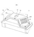
- FIG. 3 is a bottom perspective view of the outer casing 50.
- FIG. 4 is a bottom plan view of the exterior housing 50.
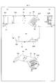
- FIG. 5 is a structural explanatory view of the bottom cover 60, including a plan view (a), an inner surface perspective view (b) of the bottom cover 60, a left perspective view (c), a right perspective view (d), and an external perspective view. (E) is illustrated in association with each other.
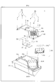
- FIG. 6 is an assembly explanatory diagram of the bottom cover 60.
- FIG. 7 is a sectional view taken along line AA in FIG.
- the outer casing 50 is formed by covering the bottom surface of the outer case 51 with a bottom cover 60.
- the bottom cover 60 includes a bottom plane 61 and a bottom first inclined surface 62R that is inclined from one side (the right side in FIG. 3) of the bottom plane 61 toward one side (the right side in FIG. 3) of the outer case 51. And a bottom second inclined surface 62L that is inclined from the other side portion (left side in FIG. 3) of the bottom plane 61 toward the other side portion (left side in FIG. 3) of the exterior case 51.
- the bottom cover 60 is made of a material having higher thermal conductivity than air, for example, a metal material such as iron, aluminum or copper, or a non-metal material such as ceramic.
- a fin 63 formed by arranging substantially triangular plate-shaped members is provided on the bottom first inclined surface 62R. Further, the bottom plane 61 is formed with a recess 64 that is recessed toward the inner space side of the outer case 51.
- the outer casing 50 is preferably in a substantially hermetically sealed state when the upper cover 52 and the bottom cover 60 are fixed to the outer casing 51. Therefore, no vent hole is formed in any of the exterior housing 50, the top cover 52, and the bottom cover 60. Therefore, it is required to devise a method of radiating the heat inside the outer casing 50 to the outside of the outer casing 50.
- the fins 63 and the recesses 64 described above are members for improving the heat dissipation performance of the exterior housing 50. Details will be described later.
- the bottom of the outer case 51 is formed so as to project in the depth direction with reference to the upper part of the outer case 51 to which the upper cover 52 is attached.
- the substrate holding surface 51b at the farthest position in the depth direction with the upper portion of the outer casing 51 as a reference, and one side portion (right side in FIG. 6) of the substrate holding surface 51b from the outer casing 51 to the outer case 51.
- the case first inclined surface 51R inclined toward the other side portion (right side in FIG. 6) and the other side portion (FIG. 6) from the other side portion (left side in FIG. 6) of the substrate holding surface 51b.
- a case second inclined surface 51L that inclines toward the left side).
- the case first inclined surface 51R is formed with a mounting opening 51R1 for mounting the image display device 30.
- the image display device 30 includes a backlight 31a, a light guide 31b that guides the light emitted from the backlight 31a to the LCD panel 31c, and an LCD panel 31c on which a display object is displayed.
- a backlight 31a a light guide 31b that guides the light emitted from the backlight 31a to the LCD panel 31c
- an LCD panel 31c on which a display object is displayed.
- the backlight 31a for example, a relatively inexpensive and highly reliable LED (Light Emitting Diode) substrate is used as a solid-state light source.
- the backlight 31a is a surface emitting type in order to increase the output.
- the image display device 30 is attached by fitting the LCD panel 31c into the attachment opening 51R1 of the outer case 51. Therefore, the image display device 30 is attached to the outer case 51 with the backlight 31a exposed.
- the inner surface of the bottom first inclined surface 62R faces the backlight 31a. Therefore, the heat generated in the backlight 31a is transmitted to the bottom first inclined surface 62R earlier than the other parts of the bottom cover 60. Since the fins 63 are formed on the outer surface of the bottom first inclined surface 62R, the heat of the backlight 31a transmitted to the bottom first inclined surface 62R is radiated from the fins 63, and the heat radiation performance is improved.
- the HUD 1 is configured by accommodating a CPU (control circuit) 71 that controls the mirror drive unit 44 and the image display device 30 and a main board 70 on which the CPU 71 is mounted in an exterior housing 50.
- the image display device 30 displays a display object on the LCD panel 31c based on the image signal input from the main substrate 70 via the flexible cable, and emits image light by modulating the light from the backlight 31a.
- the main board 70 is fixed to the board holding surface 51 b of the outer case 51 with screws (fastening members) 75.
- a thermal conductive sheet 79 having a thermal conductivity higher than that of air is placed on the CPU 71. Then, the bottom cover 60 is fixed to the outer case 51 using the screws 65.
- the depth of the recess of the recess 64 is such that no space is formed between the bottom surface of the recess 64 and the CPU 71 via the heat conductive sheet 79. As a result, it is possible to suppress the formation of an air layer in the heat transfer path from the CPU 71 to the bottom cover 60 via the heat conductive sheet 79, and further improve the heat conductivity.
- the upper cover 52, the outer case 51, and the bottom cover 60 do not have openings such as ventilation holes, and the outer casing 50 is hermetically sealed in a combination of these,
- the dustproof property can be improved.
- the term “sealed” as used herein means that the bottom surface of the outer case 51 and the image display device 30 can be housed separately from the outer space of the outer housing 50 in a state where the bottom cover 60 is fixed to the outer case 51 with the screws 75.
- it is desirable that the airtightness is high, but it is not the intention to demand the airtightness by interposing a packing between the outer case 51 and the bottom cover 60, for example.
- the internal space becomes narrower, and the backlight 31a, which is a heat source, and the CPU 71, which requires heat countermeasures, have to be placed close to each other. Therefore, in combination with the hermeticity of the outer casing 50, it is particularly necessary to take measures against heat from the CPU 71.
- the heat generated from the backlight 31a can be radiated from the fins 63 of the bottom cover 60 earlier. As a result, it is possible to prevent heat from staying inside the exterior housing 50.
- the CPU 71 itself also generates heat, but the heat can be transmitted to the bottom cover 60 via the heat conductive sheet 79. This further suppresses heat from being trapped inside the exterior housing 50, and suppresses the temperature rise of the CPU 71.
- the fins 63 function as a rib structure of the bottom cover 60. As a result, the strength of the bottom cover 60 can be increased.
- FIGS. 8 and 9 are structural explanatory views of the bottom covers 60a and 60b, and are a plan view (a), an inner surface perspective view (b) of the bottom cover 60, a left perspective view (c), and a right perspective view (d). , And an external perspective view (e) are shown in association with each other.
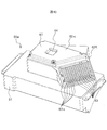
- FIG. 10 is an external perspective view of the bottom cover 60c.
- the shape of the fins 63a of the bottom cover 60a shown in FIG. 8 is different from that of the fins 63 of the bottom cover 60 described above.
- the bottom cover 60a is provided with a fin 63a in which a plurality of continuous protrusions are arranged in a row extending from the bottom first inclined surface 62R, the bottom flat surface 61, and the bottom second inclined surface 62L.
- the bottom cover 60b shown in FIG. 9 differs from the fin 63 of the bottom cover 60 described above in the shape and installation position of the fins 63b.
- the bottom cover 60b is provided with fins 63b in which a plurality of rows of protrusions arranged substantially parallel to the width direction of the bottom plane 61 are arranged.
- the fin may not be formed on the outer surface of the facing surface of the backlight 31a (for example, the bottom first inclined surface 62R). In that case, fins may be provided at other places on the bottom cover 60b.
- the bottom cover 60c shown in FIG. 10 does not include the bottom second inclined surface 62L in the above-mentioned bottom cover 60, and only the bottom first inclined surface 62R is formed continuously with the bottom flat surface 61. Then, a plurality of plate members are arranged on the bottom first inclined surface 62R to form the fin 63c. The weight can be reduced with respect to the one provided with the bottom second inclined surface 62L.
- HUD 2 vehicle 3: windshield 5: driver 30: image display device 31a: backlight 31b: light guide 31c: LCD panel 40: virtual image optical system 41: lens unit 42: reflection mirror 43: concave mirror 44: mirror drive Part 50: Exterior case 51: Exterior case 51L: Case second inclined surface 51R: Case first inclined surface 51R1: Mounting opening 51b: Substrate holding surface 52: Top cover 52a: Emission opening 53: Antiglare plate 60: Bottom cover 60a: Bottom cover 60b: Bottom cover 60c: Bottom cover 61: Bottom flat surface 62L: Bottom second inclined surface 62R: Bottom first inclined surface 63: Fin 63a: Fin 63b: Fin 64: Recess 65: Screw 70: Main Board 71: CPU 75: Screw 79: Thermally conductive sheet 80: Virtual image L: Optical path
Landscapes
- Physics & Mathematics (AREA)
- Engineering & Computer Science (AREA)
- Chemical & Material Sciences (AREA)
- Mechanical Engineering (AREA)
- General Physics & Mathematics (AREA)
- Transportation (AREA)
- Combustion & Propulsion (AREA)
- Nonlinear Science (AREA)
- Optics & Photonics (AREA)
- Crystallography & Structural Chemistry (AREA)
- Microelectronics & Electronic Packaging (AREA)
- Mathematical Physics (AREA)
- Thermal Sciences (AREA)
- Instrument Panels (AREA)
- Cooling Or The Like Of Electrical Apparatus (AREA)
- Mounting Of Printed Circuit Boards And The Like (AREA)
Abstract
ヘッドアップディスプレイ1は、バックライト31a及びLCDパネル31cを含む映像表示装置30と、LCDパネルから出射した映像光の光路Lを形成する虚像光学系40と、映像表示装置及び虚像光学系を収容する外装筐体50と、を備え、外装筐体は、虚像光学系を収容すると共に映像表示装置が取り付けられる外装ケース51と、外装ケースにおいて映像光が出射する上部を覆う上部カバー52と、外装ケースの底部を覆う底部カバー60と、を備え、底部カバー60は、外装ケースに固定された状態において、外装ケースの底面と映像表示装置とを外装筐体の外部空間から隔離して収容し、底部カバーにおける外表面にはフィン63が形成される。
Description
本発明は、ヘッドアップディスプレイに関する。
自動車等の乗り物において、通常は、車速やエンジン回転数等の情報は、ダッシュボード内の計器盤(インパネ)に表示される。また、カーナビゲーション等の画面は、ダッシュボードに組み込まれもしくはダッシュボード上に設置されたディスプレイに表示される。そこで、運転者がこれらの情報を視認する場合に視線を大きく移動させることを抑制するための技術として、車速等の情報やカーナビゲーションに係る指示等の情報をフロントガラス(ウィンドシールド)等に投射して虚像を表示するヘッドアップディスプレイ(Head Up Display、以下では「HUD」と記載する場合がある)が知られている。
HUDが太陽光の影響を受けて高温になると、HUDの筐体内に収容された光学部品や液晶パネル(LCD)が耐熱温度以上に上昇し、破損する恐れがある。そこで、特許文献1には、HUDに備えられた表示装置の耐熱性を向上させるための技術として、「表示ユニットは、画像に対応する表示光を発する表示面を含む表示部材と、表示部材の表示面の、表示領域を通過する表示光を遮らない位置に配置される熱伝導性をもつ蓄熱部材と、表示部材と蓄熱部材の間に設けられる熱伝導性接着剤から組成される熱伝導性接着層と、を備える(要約抜粋)」との記載がある。
HUDの筐体内には、レンズ、液晶パネル及びバックライトとしてのLED等の光学部品が収容される。太陽光やLEDから生じる熱が筐体内部にこもり、これらの光学部品を破損することを避けるために、筐体壁に外気の通風口を設けることも考えられる。しかし、通風口を設けると、光路上を塵が舞い、光学部品に塵が付着するという懸念がある。
加えて、ダッシュボード内の限られた空間にHUDを収容する必要から、HUDの大きさには制約がある。従って、HUDの実用化に際しては、放熱性及び防塵性の向上に加えて小型化も全て満たしたいという要望がある。しかし特許文献1は、LCDの表示面についての耐熱性の向上だけを目的としており、上記要望に応えることができていない。
そこで本発明は、放熱性及び防塵性の向上に加え小型化を含む実装化に要求される性能を追求したHUDを提供することを目的とする。
上記課題を解決するために、本発明は、請求の範囲に記載の構成を有する。その一例をあげるならば、本発明は、運転者に対して虚像を表示するヘッドアップディスプレイであって、バックライト及び液晶パネルを含む映像表示装置と、前記液晶パネルから出射した映像光の光路を形成する虚像光学系と、前記映像表示装置及び前記虚像光学系を収容する外装筐体と、を備え、前記外装筐体は、前記虚像光学系を収容すると共に前記映像表示装置が取り付けられる外装ケースと、前記外装ケースにおいて前記映像光が出射する上部を覆う上部カバーと、前記外装ケースの底部を覆う底部カバーと、を備え、前記底部カバーは、前記外装ケースに固定された状態において、前記外装ケースの底面と前記映像表示装置とを前記外装筐体の外部空間から隔離して収容し、前記底部カバーにおける外表面にはフィンが備えられる、ことを特徴とする。
本発明によれば、放熱性及び防塵性の向上に加え小型化を含む実装化に要求される性能を追求したHUDを提供することができる。なお、上述した以外の目的、構成、効果については下記実施形態において明らかにされる。
以下、本発明の実施形態を図面に基づいて詳細に説明する。なお、全図において同一部材には原則として同一の符号を付し、その繰り返しの説明は省略する。一方で、ある図において符号を付して説明した部位について、他の図の説明の際に再度の図示はしないが同一の符号を付して言及する場合がある。また、以下に示す各実施形態では、ヘッドアップディスプレイ(HUD)が自動車等の車両に設置される場合を例として説明するが、電車や航空機等の他の乗り物にも適用可能である。また、乗り物以外の用途に用いるHUDにも適用可能である。
図1は、本実施形態に係るヘッドアップディスプレイ(HUD)1の概略構成図である。図2は、HUD1の外装筐体50内の矢印で示した光路Lを示す斜視図である。
図1に示すように、HUD1は、LCD(Liquid Crystal Display)パネル31cを含む映像表示装置30と、映像表示装置30から出射される映像光を拡大するレンズユニット41、光路Lを折り返す反射ミラー42、及び映像光に含まれる映像情報を拡大投射するための凹面ミラー43を含む虚像光学系40を構成する光学部品と、凹面ミラー43を回転駆動するミラー駆動部44と、これらの光学部品、ミラー駆動部44、及び映像表示装置30を収容する外装筐体50とを備える。外装筐体50の外表面にはフィン63が形成される。
凹面ミラー43はミラー駆動部44により回動する。これにより、凹面ミラー43はウィンドシールド3に向けて映像光を反射する角度を変更する。映像光は凹面ミラー43により反射され、車両2のウィンドシールド3に投射される。ウィンドシールド3に投射された映像光が運転者5の目に入射することで、運転者5は車両2の前方に虚像80を視認する。
被投射部材はウィンドシールド3に限らず、映像光が投射される部材であれば、コンバイナなど他の部材とすることができる。
レンズユニット41は、光路Lの光学的な距離を調整したり、映像光に含まれる表示オブジェクト像の歪み補正を行うレンズ群である。
映像表示装置30からの映像光の出射方向に沿って、映像表示装置30から近い順にレンズユニット41、反射ミラー42、凹面ミラー43が配置されて虚像光学系40を形成し、外装筐体50の内部に収容される。
図2に示すように、外装筐体50は、光学部品を収容する外装ケース51と、外装ケース51の上部を覆う上部カバー52と、外装ケース51の底部開口を覆う底部カバー60(図3参照)と含んで形成される。
上部カバー52には、映像光が出射する出射開口部52aが形成される。出射開口部52aは、防眩板53で覆われる。
LCDパネル31cから出射した映像光は、レンズユニット41(図2では図示を省略)を通過して反射ミラー42で光路Lを折り返し、凹面ミラー43に向かう。そして凹面ミラー43で更に反射され、防眩板53を透過して外装筐体50から出射する。
外装筐体50内で光路Lを折り返すと、バックライト31a(図6参照)から運転者5の目までの光路Lをより長く形成することができる。光路Lを長くすると運転者5からみてより遠くに虚像80が表示される。運転者5が運転中に注視している視点は、一般に走行速度が速いほど遠くなる。HUD1は、光路Lを折り曲げることで虚像距離を長くし、運転中に遠方を注視している運転者5が、虚像80を視認するために行う視点移動の距離をより短くすることができる。
図3は、外装筐体50の底部斜視図である。図4は、外装筐体50の底部平面図である。図5は、底部カバー60の構造説明図であり、平面図(a)、底部カバー60の内表面斜視図(b)、左斜視図(c)、右斜視図(d)、及び外観斜視図(e)を関連づけて図示する。図6は、底部カバー60の組み立て説明図である。図7は、図4におけるA-A断面図である。
図3、図4、図5に示すように、外装筐体50は、外装ケース51の底面を底部カバー60で覆って形成される。底部カバー60は、底部平面61と、底部平面61の一方の側部(図3における右側)から外装ケース51の一方の側部(図3における右側)に向かって傾斜する底部第1傾斜面62Rと、底部平面61の他方の側部(図3における左側)から外装ケース51の他方の側部(図3における左側)に向かって傾斜する底部第2傾斜面62Lとを含んで形成される。
底部カバー60は、熱伝導性が空気よりも高い材質、例えば、鉄、アルミニウム、銅などの金属材料や、セラミックなどの非金属材料を用いて構成される。
底部第1傾斜面62Rには、略三角形の板状部材を並べて形成されたフィン63が設けられる。また底部平面61には、外装ケース51の内部空間側に向かって凹んだ凹部64が形成される。外装筐体50は防塵性を高めるために、上部カバー52及び底部カバー60を外装ケース51に固定した状態において、ほぼ密閉状態となることが望ましい。従って、外装筐体50、上部カバー52及び底部カバー60のいずれにも通気孔は形成されない。そのため、外装筐体50内の熱を、外装筐体50の外部に放熱する工夫が求められる。上述のフィン63及び凹部64は、外装筐体50の放熱性能を向上させるための部材である。詳しくは後述する。
図6に示すように、外装ケース51の底部は、上部カバー52が取り付けられる外装ケース51の上部を基準として奥行き方向に突出して形成される。具体的には、外装ケース51の上部を基準として奥行き方向に沿って最も離れた位置にある基板保持面51bと、基板保持面51bの一方の側部(図6における右側)から外装ケース51の他方の側部(図6における右側)に向かって傾斜するケース第1傾斜面51Rと、基板保持面51bの他方の側部(図6における左側)から外装ケース51の他方の側部(図6における左側)に向かって傾斜するケース第2傾斜面51Lと、を備える。
ケース第1傾斜面51Rは、映像表示装置30を取り付けるための取付開口部51R1が形成される。映像表示装置30は、バックライト31aと、バックライト31aの発光光をLCDパネル31cに導く導光体31bと、表示オブジェクトが表示されるLCDパネル31cとを含んで構成される。バックライト31aから発せられた発光光がLCDパネル31cを透過して出射する際に表示オブジェクト像を含んだ映像光が形成され、LCDパネル31cから映像光が出射する。
バックライト31aは、例えば、固体光源として比較的安価で信頼性の高いLED(Light Emitting Diode)基板を用いる。バックライト31aは、高出力化するために面発光型とする。
映像表示装置30は、外装ケース51の取付開口部51R1にLCDパネル31cをはめ込んで取り付けられる。従って、映像表示装置30は、バックライト31aが露出した状態で外装ケース51に取り付けられる。この状態で、底部カバー60を外装ケース51に被せると、底部第1傾斜面62Rの内表面がバックライト31aに対向する。よって、バックライト31aで生じた熱は、底部カバー60の他の部分に比べて底部第1傾斜面62Rにより早く伝わる。底部第1傾斜面62Rの外表面にはフィン63が形成されるので、底部第1傾斜面62Rに伝わったバックライト31aの熱は、フィン63から放熱され、放熱性能が向上する。
HUD1は、ミラー駆動部44及び映像表示装置30を制御するCPU(制御回路)71と、これを搭載したメイン基板70とを外装筐体50に収容して構成される。映像表示装置30は、フレキシブルケーブルを介してメイン基板70から入力された映像信号に基づいてLCDパネル31cに表示オブジェクトを表示し、バックライト31aからの光を変調することで映像光を出射する。
図6に示すように、メイン基板70は、外装ケース51の基板保持面51bに対してねじ(締結部材)75で固定される。CPU71上には空気よりも熱伝導性が高い熱伝導性シート79を載置する。そして、外装ケース51に底部カバー60をねじ65を用いて固定する。
図7に示すように、凹部64は、CPU71と対向する位置に設けられるので、CPU71から熱伝導性シート79を介して底部カバー60に至る熱伝達経路が形成される。
凹部64のくぼみの深さは、凹部64の底面と熱伝導性シート79を介してCPU71との間に空隙が生じない深さであることが望ましい。これによりCPU71から熱伝導性シート79を介して底部カバー60に至る熱伝達経路に空気層が形成されることを抑制し、熱伝導性をより向上させることができる。
本実施形態に係るHUD1によれば、上部カバー52、外装ケース51、及び底部カバー60は通気孔のような開口部を備えず、これらを組み合わせた状態で外装筐体50は密閉されるので、防塵性を向上させることができる。ここでいう密閉とは、外装ケース51にねじ75を用いて底部カバー60を固定した状態において、外装ケース51の底面と映像表示装置30とが外装筐体50の外部空間から隔離して収容できればよく、厳密な気密性を要求する意図ではない。もちろん、気密性が高い方が望ましいが、例えば外装ケース51と底部カバー60との間にパッキンを介在させて気密性を担保することまでは要求する意図ではない。
一方、HUD1の小型化を図ることにより、内部空間が狭くなり、熱源となるバックライト31aと熱対策が必要なCPU71とを近づけて配置せざるを得なくなる。そのため、外装筐体50の密閉性と相まって、特にCPU71の熱対策が必要となる。
ここで、底部カバー60におけるバックライト31aに対向する部位の外表面にフィン63を備えることで、より早くバックライト31aから生じた熱を底部カバー60のフィン63から放熱することができる。これにより、外装筐体50内部に熱がこもることを抑制する。
更に、CPU71自体も発熱するが、その熱を熱伝導性シート79を介して底部カバー60に伝達することができる。これにより、外装筐体50内部に熱がこもることを更に抑制し、CPU71の温度上昇を抑制する。
また、フィン63を底部カバー60に一体成型することにより、フィン63が底部カバー60のリブ構造として機能する。これにより、底部カバー60の強度を高めることができる。
上記実施形態は本発明を限定するものではなく、本発明の趣旨を逸脱しない範囲での変更態様は本発明の技術的範囲に属する。
図8、図9を参照して、他の実施形態について説明する。図8、図9は、底部カバー60a、60bの構造説明図であり、平面図(a)、底部カバー60の内表面斜視図(b)、左斜視図(c)、右斜視図(d)、及び外観斜視図(e)を関連づけて図示する。図10は、底部カバー60cの外観斜視図である。
図8に示す底部カバー60aは、上述の底部カバー60のフィン63と比べてフィン63aの形状が異なる。底部カバー60aには、底部第1傾斜面62R、底部平面61、及び底部第2傾斜面62Lにかけて連続する突起を複数列並べたフィン63aが形成される。底部カバー60aの長手方向に亘ってフィン63aを設けてリブ構造をなすことにより、底部カバー60aの強度を増すことができる。また、底部カバー60のフィン63よりも表面積を増やすことにより、放熱性を向上させることができる。
図9に示す底部カバー60bは、上述の底部カバー60のフィン63と比べてフィン63bの形状及び設置位置が異なる。底部カバー60bには、底部平面61の幅方向と略平行な突起を複数列配列したフィン63bが形成される。HUD1が搭載されるダッシュボード内側の形状によっては、バックライト31aの対向面(例えば底部第1傾斜面62R)の外表面にフィンが形成できないこともある。その場合は、底部カバー60bの他の場所にフィンを設けてもよい。
図10に示す底部カバー60cは、上述の底部カバー60において、底部第2傾斜面62Lを備えず、底部平面61に連続して底部第1傾斜面62Rのみを形成する。そして、底部第1傾斜面62Rに板状部材を複数列してフィン63cを形成する。底部第2傾斜面62Lを備えたものに対して軽量化できる。
1 :HUD
2 :車両
3 :ウィンドシールド
5 :運転者
30 :映像表示装置
31a :バックライト
31b :導光体
31c :LCDパネル
40 :虚像光学系
41 :レンズユニット
42 :反射ミラー
43 :凹面ミラー
44 :ミラー駆動部
50 :外装筐体
51 :外装ケース
51L :ケース第2傾斜面
51R :ケース第1傾斜面
51R1 :取付開口部
51b :基板保持面
52 :上部カバー
52a :出射開口部
53 :防眩板
60 :底部カバー
60a :底部カバー
60b :底部カバー
60c :底部カバー
61 :底部平面
62L :底部第2傾斜面
62R :底部第1傾斜面
63 :フィン
63a :フィン
63b :フィン
64 :凹部
65 :ねじ
70 :メイン基板
71 :CPU
75 :ねじ
79 :熱伝導性シート
80 :虚像
L :光路
2 :車両
3 :ウィンドシールド
5 :運転者
30 :映像表示装置
31a :バックライト
31b :導光体
31c :LCDパネル
40 :虚像光学系
41 :レンズユニット
42 :反射ミラー
43 :凹面ミラー
44 :ミラー駆動部
50 :外装筐体
51 :外装ケース
51L :ケース第2傾斜面
51R :ケース第1傾斜面
51R1 :取付開口部
51b :基板保持面
52 :上部カバー
52a :出射開口部
53 :防眩板
60 :底部カバー
60a :底部カバー
60b :底部カバー
60c :底部カバー
61 :底部平面
62L :底部第2傾斜面
62R :底部第1傾斜面
63 :フィン
63a :フィン
63b :フィン
64 :凹部
65 :ねじ
70 :メイン基板
71 :CPU
75 :ねじ
79 :熱伝導性シート
80 :虚像
L :光路
Claims (6)
- 運転者に対して虚像を表示するヘッドアップディスプレイであって、
バックライト及び液晶パネルを含む映像表示装置と、
前記液晶パネルから出射した映像光の光路を形成する虚像光学系と、
前記映像表示装置及び前記虚像光学系を収容する外装筐体と、を備え、
前記外装筐体は、前記虚像光学系を収容すると共に前記映像表示装置が取り付けられる外装ケースと、
前記外装ケースにおいて前記映像光が出射する上部を覆う上部カバーと、
前記外装ケースの底部を覆う底部カバーと、を備え、
前記底部カバーは、前記外装ケースに固定された状態において、前記外装ケースの底面と前記映像表示装置とを前記外装筐体の外部空間から隔離して収容し、前記底部カバーにおける外表面にはフィンが備えられる、
ことを特徴とするヘッドアップディスプレイ。 - 請求項1に記載のヘッドアップディスプレイにおいて、
前記映像表示装置は、前記液晶パネルを前記外装ケースの内部空間に露出させ、前記バックライトを前記外装ケースの外部に露出させて前記外装ケースに取り付けられ、
前記フィンは、前記底部カバーにおける前記バックライトとの対向面の外表面に形成される、
ことを特徴とするヘッドアップディスプレイ。 - 請求項1に記載のヘッドアップディスプレイにおいて、
前記映像表示装置の制御を行う制御回路及び当該制御回路を搭載したメイン基板を更に備え、
前記外装ケースは、前記底部カバーと対向する面に前記メイン基板を保持する基板保持面を含み、
前記基板保持面に保持された前記メイン基板上の前記制御回路と前記底部カバーとの間に、空気よりも熱伝導性が高い熱伝導性シートが配置される、
ことを特徴とするヘッドアップディスプレイ。 - 請求項3に記載のヘッドアップディスプレイにおいて、
前記底部カバーにおける前記制御回路と対向する面に、前記制御回路に向かって凹んだ凹部が形成される、
ことを特徴とするヘッドアップディスプレイ。 - 請求項2に記載のヘッドアップディスプレイにおいて、
前記映像表示装置の制御を行う制御回路及び当該制御回路を搭載したメイン基板を更に備え、
前記外装ケースは、前記底部カバーと対向する面に前記メイン基板を保持する基板保持面を含み、
前記基板保持面に保持された前記メイン基板上の前記制御回路と前記底部カバーとの間に、空気よりも熱伝導性が高い熱伝導性シートが配置される、
ことを特徴とするヘッドアップディスプレイ。 - 請求項5に記載のヘッドアップディスプレイにおいて、
前記底部カバーにおける前記制御回路と対向する面に、前記制御回路に向かって凹んだ凹部が形成される、
ことを特徴とするヘッドアップディスプレイ。
Priority Applications (4)
| Application Number | Priority Date | Filing Date | Title |
|---|---|---|---|
| CN201980090068.4A CN113330352A (zh) | 2019-02-22 | 2019-10-09 | 平视显示器 |
| US17/428,994 US11953681B2 (en) | 2019-02-22 | 2019-10-09 | Head-up display including heat dissipation |
| US18/595,494 US12259549B2 (en) | 2019-02-22 | 2024-03-05 | Vehicle including a virtual image optical system in a housing having heat dissipation |
| US19/059,345 US20250189789A1 (en) | 2019-02-22 | 2025-02-21 | Head-up display |
Applications Claiming Priority (2)
| Application Number | Priority Date | Filing Date | Title |
|---|---|---|---|
| JP2019030786A JP7474028B2 (ja) | 2019-02-22 | 2019-02-22 | ヘッドアップディスプレイ |
| JP2019-030786 | 2019-02-22 |
Related Child Applications (2)
| Application Number | Title | Priority Date | Filing Date |
|---|---|---|---|
| US17/428,994 A-371-Of-International US11953681B2 (en) | 2019-02-22 | 2019-10-09 | Head-up display including heat dissipation |
| US18/595,494 Continuation US12259549B2 (en) | 2019-02-22 | 2024-03-05 | Vehicle including a virtual image optical system in a housing having heat dissipation |
Publications (1)
| Publication Number | Publication Date |
|---|---|
| WO2020170495A1 true WO2020170495A1 (ja) | 2020-08-27 |
Family
ID=72143409
Family Applications (1)
| Application Number | Title | Priority Date | Filing Date |
|---|---|---|---|
| PCT/JP2019/039845 Ceased WO2020170495A1 (ja) | 2019-02-22 | 2019-10-09 | ヘッドアップディスプレイ |
Country Status (4)
| Country | Link |
|---|---|
| US (3) | US11953681B2 (ja) |
| JP (1) | JP7474028B2 (ja) |
| CN (1) | CN113330352A (ja) |
| WO (1) | WO2020170495A1 (ja) |
Cited By (1)
| Publication number | Priority date | Publication date | Assignee | Title |
|---|---|---|---|---|
| CN116406335A (zh) * | 2021-09-02 | 2023-07-07 | 京东方科技集团股份有限公司 | 投影组件、显示系统及车辆 |
Families Citing this family (1)
| Publication number | Priority date | Publication date | Assignee | Title |
|---|---|---|---|---|
| JP7474028B2 (ja) * | 2019-02-22 | 2024-04-24 | マクセル株式会社 | ヘッドアップディスプレイ |
Citations (2)
| Publication number | Priority date | Publication date | Assignee | Title |
|---|---|---|---|---|
| JP2007180141A (ja) * | 2005-12-27 | 2007-07-12 | Nippon Seiki Co Ltd | 表示装置 |
| JP2017537354A (ja) * | 2014-11-28 | 2017-12-14 | ヴァレオ、コンフォート、アンド、ドライビング、アシスタンスValeo Comfort And Driving Assistance | バックライト装置、とりわけヘッドアップディスプレイ用のバックライト装置及び自動車用ヘッドアップディスプレイ |
Family Cites Families (11)
| Publication number | Priority date | Publication date | Assignee | Title |
|---|---|---|---|---|
| JPH02138796A (ja) * | 1988-11-18 | 1990-05-28 | Matsushita Electric Ind Co Ltd | 電子機器 |
| JPH0730280A (ja) * | 1993-07-09 | 1995-01-31 | Sony Corp | シールドケース |
| WO2005064577A1 (ja) * | 2003-12-25 | 2005-07-14 | Nippon Seiki Co., Ltd. | 表示装置 |
| JP4525320B2 (ja) * | 2004-12-02 | 2010-08-18 | 船井電機株式会社 | シールド装置及びシールド方法 |
| JP6222125B2 (ja) * | 2015-01-28 | 2017-11-01 | Tdk株式会社 | 電子機器 |
| JP6515041B2 (ja) * | 2016-01-19 | 2019-05-15 | 日立オートモティブシステムズ株式会社 | 電子制御装置 |
| FR3054046B1 (fr) * | 2016-06-29 | 2018-08-17 | Valeo Comfort And Driving Assistance | Dispositif de generation d'images et afficheur tete haute associe |
| JP6766525B2 (ja) | 2016-08-30 | 2020-10-14 | 日本精機株式会社 | 表示装置 |
| US11061229B2 (en) * | 2017-09-27 | 2021-07-13 | Nippon Seiki Co., Ltd. | Head-up display |
| JP7474028B2 (ja) * | 2019-02-22 | 2024-04-24 | マクセル株式会社 | ヘッドアップディスプレイ |
| JP7068223B2 (ja) * | 2019-03-28 | 2022-05-16 | マクセル株式会社 | ヘッドアップディスプレイ |
-
2019
- 2019-02-22 JP JP2019030786A patent/JP7474028B2/ja active Active
- 2019-10-09 US US17/428,994 patent/US11953681B2/en active Active
- 2019-10-09 WO PCT/JP2019/039845 patent/WO2020170495A1/ja not_active Ceased
- 2019-10-09 CN CN201980090068.4A patent/CN113330352A/zh active Pending
-
2024
- 2024-03-05 US US18/595,494 patent/US12259549B2/en active Active
-
2025
- 2025-02-21 US US19/059,345 patent/US20250189789A1/en active Pending
Patent Citations (2)
| Publication number | Priority date | Publication date | Assignee | Title |
|---|---|---|---|---|
| JP2007180141A (ja) * | 2005-12-27 | 2007-07-12 | Nippon Seiki Co Ltd | 表示装置 |
| JP2017537354A (ja) * | 2014-11-28 | 2017-12-14 | ヴァレオ、コンフォート、アンド、ドライビング、アシスタンスValeo Comfort And Driving Assistance | バックライト装置、とりわけヘッドアップディスプレイ用のバックライト装置及び自動車用ヘッドアップディスプレイ |
Cited By (1)
| Publication number | Priority date | Publication date | Assignee | Title |
|---|---|---|---|---|
| CN116406335A (zh) * | 2021-09-02 | 2023-07-07 | 京东方科技集团股份有限公司 | 投影组件、显示系统及车辆 |
Also Published As
| Publication number | Publication date |
|---|---|
| CN113330352A (zh) | 2021-08-31 |
| US20220075190A1 (en) | 2022-03-10 |
| US12259549B2 (en) | 2025-03-25 |
| JP7474028B2 (ja) | 2024-04-24 |
| US20250189789A1 (en) | 2025-06-12 |
| US11953681B2 (en) | 2024-04-09 |
| US20240201492A1 (en) | 2024-06-20 |
| JP2020134828A (ja) | 2020-08-31 |
Similar Documents
| Publication | Publication Date | Title |
|---|---|---|
| US11789324B2 (en) | Display, display system, image projection system, and movable object | |
| CN110770635B (zh) | 平视显示装置 | |
| TWI582465B (zh) | 抬頭顯示系統 | |
| US20250189789A1 (en) | Head-up display | |
| JP2009288484A (ja) | 発光表示装置 | |
| JP5104694B2 (ja) | ヘッドアップディスプレイ装置 | |
| US11971545B2 (en) | Vehicular display device | |
| JP7068223B2 (ja) | ヘッドアップディスプレイ | |
| EP3163354A1 (en) | Head-up display device | |
| WO2020166293A1 (ja) | 虚像表示装置 | |
| WO2013129041A1 (ja) | ヘッドアップディスプレイ装置 | |
| JP2018140693A (ja) | 車両用ヘッドアップディスプレイ装置 | |
| US20200387030A1 (en) | Image generating device and associated head-up display | |
| US20240377631A1 (en) | Display unit and vehicular display device | |
| US12623539B2 (en) | Vehicle display apparatus | |
| JP2024128395A (ja) | 画像照射装置 | |
| US12596253B2 (en) | Vehicular display device | |
| US20240329373A1 (en) | Display device | |
| JP4873130B2 (ja) | 表示装置 | |
| US12619072B2 (en) | Image-generating device | |
| EP4311978B1 (en) | Display | |
| US20250389956A1 (en) | Image display device | |
| WO2022045048A1 (ja) | 画像投影装置 |
Legal Events
| Date | Code | Title | Description |
|---|---|---|---|
| 121 | Ep: the epo has been informed by wipo that ep was designated in this application |
Ref document number: 19916019 Country of ref document: EP Kind code of ref document: A1 |
|
| NENP | Non-entry into the national phase |
Ref country code: DE |
|
| 122 | Ep: pct application non-entry in european phase |
Ref document number: 19916019 Country of ref document: EP Kind code of ref document: A1 |