WO2020170372A1 - 鞍乗型車両 - Google Patents
鞍乗型車両 Download PDFInfo
- Publication number
- WO2020170372A1 WO2020170372A1 PCT/JP2019/006374 JP2019006374W WO2020170372A1 WO 2020170372 A1 WO2020170372 A1 WO 2020170372A1 JP 2019006374 W JP2019006374 W JP 2019006374W WO 2020170372 A1 WO2020170372 A1 WO 2020170372A1
- Authority
- WO
- WIPO (PCT)
- Prior art keywords
- control unit
- type vehicle
- vehicle body
- meter
- communication
- Prior art date
- Legal status (The legal status is an assumption and is not a legal conclusion. Google has not performed a legal analysis and makes no representation as to the accuracy of the status listed.)
- Ceased
Links
Images


Classifications
-
- B—PERFORMING OPERATIONS; TRANSPORTING
- B62—LAND VEHICLES FOR TRAVELLING OTHERWISE THAN ON RAILS
- B62J—CYCLE SADDLES OR SEATS; AUXILIARY DEVICES OR ACCESSORIES SPECIALLY ADAPTED TO CYCLES AND NOT OTHERWISE PROVIDED FOR, e.g. ARTICLE CARRIERS OR CYCLE PROTECTORS
- B62J99/00—Subject matter not provided for in other groups of this subclass
Definitions
- the present invention relates to a saddle type vehicle.
- Patent Document 1 a wire harness for sending electric power for lighting equipment to each lighting equipment is arranged long from a front end portion to a rear end portion of a vehicle, and a conductor wire having a thickness corresponding to a capacity of an upstream fuse is provided. Since it is used, in the case of a thick conductive wire, there has been a problem that a large amount of conductive dose is required, resulting in high cost, high cost and increased weight.
- An object of the present invention is to provide a straddle-type vehicle that can be reduced in weight by reducing the amount of guided radiation.
- a straddle-type vehicle includes a plurality of control units (81, 82) in a saddle-ride type vehicle including a control unit (81, 82) that generates an output signal in accordance with an input signal, and the plurality of control units (81 , 82) each include a communication unit (97, 98) that communicates with each other, and the communication units (97, 98) are arranged at least at two positions in a front portion and a rear portion of the vehicle body.
- the meter (67) is arranged in the front part of the vehicle body, the lighting device (74) is arranged in the rear part of the vehicle body, and the communication unit (97, 98) is arranged in the meter (67) and the lighting device ( 74), respectively.
- the said communication part (97,98) is inside the said meter (67) and the said lighting device (74) in order to control the said meter (67) and the said lighting device (74), respectively. It may be connected to the control board (101, 102) arranged in.
- the communication units (97, 98) may be connected to each other by a local interconnect network (LIN).
- LIN local interconnect network
- an ECU (65) that performs engine control is connected to the plurality of communication units (97, 98) via the local interconnect network (LIN), and the ECU (65) and the ECU A controller area network (CAN) may be connected to the device control section (91) connected to (65). Further, in the above configuration, the control unit (81) may be arranged in the meter (67), and the control unit (81) may process the input from the handlebar switch (HS) with the highest priority.
- LIN local interconnect network
- CAN controller area network
- control unit (81) provided in the front portion of the vehicle body may be arranged in the headlight (61). Further, in the above configuration, the control unit (81) provided in the front portion of the vehicle body may process the input from the steering wheel switch (HS) with the highest priority.
- HS steering wheel switch
- the saddle-ride type vehicle includes a plurality of control units, and the plurality of control units each include a communication unit that communicates with each other. Since the communication units are arranged in at least two positions on a front portion and a rear portion of the vehicle body, a front portion of the vehicle body is provided. By controlling each by the control part of the rear part and the control part of the rear part, it is possible to reduce the lead wires of many circuits connecting the front part and the rear part of the vehicle body with the maximum path length, and a large weight saving effect is obtained.
- the meter is arranged in the front part of the vehicle body, the lighting device is arranged in the rear part of the vehicle body, and the communication part is arranged inside the meter and the lighting device, respectively, so that the lighting device is ensured to be waterproof.
- the communication unit is connected to the control board arranged inside the meter and the lighting device for controlling the meter and the lighting device, respectively, so that the communication unit is already used in the meter and the lighting device. By mounting the communication unit on the existing control board, the communication unit can be used, and existing parts can be diverted to reduce the cost.
- the communication units are connected by the local interconnect network (LIN), the communication units can be connected by a single line, and the cost can be reduced.
- an ECU that controls the engine is connected to the plurality of communication units via a local interconnect network (LIN), and a controller area network is provided between the ECU and the device control unit connected to the ECU. Since they are connected by (CAN), communication can be performed between each communication unit and the ECU.
- LIN local interconnect network
- control unit is arranged in the meter, and the control unit processes the input from the steering wheel switch with the highest priority.Therefore, in the steering wheel switch, when a sudden operation is required while driving the vehicle, By giving top priority to the input from the handlebar switch, it becomes possible to respond to sudden operation.
- the control unit provided in the front part of the vehicle body is arranged inside the headlight, the control unit is arranged inside the headlight whose waterproof property is ensured, thereby providing a new waterproof structure. Since it is not necessary to provide, it is possible to easily ensure waterproofness. Further, in the above configuration, the control unit provided in the front portion of the vehicle body processes the input from the steering wheel switch with the highest priority. Therefore, in the steering wheel switch, when a sudden operation is required while driving the vehicle, the steering wheel switch is operated. By giving top priority to the input from, it becomes possible to deal with sudden operations.
- FIG. 1 is a left side view showing a motorcycle according to an embodiment of the present invention.
- FIG. 2 is a block diagram showing the vehicle control device.
- FIG. 3 is a cross-sectional view showing the substrate arrangement structure in the headlight.
- FIG. 1 is a left side view showing a motorcycle 10 according to an embodiment of the present invention.
- the motorcycle 10 includes a body frame serving as a skeleton, a front wheel 13 supported at a front end of the body frame via a front fork 12, and a rear wheel 16 supported at a lower portion of the body frame via a power unit 14. ..
- the motorcycle 10 is a scooter-type straddle-type vehicle in which an occupant sits astride a seat 17 arranged above the power unit 14 and the rear wheel 16, and includes a vehicle body frame and a vehicle body cover 20 that covers the periphery thereof.
- a handle 21 is attached to an upper portion of the front fork 12, and a front wheel 13 is supported at a lower end portion thereof via an axle 22.
- the power unit 14 includes an engine 24 provided at a front portion and a continuously variable transmission 26 provided at a rear portion of a crankcase 25 of the engine 24, and a rear wheel 16 is attached to an output shaft 27 of the continuously variable transmission 26.
- An intake device 31 is connected to an upper portion of the cylinder head of the engine 24, and an exhaust device 32 is connected to a lower portion thereof.
- the intake device 31 includes an air cleaner 34 attached to an upper portion of the continuously variable transmission 26.
- the exhaust device 32 includes a muffler 37 connected to the rear end of the exhaust pipe extending from the cylinder head.
- a rear cushion unit 41 which is a shock absorber, is provided between the rear end portion of the power unit 14 and the rear portion of the vehicle body frame.
- a stand 43 is attached to the lower portion of the crankcase 42.
- the vehicle body cover 20 includes a front cover 51, a pair of left and right leg shields 52, a pair of left and right floor steps 53, a pair of left and right side skirts 54, a pair of left and right body covers 56, and a handle cover 57.
- the front cover 51 covers the front of the front fork 12 and the periphery of the headlight 61.
- the left and right leg shields 52 extend from the both side edges of the front cover 51 to the left and right rear and cover the legs of the driver sitting on the seat 17 from the front.
- the left and right floor steps 53 extend rearward from the lower portions of the left and right leg shields 52 and serve as a foot rest for the driver.
- a battery 63 is arranged below the left and right floor steps 53.
- the left and right side skirts 54 extend downward from both side edges of the left and right floor steps 53, respectively.
- the left and right body covers 56 cover the lower portions of both side portions of the seat 17.
- An ECU (engine control unit) 65 that controls the engine 24 is disposed inside the left and right body covers 56 in the vehicle width direction.
- the ECU 65 controls the fuel injection amount of the engine 24, the ignition timing, and the like based on information such as the engine speed, the throttle opening, and the intake air amount.
- the handle cover 57 covers the central portion of the handle 21.
- a meter 67 is arranged above the handle cover 57.
- the front wheel 13 is covered by the front fender 71 from above, and the rear wheel 16 is covered by the rear fender 72 from above.
- a combination light 74 including a stop light and a tail light is provided behind the seat 17 and above the rear fender 72.
- a front controller 81 and a rear controller 82 are housed in respective housings of a meter 67 provided at the front of the vehicle body and a combination light 74 provided at the rear of the vehicle.
- the meter 67 and the combination light 74 described above each include an LED light source and a substrate on which an LED light source and an electronic component for causing the LED light source to emit light are mounted.
- the front controller 81 and the rear controller 82 are connected by a single conductor wire 86.
- the front controller 81 mainly controls vehicle body accessories provided at the front of the vehicle body
- the rear controller 82 mainly controls vehicle body accessories provided at the rear of the vehicle body.
- the front controller 81 and the rear controller 82 are provided on a single or a plurality of substrates, respectively, and are integrally or separately provided on the substrates of the meter 67 and the combination light 74 described above.
- the front controller 81, the rear controller 82, and the conducting wire 86 described above constitute a LIN connection control device 88.
- the LIN connection control device 88 forms a LIN (Local Interconnect Network), and between each of the front control unit 81 and the rear control unit 82, multiplex communication in the LIN is performed via a conducting wire 86 drawn by a chain line. Done. Further, the ECU 65, the LIN connection control device 88, and the single conducting wire 87 connected to the conducting wire 86 (indicated by the chain line) form a part of the vehicle control device 90.
- the LIN does not require a communication speed as high as that of a CAN (Controller Area Network) described below, and only one conducting wire 86 connecting each of the front controller 81 and the rear controller 82 is required.
- CAN Controller Area Network
- the meter 67 is arranged in a portion close to the front end of the vehicle body and the combination light 74 is arranged in a portion close to the rear end of the vehicle body, substantially from the vehicle body front end portion to the vehicle body rear end portion.
- the power line of the equipment can be omitted.
- the front controller 81 and the rear controller 82 in the existing meter 67 and combination light 74 having the waterproof structure, respectively it is not necessary to add a special waterproof structure, and the cost increase can be suppressed. it can.
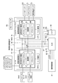
- FIG. 2 is a block diagram showing the vehicle control device 90.
- the vehicle control device 90 includes an ECU 65, a front controller 81, a rear controller 82, conductors 86 and 87, a device controller 91, and conductors 92 and 93.
- the device control unit 91 is connected to the ECU 65 via two conducting wires 92 and 93, and includes a control unit (drive system control unit, suspension control unit, or ABS control unit) that requires high responsiveness. It should be noted that the device control section 91 may be provided in plural (drive system control section, suspension control section, ABS control section, etc.).
- the positive electrode 63a and the negative electrode 63b of the battery 63 are a positive electrode side conducting wire 94 (a power source line and a line drawn by a solid line) and a negative electrode side conducting wire (a ground wire and a line drawn by a broken line), respectively. ) 95, it is connected to the front controller 81, the rear controller 82, the ECU 65, and the device controller 91.
- the front controller 81 is a high-side driver that includes a microcomputer (CPU (Central Processing Unit)) 93A, various drivers 96A such as an actuator driver, and a communication unit 97.
- the microcomputer (CPU) 93A, the driver 96A, and the communication unit 97 are attached to a meter board MCC (which is a first board 101 (see FIG. 3) to be described later in detail) arranged in the meter 67, which is a rear part. It is attached to a retrofit board (second board 102).
- a driver 96A and a communication unit 97 are connected to the microcomputer (CPU) 93A.
- the microcomputer (CPU (central processing unit)) 93A, the driver 96A, and the communication unit 97 may be formed in one chip. Since the front controller 81 has a current limiting function, it is possible to prevent an excessive current from flowing.
- the front controller 81 includes a handlebar switch HS (for example, a stop switch (engine stop switch), a blinker switch, a horn switch, a light switch (headlight high beam/low beam changeover switch)) attached to the handle 21 (see FIG. 1), It is connected to the bank angle sensor BAS, controls the above-mentioned various drivers 96A based on inputs from these switches and sensors, and also sends a control signal to the communication section 97. Further, the front controller 81 is connected to the headlight board HCC. Among the various inputs to the front controller 81, the input from the handlebar switch HS has the highest priority.
- the communication unit 97 communicates with each communication unit (including the communication unit 98) in another control unit (including the rear control unit 82) in the LIN connection control device 88.
- the rear control unit 82 is a high-side driver including a microcomputer (CPU) 93B, various drivers 96B such as an LED driver and an actuator driver, and a communication unit 98.
- the microcomputer (CPU) 93B, the driver 96B, and the communication unit 98 are attached to a light substrate LCC (which is a substrate corresponding to the first substrate 101) arranged in the combination light 74, and are attached to the rear portion of the rear substrate (second substrate). It is attached to a second substrate 102B) which is a substrate corresponding to 102.
- a driver 96B and a communication unit 98 are connected to the microcomputer (CPU) 93B.
- the rear controller 82 Since the rear controller 82 has a current limiting function, it is possible to prevent an excessive current from flowing.
- the rear control unit 82 is connected to the speed sensor SS, the seat opener SO, the luggage lamp LL, the fuel remaining amount sensor FS, and the like, and controls the on-vehicle accessories and the like based on the input signals from the sensors and the like.
- the communication unit 98 of the rear control unit 82 communicates with each communication unit (including the communication unit 97) in another control unit (including the front control unit 81) in the LIN connection control device 88.
- the ECU 65 is connected to the LIN connection control device 88 via the LIN (specifically, the conductive wire 87 connected to the conductive wire 86), and communication is performed between the ECU 65 and the LIN connection control device 88.
- the ECU 65 is connected to the device control section 91 by CAN through two conducting wires 92 and 93 drawn by a chain double-dashed line for communication.
- FIG. 3 is a sectional view showing a substrate arrangement structure in the meter 67.
- a board supporting member 100 In the housing of the meter 67, a board supporting member 100, a first board 101, a second board 102, a board-to-board connector 103, an input/output connector 104, and a board cover 106 are provided.
- the substrate support member 100 is a plate-shaped member attached to the housing of the meter 67, and supports the plurality of boss portions 111 and 112 for fastening the first substrate 101 and the second substrate 102 and the substrate cover 106. And a cover support portion 113.
- the first substrate 101 and the second substrate 102 form a front controller 81 and are attached to the substrate support member 100.
- the first substrate 101 is fastened to one side (lower side) of the substrate supporting member 100 by screws 114 that are respectively screwed into the plurality of bosses 111.
- the second substrate 102 is fastened to the other side (upper side) of the substrate supporting member 100 by screws 114 that are respectively screwed into the plurality of boss portions 112.
- the first board 101 and the second board 102 are connected by an inter-board connector 103.
- An input/output connector 104 is connected to the second board 102.
- the input/output connector 104 is provided at an end of a wire harness 116 capable of inputting/outputting a signal to/from a vehicle accessory provided outside the headlight 61 or various sensors attached to the vehicle.
- the wire harness 116 includes the conductors 86 and 87, the positive conductor 94, the negative conductor 95 shown in FIG. 2, a conductor connected to a vehicle body accessory, and a conductor connected to various sensors.
- the substrate support 106 is supported by the cover support portion 113 of the substrate support member 100.
- the meter 67 has a waterproof structure so that water does not enter inside, but since the second substrate 102 is mounted on the upper side of the substrate supporting member 100, the influence on water leakage, dust, etc. is higher than that of the first substrate 101. It is easy to receive. Therefore, the second substrate 102 is covered with the substrate cover 106 together with the input/output connector 104.
- the cover support portion 113 includes a standing wall 100b provided on the other side surface 100a of the substrate support member 100 and a plurality of cover locking portions 100c.
- the upright wall 100b is formed in an annular shape, and the plurality of cover locking portions 100c are provided outside the upright wall 100b.
- the board cover 106 includes a connector fitting portion 106a, a standing wall fitting portion 106b, a plurality of side protrusions 106c, and a harness cover connecting portion 106d.
- the connector fitting portion 106 a is a portion housed in the input/output connector 104.
- the upright wall fitting portion 106b is a portion fitted into the upright wall 100b.
- a tip portion 106e of the upright wall fitting portion 106b is inserted into an annular groove 100d formed on the other side surface 100a of the substrate supporting member 100.
- An O-ring 118 is provided between the tip of the standing wall 100b and the standing wall fitting portion 106b to ensure the sealing property between the standing wall 100b and the standing wall fitting portion 106b.
- the plurality of side protrusions 106c are portions that protrude outward from the upright wall fitting portion 106b, and the plurality of side protrusions 106c are locked by the cover locking portions 100c, respectively.
- the standing wall fitting portion 106b is prevented from coming off from 100b.
- the harness cover connecting portion 106d is a portion to which the harness cover 121 into which the wire harness 116 is inserted is connected.
- the motorcycle 10 as a saddle-ride type vehicle includes a control unit (a front control unit 81, a rear control unit 82) that generates an output signal according to an input signal. ..
- the motorcycle 10 includes a plurality of control units (front control unit 81, rear control unit 82), and the plurality of control units (front control unit 81, rear control unit 82) communicate with each other, and communication units 97, 98 are provided. Equipped with.
- the communication units 97 and 98 are arranged at least at two positions on the front and rear of the vehicle body.
- the communication unit 97 at the front of the vehicle body and the communication unit 98 at the rear of the vehicle are connected.
- Communication can be simplified.
- the conductor wire that was conventionally used to connect the communication parts between the front part of the vehicle body and the rear part of the vehicle body (it was used to connect the communication part from the front communication part to the rear communication part of the vehicle body). It is possible to reduce most of the conductors, and it is possible to significantly reduce cost and weight. In other words, it is possible to reduce the number of conductors of many circuits that connect the front part and the rear part of the vehicle body with the maximum path length, and a large weight saving effect can be obtained.
- a meter 67 is arranged in the front part of the vehicle body, a combination light 74 as a lighting device is arranged in the rear part of the vehicle body, and the communication parts 97 and 98 are arranged inside the meter 67 and the combination light 74, respectively.
- the front portion of the vehicle body is a vehicle body that is in front of the front end portion of the seat 17, and the rear portion of the vehicle body is, for example, a vehicle body that is behind the front end portion of the seat 17.
- the communication units 97 and 98 are arranged inside the meter 67 and the combination light 74, which are waterproof, so that it is not necessary to provide a new waterproof structure and the waterproof property is easily secured. It is also possible to suppress the cost increase.
- the communication units 97 and 98 are first control boards arranged inside the meter 67 and the combination light 74 to control the meter 67 and the combination light 74. It is connected to the substrate 101 and the second substrate 102. According to this configuration, by connecting the communication units 97 and 98 to the first substrate 101 which is already used in the meter 67 and the combination light 74, the communication units 97 and 98 can be used. , Existing parts can be reused to reduce the cost.
- the communication units 97 and 98 are connected to each other by a local interconnect network (LIN).
- LIN local interconnect network
- An ECU 65 that controls the engine is connected to the plurality of communication units 97 and 98 via a local interconnect network (LIN), and a controller area network is provided between the ECU 65 and the device control unit 91 connected to the ECU 65. It is connected by (CAN). With this configuration, communication can be performed between the communication units 97 and 98 and the ECU 65.
- a front controller 81 is arranged in the meter 67, and the front controller 81 processes the input from the handlebar switch HS with the highest priority. According to this configuration, since the steering wheel switch HS is often operated while the vehicle is driving, and a sudden operation may be required, the steering wheel switch HS is given the highest priority, so that the abrupt operation is performed. It becomes possible to cope with.
- the front controller 81 provided in the front part of the vehicle body may be arranged in the headlight 61.
- the front controller 81 since the front controller 81 is arranged inside the headlight 61 that is waterproof, it is not necessary to newly provide a waterproof structure, and the waterproof property can be easily secured. 1 and 2, the front controller 81 arranged in the headlight 61 processes the input from the handlebar switch HS with the highest priority. According to this configuration, when the steering wheel switch HS requires a sudden operation while the vehicle is being driven, the input from the steering wheel switch HS is given the highest priority, so that the sudden operation can be coped with. ..
- one control unit (front control unit 81) including the communication unit 97 is provided in the front portion of the vehicle body.
- a plurality of control units including a communication unit may be provided in the unit.
- one rear control unit 82 including the communication unit 98 is provided in the rear portion of the vehicle body, the present invention is not limited to this, and a plurality of control units including the communication unit may be provided in the rear portion of the vehicle body.
- the front control unit 81 provided at the front of the vehicle body may be arranged in the headlight 61.
- the same first substrate 101 and second substrate 102 are arranged inside the meter 67 and the combination light 74, respectively, but the present invention is not limited to this.
- the first substrate 101 and the second substrate 102 arranged on the meter 67 may be different from the first substrate 101 and the second substrate 102 arranged on the combination light 74.
- the tip end portion 106e of the substrate cover 106 is inserted into the annular groove 100d of the substrate support member 100.
- the present invention is not limited to this, and the tip end portion 106e of the substrate cover 106 may be shortened. It may be separated from 100.
- the plurality of side protrusions 106c are formed on the standing wall fitting portion 106b of the substrate cover 106, and the side protrusions 106c are locked by the cover locking portion 100c, but the invention is not limited to this. It is also possible to eliminate the side protruding portion 106c and simply fit the standing wall fitting portion 106b to the standing wall 100b.
Landscapes
- Engineering & Computer Science (AREA)
- Mechanical Engineering (AREA)
- Motorcycle And Bicycle Frame (AREA)
Abstract
導線量を減らすことで、コスト及び重量の削減が可能な鞍乗型車両を提供する。 自動二輪車は、入力信号に応じて出力信号を生成する複数の制御部(前部制御部81、後部制御部82)を備え、複数の制御部(前部制御部81、後部制御部82)は、それぞれ互いに通信する通信部97,98を備える。通信部97,98は、車体の前部及び後部に少なくとも2カ所配置される。
Description
本発明は、鞍乗型車両に関する。
従来、鞍乗型車両として、通信を用いて複数のシステムの情報を共用するものが知られている(例えば、特許文献1参照)。
特許文献1では、灯火器類の電力を灯火器毎に送るためのワイヤーハーネスが、車両の前端部から後端部まで長く配置され、また、上流のヒューズの容量に応じた太さの導線が使用されるため、太い導線の場合には、導線量が多くなり、高価でコスト高になるとともに重量増になる課題であった。
本発明の目的は、導線量を減らすことで、軽量化が可能な鞍乗型車両を提供することにある。
本発明の目的は、導線量を減らすことで、軽量化が可能な鞍乗型車両を提供することにある。
鞍乗型車両は、入力信号に応じて出力信号を生成する制御部(81,82)を備える鞍乗型車両において、前記制御部(81,82)を複数備え、複数の前記制御部(81,82)は、それぞれ互いに通信する通信部(97,98)を備え、前記通信部(97,98)は、車体の前部及び後部に少なくとも2カ所配置されることを特徴とする。
上記構成において、車体の前部にメータ(67)が配置され、車体の後部に灯火器(74)が配置され、前記通信部(97,98)は、前記メータ(67)及び前記灯火器(74)の内部にそれぞれ配置されるようにしても良い。
また、上記構成において、前記通信部(97,98)は、前記メータ(67)及び前記灯火器(74)のそれぞれの制御を行うために前記メータ(67)及び前記灯火器(74)の内部に配置された制御基板(101,102)に接続されるようにしても良い。
また、上記構成において、前記通信部(97,98)同士は、ローカルインターコネクトネットワーク(LIN)により接続されていても良い。
また、上記構成において、前記通信部(97,98)は、前記メータ(67)及び前記灯火器(74)のそれぞれの制御を行うために前記メータ(67)及び前記灯火器(74)の内部に配置された制御基板(101,102)に接続されるようにしても良い。
また、上記構成において、前記通信部(97,98)同士は、ローカルインターコネクトネットワーク(LIN)により接続されていても良い。
また、上記構成において、複数の前記通信部(97,98)には、前記ローカルインターコネクトネットワーク(LIN)を介してエンジン制御を行うECU(65)が接続され、前記ECU(65)と、前記ECU(65)に接続された機器制御部(91)との間では、コントローラーエリアネットワーク(CAN)により接続されていても良い。
また、上記構成において、前記メータ(67)に前記制御部(81)が配置され、前記制御部(81)は、ハンドルスイッチ(HS)からの入力を最優先に処理するようにしても良い。
また、上記構成において、前記メータ(67)に前記制御部(81)が配置され、前記制御部(81)は、ハンドルスイッチ(HS)からの入力を最優先に処理するようにしても良い。
また、上記構成において、前記車体の前部に備える前記制御部(81)は、ヘッドライト(61)内に配置されても良い。
また、上記構成において、前記車体の前部に備える前記制御部(81)は、ハンドルスイッチ(HS)からの入力を最優先に処理するようにしても良い。
また、上記構成において、前記車体の前部に備える前記制御部(81)は、ハンドルスイッチ(HS)からの入力を最優先に処理するようにしても良い。
鞍乗型車両は、制御部を複数備え、複数の制御部は、それぞれ互いに通信する通信部を備え、通信部は、車体の前部及び後部に少なくとも2カ所配置されるので、車体の前部及び後部の制御部でそれぞれ制御することで、車体の前部と後部を接続していた多くの回路の導線を最大経路長で削減する事ができ、大きな軽量化効果が得られる。
上記構成において、車体の前部にメータが配置され、車体の後部に灯火器が配置され、通信部は、メータ及び灯火器の内部にそれぞれ配置されるので、防水性が確保されている灯火器の内部に通信部が配置されることで、新たに防水構造を設ける必要がなく、容易に防水性が確保できる。
また、上記構成において、通信部は、メータ及び灯火器のそれぞれの制御を行うためにメータ及び灯火器の内部に配置された制御基板に接続されるので、メータ内及び灯火器内の既に使用されている制御基板に通信部をマウントすることで、通信部の使用が可能となり、既存の部品を流用して、コストを削減することができる。
また、上記構成において、通信部は、メータ及び灯火器のそれぞれの制御を行うためにメータ及び灯火器の内部に配置された制御基板に接続されるので、メータ内及び灯火器内の既に使用されている制御基板に通信部をマウントすることで、通信部の使用が可能となり、既存の部品を流用して、コストを削減することができる。
また、上記構成において、通信部同士は、ローカルインターコネクトネットワーク(LIN)により接続されているので、通信部同士を単線で接続でき、コストを削減できる。
また、上記構成において、複数の通信部には、ローカルインターコネクトネットワーク(LIN)を介してエンジン制御を行うECUが接続され、ECUと、ECUに接続された機器制御部との間では、コントローラーエリアネットワーク(CAN)により接続されているので、各通信部とECUとの間で通信を行うことができる。
また、上記構成において、複数の通信部には、ローカルインターコネクトネットワーク(LIN)を介してエンジン制御を行うECUが接続され、ECUと、ECUに接続された機器制御部との間では、コントローラーエリアネットワーク(CAN)により接続されているので、各通信部とECUとの間で通信を行うことができる。
また、上記構成において、メータに制御部が配置され、制御部は、ハンドルスイッチからの入力を最優先に処理するので、ハンドルスイッチにおいて、車両運転中に急な操作が必要になったときに、ハンドルスイッチからの入力を最優先させることで、急な操作に対応することが可能になる。
また、上記構成において、車体の前部に備える制御部は、ヘッドライト内に配置されるので、防水性が確保されているヘッドライトの内部に制御部が配置されることで、新たに防水構造を設ける必要がなく、容易に防水性が確保できる。
また、上記構成において、車体の前部に備える制御部は、ハンドルスイッチからの入力を最優先に処理するので、ハンドルスイッチにおいて、車両運転中に急な操作が必要になったときに、ハンドルスイッチからの入力を最優先させることで、急な操作に対応することが可能になる。
また、上記構成において、車体の前部に備える制御部は、ハンドルスイッチからの入力を最優先に処理するので、ハンドルスイッチにおいて、車両運転中に急な操作が必要になったときに、ハンドルスイッチからの入力を最優先させることで、急な操作に対応することが可能になる。
以下、図面を参照して本発明の一実施形態について説明する。なお、説明中、前後左右及び上下といった方向の記載は、特に記載がなければ車体に対する方向と同一とする。また、各図に示す符号FRは車体前方を示し、符号UPは車体上方を示し、符号LHは車体左方を示している。
図1は、本発明の実施形態に係る自動二輪車10を示す左側面図である。
自動二輪車10は、骨格となる車体フレームと、車体フレームの前端部にフロントフォーク12を介して支持された前輪13と、車体フレームの下部にパワーユニット14を介して支持された後輪16とを備える。
自動二輪車10は、パワーユニット14及び後輪16の上方に配置されたシート17に乗員が跨って座るスクーター型の鞍乗型車両であり、車体フレーム及びその周囲を覆う車体カバー20を備える。
図1は、本発明の実施形態に係る自動二輪車10を示す左側面図である。
自動二輪車10は、骨格となる車体フレームと、車体フレームの前端部にフロントフォーク12を介して支持された前輪13と、車体フレームの下部にパワーユニット14を介して支持された後輪16とを備える。
自動二輪車10は、パワーユニット14及び後輪16の上方に配置されたシート17に乗員が跨って座るスクーター型の鞍乗型車両であり、車体フレーム及びその周囲を覆う車体カバー20を備える。
フロントフォーク12は、上部にハンドル21が取付けられ、下端部に車軸22を介して前輪13が支持される。
パワーユニット14は、前部に設けられたエンジン24と、エンジン24のクランクケース25の後部に設けられた無段変速機26とを備え、無段変速機26の出力軸27に後輪16が取付けられている。
エンジン24のシリンダヘッドには、上部に吸気装置31が接続され、下部に排気装置32が接続されている。吸気装置31は、無段変速機26の上部に取付けられたエアクリーナ34を備える。
排気装置32は、シリンダヘッドから延びる排気管の後端部に接続されたマフラ37を備える。
パワーユニット14は、前部に設けられたエンジン24と、エンジン24のクランクケース25の後部に設けられた無段変速機26とを備え、無段変速機26の出力軸27に後輪16が取付けられている。
エンジン24のシリンダヘッドには、上部に吸気装置31が接続され、下部に排気装置32が接続されている。吸気装置31は、無段変速機26の上部に取付けられたエアクリーナ34を備える。
排気装置32は、シリンダヘッドから延びる排気管の後端部に接続されたマフラ37を備える。
パワーユニット14の後端部と車体フレームの後部とには、緩衝器であるリアクッションユニット41が渡されている。
クランクケース42の下部には、スタンド43が取付けられている。
車体カバー20は、フロントカバー51、左右一対のレッグシールド52、左右一対のフロアステップ53、左右一対のサイドスカート54、左右一対のボディカバー56、ハンドルカバー57を備える。
クランクケース42の下部には、スタンド43が取付けられている。
車体カバー20は、フロントカバー51、左右一対のレッグシールド52、左右一対のフロアステップ53、左右一対のサイドスカート54、左右一対のボディカバー56、ハンドルカバー57を備える。
フロントカバー51は、フロントフォーク12の前方を覆うとともにヘッドライト61の周囲を覆う。左右のレッグシールド52は、フロントカバー51の両側縁から左右の後方に延びてシート17に座った運転者の脚部を前方から覆う。左右のフロアステップ53は、左右のレッグシールド52の下部から後方に延びて運転者の足置きとなる。左右のフロアステップ53の下方にはバッテリ63が配置されている。
左右のサイドスカート54は、左右のフロアステップ53の両側縁からそれぞれ下方に延びている。左右のボディカバー56は、シート17の両側部の下方を覆う。左右のボディカバー56の車幅方向内側には、エンジン24を制御するECU(エンジンコントロールユニット)65が配置されている。
左右のサイドスカート54は、左右のフロアステップ53の両側縁からそれぞれ下方に延びている。左右のボディカバー56は、シート17の両側部の下方を覆う。左右のボディカバー56の車幅方向内側には、エンジン24を制御するECU(エンジンコントロールユニット)65が配置されている。
ECU65は、エンジン回転数、スロットル開度、吸入空気量等の情報に基づいてエンジン24の燃料噴射量や点火タイミング等を制御する。
ハンドルカバー57は、ハンドル21の中央部を覆う。ハンドルカバー57の上部には、メータ67が配置されている。
前輪13は、上方からフロントフェンダ71に覆われ、後輪16は、上方からリアフェンダ72に覆われている。
シート17の後方であってリアフェンダ72の上部には、ストップライト及びテールライトからなるコンビネーションライト74が設けられている。
ハンドルカバー57は、ハンドル21の中央部を覆う。ハンドルカバー57の上部には、メータ67が配置されている。
前輪13は、上方からフロントフェンダ71に覆われ、後輪16は、上方からリアフェンダ72に覆われている。
シート17の後方であってリアフェンダ72の上部には、ストップライト及びテールライトからなるコンビネーションライト74が設けられている。
自動二輪車10には、車体前部に設けられるメータ67と、車体後部に設けられるコンビネーションライト74とのそれぞれのハウジング内に前部制御部81、後部制御部82が収容されている。
上記したメータ67及びコンビネーションライト74は、それぞれのハウジング内に、LED光源と、LED光源及びLED光源を発光させる電子部品が取付けられる基板とを備える。
上記したメータ67及びコンビネーションライト74は、それぞれのハウジング内に、LED光源と、LED光源及びLED光源を発光させる電子部品が取付けられる基板とを備える。
前部制御部81と後部制御部82とは、単一の導線86で接続されている。
前部制御部81は、主に車体前部に設けられた車体装備品の制御を行い、後部制御部82は、主に車体後部に設けられた車体装備品の制御を行う。
前部制御部81及び後部制御部82は、それぞれ単一又は複数の基板上に設けられ、上記したメータ67及びコンビネーションライト74のそれぞれの基板に一体的に又は別体に設けられている。
前部制御部81は、主に車体前部に設けられた車体装備品の制御を行い、後部制御部82は、主に車体後部に設けられた車体装備品の制御を行う。
前部制御部81及び後部制御部82は、それぞれ単一又は複数の基板上に設けられ、上記したメータ67及びコンビネーションライト74のそれぞれの基板に一体的に又は別体に設けられている。
上記した前部制御部81、後部制御部82、導線86は、LIN接続制御装置88を構成する。
LIN接続制御装置88は、LIN(Local Interconnect Network)を形成し、前部制御部81及び後部制御部82のそれぞれの間では、一点鎖線で描かれた導線86を介してLINでの多重通信が行われる。
また、ECU65と、LIN接続制御装置88と、導線86に接続された単一の導線87(一点鎖線で描かれた線である。)とは、車両制御装置90の一部を構成する。
LINは、以下に示すCAN(Controller Area Network)ほど速い通信速度を必要とせず、前部制御部81及び後部制御部82のそれぞれを接続する導線86が1本で済む。
LIN接続制御装置88は、LIN(Local Interconnect Network)を形成し、前部制御部81及び後部制御部82のそれぞれの間では、一点鎖線で描かれた導線86を介してLINでの多重通信が行われる。
また、ECU65と、LIN接続制御装置88と、導線86に接続された単一の導線87(一点鎖線で描かれた線である。)とは、車両制御装置90の一部を構成する。
LINは、以下に示すCAN(Controller Area Network)ほど速い通信速度を必要とせず、前部制御部81及び後部制御部82のそれぞれを接続する導線86が1本で済む。
上記した構成とすることにより、従来の車体の前部と後部を接続していた多くの回路の導線を最大経路長で削減することができ、大きな軽量化効果を得ることができる。即ち、メータ67は、車体の前端部に近い部分に配置され、コンビネーションライト74は、車体の後端部に近い部分に配置されるため、実質的には、車体前端部から車体後端部までの装備品の電力線を省くことができる。
また、防水構造を有する既存のメータ67及びコンビネーションライト74に、それぞれ前部制御部81、後部制御部82を収容することで、特別な防水構造を付加する必要がなく、コストアップを抑えることができる。
また、防水構造を有する既存のメータ67及びコンビネーションライト74に、それぞれ前部制御部81、後部制御部82を収容することで、特別な防水構造を付加する必要がなく、コストアップを抑えることができる。
図2は、車両制御装置90を示すブロック図である。
車両制御装置90は、ECU65、前部制御部81、後部制御部82、導線86,87、機器制御部91及び導線92,93を備える。
機器制御部91は、ECU65に2本の導線92,93を介して接続され、高応答性を必要とする制御部(駆動系制御部、サスペンション制御部、又はABS制御部)からなる。なお、機器制御部91は、複数(駆動系制御部、サスペンション制御部、ABS制御部等)設けられていても良い。
バッテリ63の正極63a及び負極63bは、それぞれ正極側導線94(電源線であり、実線で描かれた線である。)及び負極側導線(接地線であり、破線で描かれた線である。)95を介して前部制御部81、後部制御部82、ECU65及び機器制御部91に接続されている。
車両制御装置90は、ECU65、前部制御部81、後部制御部82、導線86,87、機器制御部91及び導線92,93を備える。
機器制御部91は、ECU65に2本の導線92,93を介して接続され、高応答性を必要とする制御部(駆動系制御部、サスペンション制御部、又はABS制御部)からなる。なお、機器制御部91は、複数(駆動系制御部、サスペンション制御部、ABS制御部等)設けられていても良い。
バッテリ63の正極63a及び負極63bは、それぞれ正極側導線94(電源線であり、実線で描かれた線である。)及び負極側導線(接地線であり、破線で描かれた線である。)95を介して前部制御部81、後部制御部82、ECU65及び機器制御部91に接続されている。
前部制御部81は、マイコン(CPU(中央処理装置))93Aと、アクチュエータードライバー等の各種のドライバー96Aと、通信部97とを備えたハイサイドドライバーである。マイコン(CPU)93A、ドライバー96A及び通信部97は、メータ67内に配置されていたメータ基板MCC(後で詳述する第1基板101(図3参照)である。)に後付けされた前部後付け基板(第2基板102)に取付けられている。マイコン(CPU)93Aには、ドライバー96A及び通信部97が接続されている。マイコン(CPU(中央処理装置))93Aとドライバー96Aと通信部97は1チップで形成されていても良い。
前部制御部81は、電流制限機能を有するため、過大電流が流れないようにすることが可能である。
前部制御部81は、電流制限機能を有するため、過大電流が流れないようにすることが可能である。
前部制御部81は、ハンドル21(図1参照)に取付けられるハンドルスイッチHS(例えば、ストップスイッチ(エンジンストップスイッチ)、ウインカスイッチ、ホーンスイッチ、ライトスイッチ(ヘッドライトハイビーム・ロービーム切換えスイッチ))やバンクアングルセンサBASに接続されて、これらのスイッチやセンサからの入力に基づき上記した各種のドライバー96Aを制御し、また、通信部97に制御のための信号を送る。
また、前部制御部81は、ヘッドライト基板HCCに接続されている。
前部制御部81への各種入力の中で、上記したハンドルスイッチHSからの入力が最優先となる。
通信部97は、LIN接続制御装置88内の他の制御部(後部制御部82を含む。)における各通信部(通信部98を含む。)と通信を行う。
また、前部制御部81は、ヘッドライト基板HCCに接続されている。
前部制御部81への各種入力の中で、上記したハンドルスイッチHSからの入力が最優先となる。
通信部97は、LIN接続制御装置88内の他の制御部(後部制御部82を含む。)における各通信部(通信部98を含む。)と通信を行う。
後部制御部82は、マイコン(CPU)93Bと、LEDドライバーやアクチュエータードライバー等の各種のドライバー96Bと、通信部98とを備えたハイサイドドライバーである。マイコン(CPU)93B、ドライバー96B及び通信部98は、コンビネーションライト74内に配置されていたライト基板LCC(第1基板101に相当する基板である。)に後付けされた後部後付け基板(第2基板102に相当する基板である第2基板102B)に取付けられている。マイコン(CPU)93Bには、ドライバー96B及び通信部98が接続されている。
後部制御部82は、電流制限機能を有するため、過大電流が流れないようにすることが可能である。
後部制御部82は、スピードセンサSS、シートオープナーSO、ラゲッジランプLL、燃料残量センサFS等と接続され、上記したセンサ等からの入力信号に基づいて上記した車載装備品等を制御する。
後部制御部82は、電流制限機能を有するため、過大電流が流れないようにすることが可能である。
後部制御部82は、スピードセンサSS、シートオープナーSO、ラゲッジランプLL、燃料残量センサFS等と接続され、上記したセンサ等からの入力信号に基づいて上記した車載装備品等を制御する。
後部制御部82の通信部98は、LIN接続制御装置88内の他の制御部(前部制御部81を含む。)における各通信部(通信部97を含む。)と通信を行う。
ECU65は、LIN(詳しくは、導線86に接続された導線87)を介してLIN接続制御装置88に接続され、ECU65とLIN接続制御装置88との間で通信が行われる。
ECU65は、二点鎖線で描かれた2本の導線92,93を介してCANにより機器制御部91と接続し、通信が行われる。
ECU65は、LIN(詳しくは、導線86に接続された導線87)を介してLIN接続制御装置88に接続され、ECU65とLIN接続制御装置88との間で通信が行われる。
ECU65は、二点鎖線で描かれた2本の導線92,93を介してCANにより機器制御部91と接続し、通信が行われる。
図3は、メータ67内の基板配置構造を示す断面図である。
メータ67のハウジング内には、基板支持部材100、第1基板101、第2基板102、基板間コネクタ103、入出力コネクタ104及び基板カバー106が設けられている。
基板支持部材100は、メータ67のハウジングに取付けられた板状の部材であり、第1基板101、第2基板102を締結するための複数のボス部111,112と、基板カバー106を支持するカバー支持部113とを備える。
第1基板101及び第2基板102は、前部制御部81を構成し、基板支持部材100に取付けられている。
メータ67のハウジング内には、基板支持部材100、第1基板101、第2基板102、基板間コネクタ103、入出力コネクタ104及び基板カバー106が設けられている。
基板支持部材100は、メータ67のハウジングに取付けられた板状の部材であり、第1基板101、第2基板102を締結するための複数のボス部111,112と、基板カバー106を支持するカバー支持部113とを備える。
第1基板101及び第2基板102は、前部制御部81を構成し、基板支持部材100に取付けられている。
第1基板101は、複数のボス部111にそれぞれねじ込まれたビス114によって、基板支持部材100の一側(下側)に締結されている。
第2基板102は、複数のボス部112にそれぞれねじ込まれたビス114によって、基板支持部材100の他側(上側)に締結されている。
第1基板101と第2基板102とは、基板間コネクタ103で接続されている。また、第2基板102には、入出力コネクタ104が接続されている。入出力コネクタ104は、ヘッドライト61の外部に設けられた車体装備品や車体に取付けられた各種センサーに対して信号を入出力可能なワイヤーハーネス116の端部に設けられている。
ワイヤーハーネス116は、図2に示した導線86,87、正極側導線94、負極側導線95と、車体装備品に接続された導線と、各種センサーに接続された導線とを含む。
第2基板102は、複数のボス部112にそれぞれねじ込まれたビス114によって、基板支持部材100の他側(上側)に締結されている。
第1基板101と第2基板102とは、基板間コネクタ103で接続されている。また、第2基板102には、入出力コネクタ104が接続されている。入出力コネクタ104は、ヘッドライト61の外部に設けられた車体装備品や車体に取付けられた各種センサーに対して信号を入出力可能なワイヤーハーネス116の端部に設けられている。
ワイヤーハーネス116は、図2に示した導線86,87、正極側導線94、負極側導線95と、車体装備品に接続された導線と、各種センサーに接続された導線とを含む。
基板支持部材100のカバー支持部113には、基板カバー106が支持されている。
メータ67は、内部に水が入らないように防水構造を有しているが、第2基板102は、基板支持部材100の上側に取付けられるために第1基板101よりも漏水や土埃等に対する影響を受けやすい。このため、第2基板102は、入出力コネクタ104と共に基板カバー106に覆われている。
カバー支持部113は、基板支持部材100の他側面100aに設けられた起立壁100b及び複数のカバー係止部100cからなる。
起立壁100bは、環状に形成され、複数のカバー係止部100cは、起立壁100bの外側方に設けられている。
基板カバー106は、コネクタ嵌合部106a、起立壁嵌合部106b、複数の側方突出部106c及びハーネスカバー接続部106dを備える。
メータ67は、内部に水が入らないように防水構造を有しているが、第2基板102は、基板支持部材100の上側に取付けられるために第1基板101よりも漏水や土埃等に対する影響を受けやすい。このため、第2基板102は、入出力コネクタ104と共に基板カバー106に覆われている。
カバー支持部113は、基板支持部材100の他側面100aに設けられた起立壁100b及び複数のカバー係止部100cからなる。
起立壁100bは、環状に形成され、複数のカバー係止部100cは、起立壁100bの外側方に設けられている。
基板カバー106は、コネクタ嵌合部106a、起立壁嵌合部106b、複数の側方突出部106c及びハーネスカバー接続部106dを備える。
コネクタ嵌合部106aは、入出力コネクタ104に収納される部分である。起立壁嵌合部106bは、起立壁100bに嵌められる部分である。起立壁嵌合部106bの先端部106eは、基板支持部材100の他側面100aに形成された環状溝100dに挿入される。起立壁100bの先端部と起立壁嵌合部106bとの間にはOリング118が設けられ、起立壁100bと起立壁嵌合部106bとの間のシール性が確保されている。
複数の側方突出部106cは、起立壁嵌合部106bから外側方に突出する部分であり、複数の側方突出部106cが、それぞれカバー係止部100cによって係止されることで、起立壁100bから起立壁嵌合部106bが外れるのを防止する。ハーネスカバー接続部106dは、ワイヤーハーネス116が挿入されるハーネスカバー121が接続される部分である。
複数の側方突出部106cは、起立壁嵌合部106bから外側方に突出する部分であり、複数の側方突出部106cが、それぞれカバー係止部100cによって係止されることで、起立壁100bから起立壁嵌合部106bが外れるのを防止する。ハーネスカバー接続部106dは、ワイヤーハーネス116が挿入されるハーネスカバー121が接続される部分である。
以上の図1及び図2に示したように、鞍乗型車両としての自動二輪車10は、入力信号に応じて出力信号を生成する制御部(前部制御部81、後部制御部82)を備える。
自動二輪車10は、制御部(前部制御部81、後部制御部82)を複数備え、複数の制御部(前部制御部81、後部制御部82)は、それぞれ互いに通信する通信部97,98を備える。通信部97,98は、車体の前部及び後部に少なくとも2カ所配置される。
自動二輪車10は、制御部(前部制御部81、後部制御部82)を複数備え、複数の制御部(前部制御部81、後部制御部82)は、それぞれ互いに通信する通信部97,98を備える。通信部97,98は、車体の前部及び後部に少なくとも2カ所配置される。
この構成によれば、車体の前部及び後部の前部制御部81、後部制御部82でそれぞれ制御することで、車体の前部の通信部97と車両の後部の通信部98との間の通信を簡素化できる。これにより、従来まで車体の前部と車体の後部との各通信部間の接続に使用していた導線(車体の前部の通信部から車体の後部の通信部までの接続に使用していた導線)の大部分を削減することが可能となり、コスト及び重量の大幅な削減が可能となる。換言すれば、車体の前部と後部を接続していた多くの回路の導線を最大経路長で削減する事ができ、大きな軽量化効果が得られる。
また、車体の前部にメータ67が配置され、車体の後部に灯火器としてのコンビネーションライト74が配置され、通信部97,98は、メータ67及びコンビネーションライト74の内部にそれぞれ配置される。
ここで例えば、車体の前部とは、シート17の前端部よりも前方の車体であり、車体の後部とは、例えば、シート17の前端部よりも後方の車体である。
この構成によれば、防水性が確保されているメータ67及びコンビネーションライト74の内部に通信部97,98が配置されることで、新たに防水構造を設ける必要がなく、容易に防水性が確保でき、また、コストアップを抑制できる。
ここで例えば、車体の前部とは、シート17の前端部よりも前方の車体であり、車体の後部とは、例えば、シート17の前端部よりも後方の車体である。
この構成によれば、防水性が確保されているメータ67及びコンビネーションライト74の内部に通信部97,98が配置されることで、新たに防水構造を設ける必要がなく、容易に防水性が確保でき、また、コストアップを抑制できる。
また、図2及び図3に示したように、通信部97,98は、メータ67及びコンビネーションライト74の制御を行うためにメータ67及びコンビネーションライト74の内部に配置された制御基板としての第1基板101及び第2基板102に接続される。
この構成によれば、メータ67内及びコンビネーションライト74内の既に使用されている、例えば、第1基板101に、通信部97,98を接続することで、通信部97,98の使用が可能となり、既存の部品を流用して、コストを削減することができる。
この構成によれば、メータ67内及びコンビネーションライト74内の既に使用されている、例えば、第1基板101に、通信部97,98を接続することで、通信部97,98の使用が可能となり、既存の部品を流用して、コストを削減することができる。
また、図2に示したように、通信部97,98同士は、ローカルインターコネクトネットワーク(LIN)により接続されている。
この構成によれば、通信部97,98同士を単線で接続でき、コストを削減できる。
また、複数の通信部97,98には、ローカルインターコネクトネットワーク(LIN)を介してエンジン制御を行うECU65が接続され、ECU65と、ECU65に接続された機器制御部91との間では、コントローラーエリアネットワーク(CAN)により接続されている。
この構成によれば、各通信部97,98とECU65との間で通信を行うことができる。
この構成によれば、通信部97,98同士を単線で接続でき、コストを削減できる。
また、複数の通信部97,98には、ローカルインターコネクトネットワーク(LIN)を介してエンジン制御を行うECU65が接続され、ECU65と、ECU65に接続された機器制御部91との間では、コントローラーエリアネットワーク(CAN)により接続されている。
この構成によれば、各通信部97,98とECU65との間で通信を行うことができる。
また、図1及び図2に示したように、メータ67に前部制御部81が配置され、前部制御部81は、ハンドルスイッチHSからの入力を最優先に処理する。
この構成によれば、ハンドルスイッチHSには、車両運転中に操作するものが多く、急な操作が必要になることもあるため、ハンドルスイッチHSからの入力を最優先させることで、急な操作に対応することが可能になる。
この構成によれば、ハンドルスイッチHSには、車両運転中に操作するものが多く、急な操作が必要になることもあるため、ハンドルスイッチHSからの入力を最優先させることで、急な操作に対応することが可能になる。
また、図1において、車体の前部に備える前部制御部81は、ヘッドライト61内に配置されるようにしても良い。この構成によれば、防水性が確保されているヘッドライト61の内部に前部制御部81が配置されることで、新たに防水構造を設ける必要がなく、容易に防水性が確保できる。
また、図1及び図2において、ヘッドライト61内に配置される前部制御部81は、ハンドルスイッチHSからの入力を最優先に処理する。この構成によれば、ハンドルスイッチHSにおいて、車両運転中に急な操作が必要になったときに、ハンドルスイッチHSからの入力を最優先させることで、急な操作に対応することが可能になる。
また、図1及び図2において、ヘッドライト61内に配置される前部制御部81は、ハンドルスイッチHSからの入力を最優先に処理する。この構成によれば、ハンドルスイッチHSにおいて、車両運転中に急な操作が必要になったときに、ハンドルスイッチHSからの入力を最優先させることで、急な操作に対応することが可能になる。
上述した実施形態は、あくまでも本発明の一態様を示すものであり、本発明の主旨を逸脱しない範囲で任意に変形及び応用が可能である。
例えば、上記実施形態において、図2に示したように、車体の前部に、通信部97を備える制御部(前部制御部81)を1つ設けたが、これに限らず、車体の前部に、通信部を備える制御部を複数設けても良い。また、車体の後部に、通信部98を備える後部制御部82を一つ設けたが、これに限らず、車体の後部に、通信部を備える制御部を複数設けても良い。
また、車体の前部に備える前部制御部81をヘッドライト61内に配置しても良い。
例えば、上記実施形態において、図2に示したように、車体の前部に、通信部97を備える制御部(前部制御部81)を1つ設けたが、これに限らず、車体の前部に、通信部を備える制御部を複数設けても良い。また、車体の後部に、通信部98を備える後部制御部82を一つ設けたが、これに限らず、車体の後部に、通信部を備える制御部を複数設けても良い。
また、車体の前部に備える前部制御部81をヘッドライト61内に配置しても良い。
また、図2に示したように、メータ67及びコンビネーションライト74の内部にそれぞれ同一の第1基板101及び第2基板102を配置したが、これに限らない。メータ67に配置される第1基板101及び第2基板102と、コンビネーションライト74に配置される第1基板101及び第2基板102とを異なるものにしても良い。
また、図3に示したように、基板カバー106の先端部106eを基板支持部材100の環状溝100dに挿入したが、これに限らず、基板カバー106の先端部106eを短くして基板支持部材100から離しても良い。
また、基板カバー106の起立壁嵌合部106bに複数の側方突出部106cを形成し、側方突出部106cをカバー係止部100cによって係止するようにしたが、これに限らず、複数の側方突出部106cを無くして、単に、起立壁嵌合部106bを起立壁100bに嵌合するだけでも良い。
また、図3に示したように、基板カバー106の先端部106eを基板支持部材100の環状溝100dに挿入したが、これに限らず、基板カバー106の先端部106eを短くして基板支持部材100から離しても良い。
また、基板カバー106の起立壁嵌合部106bに複数の側方突出部106cを形成し、側方突出部106cをカバー係止部100cによって係止するようにしたが、これに限らず、複数の側方突出部106cを無くして、単に、起立壁嵌合部106bを起立壁100bに嵌合するだけでも良い。
10 自動二輪車(鞍乗型車両)
61 ヘッドライト
65 ECU
67 メータ
74 コンビネーションライト(灯火器)
81 前部制御部(制御部)
82 後部制御部(制御部)
91 機器制御部
97,98 通信部
101 第1基板(制御基板)
102 第2基板(制御基板)
HS ハンドルスイッチ
61 ヘッドライト
65 ECU
67 メータ
74 コンビネーションライト(灯火器)
81 前部制御部(制御部)
82 後部制御部(制御部)
91 機器制御部
97,98 通信部
101 第1基板(制御基板)
102 第2基板(制御基板)
HS ハンドルスイッチ
Claims (8)
- 入力信号に応じて出力信号を生成する制御部(81,82)を備える鞍乗型車両において、
前記制御部(81,82)を複数備え、複数の前記制御部(81,82)は、それぞれ互いに通信する通信部(97,98)を備え、
前記通信部(97,98)は、車体の前部及び後部に少なくとも2カ所配置されることを特徴とする鞍乗型車両。 - 車体の前部にメータ(67)が配置され、車体の後部に灯火器(74)が配置され、前記通信部(97,98)は、前記メータ(67)及び前記灯火器(74)の内部にそれぞれ配置されることを特徴とする請求項1に記載の鞍乗型車両。
- 前記通信部(97,98)は、前記メータ(67)及び前記灯火器(74)のそれぞれの制御を行うために前記メータ(67)及び前記灯火器(61,74)の内部に配置された制御基板(101,102)に接続されることを特徴とする請求項2に記載の鞍乗型車両。
- 前記通信部(97,98)同士は、ローカルインターコネクトネットワーク(LIN)により接続されていることを特徴とする請求項2又は3に記載の鞍乗型車両。
- 複数の前記通信部(97,98)には、前記ローカルインターコネクトネットワーク(LIN)を介してエンジン制御を行うECU(65)が接続され、前記ECU(65)と、前記ECU(65)に接続された機器制御部(91)との間では、コントローラーエリアネットワーク(CAN)により接続されていることを特徴とする請求項4に記載の鞍乗型車両。
- 前記メータ(67)に前記制御部(81)が配置され、前記制御部(81)は、ハンドルスイッチ(HS)からの入力を最優先に処理することを特徴とする請求項2乃至5のいずれか一項に記載の鞍乗型車両。
- 前記車体の前部に備える前記制御部(81)は、ヘッドライト(61)内に配置されることを特徴とする請求項1に記載の鞍乗型車両。
- 前記制御部(81)は、ハンドルスイッチ(HS)からの入力を最優先に処理することを特徴とする請求項7に記載の鞍乗型車両。
Priority Applications (1)
| Application Number | Priority Date | Filing Date | Title |
|---|---|---|---|
| PCT/JP2019/006374 WO2020170372A1 (ja) | 2019-02-20 | 2019-02-20 | 鞍乗型車両 |
Applications Claiming Priority (1)
| Application Number | Priority Date | Filing Date | Title |
|---|---|---|---|
| PCT/JP2019/006374 WO2020170372A1 (ja) | 2019-02-20 | 2019-02-20 | 鞍乗型車両 |
Publications (1)
| Publication Number | Publication Date |
|---|---|
| WO2020170372A1 true WO2020170372A1 (ja) | 2020-08-27 |
Family
ID=72144085
Family Applications (1)
| Application Number | Title | Priority Date | Filing Date |
|---|---|---|---|
| PCT/JP2019/006374 Ceased WO2020170372A1 (ja) | 2019-02-20 | 2019-02-20 | 鞍乗型車両 |
Country Status (1)
| Country | Link |
|---|---|
| WO (1) | WO2020170372A1 (ja) |
Citations (5)
| Publication number | Priority date | Publication date | Assignee | Title |
|---|---|---|---|---|
| JPS6166436A (ja) * | 1984-09-08 | 1986-04-05 | Yamaha Motor Co Ltd | 自動二輪車用信号処理装置 |
| JP2003205878A (ja) * | 2002-01-16 | 2003-07-22 | Suzuki Motor Corp | 自動二輪車の前照灯取付け構造 |
| JP2010083310A (ja) * | 2008-09-30 | 2010-04-15 | Honda Motor Co Ltd | 車両の通信制御システム |
| JP2014193666A (ja) * | 2013-03-28 | 2014-10-09 | Showa Corp | 自動二輪車の車高調整装置 |
| JP2016210240A (ja) * | 2015-04-30 | 2016-12-15 | ヤマハ発動機株式会社 | 鞍乗型電動車両、及び鞍乗型電動車両の充電システム |
-
2019
- 2019-02-20 WO PCT/JP2019/006374 patent/WO2020170372A1/ja not_active Ceased
Patent Citations (5)
| Publication number | Priority date | Publication date | Assignee | Title |
|---|---|---|---|---|
| JPS6166436A (ja) * | 1984-09-08 | 1986-04-05 | Yamaha Motor Co Ltd | 自動二輪車用信号処理装置 |
| JP2003205878A (ja) * | 2002-01-16 | 2003-07-22 | Suzuki Motor Corp | 自動二輪車の前照灯取付け構造 |
| JP2010083310A (ja) * | 2008-09-30 | 2010-04-15 | Honda Motor Co Ltd | 車両の通信制御システム |
| JP2014193666A (ja) * | 2013-03-28 | 2014-10-09 | Showa Corp | 自動二輪車の車高調整装置 |
| JP2016210240A (ja) * | 2015-04-30 | 2016-12-15 | ヤマハ発動機株式会社 | 鞍乗型電動車両、及び鞍乗型電動車両の充電システム |
Similar Documents
| Publication | Publication Date | Title |
|---|---|---|
| JP6368237B2 (ja) | 鞍乗型車両 | |
| US8016308B2 (en) | Rear fender of motorcycle | |
| JP6630335B2 (ja) | 鞍乗り型車両 | |
| JP4437952B2 (ja) | 車両のテールランプ構造 | |
| US10392067B2 (en) | Lighting device structure including auxiliary illumination | |
| CN101497323B (zh) | 车辆的后部照明装置 | |
| JP2016078497A (ja) | 鞍乗型車両 | |
| US6461171B2 (en) | Electric connector box for a vehicle | |
| CN102530138B (zh) | 机动二轮车的灯光装置 | |
| TWI731308B (zh) | 跨坐型車輛 | |
| JP6670814B2 (ja) | 鞍乗り型車両 | |
| US11951899B1 (en) | Accessory lights for a two-wheeled vehicle | |
| JP5098103B2 (ja) | 鞍乗り型車両のヘッドライト支持構造 | |
| JP2015227101A (ja) | 鞍乗型車両 | |
| WO2020170372A1 (ja) | 鞍乗型車両 | |
| EP4244125A1 (en) | A straddle type vehicle | |
| CN107406111B (zh) | 用于摩托车的头灯安装结构 | |
| JP2025066833A (ja) | 車両 | |
| CN103707962B (zh) | 跨骑型车辆中的照明器装置 | |
| JP2014184946A (ja) | 鞍乗り型車両のバッテリー配置構造 | |
| TWI730555B (zh) | 電動二輪機車之動力單元構造 | |
| US6860763B2 (en) | Component parts box for vehicle | |
| JP7026239B2 (ja) | 鞍乗型車両の制御装置配置構造 | |
| JP7585626B2 (ja) | 鞍乗型車両のフロント構造 | |
| JPH03220035A (ja) | 自動二輪車のキャリア |
Legal Events
| Date | Code | Title | Description |
|---|---|---|---|
| 121 | Ep: the epo has been informed by wipo that ep was designated in this application |
Ref document number: 19915681 Country of ref document: EP Kind code of ref document: A1 |
|
| NENP | Non-entry into the national phase |
Ref country code: DE |
|
| 122 | Ep: pct application non-entry in european phase |
Ref document number: 19915681 Country of ref document: EP Kind code of ref document: A1 |
|
| NENP | Non-entry into the national phase |
Ref country code: JP |