WO2020166697A1 - 医療機器用色修正装置 - Google Patents
医療機器用色修正装置 Download PDFInfo
- Publication number
- WO2020166697A1 WO2020166697A1 PCT/JP2020/005770 JP2020005770W WO2020166697A1 WO 2020166697 A1 WO2020166697 A1 WO 2020166697A1 JP 2020005770 W JP2020005770 W JP 2020005770W WO 2020166697 A1 WO2020166697 A1 WO 2020166697A1
- Authority
- WO
- WIPO (PCT)
- Prior art keywords
- color
- conversion
- tissue
- data
- specific
- Prior art date
- Legal status (The legal status is an assumption and is not a legal conclusion. Google has not performed a legal analysis and makes no representation as to the accuracy of the status listed.)
- Ceased
Links
Images


Classifications
-
- A—HUMAN NECESSITIES
- A61—MEDICAL OR VETERINARY SCIENCE; HYGIENE
- A61B—DIAGNOSIS; SURGERY; IDENTIFICATION
- A61B1/00—Instruments for performing medical examinations of the interior of cavities or tubes of the body by visual or photographical inspection, e.g. endoscopes; Illuminating arrangements therefor
- A61B1/00002—Operational features of endoscopes
- A61B1/00004—Operational features of endoscopes characterised by electronic signal processing
- A61B1/00009—Operational features of endoscopes characterised by electronic signal processing of image signals during a use of endoscope
- A61B1/000094—Operational features of endoscopes characterised by electronic signal processing of image signals during a use of endoscope extracting biological structures
-
- A—HUMAN NECESSITIES
- A61—MEDICAL OR VETERINARY SCIENCE; HYGIENE
- A61B—DIAGNOSIS; SURGERY; IDENTIFICATION
- A61B1/00—Instruments for performing medical examinations of the interior of cavities or tubes of the body by visual or photographical inspection, e.g. endoscopes; Illuminating arrangements therefor
- A61B1/00002—Operational features of endoscopes
- A61B1/00004—Operational features of endoscopes characterised by electronic signal processing
- A61B1/00009—Operational features of endoscopes characterised by electronic signal processing of image signals during a use of endoscope
- A61B1/000095—Operational features of endoscopes characterised by electronic signal processing of image signals during a use of endoscope for image enhancement
-
- A—HUMAN NECESSITIES
- A61—MEDICAL OR VETERINARY SCIENCE; HYGIENE
- A61B—DIAGNOSIS; SURGERY; IDENTIFICATION
- A61B1/00—Instruments for performing medical examinations of the interior of cavities or tubes of the body by visual or photographical inspection, e.g. endoscopes; Illuminating arrangements therefor
- A61B1/00002—Operational features of endoscopes
- A61B1/00043—Operational features of endoscopes provided with output arrangements
- A61B1/00045—Display arrangement
-
- A—HUMAN NECESSITIES
- A61—MEDICAL OR VETERINARY SCIENCE; HYGIENE
- A61B—DIAGNOSIS; SURGERY; IDENTIFICATION
- A61B1/00—Instruments for performing medical examinations of the interior of cavities or tubes of the body by visual or photographical inspection, e.g. endoscopes; Illuminating arrangements therefor
- A61B1/04—Instruments for performing medical examinations of the interior of cavities or tubes of the body by visual or photographical inspection, e.g. endoscopes; Illuminating arrangements therefor combined with photographic or television appliances
- A61B1/042—Instruments for performing medical examinations of the interior of cavities or tubes of the body by visual or photographical inspection, e.g. endoscopes; Illuminating arrangements therefor combined with photographic or television appliances characterised by a proximal camera, e.g. a CCD camera
-
- A—HUMAN NECESSITIES
- A61—MEDICAL OR VETERINARY SCIENCE; HYGIENE
- A61B—DIAGNOSIS; SURGERY; IDENTIFICATION
- A61B1/00—Instruments for performing medical examinations of the interior of cavities or tubes of the body by visual or photographical inspection, e.g. endoscopes; Illuminating arrangements therefor
- A61B1/04—Instruments for performing medical examinations of the interior of cavities or tubes of the body by visual or photographical inspection, e.g. endoscopes; Illuminating arrangements therefor combined with photographic or television appliances
- A61B1/05—Instruments for performing medical examinations of the interior of cavities or tubes of the body by visual or photographical inspection, e.g. endoscopes; Illuminating arrangements therefor combined with photographic or television appliances characterised by the image sensor, e.g. camera, being in the distal end portion
-
- G—PHYSICS
- G06—COMPUTING OR CALCULATING; COUNTING
- G06T—IMAGE DATA PROCESSING OR GENERATION, IN GENERAL
- G06T7/00—Image analysis
- G06T7/0002—Inspection of images, e.g. flaw detection
- G06T7/0012—Biomedical image inspection
-
- H—ELECTRICITY
- H04—ELECTRIC COMMUNICATION TECHNIQUE
- H04N—PICTORIAL COMMUNICATION, e.g. TELEVISION
- H04N1/00—Scanning, transmission or reproduction of documents or the like, e.g. facsimile transmission; Details thereof
- H04N1/46—Colour picture communication systems
- H04N1/56—Processing of colour picture signals
- H04N1/60—Colour correction or control
- H04N1/62—Retouching, i.e. modification of isolated colours only or in isolated picture areas only
- H04N1/628—Memory colours, e.g. skin or sky
-
- H—ELECTRICITY
- H04—ELECTRIC COMMUNICATION TECHNIQUE
- H04N—PICTORIAL COMMUNICATION, e.g. TELEVISION
- H04N9/00—Details of colour television systems
- H04N9/64—Circuits for processing colour signals
- H04N9/74—Circuits for processing colour signals for obtaining special effects
-
- G—PHYSICS
- G06—COMPUTING OR CALCULATING; COUNTING
- G06T—IMAGE DATA PROCESSING OR GENERATION, IN GENERAL
- G06T2207/00—Indexing scheme for image analysis or image enhancement
- G06T2207/10—Image acquisition modality
- G06T2207/10024—Color image
-
- G—PHYSICS
- G06—COMPUTING OR CALCULATING; COUNTING
- G06T—IMAGE DATA PROCESSING OR GENERATION, IN GENERAL
- G06T2207/00—Indexing scheme for image analysis or image enhancement
- G06T2207/10—Image acquisition modality
- G06T2207/10068—Endoscopic image
-
- H—ELECTRICITY
- H04—ELECTRIC COMMUNICATION TECHNIQUE
- H04N—PICTORIAL COMMUNICATION, e.g. TELEVISION
- H04N23/00—Cameras or camera modules comprising electronic image sensors; Control thereof
- H04N23/80—Camera processing pipelines; Components thereof
- H04N23/84—Camera processing pipelines; Components thereof for processing colour signals
- H04N23/85—Camera processing pipelines; Components thereof for processing colour signals for matrixing
Definitions
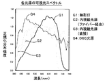
- the present invention relates to a color correction device for medical equipment, and particularly to color correction suitable for display on a color monitor for image data obtained by imaging with a medical imaging device and having a body tissue group as a subject.
- the present invention relates to a color correction device.
- Medical image display systems that capture the patient's affected area during surgery and display it on the monitor screen are used in many medical settings. For example, in the case of general open surgery, the state of the surgery can be confirmed on the monitor by using a medical image display system that takes an image of the open abdomen with a camera installed in the operating room and displays it on the monitor. can do. On the other hand, in laparoscopic surgery, it is necessary to insert an endoscopic camera into the abdominal cavity of a patient without performing a laparotomy and perform the operation while watching the image displayed on the monitor. Utilization is essential. Further, not only in the case of surgery, but also in the case of inspecting or diagnosing a sample tissue cut out from a human body, a medical image display system for imaging and displaying it on a monitor may be used.
- Patent Document 1 discloses a medical image display system that inserts an endoscope camera into a body cavity of a patient and displays an image inside the body cavity on a monitor.
- a system that supports surgery from a remote location by transmitting a captured image of a mirror camera via a public line and displaying the image on a monitor installed at a remote location is disclosed.
- a system has also been proposed in which an image captured during surgery is subjected to some image processing and displayed on a monitor.
- Patent Document 3 discloses a surgical system that performs appropriate image display on a monitor by applying image processing that matches the observation direction of a practitioner to a captured image during surgery. ..
- Patent Document 4 discloses a medical image display system capable of generating three-dimensional volume data from imaging data of an affected part of a patient undergoing surgery and displaying an intraoperative CT image on a monitor based on the three-dimensional volume data. ing.
- JP, 2005-116425 A Japanese Patent Laid-Open No. 2000-237206 JP, 2005-046200, A JP, 2011-136132, A
- cameras and monitors have unique color characteristics for each device. For example, when the same subject is photographed by a plurality of cameras in the same lighting environment, the obtained image data (usually data consisting of a set of pixels having the values of the three primary colors R, G, B) is Each is different. This is because the color characteristics of each camera are different from each other. Similarly, when the same image data is given to a plurality of color monitors for image display, the color reproducibility is different for each individual monitor. This is because the color characteristics of each color monitor are different from each other. Under such circumstances, the color reproducibility of the medical image display system provided by each provider will be different from each other. This is a great problem for the practitioner to make various diagnoses based on the image on the color monitor.
- Patent Document 3 discloses a technique of displaying an image that matches the observation direction of the practitioner on a monitor by performing image processing on the captured image
- Patent Document 4 discloses.
- a technique for generating three-dimensional volume data based on a captured image and displaying a CT image on a monitor is disclosed.
- these techniques cannot display a visible image suitable for observing a specific living tissue.
- a first object of the present invention is to eliminate the difference in color characteristics of each device and display an image with a uniform color tone even when a medical image display system is configured by combining devices having various color characteristics. Is to enable.
- a second object of the present invention is to enable a visible image display suitable for observing a specific living tissue when using the medical image display system.
- a first aspect of the present invention is a color correction device for a medical device, which performs color correction suitable for display on a color monitor with respect to image data obtained by imaging by a medical imaging device, Individual conversion data storage for imaging device that stores individual conversion data for converting the color characteristics of the imaging data by the medical imaging device into standard color characteristics in consideration of the unique color characteristics of the specific medical imaging device Department, A specific tissue emphasizing conversion data storage unit that stores specific tissue emphasizing conversion data for performing color conversion emphasizing a specific biological tissue, Storing individual conversion data for the monitor that stores individual conversion data for performing color conversion so that an image with standard color characteristics is displayed on the color monitor in consideration of the unique color characteristics of the specific color monitor Department, Image data input from a specific medical imaging device is standardized by performing color conversion using the individual conversion data for the specific medical imaging device stored in the individual conversion data storage unit for the imaging device.
- a color conversion unit for an imaging device that generates color image data An emphasized tissue designation unit that receives a designation input that designates a specific biological tissue to be highlighted, For the standard color image data, the specific tissue emphasizing conversion data for performing color conversion emphasizing the specific living tissue specified by the specified input, which is stored in the specific tissue emphasizing conversion data storage unit, is used.
- a color conversion unit for specific tissue emphasis that performs color conversion to generate specific tissue emphasized image data, The specific tissue emphasized image data is subjected to color conversion using the individual conversion data stored in the monitor individual conversion data storage unit for the specific color monitor to generate display data, and the generated display data is generated.
- a monitor color conversion unit that outputs data to the specific color monitor, Is provided.
- a second aspect of the present invention is the color correcting apparatus for a medical device according to the above-mentioned first aspect,
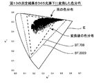
- the individual conversion data to be stored in the individual conversion data storage unit for the image pickup device use conversion data capable of color conversion that covers the wide color gamut defined by the international standard BT.2020 specifications for ultra-high definition television. It was done.
- a third aspect of the present invention is the color correcting apparatus for a medical device according to the first or second aspect described above, As the individual conversion data to be stored in the individual conversion data storage unit for the image pickup device, conversion using the color characteristics of the transmitted light of a predetermined color chart with the light from the D65 light source defined by the International Commission on Illumination as the standard color characteristics It uses data.
- a fourth aspect of the present invention is the color correction apparatus for a medical device according to the first to third aspects described above,
- the conversion data for converting the three primary color components Rold, Gold, Bold of the image pickup data into the three primary color components Rnew, Gnew, Bnew of the standard color image data are used. It is the one.
- a fifth aspect of the present invention is the color correction apparatus for a medical device according to the above-mentioned first to fourth aspects,
- the individual conversion data for a plurality of I medical imaging devices are stored in the individual conversion data storage unit for imaging device,
- the imaging device color conversion unit performs color conversion using the i-th individual conversion data on the imaging data input from the i-th (1 ⁇ i ⁇ I) medical imaging device to obtain a standard color.
- the image data is generated.
- a sixth aspect of the present invention is the color correction apparatus for a medical device according to the first to fifth aspects described above,
- the color conversion unit for an image pickup device inputs image pickup data photographed under a surgical light or an endoscope light source, and performs color conversion on the image pickup data to generate standard color image data.
- a seventh aspect of the present invention is the color correction apparatus for a medical device according to the first to sixth aspects described above,
- the individual conversion data stored in the individual conversion data storage unit for the image pickup device is configured by a look-up table that converts a combination of each color component forming the image pickup data into a combination of each color component forming the standard color image data. It was made to exist.
- An eighth aspect of the present invention is the color correction apparatus for a medical device according to the first to sixth aspects described above, A function for calculating the combination of each color component forming the standard color image data by giving the combination of each color component forming the image pickup data as a variable value to the individual conversion data stored in the individual conversion data storage unit for the image pickup apparatus. It is made up of,.
- a ninth aspect of the present invention is the color correcting apparatus for a medical device according to the first to eighth aspects described above,
- the specific tissue emphasizing conversion data for a plurality of J types of biological tissues are stored in the specific tissue emphasizing conversion data storage unit,
- the specific tissue emphasizing color conversion unit receives a designation input for designating the jth (1 ⁇ j ⁇ J) biological tissue from the emphasized tissue designating unit, the jth specific tissue emphasizing conversion data is used.
- the color conversion is performed to generate the specific tissue emphasized image data.
- a tenth aspect of the present invention is the color correcting apparatus for a medical device according to the ninth aspect described above,
- the emphasized tissue designating unit has a function of accepting designation input for designating a plurality of H kinds (H ⁇ J) of biological tissues in duplicate.
- the specific tissue emphasizing color conversion unit receives a designation input for designating a plurality of H kinds of living tissues from the emphasizing tissue specifying unit, a plurality of H kinds of specific tissue emphasizing conversion corresponding to the plurality of H kinds of living tissues.
- the specific tissue-enhanced image data is generated by performing color conversion using the data in duplicate.
- An eleventh aspect of the present invention is the color correction apparatus for a medical device according to the first to tenth aspects described above,
- the emphasized tissue designating unit has a function of accepting an empty designation input indicating that no living body tissue is designated,
- the specific organization emphasizing color conversion unit receives an empty designation input from the emphasis organization designating unit, the standard color image data is directly output as the specific organization emphasis image data without performing color conversion. ..
- a twelfth aspect of the present invention is the color correction apparatus for a medical device according to the first to eleventh aspects described above, As a specific tissue emphasizing conversion data stored in the specific tissue emphasizing conversion data storage unit, a specific color correction is performed on a color included in a localized color region specific to a specific biological tissue in a predetermined color space. It uses data.
- a thirteenth aspect of the present invention is the medical device color correcting apparatus according to the twelfth aspect described above, As the specific tissue emphasizing conversion data stored in the specific tissue emphasizing conversion data storage unit, on the predetermined two-dimensional chromaticity diagram, the abscissa is shown with respect to the color included in the localized color region peculiar to the specific biological tissue. Data for color correction that increases or decreases the value, the ordinate value, or both are used.
- a fourteenth aspect of the present invention is the color correcting apparatus for a medical device according to the thirteenth aspect described above,
- u′v′ chromaticity diagram shows u′ for a color included in a localized color region unique to a specific living tissue. The data is used to perform color correction by increasing or decreasing the value or the v'value or both of them.
- a fifteenth aspect of the present invention is the medical device color correction apparatus according to the fourteenth aspect described above,
- the emphasized tissue designating unit has a function of accepting a designation input for designating a “blood vessel” as a specific living tissue to be highlighted
- the specific tissue emphasizing conversion data storage unit includes the specific tissue emphasizing conversion data for performing color conversion emphasizing “blood vessel” in the localized color region unique to the blood vessel on the u′v′ chromaticity diagram.
- the conversion data for performing color correction for increasing the u'value is stored for the color to be displayed.
- a sixteenth aspect of the present invention is the color correction apparatus for a medical device according to the above-mentioned fourteenth or fifteenth aspect
- the emphasized tissue designating unit has a function of accepting a designation input for designating “fat” as a specific living tissue to be highlighted
- the specific tissue emphasizing conversion data storage unit includes the specific tissue emphasizing conversion data for performing the color conversion emphasizing “fat” in the localized color region unique to fat on the u′v′ chromaticity diagram.
- the conversion data for performing color correction for decreasing the u'value and increasing the v'value is stored for the color.
- a seventeenth aspect of the present invention is the color correction apparatus for a medical device according to the above fourteenth to sixteenth aspects,
- the emphasized tissue designating unit has a function of accepting a designation input for designating “surface layer” as a specific living tissue to be highlighted,
- the specific tissue emphasizing conversion data storage unit stores, as the specific tissue emphasizing conversion data for performing color conversion emphasizing the “surface layer”, a localized color region unique to the surface layer on the u′v′ chromaticity diagram.
- the conversion data for performing color correction for increasing the u'value and decreasing the v'value is stored for the color included in.
- An eighteenth aspect of the present invention is the color correction apparatus for a medical device according to the first to seventeenth aspects described above,
- the individual conversion data stored in the monitor individual conversion data storage unit use conversion data that is capable of color conversion that covers the wide color gamut defined by the international standard BT.2020 specifications for ultra-high definition TV. It is the one.
- a nineteenth aspect of the present invention provides a color correction apparatus for a medical device according to any of the first to eighteenth aspects described above,
- the monitor individual conversion data storage unit stores the individual conversion data for a plurality of K color monitors, When the monitor color conversion unit generates display data to be output to the kth (1 ⁇ k ⁇ K) color monitor, color conversion using the kth individual conversion data is performed. It is the one.
- a twentieth aspect of the present invention is the color correction apparatus for a medical device according to the first to nineteenth aspects described above,
- the individual conversion data stored in the monitor individual conversion data storage unit is configured by a look-up table that converts the combination of each color component forming the specific tissue emphasized image data into the combination of each color component forming the display data. It is something like that.
- a twenty-first aspect of the present invention is the color correction apparatus for a medical device according to the first to nineteenth aspects described above,
- the individual conversion data stored in the monitor individual conversion data storage unit calculates the combination of each color component forming the display data by giving the combination of each color component forming the specific tissue emphasized image data as a variable value. It is made up of functions.
- a twenty-second aspect of the present invention is a color correcting apparatus for a medical device, which performs color conversion for emphasizing a specific biological tissue with respect to image data having a biological tissue group as a subject,
- a specific tissue emphasizing conversion data storage unit that stores specific tissue emphasizing conversion data for performing color conversion emphasizing a specific biological tissue
- An emphasized tissue designation unit that receives a designation input that designates a specific biological tissue to be highlighted, In order to perform color conversion for emphasizing a specific biological tissue designated by a designated input, which is stored in the conversion data storage unit for specific tissue enhancement, with respect to image data obtained based on imaging by a medical imaging device
- a specific tissue emphasizing color conversion unit that performs color conversion using the specific tissue emphasizing conversion data to generate specific tissue emphasizing image data; Is provided.
- a twenty-third aspect of the present invention is the medical device color correcting apparatus according to the twenty-second aspect, As the specific tissue emphasizing conversion data stored in the specific tissue emphasizing conversion data storage unit, a specific color correction is performed on a color included in a specific localized color region specific to a specific biological tissue in a predetermined color space. The data to be used is used.
- a twenty-fourth aspect of the present invention is the medical device color correcting apparatus according to the twenty-third aspect,
- the specific tissue emphasizing conversion data to be stored in the specific tissue emphasizing conversion data storage unit the abscissa value for the color included in the localized color region specific to the specific biological tissue on the predetermined two-dimensional chromaticity diagram.
- data for color correction that increases or decreases the ordinate value or both of them is used.
- a twenty-fifth aspect of the present invention is the medical device color correction apparatus according to the twenty-fourth aspect described above,
- the u'value is set for the color included in the localized color region peculiar to the specific biological tissue on the u'v' chromaticity diagram.
- data for color correction that increases or decreases the v'value or both of them is used.
- a twenty-sixth aspect of the present invention is the medical device color correction apparatus according to the twenty-fifth aspect described above,
- the emphasized tissue designating unit has a function of accepting a designation input for designating a “blood vessel” as a specific living tissue to be highlighted,
- the specific tissue emphasizing conversion data storage unit includes the specific tissue emphasizing conversion data for performing color conversion emphasizing “blood vessel” in the localized color region unique to the blood vessel on the u′v′ chromaticity diagram.
- the conversion data for performing color correction for increasing the u'value is stored for the color to be displayed.
- a twenty-seventh aspect of the present invention is the color correction apparatus for a medical device according to the twenty-fifth or twenty-sixth aspect described above,
- the emphasized tissue designating unit has a function of accepting a designation input for designating “fat” as a specific living tissue to be highlighted,
- the specific tissue emphasizing conversion data storage unit includes the specific tissue emphasizing conversion data for performing the color conversion emphasizing “fat” in the localized color region unique to fat on the u′v′ chromaticity diagram.
- the conversion data for performing color correction for decreasing the u'value and increasing the v'value is stored for the color.
- a twenty-eighth aspect of the present invention is the color correcting apparatus for a medical device according to the twenty-fifth to twenty-seventh aspects described above,
- the emphasized tissue designating unit has a function of accepting a designation input for designating “surface layer” as a specific living tissue to be highlighted,
- the specific tissue emphasizing conversion data storage unit stores, as the specific tissue emphasizing conversion data for performing color conversion emphasizing the “surface layer”, a localized color region unique to the surface layer on the u′v′ chromaticity diagram.
- the conversion data for performing color correction for increasing the u'value and decreasing the v'value is stored for the color included in.
- a twenty-ninth aspect of the present invention provides a color correction apparatus for a medical device according to any of the first to twenty-first aspects described above, At least one medical imaging device for providing imaging data to the medical device color correction device; At least one color monitor that displays an image based on the display data output from the color correction device for a medical device; Is added to form a medical image display system.
- a thirtieth aspect of the present invention is configured by incorporating the program into a computer, the color correcting apparatus for a medical device according to the first to twenty-eighth aspects described above.
- the color correcting apparatus for a medical device is an apparatus used by being incorporated in a medical image display system including a medical imaging device and a color monitor.
- this color correction device the difference in color characteristics of individual medical imaging devices is eliminated by the color conversion unit for imaging devices, and the difference in color characteristics of individual color monitors is eliminated by the color conversion unit for monitors.
- the first object of the invention is achieved.
- standard color image data is generated by conversion by the color conversion unit for the image pickup device, and color conversion that emphasizes specific living tissue is performed on this standard color image data.
- the second object of the present invention "that enables image display with visibility suitable for observation of biological tissue” is also achieved.
- the medical device color correcting apparatus is also an apparatus used by being incorporated in a medical image display system including a medical imaging device and a color monitor.
- a medical imaging device since color conversion for emphasizing a specific living tissue is performed on image data obtained based on imaging by a medical imaging device, “visibility suitable for observing a specific living tissue”
- the second object of the present invention which enables "display of a certain image", is achieved.
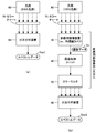
- FIG. 1 is a block diagram showing a basic configuration of a medical image display system 1000 including a medical device color correction apparatus 100 according to the present invention.
- 4 is a block diagram showing a procedure for creating individual conversion data Cx stored in an individual conversion data storage unit 110 for an imaging device shown in FIG. 3.
- FIG. 3 It is a top view which shows the specific example of the color chart 70 shown in FIG.
- FIG. 4 is a diagram showing a specific example of individual conversion data stored in an individual conversion data storage unit for imaging device 110 shown in FIG. 3 and individual conversion data stored in an individual conversion data storage unit for monitor 130.
- FIG. 8 is a u′v′ chromaticity diagram showing a color distribution obtained by performing the measurement procedure shown in FIG. 7 on the multi-color chart 72 shown in FIG. 5( b ).
- FIG. 8 is a u′v′ chromaticity diagram showing a color distribution obtained by performing the measurement procedure shown in FIG. 7 on the wide color gamut color chart 73 shown in FIG. 5C.
- the u'v' chromaticity diagram (upper row) showing the composite color distribution obtained by combining the color distribution shown in FIG. 8(b) and the color distribution shown in FIG. 9(b) and the gamut usage rate for the color distribution.
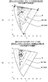
- FIG. 14 is a u′v′ chromaticity diagram showing the color distribution of each part of the large intestine specimen itself measured under an endoscope light source (via a fiber) (actually, the measurement result of FIG. That was converted to the measurement result).
- FIG. 14 is a u′v′ chromaticity diagram showing the color distribution of each part of the large intestine specimen itself measured under an endoscope light source (via a fiber) (actually, the measurement result of FIG. That was converted to the measurement result).
- FIG. 14 is a u′v′ chromaticity diagram showing a color distribution of each part of the large intestine specimen itself measured under a D65 light source (actually, the measurement result of FIG. 13 is converted into a measurement result under a D65 light source by simulation). .. It is a top view which shows the sample location of the large intestine sample and its specific tissue used for the measurement of FIG.
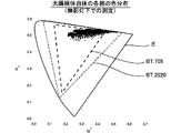
- FIG. 17 is a u′v′ chromaticity diagram showing a color distribution obtained by measuring each sample place shown in FIG. 16 under an operating light.
- FIG. 17 is a u′v′ chromaticity diagram showing a color distribution obtained by measuring each sample portion shown in FIG. 16 under a D65 light source.
- FIG. 4 is a front view showing an example of an instruction button forming an emphasized tissue designating section 150 in the medical device color correction apparatus 100 shown in FIG. 3.
- 10 is a u′v′ chromaticity diagram showing a color distribution of image data obtained by performing various enhancement corrections by the specific tissue enhancement color conversion unit 160 on the image data having the color distribution shown in FIG. is there.
- FIG. 1 is a block diagram showing a state of an operating room in which a conventional general medical image display system is introduced.
- an operating table 10 is installed in the operating room, and a subject (patient) P is lying thereon.
- a surgical light 20 is installed above the operating table 10 to illuminate the affected part of the subject P.
- the illustrated example is an example in which a laparoscopic surgery is performed on the subject P. During the surgery, an opening with a diameter of about 10 mm is formed in the abdomen of the subject P, and the distal end of the endoscope camera 31. The part is inserted into the abdominal cavity of the subject P.
- the endoscope camera 31 is connected to the endoscope control unit 41 by a cable.
- the endoscopic control unit 41 is a device for controlling the endoscopic camera 31, and supplies power to the endoscopic camera 31, captures imaging data from the endoscopic camera 31, and attaches to the endoscopic camera 31. It has a function of turning on/off the existing endoscope light source and recording image data. Although only one endoscopic camera 31 is shown in the drawing, a plurality of endoscopic cameras may be used as needed.
- color monitors 51 to 54 are connected to the endoscope control unit 41, and the image captured by the endoscope camera 31 is displayed in each color via the endoscope control unit 41. It is sent to the monitors 51 to 54 and displayed on each screen. The practitioner performs laparoscopic surgery while looking at the image on the screen (illustration of surgical instruments is omitted).
- the color monitors 51 to 54 do not necessarily have to be installed in the operating room, and some or all of them may be installed in another room (for example, a conference room).
- a monitor is arranged at a remote place, and surgery is performed by remote control.
- the system including the endoscope camera 31, the endoscope control unit 41, and the color monitors 51 to 54 constitutes a medical image display system.
- a medical image display system is introduced as necessary.
- a normal camera that images the affected area from above is usually used instead of the endoscope camera 31, but in a special laparotomy, an endoscope camera may be used together.
- the practitioner usually performs the operation while observing the affected area with the naked eye, so the display image on the monitor is used as information to be presented to the practitioner assistant and other related persons.
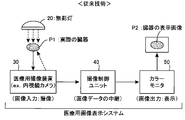
- FIG. 2 is a block diagram showing the flow of image data in a conventional general medical image display system.
- an image of an actual organ P1 which is an affected part of the subject P is imaged by the medical imaging device 30, and the obtained imaging data is transmitted to the color monitor 50 via the imaging control unit 40.
- An example in which the display image P2 of the organ is displayed on the screen is shown.
- the endoscope camera 31 is used as the medical imaging device 30, and the endoscope control unit 41 is used as the imaging control unit 40.
- a surgical light 20 is arranged above the subject P, and the subject P is illuminated by light from the surgical light 20 (in FIG. 2, the surgical light 20 is actually used).
- the dashed arrow pointing to the organ P1 indicates such illumination light.
- the illumination light from the surgical light 20 does not reach the actual organ P1 that is the subject, so the endoscope light source attached to the endoscope camera (the light source with the endoscope camera) ) (In FIG. 2, the dashed arrow pointing from the medical imaging device 30 to the actual organ P1 indicates the illumination light from the endoscope light source).
- the system including the medical imaging device 30, the imaging control unit 40, and the color monitor 50 constitutes a medical image display system.
- the medical imaging device 30 is a component that inputs an image by capturing an image of an actual organ P1
- the imaging control unit 40 performs a process of relaying image data obtained by this image input.
- the color monitor 50 is an element that is an element that outputs an image by displaying the display image P2 of the organ on the screen based on the given image data.
- the medical imaging device 30 and the color monitor 50 have unique color characteristics for each device. Therefore, between the color tone of the display image P2 of the organ normally displayed on the screen of the color monitor 50 and the color tone of the actual organ P1 (the color tone under the illumination of the surgical light 20 or the endoscope light source). There will be a difference. Moreover, this difference in color tone differs depending on the device actually used as the medical imaging device 30 and the device actually used as the color monitor 50. Therefore, when a plurality of types of cameras are used as the medical imaging apparatus 30 or a plurality of types of devices are used as the color monitor 50, a specific mode of which color monitor displays an image captured by which camera is used. As a result, the color tone of the display image P2 of the organ changes.
- a first object of the present invention is to eliminate the difference in color characteristics between devices even when a medical image display system is configured by combining devices having various color characteristics. It is to enable image display with a uniform color tone.
- a second object of the present invention is to enable a visible image display suitable for observing a specific living tissue.
- Medical image display system according to the present invention >>>
- a basic configuration and a basic function of the medical image display system according to the present invention and the color correcting apparatus for a medical device incorporated and used in the system will be described.
- FIG. 3 is a block diagram showing the basic configuration of a medical image display system 1000 including the medical device color correction apparatus 100 according to the present invention.
- the medical image display system 1000 illustrated here includes three medical imaging devices 30X to 30Z, four color monitors 50A to 50D, and one medical device color correction device 100.
- the medical imaging devices 30X to 30Z correspond to the medical imaging device 30 and the color monitors 50A to 50D.
- the medical device color correction apparatus 100 corresponds to the imaging control unit 40.
- the device 100 performs predetermined color correction processing on the image data Dx to Dz obtained from the medical image pickup devices 30X to 30Z to create display data Da to Dd suitable for the color monitors 50A to 50D. It has a function.
- the medical imaging devices 30X to 30Z may be any devices as long as they are devices that capture medical images. Specifically, for example, it may be an endoscopic camera used for laparoscopic surgery or a normal video camera arranged in an operating room. Of course, the image data obtained by the imaging by the medical imaging devices 30X to 30Z may be still image data or moving image data. Further, the medical image display system 1000 shown here is not limited to the use for surgery, but is also used for the purpose of taking an image of a sample tissue cut out from a human body and displaying it on a color monitor for inspection or diagnosis. It is possible, and when used for such an application, for example, a microscope camera can be used as a medical imaging device.
- the color monitors 50A to 50D may be any device as long as it has a color image display function.
- a color display connected to a computer may be used as the color monitors 50A to 50D.
- the installation locations of the color monitors 50A to 50D are also arbitrary.
- the medical image display system 1000 is configured by connecting the three medical imaging devices 30X to 30Z and the four color monitors 50A to 50D to the medical device color correction device 100.
- the number of medical imaging devices and the number of color monitors may be arbitrary. In order to configure the medical image display system 1000 according to the present invention, it is sufficient to connect at least one medical imaging device 30 and at least one color monitor 50 to the medical device color correction device 100.
- the medical device color correction apparatus 100 shown in FIG. 3 has an imaging device individual conversion data storage unit 110, a specific tissue emphasizing conversion data storage unit 120, and a monitor individual conversion data storage unit, as indicated by the one-dot chain line in the figure.
- the unit 130, the imaging device color conversion unit 140, the emphasized tissue designation unit 150, the specific tissue emphasis color conversion unit 160, and the monitor color conversion unit 170 are included.
- each of these components can be realized by incorporating a dedicated program into a computer. Therefore, in practice, the medical device color correction apparatus 100 shown in FIG. 3 is configured by a computer incorporating a dedicated program, and the medical imaging devices 30X to 30Z and the color monitors 50A to 50D are connected to this computer. It will be. Note that in FIG. 3, each component is drawn as a rectangular block, and digital data transmitted and received between the rectangular blocks is drawn as an elliptical block.
- the color correcting apparatus 100 for a medical device processes image data (actually, a plurality of image data arranged in time series to form a moving image) obtained by imaging by the medical imaging apparatuses 30X to 30Z. , And has a function of performing color correction suitable for display on the color monitors 50A to 50D.
- image data image data input to the medical device color correction apparatus 100
- imaging data Dx, Dy, and Dz image data obtained by imaging by the medical imaging apparatuses 30X to 30Z
- Image data provided to the color monitors 50A to 50D image data output from the medical device color correction apparatus 100
- display data Da, Db, Dc, and Dd respectively. Therefore, the medical-apparatus color correction apparatus 100 performs predetermined color correction processing on the input image pickup data Dx, Dy, Dz, and sets the processed image data as display data Da, Db, Dc, Dd. It plays the role of outputting.
- the first conversion process is a process performed on the input imaging data Dx, Dy, Dz, and uses the individual conversion data Cx, Cy, Cz stored in the imaging device individual conversion data storage unit 110. Then, it is executed by the color conversion unit 140 for the imaging device.
- the purpose of this first conversion process is to eliminate the difference in color characteristics of the medical imaging devices 30X, 30Y, and 30Z for each device, and the standard color image output from the imaging device color conversion unit 140.
- the data Ds is image data having a tint of a standard color that eliminates the difference in color characteristics between devices.
- the subsequent second conversion process is a process performed on the standard color image data Ds output from the imaging device color conversion unit 140, and is stored in the specific tissue emphasis conversion data storage unit 120.
- the specific tissue emphasizing conversion data (in the illustrated example, blood vessel emphasizing data Ce, fat emphasizing data Cf, surface layer emphasizing data Cg) is used by the specific tissue emphasizing color conversion unit 160.
- the purpose of the second conversion processing is to perform color conversion that emphasizes the specific living tissue in order to display an image with visibility suitable for observing the specific living tissue designated by the operator.
- the specific tissue emphasized image data (data De, Df, Dg are shown in the figure according to the specified biological tissue) output from the specific tissue emphasis color conversion unit 160 is the observation of the specific biological tissue.
- the image data corresponds to an image with visibility suitable for.
- the third conversion process performed last is a process performed on the specific tissue emphasized image data De, Df, and Dg output from the specific tissue emphasis color conversion unit 160, and the monitor individual conversion data storage unit 130.
- the color conversion unit for monitor 170 uses the individual conversion data Ca, Cb, Cc, and Cd stored in.
- the purpose of the third conversion process is to eliminate the difference in color characteristics between the devices of the color monitors 50A to 50D, and to display each of the display data Da, Db, output from the monitor color conversion unit 170.
- Dc and Dd are image data that have been corrected to eliminate the difference in color characteristics between individual devices.
- each arrow pointing downward does not show the flow of individual image data itself, but shows the flow of the conversion process regarding the hue.
- the three sets of image pickup data Dx, Dy, Dz on the side have unique hues
- the standard color image data Ds on the output side has a common standard color.
- the three downward arrows on the input stage have different imaging data Dx, Dy, and Dz due to the unique color characteristics of the respective imaging devices even when the same subject is imaged under the same conditions.
- the specific tissue emphasizing color conversion unit 160 converts the hue of the standard color image data Ds in accordance with the specific living tissue to be emphasized, so that the specific tissue emphasizing image data (image data De, Df, Dg Or) is output. Therefore, the specific organization emphasized image data drawn as one downward arrow is given to the input stage of the monitor color conversion section 170.
- the four downward arrows are drawn on the output stage of the monitor color conversion unit 170 because the shades of the display data Da to Dd given to the individual color monitors 50A to 50D are different from those of the individual color monitors 50A to 50D. It is shown that it differs depending on the inherent color characteristics that it has. That is, even if the same specific tissue emphasized image data is given to the input stage of the monitor color conversion section 170, different display data Da to Dd are obtained at the output stage.
- the imaging device individual conversion data storage unit 110 converts the color characteristics of the imaging data of the medical imaging device into standard color characteristics in consideration of the unique color characteristics of a specific medical imaging device. It is a component that stores individual conversion data.
- the imaging device individual conversion data storage unit 110 is Individual conversion data Cx, Cy, Cz are prepared corresponding to these three medical imaging devices 30X, 30Y, 30Z, respectively.
- the individual conversion data Cx is conversion data for converting the color characteristics of the imaging data Dx captured by the medical imaging apparatus 30X into standard color characteristics in consideration of the unique color characteristics of the medical imaging apparatus 30X. The substance of such conversion data will be described in detail in ⁇ 3.
- the imaging device color conversion unit 140 performs individual conversion on the specific medical imaging device stored in the imaging device individual conversion data storage unit 110 with respect to the imaging data input from the specific medical imaging device. It is a component that generates standard color image data by performing color conversion using data. For example, when the imaging data Dx is given from the medical imaging device 30X, the imaging device color conversion unit 140 stores the imaging data Dx in the imaging device individual conversion data storage unit 110. The processing for generating the standard color image data Ds by performing color conversion using the individual conversion data Cx for the image capturing device 30X is executed.
- the imaging device individual conversion data storage unit 110 includes three sets of individual devices. Although conversion data Cx, Cy, Cz are prepared, in general, if the use of a plurality of I medical imaging devices is assumed, the I conversion data storage unit 110 for each of these I medical imaging devices is used. It is only necessary to store the individual conversion data for each image pickup device.
- the imaging device color conversion unit 140 for the imaging data Di input from the i-th (1 ⁇ i ⁇ I) medical imaging device 30i, converts the i-th individual conversion data Ci (i-th). The color conversion is performed using the individual conversion data of the th medical imaging device 30i) to generate the standard color image data Ds.
- the standard color image data Ds obtained by the color conversion processing by the image-capturing device color conversion unit 140 is obtained by converting the color characteristics unique to each medical imaging device into the standard color characteristics.
- the image data has a uniform color tone by eliminating the difference in the color characteristics of. Therefore, when the same subject is photographed by the three medical image pickup devices 30X, 30Y, 30Z under the same image pickup condition, the contents of the obtained image pickup data Dx, Dy, Dz are different from each other.
- the three types of standard color image data (herein referred to as Dsx, Dsy, Dsz) obtained by the color conversion processing on the image pickup data Dx, Dy, Dz are theoretically the same image data.
- the hues of the images represented by the individual image pickup data Dx, Dy, and Dz differ from each other according to the color characteristics unique to each image pickup device.
- the hues of the images represented by the standard color image data Dsx, Dsy, and Dsz obtained after the conversion are theoretically the same.
- One of the important features of the color correcting apparatus 100 for medical equipment shown in FIG. 3 is the imaging data Dx obtained from each of the medical imaging apparatuses 30X, 30Y, 30Z by the color conversion processing by the color conversion unit for imaging apparatus 140.
- Dy, Dz are once converted into standard color image data Ds (first conversion processing), and the color conversion processing by the specific tissue emphasizing color conversion section 160 is performed on the standard color image data Ds,
- the specific tissue emphasized image data De, Df, Dg in which the specific biological tissue is emphasized is generated (second conversion processing), and the color conversion processing by the monitor color conversion section 170 is further performed on it. This is at the point of generating the display data Da to Dd corresponding to the color monitors 50A to 50D (third conversion processing).
- each medical treatment is performed when performing color conversion processing by the specific tissue emphasizing color conversion unit 160. It is not necessary to consider the color characteristics peculiar to the image pickup devices 30X, 30Y, 30Z.
- the specific tissue emphasizing conversion data storage unit 120 stores the specific tissue emphasizing conversion data for performing color conversion for emphasizing a specific biological tissue with respect to the standard color image data Ds having a standard hue. Just keep it.
- the specific organization emphasizing conversion data storage unit 120 stores three types of specific organization emphasizing conversion data. Specifically, the blood vessel emphasis data Ce for performing color conversion for emphasizing blood vessels, the fat emphasis data Cf for performing color conversion for emphasizing fat, and the surface layer film (film forming a surface layer of an organ or the like) are emphasized.
- the three types of specific tissue emphasizing conversion data that is, surface layer emphasizing data Cg for performing color conversion, are stored. Specific examples of the specific tissue emphasizing conversion data Ce, Cf, Cg, and an example of “emphasized display” of specific biological tissue will be described in detail in ⁇ 6.
- the emphasized organization designating unit 150 is a component that receives a designation input that designates a specific biological tissue to be highlighted. This designation input is performed by an operator of the medical device color correction apparatus 100 (for example, a practitioner during surgery). The operator makes an input for designating the living tissue to be highlighted on the images displayed on the color monitors 50A to 50D. In short, the operator wants to display an image with improved visibility of which living tissue, in other words, which living tissue to display an image suitable for observation, Specify the organization.
- the emphasized tissue designating unit 150 plays a role of transmitting a designation input from the operator to the specific tissue enhancing color conversion unit 160.
- the specific tissue emphasizing color conversion unit 160 performs color conversion on the standard color image data Ds, which is stored in the specific tissue emphasizing conversion data storage unit 120 and emphasizes a specific biological tissue designated by a designation input. Color conversion is performed using the specific tissue emphasizing conversion data for performing the specific tissue emphasizing image data. For example, if the operator inputs “blood vessel” as the specific biological tissue to be highlighted, the highlighted tissue designation unit 150 instructs the specific tissue highlighting color conversion unit 160 to highlight the target. Is transmitted as "blood vessel”. Therefore, the specific tissue emphasizing color conversion unit 160 selects the blood vessel emphasizing data Ce from the three sets of the specific tissue emphasizing conversion data stored in the specific tissue emphasizing conversion data storage unit 120, and selects the blood vessel emphasizing data Ce.
- the Ce is used to perform the color conversion process on the standard color image data Ds, and the specific tissue emphasized image data De of the blood vessel is output as the processed image data.
- the specific tissue emphasized image data Df for fat is subjected to color conversion processing using the fat emphasis data Cf or the surface layer emphasis data Cg.
- the specific tissue emphasized image data Dg of the surface layer film is output.
- tissue enhancement conversion data for a plurality of J types of biological tissues are stored in the specific tissue enhancement conversion data storage unit 120, respectively.
- the tissue-enhancing color conversion unit 160 receives a designation input for designating the j-th (1 ⁇ j ⁇ J) biological tissue from the emphasized-tissue designating unit 150, the j-th specific tissue-enhancing conversion data Cj Color conversion using (conversion data for emphasizing the j-th biological tissue) may be performed to generate specific tissue emphasized image data.
- the designation input to the emphasized tissue designation unit 150 does not necessarily have to be an input that designates a single living tissue, and may be an input that designates a plurality of living tissues. For example, if the operator wants to highlight both “blood vessel” and “fat”, he/she may input to the emphasized tissue designating section 150 to designate both of them. In this case, the fact that both “blood vessel” and “fat” have been designated is transmitted from the emphasized tissue designating unit 150 to the specific tissue enhancing color converting unit 160, so that the specific tissue enhancing color converting unit 160 , The standard color image data Ds is overlapped with the color conversion using the blood vessel emphasis data Ce and the color conversion using the fat emphasis data Cf, and the specific tissue emphasis image data Def is output. The display on the color monitor using the specific tissue emphasized image data Def is a display in which both “blood vessel” and “fat” are emphasized.
- the emphasized tissue designating unit 150 has a function of accepting a designation input for designating a plurality of H (H ⁇ J) biological tissues in duplicate. It is provided (J is the total number of the specific organization emphasizing conversion data stored in the specific organization emphasizing conversion data storage section 120 ), and the specific organization emphasizing color converting section 160 has a plurality of H types from the emphasizing organization designating section 150.
- the specific tissue-enhanced image data is obtained by performing the color conversion using the plurality of H types of the specific-tissue-enhancing conversion data corresponding to the plurality of H types of the biological tissues in duplicate. Should be generated.
- the emphasized organization designating section 150 can also accept a designation input “hereinafter, no body tissue is designated” (hereinafter referred to as “empty designation input”).
- the specific tissue emphasizing color conversion unit 160 outputs the input standard color image data Ds as it is without performing any substantial color conversion processing.
- the standard color image data Ds is output as it is as the specific tissue emphasized image data Ds.
- the display on the color monitor using the specific tissue emphasized image data Ds is an image in which neither living body tissue is emphasized.
- the emphasized tissue designating unit 150 has a function of accepting an empty designation input indicating that no living body tissue is designated, and the specific tissue enhancing color conversion unit 160 uses the emphasized tissue designation.
- the standard color image data Ds is directly output as the specific tissue emphasized image data without performing color conversion.
- the specific tissue enhancing conversion data storage unit 120 stores It is sufficient to store only the blood vessel emphasis data Ce.
- the specific tissue emphasizing color conversion unit 160 performs the color conversion, the color conversion using the blood vessel emphasizing data Ce is always performed, and the specific tissue emphasizing image data De is always output.
- the emphasized organization designating section 150 can be provided with a function of accepting an empty designation input. Then, the designation input to the emphasized tissue designation unit 150 is an input for selecting whether to perform highlighting (input to specify a blood vessel) or not to perform highlighting (empty designation input). ..
- the emphasized tissue designating unit 150 is provided with a function of accepting different designation inputs for the individual color monitors 50A to 50D, different living tissues are highlighted for the individual color monitors 50A to 50D. Images can be displayed. For example, with respect to the emphasized tissue designating unit 150, an empty designation input for the color monitor 50A, a "blood vessel” designation input for the color monitor 50B, a “fat” designation input for the color monitor 50C, and a “fat” designation input for the color monitor 50D.
- the specific tissue emphasizing color conversion unit 160 may output four types of specific tissue emphasizing image data Ds, De, Df, Dg.
- the monitor color converter 170 performs color conversion using the individual conversion data Ca on the image data Ds to generate display data Da, and uses the individual conversion data Cb on the image data De. Color conversion is performed to generate display data Db, image data Df is subjected to color conversion using individual conversion data Cc to generate display data Dc, and image data Dg is converted to individual conversion data Cd.
- the display data Dd may be generated by performing the color conversion used. Then, the standard color image is displayed on the color monitor 50A, the image in which "blood vessel” is emphasized is displayed in the color monitor 50B, and the image in which "fat” is emphasized is displayed on the color monitor 50C. Then, the image in which the “surface layer” is emphasized is displayed on the color monitor 50D.
- the monitor individual conversion data storage unit 130 is a component that stores the individual conversion data Ca to Cd corresponding to each of the color monitors 50A to 50D.
- These individual conversion data Ca to Cd are designed so that images having standard color characteristics are displayed on the color monitors 50A to 50D in consideration of the unique color characteristics of the corresponding specific color monitors 50A to 50D. This is conversion data for performing various color conversions.
- the monitor color conversion unit 170 for the specific tissue emphasized image data provided from the specific tissue emphasis color conversion unit 160, regarding the specific color monitor stored in the monitor individual conversion data storage unit 130. Is a constituent element that performs color conversion using the individual conversion data to generate display data, and outputs the generated display data to the specific color monitor.
- the specific tissue emphasis image data De for emphasizing the “blood vessel” is given to the monitor color conversion unit 170 from the specific tissue emphasis color conversion unit 160, and an image based on this image data De is converted into a first color image.
- the individual conversion data Ca for the first color monitor 50A stored in the monitor individual conversion data storage unit 130 is used for the specific tissue emphasized image data De. The color conversion is performed to generate the display data Da, and the generated display data Da is output to the first color monitor 50A.
- the individual conversion data Cx to Cz stored in the individual conversion data storage unit 110 for the imaging device are converted to eliminate the difference in the unique color characteristics of the medical imaging devices 30X to 30Z.
- the image capturing device color conversion unit 140 performs a process of generating standard color image data Ds in which such a difference in unique color characteristics is resolved.
- the individual conversion data Ca to Cd stored in the monitor individual conversion data storage unit 130 are data for performing conversion for eliminating the difference in the unique color characteristics of the color monitors 50A to 50D. Therefore, the monitor color conversion section 170 eliminates such a difference in the unique color characteristics and enables the individual color monitors 50A to 50D to display with the same color tone on the screen of any color monitor. Processing for generating display data Da to Dd suitable for
- the monitor individual conversion data storage unit 130 stores the individual conversion data for each of the K medical imaging devices. Just keep it.
- the monitor color conversion unit 170 when the monitor color conversion unit 170 generates the display data Dk to be output to the kth (1 ⁇ k ⁇ K) color monitor 50k, the kth individual conversion data Ck( Color conversion may be performed using (individual conversion data for the kth color monitor 50k).
- the individual images are displayed on the screens of the individual color monitors in the same color tone.
- the technique itself for performing color conversion on image data using the individual conversion data prepared for each color monitor is already known.
- individual conversion data generally called color profile data
- the color profile data may be used as the individual conversion data stored in the monitor individual conversion data storage unit 130.
- the method of creating the color profile data unique to each color monitor is also a known method, and a detailed description thereof will be omitted here.
- the first conversion process by the imaging device color conversion unit 140 the second conversion process by the specific tissue enhancing color conversion unit 160, and the monitor process.
- a three-stage color conversion process of the third conversion process by the color conversion unit 170 is performed.
- the first conversion process and the third conversion process play a role of eliminating the difference in color characteristics between devices, and by these processes, "a device having various color characteristics is combined to form a medical image display system. Even when configured, the first object of the present invention is achieved, which eliminates the difference in color characteristics of each device and enables image display with a uniform color tone.
- the second conversion process plays a role of highlighting a specific living tissue specified by the operator, and by this processing, “when using the medical image display system, it is suitable for observing a specific living tissue”.
- the second object of the present invention "to enable visible image display” is achieved. For example, as will be described in detail later, if the operator designates a specific living tissue such as “blood vessel”, “fat”, or “surface membrane” as an object to be highlighted, the visibility of the designated living tissue is improved. Improved display will be obtained. For example, in the conventional system, the color of blood, which is saturated in the imaging stage, can be accurately read on the color monitor.
- the second conversion process since the second conversion process is performed between the first conversion process and the third conversion process, it can be executed as a process for the standard color image data Ds obtained by the first conversion process. it can. Therefore, when performing the second conversion processing, it is not necessary to consider the “color characteristic unique to the device”, which is the color characteristic of each medical imaging device, and the standard color image data having the standard color characteristic is always used. It suffices to perform uniform color correction with Ds as the processing target.
- the third conversion process since the third conversion process is performed after the second conversion process, when performing the second conversion process, the color characteristic of the color monitor that is finally displayed as an image is a “device specific”. It is not necessary to consider "color characteristics". In other words, regardless of the model of the medical imaging device or the color monitor that is actually used, the specific organization emphasizing conversion data storage unit 120 should always have uniform specific organization emphasizing conversion data. Is enough.
- the color correcting apparatus 100 for a medical device according to the present invention is a color monitor connected to the output side regardless of which model is provided by which manufacturer the medical imaging apparatus connected to the input side is.
- any model provided by any manufacturer can be used without considering the difference in color characteristics between models. Therefore, it is possible to perform color judgment based on the same standard regardless of which hospital or research facility as long as the facility has introduced the medical image display system 1000 according to the present invention. Become.
- image data handled by an image pickup device or a color monitor device is composed of a set of many pixels.
- Each pixel usually has pixel values of the three primary color components R, G, B.
- R, G, B For example, if one color component is represented by 8-bit data, the pixel value of one pixel is represented by 24-bit data. Therefore, the pixel values of the individual pixels forming the imaging data Dx obtained from the medical imaging device 30X are represented by the three primary color components Rold, Gold, Bold, and the standard color image obtained by color conversion by the imaging device color conversion unit 140.
- the individual conversion data Cx stored in the individual conversion data storage unit 110 for the image pickup device is the three primary color components of the imaging data Dx.
- This is conversion data for converting Rold, Gold, Bold into the three primary color components Rnew, Gnew, Bnew of the standard color image data Ds. That is, it is possible to use, as the individual conversion data Cx, some information that can uniquely obtain another value (Rnew, Gnew, Bnew) based on an arbitrary value (Rold, Gold, Bold).
- a white light source 60 and a color chart 70 are prepared.
- a light source compliant with the CIE standard light source D65 (hereinafter, simply referred to as “D65 light source”) is used.
- This D65 light source is a standard light source defined by the International Commission on Illumination (CIE), is a virtual light source having a spectrum corresponding to the average noon light in Europe/North Europe, and has a correlated color temperature of about 6500K. Has been done.
- CIE International Commission on Illumination
- the standard light source itself which is the “D65 light source”
- D65 light source is not actually commercially available as a device
- a commercially available device for example, an LED light source
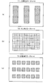
- the color chart 70 is a plate-shaped object in which color samples are arranged, and is used for purposes such as checking color reproducibility and color calibration for various image devices. Plan views of some specific examples of the color chart 70 are shown in FIGS. 5(a), (b), and (c).
- the three primary color chart 71 shown in FIG. 5(a) is the simplest color chart in which color samples of the three primary colors of red, blue, and green are arranged.
- the three regions shown by hatching in the figure are the portions of the color samples of the three primary colors, each of which has translucency for transmitting red, blue, and green color components. Therefore, when the white light source 60 is arranged on the back surface and the three primary color chart 71 is observed from the front, each area is observed as a window of red, blue, and green.
- the multi-color chart 72 shown in FIG. 5(b) is one in which a large number of square color samples are arranged in a two-dimensional array. Normally, the color reproducibility of a camera or monitor in low to medium saturation is reproducible. Is used to verify. In the three primary color chart 71 shown in FIG. 5(a), only the color samples of the three primary colors of red, blue, and green are arranged, while in the multi-color chart 72 shown in FIG. 5(b), there are 153 The color swatches of are laid out so that finer color calibration can be performed. On the other hand, in the wide color gamut color chart 73 shown in FIG.
- the wide color gamut defined by the international standard BT.2020 for ultra-high definition TV is specified. It is a color sample that covers the area.
- the wide color gamut color chart 73 is suitable for verifying the color reproducibility of highly saturated colors and primary colors, and a specific color calibration method using this will be described in ⁇ 4.
- FIG. 5 illustrates three types of color charts 71, 72, 73, of course, various products are commercially available as the color chart, and the color chart used in the present invention is shown in FIG. It is not limited to three types.
- a color chart generally called a Macbeth chart may be used to supplement the medium saturation color.
- the light source 60 is arranged on the back surface of the color chart 70
- the medical imaging device 30X for example, an endoscope camera
- An image is taken by the medical imaging device 30X.
- the transmitted light in each color sample area of the color chart 70 is incident on the light receiving surface of the medical imaging device 30X.
- the dashed arrow shown in FIG. 4 indicates the path of light from the light source 60.
- the color components of the three primary colors (R, G, B) for the individual color sample areas of the color chart 70 will be referred to as image color data Dt (Rt, Gt, Bt). ..
- the image pickup color data Dt1 (Rt1, Gt1, Bt1) for the red area and the image pickup color data Dt2 (Rt2 for the green area) are used.
- Gt2, Bt2) and imaging color data Dt3 (Rt3, Gt3, Bt3) for the red region are obtained.
- the multi-color chart 72 shown in FIG. 5B is used as the color chart 70, the captured color data Dt1 (Rt1, Gt1, Bt1) to the 153rd color for the first color sample Imaging color data Dt153 (Rt153, Gt153, Bt153) for the sample will be obtained.
- the original color data DT (RT, GT, BT) of each color sample of the color chart 70 is measured.
- the dashed-dotted arrow in FIG. 4 indicates that the color data DT can be obtained by using such a measurement process.
- the original color data DT1 (RT1, GT1, BT1) for the red area and the original color data DT2 for the green area are used.
- RT2, GT2, BT2 the original color data DT3 (RT3, GT3, BT3) for the blue area are obtained.
- the multi-color chart 72 shown in FIG. 5B is used as the color chart 70
- the original color data DT153 (RT153, GT153, BT153) for the color sample is obtained.
- the original color data DT is measured, for example, by disposing a spectroscopic analyzer (colorimeter) at the position of the medical imaging device 30X shown in FIG. 4 and measuring the spectrum for each of the regions of each color sample (The measurement system similar to the measurement system shown in FIG. 7(a) described later may be used), and the values of the three primary color components (RT, GT, BT) may be calculated based on the data of this spectrum.
- the commercially available color chart 70 has the original color data DT (RT, GT, BT) obtained by the measurement at the supplier attached, and in such a case, the measurement work is omitted. Then, the attached original color data DT (RT, GT, BT) may be used as it is.
- the individual conversion data creation unit 80 is actually a device that is configured by incorporating a dedicated program into a computer, and the captured color data Dt (Rt, Gt, Bt) for each color sample and the original color data DT (RT , GT, BT) based on the difference between the color characteristics unique to the medical imaging device 30X and the imaging color data Dt (Rt, Gt, Bt) as the original color data DT (RT, GT, BT).
- the data Dt (Rt, Gt, Bt) and the data DT (RT, GT, BT) are compared for each of the three color samples based on the result. Since it is necessary to create the individual conversion data Cx (data that enables conversion for an arbitrary color), the accuracy of the obtained individual conversion data Cx becomes relatively coarse.
- the data Dt (Rt, Gt, Bt) and the data DT (RT, GT, BT) for 153 color samples are respectively obtained. Since the individual conversion data Cx can be created based on the comparison result, the individual conversion data Cx with higher accuracy can be obtained.
- the individual conversion data Cx includes the three primary color components Rold, Gold, and Bold of the individual pixels forming the image pickup data Dx obtained by the medical image pickup apparatus 30X and the individual pixels forming the standard color image data Ds.
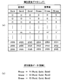
- Such individual conversion data Cx can be prepared, for example, in the form of a lookup table LUT as shown in FIG.
- the left half of the table of FIG. 6(a) shows the three primary color components Rold, Gold, Bold of the individual pixels that make up the image data before conversion (imaging data Dx), and the right half shows the image data after conversion.
- each color component is represented by a numerical value of 8 bits (0 to 255).
- the left half of the table from (0,0,0) to (255,255,255), 256 ⁇ 256.
- the individual conversion data composed of the lookup table LUT when a combination (l, m, n) of arbitrary pixel values indicating the three primary color components is given, this is combined with a predetermined pixel value combination (l' , M', n').
- the combination of the color components of the pixels forming the image pickup data Dx is set to the color components of the pixels forming the standard color image data Ds.
- the individual conversion data Cx can also be prepared in the form of a function as shown in FIG. 6(b).
- a function for calculating the combination of the color components of the pixels forming the standard color image data Ds is prepared by giving the combination of the color components of the pixels forming the image pickup data Dx as a variable value. It may be stored as individual conversion data Cx in the device individual conversion data storage unit 110.
- the form of the lookup table LUT shown in FIG. 6(a) and the form of the function shown in FIG. 6(b) have been illustrated as the substance of the individual converted data stored in the individual converted data storage unit 110 for the imaging device.
- the same form can be adopted for the individual conversion data stored in the monitor individual conversion data storage unit 130. That is, as the individual conversion data (for example, data Ca) stored in the monitor individual conversion data storage unit 130, a combination of each color component of the pixels forming the specific tissue emphasized image data (for example, data De) is displayed.
- a lookup table for converting into a combination of color components of pixels forming data for example, data Da
- a combination of color components of pixels forming specific tissue emphasized image data for example, data De
- a function for calculating the combination of the respective color components of the pixels forming the display data for example, the data Da
- FIG. 7 is a diagram showing a basic procedure of measurement for examining color reproducibility on a color monitor in a medical image display system (a broken line in the figure indicates a light path).
- a color chart 70 in which a plurality of color samples are arranged is used.
- the first procedure shown in FIG. 7A the original color of each color sample of this color chart 70 is measured.
- the second procedure shown in FIG. 7B each color sample of the color chart 70 is imaged by the medical image display system and displayed on the color monitor, and the color displayed on the color monitor is measured.
- the measurement is performed by the following method.
- the light source 60 is arranged on the back surface of the color chart 70, the spectroscopic analysis device 90 is arranged on the front surface of the color chart 70, and the light source 60 is arranged on the color chart 70.
- the spectrum of the transmitted light from each color sample is measured to obtain spectrum data Dsp1.
- spectrum data Dsp1 of transmitted light is obtained for all 153 sets of color samples.
- the light source 60 is arranged on the back side of the color chart 70, and the medical imaging device 30 (for example, an endoscope camera) is placed on the front side of the color chart 70.
- the color chart 70 is arranged and imaged to obtain the imaged data Dp.
- This image pickup data Dp is given to the color monitor 50 via the image pickup control unit 40, and the imaged color chart 70 is displayed on the screen of the color monitor 50.
- the medical imaging device 30, the imaging control unit 40, and the color monitor 50 are components of the medical image display system as shown in FIG.
- the spectral analyzer 90 is arranged in front of the color monitor 50, and the spectrum of each color sample of the color chart 70 displayed on the color monitor 50 is measured to obtain spectrum data Dsp2.
- spectrum data Dsp2 of the transmitted light is obtained for all 153 sets of color samples.
- the same D65 light source is used as the light source 60 used in FIGS. 7A and 7B, and the same multi-color chart 72 is used as the color chart 70. Therefore, the first procedure shown in FIG. 7(a) and the second procedure shown in FIG. 7(b) illuminate the same subject (multi-color chart 72) in the same illumination environment (D65 light source).
- the spectrum data Dsp1 obtained in the former is a spectrum obtained by directly measuring the transmitted light of the color sample
- the spectrum data Dsp2 obtained in the latter is a spectrum image for a medical image display system ( This is a spectrum obtained when observed through the medical imaging device 30, the imaging control unit 40, and the color monitor 50).
- the measurement is performed with the endoscope light source built in this endoscope camera in the OFF state. That is, in the second procedure shown in FIG. 7B, the light source for illuminating the color chart 70 is only the light source 60 (D65 light source).
- the color reproducibility when observed through the medical image display system can be evaluated.
- a two-dimensional chromaticity diagram is used.
- FIG. 8 shows an example of such an evaluation result, and shows a color distribution obtained by performing the measurement procedure shown in FIG. 7 on the multi-color chart 72 shown in FIG. 5(b). It is a u'v' chromaticity diagram.
- FIG. 8A is a plot of the colors corresponding to the spectral data Dsp1 obtained by the first procedure shown in FIG. 7A on the u′v′ chromaticity diagram.
- This shows the original color distribution (measurement value under a D65 light source) of the multi-color chart 72 itself shown in FIG.
- a total of 135 sets of color samples are arranged in the multi-color chart 72.
- the spectral data Dsp1 for each of the 135 sets of color samples is stored. can get. Therefore, if the u'v' value for each color sample is calculated based on each spectrum data Dsp1 and plotted on the u'v' chromaticity diagram, the color distribution shown in FIG.
- FIG. 8B is a plot of the colors corresponding to the spectral data Dsp2 obtained by the second procedure shown in FIG. 7B on the u′v′ chromaticity diagram.
- This is a color distribution (photographing under a D65 light source) obtained by observing the multi-color chart 72 shown in FIG. 5(b) through a conventional medical image display system (observing the screen of the color monitor 50). It is shown.
- the spectrum data Dsp2 is obtained for each of the 135 sets of color samples. Therefore, if the u'v' value for each color sample is calculated based on each spectrum data Dsp2 and plotted on the u'v' chromaticity diagram, the color distribution shown in FIG. 8(b) is obtained. ..
- the small black squares plotted represent the colors of the individual color swatches.
- Fig. 8(a) The horizontal axis of this figure is the u'axis and the vertical axis is the v'axis, and any coordinate point (u', v') corresponds to a specific color. Therefore, each of the plotted small white squares represents the color of a particular color swatch. Points R, G, and B (indicated by white circles) plotted on this u′v′ chromaticity diagram correspond to ideal red, green, and blue, respectively. , G, and B, a region close to a triangle surrounded by a solid line indicates an existing color region E in which colors that actually exist are distributed.
- the triangle BT.709 indicates the color area defined by the specifications of the international standard BT.709 for high-definition image quality television, and the color monitor compatible with high-definition television (corresponding to 2K) is within this color area. Any color of can be displayed.
- the triangle BT.2020 indicates the color range defined by the international standard BT.2020 for ultra-high definition TV, and the color monitor compatible with 4K8K TV displays any color within this color range. Can be displayed. As shown in the figure, the area of the triangle BT.2020 is wider than the area of the triangle BT.709, and it can be seen that the color monitor compatible with the 4K8K television can display a wider color gamut. ..
- FIG. 8(a) shows the original color distribution of the multi-color chart 72 itself shown in FIG. 5(b). Therefore, 135 sets of color samples arranged in the multi-color chart 72 are shown.
- the color distribution of itself sufficiently covers the area of the triangle BT.709 and further covers the area of the triangle BT.2020 to some extent.
- FIG. 8(b) shows the original color distribution of the subject (living tissue) in the color monitor 50 of the conventional medical image display system.
- the original color distribution of the subject living tissue
- the intermediate color is reduced in order to emphasize yellow and red.
- the inventor of the present application also performed the measurement showing the basic procedure in FIG. 7 for another color chart. That is, the results shown in FIG. 8 are for the example in which the multi-color chart 72 shown in FIG. 5(b) is used as a subject, but instead, the wide color gamut color chart 73 shown in FIG. 5(c) is used. The same measurement was performed using as a subject.
- the wide color gamut color chart 73 was originally developed by the applicant of the present invention to perform color management for a 4K8K image, and is a color sample required to cover the area of the triangle BT.2020. It is an arranged color chart.
- FIG. 9 is a u′v′ chromaticity diagram showing the color distribution obtained by performing the measurement procedure shown in FIG. 7 on the wide color gamut color chart 73 shown in FIG. 5C in this way.
- FIG. 9(a) is a plot of the color corresponding to the spectral data Dsp1 obtained by the first procedure shown in FIG. 7(a) on the u′v′ chromaticity diagram, The original color distribution (measurement value under a D65 light source) of the wide color gamut color chart 73 itself is shown. A total of 18 sets of color samples are arranged on the wide color gamut color chart 73, and the plotted white squares indicate the colors of these color samples.
- FIG. 9(a) is a plot of the color corresponding to the spectral data Dsp1 obtained by the first procedure shown in FIG. 7(a) on the u′v′ chromaticity diagram
- the original color distribution (measurement value under a D65 light source) of the wide color gamut color chart 73 itself is shown
- 9(b) is a plot of the colors corresponding to the spectral data Dsp2 obtained by the second procedure shown in FIG. 7(b) on the u′v′ chromaticity diagram, which shows a wide color gamut.
- 6 shows a color distribution (imaging under a D65 light source) obtained by observing the color chart 73 through a conventional medical image display system (observing the screen of the color monitor 50).
- the black squares plotted indicate the colors of the individual color swatches.
- the points RR, GG, and BB (indicated by white squares) shown in FIG. 9A indicate the colors of the red sample, the green sample, and the blue sample, which are arranged in the wide color gamut color chart 73, respectively. There is. In this way, the color distribution of the 18 color samples themselves arranged on the wide color gamut color chart 73 sufficiently covers the area of the triangle BT.2020. However, when observing this wide color gamut color chart 73 through a conventional medical image display system, the color distribution is considerably narrowed as shown in FIG. 9(b), and even the area of the triangle BT.709 is sufficiently narrowed. You can see that it is not covered.
- the diagram shown in the upper part of FIG. 10 is a u′v′ chromaticity diagram showing a combined color distribution obtained by combining the color distribution shown in FIG. 8(b) and the color distribution shown in FIG. 9(b).
- the dots plotted in black indicate the colors of the respective color samples.
- a polygon M shown by a broken line in the drawing is a circumscribed polygon of each of these points and indicates a color distribution area on the monitor screen.
- the medical image display system 1000 when constructing the medical image display system 1000 according to the present invention shown in FIG. 3, as each of the medical imaging devices 30X, 30Y, 30Z, a device corresponding to the imaging of 4K8K images is used. As the color monitors 50A to 50D, it is preferable to use a device compatible with the display of 4K8K images. Further, as the medical device color correction apparatus 100 according to the present invention, it is preferable to perform color management corresponding to a wide color gamut of a 4K8K image on the assumption that a device corresponding to a 4K8K image is connected and used. Then, the practitioner can perform more precise color determination as compared with the conventional medical image display system.
- the individual conversion data stored in the individual conversion data storage unit 110 for the image pickup device color conversion that covers a wide color gamut defined by the specification of the international standard BT.2020 regarding ultra-high definition image quality television It suffices to use conversion data that is capable of performing color conversion (standard color image data Ds that covers a wide color gamut).
- a wide color gamut color chart 73 as shown in FIG. 5(c) may be used as the color chart 70 in the block diagram shown in FIG.
- the individual conversion data stored in the monitor individual conversion data storage unit 130 color conversion that covers a wide color gamut defined by the specification of the international standard BT.2020 regarding ultra-high definition image quality television
- the color that covers the color may be converted data that can be displayed on a color monitor).
- FIG. 11 is a graph showing the visible light spectrum of each light source (the vertical axis is normalized so that the spectral intensity at 560 nm is 1.0).
- the graph G1 is a surgical light
- the graph G2 is an endoscope light source (however, light observed through a fiber is observed)
- the graph G3 is an endoscope light source (however, light of the light source is directly observed).
- Graph G4 is each spectrum of the D65 light source.
- FIG. 12 is a u′v′ chromaticity diagram showing the color temperature of each light source.
- a point G1 indicates an operating light
- a point G3 indicates an endoscope light source (what the light of the light source is directly observed)
- a point G4 indicates a D65 light source
- a point G5 indicates a color temperature of the D50 light source.
- the triangle BT.709 and the triangle BT.2020 are the color regions defined by the specifications of the international standards BT.709 and BT.2020, respectively (the same applies to the u′v′ chromaticity diagram below).
- each of these light sources has a considerable difference in spectral waveform and color temperature.
- the results shown here are the results of measurements using a specific surgical light and a specific endoscope light source.
- the spectrum and color temperature of the surgical light and the endoscope light source are It varies from product to product.
- a halogen lamp is used as the surgical light, and reddish illumination light having a color temperature of about 3400K can be obtained.
- a xenon lamp is usually used as the endoscope light source, and white illumination light having a color temperature of about 4700K can be obtained.
- the light from the D65 light source becomes bluish illumination light having a color temperature of 6504K.
- the D65 light source and the D50 light source are standard light sources defined by the International Commission on Illumination (CIE), and their spectra and color temperatures are defined by clear standards.
- CIE International Commission on Illumination
- the light source used to illuminate a subject is an important factor that influences the hue when the subject is observed. Even if the same subject is used, the hue of the observed subject will be different if the light source is different. .. Therefore, in the case of the medical image display system shown in FIG. 3, depending on which light source illuminates the subject (living tissue) to be imaged by the medical imaging devices 30X to 30Z, the obtained image data Dx to Dz have different hues. Will be different.
- FIG. 13 is a u′v′ chromaticity diagram showing the color distribution of each part of the large intestine specimen itself under illumination by a surgical light, showing a plurality of sample locations in a state where the large intestine specimen is illuminated by the surgical light.
- the actual measurement result which measured the color directly using the spectroscopic analyzer is shown.
- the plot group consisting of a large number of black dots in the color distribution diagram of FIG. 13 shows the color at each sample location. All of them show highly saturated colors from red to orange.
- FIG. 14 is a u′v′ chromaticity diagram showing the color distribution of each part of the large intestine specimen itself under illumination by the endoscope light source (via a fiber). The result of having measured the color of many sample places in the illuminated state is shown.
- the color distribution shown in FIG. 13 is also shown for convenience of comparison. That is, the plot group consisting of a large number of black dots described as “original color distribution” in the figure shows the measurement result under the shadowless lamp shown in FIG.
- FIG. 15 is a u′v′ chromaticity diagram showing the color distribution of each part of the large intestine specimen itself under illumination by the D65 light source.
- the color of a large number of sample points was measured in the state where the large intestine specimen was illuminated by the D65 light source. The results are shown.
- a simulation for converting the measurement result of FIG. 13 under the D65 light source is performed based on the spectrum difference shown in FIG. Are getting the results.
- the color distribution shown in FIG. 13 is also shown for convenience of comparison. That is, the plot group consisting of a large number of black dots described as “original color distribution” in the figure shows the measurement result under the shadowless lamp shown in FIG.
- FIGS. 13 to 15 show that the color distributions measured by the light sources used are greatly different, even though the subject is an identical colon specimen.
- the relationship “under illumination by an operating light” ⁇ “under illumination by an endoscope light source” ⁇ “under illumination by a D65 light source” is obtained.
- the plot group of black dots marked with "original color distribution" in the figure is distributed near the upper side of the triangle BT.2020.
- the results shown in FIGS. 13 to 15 do not necessarily show that the illumination by the D65 light source is superior to the illumination by the surgical light or the endoscope light source as the illumination used when performing the surgery. However, it does not mean that the illumination with the D65 light source is preferable from the viewpoint of improving the visibility (the ease of recognizing one tissue from another tissue in the case of surgery). Absent. Actually, as a light source for illuminating an operating table, a surgical light has been used empirically so far, and as a light source for illuminating the abdominal cavity in laparoscopic surgery, an endoscopic light source has been empirically used so far. Has been done. Therefore, when these light sources are suddenly replaced by the D65 light source, many practitioners are expected to experience a sense of discomfort based on their past experience.
- a surgical light or an endoscope is used as a conventional light source for illuminating a subject (living tissue). It is assumed that mirror light sources are used, and replacement of these with D65 light sources is not required. That is, on the assumption that the imaging device color conversion unit 140 shown in FIG. 3 inputs the imaging data Dx to Dz imaged under a surgical light or an endoscope light source, color conversion is performed on the imaging data Dx to Dz to obtain standard colors. The process of generating the image data Ds may be performed.
- the standard color image data Ds obtained by the conversion processing of the color conversion unit 140 for the image pickup device becomes the image data having the standard color characteristic that would be obtained under the illumination of the D65 light source.
- the medical imaging device 30X is a medical video camera manufactured by X company provided in the operating room
- the medical imaging device 30Y is an endoscopic camera manufactured by Y company.
- the image pickup device 30Z is assumed to be an endoscopic camera manufactured by Z company.
- the medical imaging device 30X gives the imaging data Dx imaged under the illumination of the X-ray of the company X
- the medical imaging device 30Y receives the illumination of the Y company endoscope light source. It is assumed that the image pickup data Dy picked up in 1 is given, and the image pickup data Dz picked up under the illumination by the endoscope light source manufactured by Z company is given from the medical image pickup apparatus 30Z.
- the spectrum of the surgical light and the endoscope light source is different for each product, and the surgical light manufactured by X company, the endoscope light source manufactured by Y company, and the endoscope light source manufactured by Z company.
- the image-capturing device color conversion unit 140 eliminates the difference in the unique color characteristics of the image pickup data Dx to Dz, and generates the standard color image data Ds having common color characteristics. Is a component that performs color conversion. Therefore, as one of the conditions of the common color characteristic, the condition of the color characteristic under illumination by the D65 light source is included.
- the imaging data Dx is the image data obtained under the illumination of the X-company shadowless lamp
- the imaging data Dy is the image data obtained under the illumination of the Y-company endoscope light source.
- the image pickup data Dz is image data obtained under illumination by an endoscope light source manufactured by Z.
- the image pickup data Dz is converted by the image pickup device color conversion unit 140. Color conversion is performed so that an image obtained under illumination by the D65 light source is obtained. By performing such color conversion, the color distribution range of the image finally displayed on the screen of each of the color monitors 50A to 50D is expanded, and the visibility of the living tissue is improved. Become.
- the individual conversion data Cx stored in the individual conversion data storage unit 110 for the image pickup device is converted.
- Cy, and Cz, conversion data may be used in which the standard color characteristic is the color characteristic of the transmitted light of a predetermined color chart with the light from the D65 light source defined by the International Commission on Illumination as the background light.
- the D65 light source may be adopted as the light source 60 in the procedure shown in FIG.
- the color characteristics under illumination by the D65 light source are converted to the standard color characteristics in this way, the color tone of the living tissue becomes different from the color tone when observed directly with the naked eye.
- the practitioner can directly observe the living tissue under naked-light illumination of the laparotomy with the naked eye.
- the biological tissue observed by the naked eye and the biological tissue displayed on the color monitor have different colors.
- the color tone of the living tissue displayed on the color monitor is different from the color tone of the actual living tissue under the operating light illumination. Therefore, from the viewpoint of faithfully reproducing the hue of the actual biological tissue under the shadowless lamp illumination and displaying it on the color monitor, it is possible to use the color characteristic under illumination by the D65 light source as the standard color characteristic. The conversion is counterproductive.
- the color characteristics under illumination by the D65 light source to the standard color characteristics to generate the standard color image data Ds.
- the tint of the image displayed on the color monitor based on the standard color image data Ds is slightly different from the tint of the image observed under the illumination of the surgical light or the endoscope light source, There is no particular discomfort.
- the “original color distribution” occupies a highly saturated red to orange region, whereas the “converted color distribution” is high from red to orange. It occupies the area from saturation to low saturation, and there is no significant change in hue.
- a D65 light source as a light source that gives standard color characteristics (that is, to use a D65 light source as the light source 60 shown in FIG. 4).
- the color tone (emission spectrum) of the mirror light source is different for each manufacturer and each product, while the color tone (emission spectrum) of the D65 light source has the uniformity defined by the International Commission on Illumination (CIE). This is a point. Therefore, if the hue of the standard color image data Ds is set based on the D65 light source, the operating light or endoscope light source used as the light source when obtaining the individual image data Dx, Dy, Dz can be used. Regardless of which product of which manufacturer, display images that match the color tone of the D65 light source are always obtained on the color monitors 50A to 50D.
- the second reason is that by using a D65 light source as a light source that gives standard color characteristics, the color distribution range can be expanded and visibility can be improved.
- various living tissues that make up the human body have their own unique hues, and the practitioner can distinguish many living tissues from each other with the naked eye.
- a plurality of living tissues such as blood vessels, fats, and surface membranes can be observed therein.
- 13 to 15 are diagrams showing the color distribution of each part of the large intestine specimen itself, and the individual points plotted here represent the colors of various living tissues forming the large intestine.
- FIG. 16 is a top view showing a sample site of a large intestine specimen and its specific tissue used in the measurement of the color distribution charts shown in FIGS. 13 to 15.
- the large intestine specimen contains living tissues such as blood vessel portions V1, V2, V3 and fat portions F1, F2, in addition to the main body constituting the large intestine body. Therefore, the inventor of the present application determined a plurality of sample points on this large intestine specimen and directly measured the color of each sample point using a spectroscopic analyzer.
- Regions indicated by circled numbers 1 to 8 (hatched circular regions) in FIG. 16 represent respective sample locations. Specifically, the areas indicated by circled numbers 1 to 3 indicate sample locations for blood vessel portions, the areas indicated by circled numbers 4 and 5 indicate sample locations on fat portions, and the areas indicated by circled numbers 6 to 8 indicate The sample locations for the surface film portion are shown.
- FIG. 17 is a u′v′ chromaticity diagram showing the color distribution obtained by measuring each sample place shown in FIG. 16 under an operating light
- FIG. 18 shows each sample place shown in FIG. It is a u'v' chromaticity diagram which shows the color distribution obtained by measuring under a D65 light source.
- the circled numbers 1 to 8 shown on these u'v' chromaticity diagrams correspond to the sample locations shown by the circled numbers 1 to 8 in FIG. It can be seen from FIGS. 17 and 18 that each sample location has its own unique hue. Specifically, the blood vessel sample points indicated by circled numbers 1 to 3 are highly saturated red, and the fat sample points indicated by circled numbers 4 and 5 are highly saturated orange. The sample points on the surface layer indicated by the circled numbers 6 to 8 are orange with slightly lower saturation.
- FIG. 19A is a u′v′ chromaticity diagram showing a state in which the points plotted to show individual colors in FIG. 18 are grouped for each area. That is, in FIG. 19( a ), the distribution area of the plot group of the blood vessel portion indicated by circled numbers 1 to 3 in FIG. 18 is shown as a region Ae, and is shown by circled numbers 4 and 5 in FIG. 18. The distribution area of the plot group of the fat portion is shown as an area Af, and the distribution area of the plot group of the surface layer membrane portion shown by circled numbers 6 to 8 in FIG. 18 is shown as an area Ag.
- each of these areas Ae, Af, and Ag will be referred to as a “localized color area unique to a specific living tissue”.
- the color area Ae is a localized color area unique to blood vessels (blood vessel color area Ae)
- the color area Af is a localized color area unique to fat (fat color area Af)
- the color area Ag is a local area unique to the surface layer film. This is the colored area (surface layer film color area Ag).
- an arbitrary point on the u′v′ chromaticity diagram indicates which living tissue.
- the above estimation is 100. Although it cannot be said to be certain, it is possible to make an estimation with a certain degree of accuracy by such a method.
- the specific tissue emphasizing color conversion unit 160 shown in FIG. 3 specifies the emphasized tissue specification unit 150 with respect to the standard color image data Ds provided from the imaging device color conversion unit 140.
- the color distribution diagram shown in FIG. 19(a) shows the color distribution of the specific tissue on the standard color image data Ds, which is a component that performs color conversion that emphasizes the specific biological tissue specified by the input. It can be used as a figure.
- the specific tissue-enhancing color conversion unit 160 sets the blood vessel shown in FIG. 19(a) in the standard color image data Ds. It is only necessary to select the color in the color area Ae as the conversion target.
- the color in the blood vessel color area Ae can be estimated to be the color exhibited by the blood vessel portion. Therefore, the color in the blood vessel color area Ae (pixels having the color) is selected and enhanced conversion is performed. By performing the processing, it becomes possible to highlight the blood vessel portion.
- the purpose of highlighting in the present invention is to display a visible image suitable for observing a specific living tissue.
- the target to be treated is a blood vessel
- the practitioner may want to perform image processing that emphasizes only the blood vessel to display a visible image suitable for observing the blood vessel.
- the shade of the blood vessel should be changed to have a more characteristic shade so that the blood vessel can be clearly distinguished from other living tissues.
- the specific biological tissue is more clearly colored so that the specific biological tissue can be clearly distinguished from other biological tissues. It may be changed so that it has a characteristic color.
- FIG. 19B is a u′v′ chromaticity diagram showing the correction directions Me, Mf, and Mg for the localized color areas Ae, Af, and Ag shown in FIG. 19A.
- the color conversion processing for moving the color included in the blood vessel color area Ae in the correction direction Me is performed, and the color conversion processing for moving the color included in the fat color area Af in the correction direction Mf is performed.
- the color included in the film color area Ag is subjected to color conversion processing to move it in the correction direction Mg.
- the correction direction Me for the blood vessel color region Ae shown in FIG. 19(b) is the right direction on the u′v′ chromaticity diagram, that is, the direction in which the u′ value is increased.
- the specific tissue emphasizing conversion data storage unit 120 stores specific tissue emphasizing conversion data (blood vessel emphasizing data) for performing color conversion emphasizing “blood vessel”. )
- tissue emphasizing conversion data blood vessel emphasizing data
- the blood vessel emphasis data Ce data indicating the localized color area (blood vessel color area) Ae of the blood vessel in FIG. 19B, and the correction direction Me and the correction amount for the blood vessel color area Ae are shown.
- the data indicating the blood vessel color area Ae for example, data indicating the boundary line of the area Ae can be used.
- the data indicating the correction direction Me and the correction amount for example, data indicating a correction operation for adding the correction value ⁇ u′e can be used. In practice, it is preferable to set an upper limit on the corrected value after addition so that the existing color area E shown by the solid line on the u′v′ chromaticity diagram is not projected.
- the specific tissue enhancing color conversion unit 160 determines the specific tissue enhancing conversion data.
- the blood vessel emphasis data Ce is read from the storage unit 120, and the blood vessel color region Ae defined by the blood vessel emphasis data Ce is recognized. Then, the specific tissue emphasizing color conversion unit 160 extracts pixels of a color included in the recognized blood vessel color region Ae from the standard color image data Ds provided from the imaging device color conversion unit 140.
- a correction operation of adding the correction value ⁇ u′e is performed on the pixel color data (in practice, the correction of increasing or decreasing the RGB value is performed), and the data after the correction operation is applied to the specific tissue in which the blood vessel is emphasized. It is output as the emphasized image data De.
- the correction is uniformly added to the u′ value of the color included in the blood vessel color area Ae by a predetermined correction value ⁇ u′e.
- the correction value ⁇ u′e may be modified.
- the correction value ⁇ u'e is set large, and when the original u'value is large.
- the correction value ⁇ u′e is set to a small value.
- only the u'value is modified, but the operation may also be modified so that the v'value is also modified if necessary.
- the correction direction Mf for the fat color area Af shown in FIG. 19B is in the upper left direction on the u′v′ chromaticity diagram, that is, the u′ value is decreased and the v′ value is increased. It is in the direction.
- the color included in the fat-colored area Af (the color estimated to be present in the fat part) is corrected in a direction that increases the yellowness while maintaining the saturation.
- the visibility of fat can be improved by performing such color correction. It is considered that this is because the fat portion is differentiated from other living tissues by performing color correction to increase the yellowness while maintaining the saturation.
- the specific tissue emphasizing conversion data storage unit 120 stores specific tissue emphasizing conversion data (fat emphasizing data) for performing color conversion emphasizing “fat”.
- Cf stored is conversion data for performing color correction for decreasing the u'value and increasing the v'value for a color included in a localized color region unique to fat on the u'v' chromaticity diagram. It will be good if you keep it.
- the fat emphasis data Cf data indicating a localized color region (fat color region) Af for fat in FIG. 19B, and a correction direction Mf and a correction amount for the fat color region Af are shown.
- the data indicating the fat color area Af for example, data indicating the boundary line of the area Af can be used.
- the data indicating the correction direction Mf and the correction amount for example, data indicating a correction calculation for subtracting the correction value ⁇ u′f and adding the correction value ⁇ v′f can be used.
- the specific tissue enhancing color conversion unit 160 uses the specific tissue enhancing conversion data.
- the fat emphasis data Cf is read from the storage unit 120, and the fat color area Af defined by the fat emphasis data Cf is recognized.
- the specific tissue emphasizing color conversion unit 160 extracts the pixel of the color included in the recognized fat color area Af from the standard color image data Ds provided from the imaging device color conversion unit 140, and After the correction calculation, the correction data ⁇ u′f is subtracted and the correction value ⁇ v′f is added to the pixel color data (correction is actually performed to increase or decrease the RGB value). Is output as specific tissue emphasized image data Df in which fat is emphasized.
- the correction direction Mg for the surface layer film color area Ag shown in FIG. 19B is in the lower right direction on the u′v′ chromaticity diagram, that is, the u′ value is increased and the v′ value is increased. Is decreasing.
- the color contained in the surface layer film color area Ag (the color estimated to be exhibited by the surface layer film portion) is corrected in the direction of increasing redness while decreasing the saturation.
- the visibility of the surface layer film could be improved by performing such color correction. It is considered that this is because the surface layer portion is differentiated from other living tissues by performing color correction that increases redness while reducing saturation.
- the specific tissue emphasizing conversion data storage unit 120 stores the specific tissue emphasizing conversion data (surface layer film) for performing the color conversion emphasizing the “surface layer film”.
- (Enhancement data) As Cg, conversion for performing color correction for increasing the u′ value and decreasing the v′ value for a color included in the localized color region unique to the surface film on the u′v′ chromaticity diagram. You just need to store the data.
- the surface layer emphasis data Cg data indicating the localized color area (surface layer color area) Ag for the surface layer in FIG. 19B, the correction direction Mg for the surface layer color area Ag, and It is only necessary to prepare data indicating the correction amount.
- the data indicating the surface layer film color area Ag for example, data indicating the boundary line of the area Ag can be used.
- the data indicating the correction direction Mg and the correction amount for example, data indicating a correction operation for adding the correction value ⁇ u′g and subtracting the correction value ⁇ v′g can be used.
- the specific tissue enhancing color conversion unit 160 causes the specific tissue enhancing conversion.
- the surface layer emphasis data Cg is read from the data storage unit 120, and the surface layer color region Ag defined by the surface layer emphasis data Cg is recognized.
- the specific tissue emphasizing color conversion unit 160 extracts pixels of the color included in the recognized surface layer film color region Ag from the standard color image data Ds provided from the imaging device color conversion unit 140, A correction operation of adding the correction value ⁇ u′g and subtracting the correction value ⁇ v′g is performed on the color data of the pixel (actually, the correction of increasing or decreasing the RGB value is performed), and the correction operation.
- the subsequent data is output as specific tissue emphasized image data Dg with the surface layer emphasized.
- correction values ⁇ u′g and ⁇ v′g may be changed according to the original u′ and v′ values.
- the medical device color correction apparatus 100 illustrated in FIG. 3 has a function of performing color conversion for emphasizing a specific biological tissue with respect to image data (standard color image data Ds) having a biological tissue group as a subject.
- the specific tissue emphasizing conversion data storage unit 120 stores specific tissue emphasizing conversion data Ce, Cf, and Cg for performing color conversion that emphasizes a specific biological tissue. Then, when the emphasized tissue designating unit 150 receives a designation input for designating a specific living tissue to be highlighted, the specific tissue enhancing color conversion unit 160 is obtained based on the imaging by the medical imaging device.
- the image data (that is, the standard color image data Ds obtained based on the imaged data Dx, Dy, Dz) specified by the specified input stored in the specific tissue emphasis conversion data storage unit 120
- the specific tissue emphasis image data De, Df, Dg is generated by performing color conversion using the specific tissue emphasis conversion data Ce, Cf, Cg for performing color conversion for emphasizing the biological tissue.
- the specific tissue emphasizing conversion data Ce, Cf, Cg stored in the specific tissue emphasizing conversion data storage unit 120 is a localized color region unique to a specific biological tissue in a predetermined color space. This is the data for performing a specific color correction for the colors included in.
- a three-dimensional color space may be used as the predetermined color space.
- a three-dimensional area in the three-dimensional color space is set as the localized color area unique to a specific living tissue, and a predetermined direction in the three-dimensional space is set as the color correction direction. It will be.
- the two-dimensional color space is used as the predetermined color space in order to perform the color conversion with respect to the hue and the saturation by the specific organization emphasizing color conversion unit 160. That is, the specific tissue emphasizing conversion data Ce, Cf, and Cg are abscissa or ordinate with respect to the color included in the localized color region peculiar to the specific biological tissue on the predetermined two-dimensional chromaticity diagram. The data is for color correction that increases or decreases the value or both.
- the conversion data Ce, Cf, Cg for emphasizing specific tissues are the u′v′ color.
- the data is color correction for increasing or decreasing the u'value or the v'value or both of the colors included in the localized color region unique to a specific living tissue.
- a chromaticity diagram other than the u′v′ chromaticity diagram for example, an xy chromaticity diagram
- a three-dimensional color space is used as a color space for performing color conversion by the specific tissue emphasizing color conversion unit 160
- the colors included in the localized color area (three-dimensional area) unique to each living tissue Then, color correction may be performed to increase or decrease a part or all of the three-dimensional coordinate value.
- color correction may be performed to increase or decrease a part or all of the three-dimensional coordinate value.
- the Lu'v' space three-dimensional color space
- one point (u', v', L) on this three-dimensional color space allows the color distribution of the three elements of hue, saturation, and lightness.
- a color included in a localized color region (three-dimensional region) unique to a specific living tissue not only the u′ value and the v′ value but also the L value is increased/decreased. It is also possible to highlight the living tissue. That is, not only the color difference in hue and saturation can be emphasized, but also the difference in lightness can be emphasized. In this way, the visual distinction between a specific living tissue and another living tissue can be performed in terms of brightness as well, so that the visibility of the specific living tissue can be further improved.
- a three-dimensional three-dimensional area is defined as each localized color area Ae, Af, Ag shown in FIG. 19B, and each correction direction is defined.
- Me, Mf, and Mg are set to the three-dimensional directions in which the L-axis direction components are added, and the correction is performed so as to emphasize the difference in brightness between different living tissues with respect to individual living tissues. Good.
- at least a correction for increasing the u′ value (a correction for increasing or decreasing the v′ value or the L value may be performed) may be performed.
- At least the u′ value is decreased and the v′ value is increased (correction may be performed to increase or decrease the L value), and the color is included in the surface layer film color region Ag.
- at least the u′ value is increased and the v′ value is decreased (correction for increasing/decreasing the L value may be performed).
- the three-dimensional color space for performing the color conversion by the specific tissue emphasizing color conversion unit 160 is not limited to the Lu'v' space described above, and for example, the HLS space in the HLS color model or the HSV color model may be used. It is also possible to use the HSV space in the model. In this case, the correction directions Me, Mf, and Mg are set to proper directions according to the three-dimensional color space used.
- the emphasized tissue designating unit 150 has a function of accepting a designation input for designating a “blood vessel” as a specific living tissue to be highlighted, and the specific tissue enhancing conversion data storage unit 120 stores it.
- the specific tissue emphasis conversion data Ce for performing the color conversion to emphasize the “blood vessel”.
- the conversion data for performing color correction for increasing the u'value is stored for the colors included in the area Ae.
- the emphasized tissue designating unit 150 has a function of receiving a designation input for designating “fat” as a specific living tissue to be highlighted, and the specific tissue enhancing conversion data storage unit is provided.
- Reference numeral 120 denotes a specific tissue emphasizing conversion data Cf for performing color conversion emphasizing “fat”, which is a region specific to fat on the u′v′ chromaticity diagram (or Lu′v′ space).
- the conversion data for performing color correction for at least reducing the u′ value and increasing the v′ value is stored for the colors included in the existing color area Af.
- the emphasized tissue designating unit 150 has a function of accepting a designation input for designating a “surface layer” as a specific living tissue to be highlighted, and stores the specific tissue emphasizing conversion data.
- the specific tissue emphasizing conversion data Cg for performing the color conversion emphasizing the “surface layer” the surface layer film on the u′v′ chromaticity diagram (or Lu′v′ space may be used) is displayed.
- FIG. 20 is a front view showing an example of an instruction button forming the emphasized tissue designating unit 150 in the medical device color correcting apparatus 100 shown in FIG.
- the emphasized tissue designating unit 150 has an input function of designating “blood vessel”, “fat”, and “surface membrane” as the specific living tissue to be highlighted.
- the emphasized tissue designation section 150 is provided with a blood vessel emphasis instruction button Q1, a fat emphasis instruction button Q2, a surface layer emphasis instruction button Q3, and an emphasis cancellation button Q4.
- the specific organization emphasizing color conversion unit 160 outputs the input standard color image data Ds as it is, without performing any substantial color conversion processing.
- the emphasized tissue designating unit 150 can also designate a plurality of living tissues redundantly. For example, when the operator wants to highlight both “blood vessel” and “fat”, the operation of pressing the blood vessel emphasizing instruction button Q1 and the operation of pressing the fat emphasizing instruction button Q2 may be repeated.
- the specific tissue emphasizing color conversion unit 160 performs, on the standard color image data Ds, the color conversion using the blood vessel emphasizing data Ce and the color conversion using the fat emphasizing data Cf in an overlapping manner to obtain the specific tissue.
- the emphasized image data Def is output. Specifically, in FIG. 19B, the color included in the blood vessel color area Ae is corrected in the correction direction Me, and the color included in the blood vessel color area Af is corrected in the correction direction Mf. If there are overlapping parts in the localized color areas of a plurality of biological tissues that are designated in an overlapping manner, overlapping colors will be corrected for the colors in the overlapping parts. Does not occur.
- the emphasized tissue designating unit 150 shown in FIG. 20 can be realized using a display for computer operation. That is, if the input screen shown in FIG. 20 is displayed on the display for computer operation and the pressing instruction for each of the buttons Q1 to Q4 is recognized by the input operation using the touch panel or the pointing device such as the mouse. Good. Further, in the case of a system in which a plurality of color monitors 50A to 50D are connected as in the example shown in FIG. 3, it is possible to perform image display in which different living tissues are emphasized for each color monitor. However, in that case, the designation input shown in FIG. 20 may be performed for each individual color monitor (for example, a monitor designation button for designating the color monitor to be displayed may be provided).
- FIG. 21 shows various enhancement corrections (shown in FIG. 19) for the image data having the color distribution shown in FIG. 10 (image data including color samples of various color charts 70) by the specific tissue enhancement color conversion unit 160.
- the color distribution for the image data obtained by executing the "enhancement color conversion for "blood vessels", “fat”, “surface layer” and some other color conversions for body tissue” is performed. It is a u'v' chromaticity diagram shown.
- the black dots shown in FIG. 21 show the color distribution before correction, and the white squares show the color distribution after correction.
- the color chart 70 is used as an object, not as an actual biological tissue as an object. Therefore, the color (black dots) before correction is also distributed over a wide range to some extent. However, it can be seen that the distribution range of the corrected color (white square) is further widened by performing the color conversion correction by the specific tissue emphasizing color conversion unit 160.
- BT.2020 Triangles Ca, Cb, Cc, Cd indicating color regions defined by the specification of international standard BT.2020: Individual conversion data for monitor Ce: Conversion data for specific tissue emphasis (blood vessel emphasis data) Cf: Transformed data for specific tissue enhancement (fat weighted data) Cg: Converted data for emphasizing specific tissues (surface layer emphasizing data) Cx, Cy, Cz: Individual conversion data for imaging device Da, Db, Dc, Dd: Display data De, Df, Dg: Specific tissue emphasized image data Dp: Imaging data Ds: Standard color image data Dsp1, Dsp2: Spectral data DT: Original color data Dt: Imaging color data Dx, Dy, Dz: Imaging data E: Real color areas F1, F2: Fat areas f1, f2, f3: Conversion functions G, GG: u'v' chromaticity Green point G1: visible light spectrum of an operating light/u'v' chromaticity point G2: visible light spectrum of endoscope light source (via fiber)
Landscapes
- Health & Medical Sciences (AREA)
- Life Sciences & Earth Sciences (AREA)
- Engineering & Computer Science (AREA)
- Surgery (AREA)
- Radiology & Medical Imaging (AREA)
- General Health & Medical Sciences (AREA)
- Physics & Mathematics (AREA)
- Nuclear Medicine, Radiotherapy & Molecular Imaging (AREA)
- Medical Informatics (AREA)
- Molecular Biology (AREA)
- Veterinary Medicine (AREA)
- Biomedical Technology (AREA)
- Heart & Thoracic Surgery (AREA)
- Optics & Photonics (AREA)
- Biophysics (AREA)
- Animal Behavior & Ethology (AREA)
- Pathology (AREA)
- Public Health (AREA)
- Signal Processing (AREA)
- Multimedia (AREA)
- Quality & Reliability (AREA)
- Computer Vision & Pattern Recognition (AREA)
- General Physics & Mathematics (AREA)
- Theoretical Computer Science (AREA)
- Endoscopes (AREA)
- Instruments For Viewing The Inside Of Hollow Bodies (AREA)
- Image Processing (AREA)
- Color Image Communication Systems (AREA)
Priority Applications (5)
| Application Number | Priority Date | Filing Date | Title |
|---|---|---|---|
| CN202080014112.6A CN113474710B (zh) | 2019-02-14 | 2020-02-14 | 医疗设备用颜色修正装置、医疗用图像显示系统和记录介质 |
| US17/430,127 US12048415B2 (en) | 2019-02-14 | 2020-02-14 | Color correction device for medical apparatus |
| EP20755585.5A EP3929647A4 (en) | 2019-02-14 | 2020-02-14 | COLOR CORRECTION DEVICE FOR MEDICAL INSTRUMENTS |
| JP2020572332A JP7447821B2 (ja) | 2019-02-14 | 2020-02-14 | 医療機器用色修正装置 |
| JP2024028430A JP7827082B2 (ja) | 2019-02-14 | 2024-02-28 | 医療機器用色修正装置 |
Applications Claiming Priority (2)
| Application Number | Priority Date | Filing Date | Title |
|---|---|---|---|
| JP2019024677 | 2019-02-14 | ||
| JP2019-024677 | 2019-02-14 |
Publications (1)
| Publication Number | Publication Date |
|---|---|
| WO2020166697A1 true WO2020166697A1 (ja) | 2020-08-20 |
Family
ID=72044244
Family Applications (1)
| Application Number | Title | Priority Date | Filing Date |
|---|---|---|---|
| PCT/JP2020/005770 Ceased WO2020166697A1 (ja) | 2019-02-14 | 2020-02-14 | 医療機器用色修正装置 |
Country Status (5)
| Country | Link |
|---|---|
| US (1) | US12048415B2 (https=) |
| EP (1) | EP3929647A4 (https=) |
| JP (2) | JP7447821B2 (https=) |
| CN (1) | CN113474710B (https=) |
| WO (1) | WO2020166697A1 (https=) |
Families Citing this family (2)
| Publication number | Priority date | Publication date | Assignee | Title |
|---|---|---|---|---|
| EP3907725A1 (en) * | 2020-05-06 | 2021-11-10 | Admesy B.V. | Method and setup for performing a series of optical measurements with a 2d imaging system |
| CN116912122B (zh) * | 2023-07-17 | 2025-09-19 | 杭州海康慧影科技有限公司 | 内窥镜脂肪色彩的修复方法、装置、存储介质和电子设备 |
Citations (13)
| Publication number | Priority date | Publication date | Assignee | Title |
|---|---|---|---|---|
| JPH01138876A (ja) * | 1987-11-26 | 1989-05-31 | Toshiba Corp | カラー画像処理装置 |
| JP2000237206A (ja) | 1999-02-18 | 2000-09-05 | Olympus Optical Co Ltd | 遠隔手術支援システム |
| JP2005046200A (ja) | 2003-07-29 | 2005-02-24 | Olympus Corp | 内視鏡下手術システム |
| JP2006142002A (ja) * | 2004-10-20 | 2006-06-08 | Fuji Photo Film Co Ltd | 電子内視鏡装置 |
| JP2006311352A (ja) * | 2005-04-28 | 2006-11-09 | Olympus Corp | 色再現システム |
| JP2008093225A (ja) * | 2006-10-13 | 2008-04-24 | Olympus Medical Systems Corp | 内視鏡システム及び内視鏡システムにおける画像処理方法 |
| JP2008272507A (ja) * | 2008-06-30 | 2008-11-13 | Olympus Corp | 内視鏡装置 |
| JP2011136132A (ja) | 2010-01-04 | 2011-07-14 | Toshiba Corp | 医用画像診断装置および画像処理装置 |
| WO2014156937A1 (ja) * | 2013-03-27 | 2014-10-02 | 富士フイルム株式会社 | 画像処理装置及び内視鏡システムの作動方法 |
| JP2015066262A (ja) * | 2013-09-30 | 2015-04-13 | 富士フイルム株式会社 | 画像処理装置、画像処理システム、及び画像処理方法 |
| JP2015116425A (ja) | 2013-12-19 | 2015-06-25 | 諒治 塩川 | 腹腔鏡手術用システム |
| WO2017170910A1 (ja) | 2016-03-31 | 2017-10-05 | 大日本印刷株式会社 | 透過型色較正用チャートおよび較正用スライドガラス |
| WO2018079205A1 (ja) * | 2016-10-27 | 2018-05-03 | 富士フイルム株式会社 | プロセッサ装置及び内視鏡システム |
Family Cites Families (28)
| Publication number | Priority date | Publication date | Assignee | Title |
|---|---|---|---|---|
| US6602185B1 (en) | 1999-02-18 | 2003-08-05 | Olympus Optical Co., Ltd. | Remote surgery support system |
| US7184057B2 (en) * | 2002-06-24 | 2007-02-27 | Microsoft Corpoartion | Systems and methods for providing color management |
| US8160315B2 (en) * | 2004-09-13 | 2012-04-17 | Hitachi Medical Corporation | Ultrasonic imaging apparatus and projection image generating method |
| EP1650980A3 (en) * | 2004-10-20 | 2010-09-29 | FUJIFILM Corporation | Electronic endoscope apparatus |
| JP2006314557A (ja) | 2005-05-12 | 2006-11-24 | Olympus Medical Systems Corp | 生体観測装置 |
| BRPI0609099A2 (pt) | 2005-05-12 | 2010-02-17 | Olympus Medical Systems Corp | aparelho de observação biológica |
| JP5631757B2 (ja) * | 2011-01-19 | 2014-11-26 | 富士フイルム株式会社 | 電子内視鏡システム |
| JP5730634B2 (ja) | 2011-03-24 | 2015-06-10 | オリンパス株式会社 | 画像処理装置 |
| JP5451802B2 (ja) * | 2011-04-01 | 2014-03-26 | 富士フイルム株式会社 | 電子内視鏡システム及び電子内視鏡システムの校正方法 |
| JP5762344B2 (ja) * | 2012-03-28 | 2015-08-12 | 富士フイルム株式会社 | 画像処理装置及び内視鏡システム |
| JP5931031B2 (ja) * | 2013-09-23 | 2016-06-08 | 富士フイルム株式会社 | 内視鏡システム及び内視鏡システムの作動方法 |
| JP5522305B1 (ja) * | 2013-09-24 | 2014-06-18 | 住友電気工業株式会社 | 光学的測定システムおよびその作動方法 |
| US9563979B2 (en) * | 2014-11-28 | 2017-02-07 | Toshiba Medical Systems Corporation | Apparatus and method for registering virtual anatomy data |
| WO2016116946A2 (en) * | 2015-01-20 | 2016-07-28 | Indian Institute Of Technology, Bombay | A system and method for obtaining 3-dimensional images using conventional 2-dimensional x-ray images |
| JP6473222B2 (ja) * | 2015-03-04 | 2019-02-20 | オリンパス株式会社 | 画像処理装置、生体観察装置および画像処理装置の制御方法 |
| CN107847117B (zh) * | 2015-04-30 | 2019-12-17 | 富士胶片株式会社 | 图像处理装置及图像处理方法 |
| WO2017057392A1 (ja) * | 2015-09-28 | 2017-04-06 | 富士フイルム株式会社 | 内視鏡システム及び内視鏡システムの作動方法 |
| WO2017070274A1 (en) * | 2015-10-22 | 2017-04-27 | Covidien Lp | Systems and methods for amplifying changes in a region of interest in a surgical environment |
| JP6624945B2 (ja) * | 2016-01-21 | 2019-12-25 | キヤノン株式会社 | 画像形成方法及び装置 |
| JP6265231B2 (ja) * | 2016-06-23 | 2018-01-24 | カシオ計算機株式会社 | 診断装置、画像処理方法、及びプログラム |
| CN109417586B (zh) * | 2016-06-30 | 2021-10-12 | 株式会社隆创 | 颜色变换系统、颜色变换装置以及颜色变换方法 |
| US10646102B2 (en) * | 2016-08-31 | 2020-05-12 | Hoya Corporation | Processor for electronic endoscope, and electronic endoscope system |
| WO2018153941A1 (en) * | 2017-02-27 | 2018-08-30 | Koninklijke Philips N.V. | Venipuncture and arterial line guidance via signal variation amplification |
| US10806334B2 (en) * | 2017-02-28 | 2020-10-20 | Verily Life Sciences Llc | System and method for multiclass classification of images using a programmable light source |
| JP2020533039A (ja) * | 2017-08-07 | 2020-11-19 | イマーゴ・システムズ,インコーポレーテッド | 画像中の物体の視覚化および特徴づけのためのシステムおよび方法 |
| US20190069957A1 (en) * | 2017-09-06 | 2019-03-07 | Verily Life Sciences Llc | Surgical recognition system |
| JP7426929B2 (ja) * | 2017-10-18 | 2024-02-02 | コーニンクレッカ フィリップス エヌ ヴェ | 医療用画像セグメント化のためのランドマーク視覚化 |
| KR20200104371A (ko) * | 2017-12-27 | 2020-09-03 | 에티컨, 엘엘씨 | 광 결핍 환경에서의 형광 이미징 |
-
2020
- 2020-02-14 EP EP20755585.5A patent/EP3929647A4/en active Pending
- 2020-02-14 CN CN202080014112.6A patent/CN113474710B/zh active Active
- 2020-02-14 US US17/430,127 patent/US12048415B2/en active Active
- 2020-02-14 JP JP2020572332A patent/JP7447821B2/ja active Active
- 2020-02-14 WO PCT/JP2020/005770 patent/WO2020166697A1/ja not_active Ceased
-
2024
- 2024-02-28 JP JP2024028430A patent/JP7827082B2/ja active Active
Patent Citations (13)
| Publication number | Priority date | Publication date | Assignee | Title |
|---|---|---|---|---|
| JPH01138876A (ja) * | 1987-11-26 | 1989-05-31 | Toshiba Corp | カラー画像処理装置 |
| JP2000237206A (ja) | 1999-02-18 | 2000-09-05 | Olympus Optical Co Ltd | 遠隔手術支援システム |
| JP2005046200A (ja) | 2003-07-29 | 2005-02-24 | Olympus Corp | 内視鏡下手術システム |
| JP2006142002A (ja) * | 2004-10-20 | 2006-06-08 | Fuji Photo Film Co Ltd | 電子内視鏡装置 |
| JP2006311352A (ja) * | 2005-04-28 | 2006-11-09 | Olympus Corp | 色再現システム |
| JP2008093225A (ja) * | 2006-10-13 | 2008-04-24 | Olympus Medical Systems Corp | 内視鏡システム及び内視鏡システムにおける画像処理方法 |
| JP2008272507A (ja) * | 2008-06-30 | 2008-11-13 | Olympus Corp | 内視鏡装置 |
| JP2011136132A (ja) | 2010-01-04 | 2011-07-14 | Toshiba Corp | 医用画像診断装置および画像処理装置 |
| WO2014156937A1 (ja) * | 2013-03-27 | 2014-10-02 | 富士フイルム株式会社 | 画像処理装置及び内視鏡システムの作動方法 |
| JP2015066262A (ja) * | 2013-09-30 | 2015-04-13 | 富士フイルム株式会社 | 画像処理装置、画像処理システム、及び画像処理方法 |
| JP2015116425A (ja) | 2013-12-19 | 2015-06-25 | 諒治 塩川 | 腹腔鏡手術用システム |
| WO2017170910A1 (ja) | 2016-03-31 | 2017-10-05 | 大日本印刷株式会社 | 透過型色較正用チャートおよび較正用スライドガラス |
| WO2018079205A1 (ja) * | 2016-10-27 | 2018-05-03 | 富士フイルム株式会社 | プロセッサ装置及び内視鏡システム |
Non-Patent Citations (1)
| Title |
|---|
| See also references of EP3929647A4 |
Also Published As
| Publication number | Publication date |
|---|---|
| JP7827082B2 (ja) | 2026-03-10 |
| US12048415B2 (en) | 2024-07-30 |
| JPWO2020166697A1 (ja) | 2021-12-16 |
| CN113474710A (zh) | 2021-10-01 |
| CN113474710B (zh) | 2023-10-27 |
| JP7447821B2 (ja) | 2024-03-12 |
| EP3929647A4 (en) | 2022-11-23 |
| EP3929647A1 (en) | 2021-12-29 |
| JP2024063096A (ja) | 2024-05-10 |
| US20220095891A1 (en) | 2022-03-31 |
Similar Documents
| Publication | Publication Date | Title |
|---|---|---|
| CN105266750B (zh) | 医用图像处理装置及其工作方法、以及内窥镜系统 | |
| EP1759631B1 (en) | Fluorescent-light image display method and apparatus therefor | |
| CN102170817B (zh) | 内窥镜系统和内窥镜图像处理装置 | |
| CN107847117B (zh) | 图像处理装置及图像处理方法 | |
| EP3269295A1 (en) | Image processing device | |
| JP7827082B2 (ja) | 医療機器用色修正装置 | |
| JP6823072B2 (ja) | プロセッサ装置及び内視鏡システム | |
| JP4327380B2 (ja) | 蛍光画像表示方法および装置 | |
| CN105212885B (zh) | 医用图像处理装置及其工作方法、以及内窥镜系统 | |
| CN108324233A (zh) | 医用图像处理装置以及内窥镜系统 | |
| JP5280026B2 (ja) | 画像処理装置および内視鏡システム | |
| JP2016195684A (ja) | 内視鏡システム、プロセッサ装置、及び、内視鏡システムの作動方法 | |
| JP2013116353A (ja) | 画像処理装置および内視鏡システム | |
| CN101175435A (zh) | 生物体观测装置 | |
| JP5173130B2 (ja) | 電子内視鏡装置 | |
| JP6731065B2 (ja) | 内視鏡システム及びその作動方法 | |
| JP2008093225A (ja) | 内視鏡システム及び内視鏡システムにおける画像処理方法 | |
| JP6960773B2 (ja) | 撮像画像処理システム | |
| Litorja et al. | Illuminants as visualization tool for clinical diagnostics and surgery | |
| US20250331709A1 (en) | Method, processor, and medical fluorescence observation device for toggling images | |
| EP4275581A1 (en) | Method, processor, and medical fluorescence observation device for toggling images | |
| US20250331746A1 (en) | Method, processor, and medical fluorescence observation device using a color-dependent color conversion function | |
| JP7053873B2 (ja) | 画像処理装置および内視鏡システム |
Legal Events
| Date | Code | Title | Description |
|---|---|---|---|
| 121 | Ep: the epo has been informed by wipo that ep was designated in this application |
Ref document number: 20755585 Country of ref document: EP Kind code of ref document: A1 |
|
| ENP | Entry into the national phase |
Ref document number: 2020572332 Country of ref document: JP Kind code of ref document: A |
|
| NENP | Non-entry into the national phase |
Ref country code: DE |
|
| ENP | Entry into the national phase |
Ref document number: 2020755585 Country of ref document: EP Effective date: 20210914 |