WO2020166516A1 - Raccord de tuyau - Google Patents
Raccord de tuyau Download PDFInfo
- Publication number
- WO2020166516A1 WO2020166516A1 PCT/JP2020/004879 JP2020004879W WO2020166516A1 WO 2020166516 A1 WO2020166516 A1 WO 2020166516A1 JP 2020004879 W JP2020004879 W JP 2020004879W WO 2020166516 A1 WO2020166516 A1 WO 2020166516A1
- Authority
- WO
- WIPO (PCT)
- Prior art keywords
- flexible tube
- nipple
- sleeve
- elastic sleeve
- cylindrical
- Prior art date
Links
Images


Classifications
-
- F—MECHANICAL ENGINEERING; LIGHTING; HEATING; WEAPONS; BLASTING
- F16—ENGINEERING ELEMENTS AND UNITS; GENERAL MEASURES FOR PRODUCING AND MAINTAINING EFFECTIVE FUNCTIONING OF MACHINES OR INSTALLATIONS; THERMAL INSULATION IN GENERAL
- F16L—PIPES; JOINTS OR FITTINGS FOR PIPES; SUPPORTS FOR PIPES, CABLES OR PROTECTIVE TUBING; MEANS FOR THERMAL INSULATION IN GENERAL
- F16L33/00—Arrangements for connecting hoses to rigid members; Rigid hose connectors, i.e. single members engaging both hoses
- F16L33/22—Arrangements for connecting hoses to rigid members; Rigid hose connectors, i.e. single members engaging both hoses with means not mentioned in the preceding groups for gripping the hose between inner and outer parts
- F16L33/23—Arrangements for connecting hoses to rigid members; Rigid hose connectors, i.e. single members engaging both hoses with means not mentioned in the preceding groups for gripping the hose between inner and outer parts the outer parts being segmented, the segments being pressed against the hose by tangentially arranged members
Definitions
- the present invention relates to a pipe joint used for connecting a flexible pipe such as a hose or a tube formed of a soft and soft material such as silicone rubber to a pipe.
- a tubular nipple in which a projection slightly larger than the inner diameter of the hose is formed, and a radially deformable sleeve provided so as to radially face the outer surface of the hose.
- a hose connector provided with a cap nut provided outside the sleeve to reduce the sleeve (for example, refer to Patent Document 1).
- a plurality of protrusions are formed in the shape of a bamboo in the axial direction to prevent the hose from slipping.
- a large number of circumferential projections are formed continuously in the axial direction in order to easily bite (adhere) to the outer surface of the hose.
- the inner surface of the cap nut has a pressing portion that shrinks the sleeve as it moves in the axial direction with respect to the nipple, and due to the contracting deformation of the sleeve, the peripheral projections come into close contact with the outer surface of the hose, and the inner surface of the hose has the inner surface of the nipple. Stick to.
- silicone rubber having excellent characteristics such as heat resistance, cold resistance, low elution property, high insulation property, and tasteless and odorless has been attracting attention. It is required in the semiconductor industry, chemical industry, etc. Flexible tubes made of silicone rubber are softer and generally inferior in tear strength and tensile strength as compared with commonly used synthetic resin tubes, and easily break if a slight cut is made. Care must be taken when tightening the pipe.
- a hose is radially sandwiched between the bamboo shoot-shaped projections on the outer circumference of the nipple and the circumferential projections on the inner surface of the sleeve for tightening.
- the hose is a flexible tube made of a soft material such as silicone, bend the hose tightly between the bamboo ridges of the nipple and the circumferential ridges of the sleeve, and bend the hose to form the bamboo ridges of the nipple.
- a soft material such as silicone
- the protrusions and the peripheral protrusions of the sleeve would bite into and hurt the inner and outer surfaces of the hose.
- the hose is a flexible tube made of a material with poor tear strength, such as silicone rubber, even if a small cut is made on the inner surface or a part of the outer surface, the cut will spread and burst. , There was a problem of developing into a serious fluid leakage accident.
- a pipe joint includes a cylindrical nipple provided along an insertion space of a flexible tube, and the insertion of the flexible tube between an outer peripheral surface of the nipple.
- a radially deformable elastic sleeve provided so as to sandwich the space in the radial direction, and a tightening member having a pressing portion that is provided outside the elastic sleeve and presses the elastic sleeve toward the nipple
- the nipple has an axially smooth large-diameter cylindrical surface that is in radial contact with the inner surface of the flexible tube at the axial tip of the outer peripheral surface, and the elastic sleeve is the flexible tube.
- the inner surface of the sleeve which faces the large-diameter cylindrical surface of the nipple in the radial direction, with the inner surface of the nipple having a smooth cylindrical inner surface in pressure contact with the outer surface of the flexible tube in the axial direction.
- the pipe joint A has an elastic sleeve on the outside of the flexible pipe B after the flexible pipe B is inserted into the nipple 11 of the joint body 10. It is a connector that covers 20 and presses the elastic sleeve 20 and the flexible tube B toward the nipple 11 with the tightening member 30.
- a flexible pipe B made of a soft and soft material such as silicone rubber is radially inserted between a cylindrical nipple 11 and an elastic sleeve 20 which is deformable in the radial direction, and the elastic sleeve 20 Due to the reduced diameter deformation, the flexible tube B is pressed toward the outer peripheral surface 11a of the nipple 11 and tightened. As a result, the flexible tube B is sandwiched between the nipple 11 and the elastic sleeve 20 and is connected so that it cannot be pulled out.
- the pipe joint A is configured such that the nipple 11 provided along the insertion space S of the flexible tube B and the elasticity provided so as to surround the outer periphery of the insertion space S of the flexible tube B.
- the sleeve 20 and a tightening member 30 that is provided outside the elastic sleeve 20 and presses the elastic sleeve 20 toward the nipple 11 are provided as main components.
- the flexible tube B is made of a soft and soft material such as silicone rubber or other rubber, or a soft synthetic resin such as vinyl chloride, and is a flexible tubular body such as a hose or tube that is elastically deformable.
- the flexible tube B is preferably a tubular body such as a hose or tube made of a soft material containing a silicone rubber that is softer than a general soft synthetic resin such as vinyl chloride and has a lower tear strength or tensile strength. ..
- a tube body having a flat inner surface B1 and a flat outer surface B2 is used, or at least a connecting end portion Ba having a predetermined length from the cut surface B3 has a flat inner surface B1 and an outer surface B2.
- connection end portion Ba of the flexible tube B is inserted into the insertion space S.
- the tube body of the flexible tube B is formed in a single-layer structure or a multi-layer structure or a multi-layer structure having a plurality of layers.
- a hose having a single-layer structure is used in the illustrated example.
- the flexible tube B may be replaced by a tube body having a single-layer structure and a tube body having a multilayer structure or the like.
- a plurality of or single synthetic resin blades are spirally embedded as an intermediate layer between a transparent or opaque outer layer and an inner layer.
- a spiral reinforcing hose in which a wire made of a metal or a wire made of a hard synthetic resin is embedded in a spiral shape.
- the joint body 10 is made of a metal such as rust-resistant stainless steel or brass, or a rigid material such as a hard synthetic resin, and is formed in a substantially cylindrical shape having a large wall thickness. Alternatively, it is formed by pressing or other forming process.
- the joint body 10 has a cylindrical nipple 11 and a connecting portion 12 for connecting to another pipe body (not shown) or a pipe connection port (not shown) of another device.
- the nipple 11 is formed on the tip side of the joint body 10 so as to radially face the inner surface B1 of the flexible tube B (connection end portion Ba), and the connection portion 12 is formed on the base end side of the joint body 10. Has been done.
- the nipple 11 is formed in a cylindrical shape having substantially the same inner diameter as the flexible tube B (connection end portion Ba) or an outer diameter slightly smaller than the inner diameter of the flexible tube B (connection end portion Ba), and the insertion space S It has an outer peripheral surface 11a radially opposite to the inner surface B1 of the flexible tube B inserted in.
- the outer peripheral surface 11a of the nipple 11 has a large-diameter cylindrical surface 11b, which is in pressure contact with the inner surface B1 of the flexible tube B in the radial direction at the tip in the axial direction.
- the large-diameter cylindrical surface 11b is formed in a non-inclined smooth shape having the same outer diameter over a region of a predetermined length in the axial direction on the outer peripheral surface 11a of the nipple 11.
- the outer peripheral surface 11a of the nipple 11 preferably has an annular groove 11c provided axially adjacent to the large diameter cylindrical surface 11b.
- a plurality of annular grooves 11c are formed at predetermined intervals on the outer peripheral surface 11a of the nipple 11 toward the rear side (base end side of the joint body 10).
- a plurality of smooth large-diameter surfaces 11d having substantially the same outer diameter as the large-diameter cylindrical surface 11b are formed between the plurality of annular grooves 11c.
- the large-diameter cylindrical surface 11b, the plurality of annular grooves 11c, and the plurality of large-diameter surfaces 11d are formed in a concavo-convex shape so as to radially face the inner surface B1 of the flexible tube B, and have a function of preventing the flexible tube B from coming off. ing.
- the corner portion 11e of the large-diameter cylindrical surface 11b which is the tip edge of the nipple 11, be chamfered.
- the chamfer include R chamfering for machining the corner 11e into an arcuate cross section and C chamfering for obliquely cutting off the corner 11e.
- the outer peripheral surface 11a of the nipple 11 has a large diameter cylindrical surface 11b, a plurality of annular grooves 11c, and a plurality of large diameter surfaces 11d at the tip thereof. They are arranged alternately in the direction. In the case of the illustrated example, two large-diameter surfaces 11d are unevenly formed between the three annular grooves 11c.
- the corner portion 11e of the large-diameter cylindrical surface 11b, which is the tip edge of the nipple 11, is rounded as a chamfer.
- the outer peripheral surface 11a of the nipple 11 is provided with retaining means 13 for restricting a position of a tightening member 30 described later so as to be immovable in the axial direction.
- a collar-shaped engaging portion is formed between the nipple 11 of the joint body 10 and the connecting portion 12 as a retaining means 13 for the tightening member 30, which will be described later.
- the connecting portion 12 of the joint body 10 is a ferrule (ferrule), and another ferrule (not shown) formed at a pipe connection port of another device. ) And a connecting tool (not shown) called a clamp or a clamp band, etc.
- the arrangement location and the number of arrangement of the plurality of annular grooves 11c and the plurality of large-diameter surfaces 11d and the respective sizes may be changed to those other than the illustrated example, and a large size may be formed as a leading edge of the nipple 11. It is also possible to chamfer the corner 11e of the radial cylindrical surface 11b.
- the connecting portion 12 of the joint body 10 it is possible to form a screw portion, a tool engaging portion, or the like instead of the ferrule.
- the threaded portion serving as the connecting portion 12 of the joint body 10 is formed so as to be screwed into the threaded portion (not shown) at the pipe connection port of another device, and is engaged with a tool (not shown) such as a spanner or a wrench. By rotating the tool engaging portion, the screw parts are screwed together and detachably connected.
- the elastic sleeve 20 has excellent heat resistance such as soft synthetic resin containing rubber such as polyvinylidene fluoride (PVDF) or fluororesin, and flexible tube B.
- the elastic material is harder than the constituent material and is formed into a cylindrical shape that is elastically deformable in the radial direction by being elastically deformed at least in the circumferential direction.
- the elastic sleeve 20 is preferably a cylindrical body made of a hard material that is harder than a soft material containing silicone rubber and elastically deforms in the circumferential direction and the radial direction. As shown in FIGS.
- the elastic sleeve 20 is assembled so as to face the outside of the outer peripheral surface 11a of the nipple 11 in the radial direction with the insertion space S of the flexible tube B interposed therebetween. That is, in the set state of FIGS. 1A and 1B in which the elastic sleeve 20 is assembled to the flexible tube B inserted into the nipple 11, the sleeve inner surface 20a which is the inner peripheral surface of the elastic sleeve 20 has a flexible tube.
- the outer surface B2 of B (the connection end portion Ba) is radially opposed to the outer surface B of the elastic sleeve 20.
- the outer surface 20b of the elastic sleeve 20 is radially opposed to the tightening member 30 described later.
- the elastic sleeve 20 elastically contracts and expands in diameter as it is pressed by a tightening member 30 described later, so that the inner diameter at the time of the contraction is smaller than the outer diameter of the flexible tube B (connection end portion Ba).
- the inner diameter of the flexible tube B (connecting end portion Ba) is set to be substantially the same as or slightly larger than the outer diameter of the flexible tube B (connection end portion Ba).
- the elastic sleeve 20 has a plurality of slits 21 formed by notching and a plurality of strip plate portions 22 formed between the plurality of slits 21.
- the elastic sleeve 20 can be smoothly elastically deformed in the radial direction of the elastic sleeve 20 by the slits 21 and the strip plate portions 22.
- the plurality of slits 21 are arranged so as to extend in the axial direction at predetermined intervals in the circumferential direction of the elastic sleeve 20, and the plurality of band plate portions 22 formed between the slits 21 are substantially parallel to each other. It is located in.
- the plurality of slits 21 and the plurality of strip plate portions 22 gradually press the plurality of strip plate portions 22 toward each other in the circumferential direction by pressing the tightening member 30 described later, and at the same time, the intervals of the plurality of slits 21 in the circumferential direction.
- the elastic sleeve 20 is configured to be deformed by reducing the diameter as a whole.
- the pressing by the tightening member 30 is released to gradually separate the plurality of band plate portions 22 from each other in the circumferential direction, and at the same time, to widen the intervals of the plurality of slits 21 in the circumferential direction. It is configured to be expanded and deformed.
- the inner surface of the plurality of band plate portions 22 which is the inner peripheral surface of the elastic sleeve 20 (sleeve inner surface 20a) has a cylindrical inner surface 23 that radially faces the outer surface B2 of the flexible tube B.
- the sleeve inner surface 20a preferably has an annular rib 24 and a pressing convex portion 25 in addition to the cylindrical inner surface 23.
- the cylindrical inner surface 23 is formed in a non-inclined smooth shape having the same inner diameter over a region of a predetermined length in the axial direction that faces the large-diameter cylindrical surface 11b of the nipple 11 in the sleeve inner surface 20a.
- the inner surface 23 of the cylinder is preferably formed so as to partially project in the radial direction toward the outer surface B2 of the flexible tube B. Further, it is preferable that the corner portion 23a which is the tip edge of the inner surface 23 of the cylinder be chamfered. Examples of the chamfer include C-chamfering in which the corner 23a is cut off obliquely and R-chamfering in which the corner 23a is processed into an arcuate cross section.
- a plurality of annular ribs 24 are formed at predetermined intervals so as to face the annular groove 11c in the sleeve inner surface 20a with the flexible tube B interposed therebetween in the radial direction.
- the amount of protrusion of the cylindrical inner surface 23 radially protruding from the sleeve inner surface 20a toward the outer surface B2 of the flexible tube B is preferably smaller than the amount of protrusion of the annular rib 24.
- the pressing convex portion 25 is formed in an annular shape so as to project at a position distant from the large-diameter cylindrical surface 11b of the nipple 1 by a predetermined length in the axial direction at the tip edge of the sleeve inner surface 20a. It is formed.
- the inner surface B1 of the flexible tube B pressed inward in the radial direction is tapered by the inner peripheral surface 11f of the nipple 11. It is arranged to be continuous with the portion 11g.
- a plurality of slits 21 that extend linearly in the axial direction and are divided into a plurality of band plate portions 22 are provided on both sides of the elastic sleeve 20 in the axial direction.
- a plurality of slits 21 and strip plate portions 22 are arranged in the circumferential direction by reducing the width dimension of the plurality of strip plate portions 22 in the circumferential direction.
- a cylindrical inner surface 23 is projectingly formed on the tip side at the axially intermediate position, and two annular ribs 24 are projectingly formed at the axially intermediate position.
- a plurality of slits 21, a plurality of strip plate portions 22, and a plurality of coupling portions 26 are arranged in a non-staggered shape, and the plurality of slits 21 are formed in a non-linear shape such as a curved line. It is also possible to form notches so as to extend in a straight line, and to change the arrangement location and number of the cylindrical inner surface 23 and the plurality of annular ribs 24, or the size and shape of each, other than the illustrated example.
- a corner portion 23a which is a tip edge of the inner surface 23 of the cylinder is chamfered as a chamfering process.
- the elastic sleeve 20 is formed in a shape symmetrical in the axial direction. Thereby, the same function can be obtained even if the nipple 11 is rearranged in either the forward or reverse direction in the axial direction.
- the elastic sleeve 20 is divided in the circumferential direction at predetermined intervals.
- a plurality of belt-shaped bodies 20', 20" are formed.
- the plurality of belt-shaped bodies 20', 20" are formed so as to be able to expand and contract in the circumferential direction of the elastic sleeve 20, and the plurality of belt-shaped bodies 20', 20" are formed.
- the ends are integrally connected.
- the elastic sleeve 20 is divided into two halves in the circumferential direction, and a plurality of belt-shaped bodies 20′, 20′′ are injection-molded into the same shape, and one of the plurality of belt-shaped bodies 20′, 20′′ is formed.
- the other direction is changed (reversed), and they are connected by the fitting portions 27 provided at both ends of the plurality of strips 20', 20".
- the overall shape of the elastic sleeve 20 may be changed to an asymmetrical shape in the axial direction, the elastic sleeve 20 may be integrally molded into a substantially cylindrical shape, or the elastic sleeve 20 may be formed in the circumferential direction. It is also possible to change the number of divisions and the shape of the fitting portion 27 to a shape other than the illustrated example.
- the tightening member 30 is made of a metal such as rust-resistant stainless steel or brass, or a rigid material such as hard synthetic resin, and has an inner diameter slightly larger than the outer diameter of the elastic sleeve 20. It is a compression means that is formed in a cylindrical shape having a or a shape similar to that of a cylinder, and is used to deform the elastic sleeve 20 by reducing its diameter by an artificial operation.
- the tightening member 30 has a pressing portion 31 that radially faces the outer peripheral surface (sleeve outer surface 20b) of the elastic sleeve 20, and by pressing the sleeve outer surface 20b radially by the pressing portion 31 in accordance with an artificial operation.
- the flexible tube B (connecting end portion Ba) is configured to be deformed by reducing its diameter.
- a locking portion 32 that axially engages with the elastic sleeve 20 is provided on the inner periphery of the tightening member 30 that faces the sleeve outer surface 20b in the radial direction.
- the locking portion 32 causes the elastic sleeve 20 to move in the axial direction. It is preferably positioned immovably.
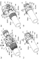
- the elastic sleeve 20 is obtained by moving the divided holders 30a and 30b, which are divided into a plurality of parts, toward each other in the radial direction with a fastening component 30c such as a bolt.
- a split type compression means that is pressed in the radial direction and deforms by reducing the diameter. More specifically, as shown in FIGS. 3(a) to 3(d), the split type compression means has a plurality of split holders 30a and 30b that are split in the radial direction and a plurality of split holders 30a and 30b. And a fastening component 30c that moves closer to each other in the direction.
- the elastic sleeve 20 is contracted and deformed by the approaching movement of the plurality of divided holders 30a and 30b by the fastening component 30c.
- a plurality of split holders 30a and 30b are formed in a symmetrical shape by radially dividing the cylindrical body into two parts, and extend over the peripheral end portion 30d of the split holders 30a and 30b, such as a screw part of a bolt.
- the holder holders 30a and 30b are configured to be moved closer to each other in the radial direction by inserting and rotating the fastening component 30c.
- a stopper portion 30e provided so as to radially face the outer surface 20b of the elastic sleeve 20 over the peripheral end portions 30d of the plurality of divided holders 30a and 30b is provided.
- the stopper portion 30e has a guide surface 30f that comes into radial contact with a surplus portion (not shown) of the elastic sleeve 20 that has been reduced in diameter due to the approaching movement of the plurality of divided holders 30a and 30b by the fastening component 30c. There is.
- the surplus portion of the outer surface 20b of the elastic sleeve 20 has a plurality of circumferentially adjacent split holders 30a, 30b. Even if an attempt is made to bulge between the peripheral end portions 30d, the guide surface 30f of the stopper portion 30e comes into radial contact with the outer surface of the excessively thickened portion of the sleeve outer surface 20b, so that the excessively thickened portion of the outer sleeve surface 20b swells. Is suppressed.
- the excess portion of the sleeve outer surface 20b does not enter between the peripheral end portions 30d of the plurality of divided holders 30a and 30b, but is guided in the circumferential direction to prevent the bite from being caught, and the plurality of divided holders 30a and 30b are fastened. It is possible to complete (completely tighten) with the component 30c.
- a cylindrical body is divided into three or four or more as a plurality of division holders 30a and 30b, and each of them is moved closer to a plurality of radial directions by a fastening component 30c. Things can be changed.
- the elastic sleeve 20 is compressed and deformed by the tightening member 30 shown in FIG.
- the flexible tube B (connection end portion Ba) is radially sandwiched between the sleeve 20 and the sleeve inner surface 20a.
- the flexible tube B (connection end portion Ba) is sandwiched in the nipple 11 so as not to come off in the axial direction.
- the flexible tube B (a part of the connecting end portion Ba) is compressed and deformed in the radial direction due to the sandwiching of the both, and the sandwiching portion Bb. Becomes When the flexible tube B is used in this tightened state, the flexible tube B (the portion excluding the connecting end portion Ba) is attached to the nipple 11 and the elastic sleeve 20 as shown by the chain double-dashed line in FIG.
- the non-sandwiched portion Bc adjacent to the sandwiched portion Bb is partially bent and deformed in the radial direction, and at the same time, is also stretched and deformed in the axial direction. For this reason, stress (pressure) is accumulated in the boundary portion between the sandwiched portion Bb and the non-sandwiched portion Bc due to the concentrated load due to the bending deformation and the elastic deformation. In such a situation, when the flexible tube B is made of a soft material such as silicone rubber, it is easily broken if a slight break is made.
- the flexible tube B (the portion excluding the connection end portion Ba) can be bent or expanded/contracted by pressing the inner surface B1 of the sandwiched portion Bb against the large-diameter cylindrical surface 11b in a smooth manner.
- the material forming the sandwiched portion Bb can move smoothly along the large-diameter cylindrical surface 11b toward the non-sandwiched portion Bc, and the load is dispersed. Therefore, when the amount of movement of the constituent material from the sandwiched portion Bb to the non-sandwiched portion Bc increases, the material becomes stress-free, and no break occurs at the boundary portion between the sandwiched portion Bb and the non-sandwiched portion Bc.
- the flexible tube B can be prevented from slipping out for a long period of time without being broken as the flexible tube B is bent.
- the function of preventing the flexible tube B from bursting due to breakage and the function of preventing the flexible tube B from coming off can be maintained for a long period of time, an accident such as fluid leakage can be prevented, and safety and economy are excellent.
- the cylindrical inner surface 23 of the sleeve inner surface 20a is formed so as to partially project in the radial direction toward the outer surface B2 of the flexible tube B.
- the cylindrical inner surface 23 that partially protrudes from the sleeve inner surface 20a bites into the outer surface B2 of the flexible tube B and is pressed by the cylindrical inner surface 23.
- the inner surface B1 of the sandwiching portion Bb of the flexible tube B is brought into close contact with the large-diameter cylindrical surface 11b of the nipple 11.
- the pull-out strength and airtightness of the flexible tube B with respect to the large-diameter cylindrical surface 11b of the nipple 11 can be improved.
- the function of preventing the flexible tube B from coming off is strengthened, more stable and stable pipe connection can be maintained for a long period of time, accidents such as fluid leakage can be further prevented, and safety can be further improved. ..
- the outer peripheral surface 11a of the nipple 11 has an annular groove 11c provided axially adjacent to the large-diameter cylindrical surface 11b, and the sleeve inner surface 20a extends radially with the annular groove 11c with the flexible tube B interposed therebetween. It is preferable to have the annular ribs 24 provided so as to face each other. In this case, the annular rib 24 of the sleeve inner surface 20a bites into the outer surface B2 of the flexible tube B in the tightened state shown in FIG. The inner surface B1 of the holding part Bb is fitted into the annular groove 11c of the nipple 11.
- the inner surface B1 of the flexible tube B is fitted into the large-diameter cylindrical surface 11b and the annular groove 11c in the axial direction, respectively, and the flexible tube B is axially positioned. Therefore, the flexible tube B can be pressed in the axial direction so as not to come off. As a result, the function of preventing the flexible tube B from coming off is further strengthened, the pipe connection can be maintained more stably for a long period of time, accidents such as fluid leakage can be prevented, and safety can be further improved.
- the cylindrical inner surface 23 protruding radially from the sleeve inner surface 20a toward the outer surface B2 of the flexible tube B is formed to have a smaller projection amount than the annular rib 24.
- the biting amount of the cylindrical inner surface 23 with respect to the outer surface B2 of the flexible tube B is larger than the biting amount of the annular rib 24 with respect to the outer surface B2 of the flexible tube B. Also few. Therefore, due to the use of the flexible tube B or the like, the flexible tube B (the portion excluding the connecting end portion Ba) is larger than the nipple 11 and the elastic sleeve 20 as shown by the chain double-dashed line in FIG.
- the split type compression means is used as a specific example of the tightening member 30, but the invention is not limited to this, and instead of the split type compression means, the bag described in Japanese Patent Laid-Open No. 2001-193876. You may change to another fastening means, such as using a nut.
Abstract
La présente invention a pour objectif d'empêcher qu'un tube flexible (B) ne rompe même lorsque le tube flexible (B) est plié et d'empêcher que le tube flexible (B) ne se détache pendant une longue période même lorsque le tube flexible (B) est composé d'un matériau souple tel que du caoutchouc de silicone. Un raccord de tuyau comprend : un mamelon cylindrique disposé le long d'un espace d'insertion d'un tube flexible ; un manchon élastique qui est déformable dans la direction radiale, le manchon élastique étant disposé de manière à intercaler, dans la direction radiale, l'espace d'insertion du tube flexible avec la surface circonférentielle externe du mamelon ; et un élément de serrage disposé à l'extérieur du manchon élastique, l'élément de serrage présentant une partie de pression pressant le manchon élastique contre le mamelon, le mamelon présentant une surface cylindrique de grand diamètre qui est lisse dans la direction axiale, au niveau de l'extrémité dans la direction axiale de la surface circonférentielle externe, la surface cylindrique pressant contre la surface interne du tube flexible dans la direction radiale, et le manchon élastique présentant une surface interne cylindrique qui est lisse dans la direction axiale, sur la surface interne de manchon qui est opposée sur le tube flexible à la surface cylindrique de grand diamètre du mamelon dans la direction radiale, la surface interne cylindrique pressant contre la surface externe du tube flexible.
Priority Applications (3)
| Application Number | Priority Date | Filing Date | Title |
|---|---|---|---|
| EP20754138.4A EP3926224A4 (fr) | 2019-02-12 | 2020-02-07 | Raccord de tuyau |
| US17/425,097 US20220107042A1 (en) | 2019-02-12 | 2020-02-07 | Hose joint |
| CN202080011796.4A CN113383186A (zh) | 2019-02-12 | 2020-02-07 | 管接头 |
Applications Claiming Priority (2)
| Application Number | Priority Date | Filing Date | Title |
|---|---|---|---|
| JP2019-022779 | 2019-02-12 | ||
| JP2019022779A JP6798713B2 (ja) | 2019-02-12 | 2019-02-12 | 管継手 |
Publications (1)
| Publication Number | Publication Date |
|---|---|
| WO2020166516A1 true WO2020166516A1 (fr) | 2020-08-20 |
Family
ID=72043858
Family Applications (1)
| Application Number | Title | Priority Date | Filing Date |
|---|---|---|---|
| PCT/JP2020/004879 WO2020166516A1 (fr) | 2019-02-12 | 2020-02-07 | Raccord de tuyau |
Country Status (5)
| Country | Link |
|---|---|
| US (1) | US20220107042A1 (fr) |
| EP (1) | EP3926224A4 (fr) |
| JP (1) | JP6798713B2 (fr) |
| CN (1) | CN113383186A (fr) |
| WO (1) | WO2020166516A1 (fr) |
Families Citing this family (1)
| Publication number | Priority date | Publication date | Assignee | Title |
|---|---|---|---|---|
| JP2022108189A (ja) * | 2021-01-12 | 2022-07-25 | ニッタ株式会社 | ホース用継手 |
Citations (5)
| Publication number | Priority date | Publication date | Assignee | Title |
|---|---|---|---|---|
| JP2001193876A (ja) | 2000-01-12 | 2001-07-17 | Nippon Flex Kk | ホースコネクタ |
| JP2009270622A (ja) * | 2008-05-07 | 2009-11-19 | Toyox Co Ltd | 管継手 |
| US20100102551A1 (en) * | 2008-10-27 | 2010-04-29 | Dennis Zeiber | Hose coupling |
| JP2011102605A (ja) * | 2009-11-10 | 2011-05-26 | Toyox Co Ltd | ホース継手 |
| JP2015517067A (ja) * | 2012-04-17 | 2015-06-18 | オプシェストヴォ サグラニチェノイ オトヴェトストヴェンノスチユ “グルーパ ポリメルテプロ” | ポリマー管継手アセンブリ |
Family Cites Families (13)
| Publication number | Priority date | Publication date | Assignee | Title |
|---|---|---|---|---|
| US3222091A (en) * | 1962-08-30 | 1965-12-07 | Dixon Valve & Coupling Co | Pressure responsive fluid tight hose coupling |
| GB2022744B (en) * | 1978-06-06 | 1982-09-02 | Duffield Ltd F | Hose and fitting |
| JPS5962388U (ja) * | 1982-10-16 | 1984-04-24 | 小杉 一雄 | 管継手 |
| US4653779A (en) * | 1986-03-17 | 1987-03-31 | Dayco Products, Inc. | Hose coupling and method of making the same |
| DE3627274A1 (de) * | 1986-08-12 | 1988-02-18 | Widenmann Max Armaturen | Schlaucheinband |
| US5267758A (en) * | 1991-07-18 | 1993-12-07 | The Gates Rubber Company | Ferrule coupling having a C-shaped insert |
| AT8016U1 (de) * | 2001-08-13 | 2005-12-15 | Geiser Friedrich | Schlauch-klemmvorrichtung |
| JP2011102606A (ja) * | 2009-11-10 | 2011-05-26 | Toyox Co Ltd | ホース継手 |
| PL2322831T3 (pl) * | 2009-11-12 | 2013-10-31 | Thomas Reckzeh | Zaciskowe złącze rurowe, zwłaszcza do łączenia rur wielowarstwowych jak również sposób zamocowania zaciskowego złącza rurowego |
| CN102906481B (zh) * | 2010-06-11 | 2015-07-01 | 东拓工业株式会社 | 管端接头 |
| MY167445A (en) * | 2011-10-20 | 2018-08-28 | Toyox Kk | Tube joint |
| DE202012101020U1 (de) * | 2012-03-22 | 2012-07-10 | Schwer Fittings Gmbh | Vorrichtung zur Verbindung eines Schlauchendes |
| JP5953586B2 (ja) * | 2014-04-11 | 2016-07-20 | 株式会社トヨックス | 管継手 |
-
2019
- 2019-02-12 JP JP2019022779A patent/JP6798713B2/ja active Active
-
2020
- 2020-02-07 WO PCT/JP2020/004879 patent/WO2020166516A1/fr unknown
- 2020-02-07 EP EP20754138.4A patent/EP3926224A4/fr active Pending
- 2020-02-07 CN CN202080011796.4A patent/CN113383186A/zh active Pending
- 2020-02-07 US US17/425,097 patent/US20220107042A1/en active Pending
Patent Citations (5)
| Publication number | Priority date | Publication date | Assignee | Title |
|---|---|---|---|---|
| JP2001193876A (ja) | 2000-01-12 | 2001-07-17 | Nippon Flex Kk | ホースコネクタ |
| JP2009270622A (ja) * | 2008-05-07 | 2009-11-19 | Toyox Co Ltd | 管継手 |
| US20100102551A1 (en) * | 2008-10-27 | 2010-04-29 | Dennis Zeiber | Hose coupling |
| JP2011102605A (ja) * | 2009-11-10 | 2011-05-26 | Toyox Co Ltd | ホース継手 |
| JP2015517067A (ja) * | 2012-04-17 | 2015-06-18 | オプシェストヴォ サグラニチェノイ オトヴェトストヴェンノスチユ “グルーパ ポリメルテプロ” | ポリマー管継手アセンブリ |
Non-Patent Citations (1)
| Title |
|---|
| See also references of EP3926224A4 |
Also Published As
| Publication number | Publication date |
|---|---|
| US20220107042A1 (en) | 2022-04-07 |
| JP6798713B2 (ja) | 2020-12-09 |
| JP2020133640A (ja) | 2020-08-31 |
| EP3926224A1 (fr) | 2021-12-22 |
| EP3926224A4 (fr) | 2022-10-26 |
| CN113383186A (zh) | 2021-09-10 |
Similar Documents
| Publication | Publication Date | Title |
|---|---|---|
| JP5557221B2 (ja) | 管継手 | |
| WO2013115044A1 (fr) | Joint de tuyau | |
| WO2015029815A1 (fr) | Raccord de tube | |
| WO2015156198A1 (fr) | Raccord de tuyau | |
| WO2020166516A1 (fr) | Raccord de tuyau | |
| JP6078857B2 (ja) | 管継手 | |
| JP2015203439A5 (fr) | ||
| WO2011058877A1 (fr) | Raccord de tuyau | |
| JP2020133640A5 (fr) | ||
| WO2021220457A1 (fr) | Manchon pour raccord de tuyau et raccord de tuyau pourvu dudit manchon pour raccord de tuyau | |
| JP6765729B2 (ja) | 管継手用スリーブ | |
| JP5849261B2 (ja) | 管継手 | |
| JP6010831B2 (ja) | 管継手構造 | |
| JP2013040645A (ja) | 管継手 | |
| JP5273493B2 (ja) | 管接続用バンドセット及び緊締バンド用アタッチメント | |
| TWI809270B (zh) | 管接頭用套筒 | |
| JP5584378B1 (ja) | 管継手 | |
| WO2023199769A1 (fr) | Raccord de tuyau et manchon destiné à être utilisé pour un raccord de tuyau | |
| JP5799326B2 (ja) | 管継手 | |
| JP7100850B2 (ja) | 管継手 | |
| JP6770753B2 (ja) | 管継手 | |
| WO2013108679A1 (fr) | Jeu de colliers de raccordement pour tube et collier de fixation | |
| WO2023199770A1 (fr) | Raccord de tuyau | |
| JPS587180Y2 (ja) | 軟質管管継手装置 | |
| JP2017067097A (ja) | 管締結構造及び管締め付け具 |
Legal Events
| Date | Code | Title | Description |
|---|---|---|---|
| 121 | Ep: the epo has been informed by wipo that ep was designated in this application |
Ref document number: 20754138 Country of ref document: EP Kind code of ref document: A1 |
|
| NENP | Non-entry into the national phase |
Ref country code: DE |
|
| ENP | Entry into the national phase |
Ref document number: 2020754138 Country of ref document: EP Effective date: 20210913 |