WO2020166516A1 - Pipe joint - Google Patents
Pipe joint Download PDFInfo
- Publication number
- WO2020166516A1 WO2020166516A1 PCT/JP2020/004879 JP2020004879W WO2020166516A1 WO 2020166516 A1 WO2020166516 A1 WO 2020166516A1 JP 2020004879 W JP2020004879 W JP 2020004879W WO 2020166516 A1 WO2020166516 A1 WO 2020166516A1
- Authority
- WO
- WIPO (PCT)
- Prior art keywords
- flexible tube
- nipple
- sleeve
- elastic sleeve
- cylindrical
- Prior art date
Links
Images


Classifications
-
- F—MECHANICAL ENGINEERING; LIGHTING; HEATING; WEAPONS; BLASTING
- F16—ENGINEERING ELEMENTS AND UNITS; GENERAL MEASURES FOR PRODUCING AND MAINTAINING EFFECTIVE FUNCTIONING OF MACHINES OR INSTALLATIONS; THERMAL INSULATION IN GENERAL
- F16L—PIPES; JOINTS OR FITTINGS FOR PIPES; SUPPORTS FOR PIPES, CABLES OR PROTECTIVE TUBING; MEANS FOR THERMAL INSULATION IN GENERAL
- F16L33/00—Arrangements for connecting hoses to rigid members; Rigid hose connectors, i.e. single members engaging both hoses
- F16L33/22—Arrangements for connecting hoses to rigid members; Rigid hose connectors, i.e. single members engaging both hoses with means not mentioned in the preceding groups for gripping the hose between inner and outer parts
- F16L33/23—Arrangements for connecting hoses to rigid members; Rigid hose connectors, i.e. single members engaging both hoses with means not mentioned in the preceding groups for gripping the hose between inner and outer parts the outer parts being segmented, the segments being pressed against the hose by tangentially arranged members
Definitions
- the present invention relates to a pipe joint used for connecting a flexible pipe such as a hose or a tube formed of a soft and soft material such as silicone rubber to a pipe.
- a tubular nipple in which a projection slightly larger than the inner diameter of the hose is formed, and a radially deformable sleeve provided so as to radially face the outer surface of the hose.
- a hose connector provided with a cap nut provided outside the sleeve to reduce the sleeve (for example, refer to Patent Document 1).
- a plurality of protrusions are formed in the shape of a bamboo in the axial direction to prevent the hose from slipping.
- a large number of circumferential projections are formed continuously in the axial direction in order to easily bite (adhere) to the outer surface of the hose.
- the inner surface of the cap nut has a pressing portion that shrinks the sleeve as it moves in the axial direction with respect to the nipple, and due to the contracting deformation of the sleeve, the peripheral projections come into close contact with the outer surface of the hose, and the inner surface of the hose has the inner surface of the nipple. Stick to.
- silicone rubber having excellent characteristics such as heat resistance, cold resistance, low elution property, high insulation property, and tasteless and odorless has been attracting attention. It is required in the semiconductor industry, chemical industry, etc. Flexible tubes made of silicone rubber are softer and generally inferior in tear strength and tensile strength as compared with commonly used synthetic resin tubes, and easily break if a slight cut is made. Care must be taken when tightening the pipe.
- a hose is radially sandwiched between the bamboo shoot-shaped projections on the outer circumference of the nipple and the circumferential projections on the inner surface of the sleeve for tightening.
- the hose is a flexible tube made of a soft material such as silicone, bend the hose tightly between the bamboo ridges of the nipple and the circumferential ridges of the sleeve, and bend the hose to form the bamboo ridges of the nipple.
- a soft material such as silicone
- the protrusions and the peripheral protrusions of the sleeve would bite into and hurt the inner and outer surfaces of the hose.
- the hose is a flexible tube made of a material with poor tear strength, such as silicone rubber, even if a small cut is made on the inner surface or a part of the outer surface, the cut will spread and burst. , There was a problem of developing into a serious fluid leakage accident.
- a pipe joint includes a cylindrical nipple provided along an insertion space of a flexible tube, and the insertion of the flexible tube between an outer peripheral surface of the nipple.
- a radially deformable elastic sleeve provided so as to sandwich the space in the radial direction, and a tightening member having a pressing portion that is provided outside the elastic sleeve and presses the elastic sleeve toward the nipple
- the nipple has an axially smooth large-diameter cylindrical surface that is in radial contact with the inner surface of the flexible tube at the axial tip of the outer peripheral surface, and the elastic sleeve is the flexible tube.
- the inner surface of the sleeve which faces the large-diameter cylindrical surface of the nipple in the radial direction, with the inner surface of the nipple having a smooth cylindrical inner surface in pressure contact with the outer surface of the flexible tube in the axial direction.
- the pipe joint A has an elastic sleeve on the outside of the flexible pipe B after the flexible pipe B is inserted into the nipple 11 of the joint body 10. It is a connector that covers 20 and presses the elastic sleeve 20 and the flexible tube B toward the nipple 11 with the tightening member 30.
- a flexible pipe B made of a soft and soft material such as silicone rubber is radially inserted between a cylindrical nipple 11 and an elastic sleeve 20 which is deformable in the radial direction, and the elastic sleeve 20 Due to the reduced diameter deformation, the flexible tube B is pressed toward the outer peripheral surface 11a of the nipple 11 and tightened. As a result, the flexible tube B is sandwiched between the nipple 11 and the elastic sleeve 20 and is connected so that it cannot be pulled out.
- the pipe joint A is configured such that the nipple 11 provided along the insertion space S of the flexible tube B and the elasticity provided so as to surround the outer periphery of the insertion space S of the flexible tube B.
- the sleeve 20 and a tightening member 30 that is provided outside the elastic sleeve 20 and presses the elastic sleeve 20 toward the nipple 11 are provided as main components.
- the flexible tube B is made of a soft and soft material such as silicone rubber or other rubber, or a soft synthetic resin such as vinyl chloride, and is a flexible tubular body such as a hose or tube that is elastically deformable.
- the flexible tube B is preferably a tubular body such as a hose or tube made of a soft material containing a silicone rubber that is softer than a general soft synthetic resin such as vinyl chloride and has a lower tear strength or tensile strength. ..
- a tube body having a flat inner surface B1 and a flat outer surface B2 is used, or at least a connecting end portion Ba having a predetermined length from the cut surface B3 has a flat inner surface B1 and an outer surface B2.
- connection end portion Ba of the flexible tube B is inserted into the insertion space S.
- the tube body of the flexible tube B is formed in a single-layer structure or a multi-layer structure or a multi-layer structure having a plurality of layers.
- a hose having a single-layer structure is used in the illustrated example.
- the flexible tube B may be replaced by a tube body having a single-layer structure and a tube body having a multilayer structure or the like.
- a plurality of or single synthetic resin blades are spirally embedded as an intermediate layer between a transparent or opaque outer layer and an inner layer.
- a spiral reinforcing hose in which a wire made of a metal or a wire made of a hard synthetic resin is embedded in a spiral shape.
- the joint body 10 is made of a metal such as rust-resistant stainless steel or brass, or a rigid material such as a hard synthetic resin, and is formed in a substantially cylindrical shape having a large wall thickness. Alternatively, it is formed by pressing or other forming process.
- the joint body 10 has a cylindrical nipple 11 and a connecting portion 12 for connecting to another pipe body (not shown) or a pipe connection port (not shown) of another device.
- the nipple 11 is formed on the tip side of the joint body 10 so as to radially face the inner surface B1 of the flexible tube B (connection end portion Ba), and the connection portion 12 is formed on the base end side of the joint body 10. Has been done.
- the nipple 11 is formed in a cylindrical shape having substantially the same inner diameter as the flexible tube B (connection end portion Ba) or an outer diameter slightly smaller than the inner diameter of the flexible tube B (connection end portion Ba), and the insertion space S It has an outer peripheral surface 11a radially opposite to the inner surface B1 of the flexible tube B inserted in.
- the outer peripheral surface 11a of the nipple 11 has a large-diameter cylindrical surface 11b, which is in pressure contact with the inner surface B1 of the flexible tube B in the radial direction at the tip in the axial direction.
- the large-diameter cylindrical surface 11b is formed in a non-inclined smooth shape having the same outer diameter over a region of a predetermined length in the axial direction on the outer peripheral surface 11a of the nipple 11.
- the outer peripheral surface 11a of the nipple 11 preferably has an annular groove 11c provided axially adjacent to the large diameter cylindrical surface 11b.
- a plurality of annular grooves 11c are formed at predetermined intervals on the outer peripheral surface 11a of the nipple 11 toward the rear side (base end side of the joint body 10).
- a plurality of smooth large-diameter surfaces 11d having substantially the same outer diameter as the large-diameter cylindrical surface 11b are formed between the plurality of annular grooves 11c.
- the large-diameter cylindrical surface 11b, the plurality of annular grooves 11c, and the plurality of large-diameter surfaces 11d are formed in a concavo-convex shape so as to radially face the inner surface B1 of the flexible tube B, and have a function of preventing the flexible tube B from coming off. ing.
- the corner portion 11e of the large-diameter cylindrical surface 11b which is the tip edge of the nipple 11, be chamfered.
- the chamfer include R chamfering for machining the corner 11e into an arcuate cross section and C chamfering for obliquely cutting off the corner 11e.
- the outer peripheral surface 11a of the nipple 11 has a large diameter cylindrical surface 11b, a plurality of annular grooves 11c, and a plurality of large diameter surfaces 11d at the tip thereof. They are arranged alternately in the direction. In the case of the illustrated example, two large-diameter surfaces 11d are unevenly formed between the three annular grooves 11c.
- the corner portion 11e of the large-diameter cylindrical surface 11b, which is the tip edge of the nipple 11, is rounded as a chamfer.
- the outer peripheral surface 11a of the nipple 11 is provided with retaining means 13 for restricting a position of a tightening member 30 described later so as to be immovable in the axial direction.
- a collar-shaped engaging portion is formed between the nipple 11 of the joint body 10 and the connecting portion 12 as a retaining means 13 for the tightening member 30, which will be described later.
- the connecting portion 12 of the joint body 10 is a ferrule (ferrule), and another ferrule (not shown) formed at a pipe connection port of another device. ) And a connecting tool (not shown) called a clamp or a clamp band, etc.
- the arrangement location and the number of arrangement of the plurality of annular grooves 11c and the plurality of large-diameter surfaces 11d and the respective sizes may be changed to those other than the illustrated example, and a large size may be formed as a leading edge of the nipple 11. It is also possible to chamfer the corner 11e of the radial cylindrical surface 11b.
- the connecting portion 12 of the joint body 10 it is possible to form a screw portion, a tool engaging portion, or the like instead of the ferrule.
- the threaded portion serving as the connecting portion 12 of the joint body 10 is formed so as to be screwed into the threaded portion (not shown) at the pipe connection port of another device, and is engaged with a tool (not shown) such as a spanner or a wrench. By rotating the tool engaging portion, the screw parts are screwed together and detachably connected.
- the elastic sleeve 20 has excellent heat resistance such as soft synthetic resin containing rubber such as polyvinylidene fluoride (PVDF) or fluororesin, and flexible tube B.
- the elastic material is harder than the constituent material and is formed into a cylindrical shape that is elastically deformable in the radial direction by being elastically deformed at least in the circumferential direction.
- the elastic sleeve 20 is preferably a cylindrical body made of a hard material that is harder than a soft material containing silicone rubber and elastically deforms in the circumferential direction and the radial direction. As shown in FIGS.
- the elastic sleeve 20 is assembled so as to face the outside of the outer peripheral surface 11a of the nipple 11 in the radial direction with the insertion space S of the flexible tube B interposed therebetween. That is, in the set state of FIGS. 1A and 1B in which the elastic sleeve 20 is assembled to the flexible tube B inserted into the nipple 11, the sleeve inner surface 20a which is the inner peripheral surface of the elastic sleeve 20 has a flexible tube.
- the outer surface B2 of B (the connection end portion Ba) is radially opposed to the outer surface B of the elastic sleeve 20.
- the outer surface 20b of the elastic sleeve 20 is radially opposed to the tightening member 30 described later.
- the elastic sleeve 20 elastically contracts and expands in diameter as it is pressed by a tightening member 30 described later, so that the inner diameter at the time of the contraction is smaller than the outer diameter of the flexible tube B (connection end portion Ba).
- the inner diameter of the flexible tube B (connecting end portion Ba) is set to be substantially the same as or slightly larger than the outer diameter of the flexible tube B (connection end portion Ba).
- the elastic sleeve 20 has a plurality of slits 21 formed by notching and a plurality of strip plate portions 22 formed between the plurality of slits 21.
- the elastic sleeve 20 can be smoothly elastically deformed in the radial direction of the elastic sleeve 20 by the slits 21 and the strip plate portions 22.
- the plurality of slits 21 are arranged so as to extend in the axial direction at predetermined intervals in the circumferential direction of the elastic sleeve 20, and the plurality of band plate portions 22 formed between the slits 21 are substantially parallel to each other. It is located in.
- the plurality of slits 21 and the plurality of strip plate portions 22 gradually press the plurality of strip plate portions 22 toward each other in the circumferential direction by pressing the tightening member 30 described later, and at the same time, the intervals of the plurality of slits 21 in the circumferential direction.
- the elastic sleeve 20 is configured to be deformed by reducing the diameter as a whole.
- the pressing by the tightening member 30 is released to gradually separate the plurality of band plate portions 22 from each other in the circumferential direction, and at the same time, to widen the intervals of the plurality of slits 21 in the circumferential direction. It is configured to be expanded and deformed.
- the inner surface of the plurality of band plate portions 22 which is the inner peripheral surface of the elastic sleeve 20 (sleeve inner surface 20a) has a cylindrical inner surface 23 that radially faces the outer surface B2 of the flexible tube B.
- the sleeve inner surface 20a preferably has an annular rib 24 and a pressing convex portion 25 in addition to the cylindrical inner surface 23.
- the cylindrical inner surface 23 is formed in a non-inclined smooth shape having the same inner diameter over a region of a predetermined length in the axial direction that faces the large-diameter cylindrical surface 11b of the nipple 11 in the sleeve inner surface 20a.
- the inner surface 23 of the cylinder is preferably formed so as to partially project in the radial direction toward the outer surface B2 of the flexible tube B. Further, it is preferable that the corner portion 23a which is the tip edge of the inner surface 23 of the cylinder be chamfered. Examples of the chamfer include C-chamfering in which the corner 23a is cut off obliquely and R-chamfering in which the corner 23a is processed into an arcuate cross section.
- a plurality of annular ribs 24 are formed at predetermined intervals so as to face the annular groove 11c in the sleeve inner surface 20a with the flexible tube B interposed therebetween in the radial direction.
- the amount of protrusion of the cylindrical inner surface 23 radially protruding from the sleeve inner surface 20a toward the outer surface B2 of the flexible tube B is preferably smaller than the amount of protrusion of the annular rib 24.
- the pressing convex portion 25 is formed in an annular shape so as to project at a position distant from the large-diameter cylindrical surface 11b of the nipple 1 by a predetermined length in the axial direction at the tip edge of the sleeve inner surface 20a. It is formed.
- the inner surface B1 of the flexible tube B pressed inward in the radial direction is tapered by the inner peripheral surface 11f of the nipple 11. It is arranged to be continuous with the portion 11g.
- a plurality of slits 21 that extend linearly in the axial direction and are divided into a plurality of band plate portions 22 are provided on both sides of the elastic sleeve 20 in the axial direction.
- a plurality of slits 21 and strip plate portions 22 are arranged in the circumferential direction by reducing the width dimension of the plurality of strip plate portions 22 in the circumferential direction.
- a cylindrical inner surface 23 is projectingly formed on the tip side at the axially intermediate position, and two annular ribs 24 are projectingly formed at the axially intermediate position.
- a plurality of slits 21, a plurality of strip plate portions 22, and a plurality of coupling portions 26 are arranged in a non-staggered shape, and the plurality of slits 21 are formed in a non-linear shape such as a curved line. It is also possible to form notches so as to extend in a straight line, and to change the arrangement location and number of the cylindrical inner surface 23 and the plurality of annular ribs 24, or the size and shape of each, other than the illustrated example.
- a corner portion 23a which is a tip edge of the inner surface 23 of the cylinder is chamfered as a chamfering process.
- the elastic sleeve 20 is formed in a shape symmetrical in the axial direction. Thereby, the same function can be obtained even if the nipple 11 is rearranged in either the forward or reverse direction in the axial direction.
- the elastic sleeve 20 is divided in the circumferential direction at predetermined intervals.
- a plurality of belt-shaped bodies 20', 20" are formed.
- the plurality of belt-shaped bodies 20', 20" are formed so as to be able to expand and contract in the circumferential direction of the elastic sleeve 20, and the plurality of belt-shaped bodies 20', 20" are formed.
- the ends are integrally connected.
- the elastic sleeve 20 is divided into two halves in the circumferential direction, and a plurality of belt-shaped bodies 20′, 20′′ are injection-molded into the same shape, and one of the plurality of belt-shaped bodies 20′, 20′′ is formed.
- the other direction is changed (reversed), and they are connected by the fitting portions 27 provided at both ends of the plurality of strips 20', 20".
- the overall shape of the elastic sleeve 20 may be changed to an asymmetrical shape in the axial direction, the elastic sleeve 20 may be integrally molded into a substantially cylindrical shape, or the elastic sleeve 20 may be formed in the circumferential direction. It is also possible to change the number of divisions and the shape of the fitting portion 27 to a shape other than the illustrated example.
- the tightening member 30 is made of a metal such as rust-resistant stainless steel or brass, or a rigid material such as hard synthetic resin, and has an inner diameter slightly larger than the outer diameter of the elastic sleeve 20. It is a compression means that is formed in a cylindrical shape having a or a shape similar to that of a cylinder, and is used to deform the elastic sleeve 20 by reducing its diameter by an artificial operation.
- the tightening member 30 has a pressing portion 31 that radially faces the outer peripheral surface (sleeve outer surface 20b) of the elastic sleeve 20, and by pressing the sleeve outer surface 20b radially by the pressing portion 31 in accordance with an artificial operation.
- the flexible tube B (connecting end portion Ba) is configured to be deformed by reducing its diameter.
- a locking portion 32 that axially engages with the elastic sleeve 20 is provided on the inner periphery of the tightening member 30 that faces the sleeve outer surface 20b in the radial direction.
- the locking portion 32 causes the elastic sleeve 20 to move in the axial direction. It is preferably positioned immovably.
- the elastic sleeve 20 is obtained by moving the divided holders 30a and 30b, which are divided into a plurality of parts, toward each other in the radial direction with a fastening component 30c such as a bolt.
- a split type compression means that is pressed in the radial direction and deforms by reducing the diameter. More specifically, as shown in FIGS. 3(a) to 3(d), the split type compression means has a plurality of split holders 30a and 30b that are split in the radial direction and a plurality of split holders 30a and 30b. And a fastening component 30c that moves closer to each other in the direction.
- the elastic sleeve 20 is contracted and deformed by the approaching movement of the plurality of divided holders 30a and 30b by the fastening component 30c.
- a plurality of split holders 30a and 30b are formed in a symmetrical shape by radially dividing the cylindrical body into two parts, and extend over the peripheral end portion 30d of the split holders 30a and 30b, such as a screw part of a bolt.
- the holder holders 30a and 30b are configured to be moved closer to each other in the radial direction by inserting and rotating the fastening component 30c.
- a stopper portion 30e provided so as to radially face the outer surface 20b of the elastic sleeve 20 over the peripheral end portions 30d of the plurality of divided holders 30a and 30b is provided.
- the stopper portion 30e has a guide surface 30f that comes into radial contact with a surplus portion (not shown) of the elastic sleeve 20 that has been reduced in diameter due to the approaching movement of the plurality of divided holders 30a and 30b by the fastening component 30c. There is.
- the surplus portion of the outer surface 20b of the elastic sleeve 20 has a plurality of circumferentially adjacent split holders 30a, 30b. Even if an attempt is made to bulge between the peripheral end portions 30d, the guide surface 30f of the stopper portion 30e comes into radial contact with the outer surface of the excessively thickened portion of the sleeve outer surface 20b, so that the excessively thickened portion of the outer sleeve surface 20b swells. Is suppressed.
- the excess portion of the sleeve outer surface 20b does not enter between the peripheral end portions 30d of the plurality of divided holders 30a and 30b, but is guided in the circumferential direction to prevent the bite from being caught, and the plurality of divided holders 30a and 30b are fastened. It is possible to complete (completely tighten) with the component 30c.
- a cylindrical body is divided into three or four or more as a plurality of division holders 30a and 30b, and each of them is moved closer to a plurality of radial directions by a fastening component 30c. Things can be changed.
- the elastic sleeve 20 is compressed and deformed by the tightening member 30 shown in FIG.
- the flexible tube B (connection end portion Ba) is radially sandwiched between the sleeve 20 and the sleeve inner surface 20a.
- the flexible tube B (connection end portion Ba) is sandwiched in the nipple 11 so as not to come off in the axial direction.
- the flexible tube B (a part of the connecting end portion Ba) is compressed and deformed in the radial direction due to the sandwiching of the both, and the sandwiching portion Bb. Becomes When the flexible tube B is used in this tightened state, the flexible tube B (the portion excluding the connecting end portion Ba) is attached to the nipple 11 and the elastic sleeve 20 as shown by the chain double-dashed line in FIG.
- the non-sandwiched portion Bc adjacent to the sandwiched portion Bb is partially bent and deformed in the radial direction, and at the same time, is also stretched and deformed in the axial direction. For this reason, stress (pressure) is accumulated in the boundary portion between the sandwiched portion Bb and the non-sandwiched portion Bc due to the concentrated load due to the bending deformation and the elastic deformation. In such a situation, when the flexible tube B is made of a soft material such as silicone rubber, it is easily broken if a slight break is made.
- the flexible tube B (the portion excluding the connection end portion Ba) can be bent or expanded/contracted by pressing the inner surface B1 of the sandwiched portion Bb against the large-diameter cylindrical surface 11b in a smooth manner.
- the material forming the sandwiched portion Bb can move smoothly along the large-diameter cylindrical surface 11b toward the non-sandwiched portion Bc, and the load is dispersed. Therefore, when the amount of movement of the constituent material from the sandwiched portion Bb to the non-sandwiched portion Bc increases, the material becomes stress-free, and no break occurs at the boundary portion between the sandwiched portion Bb and the non-sandwiched portion Bc.
- the flexible tube B can be prevented from slipping out for a long period of time without being broken as the flexible tube B is bent.
- the function of preventing the flexible tube B from bursting due to breakage and the function of preventing the flexible tube B from coming off can be maintained for a long period of time, an accident such as fluid leakage can be prevented, and safety and economy are excellent.
- the cylindrical inner surface 23 of the sleeve inner surface 20a is formed so as to partially project in the radial direction toward the outer surface B2 of the flexible tube B.
- the cylindrical inner surface 23 that partially protrudes from the sleeve inner surface 20a bites into the outer surface B2 of the flexible tube B and is pressed by the cylindrical inner surface 23.
- the inner surface B1 of the sandwiching portion Bb of the flexible tube B is brought into close contact with the large-diameter cylindrical surface 11b of the nipple 11.
- the pull-out strength and airtightness of the flexible tube B with respect to the large-diameter cylindrical surface 11b of the nipple 11 can be improved.
- the function of preventing the flexible tube B from coming off is strengthened, more stable and stable pipe connection can be maintained for a long period of time, accidents such as fluid leakage can be further prevented, and safety can be further improved. ..
- the outer peripheral surface 11a of the nipple 11 has an annular groove 11c provided axially adjacent to the large-diameter cylindrical surface 11b, and the sleeve inner surface 20a extends radially with the annular groove 11c with the flexible tube B interposed therebetween. It is preferable to have the annular ribs 24 provided so as to face each other. In this case, the annular rib 24 of the sleeve inner surface 20a bites into the outer surface B2 of the flexible tube B in the tightened state shown in FIG. The inner surface B1 of the holding part Bb is fitted into the annular groove 11c of the nipple 11.
- the inner surface B1 of the flexible tube B is fitted into the large-diameter cylindrical surface 11b and the annular groove 11c in the axial direction, respectively, and the flexible tube B is axially positioned. Therefore, the flexible tube B can be pressed in the axial direction so as not to come off. As a result, the function of preventing the flexible tube B from coming off is further strengthened, the pipe connection can be maintained more stably for a long period of time, accidents such as fluid leakage can be prevented, and safety can be further improved.
- the cylindrical inner surface 23 protruding radially from the sleeve inner surface 20a toward the outer surface B2 of the flexible tube B is formed to have a smaller projection amount than the annular rib 24.
- the biting amount of the cylindrical inner surface 23 with respect to the outer surface B2 of the flexible tube B is larger than the biting amount of the annular rib 24 with respect to the outer surface B2 of the flexible tube B. Also few. Therefore, due to the use of the flexible tube B or the like, the flexible tube B (the portion excluding the connecting end portion Ba) is larger than the nipple 11 and the elastic sleeve 20 as shown by the chain double-dashed line in FIG.
- the split type compression means is used as a specific example of the tightening member 30, but the invention is not limited to this, and instead of the split type compression means, the bag described in Japanese Patent Laid-Open No. 2001-193876. You may change to another fastening means, such as using a nut.
Abstract
The purpose is to prevent a flexible tube B from breaking even when the flexible tube B is bended and to prevent the flexible tube B from coming off for a long time, even when the flexible tube B is made of a soft material such as silicone rubber. A pipe joint comprises: a cylindrical nipple provided along an insertion space of a flexible tube; an elastic sleeve that is deformable in the radial direction, the elastic sleeve being provided so as to sandwich, in the radial direction, the insertion space of the flexible tube with the outer circumferential surface of the nipple; and a tightening member provided outside the elastic sleeve, the tightening member having a pressing portion pressing the elastic sleeve against the nipple, wherein the nipple has a large diameter cylindrical surface that is smooth in the axial direction, at the end in the axial direction of the outer circumferential surface, the cylindrical surface pressing against the inner surface of the flexible tube in the radial direction, and the elastic sleeve has a cylindrical inner surface that is smooth in the axial direction, on the sleeve inner surface that is opposed across the flexible tube to the large diameter cylindrical surface of the nipple in the radial direction, the cylindrical inner surface pressing against the outer surface of the flexible tube.
Description
本発明は、例えばシリコーンゴムなどの柔らかい軟質材料で形成されたホースやチューブなどからなる可撓管を配管接続するために用いられる管継手に関する。
The present invention relates to a pipe joint used for connecting a flexible pipe such as a hose or a tube formed of a soft and soft material such as silicone rubber to a pipe.
従来、この種の管継手として、ホースの内径より僅かに大きい程度の突起が形成される筒状のニップルと、ホースの外面と径方向へ対向して設けられた径方向へ変形可能なスリーブと、スリーブの外側に設けられてスリーブを縮小させる袋ナットと、を備えたホースコネクタがある(例えば、特許文献1参照)。
ニップルの外周には、複数の突起が軸方向へ竹の子状に形成されて、ホースの滑り止め作用をなしている。
スリーブの内面には、ホースの外面に食い込み(密着)易くするために多数の周突起が軸方向へ連続状に形成されている。
袋ナットの内面には、ニップルに対する軸方向への移動に伴ってスリーブを縮小させる押圧部を有し、スリーブの縮小変形により周突起がホースの外面と密着するとともに、ホースの内面がニップルの外周に密着する。 Conventionally, as this type of pipe joint, a tubular nipple in which a projection slightly larger than the inner diameter of the hose is formed, and a radially deformable sleeve provided so as to radially face the outer surface of the hose. There is a hose connector provided with a cap nut provided outside the sleeve to reduce the sleeve (for example, refer to Patent Document 1).
On the outer periphery of the nipple, a plurality of protrusions are formed in the shape of a bamboo in the axial direction to prevent the hose from slipping.
On the inner surface of the sleeve, a large number of circumferential projections are formed continuously in the axial direction in order to easily bite (adhere) to the outer surface of the hose.
The inner surface of the cap nut has a pressing portion that shrinks the sleeve as it moves in the axial direction with respect to the nipple, and due to the contracting deformation of the sleeve, the peripheral projections come into close contact with the outer surface of the hose, and the inner surface of the hose has the inner surface of the nipple. Stick to.
ところで、ホースなどの可撓管の構成材料としては、耐熱性・耐寒性,低溶出性,高い絶縁性,無味・無臭などの優れた特性を有するシリコーンゴムが注目され、特に食品・飲料業界、半導体業界、化学業界などで要望されている。
シリコーンゴム製の可撓管は、一般的に使用される合成樹脂管に比べ柔らかくて引裂強さや引張強さに劣り、僅かな切れ目が入ると簡単に破断してしまうため、管継手における可撓管の締め付けに注意する必要がある。
しかし乍ら、特許文献1では、ニップルの外周の竹の子状突起と、スリーブの内面の周突起との間にホースを径方向へ挟み込んで締め付けている。このため、ホースがシリコーンのような柔らかい材料からなる可撓管である場合には、ニップルの竹の子状突起とスリーブの周突起との間に強く締め付けた状態で、ホースを曲げるとニップルの竹の子状突起やスリーブの周突起がホースの内面や外面に食い込み傷付けるおそれがあった。
特にホースがシリコーンゴムなどの引裂強さに劣る材料からなる可撓管である場合には、その内面や外面の一部に僅かな切れ目が入っただけでも、切れ目が一気に広がって破裂してしまい、重大な流体漏れ事故に発展するという問題があった。 By the way, as a constituent material of a flexible tube such as a hose, silicone rubber having excellent characteristics such as heat resistance, cold resistance, low elution property, high insulation property, and tasteless and odorless has been attracting attention. It is required in the semiconductor industry, chemical industry, etc.
Flexible tubes made of silicone rubber are softer and generally inferior in tear strength and tensile strength as compared with commonly used synthetic resin tubes, and easily break if a slight cut is made. Care must be taken when tightening the pipe.
However, in Patent Document 1, a hose is radially sandwiched between the bamboo shoot-shaped projections on the outer circumference of the nipple and the circumferential projections on the inner surface of the sleeve for tightening. Therefore, if the hose is a flexible tube made of a soft material such as silicone, bend the hose tightly between the bamboo ridges of the nipple and the circumferential ridges of the sleeve, and bend the hose to form the bamboo ridges of the nipple. There was a risk that the protrusions and the peripheral protrusions of the sleeve would bite into and hurt the inner and outer surfaces of the hose.
Especially when the hose is a flexible tube made of a material with poor tear strength, such as silicone rubber, even if a small cut is made on the inner surface or a part of the outer surface, the cut will spread and burst. , There was a problem of developing into a serious fluid leakage accident.
このような課題を解決するために本発明に係る管継手は、可撓管の挿入空間に沿って設けられる円筒状のニップルと、前記ニップルの外周面との間に前記可撓管の前記挿入空間を径方向へ挟み込むように設けられた径方向へ変形可能な弾性スリーブと、前記弾性スリーブの外側に設けられて前記弾性スリーブを前記ニップルに向け押し付ける押圧部を有する締め付け部材と、を備え、前記ニップルは、前記外周面の軸方向先端に前記可撓管の内表面と径方向へ対向して圧接する軸方向へ平滑な大径円筒面を有し、前記弾性スリーブは、前記可撓管を挟んで前記ニップルの前記大径円筒面と径方向へ対向するスリーブ内面に前記可撓管の外表面と圧接する軸方向へ平滑な円筒内面を有することを特徴とする。
In order to solve such a problem, a pipe joint according to the present invention includes a cylindrical nipple provided along an insertion space of a flexible tube, and the insertion of the flexible tube between an outer peripheral surface of the nipple. A radially deformable elastic sleeve provided so as to sandwich the space in the radial direction, and a tightening member having a pressing portion that is provided outside the elastic sleeve and presses the elastic sleeve toward the nipple, The nipple has an axially smooth large-diameter cylindrical surface that is in radial contact with the inner surface of the flexible tube at the axial tip of the outer peripheral surface, and the elastic sleeve is the flexible tube. The inner surface of the sleeve, which faces the large-diameter cylindrical surface of the nipple in the radial direction, with the inner surface of the nipple having a smooth cylindrical inner surface in pressure contact with the outer surface of the flexible tube in the axial direction.
以下、本発明の実施形態を図面に基づいて詳細に説明する。
本発明の実施形態に係る管継手Aは、図1~図3に示すように、継手本体10のニップル11に対して可撓管Bが差し込まれた後に、可撓管Bの外側に弾性スリーブ20を被せ、締め付け部材30で弾性スリーブ20及び可撓管Bをニップル11に向け押し付けるコネクタである。
管継手Aは、円筒状のニップル11と、径方向へ変形可能な弾性スリーブ20との間に、シリコーンゴムのような柔らかい軟質材料からなる可撓管Bを径方向へ挟み込んで、弾性スリーブ20の縮径変形により、可撓管Bがニップル11の外周面11aに向けて押圧されて締め付ける。これにより、ニップル11と弾性スリーブ20の間に可撓管Bが挟み込まれて引き抜き不能に接続される。
詳しく説明すると、本発明の実施形態に係る管継手Aは、可撓管Bの挿入空間Sに沿って設けられるニップル11と、可撓管Bの挿入空間Sの外周を囲むように設けられる弾性スリーブ20と、弾性スリーブ20の外側に設けられて弾性スリーブ20をニップル11に向け押し付ける締め付け部材30と、を主要な構成要素として備えている。 Hereinafter, embodiments of the present invention will be described in detail with reference to the drawings.
As shown in FIGS. 1 to 3, the pipe joint A according to the embodiment of the present invention has an elastic sleeve on the outside of the flexible pipe B after the flexible pipe B is inserted into thenipple 11 of the joint body 10. It is a connector that covers 20 and presses the elastic sleeve 20 and the flexible tube B toward the nipple 11 with the tightening member 30.
In the pipe joint A, a flexible pipe B made of a soft and soft material such as silicone rubber is radially inserted between acylindrical nipple 11 and an elastic sleeve 20 which is deformable in the radial direction, and the elastic sleeve 20 Due to the reduced diameter deformation, the flexible tube B is pressed toward the outer peripheral surface 11a of the nipple 11 and tightened. As a result, the flexible tube B is sandwiched between the nipple 11 and the elastic sleeve 20 and is connected so that it cannot be pulled out.
More specifically, the pipe joint A according to the embodiment of the present invention is configured such that thenipple 11 provided along the insertion space S of the flexible tube B and the elasticity provided so as to surround the outer periphery of the insertion space S of the flexible tube B. The sleeve 20 and a tightening member 30 that is provided outside the elastic sleeve 20 and presses the elastic sleeve 20 toward the nipple 11 are provided as main components.
本発明の実施形態に係る管継手Aは、図1~図3に示すように、継手本体10のニップル11に対して可撓管Bが差し込まれた後に、可撓管Bの外側に弾性スリーブ20を被せ、締め付け部材30で弾性スリーブ20及び可撓管Bをニップル11に向け押し付けるコネクタである。
管継手Aは、円筒状のニップル11と、径方向へ変形可能な弾性スリーブ20との間に、シリコーンゴムのような柔らかい軟質材料からなる可撓管Bを径方向へ挟み込んで、弾性スリーブ20の縮径変形により、可撓管Bがニップル11の外周面11aに向けて押圧されて締め付ける。これにより、ニップル11と弾性スリーブ20の間に可撓管Bが挟み込まれて引き抜き不能に接続される。
詳しく説明すると、本発明の実施形態に係る管継手Aは、可撓管Bの挿入空間Sに沿って設けられるニップル11と、可撓管Bの挿入空間Sの外周を囲むように設けられる弾性スリーブ20と、弾性スリーブ20の外側に設けられて弾性スリーブ20をニップル11に向け押し付ける締め付け部材30と、を主要な構成要素として備えている。 Hereinafter, embodiments of the present invention will be described in detail with reference to the drawings.
As shown in FIGS. 1 to 3, the pipe joint A according to the embodiment of the present invention has an elastic sleeve on the outside of the flexible pipe B after the flexible pipe B is inserted into the
In the pipe joint A, a flexible pipe B made of a soft and soft material such as silicone rubber is radially inserted between a
More specifically, the pipe joint A according to the embodiment of the present invention is configured such that the
可撓管Bは、例えばシリコーンゴムやその他のゴムなどの柔らかい軟質材料か、又は塩化ビニルなどの軟質合成樹脂で、弾性変形可能に成形された例えばホースやチューブなどの可撓性を有する管体である。特に可撓管Bは、塩化ビニルなどの一般的な軟質合成樹脂よりも柔らかくて引裂強さや引張強さに劣ったシリコーンゴムを含む軟質材料からなるホースやチューブなどの管体であることが好ましい。また可撓管Bとしては、全ての内表面B1と外表面B2が平坦な管体を用いるか、又は少なくとも切断面B3から所定長さの接続端部Baにおいて内表面B1と外表面B2が平坦な管体を用いることが好ましい。
挿入空間Sに対しては、図1(a)(b)に示されるように、可撓管Bの接続端部Baが差し込まれる。
可撓管Bの管本体は、単層構造又は複数の層を有する複数層構造や多層構造に形成される。
可撓管Bの具体例として、図示される例では単層構造のホースを用いている。
また、その他の例として図示しないが、可撓管Bとして単層構造の管体に代え、多層構造の管体などを用いることも可能である。多種類の可撓管Bの具体例としては、透明又は不透明な外層及び内層との間に中間層として、複数本か又は単数本の合成樹脂製ブレード(補強糸)が螺旋状に埋設される積層ホース(ブレードホース)や、中間層として合成樹脂製又は金属製の断面矩形などの帯状補強材と断面円形などの線状補強材を螺旋状に巻き付けて一体化した螺旋補強ホース(フォーランホース)や、金属製線材や硬質合成樹脂製線材を螺旋状に埋設した螺旋補強ホースなどが挙げられる。 The flexible tube B is made of a soft and soft material such as silicone rubber or other rubber, or a soft synthetic resin such as vinyl chloride, and is a flexible tubular body such as a hose or tube that is elastically deformable. Is. In particular, the flexible tube B is preferably a tubular body such as a hose or tube made of a soft material containing a silicone rubber that is softer than a general soft synthetic resin such as vinyl chloride and has a lower tear strength or tensile strength. .. As the flexible tube B, a tube body having a flat inner surface B1 and a flat outer surface B2 is used, or at least a connecting end portion Ba having a predetermined length from the cut surface B3 has a flat inner surface B1 and an outer surface B2. It is preferable to use a tubular body.
As shown in FIGS. 1A and 1B, the connection end portion Ba of the flexible tube B is inserted into the insertion space S.
The tube body of the flexible tube B is formed in a single-layer structure or a multi-layer structure or a multi-layer structure having a plurality of layers.
As a specific example of the flexible tube B, a hose having a single-layer structure is used in the illustrated example.
Further, as another example, although not shown, the flexible tube B may be replaced by a tube body having a single-layer structure and a tube body having a multilayer structure or the like. As a specific example of the various types of flexible tubes B, a plurality of or single synthetic resin blades (reinforcing threads) are spirally embedded as an intermediate layer between a transparent or opaque outer layer and an inner layer. A laminated hose (blade hose) or a spiral reinforcement hose (forlan hose) in which a belt-shaped reinforcing material having a rectangular cross section made of synthetic resin or metal and a linear reinforcing material having a circular cross section are spirally wound and integrated as an intermediate layer. ), a spiral reinforcing hose in which a wire made of a metal or a wire made of a hard synthetic resin is embedded in a spiral shape.
継手本体10は、図1(a)(b)などに示されるように、例えば錆難いステンレスや真鍮などの金属や硬質合成樹脂などの剛性材料で、肉厚が厚い略円筒状に形成されるか、又はプレス加工やその他の成形加工することで形成される。継手本体10は、円筒状のニップル11と、他の管体(図示しない)や他の機器の管接続口(図示しない)と接続するための接続部12と、を有している。
ニップル11は、継手本体10の先端側に可撓管B(接続端部Ba)の内表面B1と径方向へ対向するように形成され、接続部12は、継手本体10の基端側に形成されている。
ニップル11は、可撓管B(接続端部Ba)の内径と略同じか又は可撓管B(接続端部Ba)の内径よりも若干小さな外径を有する円筒状に形成され、挿入空間Sに差し込まれた可撓管Bの内表面B1と径方向へ対向する外周面11aを有している。 As shown in FIGS. 1A and 1B, thejoint body 10 is made of a metal such as rust-resistant stainless steel or brass, or a rigid material such as a hard synthetic resin, and is formed in a substantially cylindrical shape having a large wall thickness. Alternatively, it is formed by pressing or other forming process. The joint body 10 has a cylindrical nipple 11 and a connecting portion 12 for connecting to another pipe body (not shown) or a pipe connection port (not shown) of another device.
Thenipple 11 is formed on the tip side of the joint body 10 so as to radially face the inner surface B1 of the flexible tube B (connection end portion Ba), and the connection portion 12 is formed on the base end side of the joint body 10. Has been done.
Thenipple 11 is formed in a cylindrical shape having substantially the same inner diameter as the flexible tube B (connection end portion Ba) or an outer diameter slightly smaller than the inner diameter of the flexible tube B (connection end portion Ba), and the insertion space S It has an outer peripheral surface 11a radially opposite to the inner surface B1 of the flexible tube B inserted in.
ニップル11は、継手本体10の先端側に可撓管B(接続端部Ba)の内表面B1と径方向へ対向するように形成され、接続部12は、継手本体10の基端側に形成されている。
ニップル11は、可撓管B(接続端部Ba)の内径と略同じか又は可撓管B(接続端部Ba)の内径よりも若干小さな外径を有する円筒状に形成され、挿入空間Sに差し込まれた可撓管Bの内表面B1と径方向へ対向する外周面11aを有している。 As shown in FIGS. 1A and 1B, the
The
The
ニップル11の外周面11aは、軸方向先端に可撓管Bの内表面B1と径方向へ対向して圧接する大径円筒面11bを有する。
大径円筒面11bは、ニップル11の外周面11aにおいて軸方向へ所定長さの領域に亘り、外径が同じ非傾斜の平滑状に形成されている。
さらにニップル11の外周面11aは、大径円筒面11bと軸方向へ隣接して設けられる環状溝11cを有することが好ましい。
環状溝11cは、ニップル11の外周面11aにおいて奥側(継手本体10の基端側)に向け複数個それぞれ所定間隔毎に形成されている。
複数の環状溝11cの間には、大径円筒面11bと略同じ外径で平滑な大径面11dが複数形成される。大径円筒面11bと複数の環状溝11c及び複数の大径面11dは、可撓管Bの内表面B1と径方向へ対向して凹凸形成され、可撓管Bの抜け止め機能を有している。
ニップル11の先端縁となる大径円筒面11bの角部11eは、面取りされることが好ましい。面取りとしては、角部11eを断面円弧形状に加工するR面取りや角部11eを斜めに削り落とすC面取りなどが挙げられる。
またニップル11の内周面11fには、その先端へ向けて拡径されたテーパー部11gを形成することが好ましい。 The outerperipheral surface 11a of the nipple 11 has a large-diameter cylindrical surface 11b, which is in pressure contact with the inner surface B1 of the flexible tube B in the radial direction at the tip in the axial direction.
The large-diametercylindrical surface 11b is formed in a non-inclined smooth shape having the same outer diameter over a region of a predetermined length in the axial direction on the outer peripheral surface 11a of the nipple 11.
Further, the outerperipheral surface 11a of the nipple 11 preferably has an annular groove 11c provided axially adjacent to the large diameter cylindrical surface 11b.
A plurality ofannular grooves 11c are formed at predetermined intervals on the outer peripheral surface 11a of the nipple 11 toward the rear side (base end side of the joint body 10).
A plurality of smooth large-diameter surfaces 11d having substantially the same outer diameter as the large-diameter cylindrical surface 11b are formed between the plurality of annular grooves 11c. The large-diameter cylindrical surface 11b, the plurality of annular grooves 11c, and the plurality of large-diameter surfaces 11d are formed in a concavo-convex shape so as to radially face the inner surface B1 of the flexible tube B, and have a function of preventing the flexible tube B from coming off. ing.
It is preferable that thecorner portion 11e of the large-diameter cylindrical surface 11b, which is the tip edge of the nipple 11, be chamfered. Examples of the chamfer include R chamfering for machining the corner 11e into an arcuate cross section and C chamfering for obliquely cutting off the corner 11e.
In addition, it is preferable to form atapered portion 11g having an increased diameter toward the tip of the inner peripheral surface 11f of the nipple 11.
大径円筒面11bは、ニップル11の外周面11aにおいて軸方向へ所定長さの領域に亘り、外径が同じ非傾斜の平滑状に形成されている。
さらにニップル11の外周面11aは、大径円筒面11bと軸方向へ隣接して設けられる環状溝11cを有することが好ましい。
環状溝11cは、ニップル11の外周面11aにおいて奥側(継手本体10の基端側)に向け複数個それぞれ所定間隔毎に形成されている。
複数の環状溝11cの間には、大径円筒面11bと略同じ外径で平滑な大径面11dが複数形成される。大径円筒面11bと複数の環状溝11c及び複数の大径面11dは、可撓管Bの内表面B1と径方向へ対向して凹凸形成され、可撓管Bの抜け止め機能を有している。
ニップル11の先端縁となる大径円筒面11bの角部11eは、面取りされることが好ましい。面取りとしては、角部11eを断面円弧形状に加工するR面取りや角部11eを斜めに削り落とすC面取りなどが挙げられる。
またニップル11の内周面11fには、その先端へ向けて拡径されたテーパー部11gを形成することが好ましい。 The outer
The large-diameter
Further, the outer
A plurality of
A plurality of smooth large-
It is preferable that the
In addition, it is preferable to form a
継手本体10の具体例として図1~図3に示される場合には、ニップル11の外周面11aにおいて先端部分に、大径円筒面11bと複数の環状溝11c及び複数の大径面11dを軸方向へ交互に配置している。図示例の場合には、三つの環状溝11cの間に二つの大径面11dが凹凸形成されている。
ニップル11の先端縁となる大径円筒面11bの角部11eは、面取り加工としてR面取りされている。
ニップル11の外周面11aには、後述する締め付け部材30を軸方向への移動不能に位置規制するための抜け止め手段13が設けられている。図示例の場合には、継手本体10のニップル11と接続部12との間に後述する締め付け部材30の抜け止め手段13として鍔状係止部を突出形成している。
さらに継手本体10の接続部12が図3(a)~(d)に示されるように、へルール(フェルール)であり、他の機器の管接続口に形成される別のへルール(図示しない)と、クランプやクランプバンドなどと呼ばれる連結具(図示しない)を用いて着脱自在に接続される。
また、その他の例として図示しないが、複数の環状溝11c及び複数の大径面11dの配置箇所や配置個数やそれぞれのサイズを図示例以外に変更することや、ニップル11の先端縁となる大径円筒面11bの角部11eをC面取りすることも可能である。
継手本体10の接続部12の変形例としてはへルールに代え、ネジ部位や工具係合部位などを形成することも可能である。継手本体10の接続部12となるネジ部位は、他の機器の管接続口にネジ部位(図示しない)と螺合するように形成され、例えばスパナやレンチなどの工具(図示しない)が係合する工具係合部の回転操作によってネジ部位同士を螺着させて着脱自在に接続される。 1 to 3 as a specific example of thejoint body 10, the outer peripheral surface 11a of the nipple 11 has a large diameter cylindrical surface 11b, a plurality of annular grooves 11c, and a plurality of large diameter surfaces 11d at the tip thereof. They are arranged alternately in the direction. In the case of the illustrated example, two large-diameter surfaces 11d are unevenly formed between the three annular grooves 11c.
Thecorner portion 11e of the large-diameter cylindrical surface 11b, which is the tip edge of the nipple 11, is rounded as a chamfer.
The outerperipheral surface 11a of the nipple 11 is provided with retaining means 13 for restricting a position of a tightening member 30 described later so as to be immovable in the axial direction. In the case of the illustrated example, a collar-shaped engaging portion is formed between the nipple 11 of the joint body 10 and the connecting portion 12 as a retaining means 13 for the tightening member 30, which will be described later.
Further, as shown in FIGS. 3(a) to 3(d), the connectingportion 12 of the joint body 10 is a ferrule (ferrule), and another ferrule (not shown) formed at a pipe connection port of another device. ) And a connecting tool (not shown) called a clamp or a clamp band, etc.
Although not shown as another example, the arrangement location and the number of arrangement of the plurality ofannular grooves 11c and the plurality of large-diameter surfaces 11d and the respective sizes may be changed to those other than the illustrated example, and a large size may be formed as a leading edge of the nipple 11. It is also possible to chamfer the corner 11e of the radial cylindrical surface 11b.
As a modified example of the connectingportion 12 of the joint body 10, it is possible to form a screw portion, a tool engaging portion, or the like instead of the ferrule. The threaded portion serving as the connecting portion 12 of the joint body 10 is formed so as to be screwed into the threaded portion (not shown) at the pipe connection port of another device, and is engaged with a tool (not shown) such as a spanner or a wrench. By rotating the tool engaging portion, the screw parts are screwed together and detachably connected.
ニップル11の先端縁となる大径円筒面11bの角部11eは、面取り加工としてR面取りされている。
ニップル11の外周面11aには、後述する締め付け部材30を軸方向への移動不能に位置規制するための抜け止め手段13が設けられている。図示例の場合には、継手本体10のニップル11と接続部12との間に後述する締め付け部材30の抜け止め手段13として鍔状係止部を突出形成している。
さらに継手本体10の接続部12が図3(a)~(d)に示されるように、へルール(フェルール)であり、他の機器の管接続口に形成される別のへルール(図示しない)と、クランプやクランプバンドなどと呼ばれる連結具(図示しない)を用いて着脱自在に接続される。
また、その他の例として図示しないが、複数の環状溝11c及び複数の大径面11dの配置箇所や配置個数やそれぞれのサイズを図示例以外に変更することや、ニップル11の先端縁となる大径円筒面11bの角部11eをC面取りすることも可能である。
継手本体10の接続部12の変形例としてはへルールに代え、ネジ部位や工具係合部位などを形成することも可能である。継手本体10の接続部12となるネジ部位は、他の機器の管接続口にネジ部位(図示しない)と螺合するように形成され、例えばスパナやレンチなどの工具(図示しない)が係合する工具係合部の回転操作によってネジ部位同士を螺着させて着脱自在に接続される。 1 to 3 as a specific example of the
The
The outer
Further, as shown in FIGS. 3(a) to 3(d), the connecting
Although not shown as another example, the arrangement location and the number of arrangement of the plurality of
As a modified example of the connecting
弾性スリーブ20は、図2(a)(b)などに示されるように、例えばポリフッ化ビニリデン(PVDF)などのフッ素樹脂を含む軟質合成樹脂やゴムなどの耐熱性に優れて且つ可撓管Bの構成材料よりも硬い弾性変形可能な硬質材料で、少なくとも周方向へ伸縮変形して径方向へ弾性変形する円筒状に形成される。特に弾性スリーブ20は、シリコーンゴムを含む軟質材料よりも硬くて周方向及び径方向へ弾性変形な硬質材料からなる円筒体であることが好ましい。
弾性スリーブ20は、図1(a)(b)などに示されるように、ニップル11の外周面11aの外側と可撓管Bの挿入空間Sを挟んで径方向へ対向するように組み付けられる。
つまり、ニップル11に差し込んだ可撓管Bに対して弾性スリーブ20が組み付けられた図1(a)(b)のセット状態では、弾性スリーブ20の内周面となるスリーブ内面20aが可撓管B(接続端部Ba)の外表面B2と径方向へ対向し、弾性スリーブ20の外周面となるスリーブ外面20bが後述する締め付け部材30と径方向へ対向している。
弾性スリーブ20は、後述する締め付け部材30による押し付けに伴い弾性的に縮径変形及び拡径変形して、その縮径時における内径が可撓管B(接続端部Ba)の外径よりも小さくなるように設定され、拡径時における内径が可撓管B(接続端部Ba)の外径と略同じか又はそれよりも若干大きくなるように設定されている。 As shown in FIGS. 2(a) and 2(b), theelastic sleeve 20 has excellent heat resistance such as soft synthetic resin containing rubber such as polyvinylidene fluoride (PVDF) or fluororesin, and flexible tube B. The elastic material is harder than the constituent material and is formed into a cylindrical shape that is elastically deformable in the radial direction by being elastically deformed at least in the circumferential direction. In particular, the elastic sleeve 20 is preferably a cylindrical body made of a hard material that is harder than a soft material containing silicone rubber and elastically deforms in the circumferential direction and the radial direction.
As shown in FIGS. 1A and 1B, theelastic sleeve 20 is assembled so as to face the outside of the outer peripheral surface 11a of the nipple 11 in the radial direction with the insertion space S of the flexible tube B interposed therebetween.
That is, in the set state of FIGS. 1A and 1B in which theelastic sleeve 20 is assembled to the flexible tube B inserted into the nipple 11, the sleeve inner surface 20a which is the inner peripheral surface of the elastic sleeve 20 has a flexible tube. The outer surface B2 of B (the connection end portion Ba) is radially opposed to the outer surface B of the elastic sleeve 20. The outer surface 20b of the elastic sleeve 20 is radially opposed to the tightening member 30 described later.
Theelastic sleeve 20 elastically contracts and expands in diameter as it is pressed by a tightening member 30 described later, so that the inner diameter at the time of the contraction is smaller than the outer diameter of the flexible tube B (connection end portion Ba). The inner diameter of the flexible tube B (connecting end portion Ba) is set to be substantially the same as or slightly larger than the outer diameter of the flexible tube B (connection end portion Ba).
弾性スリーブ20は、図1(a)(b)などに示されるように、ニップル11の外周面11aの外側と可撓管Bの挿入空間Sを挟んで径方向へ対向するように組み付けられる。
つまり、ニップル11に差し込んだ可撓管Bに対して弾性スリーブ20が組み付けられた図1(a)(b)のセット状態では、弾性スリーブ20の内周面となるスリーブ内面20aが可撓管B(接続端部Ba)の外表面B2と径方向へ対向し、弾性スリーブ20の外周面となるスリーブ外面20bが後述する締め付け部材30と径方向へ対向している。
弾性スリーブ20は、後述する締め付け部材30による押し付けに伴い弾性的に縮径変形及び拡径変形して、その縮径時における内径が可撓管B(接続端部Ba)の外径よりも小さくなるように設定され、拡径時における内径が可撓管B(接続端部Ba)の外径と略同じか又はそれよりも若干大きくなるように設定されている。 As shown in FIGS. 2(a) and 2(b), the
As shown in FIGS. 1A and 1B, the
That is, in the set state of FIGS. 1A and 1B in which the
The
弾性スリーブ20は、切欠形成される複数のスリット21と、複数のスリット21の間に形成される複数の帯板部22と、を有している。弾性スリーブ20は、複数のスリット21及び複数の帯板部22によって、弾性スリーブ20の径方向へスムーズに弾性変形可能となる。
複数のスリット21は、弾性スリーブ20の周方向へ所定間隔毎にそれぞれが軸方向へ延びるように配置され、スリット21同士の間に形成される複数の帯板部22をそれぞれ略平行となるように配置している。
複数のスリット21及び複数の帯板部22は、後述する締め付け部材30の押し付けにより、複数の帯板部22同士を周方向へ徐々に接近させると同時に、複数のスリット21の間隔を周方向へそれぞれ狭くすることにより、弾性スリーブ20が全体的に縮径変形するように構成されている。また締め付け部材30による押し付けが開放されて、複数の帯板部22同士を周方向へ徐々に離隔させると同時に、複数のスリット21の間隔を周方向へそれぞれ広げることにより、弾性スリーブ20が全体的に拡径変形するように構成されている。 Theelastic sleeve 20 has a plurality of slits 21 formed by notching and a plurality of strip plate portions 22 formed between the plurality of slits 21. The elastic sleeve 20 can be smoothly elastically deformed in the radial direction of the elastic sleeve 20 by the slits 21 and the strip plate portions 22.
The plurality ofslits 21 are arranged so as to extend in the axial direction at predetermined intervals in the circumferential direction of the elastic sleeve 20, and the plurality of band plate portions 22 formed between the slits 21 are substantially parallel to each other. It is located in.
The plurality ofslits 21 and the plurality of strip plate portions 22 gradually press the plurality of strip plate portions 22 toward each other in the circumferential direction by pressing the tightening member 30 described later, and at the same time, the intervals of the plurality of slits 21 in the circumferential direction. By narrowing each, the elastic sleeve 20 is configured to be deformed by reducing the diameter as a whole. Further, the pressing by the tightening member 30 is released to gradually separate the plurality of band plate portions 22 from each other in the circumferential direction, and at the same time, to widen the intervals of the plurality of slits 21 in the circumferential direction. It is configured to be expanded and deformed.
複数のスリット21は、弾性スリーブ20の周方向へ所定間隔毎にそれぞれが軸方向へ延びるように配置され、スリット21同士の間に形成される複数の帯板部22をそれぞれ略平行となるように配置している。
複数のスリット21及び複数の帯板部22は、後述する締め付け部材30の押し付けにより、複数の帯板部22同士を周方向へ徐々に接近させると同時に、複数のスリット21の間隔を周方向へそれぞれ狭くすることにより、弾性スリーブ20が全体的に縮径変形するように構成されている。また締め付け部材30による押し付けが開放されて、複数の帯板部22同士を周方向へ徐々に離隔させると同時に、複数のスリット21の間隔を周方向へそれぞれ広げることにより、弾性スリーブ20が全体的に拡径変形するように構成されている。 The
The plurality of
The plurality of
さらに弾性スリーブ20の内周面(スリーブ内面20a)となる複数の帯板部22の内面は、可撓管Bの外表面B2と径方向へ対向する円筒内面23を有している。スリーブ内面20aは、円筒内面23に加えて環状リブ24や押圧用凸部25を有することが好ましい。
円筒内面23は、スリーブ内面20aにおいてニップル11の大径円筒面11bと径方向へ対向する軸方向へ所定長さの領域に亘り、内径が同じ非傾斜の平滑状に形成されている。円筒内面23は、可撓管Bの外表面B2に向け径方向へ部分的に突出させて形成することが好ましい。
また円筒内面23の先端縁となる角部23aは、面取りされることが好ましい。面取りとしては、角部23aを斜めに削り落とすC面取りや角部23aを断面円弧形状に加工するR面取りなどが挙げられる。
環状リブ24は、スリーブ内面20aにおいて可撓管Bを挟んで環状溝11cと径方向へ対向するように複数個それぞれ所定間隔毎に形成されている。
またスリーブ内面20aから可撓管Bの外表面B2に向け径方向へ突出する円筒内面23の突出量は、環状リブ24の突出量よりも小さく形成されることが好ましい。
押圧用凸部25は、図1(b)に示されるように、スリーブ内面20aの先端縁においてニップル1の大径円筒面11bから軸方向へ所定長さ離れた位置に突出するように環状に形成される。押圧用凸部25で可撓管Bの外表面B2を径方向内側に押圧することにより、径方向内側へ押された可撓管Bの内表面B1が、ニップル11の内周面11fのテーパー部11gと連続するようにしている。 Further, the inner surface of the plurality ofband plate portions 22 which is the inner peripheral surface of the elastic sleeve 20 (sleeve inner surface 20a) has a cylindrical inner surface 23 that radially faces the outer surface B2 of the flexible tube B. The sleeve inner surface 20a preferably has an annular rib 24 and a pressing convex portion 25 in addition to the cylindrical inner surface 23.
The cylindricalinner surface 23 is formed in a non-inclined smooth shape having the same inner diameter over a region of a predetermined length in the axial direction that faces the large-diameter cylindrical surface 11b of the nipple 11 in the sleeve inner surface 20a. The inner surface 23 of the cylinder is preferably formed so as to partially project in the radial direction toward the outer surface B2 of the flexible tube B.
Further, it is preferable that thecorner portion 23a which is the tip edge of the inner surface 23 of the cylinder be chamfered. Examples of the chamfer include C-chamfering in which the corner 23a is cut off obliquely and R-chamfering in which the corner 23a is processed into an arcuate cross section.
A plurality ofannular ribs 24 are formed at predetermined intervals so as to face the annular groove 11c in the sleeve inner surface 20a with the flexible tube B interposed therebetween in the radial direction.
Further, the amount of protrusion of the cylindricalinner surface 23 radially protruding from the sleeve inner surface 20a toward the outer surface B2 of the flexible tube B is preferably smaller than the amount of protrusion of the annular rib 24.
As shown in FIG. 1B, the pressingconvex portion 25 is formed in an annular shape so as to project at a position distant from the large-diameter cylindrical surface 11b of the nipple 1 by a predetermined length in the axial direction at the tip edge of the sleeve inner surface 20a. It is formed. By pressing the outer surface B2 of the flexible tube B inward in the radial direction by the pressing projection 25, the inner surface B1 of the flexible tube B pressed inward in the radial direction is tapered by the inner peripheral surface 11f of the nipple 11. It is arranged to be continuous with the portion 11g.
円筒内面23は、スリーブ内面20aにおいてニップル11の大径円筒面11bと径方向へ対向する軸方向へ所定長さの領域に亘り、内径が同じ非傾斜の平滑状に形成されている。円筒内面23は、可撓管Bの外表面B2に向け径方向へ部分的に突出させて形成することが好ましい。
また円筒内面23の先端縁となる角部23aは、面取りされることが好ましい。面取りとしては、角部23aを斜めに削り落とすC面取りや角部23aを断面円弧形状に加工するR面取りなどが挙げられる。
環状リブ24は、スリーブ内面20aにおいて可撓管Bを挟んで環状溝11cと径方向へ対向するように複数個それぞれ所定間隔毎に形成されている。
またスリーブ内面20aから可撓管Bの外表面B2に向け径方向へ突出する円筒内面23の突出量は、環状リブ24の突出量よりも小さく形成されることが好ましい。
押圧用凸部25は、図1(b)に示されるように、スリーブ内面20aの先端縁においてニップル1の大径円筒面11bから軸方向へ所定長さ離れた位置に突出するように環状に形成される。押圧用凸部25で可撓管Bの外表面B2を径方向内側に押圧することにより、径方向内側へ押された可撓管Bの内表面B1が、ニップル11の内周面11fのテーパー部11gと連続するようにしている。 Further, the inner surface of the plurality of
The cylindrical
Further, it is preferable that the
A plurality of
Further, the amount of protrusion of the cylindrical
As shown in FIG. 1B, the pressing
弾性スリーブ20の具体例として図1~図3に示される場合には、弾性スリーブ20の軸方向両側に、軸方向へ直線状に延びて複数の帯板部22に分断する複数のスリット21と、周方向へ複数の帯板部22同士を連続させる複数の結合部26と、を周方向へ交互に配置した千鳥状に形成されている。
図2(a)(b)に示されるように、複数の帯板部22において周方向の幅寸法を小さくすることにより、スリット21及び帯板部22が周方向へ多数配置されている。
弾性スリーブ20のスリーブ内面20aには、軸方向中間位置の先端側に円筒内面23が突出形成され、軸方向中間位置に二つの環状リブ24が突出形成されている。
また、その他の例として図示しないが、複数のスリット21,複数の帯板部22及び複数の結合部26を千鳥状以外に配置することや、複数のスリット21を直線状以外に曲線などの非直線状に延びるように切欠形成することや、円筒内面23及び複数の環状リブ24の配置箇所や配置個数又はそれぞれのサイズや形状を図示例以外に変更することも可能である。 In the case where theelastic sleeve 20 is shown in FIGS. 1 to 3 as a specific example, a plurality of slits 21 that extend linearly in the axial direction and are divided into a plurality of band plate portions 22 are provided on both sides of the elastic sleeve 20 in the axial direction. , And a plurality of coupling portions 26 that connect the plurality of strip plate portions 22 to each other in the circumferential direction and are alternately arranged in the circumferential direction.
As shown in FIGS. 2A and 2B, a plurality ofslits 21 and strip plate portions 22 are arranged in the circumferential direction by reducing the width dimension of the plurality of strip plate portions 22 in the circumferential direction.
On the sleeveinner surface 20a of the elastic sleeve 20, a cylindrical inner surface 23 is projectingly formed on the tip side at the axially intermediate position, and two annular ribs 24 are projectingly formed at the axially intermediate position.
Although not shown as another example, a plurality ofslits 21, a plurality of strip plate portions 22, and a plurality of coupling portions 26 are arranged in a non-staggered shape, and the plurality of slits 21 are formed in a non-linear shape such as a curved line. It is also possible to form notches so as to extend in a straight line, and to change the arrangement location and number of the cylindrical inner surface 23 and the plurality of annular ribs 24, or the size and shape of each, other than the illustrated example.
図2(a)(b)に示されるように、複数の帯板部22において周方向の幅寸法を小さくすることにより、スリット21及び帯板部22が周方向へ多数配置されている。
弾性スリーブ20のスリーブ内面20aには、軸方向中間位置の先端側に円筒内面23が突出形成され、軸方向中間位置に二つの環状リブ24が突出形成されている。
また、その他の例として図示しないが、複数のスリット21,複数の帯板部22及び複数の結合部26を千鳥状以外に配置することや、複数のスリット21を直線状以外に曲線などの非直線状に延びるように切欠形成することや、円筒内面23及び複数の環状リブ24の配置箇所や配置個数又はそれぞれのサイズや形状を図示例以外に変更することも可能である。 In the case where the
As shown in FIGS. 2A and 2B, a plurality of
On the sleeve
Although not shown as another example, a plurality of
さらに円筒内面23の先端縁となる角部23aは、面取り加工としてC面取りされている。
なお、その他の例として図示しないが、円筒内面23の先端縁となる角部23aをR面取りすることも可能である。
また弾性スリーブ20の全体形状の具体例としては、軸方向へ対称な形状に形成されている。これにより、ニップル11に対し軸方向へ正逆いずれの向きに組み換えても同様な機能が得られるように構成している。
これに加えて円筒内面23や複数の環状リブ24などの成形を容易にするため、図2(a)(b)に示されるように、弾性スリーブ20が周方向へ所定間隔毎に分割されて複数の帯状体20′,20″を形成している。複数の帯状体20′,20″は、弾性スリーブ20の周方向へ伸縮変形可能に成形され、複数の帯状体20′,20″の端部同士を一体的に連結している。
図示例では、弾性スリーブ20を周方向へ二つの半割して、複数の帯状体20′,20″が同じ形状に射出成型され、複数の帯状体20′,20″のうちいずれか一方に対し他方の向きを変えて(反転して)、複数の帯状体20′,20″の両端に設けられた嵌合部27により連結している。
なお、その他の例として図示しないが、弾性スリーブ20の全体形状を軸方向へ非対称な形状に変更することや、弾性スリーブ20を略円筒状に一体成形することや、弾性スリーブ20の周方向への分割数を変更することや、嵌合部27の形状を図示例以外の形状に変更することも可能である。 Further, acorner portion 23a which is a tip edge of the inner surface 23 of the cylinder is chamfered as a chamfering process.
Although not shown as another example, it is also possible to chamfer thecorner portion 23a serving as the leading edge of the inner surface 23 of the cylinder.
As a specific example of the overall shape of theelastic sleeve 20, the elastic sleeve 20 is formed in a shape symmetrical in the axial direction. Thereby, the same function can be obtained even if the nipple 11 is rearranged in either the forward or reverse direction in the axial direction.
In addition to this, in order to facilitate the molding of the cylindricalinner surface 23 and the plurality of annular ribs 24, as shown in FIGS. 2(a) and 2(b), the elastic sleeve 20 is divided in the circumferential direction at predetermined intervals. A plurality of belt-shaped bodies 20', 20" are formed. The plurality of belt-shaped bodies 20', 20" are formed so as to be able to expand and contract in the circumferential direction of the elastic sleeve 20, and the plurality of belt-shaped bodies 20', 20" are formed. The ends are integrally connected.
In the illustrated example, theelastic sleeve 20 is divided into two halves in the circumferential direction, and a plurality of belt-shaped bodies 20′, 20″ are injection-molded into the same shape, and one of the plurality of belt-shaped bodies 20′, 20″ is formed. On the other hand, the other direction is changed (reversed), and they are connected by the fitting portions 27 provided at both ends of the plurality of strips 20', 20".
Although not shown as another example, the overall shape of theelastic sleeve 20 may be changed to an asymmetrical shape in the axial direction, the elastic sleeve 20 may be integrally molded into a substantially cylindrical shape, or the elastic sleeve 20 may be formed in the circumferential direction. It is also possible to change the number of divisions and the shape of the fitting portion 27 to a shape other than the illustrated example.
なお、その他の例として図示しないが、円筒内面23の先端縁となる角部23aをR面取りすることも可能である。
また弾性スリーブ20の全体形状の具体例としては、軸方向へ対称な形状に形成されている。これにより、ニップル11に対し軸方向へ正逆いずれの向きに組み換えても同様な機能が得られるように構成している。
これに加えて円筒内面23や複数の環状リブ24などの成形を容易にするため、図2(a)(b)に示されるように、弾性スリーブ20が周方向へ所定間隔毎に分割されて複数の帯状体20′,20″を形成している。複数の帯状体20′,20″は、弾性スリーブ20の周方向へ伸縮変形可能に成形され、複数の帯状体20′,20″の端部同士を一体的に連結している。
図示例では、弾性スリーブ20を周方向へ二つの半割して、複数の帯状体20′,20″が同じ形状に射出成型され、複数の帯状体20′,20″のうちいずれか一方に対し他方の向きを変えて(反転して)、複数の帯状体20′,20″の両端に設けられた嵌合部27により連結している。
なお、その他の例として図示しないが、弾性スリーブ20の全体形状を軸方向へ非対称な形状に変更することや、弾性スリーブ20を略円筒状に一体成形することや、弾性スリーブ20の周方向への分割数を変更することや、嵌合部27の形状を図示例以外の形状に変更することも可能である。 Further, a
Although not shown as another example, it is also possible to chamfer the
As a specific example of the overall shape of the
In addition to this, in order to facilitate the molding of the cylindrical
In the illustrated example, the
Although not shown as another example, the overall shape of the
締め付け部材30は、図3(a)~(d)に示されるように、例えば錆難いステンレスや真鍮などの金属や硬質合成樹脂などの剛性材料で、弾性スリーブ20の外径よりも若干大きな内径を有する円筒状又は円筒と類似した形状に形成され、人為的な操作により弾性スリーブ20を縮径変形させるための圧縮手段である。
締め付け部材30は、弾性スリーブ20の外周面(スリーブ外面20b)と径方向へ対向する押圧部31を有し、人為的な操作に伴い押圧部31でスリーブ外面20bを径方向へ押圧することにより、可撓管B(接続端部Ba)が縮径変形するように構成されている。
さらに、締め付け部材30においてスリーブ外面20bと径方向へ対向する内周には、弾性スリーブ20と軸方向へ係合する係止部32が設けられ、係止部32で弾性スリーブ20を軸方向へ移動不能に位置決めすることが好ましい。 As shown in FIGS. 3A to 3D, the tighteningmember 30 is made of a metal such as rust-resistant stainless steel or brass, or a rigid material such as hard synthetic resin, and has an inner diameter slightly larger than the outer diameter of the elastic sleeve 20. It is a compression means that is formed in a cylindrical shape having a or a shape similar to that of a cylinder, and is used to deform the elastic sleeve 20 by reducing its diameter by an artificial operation.
The tighteningmember 30 has a pressing portion 31 that radially faces the outer peripheral surface (sleeve outer surface 20b) of the elastic sleeve 20, and by pressing the sleeve outer surface 20b radially by the pressing portion 31 in accordance with an artificial operation. The flexible tube B (connecting end portion Ba) is configured to be deformed by reducing its diameter.
Further, a lockingportion 32 that axially engages with the elastic sleeve 20 is provided on the inner periphery of the tightening member 30 that faces the sleeve outer surface 20b in the radial direction. The locking portion 32 causes the elastic sleeve 20 to move in the axial direction. It is preferably positioned immovably.
締め付け部材30は、弾性スリーブ20の外周面(スリーブ外面20b)と径方向へ対向する押圧部31を有し、人為的な操作に伴い押圧部31でスリーブ外面20bを径方向へ押圧することにより、可撓管B(接続端部Ba)が縮径変形するように構成されている。
さらに、締め付け部材30においてスリーブ外面20bと径方向へ対向する内周には、弾性スリーブ20と軸方向へ係合する係止部32が設けられ、係止部32で弾性スリーブ20を軸方向へ移動不能に位置決めすることが好ましい。 As shown in FIGS. 3A to 3D, the tightening
The tightening
Further, a locking
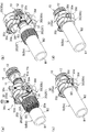
締め付け部材30の具体例として図1~図3に示される場合には、複数に分割された分割ホルダ30a,30bをボルトなどの締結部品30cで径方向へ互いに接近移動させることにより、弾性スリーブ20が径方向へ押圧されて縮径変形する分割タイプの圧縮手段を用いている。
詳しく説明すると、図3(a)~(d)に示されるように、分割タイプの圧縮手段は、径方向へ分割された複数の分割ホルダ30a,30bと、複数の分割ホルダ30a,30bを径方向へ接近移動させる締結部品30cと、を備えている。締結部品30cによる複数の分割ホルダ30a,30bの接近移動で、弾性スリーブ20を縮径変形させている。
図示例の場合には、複数の分割ホルダ30a,30bが円筒体を径方向へ二分割して対称形状に形成され、分割ホルダ30a,30b同士の周端部30dに亘り、ボルトのねじ部品などからなる締結部品30cを挿通して回転操作することにより、分割ホルダ30a,30b同士が径方向へ接近移動するように構成されている。
さらに図示例の場合には、複数の分割ホルダ30a,30bの周端部30dに亘って弾性スリーブ20のスリーブ外面20bと径方向へ対向するように設けられるストッパー部30eを備える。ストッパー部30eは、締結部品30cによる複数の分割ホルダ30a,30bの接近移動に伴って縮径変形した弾性スリーブ20の肉余り部位(図示しない)と径方向へ当接するガイド面30fを有している。これにより、複数の分割ホルダ30a,30bの接近移動で弾性スリーブ20の縮径変形に伴い、弾性スリーブ20のスリーブ外面20bの肉余り部位が、周方向へ隣り合う複数の分割ホルダ30a,30bの周端部30dの間に向け膨出しようとしても、スリーブ外面20bの肉余り部位の外側からストッパー部30eのガイド面30fが径方向へ当接することで、スリーブ外面20bの肉余り部位の膨出を抑制している。
このため、複数の分割ホルダ30a,30bの周端部30dの間にスリーブ外面20bの肉余り部位が入り込まず、周方向へ誘導され、噛み込みを防止して複数の分割ホルダ30a,30bを締結部品30cで締め切る(完全に締める)ことが可能にしている。
また、その他の例として図示しないが、複数の分割ホルダ30a,30bとして円筒体を三分割か又は四分割か若しくはそれ以上に分割して、それぞれを締結部品30cで複数の径方向へ接近移動させることなどの変更が可能である。 In the case shown in FIGS. 1 to 3 as a specific example of the tighteningmember 30, the elastic sleeve 20 is obtained by moving the divided holders 30a and 30b, which are divided into a plurality of parts, toward each other in the radial direction with a fastening component 30c such as a bolt. Uses a split type compression means that is pressed in the radial direction and deforms by reducing the diameter.
More specifically, as shown in FIGS. 3(a) to 3(d), the split type compression means has a plurality of split holders 30a and 30b that are split in the radial direction and a plurality of split holders 30a and 30b. And a fastening component 30c that moves closer to each other in the direction. The elastic sleeve 20 is contracted and deformed by the approaching movement of the plurality of divided holders 30a and 30b by the fastening component 30c.
In the case of the illustrated example, a plurality of split holders 30a and 30b are formed in a symmetrical shape by radially dividing the cylindrical body into two parts, and extend over the peripheral end portion 30d of the split holders 30a and 30b, such as a screw part of a bolt. The holder holders 30a and 30b are configured to be moved closer to each other in the radial direction by inserting and rotating the fastening component 30c.
Further, in the case of the illustrated example, astopper portion 30e provided so as to radially face the outer surface 20b of the elastic sleeve 20 over the peripheral end portions 30d of the plurality of divided holders 30a and 30b is provided. The stopper portion 30e has a guide surface 30f that comes into radial contact with a surplus portion (not shown) of the elastic sleeve 20 that has been reduced in diameter due to the approaching movement of the plurality of divided holders 30a and 30b by the fastening component 30c. There is. As a result, as the plurality of split holders 30a, 30b move closer to each other and the elastic sleeve 20 shrinks and deforms, the surplus portion of the outer surface 20b of the elastic sleeve 20 has a plurality of circumferentially adjacent split holders 30a, 30b. Even if an attempt is made to bulge between the peripheral end portions 30d, the guide surface 30f of the stopper portion 30e comes into radial contact with the outer surface of the excessively thickened portion of the sleeve outer surface 20b, so that the excessively thickened portion of the outer sleeve surface 20b swells. Is suppressed.
Therefore, the excess portion of the sleeveouter surface 20b does not enter between the peripheral end portions 30d of the plurality of divided holders 30a and 30b, but is guided in the circumferential direction to prevent the bite from being caught, and the plurality of divided holders 30a and 30b are fastened. It is possible to complete (completely tighten) with the component 30c.
Although not shown as another example, a cylindrical body is divided into three or four or more as a plurality of division holders 30a and 30b, and each of them is moved closer to a plurality of radial directions by a fastening component 30c. Things can be changed.
詳しく説明すると、図3(a)~(d)に示されるように、分割タイプの圧縮手段は、径方向へ分割された複数の分割ホルダ30a,30bと、複数の分割ホルダ30a,30bを径方向へ接近移動させる締結部品30cと、を備えている。締結部品30cによる複数の分割ホルダ30a,30bの接近移動で、弾性スリーブ20を縮径変形させている。
図示例の場合には、複数の分割ホルダ30a,30bが円筒体を径方向へ二分割して対称形状に形成され、分割ホルダ30a,30b同士の周端部30dに亘り、ボルトのねじ部品などからなる締結部品30cを挿通して回転操作することにより、分割ホルダ30a,30b同士が径方向へ接近移動するように構成されている。
さらに図示例の場合には、複数の分割ホルダ30a,30bの周端部30dに亘って弾性スリーブ20のスリーブ外面20bと径方向へ対向するように設けられるストッパー部30eを備える。ストッパー部30eは、締結部品30cによる複数の分割ホルダ30a,30bの接近移動に伴って縮径変形した弾性スリーブ20の肉余り部位(図示しない)と径方向へ当接するガイド面30fを有している。これにより、複数の分割ホルダ30a,30bの接近移動で弾性スリーブ20の縮径変形に伴い、弾性スリーブ20のスリーブ外面20bの肉余り部位が、周方向へ隣り合う複数の分割ホルダ30a,30bの周端部30dの間に向け膨出しようとしても、スリーブ外面20bの肉余り部位の外側からストッパー部30eのガイド面30fが径方向へ当接することで、スリーブ外面20bの肉余り部位の膨出を抑制している。
このため、複数の分割ホルダ30a,30bの周端部30dの間にスリーブ外面20bの肉余り部位が入り込まず、周方向へ誘導され、噛み込みを防止して複数の分割ホルダ30a,30bを締結部品30cで締め切る(完全に締める)ことが可能にしている。
また、その他の例として図示しないが、複数の分割ホルダ30a,30bとして円筒体を三分割か又は四分割か若しくはそれ以上に分割して、それぞれを締結部品30cで複数の径方向へ接近移動させることなどの変更が可能である。 In the case shown in FIGS. 1 to 3 as a specific example of the tightening
More specifically, as shown in FIGS. 3(a) to 3(d), the split type compression means has a plurality of
In the case of the illustrated example, a plurality of
Further, in the case of the illustrated example, a
Therefore, the excess portion of the sleeve
Although not shown as another example, a cylindrical body is divided into three or four or more as a plurality of
このような本発明の実施形態に係る管継手Aによると、図1(b)に示される締め付け部材30により弾性スリーブ20を縮径変形させた締め付け状態で、ニップル11の外周面11aと、弾性スリーブ20のスリーブ内面20aとの間に可撓管B(接続端部Ba)が径方向へ挟み込まれる。
これにより、可撓管B(接続端部Ba)がニップル11に対して軸方向へ抜け不能に挟持される。特にニップル11の大径円筒面11bと弾性スリーブ20の円筒内面23との間では、両者の挟み込みにより可撓管B(接続端部Baの一部)が径方向へ圧縮変形されて挟持部位Bbとなる。
この締め付け状態で可撓管Bの使用などにより図1(b)の二点鎖線に示されるように、可撓管B(接続端部Baを除いた部分)がニップル11及び弾性スリーブ20に対し径方向へ曲がった際には、挟持部位Bbと隣り合う不挟持部位Bcが、部分的に径方向へ屈曲変形すると同時に軸方向へも伸縮変形する。
このため、挟持部位Bbと不挟持部位Bcの境界部位には、屈曲変形や伸縮変形に伴う負荷が集中的にかかってストレス(圧力)が蓄積される。このような状況で可撓管Bがシリコーンゴムなどの柔らかい材料からなる場合には、僅かな切れ目が入ると簡単に破断してしまう。
この状況であっても、挟持部位Bbの内表面B1を大径円筒面11bと平滑状に圧接させることにより、可撓管B(接続端部Baを除いた部分)の屈曲変形や伸縮変形に伴って、挟持部位Bbを構成する材料が、大径円筒面11bに沿って不挟持部位Bcへ向けスムーズに移動可能となって負荷が分散する。
このため、挟持部位Bbから不挟持部位Bcへの構成材料の移動量が多くなるとストレスフリーとなって、挟持部位Bbと不挟持部位Bcの境界部位に切れ目が発生しない。
したがって、シリコーンゴムなどの柔らかい材料からなる可撓管Bであっても、可撓管Bの曲げに伴い切れず長期に亘って可撓管Bを抜け止めすることができる。
その結果、ニップルの竹の子状突起とスリーブの周突起との間にホースを径方向へ挟み込んで締め付ける従来のものに比べ、可撓管Bの切れによる破裂防止機能と可撓管Bの抜け防止機能を同時に併せ持つことができ、長期に亘って安定した可撓管Bの配管接続が持続されるとともに、流体漏れなどの事故の発生を防止できて、安全性及び経済性に優れる。 According to the pipe joint A according to the embodiment of the present invention, theelastic sleeve 20 is compressed and deformed by the tightening member 30 shown in FIG. The flexible tube B (connection end portion Ba) is radially sandwiched between the sleeve 20 and the sleeve inner surface 20a.
As a result, the flexible tube B (connection end portion Ba) is sandwiched in thenipple 11 so as not to come off in the axial direction. In particular, between the large-diameter cylindrical surface 11b of the nipple 11 and the cylindrical inner surface 23 of the elastic sleeve 20, the flexible tube B (a part of the connecting end portion Ba) is compressed and deformed in the radial direction due to the sandwiching of the both, and the sandwiching portion Bb. Becomes
When the flexible tube B is used in this tightened state, the flexible tube B (the portion excluding the connecting end portion Ba) is attached to thenipple 11 and the elastic sleeve 20 as shown by the chain double-dashed line in FIG. When bent in the radial direction, the non-sandwiched portion Bc adjacent to the sandwiched portion Bb is partially bent and deformed in the radial direction, and at the same time, is also stretched and deformed in the axial direction.
For this reason, stress (pressure) is accumulated in the boundary portion between the sandwiched portion Bb and the non-sandwiched portion Bc due to the concentrated load due to the bending deformation and the elastic deformation. In such a situation, when the flexible tube B is made of a soft material such as silicone rubber, it is easily broken if a slight break is made.
Even in this situation, the flexible tube B (the portion excluding the connection end portion Ba) can be bent or expanded/contracted by pressing the inner surface B1 of the sandwiched portion Bb against the large-diametercylindrical surface 11b in a smooth manner. Along with this, the material forming the sandwiched portion Bb can move smoothly along the large-diameter cylindrical surface 11b toward the non-sandwiched portion Bc, and the load is dispersed.
Therefore, when the amount of movement of the constituent material from the sandwiched portion Bb to the non-sandwiched portion Bc increases, the material becomes stress-free, and no break occurs at the boundary portion between the sandwiched portion Bb and the non-sandwiched portion Bc.
Therefore, even if the flexible tube B is made of a soft material such as silicone rubber, the flexible tube B can be prevented from slipping out for a long period of time without being broken as the flexible tube B is bent.
As a result, as compared with the conventional one in which the hose is radially clamped between the bamboo shoot-like projection of the nipple and the circumferential projection of the sleeve, the function of preventing the flexible tube B from bursting due to breakage and the function of preventing the flexible tube B from coming off. Simultaneously, the stable flexible pipe B connection can be maintained for a long period of time, an accident such as fluid leakage can be prevented, and safety and economy are excellent.
これにより、可撓管B(接続端部Ba)がニップル11に対して軸方向へ抜け不能に挟持される。特にニップル11の大径円筒面11bと弾性スリーブ20の円筒内面23との間では、両者の挟み込みにより可撓管B(接続端部Baの一部)が径方向へ圧縮変形されて挟持部位Bbとなる。
この締め付け状態で可撓管Bの使用などにより図1(b)の二点鎖線に示されるように、可撓管B(接続端部Baを除いた部分)がニップル11及び弾性スリーブ20に対し径方向へ曲がった際には、挟持部位Bbと隣り合う不挟持部位Bcが、部分的に径方向へ屈曲変形すると同時に軸方向へも伸縮変形する。
このため、挟持部位Bbと不挟持部位Bcの境界部位には、屈曲変形や伸縮変形に伴う負荷が集中的にかかってストレス(圧力)が蓄積される。このような状況で可撓管Bがシリコーンゴムなどの柔らかい材料からなる場合には、僅かな切れ目が入ると簡単に破断してしまう。
この状況であっても、挟持部位Bbの内表面B1を大径円筒面11bと平滑状に圧接させることにより、可撓管B(接続端部Baを除いた部分)の屈曲変形や伸縮変形に伴って、挟持部位Bbを構成する材料が、大径円筒面11bに沿って不挟持部位Bcへ向けスムーズに移動可能となって負荷が分散する。
このため、挟持部位Bbから不挟持部位Bcへの構成材料の移動量が多くなるとストレスフリーとなって、挟持部位Bbと不挟持部位Bcの境界部位に切れ目が発生しない。
したがって、シリコーンゴムなどの柔らかい材料からなる可撓管Bであっても、可撓管Bの曲げに伴い切れず長期に亘って可撓管Bを抜け止めすることができる。
その結果、ニップルの竹の子状突起とスリーブの周突起との間にホースを径方向へ挟み込んで締め付ける従来のものに比べ、可撓管Bの切れによる破裂防止機能と可撓管Bの抜け防止機能を同時に併せ持つことができ、長期に亘って安定した可撓管Bの配管接続が持続されるとともに、流体漏れなどの事故の発生を防止できて、安全性及び経済性に優れる。 According to the pipe joint A according to the embodiment of the present invention, the
As a result, the flexible tube B (connection end portion Ba) is sandwiched in the
When the flexible tube B is used in this tightened state, the flexible tube B (the portion excluding the connecting end portion Ba) is attached to the
For this reason, stress (pressure) is accumulated in the boundary portion between the sandwiched portion Bb and the non-sandwiched portion Bc due to the concentrated load due to the bending deformation and the elastic deformation. In such a situation, when the flexible tube B is made of a soft material such as silicone rubber, it is easily broken if a slight break is made.
Even in this situation, the flexible tube B (the portion excluding the connection end portion Ba) can be bent or expanded/contracted by pressing the inner surface B1 of the sandwiched portion Bb against the large-diameter
Therefore, when the amount of movement of the constituent material from the sandwiched portion Bb to the non-sandwiched portion Bc increases, the material becomes stress-free, and no break occurs at the boundary portion between the sandwiched portion Bb and the non-sandwiched portion Bc.
Therefore, even if the flexible tube B is made of a soft material such as silicone rubber, the flexible tube B can be prevented from slipping out for a long period of time without being broken as the flexible tube B is bent.
As a result, as compared with the conventional one in which the hose is radially clamped between the bamboo shoot-like projection of the nipple and the circumferential projection of the sleeve, the function of preventing the flexible tube B from bursting due to breakage and the function of preventing the flexible tube B from coming off. Simultaneously, the stable flexible pipe B connection can be maintained for a long period of time, an accident such as fluid leakage can be prevented, and safety and economy are excellent.
特に、スリーブ内面20aにおいて円筒内面23を、可撓管Bの外表面B2に向け径方向へ部分的に突出して形成することが好ましい。
この場合には、図1(b)に示される締め付け状態で、スリーブ内面20aから部分的に突出した円筒内面23が、可撓管Bの外表面B2に食い込むことにより、円筒内面23で押圧された可撓管Bの挟持部位Bbの内表面B1を、ニップル11の大径円筒面11bに密着させる。
したがって、ニップル11の大径円筒面11bに対する可撓管Bの抜け強度と気密性を向上させることができる。
その結果、可撓管Bの抜け防止機能が強化され、長期に亘る配管接続の更なる安定持続が可能になり、流体漏れなどの事故の発生を更に防止できて、更に安全性の向上が図れる。 In particular, it is preferable that the cylindricalinner surface 23 of the sleeve inner surface 20a is formed so as to partially project in the radial direction toward the outer surface B2 of the flexible tube B.
In this case, in the tightened state shown in FIG. 1B, the cylindricalinner surface 23 that partially protrudes from the sleeve inner surface 20a bites into the outer surface B2 of the flexible tube B and is pressed by the cylindrical inner surface 23. The inner surface B1 of the sandwiching portion Bb of the flexible tube B is brought into close contact with the large-diameter cylindrical surface 11b of the nipple 11.
Therefore, the pull-out strength and airtightness of the flexible tube B with respect to the large-diametercylindrical surface 11b of the nipple 11 can be improved.
As a result, the function of preventing the flexible tube B from coming off is strengthened, more stable and stable pipe connection can be maintained for a long period of time, accidents such as fluid leakage can be further prevented, and safety can be further improved. ..
この場合には、図1(b)に示される締め付け状態で、スリーブ内面20aから部分的に突出した円筒内面23が、可撓管Bの外表面B2に食い込むことにより、円筒内面23で押圧された可撓管Bの挟持部位Bbの内表面B1を、ニップル11の大径円筒面11bに密着させる。
したがって、ニップル11の大径円筒面11bに対する可撓管Bの抜け強度と気密性を向上させることができる。
その結果、可撓管Bの抜け防止機能が強化され、長期に亘る配管接続の更なる安定持続が可能になり、流体漏れなどの事故の発生を更に防止できて、更に安全性の向上が図れる。 In particular, it is preferable that the cylindrical
In this case, in the tightened state shown in FIG. 1B, the cylindrical
Therefore, the pull-out strength and airtightness of the flexible tube B with respect to the large-diameter
As a result, the function of preventing the flexible tube B from coming off is strengthened, more stable and stable pipe connection can be maintained for a long period of time, accidents such as fluid leakage can be further prevented, and safety can be further improved. ..
さらに、ニップル11の外周面11aが、大径円筒面11bと軸方向へ隣接して設けられる環状溝11cを有し、スリーブ内面20aが、可撓管Bを挟んで環状溝11cと径方向へ対向して設けられる環状リブ24を有することが好ましい。
この場合には、図1(b)に示される締め付け状態で、スリーブ内面20aの環状リブ24が可撓管Bの外表面B2に食い込むことにより、環状リブ24で押圧された可撓管Bの挟持部位Bbの内表面B1を、ニップル11の環状溝11cに嵌入させる。
このため、可撓管Bの内表面B1が大径円筒面11b及び環状溝11cとそれぞれ軸方向へ凹凸嵌合して、可撓管Bが軸方向へ位置決めされる。
したがって、可撓管Bをより軸方向へ抜け不能に押圧することができる。
その結果、可撓管Bの抜け防止機能がより強化され、長期に亘る配管接続の更なる安定持続が可能で、流体漏れなどの事故の発生防止と安全性の更なる向上が図れる。 Further, the outerperipheral surface 11a of the nipple 11 has an annular groove 11c provided axially adjacent to the large-diameter cylindrical surface 11b, and the sleeve inner surface 20a extends radially with the annular groove 11c with the flexible tube B interposed therebetween. It is preferable to have the annular ribs 24 provided so as to face each other.
In this case, theannular rib 24 of the sleeve inner surface 20a bites into the outer surface B2 of the flexible tube B in the tightened state shown in FIG. The inner surface B1 of the holding part Bb is fitted into the annular groove 11c of the nipple 11.
Therefore, the inner surface B1 of the flexible tube B is fitted into the large-diametercylindrical surface 11b and the annular groove 11c in the axial direction, respectively, and the flexible tube B is axially positioned.
Therefore, the flexible tube B can be pressed in the axial direction so as not to come off.
As a result, the function of preventing the flexible tube B from coming off is further strengthened, the pipe connection can be maintained more stably for a long period of time, accidents such as fluid leakage can be prevented, and safety can be further improved.
この場合には、図1(b)に示される締め付け状態で、スリーブ内面20aの環状リブ24が可撓管Bの外表面B2に食い込むことにより、環状リブ24で押圧された可撓管Bの挟持部位Bbの内表面B1を、ニップル11の環状溝11cに嵌入させる。
このため、可撓管Bの内表面B1が大径円筒面11b及び環状溝11cとそれぞれ軸方向へ凹凸嵌合して、可撓管Bが軸方向へ位置決めされる。
したがって、可撓管Bをより軸方向へ抜け不能に押圧することができる。
その結果、可撓管Bの抜け防止機能がより強化され、長期に亘る配管接続の更なる安定持続が可能で、流体漏れなどの事故の発生防止と安全性の更なる向上が図れる。 Further, the outer
In this case, the
Therefore, the inner surface B1 of the flexible tube B is fitted into the large-diameter
Therefore, the flexible tube B can be pressed in the axial direction so as not to come off.
As a result, the function of preventing the flexible tube B from coming off is further strengthened, the pipe connection can be maintained more stably for a long period of time, accidents such as fluid leakage can be prevented, and safety can be further improved.
また、スリーブ内面20aから可撓管Bの外表面B2に向け径方向へ突出する円筒内面23の突出量を、環状リブ24の突出量よりも小さく形成することが好ましい。
この場合には、図1(b)に示される締め付け状態で、可撓管Bの外表面B2に対する円筒内面23の食い込み量が、可撓管Bの外表面B2に対する環状リブ24の食い込み量よりも少ない。
このため、可撓管Bの使用などにより図1(b)の二点鎖線に示されるように、可撓管B(接続端部Baを除いた部分)がニップル11及び弾性スリーブ20に対し径方向へ曲がったとしても、スリーブ内面20aから突出した円筒内面23の食い込みにより、可撓管Bの外表面B2に切れ目が発生し難くなる。
したがって、可撓管Bの曲げに伴う切れを確実に防止することができる。
その結果、可撓管Bの切れによる破裂防止機能が強化され、長期に亘る配管接続の安定性と流体漏れなどの事故の発生防止と安全性を共に向上できる。 In addition, it is preferable that the cylindricalinner surface 23 protruding radially from the sleeve inner surface 20a toward the outer surface B2 of the flexible tube B is formed to have a smaller projection amount than the annular rib 24.
In this case, in the tightened state shown in FIG. 1B, the biting amount of the cylindricalinner surface 23 with respect to the outer surface B2 of the flexible tube B is larger than the biting amount of the annular rib 24 with respect to the outer surface B2 of the flexible tube B. Also few.
Therefore, due to the use of the flexible tube B or the like, the flexible tube B (the portion excluding the connecting end portion Ba) is larger than thenipple 11 and the elastic sleeve 20 as shown by the chain double-dashed line in FIG. Even if it bends in the direction, due to the biting of the cylindrical inner surface 23 protruding from the sleeve inner surface 20a, a break is unlikely to occur on the outer surface B2 of the flexible tube B.
Therefore, it is possible to reliably prevent breakage of the flexible tube B due to bending.
As a result, the function of preventing rupture due to the break of the flexible tube B is strengthened, and it is possible to improve both stability of piping connection for a long period of time, prevention of accident such as fluid leakage, and safety.
この場合には、図1(b)に示される締め付け状態で、可撓管Bの外表面B2に対する円筒内面23の食い込み量が、可撓管Bの外表面B2に対する環状リブ24の食い込み量よりも少ない。
このため、可撓管Bの使用などにより図1(b)の二点鎖線に示されるように、可撓管B(接続端部Baを除いた部分)がニップル11及び弾性スリーブ20に対し径方向へ曲がったとしても、スリーブ内面20aから突出した円筒内面23の食い込みにより、可撓管Bの外表面B2に切れ目が発生し難くなる。
したがって、可撓管Bの曲げに伴う切れを確実に防止することができる。
その結果、可撓管Bの切れによる破裂防止機能が強化され、長期に亘る配管接続の安定性と流体漏れなどの事故の発生防止と安全性を共に向上できる。 In addition, it is preferable that the cylindrical
In this case, in the tightened state shown in FIG. 1B, the biting amount of the cylindrical
Therefore, due to the use of the flexible tube B or the like, the flexible tube B (the portion excluding the connecting end portion Ba) is larger than the
Therefore, it is possible to reliably prevent breakage of the flexible tube B due to bending.
As a result, the function of preventing rupture due to the break of the flexible tube B is strengthened, and it is possible to improve both stability of piping connection for a long period of time, prevention of accident such as fluid leakage, and safety.
なお、前示の実施形態では、締め付け部材30の具体例として分割タイプの圧縮手段を用いたが、これに限定されず、分割タイプの圧縮手段に代えて特開2001-193876号に記載の袋ナットを用いるなど、他の締め付け手段に変更してもよい。
In the embodiment shown above, the split type compression means is used as a specific example of the tightening member 30, but the invention is not limited to this, and instead of the split type compression means, the bag described in Japanese Patent Laid-Open No. 2001-193876. You may change to another fastening means, such as using a nut.
A 管継手 11 ニップル
11a 外周面 11b 大径円筒面
11c 環状溝 20 弾性スリーブ
20a スリーブ内面 23 円筒内面
24 環状リブ 30 締め付け部材
31 押圧部 B 可撓管
B1 内表面 B2 外表面
S 可撓管の挿入空間 A pipe joint 11nipple 11a outer peripheral surface 11b large diameter cylindrical surface 11c annular groove 20 elastic sleeve 20a sleeve inner surface 23 cylindrical inner surface 24 annular rib 30 tightening member 31 pressing portion B flexible tube B1 inner surface B2 outer surface S insertion of flexible tube space
11a 外周面 11b 大径円筒面
11c 環状溝 20 弾性スリーブ
20a スリーブ内面 23 円筒内面
24 環状リブ 30 締め付け部材
31 押圧部 B 可撓管
B1 内表面 B2 外表面
S 可撓管の挿入空間 A pipe joint 11
Claims (4)
- 可撓管の挿入空間に沿って設けられる円筒状のニップルと、
前記ニップルの外周面との間に前記可撓管の前記挿入空間を径方向へ挟み込むように設けられた径方向へ変形可能な弾性スリーブと、
前記弾性スリーブの外側に設けられて前記弾性スリーブを前記ニップルに向け押し付ける押圧部を有する締め付け部材と、を備え、
前記ニップルは、前記外周面の軸方向先端に前記可撓管の内表面と径方向へ対向して圧接する軸方向へ平滑な大径円筒面を有し、
前記弾性スリーブは、前記可撓管を挟んで前記ニップルの前記大径円筒面と径方向へ対向するスリーブ内面に前記可撓管の外表面と圧接する軸方向へ平滑な円筒内面を有することを特徴とする管継手。 A cylindrical nipple provided along the insertion space of the flexible tube,
A radially deformable elastic sleeve that is provided so as to sandwich the insertion space of the flexible tube in the radial direction between the outer peripheral surface of the nipple and the outer surface.
A tightening member provided on the outside of the elastic sleeve and having a pressing portion for pressing the elastic sleeve toward the nipple,
The nipple has an axially smooth large-diameter cylindrical surface that is in pressure contact with the inner surface of the flexible tube in a radial direction at the axial tip end of the outer peripheral surface,
The elastic sleeve may have an axially smooth cylindrical inner surface that is in pressure contact with an outer surface of the flexible tube on an inner surface of the sleeve that radially faces the large-diameter cylindrical surface of the nipple with the flexible tube interposed therebetween. A characteristic pipe joint. - 前記スリーブ内面において前記円筒内面が、前記可撓管の前記外表面に向け径方向へ部分的に突出して形成されることを特徴とする請求項1記載の管継手。 The pipe joint according to claim 1, wherein the inner surface of the cylinder in the inner surface of the sleeve is formed so as to partially project in the radial direction toward the outer surface of the flexible tube.
- 前記ニップルの前記外周面が、前記大径円筒面と軸方向へ隣接して設けられる環状溝を有し、
前記スリーブ内面が、前記可撓管を挟んで前記環状溝と径方向へ対向して設けられる環状リブを有することを特徴とする請求項1又は2記載の管継手。 The outer peripheral surface of the nipple has an annular groove provided axially adjacent to the large diameter cylindrical surface,
The pipe joint according to claim 1 or 2, wherein the inner surface of the sleeve has an annular rib provided radially opposite the annular groove with the flexible tube interposed therebetween. - 前記スリーブ内面から前記可撓管の前記外表面に向け径方向へ突出する前記円筒内面の突出量が、前記環状リブの突出量よりも小さく形成されることを特徴とする請求項3記載の管継手。 4. The pipe according to claim 3, wherein an amount of protrusion of the inner surface of the cylinder radially protruding from the inner surface of the sleeve toward the outer surface of the flexible tube is smaller than an amount of protrusion of the annular rib. Fittings.
Priority Applications (3)
| Application Number | Priority Date | Filing Date | Title |
|---|---|---|---|
| EP20754138.4A EP3926224A4 (en) | 2019-02-12 | 2020-02-07 | Pipe joint |
| US17/425,097 US20220107042A1 (en) | 2019-02-12 | 2020-02-07 | Hose joint |
| CN202080011796.4A CN113383186A (en) | 2019-02-12 | 2020-02-07 | Pipe joint |
Applications Claiming Priority (2)
| Application Number | Priority Date | Filing Date | Title |
|---|---|---|---|
| JP2019022779A JP6798713B2 (en) | 2019-02-12 | 2019-02-12 | Pipe fitting |
| JP2019-022779 | 2019-02-12 |
Publications (1)
| Publication Number | Publication Date |
|---|---|
| WO2020166516A1 true WO2020166516A1 (en) | 2020-08-20 |
Family
ID=72043858
Family Applications (1)
| Application Number | Title | Priority Date | Filing Date |
|---|---|---|---|
| PCT/JP2020/004879 WO2020166516A1 (en) | 2019-02-12 | 2020-02-07 | Pipe joint |
Country Status (5)
| Country | Link |
|---|---|
| US (1) | US20220107042A1 (en) |
| EP (1) | EP3926224A4 (en) |
| JP (1) | JP6798713B2 (en) |
| CN (1) | CN113383186A (en) |
| WO (1) | WO2020166516A1 (en) |
Families Citing this family (1)
| Publication number | Priority date | Publication date | Assignee | Title |
|---|---|---|---|---|
| JP2022108189A (en) * | 2021-01-12 | 2022-07-25 | ニッタ株式会社 | Hose joint |
Citations (5)
| Publication number | Priority date | Publication date | Assignee | Title |
|---|---|---|---|---|
| JP2001193876A (en) | 2000-01-12 | 2001-07-17 | Nippon Flex Kk | Hose connector |
| JP2009270622A (en) * | 2008-05-07 | 2009-11-19 | Toyox Co Ltd | Pipe joint |
| US20100102551A1 (en) * | 2008-10-27 | 2010-04-29 | Dennis Zeiber | Hose coupling |
| JP2011102605A (en) * | 2009-11-10 | 2011-05-26 | Toyox Co Ltd | Hose connector |
| JP2015517067A (en) * | 2012-04-17 | 2015-06-18 | オプシェストヴォ サグラニチェノイ オトヴェトストヴェンノスチユ “グルーパ ポリメルテプロ” | Polymer fitting assembly |
Family Cites Families (13)
| Publication number | Priority date | Publication date | Assignee | Title |
|---|---|---|---|---|
| US3222091A (en) * | 1962-08-30 | 1965-12-07 | Dixon Valve & Coupling Co | Pressure responsive fluid tight hose coupling |
| GB2022744B (en) * | 1978-06-06 | 1982-09-02 | Duffield Ltd F | Hose and fitting |
| JPS5962388U (en) * | 1982-10-16 | 1984-04-24 | 小杉 一雄 | pipe fittings |
| US4653779A (en) * | 1986-03-17 | 1987-03-31 | Dayco Products, Inc. | Hose coupling and method of making the same |
| DE3627274A1 (en) * | 1986-08-12 | 1988-02-18 | Widenmann Max Armaturen | HOSE COVER |
| US5267758A (en) * | 1991-07-18 | 1993-12-07 | The Gates Rubber Company | Ferrule coupling having a C-shaped insert |
| AT8016U1 (en) * | 2001-08-13 | 2005-12-15 | Geiser Friedrich | HOSE CLAMP DEVICE |
| JP2011102606A (en) * | 2009-11-10 | 2011-05-26 | Toyox Co Ltd | Hose connector |
| DE102010038170A1 (en) * | 2009-11-12 | 2011-08-25 | Reckzeh, Manfred, 63457 | Pipe-pressing couplings, in particular for the compression of multilayer pipes, and method for producing a pipe-press coupling |
| WO2011155436A1 (en) * | 2010-06-11 | 2011-12-15 | 東拓工業株式会社 | Pipe end joint |
| IN2014CN03672A (en) * | 2011-10-20 | 2015-07-03 | Toyox Kk | |
| DE202012101020U1 (en) * | 2012-03-22 | 2012-07-10 | Schwer Fittings Gmbh | Device for connecting a hose end |
| JP5953586B2 (en) * | 2014-04-11 | 2016-07-20 | 株式会社トヨックス | Pipe fitting |
-
2019
- 2019-02-12 JP JP2019022779A patent/JP6798713B2/en active Active
-
2020
- 2020-02-07 CN CN202080011796.4A patent/CN113383186A/en active Pending
- 2020-02-07 EP EP20754138.4A patent/EP3926224A4/en active Pending
- 2020-02-07 WO PCT/JP2020/004879 patent/WO2020166516A1/en unknown
- 2020-02-07 US US17/425,097 patent/US20220107042A1/en active Pending
Patent Citations (5)
| Publication number | Priority date | Publication date | Assignee | Title |
|---|---|---|---|---|
| JP2001193876A (en) | 2000-01-12 | 2001-07-17 | Nippon Flex Kk | Hose connector |
| JP2009270622A (en) * | 2008-05-07 | 2009-11-19 | Toyox Co Ltd | Pipe joint |
| US20100102551A1 (en) * | 2008-10-27 | 2010-04-29 | Dennis Zeiber | Hose coupling |
| JP2011102605A (en) * | 2009-11-10 | 2011-05-26 | Toyox Co Ltd | Hose connector |
| JP2015517067A (en) * | 2012-04-17 | 2015-06-18 | オプシェストヴォ サグラニチェノイ オトヴェトストヴェンノスチユ “グルーパ ポリメルテプロ” | Polymer fitting assembly |
Non-Patent Citations (1)
| Title |
|---|
| See also references of EP3926224A4 |
Also Published As
| Publication number | Publication date |
|---|---|
| EP3926224A4 (en) | 2022-10-26 |
| US20220107042A1 (en) | 2022-04-07 |
| CN113383186A (en) | 2021-09-10 |
| EP3926224A1 (en) | 2021-12-22 |
| JP2020133640A (en) | 2020-08-31 |
| JP6798713B2 (en) | 2020-12-09 |
Similar Documents
| Publication | Publication Date | Title |
|---|---|---|
| JP5557221B2 (en) | Pipe fitting | |
| WO2013115044A1 (en) | Pipe joint | |
| WO2015029815A1 (en) | Tube joint | |
| WO2015156198A1 (en) | Pipe fitting | |
| WO2020166516A1 (en) | Pipe joint | |
| JP6078857B2 (en) | Pipe fitting | |
| JP2015203439A5 (en) | ||
| WO2011058877A1 (en) | Hose connector | |
| JP2020133640A5 (en) | ||
| WO2021220457A1 (en) | Sleeve for pipe coupling and pipe coupling provided with said sleeve for pipe coupling | |
| JP6765729B2 (en) | Sleeve for fittings | |
| JP5849261B2 (en) | Pipe fitting | |
| JP6010831B2 (en) | Pipe joint structure | |
| JP2013040645A (en) | Pipe joint | |
| JP5273493B2 (en) | Band set for pipe connection and attachment for tightening band | |
| TWI809270B (en) | Sleeves for pipe joints | |
| JP5584378B1 (en) | Pipe fitting | |
| WO2023199769A1 (en) | Pipe joint and sleeve to be used for pipe joint | |
| JP5799326B2 (en) | Pipe fitting | |
| JP7100850B2 (en) | Pipe fittings | |
| JP6770753B2 (en) | Pipe fitting | |
| WO2013108679A1 (en) | Tube connection band set and fastening band attachment | |
| WO2023199770A1 (en) | Pipe joint | |
| JPS587180Y2 (en) | Soft pipe fitting device | |
| JP2017067097A (en) | Pipe fastening structure and pipe fastening tool |
Legal Events
| Date | Code | Title | Description |
|---|---|---|---|
| 121 | Ep: the epo has been informed by wipo that ep was designated in this application |
Ref document number: 20754138 Country of ref document: EP Kind code of ref document: A1 |
|
| NENP | Non-entry into the national phase |
Ref country code: DE |
|
| ENP | Entry into the national phase |
Ref document number: 2020754138 Country of ref document: EP Effective date: 20210913 |