WO2020166498A1 - ソケット - Google Patents
ソケット Download PDFInfo
- Publication number
- WO2020166498A1 WO2020166498A1 PCT/JP2020/004749 JP2020004749W WO2020166498A1 WO 2020166498 A1 WO2020166498 A1 WO 2020166498A1 JP 2020004749 W JP2020004749 W JP 2020004749W WO 2020166498 A1 WO2020166498 A1 WO 2020166498A1
- Authority
- WO
- WIPO (PCT)
- Prior art keywords
- heater
- floating
- contact
- socket
- inspected
- Prior art date
- Legal status (The legal status is an assumption and is not a legal conclusion. Google has not performed a legal analysis and makes no representation as to the accuracy of the status listed.)
- Ceased
Links
Images




Classifications
-
- G—PHYSICS
- G01—MEASURING; TESTING
- G01R—MEASURING ELECTRIC VARIABLES; MEASURING MAGNETIC VARIABLES
- G01R31/00—Arrangements for testing electric properties; Arrangements for locating electric faults; Arrangements for electrical testing characterised by what is being tested not provided for elsewhere
- G01R31/26—Testing of individual semiconductor devices
-
- H—ELECTRICITY
- H01—ELECTRIC ELEMENTS
- H01R—ELECTRICALLY-CONDUCTIVE CONNECTIONS; STRUCTURAL ASSOCIATIONS OF A PLURALITY OF MUTUALLY-INSULATED ELECTRICAL CONNECTING ELEMENTS; COUPLING DEVICES; CURRENT COLLECTORS
- H01R33/00—Coupling devices specially adapted for supporting apparatus and having one part acting as a holder providing support and electrical connection via a counterpart which is structurally associated with the apparatus, e.g. lamp holders; Separate parts thereof
- H01R33/74—Devices having four or more poles, e.g. holders for compact fluorescent lamps
- H01R33/76—Holders with sockets, clips, or analogous contacts adapted for axially-sliding engagement with parallely-arranged pins, blades, or analogous contacts on counterpart, e.g. electronic tube socket
Definitions
- the present disclosure relates to a socket used when inspecting the electrical characteristics of a member to be inspected.
- a socket has been used to electrically connect a member to be inspected and a wiring board when inspecting a member to be inspected such as an IC package (for example, a burn-in test).
- Patent Document 1 describes a socket in which a heater is provided in a socket body in which an IC package is housed, and an inspection is performed while the IC package is heated by the heater.
- the socket described in Patent Document 1 has a configuration in which a power line for supplying power to the heater is constantly connected to the heater, power is supplied to the heater even when the IC package is not housed in the socket body, for example.
- the heater may be heated.
- An object of the present disclosure is to provide a socket that can prevent a heater from being heated when a member to be inspected is not inspected.
- a socket according to an aspect of the present disclosure is provided with a socket main body, a contact pin supported by the socket main body, an upper part of the contact pin, a component to be inspected placed, and contact with the contact pin.
- a heater is provided between the socket body and the heater, which is heated by electric power supplied from a power source, and has a first mounting surface on which the heater is mounted.
- the upper end portion of the contact pin is positioned below the mounting surface in the vertical direction and the heater is moved in the vertical direction.
- the upper end is a socket that is in contact with the heater when the floating moves downward and is separated.
- the heater it is possible to prevent the heater from being heated when the member to be inspected is not inspected.
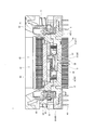
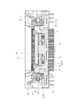
- FIG. 1 is a perspective view showing a socket according to an embodiment.
- FIG. 2 is a sectional view of the socket.
- FIG. 3 is a sectional view of the socket.
- FIG. 4 is a sectional view of the socket.
- FIG. 5 is a sectional view of the socket.
- FIG. 6 is a sectional view of the socket.
- FIG. 7 is a sectional view of the socket.
- the socket will be described assuming that the socket body is arranged on the lower side and the cover is arranged on the upper side of the socket body. That is, the direction from the socket body to the cover (upward direction in FIGS. 2 to 7) is the upward direction in the socket, and the direction from the cover to the socket body (downward direction in FIGS. 2 to 7) is the downward direction in the socket.
- the arrangement of the socket body and the cover is not limited to such arrangement.
- FIG. 1 is a perspective view showing a socket 1 according to the embodiment.
- FIG. 2 is a sectional view of the socket 1.
- FIG. 3 is a sectional view of the socket 1 and shows a sectional view different from that in FIG.
- the socket 1 is a device for accommodating the member to be inspected 2 and electrically connecting the housed member to be inspected 2 and a wiring board (not shown) attached to the lower side of the socket 1.
- the inspected member 2 is, for example, an electronic component such as an IC package.
- Various inspections are performed on the inspected member 2 housed in the socket 1 and electrically connected to the wiring board. For example, it is checked whether or not the inspected member 2 properly operates in the same environment as the actual use environment of the inspected member 2 or in an environment in which the load is higher than the actual use environment.
- the socket 1 has a socket body 10, a cover 20, a power supply pin 30 (an example of a “contact pin”), a floating 40, and a heater 50.
- the socket body 10 includes a bottom plate 11 and a frame body 12.
- the bottom plate 11 defines the outer shape of the socket body 10.
- a plurality of contact pins 60 are fixed to the bottom plate 11.
- the socket body 10 has the example in which the bottom plate 11 and the frame body 12 are separate bodies, but the bottom plate 11 and the frame body 12 may be integrally formed.
- the contact pin 60 is formed of a plate material having conductivity and elasticity.
- the contact pin 60 includes a fixed portion 61 which is press-fitted into the bottom plate 11 from the lateral direction to sandwich the bottom plate 11 from above and below, and a lead portion 62 which extends downward from the fixed portion 61 and is electrically connected to the wiring board. Have.
- the contact pin 60 is provided with an elastic portion 63 extending upward from the fixing portion 61, an upper contact portion 64 provided on the distal end side of the elastic portion 63 and contacting an upper surface of the terminal of the inspected member 2, and an upper contact portion.
- An extension portion 65 that extends further upward from the portion 64 and can be tilted outward by being pressed by a pressing surface 21 (described later) of the cover 20.
- the contact pin 60 has a lower contact portion 66 extending laterally and upward from the fixed portion 61 and contacting the lower surface of the terminal of the member 2 to be inspected.
- the terminal of the inspected member 2 is electrically connected to the contact pin 60 by being sandwiched between the upper contact portion 64 and the lower contact portion 66.
- a hole 13 is formed in the center of the bottom plate 11 so as to penetrate vertically.
- a fixing portion 31 (described later) of the power supply pin 30 is press-fitted into the hole 13.
- a mounting portion 14 that projects upward is provided at the center of the bottom plate 11. The function of the mounting unit 14 will be described later.
- the frame 12 is fixed to the upper surface of the bottom plate 11.
- the frame body 12 has an upper surface 15 facing the inspected member 2.
- the inner side surface that defines the opening of the frame body 12 functions as a guide surface of the floating 40.
- the cover 20 has a frame shape having an opening in the center.
- the cover 20 is arranged above the socket body 10.
- the cover 20 is urged by the spring 3 in a direction away from the socket body 10 (that is, upward).
- the cover 20 is vertically movable between an upper end position and a lower end position.
- the cover 20 has a pressing surface 21 that faces downward and inclines upward from the inside toward the outside. As described above, the pressing surface 21 presses the extension portion 65.
- the power supply pin 30 is formed of a plate material having conductivity and elasticity, like the contact pin 60 described above.
- the power supply pin 30 has a fixed portion 31 that is press-fitted into the hole 13 and fixed to the socket body 10, and a lead portion 32 that extends downward from the fixed portion 31 and that is electrically connected to the wiring board. ..
- the power supply pin 30 extends upwardly and laterally from the fixed portion 31 (an example of a “connecting portion”), and extends upward from the tip of the elastic portion 33 and is provided on the lower surface of the heater 50.
- the contact part 34 (an example of an "upper end part") which contacts. The upper end of the contact portion 34 is the upper end of the power supply pin 30.
- the floating 40 has a substantially rectangular shape in a plan view.
- the floating 40 is arranged above the central portion of the socket body 10.
- the floating 40 is biased by the spring 4 in a direction away from the socket body 10 (that is, upward).
- the floating 40 is vertically movable between an upper end position and a lower end position.
- the floating 40 is made of an insulating resin.
- the floating 40 has a main body 42 having a mounting surface 41 on which the heater 50 is mounted, and an engaging claw 43 protruding upward from the main body 42. The function of the engaging claw 43 will be described later.
- a hole 44, a hole 45, and a hole 46 penetrating in the vertical direction are formed in the main body 42.
- the mounting portion 14 of the socket body 10 is inserted into the hole 44.
- the contact portion 34 of the power supply pin 30 is inserted into the hole 45.
- the elastic portion 33 of the power supply pin 30 is inserted into the hole 46.
- the hole 44 and the hole 45 are partitioned by a wall 47 (an example of a “pressing portion”). As shown in FIG. 3, the contact surface 47a facing downward of the wall 47 is an arc surface.
- the socket 1 has a claw 5 that lowers the floating 40 by pressing the mounting surface 41 of the floating 40 downward in conjunction with the lowering of the cover 20. Therefore, the floating 40 descends in conjunction with the descent of the cover 20.
- the heater 50 has a substantially rectangular shape in a plan view.
- the main body of the member to be inspected 2 contacts the upper surface of the heater 50.
- the contact portion 34 of the power supply pin 30 can contact the lower surface of the heater 50.
- the upper surface of the mounting portion 14 of the socket body 10 and the lower surface of the heater 50 face each other with a gap.
- the heater 50 mounted on the mounting surface 41 of the floating 40 also descends, and the gap between the lower surface of the heater 50 and the contact portion 34 of the power supply pin 30 becomes smaller.
- the heater 50 is only mounted on the mounting surface 41 of the floating 40, and is not fixed to the floating 40. Therefore, after the lower surface of the heater 50 comes into contact with the contact portion 34 of the power supply pin 30, only the weight of the heater 50 is applied to the power supply pin 30.
- the elastic force of the elastic portion 33 of the power supply pin 30 is set to be larger than the pressure applied to the elastic portion 33 by the weight of the heater, the elastic portion 33 is not deformed by the weight of the heater. Therefore, the load on the contact portion 34 of the power supply pin 30 can be reduced.
- the lower surface of the heater 50 and the lower surface of the heater 50 contact the mounting portion 14 of the socket body 10, and the heater 50 is mounted on the mounting portion 14. At this time, a gap is formed between the lower surface of the heater 50 and the contact portion 34 of the power supply pin 30.
- the contact load on the contact portion 34 of the power supply pin 30 can be reduced except during the continuity inspection. Further, when the heater 50 is placed on the placing portion 14 of the socket body 10, a gap is created between the lower surface of the heater 50 and the contact portion 34 of the power supply pin 30, so that the power supply pin 30 rotates. It is possible to avoid rubbing due to the contact between the contact portion 34 and the lower surface of the heater 50. As a result, the load on the power supply pin can be reduced.
- the contact surface 47a facing downward of the wall 47 of the floating 40 is an arc surface. Therefore, when the floating 40 descends, the contact point between the contact surface 47a and the elastic portion 33 of the power supply pin 30 moves. Therefore, the load on the floating 40 and the power supply pin 30 can be reduced as compared with the case where the contact surface 47a and the elastic portion 33 contact at one point.
- FIGS. 4 and 5 show the state where the cover 20 is pushed down to the lower end position.
- the state shown in FIGS. 4 and 5 is referred to as a second state.
- the extension portion 65 of the contact pin 60 is pressed by the pressing surface 21 of the cover 20 and tilted outward. Therefore, the upper contact portion 64 and the lower contact portion 66 of the contact pin 60 are not in contact with each other.
- the heater 50 is placed on the placing portion 14 of the socket body 10.
- the upper surface of the heater 50 is located below the upper surface 15 of the socket body 10.
- the lower surface of the heater 50 and the mounting surface 41 of the floating 40 face each other with a gap.
- the elastic portion 33 of the power supply pin 30 is pressed downward by the wall 47 of the floating 40.
- the contact portion 34 of the power supply pin 30 and the lower surface of the heater 50 face each other with a gap.
- the member to be inspected 2 is placed on the upper surface 15 of the socket body 10. After the member 2 to be inspected is placed on the upper surface 15, when the force for pushing the cover 20 downward is removed, the cover 20 is lifted by the elastic force of the spring 3. When the cover 20 descends, the floating 40 also descends in conjunction with the cover 20, but when the cover 20 rises, the floating 40 does not interlock with the cover 20.
- the cover 20 rises, the force that tilts the extension portion 65 of the contact pin 60 to the outside is removed, and the terminal of the member 2 to be inspected is clamped by the upper contact portion 64 and the lower contact portion 66 of the contact pin 60. As a result, the inspected member 2 is positioned in the vertical direction.
- the floating 40 rises due to the elastic force of the spring 4.
- the contact portion 34 of the power supply pin 30 comes into contact with the lower surface of the heater 50, and the wall 47 of the floating 40 and the elastic portion 33 of the power supply pin 30 are separated from each other.
- the contact portion 34 of the power supply pin 30 contacts the heater 50, and thereafter, the heater 50 contacts until the upper surface of the heater 50 contacts the lower surface of the positioned inspection member 2. Ascends with section 34. After that, the mounting surface 41 of the floating 40 contacts the lower surface of the heater 50, and presses the heater 50 and the member 2 to be inspected upward.
- FIGS. 6 and 7 show a state in which the upper surface of the heater 50 is in contact with the lower surface of the member 2 to be inspected. In this state, energization to the inspected member 2 (that is, continuity inspection of the inspected member 2) is performed.
- the state shown in FIGS. 6 and 7 is referred to as a third state.
- the cover 20 is returned to the upper end position.
- the floating 40 does not return to the upper end position but is located between the upper end position and the lower end position.
- the heater 50 is placed on the floating 40 (the lower surface of the heater 50 is in contact with the mounting surface 41 of the floating 40), and the lower surface of the heater 50 is in contact with the contact portion 34 of the power supply pin 30. ing.
- the lower surface of the heater 50 and the mounting portion 14 of the socket body 10 face each other with a gap.
- the wall 47 of the floating 40 and the elastic portion 33 of the power supply pin 30 face each other with a gap.
- the socket 1 is provided with the socket body 10, the power supply pin 30 supported by the socket body 10, and provided on the upper side of the power supply pin 30, and the member 2 to be inspected is mounted thereon.
- the heater 50 which is heated by being supplied with electric power from the power source by coming into contact with the power supply pin 30, and the mounting surface provided between the socket body 10 and the heater 50 and on which the heater 50 is mounted.
- the contact portion 34 of the power supply pin 30 is placed on the mounting surface.
- the socket 1 is located below the heater 41 and vertically spaced apart from the heater 50, and the floating portion 40 moves downward, whereby the contact portion 34 contacts the heater 50.
- the power supply pin 30 and the heater 50 can be reliably separated. Therefore, it is possible to prevent the heater 50 from being heated when the inspection target member 2 is not inspected.
- the lower surface of the heater 50 does not necessarily have to contact the mounting surface 41 of the floating 40, and a gap may exist between the lower surface of the heater 50 and the mounting surface 41 of the floating 40.
- the heater 40 is placed on the placing surface 41 of the floating 40, but the present invention is not limited to this.
- a penetrating portion penetrating in the vertical direction may be provided in the central portion of the floating 40, and the heater 50 may be arranged in the penetrating portion.
- the heater 50 in the initial state, the heater 50 may be supported from below by a spring so that the upper end of the contact portion 34 of the power supply pin 30 and the lower surface of the heater 50 face each other with a gap.
- the present disclosure can be widely used for sockets used when inspecting the electrical characteristics of inspected members.
Landscapes
- Physics & Mathematics (AREA)
- General Physics & Mathematics (AREA)
- Testing Of Individual Semiconductor Devices (AREA)
- Connecting Device With Holders (AREA)
Abstract
被検査部材の非検査時にヒーターが加熱されることを防止することができるソケットを提供する。ソケット(1)は、ソケット本体(10)と、ソケット本体(10)に支持されたコンタクトピン(30)と、コンタクトピン(30)の上側に設けられ、被検査部材(2)が載置されるとともに、コンタクトピン(30)と接触することで電源から電力が供給されて昇温するヒーター(50)と、ソケット本体(10)とヒーター(50)との間に設けられ、ヒーター(50)が載置される載置面(41)を有し、上端位置と下端位置との間で上下方向に移動するフローティング(40)と、を備え、フローティング(40)が上端位置にある第一状態において、コンタクトピン(30)の上端部(34)は載置面(41)よりも下側に位置してヒーター(50)と上下方向に離間し、フローティング(40)が下方向へ移動することで、上端部(34)はヒーター(50)と接触する。
Description
本開示は、被検査部材の電気的特性を検査する際に用いられるソケットに関する。
従来、ICパッケージなどの被検査部材の検査(例えば、バーンイン試験)を行う際、被検査部材と配線基板とを電気的に接続するために、ソケットが用いられている。
特許文献1には、ICパッケージが収容されるソケット本体にヒーターを設け、該ヒーターによりICパッケージを加熱した状態で検査が行われるように構成されたソケットが記載されている。
しかしながら、特許文献1に記載のソケットは、ヒーターに電力を供給する電力線がヒーターと常時接続された構成のため、例えばICパッケージがソケット本体に収容されていない場合にも、ヒーターに電力が供給され、ヒーターが加熱されることがある。
本開示の目的は、被検査部材の非検査時にヒーターが加熱されることを防止することができるソケットを提供することである。
本開示の一態様に係るソケットは、ソケット本体と、前記ソケット本体に支持されたコンタクトピンと、前記コンタクトピンの上側に設けられ、被検査部品が載置されるとともに、前記コンタクトピンと接触することで電源から電力が供給されて昇温するヒーターと、前記ソケット本体と前記ヒーターとの間に設けられ、前記ヒーターが載置される第1載置面を有し、上端位置と下端位置との間で上下方向に移動するフローティングと、を備え、前記フローティングが前記上端位置にある第一状態において、前記コンタクトピンの上端部は前記載置面よりも下側に位置して前記ヒーターと上下方向に離間し、前記フローティングが下方向へ移動することで、前記上端部は前記ヒーターと接触する、ソケットである。
本開示によれば、被検査部材の非検査時にヒーターが加熱されることを防止することができる。
以下、本開示の実施形態について、図面を参照して詳細に説明する。なお、以下に説明する実施形態は一例であり、本開示はこの実施形態により限定されるものではない。以下で説明する実施形態の構成要素は適宜組み合わせることができる。また、一部の構成要素を用いない場合もある。なお、以下の実施形態では、便宜的に、ソケットは、ソケット本体が下側に配置され、カバーがソケット本体の上側に配置されているものとして説明を行う。すなわち、ソケット本体からカバーに向かう方向(図2~7における上方向)がソケットにおける上方向であり、カバーからソケット本体に向かう方向(図2~7における下方向)がソケットにおける下方向である。ただし、ソケット本体およびカバーの配置がそのような配置に限られないことはいうまでもない。
図1は、実施形態に係るソケット1を示す斜視図である。図2は、ソケット1の断面図である。図3は、ソケット1の断面図であり、図2とは異なる断面を示している。
ソケット1は、被検査部材2を収容し、収容した被検査部材2と、ソケット1の下側に取り付けられた配線基板(不図示)とを電気的に接続するための装置である。被検査部材2は、例えば、ICパッケージなどの電子部品である。
ソケット1に収容され、配線基板に電気的に接続された被検査部材2に対して、各種検査が行われる。例えば、被検査部材2の実際の使用環境と同じ環境、または、実際の使用環境よりも負荷のかかる環境において、被検査部材2が適正に動作するか否かが調べられる。
ソケット1は、ソケット本体10と、カバー20と、電源供給ピン30(「コンタクトピン」の一例)と、フローティング40と、ヒーター50と、を有する。
(ソケット本体10)
ソケット本体10は、底板11と、枠体12と、を備える。底板11は、ソケット本体10の外形を画定する。底板11には、図2に示すように、複数のコンタクトピン60が固定される。なお、本実施形態では、ソケット本体10は、底板11と枠体12とが、別体である例を示したが、底板11と枠体12を一体として形成してもよい。
ソケット本体10は、底板11と、枠体12と、を備える。底板11は、ソケット本体10の外形を画定する。底板11には、図2に示すように、複数のコンタクトピン60が固定される。なお、本実施形態では、ソケット本体10は、底板11と枠体12とが、別体である例を示したが、底板11と枠体12を一体として形成してもよい。
コンタクトピン60は、導電性および弾力性を有する板材から形成されている。コンタクトピン60は、底板11に横方向から圧入されて底板11を上下から挟み込む固定部61と、固定部61から下方に延在し、配線基板と電気的に接続されるリード部62と、を有する。
また、コンタクトピン60は、固定部61から上方に延在する弾性部63と、弾性部63の先端側に設けられ、被検査部材2の端子の上面に接触する上側接触部64と、上側接触部64からさらに上方に延在し、カバー20の押圧面21(後述する)によって押圧されることで外側方向に傾動可能な延長部65と、を有する。
さらに、コンタクトピン60は、固定部61から横方向および上方に延在し、被検査部材2の端子の下面に接触する下側接触部66を有する。被検査部材2の端子は、上側接触部64と下側接触部66とに挟まれることで、コンタクトピン60と電気的に接続される。
底板11の中央部には、上下方向に貫通する穴13が形成されている。穴13には、電源供給ピン30の固定部31(後述する)が圧入される。また、底板11の中央部には、上方に突出する載置部14が設けられている。載置部14の機能については後述する。
枠体12は、底板11の上面に固定される。枠体12は、被検査部材2と対向する上面15を有する。枠体12の開口を規定する内側面は、フローティング40の案内面として機能する。
(カバー20)
カバー20は、中央部に開口を有する枠形状をなす。カバー20は、ソケット本体10の上方に配設される。カバー20は、バネ3によりソケット本体10から離れる方向(すなわち、上方向)に付勢されている。
カバー20は、中央部に開口を有する枠形状をなす。カバー20は、ソケット本体10の上方に配設される。カバー20は、バネ3によりソケット本体10から離れる方向(すなわち、上方向)に付勢されている。
カバー20は、上端位置と下端位置との間で上下方向に移動可能である。カバー20は、下方を向き、内側から外側に向かうにつれて上方に向かって傾斜する押圧面21を有する。上述のとおり、押圧面21は延長部65を押圧する。
(電源供給ピン30)
電源供給ピン30は、上述のコンタクトピン60と同様、導電性および弾力性を有する板材から形成されている。電源供給ピン30は、穴13に圧入されてソケット本体10に固定される固定部31と、固定部31から下方に延在し、配線基板と電気的に接続されるリード部32と、を有する。
電源供給ピン30は、上述のコンタクトピン60と同様、導電性および弾力性を有する板材から形成されている。電源供給ピン30は、穴13に圧入されてソケット本体10に固定される固定部31と、固定部31から下方に延在し、配線基板と電気的に接続されるリード部32と、を有する。
また、電源供給ピン30は、固定部31から上方および横方向に延在する弾性部33(「連結部」の一例)と、弾性部33の先端から上方に延在し、ヒーター50の下面に接触する接触部34(「上端部」の一例)と、を有する。接触部34の上端は、電源供給ピン30の上端である。
(フローティング40)
フローティング40は、平面視で略矩形形状をなす。フローティング40は、ソケット本体10の中央部の上方に配設される。フローティング40は、バネ4によりソケット本体10から離れる方向(すなわち、上方向)に付勢されている。フローティング40は、上端位置と下端位置との間で上下方向に移動可能である。
フローティング40は、平面視で略矩形形状をなす。フローティング40は、ソケット本体10の中央部の上方に配設される。フローティング40は、バネ4によりソケット本体10から離れる方向(すなわち、上方向)に付勢されている。フローティング40は、上端位置と下端位置との間で上下方向に移動可能である。
フローティング40は、絶縁性を有する樹脂で形成されている。フローティング40は、ヒーター50が載置される載置面41を有する本体部42と、本体部42から上方に突出した係合爪43と、を有する。係合爪43の機能については後述する。
本体部42には、上下方向に貫通する穴44、穴45および穴46が形成されている。穴44には、ソケット本体10の載置部14が挿通される。穴45には、電源供給ピン30の接触部34が挿通される。穴46には、電源供給ピン30の弾性部33が挿通される。穴44と穴45とは、壁47(「押圧部」の一例)により区画されている。図3に示すように、壁47の下方を向く接触面47aは、円弧面である。
なお、詳細は省略するが、ソケット1は、カバー20の下降に連動してフローティング40の載置面41を下方向に押圧することでフローティング40を下降させる爪5を有している。そのため、フローティング40は、カバー20の下降に連動して下降する。
(ヒーター50)
ヒーター50は、平面視で略矩形形状をなす。ヒーター50の上面には、被検査部材2の本体部が接触する。ヒーター50の下面には、上述のとおり、電源供給ピン30の接触部34が接触可能である。
ヒーター50は、平面視で略矩形形状をなす。ヒーター50の上面には、被検査部材2の本体部が接触する。ヒーター50の下面には、上述のとおり、電源供給ピン30の接触部34が接触可能である。
ヒーター50の下面に接触部34が接触することで、ヒーター50に電源(不図示)から電力が供給され、ヒーター50の温度が上昇する。ヒーター50の側面には、フローティング40の係合爪43と係合可能な凹部51が設けられている。係合爪43と凹部51との係合により、ヒーター50がフローティング40から脱落することが防止されている。
(作用・効果)
図2および図3は、被検査部材2がセットされていない状態で、カバー20に対して下向きの外力が作用しておらず、カバー20がバネ3の弾性力によって上向きに付勢されて上端位置にある状態を示している。以下、図2および図3に示す状態を、初期状態または第一状態という。
図2および図3は、被検査部材2がセットされていない状態で、カバー20に対して下向きの外力が作用しておらず、カバー20がバネ3の弾性力によって上向きに付勢されて上端位置にある状態を示している。以下、図2および図3に示す状態を、初期状態または第一状態という。
初期状態では、フローティング40に対しても下向きの外力は作用していない。そのため、フローティング40は、バネ4の弾性力によって上向きに付勢されて上端位置にある。また、ヒーター50の下面は、フローティング40の載置面41に接触している。
初期状態では、コンタクトピン60に対しても外力(延長部65を傾動させる力)は作用していない。そのため、コンタクトピン60の上側接触部64と下側接触部66とは互いに接触している。
初期状態では、ソケット本体10の載置部14の上面と、ヒーター50の下面とは、隙間を介して対向している。
初期状態では、電源供給ピン30に対して外力は作用しておらず、電源供給ピン30は自然状態である。電源供給ピン30の接触部34の上端と、ヒーター50の下面とは、隙間を介して対向している。電源供給ピン30の弾性部33と、フローティング40の壁47とは、隙間を介して対向している。
初期状態から、カバー20に対して下向きの外力が作用すると、カバー20はバネ3の弾性力に抗して下降する。カバー20の下降に伴い、カバー20に連動して動くフローティング40も下降する。
フローティング40が下降することで、フローティング40の載置面41に載置されたヒーター50も下降し、ヒーター50の下面と電源供給ピン30の接触部34との隙間が小さくなる。
フローティング40が下降を続けると、ヒーター50の下面と電源供給ピン30の接触部34とが接触する。このとき、フローティング40の壁47と電源供給ピン30の弾性部33との間には、隙間が残っている。
ヒーター50はフローティング40の載置面41に載置されているだけであり、フローティング40に対して固定されていない。そのため、ヒーター50の下面と電源供給ピン30の接触部34とが接触した後、電源供給ピン30には、ヒーター50の自重のみがかかる。
なお、電源供給ピン30の弾性部33の弾性力は、ヒーターの自重により弾性部33にかかる圧力より大きく設定されているため、ヒーターの自重による弾性部33の変形は起こらない。そのため、電源供給ピン30の接触部34に対する負荷を低減することができる。
さらにフローティング40が下降を続けると、フローティング40の壁47と電源供給ピン30の弾性部33とが接触し、ヒーター50の下面とフローティング40の載置面41との間に隙間が生じる。このとき、ヒーター50の下面と電源供給ピン30の接触部34は接触したままである。
さらにフローティング40が下降を続けると、ヒーター50の下面とヒーター50の下面がソケット本体10の載置部14に接触し、ヒーター50が載置部14に載置される。このとき、ヒーター50の下面と電源供給ピン30の接触部34との間に隙間が生じる。
上述のように、ヒーター50がフローティング40に固定されずに載置されることにより、導通検査時以外において、電源供給ピン30の接触部34への接触荷重が低減できる。また、ヒーター50がソケット本体10の載置部14に載置されると、ヒーター50の下面と電源供給ピン30の接触部34との間に隙間が生じるため、電源供給ピン30の回動運動による接触部34とヒーター50の下面との接触による擦れを回避することができる。その結果、電源供給ピンに対する負荷を低減することができる。
なお、上述のとおり、フローティング40の壁47の下方を向く接触面47aは、円弧面である。そのため、フローティング40が下降する際に、接触面47aと電源供給ピン30の弾性部33との接触点が移動する。そのため、接触面47aと弾性部33との接触点が一点である場合に比べ、フローティング40および電源供給ピン30に対する負荷を低減することができる。
図4および図5は、カバー20が下端位置まで押し下げられた状態を示している。以下、図4および図5に示す状態を、第二状態という。
第二状態では、コンタクトピン60の延長部65がカバー20の押圧面21に押圧されて外側に傾動している。そのため、コンタクトピン60の上側接触部64と下側接触部66とは接触していない。
ヒーター50は、ソケット本体10の載置部14に載置された状態となっている。ヒーター50の上面は、ソケット本体10の上面15よりも下側に位置している。ヒーター50の下面と、フローティング40の載置面41とは、隙間を介して対向している。
電源供給ピン30の弾性部33は、フローティング40の壁47によって下方に押圧されている。電源供給ピン30の接触部34と、ヒーター50の下面とは、隙間を介して対向している。
この状態で、被検査部材2がソケット本体10の上面15に載置される。被検査部材2が上面15に載置された後、カバー20を下方へ押し下げる力が除去されると、カバー20はバネ3の弾性力によって上昇する。なお、カバー20が下降するときは、フローティング40もカバー20と連動して下降したが、カバー20が上昇するときは、フローティング40はカバー20と連動しない。
カバー20の上昇に伴い、コンタクトピン60の延長部65を外側へ傾動させる力が除去され、被検査部材2の端子がコンタクトピン60の上側接触部64および下側接触部66によって挟持される。これにより、被検査部材2は上下方向に位置決めされる。
カバー20に対する下向きの外力が除去されることで、フローティング40はバネ4の弾性力によって上昇する。フローティング40が上昇することにより、ヒーター50の下面に電源供給ピン30の接触部34が接触し、フローティング40の壁47と電源供給ピン30の弾性部33とが離間する。
さらにフローティング40が上昇することで、電源供給ピン30の接触部34がヒーター50に接触し、以降、ヒーター50はヒーター50の上面が、位置決めされた披検査部材2の下面と接触するまで、接触部34と共に上昇する。また、その後、ヒーター50の下面にフローティング40の載置面41が接触し、ヒーター50と被検査部材2を上方向に押圧する。
図6および図7は、ヒーター50の上面が被検査部材2の下面と接触した状態を示している。この状態で、被検査部材2への通電(すなわち、被検査部材2の導通検査)が行われる。以下、図6および図7に示す状態を、第三状態という。
第三状態では、カバー20は上端位置に戻っている。一方、フローティング40は、上端位置までは戻らず、上端位置と下端位置との間の位置にある。
ヒーター50は、フローティング40に載置された状態(ヒーター50の下面とフローティング40の載置面41とが接触した状態)となり、ヒーター50の下面には電源供給ピン30の接触部34が接触している。
ヒーター50の下面とソケット本体10の載置部14とは、隙間を介して対向している。また、フローティング40の壁47と電源供給ピン30の弾性部33とは、隙間を介して対向している。
この状態で、電源から電源供給ピン30を介してヒーター50に電力が供給されるとともに、コンタクトピン60を介して被検査部材2に電力が供給され、バーンイン試験が行われる。
以上説明したように、本実施形態に係るソケット1は、ソケット本体10と、ソケット本体10に支持された電源供給ピン30と、電源供給ピン30の上側に設けられ、被検査部材2が載置されるとともに、電源供給ピン30と接触することで電源から電力が供給されて昇温するヒーター50と、ソケット本体10とヒーター50との間に設けられ、ヒーター50が載置される載置面41を有し、上端位置と下端位置との間で上下方向に移動するフローティング40と、を備え、フローティング40が上端位置にある第一状態において、電源供給ピン30の接触部34は載置面41よりも下側に位置してヒーター50と上下方向に離間し、フローティング40が下方向へ移動することで、接触部34はヒーター50と接触する、ソケット1である。
これにより、被検査部材2がソケット本体10の上面15に載置されていない初期状態において、電源供給ピン30とヒーター50とを確実に離間させることができる。そのため、被検査部材2の非検査時にヒーター50が加熱されることを防止することができる。
なお、上述の実施形態では、第二状態においてヒーター50の下面と電源供給ピン30の接触部34との間に隙間が存在するものを例に説明を行ったが、これに限定されない。第二状態でヒーター50の下面と電源供給ピン30の接触部34とが接触していてもよい。
その場合、ヒーター50の下面がフローティング40の載置面41に接触している必要は必ずしもなく、ヒーター50の下面とフローティング40の載置面41との間に隙間が存在していてもよい。
また、上述の実施形態では、フローティング40の載置面41にヒーター50が載置されるものを例に説明を行ったが、これに限定されない。例えば、フローティング40の中央部に、上下方向に貫通する貫通部を設け、当該貫通部にヒーター50を配置してもよい。その場合、初期状態において、電源供給ピン30の接触部34の上端と、ヒーター50の下面とが、隙間を介して対向するように、ヒーター50がバネにより下から支持されてもよい。
本出願は、2019年2月15日出願の特願2019-025414に基づく優先権を主張する。これらの出願明細書および図面に記載された内容は、すべて本願明細書に援用される。
本開示は、被検査部材の電気的特性を検査する際に使用するソケットに広く利用可能である。
1 ソケット
2 被検査部材
3 バネ
4 バネ
5 爪
10 ソケット本体
11 底板
12 枠体
13 穴
14 載置部
15 上面
20 カバー
21 押圧面
30 電源供給ピン
31 固定部
32 リード部
33 弾性部
34 接触部
40 フローティング
41 載置面
42 本体部
43 係合爪
44 穴
45 穴
46 穴
47 壁
47a 接触面
50 ヒーター
51 凹部
60 コンタクトピン
61 固定部
62 リード部
63 弾性部
64 上側接触部
65 延長部
66 下側接触部
2 被検査部材
3 バネ
4 バネ
5 爪
10 ソケット本体
11 底板
12 枠体
13 穴
14 載置部
15 上面
20 カバー
21 押圧面
30 電源供給ピン
31 固定部
32 リード部
33 弾性部
34 接触部
40 フローティング
41 載置面
42 本体部
43 係合爪
44 穴
45 穴
46 穴
47 壁
47a 接触面
50 ヒーター
51 凹部
60 コンタクトピン
61 固定部
62 リード部
63 弾性部
64 上側接触部
65 延長部
66 下側接触部
Claims (5)
- ソケット本体と、
前記ソケット本体に支持されたコンタクトピンと、
前記コンタクトピンの上側に設けられ、被検査部材が載置されるとともに、前記コンタクトピンと接触することで電源から電力が供給されて昇温するヒーターと、
前記ソケット本体と前記ヒーターとの間に設けられ、前記ヒーターが載置される第1載置面を有し、上端位置と下端位置との間で上下方向に移動するフローティングと、を備え、
前記フローティングが前記上端位置にある第一状態において、前記コンタクトピンの上端部は前記第1載置面よりも下側に位置して前記ヒーターと上下方向に離間し、
前記フローティングが下方向へ移動することで、前記上端部は前記ヒーターと接触する、
ソケット。 - 前記フローティングが前記下端位置にある第二状態において、前記ヒーターは前記ソケット本体に設けられた第2載置面に載置され、前記上端部は前記ヒーターと上下方向に離間する、
請求項1に記載のソケット。 - 前記コンタクトピンは、前記ソケット本体に固定される固定部と、前記固定部と前記上端部とを連結し、横方向に延在する連結部と、を有し、
前記フローティングが下方向へ移動することで、前記フローティングに設けられた押圧部が、前記連結部を下方向に押圧し、前記上端部が下方向へ移動する、
請求項1または2に記載のソケット。 - 前記押圧部の表面は、前記フローティングの上下方向への移動に伴って前記連結部との接触箇所が変化する曲面形状をなす、
請求項3に記載のソケット。 - 前記コンタクトピンが前記ヒーターと接触した状態で、前記被検査部材への通電が行われる、
請求項1~4のいずれか一項に記載のソケット。
Applications Claiming Priority (2)
| Application Number | Priority Date | Filing Date | Title |
|---|---|---|---|
| JP2019025414A JP7169899B2 (ja) | 2019-02-15 | 2019-02-15 | ソケット |
| JP2019-025414 | 2019-02-15 |
Publications (1)
| Publication Number | Publication Date |
|---|---|
| WO2020166498A1 true WO2020166498A1 (ja) | 2020-08-20 |
Family
ID=72045400
Family Applications (1)
| Application Number | Title | Priority Date | Filing Date |
|---|---|---|---|
| PCT/JP2020/004749 Ceased WO2020166498A1 (ja) | 2019-02-15 | 2020-02-07 | ソケット |
Country Status (2)
| Country | Link |
|---|---|
| JP (1) | JP7169899B2 (ja) |
| WO (1) | WO2020166498A1 (ja) |
Families Citing this family (1)
| Publication number | Priority date | Publication date | Assignee | Title |
|---|---|---|---|---|
| US12553920B2 (en) * | 2021-03-26 | 2026-02-17 | Yokowo Co., Ltd. | Socket for inspecting an IC package |
Citations (7)
| Publication number | Priority date | Publication date | Assignee | Title |
|---|---|---|---|---|
| JPS60126990U (ja) * | 1984-02-02 | 1985-08-26 | 富士通株式会社 | 電気的相互接続装置用ソケツト |
| JPH09289068A (ja) * | 1996-04-22 | 1997-11-04 | Enplas Corp | Icソケット |
| JP2000304804A (ja) * | 1999-04-26 | 2000-11-02 | Denken Eng Kk | バーンイン装置及びバーンイン方法 |
| WO2005070171A2 (en) * | 2004-01-14 | 2005-08-04 | Delta Design, Inc. | Active thermal control system for testing |
| JP2007525672A (ja) * | 2004-02-27 | 2007-09-06 | ウエルス−シーティーアイ,リミテッド ライアビリティ カンパニー | 通電テスト用の装置とその方法 |
| JP2009115456A (ja) * | 2007-11-01 | 2009-05-28 | Advantest Corp | ハンドラ、テストトレイおよびメモリ装置 |
| JP2013156084A (ja) * | 2012-01-27 | 2013-08-15 | Tokyo Electron Ltd | 電子デバイス試験システム |
-
2019
- 2019-02-15 JP JP2019025414A patent/JP7169899B2/ja active Active
-
2020
- 2020-02-07 WO PCT/JP2020/004749 patent/WO2020166498A1/ja not_active Ceased
Patent Citations (7)
| Publication number | Priority date | Publication date | Assignee | Title |
|---|---|---|---|---|
| JPS60126990U (ja) * | 1984-02-02 | 1985-08-26 | 富士通株式会社 | 電気的相互接続装置用ソケツト |
| JPH09289068A (ja) * | 1996-04-22 | 1997-11-04 | Enplas Corp | Icソケット |
| JP2000304804A (ja) * | 1999-04-26 | 2000-11-02 | Denken Eng Kk | バーンイン装置及びバーンイン方法 |
| WO2005070171A2 (en) * | 2004-01-14 | 2005-08-04 | Delta Design, Inc. | Active thermal control system for testing |
| JP2007525672A (ja) * | 2004-02-27 | 2007-09-06 | ウエルス−シーティーアイ,リミテッド ライアビリティ カンパニー | 通電テスト用の装置とその方法 |
| JP2009115456A (ja) * | 2007-11-01 | 2009-05-28 | Advantest Corp | ハンドラ、テストトレイおよびメモリ装置 |
| JP2013156084A (ja) * | 2012-01-27 | 2013-08-15 | Tokyo Electron Ltd | 電子デバイス試験システム |
Also Published As
| Publication number | Publication date |
|---|---|
| JP7169899B2 (ja) | 2022-11-11 |
| JP2020134232A (ja) | 2020-08-31 |
Similar Documents
| Publication | Publication Date | Title |
|---|---|---|
| KR101392399B1 (ko) | 테스트용 번인 소켓 | |
| JP2003249323A (ja) | 電気部品用ソケット | |
| JP5491581B2 (ja) | 半導体チップ検査用ソケット | |
| CN105122952B (zh) | 基板加强构造 | |
| JP7169899B2 (ja) | ソケット | |
| CN108352666B (zh) | 电气部件用插座 | |
| KR101345816B1 (ko) | 반도체 패키지 테스트용 소켓 | |
| KR102456348B1 (ko) | 인터포저 및 이를 구비하는 테스트 소켓 | |
| JP5067244B2 (ja) | Icソケット及びicの検査方法 | |
| KR101041219B1 (ko) | 검사용 컨택모듈 | |
| JP2011112552A (ja) | 半導体パッケージのソケット装置、及び半導体パッケージのテスト装置 | |
| JP3708623B2 (ja) | 電気的接続装置 | |
| JP6445340B2 (ja) | 電気部品用ソケット | |
| JP2004257831A (ja) | 接触子及び電気的接続装置 | |
| JP4279039B2 (ja) | 電気部品用ソケット | |
| JP7301582B2 (ja) | 電気的接触子及び電気的接続装置 | |
| KR20130061405A (ko) | 소켓 어댑터 | |
| KR20030016060A (ko) | 모듈 아이씨 테스트 핸들러용 픽커 | |
| KR102678521B1 (ko) | 반도체 칩용 테스트 소켓 | |
| KR200414883Y1 (ko) | 반도체소자 캐리어 유닛 | |
| JP2014032111A (ja) | 検査治具 | |
| JP5726588B2 (ja) | コンタクトピン及び電気部品用ソケット | |
| JP6192530B2 (ja) | 電気部品用ソケット | |
| JP4786414B2 (ja) | 電気部品用ソケット | |
| JP5269303B2 (ja) | 電気部品用ソケット |
Legal Events
| Date | Code | Title | Description |
|---|---|---|---|
| 121 | Ep: the epo has been informed by wipo that ep was designated in this application |
Ref document number: 20756172 Country of ref document: EP Kind code of ref document: A1 |
|
| NENP | Non-entry into the national phase |
Ref country code: DE |
|
| 122 | Ep: pct application non-entry in european phase |
Ref document number: 20756172 Country of ref document: EP Kind code of ref document: A1 |