WO2020166167A1 - 成膜品の製造方法及びスパッタリング装置 - Google Patents
成膜品の製造方法及びスパッタリング装置 Download PDFInfo
- Publication number
- WO2020166167A1 WO2020166167A1 PCT/JP2019/046043 JP2019046043W WO2020166167A1 WO 2020166167 A1 WO2020166167 A1 WO 2020166167A1 JP 2019046043 W JP2019046043 W JP 2019046043W WO 2020166167 A1 WO2020166167 A1 WO 2020166167A1
- Authority
- WO
- WIPO (PCT)
- Prior art keywords
- work
- film
- rotation
- sputtering
- rotating
- Prior art date
- Legal status (The legal status is an assumption and is not a legal conclusion. Google has not performed a legal analysis and makes no representation as to the accuracy of the status listed.)
- Ceased
Links
Images






Classifications
-
- C—CHEMISTRY; METALLURGY
- C23—COATING METALLIC MATERIAL; COATING MATERIAL WITH METALLIC MATERIAL; CHEMICAL SURFACE TREATMENT; DIFFUSION TREATMENT OF METALLIC MATERIAL; COATING BY VACUUM EVAPORATION, BY SPUTTERING, BY ION IMPLANTATION OR BY CHEMICAL VAPOUR DEPOSITION, IN GENERAL; INHIBITING CORROSION OF METALLIC MATERIAL OR INCRUSTATION IN GENERAL
- C23C—COATING METALLIC MATERIAL; COATING MATERIAL WITH METALLIC MATERIAL; SURFACE TREATMENT OF METALLIC MATERIAL BY DIFFUSION INTO THE SURFACE, BY CHEMICAL CONVERSION OR SUBSTITUTION; COATING BY VACUUM EVAPORATION, BY SPUTTERING, BY ION IMPLANTATION OR BY CHEMICAL VAPOUR DEPOSITION, IN GENERAL
- C23C14/00—Coating by vacuum evaporation, by sputtering or by ion implantation of the coating forming material
- C23C14/22—Coating by vacuum evaporation, by sputtering or by ion implantation of the coating forming material characterised by the process of coating
- C23C14/34—Sputtering
-
- B—PERFORMING OPERATIONS; TRANSPORTING
- B23—MACHINE TOOLS; METAL-WORKING NOT OTHERWISE PROVIDED FOR
- B23B—TURNING; BORING
- B23B27/00—Tools for turning or boring machines; Tools of a similar kind in general; Accessories therefor
- B23B27/14—Cutting tools of which the bits or tips or cutting inserts are of special material
-
- B—PERFORMING OPERATIONS; TRANSPORTING
- B23—MACHINE TOOLS; METAL-WORKING NOT OTHERWISE PROVIDED FOR
- B23C—MILLING
- B23C5/00—Milling-cutters
- B23C5/16—Milling-cutters characterised by physical features other than shape
-
- C—CHEMISTRY; METALLURGY
- C23—COATING METALLIC MATERIAL; COATING MATERIAL WITH METALLIC MATERIAL; CHEMICAL SURFACE TREATMENT; DIFFUSION TREATMENT OF METALLIC MATERIAL; COATING BY VACUUM EVAPORATION, BY SPUTTERING, BY ION IMPLANTATION OR BY CHEMICAL VAPOUR DEPOSITION, IN GENERAL; INHIBITING CORROSION OF METALLIC MATERIAL OR INCRUSTATION IN GENERAL
- C23C—COATING METALLIC MATERIAL; COATING MATERIAL WITH METALLIC MATERIAL; SURFACE TREATMENT OF METALLIC MATERIAL BY DIFFUSION INTO THE SURFACE, BY CHEMICAL CONVERSION OR SUBSTITUTION; COATING BY VACUUM EVAPORATION, BY SPUTTERING, BY ION IMPLANTATION OR BY CHEMICAL VAPOUR DEPOSITION, IN GENERAL
- C23C14/00—Coating by vacuum evaporation, by sputtering or by ion implantation of the coating forming material
- C23C14/0021—Reactive sputtering or evaporation
- C23C14/0036—Reactive sputtering
-
- C—CHEMISTRY; METALLURGY
- C23—COATING METALLIC MATERIAL; COATING MATERIAL WITH METALLIC MATERIAL; CHEMICAL SURFACE TREATMENT; DIFFUSION TREATMENT OF METALLIC MATERIAL; COATING BY VACUUM EVAPORATION, BY SPUTTERING, BY ION IMPLANTATION OR BY CHEMICAL VAPOUR DEPOSITION, IN GENERAL; INHIBITING CORROSION OF METALLIC MATERIAL OR INCRUSTATION IN GENERAL
- C23C—COATING METALLIC MATERIAL; COATING MATERIAL WITH METALLIC MATERIAL; SURFACE TREATMENT OF METALLIC MATERIAL BY DIFFUSION INTO THE SURFACE, BY CHEMICAL CONVERSION OR SUBSTITUTION; COATING BY VACUUM EVAPORATION, BY SPUTTERING, BY ION IMPLANTATION OR BY CHEMICAL VAPOUR DEPOSITION, IN GENERAL
- C23C14/00—Coating by vacuum evaporation, by sputtering or by ion implantation of the coating forming material
- C23C14/06—Coating by vacuum evaporation, by sputtering or by ion implantation of the coating forming material characterised by the coating material
-
- C—CHEMISTRY; METALLURGY
- C23—COATING METALLIC MATERIAL; COATING MATERIAL WITH METALLIC MATERIAL; CHEMICAL SURFACE TREATMENT; DIFFUSION TREATMENT OF METALLIC MATERIAL; COATING BY VACUUM EVAPORATION, BY SPUTTERING, BY ION IMPLANTATION OR BY CHEMICAL VAPOUR DEPOSITION, IN GENERAL; INHIBITING CORROSION OF METALLIC MATERIAL OR INCRUSTATION IN GENERAL
- C23C—COATING METALLIC MATERIAL; COATING MATERIAL WITH METALLIC MATERIAL; SURFACE TREATMENT OF METALLIC MATERIAL BY DIFFUSION INTO THE SURFACE, BY CHEMICAL CONVERSION OR SUBSTITUTION; COATING BY VACUUM EVAPORATION, BY SPUTTERING, BY ION IMPLANTATION OR BY CHEMICAL VAPOUR DEPOSITION, IN GENERAL
- C23C14/00—Coating by vacuum evaporation, by sputtering or by ion implantation of the coating forming material
- C23C14/22—Coating by vacuum evaporation, by sputtering or by ion implantation of the coating forming material characterised by the process of coating
- C23C14/50—Substrate holders
-
- C—CHEMISTRY; METALLURGY
- C23—COATING METALLIC MATERIAL; COATING MATERIAL WITH METALLIC MATERIAL; CHEMICAL SURFACE TREATMENT; DIFFUSION TREATMENT OF METALLIC MATERIAL; COATING BY VACUUM EVAPORATION, BY SPUTTERING, BY ION IMPLANTATION OR BY CHEMICAL VAPOUR DEPOSITION, IN GENERAL; INHIBITING CORROSION OF METALLIC MATERIAL OR INCRUSTATION IN GENERAL
- C23C—COATING METALLIC MATERIAL; COATING MATERIAL WITH METALLIC MATERIAL; SURFACE TREATMENT OF METALLIC MATERIAL BY DIFFUSION INTO THE SURFACE, BY CHEMICAL CONVERSION OR SUBSTITUTION; COATING BY VACUUM EVAPORATION, BY SPUTTERING, BY ION IMPLANTATION OR BY CHEMICAL VAPOUR DEPOSITION, IN GENERAL
- C23C14/00—Coating by vacuum evaporation, by sputtering or by ion implantation of the coating forming material
- C23C14/22—Coating by vacuum evaporation, by sputtering or by ion implantation of the coating forming material characterised by the process of coating
- C23C14/50—Substrate holders
- C23C14/505—Substrate holders for rotation of the substrates
Definitions
- the present invention relates to a method of manufacturing a film-formed product and a technique of a sputtering device.
- Patent Document 1 The conventional method of manufacturing a film-formed product and the technique of a sputtering apparatus are as described in Patent Document 1, for example.
- Patent Document 1 discloses a coating device that performs coating while rotating a small-diameter tool.
- This coating device holds a small-diameter tool and can rotate (rotate) the rotation jig, the small revolution jig that rotates the rotation jig around the small revolution axis (small revolution), and the small revolution jig around the large revolution axis. It is equipped with a large revolution jig that rotates (large revolution).
- the axes of the rotation jig, the small revolution jig and the large revolution jig are arranged so as to be parallel to each other. Further, a target is arranged on the side of the large revolution jig or the like.
- the small-diameter tool is coated with the material emitted from the target while rotating the small-diameter tool on its own axis, small revolution and large revolution. By performing such rotation and revolution, the entire surface of the small diameter tool can be coated.
- the present invention has been made in view of the above circumstances, and an object thereof is to provide a method for manufacturing a film-formed product and a sputtering apparatus capable of suppressing the occurrence of unevenness of a thin film formed on a work. Is to provide.
- the method for manufacturing a film-formed product according to the present invention is capable of revolving around the first rotation axis and with respect to a sputtering target. While holding the work holding step of holding the work so as to be rotatable about the inclined second rotation axis, the revolution about the first rotation axis, and the rotation about the second rotation axis, And a film forming step of forming a film on the work by using the sputtering target.
- the sputtering apparatus a rotating shaft, a sputtering target disposed on the side of the rotating shaft, a rotating unit rotatable about the rotating shaft, capable of holding a work, the rotating A plurality of work holding portions arranged in a line around a circumference centered on an axis and provided on the rotating portion so as to be rotatable about an axis inclined with respect to the sputtering target, and the rotating shaft.
- a rotation drive unit that is formed in a disk shape centering on the center of the workpiece and that is arranged so as to contact the plurality of work holding units and that rotates the work holding unit in accordance with the rotation of the rotating unit.
- the method for producing a film-formed product according to the present invention is to produce a film-formed product using the sputtering apparatus.
- FIG. 3 is a schematic cross-sectional view taken along the line AA showing a schematic configuration of a sputtering device. Similarly, a schematic plan sectional view.
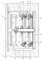
- FIG. 3 is a front cross-sectional view showing the internal structure of a film forming chamber.
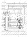
- FIG. 3 is an enlarged front cross-sectional view showing the internal structure of a film forming chamber.
- FIG. 3 is a front cross-sectional view showing the periphery of a work holding unit.
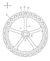
- the top view which showed the structure of the rotating wheel.
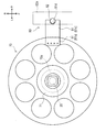
- the top view which showed the structure of a fixed disc and the control part.
- A A schematic diagram showing how a film forming process is performed in a state where a work is not tilted.
- (B) A schematic view showing how the film forming process is performed in a state where the work is inclined. The figure which showed an example of the evaluation regarding the lifetime of the tool of this application. The figure which showed an example of the evaluation regarding the generation
- the sputtering apparatus 1 is a vacuum processing apparatus (vacuum film forming apparatus) that performs film forming processing in vacuum.
- the sputtering apparatus 1 assumes a working tool as the work (processed article) W to be film-formed.
- the sputtering apparatus 1 mainly includes a film forming chamber 2, a work holding unit rotating unit 3, a motor 4, an exhaust device 5, a target (sputtering target) 6, and a heater 7.
- the film forming chamber 2 forms a space for performing a film forming process on the work W.
- the film forming chamber 2 is formed in a substantially columnar shape with its axis oriented in the vertical direction (see FIG. 2).
- the film forming chamber 2 is formed in a hollow shape.
- the work holding unit rotating unit 3 rotates a work holding unit 60 described later.
- the work holder rotating unit 3 is arranged in the film forming chamber 2.
- the motor 4 (see FIG. 1) is a drive source for rotationally driving the work holding unit rotation unit 3.
- the motor 4 is arranged outside the film forming chamber 2.
- the power of the motor 4 is transmitted to the work holding unit rotation unit 3 via an appropriate power transmission mechanism (for example, a shaft).
- the exhaust device 5 (see FIG. 1) exhausts the air in the film forming chamber 2 to adjust the inside of the film forming chamber 2 to a vacuum degree suitable for the film forming process.
- the target 6 is a material (film forming material) for forming a film on the work W.
- the target 6 is formed in a flat plate shape.
- the target 6 is arranged in the film forming chamber 2.
- a pair of targets 6 are provided with the workpiece holding unit rotating unit 3 interposed therebetween.
- the target 6 is arranged such that the plate surface is along the vertical direction.
- the target 6 is arranged so that the plate surface faces the center of the film forming chamber 2 (that is, the work holding unit rotating unit 3).
- the heater 7 is for heating the work W to improve film formation quality (uniformity, etc.).
- the heater 7 is arranged in the film forming chamber 2.
- a pair of heaters 7 are provided with the work holder rotating unit 3 interposed therebetween.
- the target 6 and the heater 7 are arranged at equal intervals around the work holding unit rotation unit 3.
- the work holding unit rotation unit 3 shown in FIGS. 3 and 4 mainly includes a rotary shaft 20, an upper rotary body 30, a rotary wheel 40, a mounting member 50, a work holding unit 60, a fixed disk 70, a restricting unit 80, and a cover 90. To do.
- the rotary shaft 20 serves as the center of rotation of the rotary wheel 40 described later.
- the rotating shaft 20 is formed in a substantially columnar shape.
- the rotating shaft 20 is arranged with its axis oriented in the vertical direction (vertical direction).
- An outer cylindrical member 21 formed in a cylindrical shape is fitted to the rotating shaft 20 so as to cover the side surface of the rotating shaft 20 so as to be integrally rotatable.
- a key groove 21 a is formed on the upper end of the outer cylinder member 21.
- the upper rotary body 30 is rotatable integrally with the rotary shaft 20.
- the upper rotating body 30 is formed in a circular shape in plan view.
- the upper end of the rotary shaft 20 is fixed to the center of the bottom surface of the upper rotary body 30.
- a key member 31 is fixed near the center of the bottom surface of the upper rotating body 30.
- the power of the motor 4 (see FIG. 1) can be transmitted to the upper rotating body 30.
- the upper rotary body 30 can rotate together with the rotary shaft 20 by the power from the motor 4.
- the rotary wheel 40 shown in FIGS. 3 to 6 rotates (revolves) a work holding unit 60 described later about the rotary shaft 20.
- the rotary wheel 40 mainly includes a boss portion 41, a rib 42, and an outer peripheral portion 43.
- the boss portion 41 is a portion formed at the center of the rotating wheel 40.
- the boss portion 41 is formed in a substantially cylindrical shape with its axis oriented in the vertical direction (vertical direction). At the center of the boss portion 41, a through hole 41a that vertically penetrates the boss portion 41 is formed.
- the rib 42 is a rod-shaped portion formed so as to extend from the boss portion 41 toward the outside of the boss portion 41 in the radial direction of the rotating wheel 40.
- a plurality of ribs 42 (five in the present embodiment) are formed around the boss portion 41 at equal intervals (see FIG. 6 ).
- the outer peripheral portion 43 is a portion that supports a work holding portion 60 described later.
- the outer peripheral portion 43 is formed in an annular shape centered on the boss portion 41 in a plan view.
- the inner peripheral surface of the outer peripheral portion 43 is fixed to the outer end portion of the rib 42 in the radial direction of the rotating wheel 40. In this way, the outer peripheral portion 43 is connected to the boss portion 41 via the rib 42.
- the boss portion 41, the rib 42, and the outer peripheral portion 43 are integrally formed.
- An inclined surface 43a and a through hole 43b are mainly formed in the outer peripheral portion 43.
- the inclined surface 43a shown in FIGS. 5 and 6 is formed on the upper surface of the outer peripheral portion 43.
- the inclined surface 43a is formed so as to face a direction inclined with respect to the vertical direction (axial direction of the rotating shaft 20).
- the inclined surface 43a is formed so as to incline downward toward the outer side in the radial direction of the rotary wheel 40.
- the through hole 43b is formed so as to vertically penetrate the outer peripheral portion 43.
- the upper end of the through hole 43b is formed so as to open to the inclined surface 43a.
- the through hole 43b is formed so as to extend perpendicularly to the inclined surface 43a. That is, the through hole 43b is formed so as to extend in a direction inclined with respect to the vertical direction (vertical direction). More specifically, the through hole 43b is formed so as to extend radially outward of the rotary wheel 40 as it extends upward.
- the lower end (lower opening) of the through hole 43b is closed by a plate-like closing member 43c.
- a plurality of inclined surfaces 43a and through holes 43b are formed at equal intervals along the circumferential direction of the outer peripheral portion 43.
- the rotating wheel 40 is provided on the rotating shaft 20 (outer cylinder member 21). Specifically, the boss portion 41 (through hole 41 a) of the rotary wheel 40 is inserted into the rotary shaft 20. At this time, the rotary wheel 40 and the rotary shaft 20 are engaged so as to be integrally rotatable. Further, a plurality of rotating wheels 40 are provided on the rotating shaft 20 so as to be vertically arranged at equal intervals. In FIGS. 1, 3 and 4, two rotating wheels 40 are shown as an example.
- the mounting member 50 shown in FIGS. 4 and 5 is for mounting a work holding portion 60, which will be described later, on the rotary wheel 40.
- the mounting member 50 mainly includes a main body portion 51 and a flange portion 52.
- the main body 51 is a portion formed in a cylindrical shape.
- the outer diameter of the main body portion 51 is formed to be substantially the same as the inner diameter of the through hole 43b of the rotary wheel 40.
- the flange portion 52 is a disk-shaped portion formed so as to expand in diameter from the vicinity of the upper end portion of the main body portion 51.
- the body 51 is inserted into the through hole 43b of the rotary wheel 40 from above.
- the flange portion 52 is fixed to the inclined surface 43a of the rotating wheel 40 by an appropriate fastening member (bolt or the like).
- the mounting member 50 is provided in each through hole 43b of the rotary wheel 40.
- the axis of the mounting member 50 (main body 51) is arranged so as to be inclined at the same angle as the through hole 43b.
- the work holding unit 60 holds the work W rotatably (rotatably).
- the work holding part 60 mainly includes a rotation support part 61 and a rotation driven part 62.
- the rotation support portion 61 holds the work W.
- the rotation support portion 61 mainly includes a holding portion 61a and a support portion 61b.
- the holding portion 61a is a portion that holds the work W.
- the holding portion 61a is formed in a substantially cylindrical shape (bottomed cylindrical shape) having a bottom surface (lower surface).
- the upper portion of the holding portion 61a is opened, and the work W inserted through this opening can be held.
- the holder 61a can not only directly hold the work W, but can also hold the work W via an appropriate member (a cap or the like that holds the work W).
- the support portion 61b is a portion supported by the rotating wheel 40 via the mounting member 50.
- the support portion 61b is formed in a substantially columnar shape.
- the outer diameter of the support portion 61b is formed to be smaller than the inner diameter of the mounting member 50.
- the support portion 61b is formed so as to protrude downward from the bottom surface of the holding portion 61a.
- the support portion 61b and the holding portion 61a are formed on the same axis.
- the support portion 61b is inserted into the main body portion 51 of the mounting member 50 from above.
- the support portion 61b is rotatably supported by the mounting member 50 (main body portion 51) via an appropriate bearing member 61c.
- the holding portion 61a is arranged so as to project upward from the rotary wheel 40.
- the axis of the rotation support portion 61 is arranged so as to be inclined at the same angle as the axis of the mounting member 50 (main body portion 51).
- the rotation support portion 61 is arranged so as to be inclined with respect to the plate surface of the target 6 arranged laterally, as shown in FIG.
- the rotation support portion 61 can rotate (rotate) about an axis inclined with respect to the axis (vertical direction) of the rotation shaft 20.
- any member can be used as the bearing member 61c.
- any member such as a ball bearing, a roller bearing, and a slide bearing can be appropriately selected. Further, it is possible to provide a plurality of bearing members 61c for one support portion 61b.
- the inclination angle of the axis of the support portion 61b (inclination angle ⁇ described later (see FIG. 5)) can be set arbitrarily.
- the support portion 61b can be set so as to be tilted by 20 to 80° with respect to the rotary shaft 20 and the target 6 (based on the vertical direction).
- the rotation driven part 62 is a part that comes into contact with a fixed disk 70 described later.
- the driven portion 62 is formed in a substantially circular flat plate shape when viewed in the axial direction of the rotation support portion 61.
- a through hole 62 a is formed at the center of the driven portion 62.
- the through hole 62 a of the rotation driven portion 62 is fitted to the holding portion 61 a of the rotation support portion 61 above the rotation wheel 40. As a result, the rotation driven portion 62 can rotate integrally with the rotation support portion 61.
- the work holding portion 60 is provided on the outer peripheral portion 43 of the rotary wheel 40 via the mounting member 50. Further, the plurality of work holding portions 60 are provided so as to be arranged along the outer peripheral portion 43 (that is, on the circumference around the rotation shaft 20).
- the fixed disk 70 shown in FIGS. 3 to 5 and 7 is for rotating the work holding unit 60.
- the fixed disk 70 is formed in a plate shape (disk shape) having a circular shape in plan view.
- a through hole 70a is formed at the center of the fixed disk 70.
- the fixed disk 70 is provided on the rotary shaft 20 via a fixed member 71 and a bearing member 72. Specifically, the outer ring of the bearing member 72 is fixed to the inside of the fixed disk 70 (through hole 70a) via the fixing member 71. The inner ring of the bearing member 72 is inserted into the rotary shaft 20 and fixed to the rotary shaft 20. As described above, the fixed disk 70 is provided so as to be rotatable relative to the rotary shaft 20 via the bearing member 72. The fixed disk 70 is provided above the rotating wheel 40 with an appropriate gap from the rotating wheel 40. That is, the fixed disks 70 are provided in the same number as the rotating wheels 40 so as to correspond to the rotating wheels 40. The outer peripheral end portion of the fixed disk 70 is arranged so as to come into contact with the rotation driven portion 62 of the work holding portion 60 provided on the corresponding rotary wheel 40.
- bearing member 72 any member can be used as the bearing member 72.
- any member such as a ball bearing, a roller bearing, and a slide bearing can be appropriately selected.
- the fixed disk 70 and the driven part 62 rotate so that the work holding part 60 rotates (revolves) about the rotation shaft 20 so that the power for rotating the work holding part 60 is transmitted to the work holding part 60.
- the fixed disk 70 and the rotationally driven portion 62 can be formed by a gear (for example, a bevel gear) having teeth that mesh with each other. Accordingly, the fixed disk 70 can continuously rotate (rotate) the work holding portion 60 (in particular, the work W can be continuously rotated in a state where the work W faces the target 6 ).
- the fixed disk 70 and the rotationally driven portion 62 may be configured to be in contact with each other and capable of transmitting power.
- gears for example, gears, a combination of a chain and a sprocket, a structure for transmitting power by using a meshing structure such as a combination of holes and protrusions, and a structure for transmitting power by using frictional force between contact surfaces may be used. .. Further, the fixed disk 70 and the driven part 62 may be in contact with each other via an inclusion that does not include a mechanical mechanism. In this case, the fixed disk 70, which is a rotating part, and the driven part 62, which is a part of the work holding part 60, come into contact with each other without interposing a mechanical mechanism.
- the fixed disk 70 and the rotation driven portion 62 are not limited to those that continuously transmit power and rotate the work holding portion 60 continuously like a gear.
- the fixed disk 70 and the rotationally driven portion 62 can intermittently rotate (spin) the work holding portion 60 by intermittently transmitting power using a cam or the like.
- the regulation unit 80 regulates the rotation of the fixed disc 70.
- the restriction portion 80 mainly includes a first restriction member 81 and a second restriction member 82.
- the first regulation member 81 is fixed to each fixed disc 70.
- the first regulating member 81 is formed by bending a rectangular plate material.
- the first regulating member 81 includes a horizontally extending left portion 81a, a midway portion 81b extending vertically upward from the right end of the left portion 81a, and a right portion 81c extending rightward from the upper end of the midway portion 81b, It is equipped with.
- the first restricting member 81 is formed such that the radially outer portion (right portion 81c) of the fixed disk 70 is higher than the radially inner portion (left portion 81a). This makes it possible to avoid interference with the work holding unit 60 and the work W.
- the left portion 81a of the first regulating member 81 is fixed near the right end portion of the upper surface of the fixed disc 70 by an appropriate fastening member (bolt or the like).
- the right portion 81c of the first regulating member 81 is arranged so as to project rightward from the fixed disc 70.
- a cutout portion 81d is formed in the right portion 81c.
- the second restricting member 82 engages with the first restricting member 81.
- the second regulation member 82 is formed in a substantially columnar shape.
- the second restricting member 82 is arranged with its axis in the vertical direction (vertical direction).
- the upper end of the second regulation member 82 is fixed to the upper surface of the film forming chamber 2 via the bracket 82a.
- the second regulation member 82 is engaged with the cutout portion 81d of the first regulation member 81 provided on each fixed disk 70. More specifically, the second regulating member 82 is fitted into the cutout portion 81d of the first regulating member 81, and the rotation of the fixed disc 70 is regulated.
- the rotation of the fixed disk 70 is restricted by engaging the first restriction member 81 provided on the fixed disk 70 with the second restriction member 82 fixed to the film forming chamber 2. As a result, even if the rotary shaft 20 rotates, the fixed disk 70 does not rotate.
- the cover 90 shown in FIGS. 3 to 5 covers the work holding unit 60.
- the cover 90 is formed by appropriately bending a plate-shaped member.
- the cover 90 is arranged so as to cover the work holding portion 60 from the side (outside in the radial direction of the fixed disc 70) and from above.
- a through hole 91 is formed in the cover 90.
- the work W held by the work holding portion 60 can be exposed to the outside of the cover 90 via the through hole 91.
- the cover 90 is fixed to the rotating wheel 40 by an appropriate method.
- the power of the motor 4 causes the rotating shaft 20 to rotate.
- the rotary wheel 40 rotates integrally with the rotary shaft 20.
- the work holding portion 60 provided on the outer peripheral portion 43 of the rotating wheel 40 rotates (revolves) about the rotating shaft 20.
- the rotation of the fixed disk 70 provided so as to be rotatable relative to the rotary shaft 20 is restricted by the restriction unit 80. Therefore, the fixed disk 70 does not rotate with the rotation of the rotary shaft 20.
- the rotation driven part 62 of the work holding part 60 rotates (revolves) about the rotating shaft 20 while contacting with the fixed (non-rotating) fixed disk 70.
- the work holding unit 60 rotates (revolves) about the rotation shaft 20 and rotates (rotates) about the axis of the work holding unit 60 (see FIG. 2 ).
- the work holding unit 60 rotates (revolves) about the rotation shaft 20
- the work holding unit 60 is viewed from the outside of the work holding unit 60 toward the rotation shaft 20 (in other words, as shown in FIGS. 4 and 5 ).
- the tilt angle ⁇ is always constant in a sectional view passing through the rotary shaft 20 and parallel to the rotary shaft 20.
- the inclination angle ⁇ is an angle with respect to the axis of the rotary shaft 20 and the plate surface of the target 6 in the cross section shown in FIGS. 4 and 5 (the cross section viewed from the circumferential direction of the virtual circle around the rotary shaft 20). means.
- the inclination angle ⁇ is the vertical direction (vertical direction) in the cross sections shown in FIGS. 4 and 5. It is an angle with respect to the imaginary line X along the line.
- the cross section viewed from the circumferential direction of the virtual circle centering on the rotation axis 20 can also be expressed as a cross section viewed from the circumference of the virtual circle centering on the rotation axis 20.
- the work holding unit 60 rotates (revolves) about the rotation shaft 20
- particles of the film-forming material collide with the work W from the target 6 at a position where the work W faces the target 6 to form a relatively thick film.
- the inclination angle ⁇ of the work holding part 60 (work W) with respect to the target 6 becomes substantially constant. Further, at this time, the film quality of the film formed on the entire exposed surface of the work W can be made uniform by rotating itself around the axis of the work holding unit 60.
- the method for manufacturing a film-formed product mainly includes a work holding step S1, an exhaust step S2, a work heating step S3, and a film forming step S4.
- the work holding step S1 is a step of causing the work holding unit 60 to hold the work W.
- the worker inserts the work W into the holding portion 61a of the work holding portion 60 and holds the work W by the work holding portion 60.
- the exhaust step S2 is a step of exhausting the air in the film forming chamber 2.
- the exhaust step S2 when the exhaust device 5 is operated, the air in the film forming chamber 2 is exhausted.
- the inside of the film forming chamber 2 is adjusted to a vacuum degree suitable for the film forming process.
- the work heating step S3 is a step of heating the work W.
- the work holding unit rotating unit 3 is operated and the rotation (revolution and rotation) of the work holding unit 60 is started. Further, in the work heating step S3, the heater 7 is operated to heat the work W held by the work holding unit 60 to an appropriate temperature.
- the film forming step S4 is a step of performing a film forming process on the work W.
- the work holder rotating unit 3 is continuously operated.
- a sputtering gas for example, an inert gas such as Ar
- RF Radio Frequency
- the particles of the film forming material knocked out from the target 6 adhere to the surface of the work W. By depositing these particles on the surface of the work W, a thin film can be formed. In this way, the work W (film-formed product) that has been subjected to the film-forming treatment can be manufactured.
- the work holding step S1, the exhaust step S2, the work heating step S3, and the film forming step S4 have been described in order for convenience, but the method for manufacturing the film formed article is not necessarily limited to this.
- the order of some steps can be changed (for example, the order of the exhaust step S2 and the work heating step S3 can be changed) or can be performed simultaneously (for example, the exhaust step S2 and the work heating step S3 can be performed at the same time). is there.
- the upper surface of the work W does not face the target 6, so that the particles of the film-forming material from the target 6 are unlikely to adhere to the upper surface of the work W. That is, there is a possibility that unevenness may occur in the formed thin film on the side surface and the upper surface of the work W.
- the work W is configured to rotate about an axis inclined with respect to the target 6.
- the side surface of the work W not only the side surface of the work W but also the upper surface can be made to face the target 6. Therefore, it is possible to prevent unevenness in the formed thin film on the side surface and the upper surface of the work W. Further, it is possible to suppress a difference in compressive stress of the thin film between the side surface and the upper surface of the work W, and improve the adhesion and homogeneity of the thin film.
- FIG. 10 shows a tool formed by the sputtering apparatus 1 according to the present embodiment (hereinafter, referred to as “tool of the present application”) and a tool formed by a conventionally known method as a comparative example (hereinafter, referred to as “comparative example”). “)” is shown as an example.
- sputtering conditions in the present embodiment an RF sputtering method using an RF power source is used, an AlCr-based alloy is used as a sputtering target, and a sputtering gas is a reactivity with a mixed gas in which a nitrogen gas is contained in an argon gas. A film was formed by sputtering.
- the tool targeted for evaluation is the "R0.5 carbide ball end mill”.
- the base material is a "hard metal (hard metal)" of WC-Co alloy, and an AlCrN-based film (coating) is applied.
- the material type (working material type) to be cut is SUS420J2 (HRC55).
- the processing conditions are: rotation speed: 30,000 (min ⁇ 1 ), feed rate: 1,500 (mm/min), and cut Rd(XY): 0.05 (mm).
- the life standard is (A): wear amount is 0.005 (mm)
- the life of the comparative example is 104.8 (m)
- the life of the tool of the present application is 200. It is 1 (m). That is, it can be seen that, when the life standard is (A): wear amount is 0.005 (mm), the tool life of the tool of the present application is approximately doubled as compared with the comparative example.
- the life standard is (B): the wear amount is 0.01 (mm)
- the life of the comparative example is 109.8 (m)
- the life of the tool of the present application is 293.5 (m). is there. That is, it can be seen that when the life criterion is (B): wear amount 0.01 (mm), the tool life of the tool of the present application is extended to about three times that of the comparative example.
- FIG. 11 shows an example of evaluation regarding occurrence of a chip between the tool of the present application and a comparative example.
- the number of occurrences of tool chipping was compared when 200 (m) cutting was performed under the same conditions as the example shown in FIG.
- the number of evaluations (the number of times of cutting) was 10, and after cutting, the tool was observed using a factory microscope at a magnification of 20 times.
- the chip was counted as having occurred.
- the tool formed by the sputtering apparatus 1 (method for producing a film-formed product) according to the present embodiment has a long life and suppresses the occurrence of chipping due to improvement in adhesion and homogeneity of the thin film (coating). It has been found that it is possible to achieve.
- the apparatus that performs sputtering is illustrated as an example of the vacuum processing apparatus (vacuum film forming apparatus), but the present invention is not limited to this and may be applied to various other vacuum processing. Is possible. For example, it can be applied to a physical vapor deposition method (physical vapor deposition method: PVD) other than the sputtering method using the physical movement of particles.
- PVD physical vapor deposition method
- PVD vacuum evaporation
- molecular beam evaporation molecular beam evaporation
- ion plating molecular beam evaporation
- ion beam evaporation PLD (plasma laser deposition), etc.
- sputtering system as exemplified in this embodiment, conventional sputtering, magnetron sputtering, ion beam sputtering, ECR sputtering, reactive sputtering (reactive gas (O 2 , N 2, etc.) is introduced, and oxidation is performed. Thing and the film formation of nitride).
- RF sputtering using an RF (high frequency) power source depending on the material of the work W.
- the thin film formed on the work W according to the present embodiment is composed of a single layer or a plurality of laminated layers including at least one of AlCrN, AlN, TiCrN, TiN, TiAlN, TiAlCrN, and Al 2 O 3 in particular.
- AlCrN AlN
- TiCrN TiCrN
- TiN TiAlN
- TiAlCrN TiAlCrN
- Al 2 O 3 Al 2 O 3
- additives As appropriate, Nb, Ta, Mo, V, Y, Si or the like can be added as an additive.
- the method for manufacturing a film-formed product is Holds the work W so that it can revolve around the first rotation shaft (rotation shaft 20) and can rotate around the second rotation shaft (work holding unit 60) inclined with respect to the target 6 (sputtering target).
- Work holding step S1 A film forming step S4 of forming a film on the work W by using the target 6 while performing revolution about the first rotation axis and rotation about the second rotation axis; Is included.
- the work W is held such that the inclination angle ⁇ with respect to the target 6 in a state of facing the target 6 is constant.
- the plurality of work holding portions 60 are subjected to the film forming processing in a state of being inclined at a constant angle with respect to the target 6 arranged on the outer side in the radial direction of the rotating wheel 40. Become. As a result, it is possible to suppress the dependency of the angle of the processing surface of the work W (a defect such as unevenness due to the change of the inclination angle ⁇ ).
- a film is formed on the work W by using high frequency sputtering.
- the film forming step S4 is to form a film on the work by using reactive sputtering.
- a substance for example, an oxide or a nitride generated by the reactive gas and the constituent material of the target 6 can be formed as a thin film.
- the work holding step S1 uses a machining tool as the work W.
- a film composed of a single layer or a plurality of layers is formed on the work W, the film including at least one of AlCrN, AlN, TiCrN, TiN, TiAlN, TiAlCrN, and Al 2 O 3. To do.
- the work W is continuously rotated about the second rotation axis in a state where the work W faces the target 6 by the revolution about the first rotation axis. It is something that rotates.
- the sputtering device 1 is The rotating shaft 20, A target 6 (sputtering target) arranged laterally of the rotary shaft 20; A rotating wheel 40 (rotating portion) rotatable about the rotating shaft 20; Workpieces W can be held, and they are arranged on the circumference around the rotation shaft 20 so as to be aligned, and provided on the rotation wheel 40 so as to be rotatable about an axis inclined with respect to the target 6.
- 70 rotary drive unit
- the target W is subjected to the film forming process by using the target 6 to suppress the occurrence of the unevenness of the thin film formed on the work W.
- the method for manufacturing a film-formed product according to the present embodiment is to manufacture a film-formed product using the sputtering apparatus 1.
- the work holding unit rotation unit 3 is The rotating shaft 20, A rotating wheel 40 (rotating portion) rotatable about the rotating shaft 20;
- the work W can be held, arranged so as to be lined up on a circumference centered on the rotation shaft 20, and rotated so as to be rotatable about an axis inclined with respect to the axis of the rotation shaft 20.
- a plurality of work holding portions 60 provided on the wheel 40, A fixed disk that is formed in a disk shape around the rotation shaft 20 and that is arranged so as to contact the plurality of work holding portions 60 and that rotates the work holding portions 60 as the rotation wheel 40 rotates.
- 70 (rotary drive unit), It is equipped with.
- the work holding unit 60 can be rotated (rotated) about an axis inclined with respect to the rotation axis 20, so that not only the side surface of the work W but also the film formation process Can be easily applied. This makes it possible to suppress the occurrence of unevenness in the thin film formed, and consequently to improve the adhesion and homogeneity of the thin film (coating).
- the plurality of work holding portions 60 are rotated (rotated) by the disk-shaped fixed disk 70 that is in contact with the plurality of work holding portions 60.
- the plurality of work holding portions 60 rotate and revolve while maintaining a posture inclined toward the outer side in the radial direction of the rotary wheel 40 at a constant angle. That is, the plurality of work holding portions 60 are subjected to the film forming process in a state of being inclined at a constant angle with respect to the target 6 arranged on the outer side in the radial direction of the rotating wheel 40.
- the rotary shaft 20 is formed so as to be rotatable by using power from the motor 4 (power source),
- the rotating wheel 40 is provided on the rotating shaft 20 so as to be rotatable integrally with the rotating shaft 20
- the fixed disk 70 is provided so as to be rotatable relative to the rotary shaft 20, It further comprises a restricting portion 80 for restricting the rotation of the fixed disk 70.
- the rotary wheel 40, the work holding part 60 provided on the rotary wheel 40, and the fixed disk 70 for rotating the work holding part 60 are provided in plural along the axial direction of the rotary shaft 20. is there.
- the work holding section 60 is A rotation support portion 61 that holds the work W and is rotatably supported by the rotation wheel 40, A rotation driven portion 62 fixed to the rotation support portion 61 and arranged so as to come into contact with the fixed disk 70; It is equipped with.
- the rotation support portion 61 is rotatably supported by the rotation wheel 40 via a bearing member 61c.
- the work holding unit 60 can be smoothly rotated. As a result, the driving force required to rotate the work holding unit 60 can be reduced.
- the rotation support portion 61 is arranged such that a lower portion thereof is inserted into the rotation wheel 40 and an upper portion thereof projects upward from the rotation wheel 40.
- the rotation driven portion 62 is provided on the rotation support portion 61 above the rotation wheel 40.
- the mechanism (rotationally driven portion 62) for rotating (spinning) the work holding portion 60 can be arranged at a relatively high position (above the rotating wheel 40), and this mechanism The maintainability can be improved.
- the sputtering apparatus 1 (vacuum processing apparatus) according to this embodiment includes the work holding unit rotating unit 3.
- the rotary wheel 40 according to the present embodiment is an embodiment of the rotary unit.
- the fixed disk 70 according to the present embodiment is an embodiment of the rotation drive unit.
- the target 6 according to this embodiment is an embodiment of a sputtering target.
- the motor 4 according to the present embodiment is an embodiment of a power source.
- the rotary shaft 20 and the work holding unit 60 according to the present embodiment are an embodiment of the first rotary shaft and the second rotary shaft.
- the sputtering apparatus 1 according to the present embodiment is an embodiment of a vacuum processing apparatus.
- a tool for machining (a tool for machining such as cutting, grinding, and polishing) is illustrated as an example of the work W, but the present invention is not limited to this. That is, the work W that is the target of film formation can be arbitrarily selected.
- various articles such as punch parts (blades for punching), die parts for die casting, blades of cutters, and the like are assumed.
- the shape of the work W is not limited, and any shape can be used.
- a member having a complicated three-dimensional shape may be used as well as a rod-shaped, columnar, or prismatic member extending in one direction. It is also possible to use a member having a complicated surface shape (for example, the cutting edge of a tool) as the work W.
- the work W is held in a state of being inclined with respect to the rotary shaft 20 and the target 6, but the angle and direction of this inclination can be arbitrarily changed.
- the inclination angle ⁇ of the work holding portion 60 (and thus the inclination angle ⁇ of the work W) can be changed. ..
- the inclination angle ⁇ of the work W can be changed by replacing not only the rotating wheel 40 but also other members (for example, the mounting member 50).
- the rotary wheel 40, the work holding part 60 provided on the rotary wheel 40, and the fixed disks 70 corresponding to the work holding part 60 are arranged vertically (two in a row).
- the number of the rotating wheels 40 and the like is not limited. That is, it is possible to provide only one rotary wheel 40 or the like in the sputtering apparatus 1 or three or more rotary wheels 40 or the like.
- the rotating wheel 40 and the like are arranged so as not to overlap with other rotating wheels 40 and the like that are vertically adjacent when viewed from the side.
- the rotary wheel 40, the work holding unit 60, and the fixed disk 70 provided below are located below the rotary wheel 40 and the like provided above (upper stage). It is arranged to be located.
- the present invention is not limited to this.
- it is possible to further provide an ion gun and perform pretreatment for example, the oxide on the surface of the work W is bombarded with argon ions to be removed.
- pretreatment for example, the oxide on the surface of the work W is bombarded with argon ions to be removed.
- the motor 4 is illustrated as an example of the power source, but the present invention is not limited to this. That is, it is possible to use other power sources (engine, actuator, etc.).
- the speed (rotation speed) of rotation (revolution and rotation) of the work holding unit 60 can be set appropriately. For example, while the work holding unit 60 passes the front surface of the target 6 by rotation (revolution) about the rotation axis 20 (while facing the target 6), the work holding unit 60 makes at least one rotation (360). °) It is set to rotate more than that. As a result, the film forming material from the target 6 can be attached to the entire area of the work W, and the adhesion and homogeneity of the thin film can be further improved.
Landscapes
- Chemical & Material Sciences (AREA)
- Engineering & Computer Science (AREA)
- Mechanical Engineering (AREA)
- Chemical Kinetics & Catalysis (AREA)
- Materials Engineering (AREA)
- Metallurgy (AREA)
- Organic Chemistry (AREA)
- Physical Vapour Deposition (AREA)
- Cutting Tools, Boring Holders, And Turrets (AREA)
Abstract
ワークに形成される薄膜のムラの発生を抑制することができる成膜品の製造方法を提供する。第一回転軸(回転軸20)を中心として公転可能、かつターゲット6(スパッタリングターゲット)に対して傾斜した第二回転軸(ワーク保持部60)を中心として自転可能となるようにワークWを保持するワーク保持工程と、前記第一回転軸を中心とする公転、及び前記第二回転軸を中心とする自転を行いながら、前記ターゲット6を用いて、前記ワークWに対して成膜を行う成膜工程と、を含む。
Description
本発明は、成膜品の製造方法及びスパッタリング装置の技術に関する。
従来の成膜品の製造方法及びスパッタリング装置の技術は、例えば、特許文献1に記載の如くである。
特許文献1には、小径工具を回転させながらコーティングを行うコーティング装置が開示されている。このコーティング装置は、小径工具を保持すると共に回転(自転)可能な自転ジグ、自転ジグを小公転軸を中心として回転(小公転)させる小公転ジグ、及び小公転ジグを大公転軸を中心として回転(大公転)させる大公転ジグを具備している。自転ジグ、小公転ジグ及び大公転ジグの軸線(回転中心線)は、互いに平行になるように配置されている。また、この大公転ジグ等の側方には、ターゲットが配置されている。
このように構成されたコーティング装置においては、小径工具を自転、小公転及び大公転させながら、ターゲットから発せられた材料で小径工具にコーティングが施される。このような自転及び公転を行うことで、小径工具の表面全体にコーティングを施すことができる。
しかしながら、特許文献1に記載の技術では、小径工具を回転(自転及び公転(小公転及び大公転))させた場合、小径工具の側面はターゲットと対向するものの、上面はターゲットと対向することはない。このため、小径工具の側面と上面ではコーティングにムラが生じるおそれがある点で、改善の余地があった。
本発明は以上の如き状況に鑑みてなされたものであり、その解決しようとする課題は、ワークに形成される薄膜のムラの発生を抑制することができる成膜品の製造方法及びスパッタリング装置を提供することである。
本発明の解決しようとする課題は以上の如くであり、この課題を解決するため、本発明に係る成膜品の製造方法は、第一回転軸を中心として公転可能、かつスパッタリングターゲットに対して傾斜した第二回転軸を中心として自転可能となるようにワークを保持するワーク保持工程と、前記第一回転軸を中心とする公転、及び前記第二回転軸を中心とする自転を行いながら、前記スパッタリングターゲットを用いて、前記ワークに対して成膜を行う成膜工程と、を具備するものである。
また、本発明に係るスパッタリング装置は、回転軸と、前記回転軸の側方に配置されたスパッタリングターゲットと、前記回転軸を中心として回転可能な回転部と、ワークを保持可能であり、前記回転軸を中心とする円周上に並ぶように配置され、前記スパッタリングターゲットに対して傾斜した軸線を中心として回転可能となるように前記回転部に設けられた複数のワーク保持部と、前記回転軸を中心とする円盤状に形成されると共に、複数の前記ワーク保持部と接触するように配置され、前記回転部の回転に伴って前記ワーク保持部を回転させる回転駆動部と、を具備するものである。
また、本発明に係る成膜品の製造方法は、前記スパッタリング装置を用いて成膜品を製造するものである。
本発明によれば、ワークに形成される薄膜のムラの発生を抑制することができる。
以下では、図中の矢印U、矢印D、矢印L、矢印R、矢印F及び矢印Bで示した方向を、それぞれ上方向、下方向、左方向、右方向、前方向及び後方向と定義して説明を行う。
以下では、図1及び図2を用いて、本実施形態に係るスパッタリング装置1の概略について説明する。
スパッタリング装置1は、真空中で成膜処理を行う真空処理装置(真空成膜装置)である。本実施形態に係るスパッタリング装置1は、成膜対象となるワーク(処理品)Wとして、加工用の工具を想定している。スパッタリング装置1は、主として成膜室2、ワーク保持部回転ユニット3、モータ4、排気装置5、ターゲット(スパッタリングターゲット)6及びヒータ7を具備する。
成膜室2は、ワークWに成膜処理を施すための空間を形成するものである。成膜室2は、軸線を上下方向に向けた略円柱状に形成される(図2参照)。成膜室2は、中空状に形成される。
ワーク保持部回転ユニット3は、後述するワーク保持部60を回転させるものである。ワーク保持部回転ユニット3は、成膜室2内に配置される。
モータ4(図1参照)は、ワーク保持部回転ユニット3を回転駆動させるための駆動源である。モータ4は、成膜室2の外部に配置される。モータ4の動力は、適宜の動力伝達機構(例えば軸等)を介してワーク保持部回転ユニット3に伝達される。
排気装置5(図1参照)は、成膜室2内の空気を排出することで、成膜室2内を成膜処理に適した真空度となるように調節するものである。
ターゲット6は、ワークWに成膜される材料(成膜材料)である。ターゲット6は、平板状に形成される。ターゲット6は、成膜室2内に配置される。ターゲット6は、ワーク保持部回転ユニット3を挟んで一対設けられる。ターゲット6は、板面が垂直方向に沿うように配置される。またターゲット6は、板面が成膜室2の中央(すなわち、ワーク保持部回転ユニット3)を向くように配置される。
ヒータ7は、ワークWを加熱して、成膜品質(均一性等)を向上させるためのものである。ヒータ7は、成膜室2内に配置される。ヒータ7は、ワーク保持部回転ユニット3を挟んで一対設けられる。ターゲット6及びヒータ7は、ワーク保持部回転ユニット3の周囲に等間隔に配置される。
次に、ワーク保持部回転ユニット3についてより具体的に説明する。
図3及び図4に示すワーク保持部回転ユニット3は、主として回転軸20、上部回転体30、回転ホイール40、取付部材50、ワーク保持部60、固定円盤70、規制部80及びカバー90を具備する。
回転軸20は、後述する回転ホイール40の回転中心となるものである。回転軸20は、略円柱状に形成される。回転軸20は、軸線を鉛直方向(上下方向)に向けて配置される。回転軸20には、回転軸20の側面を覆うように、円筒状に形成された外筒部材21が一体的に回転可能となるように嵌め合わされる。外筒部材21の上端部には、キー溝21aが形成される。
上部回転体30は、回転軸20と一体的に回転可能なものである。上部回転体30は、平面視円形状に形成される。上部回転体30の底面の中心には、回転軸20の上端部が固定される。上部回転体30の底面の中心近傍には、キー部材31が固定される。このキー部材31が外筒部材21のキー溝21aに係合されることで、上部回転体30と回転軸20との相対回転が規制される。すなわち、上部回転体30は、回転軸20と一体的に回転することができる。上部回転体30の上部は、成膜室2の上面に回転可能に支持される。上部回転体30には、モータ4(図1参照)の動力が伝達可能とされる。上部回転体30は、モータ4からの動力によって、回転軸20と共に回転することができる。
図3から図6までに示す回転ホイール40は、後述するワーク保持部60を回転軸20を中心として回転(公転)させるものである。回転ホイール40は、主としてボス部41、リブ42及び外周部43を具備する。
ボス部41は、回転ホイール40の中心に形成される部分である。ボス部41は、軸線を鉛直方向(上下方向)に向けた略円筒状に形成される。ボス部41の中心には、ボス部41を上下に貫通する貫通孔41aが形成される。
リブ42は、ボス部41から、回転ホイール40の径方向においてボス部41の外側に向けて延びるように形成される棒状の部分である。リブ42は、ボス部41の周囲に等間隔に複数(本実施形態では5つ)形成される(図6参照)。
外周部43は、後述するワーク保持部60を支持する部分である。外周部43は、平面視において、ボス部41を中心とする円環状に形成される。外周部43の内周面は、回転ホイール40の径方向においてリブ42の外側の端部に固定される。このようにして、外周部43は、リブ42を介してボス部41と接続される。なお、本実施形態においては、ボス部41、リブ42及び外周部43は一体的に形成されている。外周部43には、主として傾斜面43a及び貫通孔43bが形成される。
図5及び図6に示す傾斜面43aは、外周部43の上面に形成される。傾斜面43aは、上下方向(回転軸20の軸線方向)に対して傾斜する方向を向くように形成される。具体的には、傾斜面43aは、回転ホイール40の径方向外側に向かうにつれて下方に傾斜するように形成される。
貫通孔43bは、外周部43を上下に貫通するように形成される。貫通孔43bの上端は、傾斜面43aに開口するように形成される。貫通孔43bは、傾斜面43aに対して垂直に延びるように形成される。すなわち、貫通孔43bは、鉛直方向(上下方向)に対して傾斜する方向に延びるように形成される。より具体的には、貫通孔43bは、上方に向かうにつれて回転ホイール40の径方向外側に延びるように形成される。貫通孔43bの下端(下側の開口部)は、板状の閉塞部材43cによって閉塞される。
図6に示すように、傾斜面43a及び貫通孔43bは、外周部43の周方向に沿って等間隔に複数形成される。
図4に示すように、回転ホイール40は、回転軸20(外筒部材21)に設けられる。具体的には、回転ホイール40のボス部41(貫通孔41a)が、回転軸20に挿通される。この際、回転ホイール40と回転軸20は一体的に回転可能となるように係合される。また回転軸20には、回転ホイール40が上下に等間隔に複数並ぶように設けられる。図1、図3及び図4では、一例として2つの回転ホイール40を図示している。
図4及び図5に示す取付部材50は、後述するワーク保持部60を回転ホイール40に取り付けるためのものである。取付部材50は、主として本体部51及びフランジ部52を具備する。
本体部51は、円筒状に形成された部分である。本体部51の外径は、回転ホイール40の貫通孔43bの内径と略同一となるように形成される。
フランジ部52は、本体部51の上端部近傍から拡径するように形成された円盤状の部分である。
本体部51は、回転ホイール40の貫通孔43bに上方から挿入される。フランジ部52は、回転ホイール40の傾斜面43aに適宜の締結部材(ボルト等)によって固定される。このようにして、取付部材50は、回転ホイール40の各貫通孔43bに設けられる。取付部材50(本体部51)の軸線は、貫通孔43bと同じ角度で傾斜するように配置される。
ワーク保持部60は、ワークWを回転(自転)可能に保持するものである。ワーク保持部60は、主として回転支持部61及び被回転駆動部62を具備する。
回転支持部61は、ワークWを保持するものである。回転支持部61は、主として保持部61a及び支持部61bを具備する。
保持部61aは、ワークWを保持する部分である。保持部61aは、底面(下面)を有する略円筒状(有底筒状)に形成される。保持部61aの上部は開口され、この開口から挿入されたワークWを保持することができる。なお、保持部61aは、ワークWを直接保持するだけでなく、適宜の部材(ワークWを保持するキャップ等)を介してワークWを保持することができる。
支持部61bは、取付部材50を介して回転ホイール40に支持される部分である。支持部61bは、略円柱状に形成される。支持部61bの外径は、取付部材50の内径よりも小さくなるように形成される。支持部61bは、保持部61aの底面から下方に向かって突出するように形成される。支持部61b及び保持部61aは、同一軸線上に形成される。
支持部61bは、取付部材50の本体部51に上方から挿入される。支持部61bは、適宜の軸受部材61cを介して、取付部材50(本体部51)に回転可能に支持される。支持部61bを本体部51に挿入することで、保持部61aが回転ホイール40から上方に向かって突出するように配置される。回転支持部61の軸線は、取付部材50(本体部51)の軸線と同じ角度で傾斜するように配置される。換言すると、回転支持部61は、図1に示すように、側方に配置されたターゲット6の板面に対して傾斜するように配置される。回転支持部61は、回転軸20の軸線(上下方向)に対して傾斜した軸線を中心として回転(自転)することができる。
なお、軸受部材61cとしては、任意の部材を用いることができる。例えば、ボールベアリング、ローラーベアリング、すべり軸受等、任意の部材を適宜選択することができる。また、1つの支持部61bに対して、軸受部材61cを複数設けることも可能である。
また、支持部61bの軸線の傾斜角度(後述する傾斜角度α(図5参照))は、任意に設定することができる。例えば、支持部61bが、回転軸20やターゲット6に対して(鉛直方向を基準として)、20~80°傾斜するように設定することができる。
被回転駆動部62は、後述する固定円盤70と接触する部分である。被回転駆動部62は、回転支持部61の軸線方向から見て略円形の平板状に形成される。被回転駆動部62の中心には貫通孔62aが形成される。被回転駆動部62の貫通孔62aは、回転ホイール40の上方において、回転支持部61の保持部61aに嵌め合わされる。これによって、被回転駆動部62は、回転支持部61と一体的に回転可能となる。
このようにしてワーク保持部60は、取付部材50を介して、回転ホイール40の外周部43に設けられる。またワーク保持部60は、外周部43に沿って(すなわち、回転軸20を中心とする円周上に)並ぶように複数設けられる。
図3から図5、及び図7に示す固定円盤70は、ワーク保持部60を回転させるためのものである。固定円盤70は、平面視円形の板状(円盤状)に形成される。固定円盤70の中心には、貫通孔70aが形成される。
図4に示すように、固定円盤70は、固定部材71及び軸受部材72を介して、回転軸20に設けられる。具体的には、固定円盤70の内側(貫通孔70a)には、固定部材71を介して軸受部材72の外輪が固定される。この軸受部材72の内輪が、回転軸20に挿通されて、回転軸20に固定される。このように、固定円盤70は軸受部材72を介して回転軸20に相対回転可能に設けられる。固定円盤70は、回転ホイール40の上方に、回転ホイール40と適宜の間隔を空けて設けられる。すなわち固定円盤70は、各回転ホイール40に対応するように、回転ホイール40と同数設けられる。固定円盤70の外周端部は、対応する回転ホイール40に設けられたワーク保持部60の被回転駆動部62と接触するように配置される。
なお、軸受部材72としては、任意の部材を用いることができる。例えば、ボールベアリング、ローラーベアリング、すべり軸受等、任意の部材を適宜選択することができる。
固定円盤70及び被回転駆動部62は、ワーク保持部60が回転軸20を中心として回転(公転)することで、ワーク保持部60を自転させるための動力がワーク保持部60に伝達されるように構成されている。例えば、固定円盤70及び被回転駆動部62は、互いに噛み合う歯を有する歯車(例えば、かさ歯車等)により形成することができる。これにより、固定円盤70はワーク保持部60を連続的に回転(自転)させる(特に、ワークWがターゲット6と対向している状態で、このワークWを連続的に回転させる)ことができる。その他、固定円盤70及び被回転駆動部62は、互いに接触して動力を伝達可能な構成であればよい。例えば、歯車、チェーンとスプロケットとの組み合わせ、穴部と突起部との組み合わせ等の噛み合わせ構造を用いて動力を伝達する構成、接触面同士の摩擦力を用いて動力を伝達する構成等でもよい。
また、固定円盤70と被回転駆動部62とは、機械的な機構を含まない介在物を介して接触してもよい。この場合、回転部である固定円盤70とワーク保持部60の一部である被回転駆動部62とは、機械的な機構を介在することなく、接触することになる。
また、固定円盤70と被回転駆動部62とは、機械的な機構を含まない介在物を介して接触してもよい。この場合、回転部である固定円盤70とワーク保持部60の一部である被回転駆動部62とは、機械的な機構を介在することなく、接触することになる。
また、固定円盤70及び被回転駆動部62は、歯車のように連続的に動力を伝達させ、ワーク保持部60を連続的に回転させるものに限らない。例えば固定円盤70及び被回転駆動部62は、カム等を用いて断続的に動力を伝達することで、ワーク保持部60を断続的に回転(自転)させることも可能である。
規制部80は、固定円盤70の回転を規制するものである。規制部80は、主として第一規制部材81及び第二規制部材82を具備する。
第一規制部材81は、各固定円盤70に固定されるものである。第一規制部材81は、矩形状の板材を屈曲させて形成される。具体的には、第一規制部材81は、水平に延びる左部81aと、左部81aの右端から鉛直上方に延びる中途部81bと、中途部81bの上端から右方に延びる右部81cと、を具備する。このように、第一規制部材81は、固定円盤70の径方向外側の部分(右部81c)が径方向内側の部分(左部81a)よりも高くなるように形成されている。これによって、ワーク保持部60やワークWとの干渉を避けることができる。
第一規制部材81の左部81aは、固定円盤70の上面の右端部近傍に適宜の締結部材(ボルト等)によって固定される。第一規制部材81の右部81cは、固定円盤70から右方に突出するように配置される。右部81cには、切欠部81dが形成される。
第二規制部材82は、第一規制部材81と係合するものである。第二規制部材82は、略円柱状に形成される。第二規制部材82は、軸線を鉛直方向(上下方向)に向けて配置される。第二規制部材82の上端部は、ブラケット82aを介して成膜室2の上面に固定される。第二規制部材82は、各固定円盤70に設けられた第一規制部材81の切欠部81dに係合される。より具体的には、第一規制部材81の切欠部81dに、第二規制部材82が嵌め込まれて、固定円盤70の回転が規制されることになる。
このように、固定円盤70に設けられた第一規制部材81が、成膜室2に固定された第二規制部材82と係合することで、固定円盤70の回転が規制される。これによって、回転軸20が回転しても、固定円盤70が回転することはない。
図3から図5までに示すカバー90は、ワーク保持部60を覆うものである。カバー90は、板状の部材を適宜屈曲させて形成される。カバー90は、ワーク保持部60を側方(固定円盤70の径方向外側)及び上方から覆うように配置される。カバー90には、貫通孔91が形成される。貫通孔91を介して、ワーク保持部60に保持されたワークWをカバー90の外側に露出させることができる。カバー90は、回転ホイール40に適宜の方法で固定される。
次に、モータ4の動力によってワーク保持部回転ユニット3が動作する様子について説明する。
モータ4が駆動すると、モータ4の動力によって回転軸20が回転する。回転ホイール40は、回転軸20と一体的に回転する。これによって、回転ホイール40の外周部43に設けられたワーク保持部60は、回転軸20を中心として回転(公転)する。
一方、回転軸20に対して相対回転可能に設けられた固定円盤70は、規制部80によって回転が規制されている。このため、固定円盤70は、回転軸20の回転に伴って回転することはない。
ワーク保持部60の被回転駆動部62は、固定された(回転しない)固定円盤70と接触しながら、回転軸20を中心として回転(公転)することになる。これによって、ワーク保持部60は、回転軸20を中心として回転(公転)しながら、このワーク保持部60の軸線を中心として回転(自転)する(図2参照)。
また、ワーク保持部60は、回転軸20を中心として回転(公転)する場合、ワーク保持部60の外側から回転軸20に向う方向に見た(換言すれば、図4及び図5に示すような、回転軸20を通り、かつ回転軸20と平行な断面視における)傾斜角度αが常に一定となる。なお、傾斜角度αとは、図4及び図5に示す断面(回転軸20を中心とする仮想円の周方向から見た断面)において、回転軸20の軸線やターゲット6の板面に対する角度を意味する。本実施形態では、回転軸20の軸線及びターゲット6の板面は上下方向(鉛直方向)に平行であるため、傾斜角度αは、図4及び図5に示す断面において上下方向(鉛直方向)に沿う仮想線Xに対する角度となる。回転軸20を中心とする仮想円の周方向から見た断面とは、回転軸20を中心とする仮想円の円周上から見た断面と表現することもできる。
従って、ワーク保持部60が回転軸20を中心として回転(公転)すると、ワークWがターゲット6に対向する位置で、ターゲット6から成膜材料の粒子がワークWに衝突して比較的厚く成膜される成膜領域において、ターゲット6に対するワーク保持部60(ワークW)の傾斜角度αがほぼ一定となる。さらに、この際にワーク保持部60の軸線を中心として自転することで、ワークWの露出面全体に形成される膜の膜質の均一化を図ることができる。
次に、上述の如く構成されたスパッタリング装置1を用いた成膜品の製造方法(スパッタリング方法)について説明する。
図8に示すように、本実施形態に係る成膜品の製造方法は、主としてワーク保持工程S1、排気工程S2、ワーク加熱工程S3及び成膜工程S4を含む。
ワーク保持工程S1は、ワーク保持部60にワークWを保持させる工程である。ワーク保持工程S1において、作業者は、ワークWをワーク保持部60の保持部61aに挿入し、このワーク保持部60によってワークWを保持させる。
排気工程S2は、成膜室2内の空気を排出する工程である。排気工程S2において、排気装置5が作動されると、成膜室2内の空気が排出される。排気装置5を適宜制御することで、成膜室2内が成膜処理に適した真空度となるように調節される。
ワーク加熱工程S3は、ワークWを加熱する工程である。ワーク加熱工程S3において、モータ4が駆動されると、ワーク保持部回転ユニット3が作動され、ワーク保持部60の回転(公転及び自転)が開始される。またワーク加熱工程S3において、ヒータ7が作動され、ワーク保持部60に保持されたワークWが適宜の温度まで加熱される。
成膜工程S4は、ワークWに成膜処理を施す工程である。成膜工程S4においては、引き続きワーク保持部回転ユニット3が作動される。また成膜工程S4において、成膜室2内にスパッタリングガス(例えば、Ar等の不活性ガス)が供給される。この状態でターゲット6にマイナスの電圧又は高周波(RF:Radio Frequency)の電圧を印加することで、グロー放電を発生させる。これによって、スパッタリングガスをイオン化し、このイオンをターゲット6の表面に高速で衝突させることで、ターゲット6を構成する成膜材料の粒子(スパッタ粒子)を叩き出す。ターゲット6から叩き出された成膜材料の粒子は、ワークWの表面に付着する。この粒子をワークWの表面に堆積させることで、薄膜を形成することができる。このようにして、成膜処理が施されたワークW(成膜品)を製造することができる。
なお、本実施形態では、便宜上、ワーク保持工程S1、排気工程S2、ワーク加熱工程S3及び成膜工程S4を順に説明したが、成膜品の製造方法は必ずしもこれに限るものではない。例えば、一部工程の順序を入れ替えたり(例えば、排気工程S2とワーク加熱工程S3の順序を入れ替える等)、同時に行うこと(例えば、排気工程S2とワーク加熱工程S3を同時に行う等)も可能である。
ここで、図9を用いて、スパッタリング装置1を用いた成膜品の製造方法により、ワークWに形成される薄膜のムラの発生が抑制される様子について説明する。なお、図9においては説明の便宜上、ワークWの形状を簡略化して、円柱状のものとして図示している。
比較例として、図9(a)に示すように、仮にワークWが傾斜しておらず、鉛直方向を向いた軸線を中心として自転する場合を想定する。この場合、ワークWは自転しているため、ワークWの側面全体が、ワークWの側方に配置されたターゲット6と対向することになる。これによって、ターゲット6からの成膜材料の粒子を、ワークWの側面全体に付着させることができる。
一方、ワークWが自転しても、ワークWの上面がターゲット6と対向することはないため、ターゲット6からの成膜材料の粒子は、ワークWの上面に付着し難い。すなわち、ワークWの側面と上面で、形成される薄膜にムラが生じてしまうおそれがある。
特にスパッタリング(スパッタ法)による成膜処理では、ワークWの側面と上面に形成された薄膜の圧縮応力(内部応力)に差が生じ、この圧縮応力の差によって薄膜の密着性や均質性の低下等が懸念される。
これに対して本実施形態では、図9(b)に示すように、ターゲット6に対して傾斜した軸線を中心としてワークWが自転するように構成されている。この場合、ワークWの側面だけでなく、上面も、ターゲット6と対向させることができる。このため、ワークWの側面と上面で、形成される薄膜にムラが生じるのを抑制することができる。また、ワークWの側面と上面で、薄膜の圧縮応力に差が生じるのを抑制することができ、薄膜の密着性や均質性の向上を図ることができる。
以下では、図10及び図11を用いて、本実施形態に係るスパッタリング装置1(成膜品の製造方法)により成膜された工具の評価の一例について説明する。
図10には、本実施形態に係るスパッタリング装置1により成膜された工具(以下、「本願工具」と称する)と、比較例として従来公知の方法で成膜された工具(以下、「比較例」と称する)との、寿命に関する評価の一例を示している。
ここで、本実施形態でのスパッタリング条件としては、RF電源を用いたRFスパッタリング法により、スパッタリングターゲットにAlCr系合金を用いて、スパッタリングガスがアルゴンガスに窒素ガスを含有させた混合ガスによる反応性スパッタリングで成膜を行った。
なお、評価の対象とした工具は「R0.5超硬ボールエンドミル」である。この工具は、母材がWC-Co合金の「超硬材(超硬合金)」であり、AlCrN系の成膜(コーティング)が施されたものである。
また評価試験として、上記2種類の工具を用いて切削加工を行った。切削加工の対象となる材種(被削材種)はSUS420J2(HRC55)である。加工条件は、回転数:30,000(min-1)、送り速度:1,500(mm/min)、切り込みRd(XY):0.05(mm)である。
また評価の際の寿命の基準(工具の寿命を判断するための工具の磨耗量)として、(A):磨耗量0.005(mm)、(B):磨耗量0.01(mm)の、2パターンの基準を設定した。図10の横軸は加工距離、縦軸は磨耗量を示している。
図10に示すように、寿命基準を(A):磨耗量0.005(mm)とした場合、比較例の寿命が104.8(m)であるのに対し、本願工具の寿命は200.1(m)である。すなわち、寿命基準を(A):磨耗量0.005(mm)とした場合、本願工具は比較例と比べて工具寿命が約2倍に延びていることが分かる。
また、寿命基準を(B):磨耗量0.01(mm)とした場合、比較例の寿命が109.8(m)であるのに対し、本願工具の寿命は293.5(m)である。すなわち、寿命基準を(B):磨耗量0.01(mm)とした場合、本願工具は比較例と比べて工具寿命が約3倍に延びていることが分かる。
図11には、本願工具と比較例との、欠けの発生に関する評価の一例を示している。
なお、欠けの発生に関する評価として、図10に示した例と同じ条件で200(m)の切削加工を行った場合における、工具の欠けの発生回数を比較した。評価回数(切削加工の回数)は10回であり、切削加工後に工場顕微鏡を用いて20倍の倍率で工具を観察した。欠けの大きさに関係なく、欠けが確認された場合、欠けが発生したものとしてカウントした。
その結果、図11に示すように、比較例では、10回の評価回数のうち、8回で欠けの発生が確認された。これに対して、本願工具では、10回の評価回数のうち、わずか2回だけ欠けの発生が確認された。すなわち、本願工具の欠けの発生率は、比較例の4分の1になっていることが分かる。
このように本実施形態に係るスパッタリング装置1(成膜品の製造方法)により成膜された工具は、薄膜(コーティング)の密着性や均質性の向上により、長寿命化や欠けの発生の抑制を図ることが可能となることが分かった。
なお、本実施形態では、真空処理装置(真空成膜装置)の一例としてスパッタリングを行う装置(スパッタリング装置1)を例示したが、本発明はこれに限らず、その他種々の真空処理に適用することが可能である。例えば、粒子の物理的な運動を利用したスパッタリング法以外の物理的気相成長法(物理蒸着法:PVD)に適用することが可能である。
なお、PVDの中には、蒸着源を加熱して蒸発させて成膜を行う蒸発系として、真空蒸着、分子線蒸着、イオンプレーティング、イオンビーム蒸着、PLD(プラズマーレーザーデポジション)などがある。また、本実施形態で例示したようなスパッタ系として、コンベンショナル・スパッタリング、マグネトロン・スパッタリング、イオンビーム・スパッタリング、ECRスパッタリング、反応性スパッタリング(反応性ガス(O2、N2等)を導入し、酸化物や窒化物の成膜を行うもの)などがある。また、ワークWの材料に応じて、RF(高周波)電源を用いたRFスパッタリングを用いることも可能である。
また、本実施形態によりワークWに形成される薄膜としては、特にAlCrN、AlN、TiCrN、TiN、TiAlN、TiAlCrN、Al2O3のうちの少なくとも1つを含む、単層又は複数積層からなるものを想定しているが、その他任意の薄膜を形成することも可能である。
また、上記成膜材料に加えて、適宜添加物を加えることも可能である。例えば、添加剤として、Nb、Ta、Mo、V、Y、Si等を加えることが可能である。
以上の如く、本実施形態に係る成膜品の製造方法は、
第一回転軸(回転軸20)を中心として公転可能、かつターゲット6(スパッタリングターゲット)に対して傾斜した第二回転軸(ワーク保持部60)を中心として自転可能となるようにワークWを保持するワーク保持工程S1と、
前記第一回転軸を中心とする公転、及び前記第二回転軸を中心とする自転を行いながら、前記ターゲット6を用いて、前記ワークWに対して成膜を行う成膜工程S4と、
を含むものである。
第一回転軸(回転軸20)を中心として公転可能、かつターゲット6(スパッタリングターゲット)に対して傾斜した第二回転軸(ワーク保持部60)を中心として自転可能となるようにワークWを保持するワーク保持工程S1と、
前記第一回転軸を中心とする公転、及び前記第二回転軸を中心とする自転を行いながら、前記ターゲット6を用いて、前記ワークWに対して成膜を行う成膜工程S4と、
を含むものである。
このように構成することにより、ワークWに形成される薄膜のムラの発生を抑制することができる。例えば本実施形態のように、ワーク保持部60を、ターゲット6に対して傾斜した軸線を中心として回転(自転)可能とすることで、ワークWの側面だけでなく、上面にも成膜処理を施しやすくすることができる。これによって形成される薄膜のムラの発生を抑制することができ、ひいては薄膜(コーティング)の密着性や均質性の向上を図ることができる。
また、前記ワーク保持工程S1において、前記ワークWは、前記ターゲット6に対向した状態における前記ターゲット6に対する傾斜角度αが一定となるように保持されるものである。
このように構成することにより、複数のワーク保持部60には、回転ホイール40の径方向外側に配置されたターゲット6に対して一定の角度で傾斜した状態で成膜処理が施されることになる。これによって、ワークWの処理面の角度による依存性(傾斜角度αの変化によるムラ等の不具合)が発生するのを抑制することができる。
また、前記成膜工程S4は、高周波スパッタリングを用いて前記ワークWに対して成膜を行うものである。
このように構成することにより、成膜する膜の膜質を改善することができる。
また、前記成膜工程S4は、反応性スパッタリングを用いて前記ワークに対して成膜を行うものである。
このように構成することにより、反応性ガスとターゲット6の構成物質との生成物質(例えば、酸化物や窒化物等)を薄膜として形成することができる。
また、前記ワーク保持工程S1は、前記ワークWとして加工用の工具を用いるものである。
このように構成することにより、複雑な形状を有した加工用の工具にも、好適に成膜処理を施すことができる。
また、前記成膜工程S4は、前記ワークWに対してAlCrN、AlN、TiCrN、TiN、TiAlN、TiAlCrN、Al2O3のうちの少なくとも1つを含む、単層又は複数積層からなる膜を形成するものである。
このように構成することにより、ワークWに対して硬質膜を形成し、耐磨耗性、耐熱性等を向上させることができる。
また、前記成膜工程S4は、前記第一回転軸を中心とする公転によって前記ワークWが前記ターゲット6に対向している状態において、前記ワークWを前記第二回転軸を中心として連続的に自転させるものである。
このように構成することにより、薄膜(コーティング)の均質性の向上を図ることができる。
また、本実施形態に係るスパッタリング装置1は、
回転軸20と、
前記回転軸20の側方に配置されたターゲット6(スパッタリングターゲット)と、
前記回転軸20を中心として回転可能な回転ホイール40(回転部)と、
ワークWを保持可能であり、前記回転軸20を中心とする円周上に並ぶように配置され、前記ターゲット6に対して傾斜した軸線を中心として回転可能となるように前記回転ホイール40に設けられた複数のワーク保持部60と、
前記回転軸20を中心とする円盤状に形成されると共に、複数の前記ワーク保持部60と接触するように配置され、前記回転ホイール40の回転に伴って前記ワーク保持部60を回転させる固定円盤70(回転駆動部)と、
を具備するものである。
回転軸20と、
前記回転軸20の側方に配置されたターゲット6(スパッタリングターゲット)と、
前記回転軸20を中心として回転可能な回転ホイール40(回転部)と、
ワークWを保持可能であり、前記回転軸20を中心とする円周上に並ぶように配置され、前記ターゲット6に対して傾斜した軸線を中心として回転可能となるように前記回転ホイール40に設けられた複数のワーク保持部60と、
前記回転軸20を中心とする円盤状に形成されると共に、複数の前記ワーク保持部60と接触するように配置され、前記回転ホイール40の回転に伴って前記ワーク保持部60を回転させる固定円盤70(回転駆動部)と、
を具備するものである。
このように構成することにより、ワーク保持部60を回転させながら、ワークWに対してターゲット6を用いて成膜処理を施すことで、ワークWに形成される薄膜のムラの発生を抑制することができる。例えば本実施形態のように、ワーク保持部60を、ターゲット6に対して傾斜した軸線を中心として回転(自転)可能とすることで、ワークWの側面だけでなく、上面にも成膜処理を施しやすくすることができる。これによって形成される薄膜のムラの発生を抑制することができ、ひいては薄膜(コーティング)の密着性や均質性の向上を図ることができる。
また、本実施形態に係る成膜品の製造方法は、前記スパッタリング装置1を用いて成膜品を製造するものである。
このように構成することにより、形成される薄膜のムラの発生を抑制することができ、ひいては薄膜(コーティング)の密着性や均質性の向上を図ることができる。
また、本実施形態に係るワーク保持部回転ユニット3は、
回転軸20と、
前記回転軸20を中心として回転可能な回転ホイール40(回転部)と、
ワークWを保持可能であり、前記回転軸20を中心とする円周上に並ぶように配置され、前記回転軸20の軸線に対して傾斜した軸線を中心として回転可能となるように、前記回転ホイール40に設けられた複数のワーク保持部60と、
前記回転軸20を中心とする円盤状に形成されると共に、複数の前記ワーク保持部60と接触するように配置され、前記回転ホイール40の回転に伴って前記ワーク保持部60を回転させる固定円盤70(回転駆動部)と、
を具備するものである。
回転軸20と、
前記回転軸20を中心として回転可能な回転ホイール40(回転部)と、
ワークWを保持可能であり、前記回転軸20を中心とする円周上に並ぶように配置され、前記回転軸20の軸線に対して傾斜した軸線を中心として回転可能となるように、前記回転ホイール40に設けられた複数のワーク保持部60と、
前記回転軸20を中心とする円盤状に形成されると共に、複数の前記ワーク保持部60と接触するように配置され、前記回転ホイール40の回転に伴って前記ワーク保持部60を回転させる固定円盤70(回転駆動部)と、
を具備するものである。
このように構成することにより、ワーク保持部60を回転させながら、ワークWに対して成膜処理を施すことで、ワークWに形成される薄膜のムラの発生を抑制することができる。例えば本実施形態のように、ワーク保持部60を、回転軸20に対して傾斜した軸線を中心として回転(自転)可能とすることで、ワークWの側面だけでなく、上面にも成膜処理を施しやすくすることができる。これによって形成される薄膜のムラの発生を抑制することができ、ひいては薄膜(コーティング)の密着性や均質性の向上を図ることができる。
特に本実施形態では、複数のワーク保持部60と接触する円盤状の固定円盤70によって、複数のワーク保持部60を回転(自転)させる構成としている。このような構成では、複数のワーク保持部60は回転ホイール40の径方向外側に向かって一定の角度で傾斜した姿勢を保ったまま自転及び公転することになる。すなわち、複数のワーク保持部60には、回転ホイール40の径方向外側に配置されたターゲット6に対して一定の角度で傾斜した状態で成膜処理が施されることになる。これによって、ワークWの処理面の角度による依存性(傾斜角度αの変化によるムラ等の不具合)が発生するのを抑制することができる。
また、前記回転軸20は、モータ4(動力源)からの動力を用いて回転可能となるように形成され、
前記回転ホイール40は、前記回転軸20と一体的に回転可能となるように前記回転軸20に設けられ、
前記固定円盤70は、前記回転軸20に対して相対的に回転可能に設けられ、
前記固定円盤70の回転を規制する規制部80をさらに具備するものである。
前記回転ホイール40は、前記回転軸20と一体的に回転可能となるように前記回転軸20に設けられ、
前記固定円盤70は、前記回転軸20に対して相対的に回転可能に設けられ、
前記固定円盤70の回転を規制する規制部80をさらに具備するものである。
このように構成することにより、固定円盤70を固定(回転を規制)することで、回転ホイール40と固定円盤70が相対的に回転することになり、この相対回転によってワーク保持部60を回転(自転)させることができる。また、規制部80によって固定円盤70の回転を規制することで、固定円盤70が回転軸20と共に回転するのを防止することができ、安定した速度(一定の速度)でワーク保持部60を回転させることができる。
また、前記回転ホイール40、前記回転ホイール40に設けられる前記ワーク保持部60、及び前記ワーク保持部60を回転させる前記固定円盤70は、前記回転軸20の軸線方向に沿って複数設けられるものである。
このように構成することにより、多数のワークWを一度に回転させることができ、成膜処理の効率の向上を図ることができる。
また、前記ワーク保持部60は、
前記ワークWを保持すると共に、前記回転ホイール40に回転可能に支持される回転支持部61と、
前記回転支持部61に固定され、前記固定円盤70と接触するように配置される被回転駆動部62と、
を具備するものである。
前記ワークWを保持すると共に、前記回転ホイール40に回転可能に支持される回転支持部61と、
前記回転支持部61に固定され、前記固定円盤70と接触するように配置される被回転駆動部62と、
を具備するものである。
このように構成することにより、回転支持部61及び被回転駆動部62を別部材として形成することで、個々の部品の形状の複雑化を抑制することができる。
また、前記回転支持部61は、軸受部材61cを介して前記回転ホイール40に回転可能に支持されるものである。
このように構成することにより、ワーク保持部60を滑らかに回転させることができる。これによって、ワーク保持部60の回転に必要な駆動力の削減を図ることができる。
また、前記回転支持部61は、下部が前記回転ホイール40に挿通されると共に、上部が前記回転ホイール40から上方に向かって突出するように配置され、
前記被回転駆動部62は、前記回転ホイール40の上方において前記回転支持部61に設けられるものである。
前記被回転駆動部62は、前記回転ホイール40の上方において前記回転支持部61に設けられるものである。
このように構成することにより、ワーク保持部60を回転(自転)させるための機構(被回転駆動部62)を比較的高い位置(回転ホイール40の上方)に配置することができ、この機構のメンテナンス性の向上を図ることができる。
また、本実施形態に係るスパッタリング装置1(真空処理装置)は、上記ワーク保持部回転ユニット3を具備するものである。
このように構成することにより、ワーク保持部60を回転させながら、ワークWに対して成膜処理を施すことで、ワークWに形成される薄膜のムラの発生を抑制することができる。
なお、本実施形態に係る回転ホイール40は、回転部の実施の一形態である。
また、本実施形態に係る固定円盤70は、回転駆動部の実施の一形態である。
また、本実施形態に係るターゲット6は、スパッタリングターゲットの実施の一形態である。
また、本実施形態に係るモータ4は、動力源の実施の一形態である。
また、本実施形態に係る回転軸20及びワーク保持部60は、第一回転軸及び第二回転軸の実施の一形態である。
また、本実施形態に係るスパッタリング装置1は、真空処理装置の実施の一形態である。
また、本実施形態に係る固定円盤70は、回転駆動部の実施の一形態である。
また、本実施形態に係るターゲット6は、スパッタリングターゲットの実施の一形態である。
また、本実施形態に係るモータ4は、動力源の実施の一形態である。
また、本実施形態に係る回転軸20及びワーク保持部60は、第一回転軸及び第二回転軸の実施の一形態である。
また、本実施形態に係るスパッタリング装置1は、真空処理装置の実施の一形態である。
以上、本発明の一実施形態について説明したが、本発明は上記実施形態に限定されるものではなく、特許請求の範囲に記載された発明の技術的思想の範囲内で適宜の変更が可能である。
例えば、本実施形態では、ワークWの一例として加工用の工具(切削加工、研削加工、研磨等の機械加工用の工具)を例示したが、本発明はこれに限るものではない。すなわち、成膜の対象となるワークWは、任意に選択することができる。例えば、ワークWのその他の例としては、パンチ部品(打ち抜きのための刃)、ダイキャスト用の金型の部品、カッターの刃など、種々の物品が想定される。
また、ワークWの形状は限定するものではなく、任意の形状のものを用いることができる。例えば、一方向に長く延びた棒状、柱状、角柱状の部材だけでなく、複雑な立体的形状を有する部材でもよい。また、複雑な表面形状を有する部材(例えば、工具の刃先等)をワークWとすることも可能である。
また、本実施形態では、ワークWを回転軸20やターゲット6に対して傾斜した状態で保持しているが、この傾斜の角度及び方向は任意に変更することができる。例えば、回転ホイール40を、貫通孔43bの傾斜角度が異なる別の回転ホイール40と交換することで、ワーク保持部60の傾斜角度α(ひいては、ワークWの傾斜角度α)を変更することができる。また、回転ホイール40に限らず、その他の部材(例えば、取付部材50)を交換することでも、ワークWの傾斜角度αを変更することが可能である。
また、本実施形態では、回転ホイール40、回転ホイール40に設けられたワーク保持部60、及びワーク保持部60に対応する固定円盤70が、上下に2つ並んで(2段に)配置された様子を図示して説明したが、この回転ホイール40等の個数は限定するものではない。すなわち、この回転ホイール40等を、スパッタリング装置1に1つだけ設けることや、3つ以上設けることも可能である。
なお、本実施形態では、この回転ホイール40等が、側方から見て上下に隣接する他の回転ホイール40等と重複しないように配置されている。例えば図4に示すように、下方(下の段)に設けられた回転ホイール40、ワーク保持部60及び固定円盤70は、上方(上の段)に設けられた回転ホイール40等よりも下方に位置するように配置されている。このように、両者を側方から見て重複しないように配置することで、側方からのメンテナンス性を向上させることができる。
また、本実施形態では、ワーク保持部回転ユニット3の周囲にターゲット6及びヒータ7を配置する構成を例示したが、本発明はこれに限るものではない。例えば、さらにイオンガンを設けて、前処理を行う(例えば、ワークW表面の酸化物をアルゴンイオンを打ち付けて除去する等)ことも可能である。また、ワークWの種類等に応じて、ヒータ7を用いることなく成膜処理を行うことも可能である。
また、本実施形態では、動力源の一例としてモータ4を例示したが、本発明はこれに限るものではない。すなわち、その他の動力源(エンジン、アクチュエータ等)を用いることも可能である。
また、ワーク保持部60の回転(公転及び自転)の速度(回転数)は、適宜設定することができる。例えば、ワーク保持部60が回転軸20を中心とする回転(公転)によってターゲット6の正面を通過する間(ターゲット6と対向している間)に、このワーク保持部60が少なくとも1回転(360°)以上自転するように設定している。これによって、ターゲット6からの成膜材料を、ワークWの全域に付着させることができ、薄膜の密着性や均質性をより向上させることができる。
1 スパッタリング装置
4 モータ
6 ターゲット
20 回転軸
40 回転ホイール
60 ワーク保持部
61 回転支持部
62 被回転駆動部
70 固定円盤
80 規制部
4 モータ
6 ターゲット
20 回転軸
40 回転ホイール
60 ワーク保持部
61 回転支持部
62 被回転駆動部
70 固定円盤
80 規制部
Claims (9)
- 第一回転軸を中心として公転可能、かつスパッタリングターゲットに対して傾斜した第二回転軸を中心として自転可能となるようにワークを保持するワーク保持工程と、
前記第一回転軸を中心とする公転、及び前記第二回転軸を中心とする自転を行いながら、前記スパッタリングターゲットを用いて、前記ワークに対して成膜を行う成膜工程と、
を含む、
成膜品の製造方法。 - 前記ワーク保持工程において、前記ワークは、前記スパッタリングターゲットに対向した状態における前記スパッタリングターゲットに対する傾斜角度が一定となるように保持される、
請求項1に記載の成膜品の製造方法。 - 前記成膜工程は、高周波スパッタリングを用いて前記ワークに対して成膜を行う、
請求項1または請求項2に記載の成膜品の製造方法。 - 前記成膜工程は、反応性スパッタリングを用いて前記ワークに対して成膜を行う、
請求項1または請求項2に記載の成膜品の製造方法。 - 前記ワーク保持工程は、前記ワークとして加工用の工具を用いる、
請求項1から請求項4までのいずれか一項に記載の成膜品の製造方法。 - 前記成膜工程は、前記ワークに対してAlCrN、AlN、TiCrN、TiN、TiAlN、TiAlCrN、Al2O3のうちの少なくとも1つを含む、単層又は複数積層からなる膜を形成する、
請求項1から請求項5までのいずれか一項に記載の成膜品の製造方法。 - 前記成膜工程は、前記第一回転軸を中心とする公転によって前記ワークが前記スパッタリングターゲットに対向している状態において、前記ワークを前記第二回転軸を中心として連続的に自転させる、
請求項1から請求項6までのいずれか一項に記載の成膜品の製造方法。 - 回転軸と、
前記回転軸の側方に配置されたスパッタリングターゲットと、
前記回転軸を中心として回転可能な回転部と、
ワークを保持可能であり、前記回転軸を中心とする円周上に並ぶように配置され、前記スパッタリングターゲットに対して傾斜した軸線を中心として回転可能となるように前記回転部に設けられた複数のワーク保持部と、
前記回転軸を中心とする円盤状に形成されると共に、複数の前記ワーク保持部と接触するように配置され、前記回転部の回転に伴って前記ワーク保持部を回転させる回転駆動部と、
を具備する、
スパッタリング装置。 - 請求項8に記載のスパッタリング装置を用いて成膜品を製造する、成膜品の製造方法。
Priority Applications (2)
| Application Number | Priority Date | Filing Date | Title |
|---|---|---|---|
| CN201980089119.1A CN113330140B (zh) | 2019-02-14 | 2019-11-26 | 成膜品的制造方法及溅射装置 |
| KR1020217022046A KR102615201B1 (ko) | 2019-02-14 | 2019-11-26 | 성막품의 제조 방법 및 스퍼터링 장치 |
Applications Claiming Priority (2)
| Application Number | Priority Date | Filing Date | Title |
|---|---|---|---|
| JP2019024033A JP6772315B2 (ja) | 2019-02-14 | 2019-02-14 | 成膜品の製造方法及びスパッタリング装置 |
| JP2019-024033 | 2019-02-14 |
Publications (1)
| Publication Number | Publication Date |
|---|---|
| WO2020166167A1 true WO2020166167A1 (ja) | 2020-08-20 |
Family
ID=72044955
Family Applications (1)
| Application Number | Title | Priority Date | Filing Date |
|---|---|---|---|
| PCT/JP2019/046043 Ceased WO2020166167A1 (ja) | 2019-02-14 | 2019-11-26 | 成膜品の製造方法及びスパッタリング装置 |
Country Status (5)
| Country | Link |
|---|---|
| JP (1) | JP6772315B2 (ja) |
| KR (1) | KR102615201B1 (ja) |
| CN (1) | CN113330140B (ja) |
| TW (1) | TWI737048B (ja) |
| WO (1) | WO2020166167A1 (ja) |
Families Citing this family (2)
| Publication number | Priority date | Publication date | Assignee | Title |
|---|---|---|---|---|
| CN114959610B (zh) * | 2022-05-30 | 2023-08-22 | 陕西工业职业技术学院 | 一种平行臂式三自由协同驱动型薄膜掠射角溅射平台 |
| WO2024166299A1 (ja) * | 2023-02-09 | 2024-08-15 | 日新電機株式会社 | プラズマ処理装置 |
Citations (6)
| Publication number | Priority date | Publication date | Assignee | Title |
|---|---|---|---|---|
| US4871434A (en) * | 1986-04-05 | 1989-10-03 | Leybold-Heraeus Gmbh | Process for equipment to coat tools for machining and forming techniques with mechanically resistant layers |
| JP2012066341A (ja) * | 2010-09-24 | 2012-04-05 | Mitsubishi Materials Corp | 表面被覆立方晶窒化ほう素基超高圧焼結材料製切削工具 |
| JP2012162781A (ja) * | 2011-02-08 | 2012-08-30 | Ulvac Japan Ltd | 真空処理装置 |
| JP2014181385A (ja) * | 2013-03-19 | 2014-09-29 | Kobe Steel Ltd | Pvd処理装置及びpvd処理方法 |
| JP2016017219A (ja) * | 2014-07-10 | 2016-02-01 | ナルックス株式会社 | 蒸着装置 |
| WO2016152395A1 (ja) * | 2015-03-20 | 2016-09-29 | 芝浦メカトロニクス株式会社 | 成膜装置及び成膜ワーク製造方法 |
Family Cites Families (6)
| Publication number | Priority date | Publication date | Assignee | Title |
|---|---|---|---|---|
| JP2005208212A (ja) * | 2004-01-21 | 2005-08-04 | Olympus Corp | 反射膜の形成方法及び回転多面鏡 |
| WO2007011751A2 (en) * | 2005-07-14 | 2007-01-25 | Nanonexus, Inc. | Method and apparatus for producing controlled stresses and stress gradients in sputtered films |
| JP2007077469A (ja) * | 2005-09-15 | 2007-03-29 | Nachi Fujikoshi Corp | コーティング小径工具及びその製造装置 |
| JP2008013817A (ja) * | 2006-07-06 | 2008-01-24 | Fujifilm Corp | スパッタリングによる薄膜の製造方法及び製造装置 |
| JP2011168827A (ja) * | 2010-02-17 | 2011-09-01 | Hitachi Kokusai Electric Inc | 基板処理装置及び半導体装置の製造方法 |
| HK1215127A2 (zh) * | 2015-06-17 | 2016-08-12 | Master Dynamic Limited | 制品涂层的设备、仪器和工艺 |
-
2019
- 2019-02-14 JP JP2019024033A patent/JP6772315B2/ja active Active
- 2019-11-26 KR KR1020217022046A patent/KR102615201B1/ko active Active
- 2019-11-26 WO PCT/JP2019/046043 patent/WO2020166167A1/ja not_active Ceased
- 2019-11-26 TW TW108143023A patent/TWI737048B/zh active
- 2019-11-26 CN CN201980089119.1A patent/CN113330140B/zh active Active
Patent Citations (6)
| Publication number | Priority date | Publication date | Assignee | Title |
|---|---|---|---|---|
| US4871434A (en) * | 1986-04-05 | 1989-10-03 | Leybold-Heraeus Gmbh | Process for equipment to coat tools for machining and forming techniques with mechanically resistant layers |
| JP2012066341A (ja) * | 2010-09-24 | 2012-04-05 | Mitsubishi Materials Corp | 表面被覆立方晶窒化ほう素基超高圧焼結材料製切削工具 |
| JP2012162781A (ja) * | 2011-02-08 | 2012-08-30 | Ulvac Japan Ltd | 真空処理装置 |
| JP2014181385A (ja) * | 2013-03-19 | 2014-09-29 | Kobe Steel Ltd | Pvd処理装置及びpvd処理方法 |
| JP2016017219A (ja) * | 2014-07-10 | 2016-02-01 | ナルックス株式会社 | 蒸着装置 |
| WO2016152395A1 (ja) * | 2015-03-20 | 2016-09-29 | 芝浦メカトロニクス株式会社 | 成膜装置及び成膜ワーク製造方法 |
Also Published As
| Publication number | Publication date |
|---|---|
| JP6772315B2 (ja) | 2020-10-21 |
| JP2020132906A (ja) | 2020-08-31 |
| KR102615201B1 (ko) | 2023-12-19 |
| TW202045758A (zh) | 2020-12-16 |
| CN113330140A (zh) | 2021-08-31 |
| TWI737048B (zh) | 2021-08-21 |
| CN113330140B (zh) | 2024-05-28 |
| KR20210103509A (ko) | 2021-08-23 |
Similar Documents
| Publication | Publication Date | Title |
|---|---|---|
| CN102245799B (zh) | 用于基片组件的表面处理和/或表面涂敷的设备 | |
| EP2977485B1 (en) | Pvd processing apparatus and pvd processing method | |
| KR20140025550A (ko) | 진공 성막 장치 | |
| KR100800223B1 (ko) | 아크 이온 도금장치 | |
| TWI737048B (zh) | 成膜品的製造方法及濺鍍裝置 | |
| JP6845877B2 (ja) | ワーク保持部回転ユニット及び真空処理装置 | |
| JP6016753B2 (ja) | 成膜装置 | |
| TWI726621B (zh) | 工件保持部及工件保持部旋轉單元 | |
| JP2002371351A (ja) | 皮膜形成装置 | |
| KR100505003B1 (ko) | 티아이 에이엘 에스아이 엔계 경질코팅막의 증착방법 | |
| CN208087735U (zh) | 一种真空镀膜机的过滤滚筒转架 | |
| CN112771200A (zh) | 成膜方法 | |
| KR20030073623A (ko) | Ti-Si-N계 경질코팅막의 증착방법 | |
| KR20060020415A (ko) | 씨알-에스아이-엔계 경질코팅막의 증착방법 | |
| JP2004244718A (ja) | 耐摩耗性膜被覆物品及びその製造方法 | |
| JP2771695B2 (ja) | 高硬度被膜の形成方法 | |
| JPH05186866A (ja) | 電気かみそりの内刃の製造装置 | |
| JPH10121242A (ja) | 刃物の製造方法 | |
| JPH0686872A (ja) | 電気かみそりの内刃の製造方法 |
Legal Events
| Date | Code | Title | Description |
|---|---|---|---|
| 121 | Ep: the epo has been informed by wipo that ep was designated in this application |
Ref document number: 19915360 Country of ref document: EP Kind code of ref document: A1 |
|
| ENP | Entry into the national phase |
Ref document number: 20217022046 Country of ref document: KR Kind code of ref document: A |
|
| NENP | Non-entry into the national phase |
Ref country code: DE |
|
| 122 | Ep: pct application non-entry in european phase |
Ref document number: 19915360 Country of ref document: EP Kind code of ref document: A1 |