WO2020162628A1 - 電子制御装置、判定方法 - Google Patents
電子制御装置、判定方法 Download PDFInfo
- Publication number
- WO2020162628A1 WO2020162628A1 PCT/JP2020/004979 JP2020004979W WO2020162628A1 WO 2020162628 A1 WO2020162628 A1 WO 2020162628A1 JP 2020004979 W JP2020004979 W JP 2020004979W WO 2020162628 A1 WO2020162628 A1 WO 2020162628A1
- Authority
- WO
- WIPO (PCT)
- Prior art keywords
- information
- unit
- vehicle
- electronic control
- transmission path
- Prior art date
- Legal status (The legal status is an assumption and is not a legal conclusion. Google has not performed a legal analysis and makes no representation as to the accuracy of the status listed.)
- Ceased
Links
Images



Classifications
-
- H—ELECTRICITY
- H04—ELECTRIC COMMUNICATION TECHNIQUE
- H04L—TRANSMISSION OF DIGITAL INFORMATION, e.g. TELEGRAPHIC COMMUNICATION
- H04L25/00—Baseband systems
- H04L25/02—Details ; arrangements for supplying electrical power along data transmission lines
- H04L25/03—Shaping networks in transmitter or receiver, e.g. adaptive shaping networks
- H04L25/03878—Line equalisers; line build-out devices
- H04L25/03885—Line equalisers; line build-out devices adaptive
-
- H—ELECTRICITY
- H04—ELECTRIC COMMUNICATION TECHNIQUE
- H04B—TRANSMISSION
- H04B3/00—Line transmission systems
- H04B3/02—Details
- H04B3/46—Monitoring; Testing
-
- B—PERFORMING OPERATIONS; TRANSPORTING
- B60—VEHICLES IN GENERAL
- B60R—VEHICLES, VEHICLE FITTINGS, OR VEHICLE PARTS, NOT OTHERWISE PROVIDED FOR
- B60R16/00—Electric or fluid circuits specially adapted for vehicles and not otherwise provided for; Arrangement of elements of electric or fluid circuits specially adapted for vehicles and not otherwise provided for
- B60R16/02—Electric or fluid circuits specially adapted for vehicles and not otherwise provided for; Arrangement of elements of electric or fluid circuits specially adapted for vehicles and not otherwise provided for electric constitutive elements
- B60R16/023—Electric or fluid circuits specially adapted for vehicles and not otherwise provided for; Arrangement of elements of electric or fluid circuits specially adapted for vehicles and not otherwise provided for electric constitutive elements for transmission of signals between vehicle parts or subsystems
-
- H—ELECTRICITY
- H04—ELECTRIC COMMUNICATION TECHNIQUE
- H04B—TRANSMISSION
- H04B17/00—Monitoring; Testing
- H04B17/30—Monitoring; Testing of propagation channels
- H04B17/309—Measuring or estimating channel quality parameters
-
- H—ELECTRICITY
- H04—ELECTRIC COMMUNICATION TECHNIQUE
- H04L—TRANSMISSION OF DIGITAL INFORMATION, e.g. TELEGRAPHIC COMMUNICATION
- H04L67/00—Network arrangements or protocols for supporting network services or applications
- H04L67/01—Protocols
- H04L67/12—Protocols specially adapted for proprietary or special-purpose networking environments, e.g. medical networks, sensor networks, networks in vehicles or remote metering networks
-
- H—ELECTRICITY
- H04—ELECTRIC COMMUNICATION TECHNIQUE
- H04W—WIRELESS COMMUNICATION NETWORKS
- H04W4/00—Services specially adapted for wireless communication networks; Facilities therefor
- H04W4/30—Services specially adapted for particular environments, situations or purposes
- H04W4/38—Services specially adapted for particular environments, situations or purposes for collecting sensor information
-
- H—ELECTRICITY
- H04—ELECTRIC COMMUNICATION TECHNIQUE
- H04W—WIRELESS COMMUNICATION NETWORKS
- H04W4/00—Services specially adapted for wireless communication networks; Facilities therefor
- H04W4/30—Services specially adapted for particular environments, situations or purposes
- H04W4/40—Services specially adapted for particular environments, situations or purposes for vehicles, e.g. vehicle-to-pedestrians [V2P]
-
- H—ELECTRICITY
- H04—ELECTRIC COMMUNICATION TECHNIQUE
- H04L—TRANSMISSION OF DIGITAL INFORMATION, e.g. TELEGRAPHIC COMMUNICATION
- H04L25/00—Baseband systems
- H04L25/02—Details ; arrangements for supplying electrical power along data transmission lines
- H04L25/0202—Channel estimation
-
- H—ELECTRICITY
- H04—ELECTRIC COMMUNICATION TECHNIQUE
- H04L—TRANSMISSION OF DIGITAL INFORMATION, e.g. TELEGRAPHIC COMMUNICATION
- H04L25/00—Baseband systems
- H04L25/02—Details ; arrangements for supplying electrical power along data transmission lines
- H04L25/03—Shaping networks in transmitter or receiver, e.g. adaptive shaping networks
- H04L25/03006—Arrangements for removing intersymbol interference
-
- H—ELECTRICITY
- H04—ELECTRIC COMMUNICATION TECHNIQUE
- H04W—WIRELESS COMMUNICATION NETWORKS
- H04W4/00—Services specially adapted for wireless communication networks; Facilities therefor
- H04W4/02—Services making use of location information
- H04W4/025—Services making use of location information using location based information parameters
- H04W4/027—Services making use of location information using location based information parameters using movement velocity, acceleration information
Definitions
- the present invention relates to an electronic control device and a determination method.
- Patent Document 1 discloses a deterioration diagnosis unit that diagnoses deterioration of a communication system configured via a wired or wireless transmission path, and a deterioration prediction unit that predicts deterioration of the communication system based on a diagnosis result of the deterioration diagnosis unit.
- a communication device including a prediction unit is disclosed.
- An electronic control unit is an electronic control unit mounted on a vehicle, the receiving unit receiving a data signal transmitted via a transmission path mounted on the vehicle, and the vehicle.
- the receiving unit comprises an equalizer for compensating the data signal, the equalizer for compensating the data signal
- the compensation parameter is calculated, and the determination unit determines the state of the transmission path based on the compensation parameter and the environment information.
- a determination method is a determination method executed by an electronic control device mounted on a vehicle, wherein the electronic control device is configured to transmit data transmitted via a transmission path mounted on the vehicle.
- a receiver for receiving a signal includes an equalizer for compensating the data signal, acquiring environment information of the vehicle, and the equalizer sets a compensation parameter for compensating the data signal. Calculating, and determining the state of the transmission path based on the compensation parameter and the environment information.
- the state of the transmission line can be determined at low cost. Problems, configurations, and effects other than those described above will be clarified by the following description of modes for carrying out the invention.
- System configuration diagram in the first embodiment Functional configuration diagram of the receiver 4 and the transmission characteristic extraction unit 7.
- System configuration diagram in the second embodiment The figure which shows an example of order information 92
- the figure which shows an example of rank state information 93 System configuration diagram in the third embodiment System configuration diagram in the fourth embodiment System configuration diagram in the fifth embodiment
- a process performed by executing a program may be described, but the program is executed by a processor (for example, a CPU or GPU) so that a predetermined process can be performed as appropriate to a storage resource (for example, since the processing is performed using a memory) and/or an interface device (for example, a communication port), the main body of processing may be the processor.
- the main body of the processing executed by executing the program may be a controller having a processor, a device, a system, a computer, or a node.
- the main body of the processing executed by executing the program may be the arithmetic unit, and may include a dedicated circuit (for example, FPGA or ASIC) for performing the specific processing.
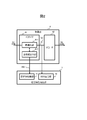
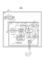
- FIG. 1 is a system configuration diagram according to the first embodiment.
- the vehicle 100 includes an ECU 1, a sensor 2, and a transmitter 3.
- the transmitter 3 may be built in the sensor 2.
- the ECU 1 and the transmitter 3 are connected by a transmission line L.
- the sensor 2 is, for example, a camera, and transmits a photographed image, which is an image obtained by photographing, that is, sensor data S0 to the ECU 1 via the transmitter 3.
- the transmitter 3 is, for example, an electronic control unit.
- the transmitter 3 serializes the sensor data S0 output from the sensor 2 and serially transmits the sensor data S0 to the ECU 1 via the transmission line L.
- the electrical signal output from the transmitter 3 to the transmission line L will be referred to as a signal S1.
- the transmission line L has a predetermined length, for example, a length of several meters to several tens of meters. Due to the frequency characteristic of the transmission line L, when the signal S1 output from the transmitter 3 is input to the receiver 4, It changes to the signal S2.
- the frequency characteristics of the transmission line L change depending on the environmental conditions of the transmission line L and other conditions. Environmental conditions include temperature, humidity, acceleration, and the like. Other conditions are that the transmission line L receives the force of compression and expansion, and that the self impedance changes due to deformation.
- the ECU 1 includes a receiver 4, a trajectory planning unit 5, an actuator control unit 6, and a diagnosis unit 16.
- the diagnosis unit 16 includes a transmission characteristic extraction unit 7, a determination unit 8, a storage unit 9, a collection unit 10, and a result holding unit 11.
- the ECU 1 may be realized by any of a microcomputer, an ASIC, and a logic circuit, or may be realized by a plurality of combinations, for example, a combination of a microcomputer and a logic circuit.
- the receiver 4 has a known equalizer function.
- the receiver 4 combines the sensor data S0 from the signal S2 received from the transmitter 3 via the transmission line L, and outputs the combined sensor data S0 to the trajectory planning unit 5.
- the receiver 4 outputs the compensation parameter 300 of the built-in equalizer to the transmission characteristic extraction unit 7.
- the compensation parameter 300 and the code S3 will be described later.
- the track planning unit 5 uses the sensor data S0 received from the receiver 4 to calculate the track on which the vehicle 100 will travel, and outputs the calculated track to the actuator control unit 6 and the determination unit 8.
- the trajectory planning unit 5 detects, for example, an obstacle existing around the vehicle 100 from the sensor data S0, and calculates the trajectory of the vehicle 100 so as to avoid the detected obstacle.
- the actuator control unit 6 controls the vehicle 100 so that the vehicle 100 travels along the trajectory of the vehicle 100 output by the trajectory planning unit 5.
- the actuator control unit 6 controls the vehicle 100 by outputting an operation command to an engine, a braking device, and a steering mechanism (not shown), for example.
- the actuator control unit 6 controls the vehicle 100 so as to follow the trajectory output by the trajectory planning unit 5 as described above, but "abnormal". In the case of, the vehicle 100 is stopped safely.
- the determination unit 8 refers to the parameter correspondence information 91 stored in the storage unit 9 and determines the transmission state corresponding to the compensation parameter 300 output from the transmission characteristic extraction unit 7 and the environment information output from the collection unit 10. To do.
- the determination unit 8 outputs the determined transmission state to the actuator control unit 6 and the result holding unit 11.
- the storage unit 9 stores parameter correspondence information 91.
- the parameter correspondence information 91 is a table showing the relationship between the compensation parameter 300, the environment information, and the transmission state.
- the parameter correspondence information 91 is created in advance based on experiments and the like.
- the parameter correspondence information 91 only needs to store the information indicating the relationship between the compensation parameter 300, the environment information, and the transmission state, and need not store the information in the table format.
- the collection unit 10 collects environmental information inside and outside the vehicle 100 using a sensor (not shown) mounted on the vehicle 100.
- the environmental information is, for example, temperature, humidity, vibration and the like.
- the collection unit 10 outputs the collected environmental information to the determination unit 8.
- the result holding unit 11 holds the judgment result output by the judgment unit 8 and outputs it at a predetermined timing.
- the predetermined timing may be a predetermined time interval or a timing at which the determination result output by the determination unit 8 has changed.
- the output destination to which the result holding unit 11 outputs the determination result may be a device (not shown) mounted on the vehicle 100, or may be outside the vehicle 100.
- the ECU 1 may include a wireless communication module, or the device other than the ECU 1 mounted on the vehicle 100 may include the wireless communication module. ..
- FIG. 2 is a functional configuration diagram of the receiver 4 and the transmission characteristic extraction unit 7.
- the receiver 4 includes an equalizer 41 and a decoder 42.
- the equalizer 41 includes an optimization unit 411 and a set value output unit 412.
- the optimization unit 411 receives the signal S2 that has passed through the transmission line L, and compensates for the loss due to the frequency characteristic of the transmission line L and outputs the compensated signal S3 to the decoder 42. More specifically, the optimizing unit 411 determines the compensation parameter 300 for executing compensation and executes compensation using the compensation parameter 300. By this compensation, the signal S2 is compensated for the signal S3. It is desirable that the signal S3 be equal to the signal S1 before being affected by the transmission on the transmission line L.
- the compensation parameter 300 is, for example, the presence or absence of compensation for each frequency component and the intensity of compensation.
- DFE Decision Feedback Equalizer
- the compensation parameter 300 has 8 bits, that is, there are 256 types of compensation patterns that are 2 8 powers.
- the number of bits of the compensation parameter 300 is not limited to 8 bits.
- the value of the compensation parameter 300 is described as a scalar value, that is, 00000000 to 11111111 for convenience, but the magnitude of the scalar value has no meaning.
- the frequency characteristic of the transmission line L is changed and the state of the transmission line L is deteriorated due to the physical compression of the transmission line L or the temperature rise, the degree of deterioration and the scalar value of the compensation parameter 300 are large or small. There is no correlation with. This is because the presence or absence of compensation for a certain frequency and the digit of the scalar value to which the compensation intensity is assigned are arbitrary.
- the set value output unit 412 outputs the compensation parameter 300 determined by the optimization unit 411 to the transmission characteristic extraction unit 7.
- the decoder 42 deserializes the compensated signal S3 output from the equalizer 41 and outputs the sensor data S0 to the trajectory planning unit 5.
- the transmission characteristic extraction unit 7 includes a set value collection unit 71 and a BER calculation unit 72.
- the set value collection unit 71 acquires the compensation parameter 300 from the set value output unit 412 of the receiver 4.
- the BER calculator 72 calculates a bit error rate (Bit Error Rate) for the compensated signal S3 output from the equalizer 41.
- the BER calculator 72 detects a bit error using a predetermined rule, for example, the value of a parity bit in a specific signal pattern, based on a known serialization method of the transmitter 3, and calculates the error occurrence rate.
- the calculation results of the set value collection unit 71 and the BER calculation unit 72 are output to the determination unit 8.
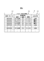
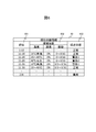
- FIG. 3 is a diagram showing an example of the parameter correspondence information 91.
- the parameter correspondence information 91 shown in FIG. 3 has fields of a compensation parameter 911, environment information 912, and a transmission state 913.
- the value of the compensation parameter 300 calculated by the optimizing unit 411 is stored bit by bit. Although only “000” and “001” are shown in FIG. 3 due to space limitations, all eight combinations are recorded.
- the field of the environment information 912 stores temperature, humidity, and vibration, which are environment information collected by the collection unit 10. Each of the temperature, the humidity, and the vibration may store a single value like the humidity in the example of FIG. 3, or a value having a range like the temperature or the vibration in the example of FIG. Good.
- Information indicating the transmission status of the transmission path L is stored in the field of the transmission status 913.
- the value of the transmission state 913 is set in advance for each combination of the compensation parameter 911 and the environment information 912. That is, even if the values of the compensation parameters 911 are the same, if the values of the environment information 912 are different, different values may be set for the transmission state 913.
- the transmission state 913 can take five states: normal, warning 1, warning 2, warning 3, and abnormal. However, the number of states is an example, and at least two states may be included.
- the ECU 1 is mounted on the vehicle 100.
- the ECU 1 determines the state of the transmission line L, the receiver 4 that receives the data signal S2 transmitted via the transmission line L mounted on the vehicle 100, the collection unit 10 that collects the environmental information of the vehicle 100, and the transmission line L.
- the receiver 4 includes an equalizer 41 for compensating the data signal S2, the equalizer 41 calculates a compensation parameter 300 for compensating the data signal, and the determiner 8 determines the compensation parameter 300 and
- the state of the transmission line L is determined based on the environment information. Therefore, the ECU 1 can determine the state of the transmission line L at low cost.
- the ECU 1 includes the storage unit 9 that stores the compensation parameter 300, the environment information, and the parameter correspondence information 91 indicating the relationship between the states of the transmission paths.
- the determination unit 8 refers to the parameter correspondence information 91 to determine the state of the transmission path based on the compensation parameter 300 and the environment information. Therefore, the ECU 1 can determine the state of the transmission line L at low cost by referring to the parameter correspondence information 91 stored in the storage unit 9.
- the parameter correspondence information 91 may include the bit error rate calculated by the BER calculation unit 72. That is, the parameter correspondence information 91 in this modified example is a table showing the relationship among the compensation parameter 300, the bit error rate, the environment information, and the transmission state. In this case, the transmission characteristic extraction unit 7 also outputs the calculated bit error rate to the determination unit 8.
- the determination unit 8 refers to the parameter correspondence information 91 and identifies the transmission state based on the compensation parameter 300, the bit error rate, and the environment information.
- the environmental information may include at least one of temperature, humidity, and vibration. Further, the environmental information may include other measurable values such as the amount of ultraviolet rays.
- FIGS. 4 to 6 A second embodiment of an ECU that is an electronic control device according to the present invention will be described with reference to FIGS. 4 to 6.
- the same components as those of the first embodiment are designated by the same reference numerals, and the differences are mainly described.
- the points that are not particularly described are the same as those in the first embodiment.
- the present embodiment is different from the first embodiment mainly in that the compensation parameters 300 are ranked.
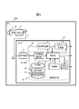
- FIG. 4 is a system configuration diagram in the second embodiment.
- the information stored in the storage unit 9 of the ECU 1A according to the second embodiment is different from that of the ECU 1 according to the first embodiment.
- storage unit 9 stores ranking information 92 and ranking status information 93.
- the order information 92 is information that allows the compensation parameters 300 to be rearranged in the order of the magnitude of the influence on the transmission path L.
- the compensation parameters 300 are arranged in the order in which the influence on the transmission line L from the outside is small, and will be referred to as the “order of compensation parameters”.
- the rank of the compensation parameter 300 is the first rank, it means that the transmission line L is hardly affected by the outside.
- the rank status information 93 is information indicating the relationship between the rank of the compensation parameter 300, the environment information, and the status of the transmission path.
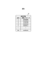
- FIG. 5 is a diagram showing an example of the order information 92.
- the rank is from 1 to 256.
- the correspondence between the rank and the compensation parameter 300 is shown, and the first rank, the second rank, the third rank,... Are shown from the top.
- FIG. 6 is a diagram showing an example of the ranking status information 93.
- the rank status information 93 shown in FIG. 6 has fields for rank 931, environment information 932, and transmission status 933.
- the rank value of the compensation parameter 300 is stored in the rank 931 field.
- a plurality of ranks may be stored, and for example, as shown in the first record, the first to tenth ranks may be collectively described.
- the fields of the environment information 932 and the transmission status 933 are the same as those of the environment information 912 and the transmission status 913 of the parameter correspondence information 91 in the first embodiment, and therefore the description thereof will be omitted.
- the determination unit 8 refers to the rank information 92 and the rank status information 93 to judge the status of the transmission path based on the compensation parameter 300 and the environment information. That is, the determination unit 8 refers to the order information 92 and the order status information 93 instead of the parameter correspondence information 91 in the first embodiment.
- the ECU 1A includes the storage unit 9 in which the ranking information 92 and the ranking state information 93 are stored.
- the order information 92 is information that allows the values of the compensation parameter 300 to be rearranged in order of the magnitude of the influence on the transmission line L.
- the rank status information 93 is information indicating the relationship among the rank, environment information, and the status of the transmission path.
- the determination unit 8 refers to the rank information 92 and the rank status information 93 to judge the status of the transmission path L based on the compensation parameter 300 and the environment information.
- the determination unit 8 may change the determination on the state of the transmission path L according to the speed of the vehicle 100A. For example, when the vehicle 100A is traveling at high speed, the risk of a trivial problem causing a large problem is higher than that at low speed traveling, and therefore the determination unit 8 severely determines the abnormality. In other words, the determination unit 8 widens the range that is determined to be abnormal during high speed traveling. Specifically, the determination unit 8 offsets the rank of the compensation parameter 300 according to the speed of the vehicle 100A. It should be noted that offsetting the rank is equivalent to changing the threshold value for judging the transmission state.
- ⁇ Offset means changing the ranking, and the amount of movement is arbitrary. However, it does not fluctuate beyond the default minimum and maximum values. For example, if the rank before the offset is "5th" and the offset amount is "-10", the minimum rank "1st" is set instead of "-5th". For example, the determination unit 8 offsets the rank by "-10" when the speed is less than 10 km/h, does not change the rank when the speed is 10 km/h or more and less than 20 km/h, and does not change when the speed is 20 km/h or more. When the speed is less than 30 km, the order is offset by "+10", and when the speed is 30 km/h or more and less than 40 km/h, the order is offset by "+20". The determination unit 8 continues to increase the offset amount each time the speed of the vehicle 100A increases.
- the collection unit 10 collects speed information of the vehicle 100A.
- the determination unit 8 offsets the ranking according to the speed of the vehicle 100A. Therefore, the state of the transmission line can be evaluated according to the situation.
- the determination unit 8 may determine the state of the transmission line L based on the transition of the order information. For example, according to the ranking status information 93, if the transmission status is determined to be “abnormal” when the ranking reaches 100th under a certain environmental condition, and if the ranking gradually increases under that environmental condition, the ranking is 100th. The transmission status may be determined to be “abnormal” before the change.
- the determination unit 8 determines the state of the transmission path based on the transition of the ranking information. Therefore, it is possible to detect the precursor of the abnormality and detect it before the abnormality occurs.
- FIG. 7 A third embodiment of an ECU that is an electronic control device according to the present invention will be described with reference to FIG. 7.
- the same components as those of the first embodiment are designated by the same reference numerals, and the differences are mainly described.
- the points that are not particularly described are the same as those in the first embodiment.
- the present embodiment differs from the first embodiment mainly in that a reporting level selection unit is further provided.
- FIG. 7 is a system configuration diagram of the ECU 1B in the third embodiment.
- the ECU 1B further includes a reporting level selection unit 31 in addition to the configuration of the first embodiment.
- the report level selection unit 31 reports to the outside of the ECU 1B only when the output of the determination unit 8 is above a certain level.
- the report is to notify by communication. For example, when the report level of the report level selection unit 31 is set to "warning 3", the report level selection unit 31 reports when the output of _ is "warning 3" or "abnormal", and “normal”. , "Warning 1", and "warning 2" are not reported.
- the report level selection unit 31 may change the output destination according to the content of the report.
- the output destination is set in advance for each report content. For example, when the transmission status is "warning 3", a certain device X is reported, and when the transmission state is "abnormal", another device Y is reported.
- the number of output destinations may be changed according to the transmission status.
- the ECU 1B includes the report level selection unit 31 that reports the state of the transmission path determined by the determination unit 8.
- the report level selection unit 31 changes the report destination according to the state of the transmission path.
- FIG. 1 A fourth embodiment of an ECU that is an electronic control device according to the present invention will be described with reference to FIG.
- the same components as those of the first embodiment are designated by the same reference numerals, and the differences are mainly described.
- the points that are not particularly described are the same as those in the first embodiment.
- This embodiment differs from the first embodiment mainly in that the ECU includes an external communication unit.
- FIG. 8 is a system configuration diagram of the ECU 1C in the present embodiment.
- the ECU 1C further includes an external world communication unit 41 in addition to the configuration of the first embodiment.
- the external communication unit 41 is a communication module compatible with a wireless communication standard such as 4G.
- the external communication unit 41 communicates with a preset server 43 outside the vehicle.
- the external communication unit 41 transmits to the server 43 the traveling information of the vehicle 100C such as the environment information collected by the collection unit 10, the compensation parameter 300, and the speed. Further, the external world communication unit 41 overwrites the information of the parameter correspondence information 91 transmitted from the server 43 in the storage unit 9 and updates the parameter correspondence information 91.
- the server 43 collects environment information, compensation parameters 300, and vehicle traveling information from a plurality of ECUs 1C, and sets an appropriate transmission state value of the parameter correspondence information 91 for each condition.
- the value of the transmission state may be set by automatic processing, or may be set by the operator of the server 43.
- the ECU 1C transmits the environment information, the state of the transmission path L determined by the determination unit 8, and the speed information of the vehicle 100 to the outside of the vehicle 100C, and receives the parameter correspondence information 91 from the outside of the vehicle 100C.
- the communication unit 41 is provided. Therefore, the ECU 1C can improve the parameter correspondence information 91 by using the server 43 existing outside the vehicle 100.
- the parameter correspondence information 91 stored in the storage unit 9 may be rewritten from the server 43 not via the external communication unit 41, but during maintenance or the like without using the external communication unit 41.
- the ECU 1C may include a receiver that constitutes a satellite navigation system, for example, a GPS receiver.
- the external communication unit 41 may transmit the position information and time information of the vehicle 100C to the server 43 together with the environment information, the compensation parameter 300, and the travel information described above.
- the external communication unit 41 of the ECU 1C may receive the ranking status information 93 instead of receiving the parameter correspondence information 91 from the server 43.
- the order information 92 does not need to be received because it does not change.
- FIG. 1 A fifth embodiment of an ECU that is an electronic control device according to the present invention will be described with reference to FIG.
- the same components as those of the first embodiment are designated by the same reference numerals, and the differences are mainly described.
- the points that are not particularly described are the same as those in the first embodiment.
- This embodiment differs from the first embodiment mainly in that a plurality of sets of sensors and transmission lines are provided.
- the present embodiment is based on the following idea. That is, the plurality of transmission lines mounted on the vehicle should be similarly affected by the environment, and the tendency of the influence is expected to be substantially the same. If the plurality of transmission lines are affected differently, it is assumed that some abnormality is present in the transmission line, for example, only one transmission line is compressed.
- FIG. 9 is a system configuration diagram of the ECU 1D according to the fifth embodiment.
- vehicle 100D includes first sensor 2a, second sensor 2b, first transmitter 3a, second transmitter 3b, and ECU 1D.
- the sensor information acquired by the first sensor 2a is transmitted to the first transmitter 3a and further transmitted to the ECU 1D via the first transmission line L1.
- the sensor information acquired by the second sensor 2b is transmitted to the second transmitter 3b and further transmitted to the ECU 1D via the second transmission line L2.
- the lengths of the first transmission line L1 and the second transmission line L2 do not have to be the same.
- the ECU 1D does not have to include the determination unit 8 and the collection unit 10. Further, in the present embodiment, the parameter correspondence information 91 may not be stored in the storage unit 9. In the present embodiment, ECU 1D includes a storage unit 62a and a storage unit 62b instead of storage unit 9.
- the transmission characteristic extraction unit 7a outputs the collected compensation parameters 300 to the storage unit 62a and the change amount calculation unit 61a.
- the change amount calculation unit 61a calculates the difference between the immediately preceding compensation parameter 300 stored in the storage unit 62a and the latest compensation parameter 300 output by the transmission characteristic extraction unit 7a, that is, the change amount of the compensation parameter 300.
- the change amount calculation unit 61a outputs the calculated change amount to the comparator 63.
- the transmission characteristic extraction unit 7b outputs the collected compensation parameters 300 to the storage unit 62b and the change amount calculation unit 61b.
- the change amount calculation unit 61b calculates the difference between the immediately preceding compensation parameter 300 stored in the storage unit 62b and the latest compensation parameter 300 output by the transmission characteristic extraction unit 7b, that is, the change amount of the compensation parameter 300.
- the change amount calculation unit 61b outputs the calculated change amount to the comparator 63.
- the comparator 63 compares the change amount output by the change amount calculating unit 61a with the change amount output by the change amount calculating unit 61b.
- the comparator 63 determines normal when both are the same or the difference is within a predetermined threshold, and determines abnormal when the two are different or the difference is larger than the predetermined threshold.
- the comparator 63 outputs the determination result to the outside of the actuator control unit 6, the result holding unit 11, and the ECU 1D.
- the ECU 1D detects an abnormality in the transmission path by comparing changes in frequency characteristics of a plurality of transmission paths provided in the vehicle 100D. Therefore, it is possible to detect the abnormality of the transmission path without providing any of the parameter correspondence information 91, the rank information 92, and the rank status information 93.
Landscapes
- Engineering & Computer Science (AREA)
- Computer Networks & Wireless Communication (AREA)
- Signal Processing (AREA)
- Quality & Reliability (AREA)
- Physics & Mathematics (AREA)
- Electromagnetism (AREA)
- Power Engineering (AREA)
- Health & Medical Sciences (AREA)
- Computing Systems (AREA)
- General Health & Medical Sciences (AREA)
- Medical Informatics (AREA)
- Mechanical Engineering (AREA)
- Arrangements For Transmission Of Measured Signals (AREA)
- Small-Scale Networks (AREA)
Abstract
電子制御装置は車両に搭載され、車両に搭載される伝送路を介して伝送されたデータ信号を受信する受信部と、車両の環境情報を取得する環境情報取得部と、伝送路の状態を判定する判定部とを備え、受信部は、データ信号を補償するイコライザを備え、イコライザは、データ信号を補償するための補償パラメータを算出し、判定部は、補償パラメータおよび環境情報に基づいて、伝送路の状態を判定する。
Description
本発明は、電子制御装置、および判定方法に関する。
車両内で扱う電子データは増加し続けており、大量のデータを高速に送受信する需要が増えている。走行する車両内ではデータの伝送路へ悪影響を及ぼす要因が多数存在する。シールドにより悪影響を緩和できるが全ての悪影響を排除することは困難であり、また材料や実装のコストの問題もあるため、伝送路の状態を判定し判定結果に応じた処理を施すことが求められる。特許文献1には、有線又は無線による伝送路を介して構成される通信システムの劣化を診断する劣化診断部と、前記劣化診断部の診断結果に基づいて、前記通信システムの劣化を予測する劣化予測部とを備えることを特徴とする通信機が開示されている。
特許文献1に記載されている発明では、診断のコストが高い。
本発明の第1の態様による電子制御装置は、車両に搭載される電子制御装置であって、前記車両に搭載される伝送路を介して伝送されたデータ信号を受信する受信部と、前記車両の環境情報を取得する収集部と、前記伝送路の状態を判定する判定部とを備え、前記受信部は、前記データ信号を補償するイコライザを備え、前記イコライザは、前記データ信号を補償するための補償パラメータを算出し、前記判定部は、前記補償パラメータおよび前記環境情報に基づいて、前記伝送路の状態を判定する。
本発明の第2の態様による判定方法は、車両に搭載される電子制御装置が実行する判定方法であって、前記電子制御装置は、前記車両に搭載される伝送路を介して伝送されたデータ信号を受信する受信部を備え、前記受信部は、前記データ信号を補償するイコライザを備え、前記車両の環境情報を取得することと、前記イコライザは、前記データ信号を補償するための補償パラメータを算出することと、前記補償パラメータおよび前記環境情報に基づいて、前記伝送路の状態を判定することとを含む。
本発明の第2の態様による判定方法は、車両に搭載される電子制御装置が実行する判定方法であって、前記電子制御装置は、前記車両に搭載される伝送路を介して伝送されたデータ信号を受信する受信部を備え、前記受信部は、前記データ信号を補償するイコライザを備え、前記車両の環境情報を取得することと、前記イコライザは、前記データ信号を補償するための補償パラメータを算出することと、前記補償パラメータおよび前記環境情報に基づいて、前記伝送路の状態を判定することとを含む。
本発明によれば、低コストで伝送路の状態を判定できる。上記した以外の課題、構成および効果は、以下の発明を実施するための形態の説明により明らかにされる。
以下、図面を参照して本発明の実施形態を説明する。以下の記載および図面は、本発明を説明するための例示であって、説明の明確化のため、適宜、省略および簡略化がなされている。本発明は、他の種々の形態でも実施する事が可能である。特に限定しない限り、各構成要素は単数でも複数でも構わない。
以下の説明では、「テーブル」、「リスト」、「キュー」等の表現にて各種情報を説明することがあるが、各種情報は、これら以外のデータ構造で表現されていてもよい。データ構造に依存しないことを示すために「XXテーブル」、「XXリスト」等を「XX情報」と呼ぶことがある。
また、以下の説明では、プログラムを実行して行う処理を説明する場合があるが、プログラムは、プロセッサ(例えばCPU、GPU)によって実行されることで、定められた処理を、適宜に記憶資源(例えばメモリ)および/またはインターフェースデバイス(例えば通信ポート)等を用いながら行うため、処理の主体がプロセッサとされてもよい。同様に、プログラムを実行して行う処理の主体が、プロセッサを有するコントローラ、装置、システム、計算機、ノードであってもよい。プログラムを実行して行う処理の主体は、演算部であれば良く、特定の処理を行う専用回路(例えばFPGAやASIC)を含んでいてもよい。
―第1の実施の形態―
以下、図1~図3を参照して、本発明に係る電子制御装置であるECUの第1の実施の形態を説明する。
以下、図1~図3を参照して、本発明に係る電子制御装置であるECUの第1の実施の形態を説明する。
(システム構成)
図1は、第1の実施の形態におけるシステム構成図である。車両100は、ECU1と、センサ2と、送信器3と、を備える。ただし送信器3はセンサ2に内蔵されてもよい。ECU1と送信器3とは伝送路Lにより接続される。センサ2はたとえばカメラであり、撮影して得られた画像である撮影画像、すなわちセンサデータS0を送信器3を介してECU1に送信する。送信器3はたとえば電子制御装置(Electronic Control Unit)である。送信器3は、センサ2から出力されたセンサデータS0をシリアル化し、伝送路Lを介してECU1にシリアル伝送する。以下では、送信器3が伝送路Lに出力する電気信号を信号S1と呼ぶ。
図1は、第1の実施の形態におけるシステム構成図である。車両100は、ECU1と、センサ2と、送信器3と、を備える。ただし送信器3はセンサ2に内蔵されてもよい。ECU1と送信器3とは伝送路Lにより接続される。センサ2はたとえばカメラであり、撮影して得られた画像である撮影画像、すなわちセンサデータS0を送信器3を介してECU1に送信する。送信器3はたとえば電子制御装置(Electronic Control Unit)である。送信器3は、センサ2から出力されたセンサデータS0をシリアル化し、伝送路Lを介してECU1にシリアル伝送する。以下では、送信器3が伝送路Lに出力する電気信号を信号S1と呼ぶ。
伝送路Lは所定の長さ、たとえば数m~数十mの長さを有し、伝送路Lの周波数特性により、送信器3が出力した信号S1は受信器4に入力される際には信号S2に変化する。また伝送路Lの周波数特性は、伝送路Lの環境条件やその他の条件により変化する。環境条件とは、温度、湿度、加速度などである。その他の条件とは、伝送路Lが圧縮伸長の力を受けることや、変形により自己インピーダンスが変化することである。
ECU1は、受信器4と、軌道計画部5と、アクチュエータ制御部6と、診断部16とを備える。診断部16は、伝送特性抽出部7と、判定部8と、記憶部9と、収集部10と、結果保持部11とを備える。ECU1は、マイコン、ASIC、論理回路のいずれにより実現されてもよいし、複数の組み合わせ、たとえばマイコンと論理回路の組み合わせにより実現されてもよい。
受信器4は公知のイコライザ機能を有する。受信器4は、伝送路Lを介して送信器3から受信した信号S2からセンサデータS0を複合して軌道計画部5に出力する。受信器4は、内蔵するイコライザの補償パラメータ300を伝送特性抽出部7に出力する。補償パラメータ300および符号S3については後述する。
軌道計画部5は、受信器4から受信するセンサデータS0を用いて、車両100がこれから走行する軌道を算出し、アクチュエータ制御部6および判定部8に出力する。軌道計画部5はたとえば、センサデータS0から車両100の周囲に存在する障害物を検出し、検出した障害物を避けるように車両100の軌道を算出する。
アクチュエータ制御部6は、軌道計画部5が出力する車両100の軌道に沿って車両100が走行するように車両100を制御する。アクチュエータ制御部6はたとえば、不図示のエンジン、制動装置、およびステアリング機構に動作指令を出力することで車両100を制御する。ただしアクチュエータ制御部6は、判定部8から出力される状態判定の結果が「正常」の場合は前述のとおり軌道計画部5が出力する軌道に沿うように車両100を制御するが、「異常」の場合は車両100を安全に停止させる。
伝送特性抽出部7の動作は後述する。判定部8は、記憶部9に格納されるパラメータ対応情報91を参照し、伝送特性抽出部7から出力される補償パラメータ300、および収集部10から出力される環境情報に対応する伝送状態を判定する。判定部8は、判定した伝送状態をアクチュエータ制御部6および結果保持部11に出力する。
記憶部9には、パラメータ対応情報91が格納される。パラメータ対応情報91は、補償パラメータ300、環境情報、および伝送状態の関係を示すテーブルである。パラメータ対応情報91は、実験などに基づきあらかじめ作成される。なおパラメータ対応情報91は補償パラメータ300、環境情報、および伝送状態の関係を示す情報が格納されていればよく、テーブル形式で情報が格納されていなくてもよい。
収集部10は、車両100に搭載される不図示のセンサを用いて車両100の内外の環境情報を収集する。環境情報とはたとえば、温度、湿度、振動などである。収集部10は、収集した環境情報を判定部8に出力する。
結果保持部11は、判定部8が出力する判定結果を保持し、所定のタイミングで出力する。所定のタイミングとは、予め定められた時間間隔でもよいし、判定部8が出力する判定結果が変化したタイミングでもよい。また結果保持部11が判定結果を出力する出力先は、車両100に搭載される不図示の装置であってもよいし、車両100の外部であってもよい。結果保持部11が判定結果を車両100の外部に出力する場合は、ECU1に無線通信モジュールが内蔵されてもよいし、ECU1以外の車両100に搭載される装置が無線通信モジュールを備えてもよい。
(受信器4および伝送特性抽出部7の詳細)
図2は、受信器4および伝送特性抽出部7の機能構成図である。受信器4は、イコライザ41およびデコーダ42を備える。イコライザ41は、最適化部411と、設定値出力部412とを備える。最適化部411は、伝送路Lを通過した信号S2を受信し、伝送路Lの周波数特性による損失を補い補償済み信号S3をデコーダ42に出力する。詳述すると、最適化部411は、補償を実行するための補償パラメータ300の決定、および補償パラメータ300を用いた補償の実行を行う。この補償により、信号S2が信号S3に補償される。信号S3は、伝送路Lによる伝送の影響を受ける前の信号S1と同等になることが望ましい。
図2は、受信器4および伝送特性抽出部7の機能構成図である。受信器4は、イコライザ41およびデコーダ42を備える。イコライザ41は、最適化部411と、設定値出力部412とを備える。最適化部411は、伝送路Lを通過した信号S2を受信し、伝送路Lの周波数特性による損失を補い補償済み信号S3をデコーダ42に出力する。詳述すると、最適化部411は、補償を実行するための補償パラメータ300の決定、および補償パラメータ300を用いた補償の実行を行う。この補償により、信号S2が信号S3に補償される。信号S3は、伝送路Lによる伝送の影響を受ける前の信号S1と同等になることが望ましい。
最適化部411による補償パラメータ300の決定は公知の手法、たとえばDFE(Decision Feedback Equalizer)を採用する。補償パラメータ300はたとえば、周波数成分ごとの補償の有無や補償の強度である。本実施の形態では、補償パラメータ300は8ビット、すなわち2の8乗である256とおりの補償パターンが存在するとして説明する。ただし補償パラメータ300のビット数は8ビットに限定されない。
なお本実施の形態では補償パラメータ300の値を便宜的にスカラー値、すなわち00000000~11111111で記載するが、そのスカラー値の大小に意味はない。たとえば、伝送路Lが物理的に圧迫されることや温度上昇することにより伝送路Lの周波数特性が変化し伝送路Lの状態は悪化するが、悪化の度合いと補償パラメータ300のスカラー値の大小に相関はない。ある周波数についての補償の有無や補償の強度をスカラー値の何桁目に割り当てるかは任意だからである。
設定値出力部412は、最適化部411が決定した補償パラメータ300を伝送特性抽出部7に出力する。デコーダ42は、イコライザ41が出力する補償済み信号S3をデシリアル化し、センサデータS0を軌道計画部5に出力する。
伝送特性抽出部7は、設定値収集部71と、BER算出部72とを備える。設定値収集部71は、受信器4の設定値出力部412から補償パラメータ300を取得する。BER算出部72は、イコライザ41が出力する補償済み信号S3を対象としてビットエラーレート(Bit Error Rate)を算出する。BER算出部72は、既知である送信器3のシリアル化手法に基づき、所定のルール、たとえば特定の信号パターンにおけるパリティビットの値を用いてビットエラーを検出し、エラーの発生率を算出する。設定値収集部71およびBER算出部72の計算結果は、判定部8に出力される。
(パラメータ対応情報91)
図3は、パラメータ対応情報91の一例を示す図である。図3に示すパラメータ対応情報91は、補償パラメータ911、環境情報912、および伝送状態913のフィールドを有する。補償パラメータ911のフィールドには、最適化部411が算出した補償パラメータ300の値が1ビットずつ格納される。図3では紙面の都合により「000」と「001」しか示していないが、全8とおりの組み合わせ全てが記録される。
図3は、パラメータ対応情報91の一例を示す図である。図3に示すパラメータ対応情報91は、補償パラメータ911、環境情報912、および伝送状態913のフィールドを有する。補償パラメータ911のフィールドには、最適化部411が算出した補償パラメータ300の値が1ビットずつ格納される。図3では紙面の都合により「000」と「001」しか示していないが、全8とおりの組み合わせ全てが記録される。
環境情報912のフィールドには、収集部10が収集する環境情報である、温度、湿度、および振動が格納される。温度、湿度、および振動のそれぞれは、図3の例における湿度のように単独の値が格納されてもよいし、図3の例における温度や振動のように範囲を持つ値が格納されてもよい。伝送状態913のフィールドには、伝送路Lの伝送状態を示す情報が格納される。伝送状態913の値は、補償パラメータ911と環境情報912の組み合わせごとにあらかじめ設定される。すなわち補償パラメータ911の値が同一であっても、環境情報912の値が異なる場合は、伝送状態913は異なる値が設定されることがある。
さらに環境情報912は、温度、湿度、および振動の組み合わせなので、補償パラメータ911、温度、および湿度が同一であっても振動が異なる場合には、伝送状態913は異なる値が設定されることがある。伝送状態913は、正常、警告1、警告2、警告3、異常の5つの状態をとりうる。ただし状態の数は一例であり、少なくとも2状態が含まれればよい。
上述した第1の実施の形態によれば、次の作用効果が得られる。
(1)ECU1は、車両100に搭載される。ECU1は、車両100に搭載される伝送路Lを介して伝送されたデータ信号S2を受信する受信器4と、車両100の環境情報を収集する収集部10と、伝送路Lの状態を判定する判定部8とを備え、受信器4は、データ信号S2を補償するイコライザ41を備え、イコライザ41は、データ信号を補償するための補償パラメータ300を算出し、判定部8は、補償パラメータ300および環境情報に基づいて、伝送路Lの状態を判定する。そのためECU1は、低コストに伝送路Lの状態を判定できる。
(1)ECU1は、車両100に搭載される。ECU1は、車両100に搭載される伝送路Lを介して伝送されたデータ信号S2を受信する受信器4と、車両100の環境情報を収集する収集部10と、伝送路Lの状態を判定する判定部8とを備え、受信器4は、データ信号S2を補償するイコライザ41を備え、イコライザ41は、データ信号を補償するための補償パラメータ300を算出し、判定部8は、補償パラメータ300および環境情報に基づいて、伝送路Lの状態を判定する。そのためECU1は、低コストに伝送路Lの状態を判定できる。
(2)ECU1は、補償パラメータ300、環境情報、および伝送路の状態の関係を示すパラメータ対応情報91が格納される記憶部9を備える。判定部8は、パラメータ対応情報91を参照することで、補償パラメータ300および環境情報に基づいて、伝送路の状態を判定する。そのためECU1は、記憶部9に格納されるパラメータ対応情報91を参照して低コストに伝送路Lの状態を判定できる。
(第1の実施の形態の変形例1)
パラメータ対応情報91に、BER算出部72が算出するビットエラーレートが含まれてもよい。すなわち、本変形例におけるパラメータ対応情報91は、補償パラメータ300、ビットエラーレート、環境情報、および伝送状態の関係を示すテーブルである。この場合は伝送特性抽出部7は、算出したビットエラーレートも判定部8に出力する。判定部8は、パラメータ対応情報91を参照し、補償パラメータ300、ビットエラーレート、および環境情報に基づき伝送状態を特定する。
パラメータ対応情報91に、BER算出部72が算出するビットエラーレートが含まれてもよい。すなわち、本変形例におけるパラメータ対応情報91は、補償パラメータ300、ビットエラーレート、環境情報、および伝送状態の関係を示すテーブルである。この場合は伝送特性抽出部7は、算出したビットエラーレートも判定部8に出力する。判定部8は、パラメータ対応情報91を参照し、補償パラメータ300、ビットエラーレート、および環境情報に基づき伝送状態を特定する。
(第1の実施の形態の変形例2)
環境情報は、温度、湿度、および振動の少なくとも1つが含まれていればよい。また環境情報に他の測定可能な値、たとえば紫外線量などが含まれてもよい。
環境情報は、温度、湿度、および振動の少なくとも1つが含まれていればよい。また環境情報に他の測定可能な値、たとえば紫外線量などが含まれてもよい。
―第2の実施の形態―
図4~図6を参照して、本発明に係る電子制御装置であるECUの第2の実施の形態を説明する。以下の説明では、第1の実施の形態と同じ構成要素には同じ符号を付して相違点を主に説明する。特に説明しない点については、第1の実施の形態と同じである。本実施の形態では、主に、補償パラメータ300に順位をつける点で、第1の実施の形態と異なる。
図4~図6を参照して、本発明に係る電子制御装置であるECUの第2の実施の形態を説明する。以下の説明では、第1の実施の形態と同じ構成要素には同じ符号を付して相違点を主に説明する。特に説明しない点については、第1の実施の形態と同じである。本実施の形態では、主に、補償パラメータ300に順位をつける点で、第1の実施の形態と異なる。
図4は、第2の実施の形態におけるシステム構成図である。第2の実施の形態におけるECU1Aは、第1の実施の形態におけるECU1と比較すると、記憶部9に格納される情報が異なる。本実施の形態では記憶部9には、順位情報92および順位状態情報93が格納される。順位情報92は、伝送路Lが受ける影響の大きさの順番で補償パラメータ300を並び替え可能な情報である。以下では、補償パラメータ300を伝送路Lが外部から受ける影響が小さい順番に並べたものを「補償パラメータの順位」と呼ぶ。たとえば、補償パラメータ300の順位が1位の場合には、伝送路Lが外部からほとんど影響を受けていないことを意味する。順位状態情報93は、補償パラメータ300の順位と環境情報と伝送路の状態との関係を示す情報である。
図5は、順位情報92の一例を示す図である。図5に示す例では、補償パラメータ300は8ビットなので順位は1~256位までである。図5に示す例では、順位と補償パラメータ300の対応が示されており、上から1位、2位、3位、・・・を示している。
図6は、順位状態情報93の一例を示す図である。図6に示す順位状態情報93は、順位931、環境情報932、および伝送状態933のフィールドを有する。順位931のフィールドには、補償パラメータ300の順位の値が格納される。ただし順位は複数格納してもよく、たとえば最初のレコードに示すように1位から10位までをまとめて記載してもよい。環境情報932および伝送状態933のフィールドは、第1の実施の形態におけるパラメータ対応情報91の環境情報912および伝送状態913と同様なので説明を省略する。
本実施の形態では判定部8は、順位情報92および順位状態情報93を参照することで、補償パラメータ300および環境情報に基づいて、伝送路の状態を判定する。すなわち判定部8は、第1の実施の形態におけるパラメータ対応情報91の代わりに順位情報92および順位状態情報93を参照する。
上述した第2の実施の形態によれば、次の作用効果が得られる。
(3)ECU1Aは、順位情報92および順位状態情報93が格納される記憶部9を備える。順位情報92とは、補償パラメータ300の値を伝送路Lが受ける影響の大きさの順位に並び替え可能な情報である。順位状態情報93とは、順位と環境情報と伝送路の状態との関係を示す情報である。判定部8は、順位情報92および順位状態情報93を参照することで、補償パラメータ300および環境情報に基づいて、伝送路Lの状態を判定する。
(3)ECU1Aは、順位情報92および順位状態情報93が格納される記憶部9を備える。順位情報92とは、補償パラメータ300の値を伝送路Lが受ける影響の大きさの順位に並び替え可能な情報である。順位状態情報93とは、順位と環境情報と伝送路の状態との関係を示す情報である。判定部8は、順位情報92および順位状態情報93を参照することで、補償パラメータ300および環境情報に基づいて、伝送路Lの状態を判定する。
(第2の実施の形態の変形例1)
判定部8は、車両100Aの速度に応じて伝送路Lの状態についての判定を変更してもよい。たとえば車両100Aが高速で走行している場合には、些細なことが大きな問題を引き起こす危険性が低速走行時に比べて高いため、判定部8は厳しめに異常を判断する。換言すると判定部8は、高速走行時には異常と判断する範囲を広くする。具体的には判定部8は、車両100Aの速度に応じて補償パラメータ300の順位をオフセットする。なお、順位をオフセットさせることは、伝送状態を判断する閾値を変化させることに等しい。
判定部8は、車両100Aの速度に応じて伝送路Lの状態についての判定を変更してもよい。たとえば車両100Aが高速で走行している場合には、些細なことが大きな問題を引き起こす危険性が低速走行時に比べて高いため、判定部8は厳しめに異常を判断する。換言すると判定部8は、高速走行時には異常と判断する範囲を広くする。具体的には判定部8は、車両100Aの速度に応じて補償パラメータ300の順位をオフセットする。なお、順位をオフセットさせることは、伝送状態を判断する閾値を変化させることに等しい。
オフセットとは、順位を変動させることであり、移動量は任意である。ただし既定の最小値と最大値を超えて変動することはない。たとえばオフセット前の順位が「5位」の場合にオフセット量が「-10」の場合には、「-5位」ではなく最小の順位である「1位」とする。たとえば判定部8は、速度が時速10km未満の場合には順位を「-10」オフセットし、速度が時速10km以上で時速20km未満の場合には順位を変動させず、速度が時速20km以上で時速30km未満の場合には順位を「+10」オフセットし、速度が時速30km以上で時速40km未満の場合には順位を「+20」オフセットする。判定部8はこれ以降も車両100Aの速度が速くなるごとにオフセット量を増やす。
本変形例によれば、次の作用効果が得られる。
(4)収集部10は車両100Aの速度情報を収集する。判定部8は、車両100Aの速度に応じて順位をオフセットする。そのため状況に応じて伝送路の状態を評価できる。
(4)収集部10は車両100Aの速度情報を収集する。判定部8は、車両100Aの速度に応じて順位をオフセットする。そのため状況に応じて伝送路の状態を評価できる。
(第2の実施の形態の変形例2)
判定部8は、順位情報の遷移に基づき伝送路Lの状態を判定してもよい。たとえば順位状態情報93によると、ある環境条件では順位が100位になると伝送状態が「異常」と判断される場合に、その環境条件で順位が徐々に増加している場合は、順位が100位になる前に伝送状態を「異常」と判断してもよい。
判定部8は、順位情報の遷移に基づき伝送路Lの状態を判定してもよい。たとえば順位状態情報93によると、ある環境条件では順位が100位になると伝送状態が「異常」と判断される場合に、その環境条件で順位が徐々に増加している場合は、順位が100位になる前に伝送状態を「異常」と判断してもよい。
本変形例によれば、次の作用効果が得られる。
(5)判定部8は、順位情報の遷移に基づき伝送路の状態を判定する。そのため異常の前兆をとらえて異常が発生する前に検出することができる。
(5)判定部8は、順位情報の遷移に基づき伝送路の状態を判定する。そのため異常の前兆をとらえて異常が発生する前に検出することができる。
―第3の実施の形態―
図7を参照して、本発明に係る電子制御装置であるECUの第3の実施の形態を説明する。以下の説明では、第1の実施の形態と同じ構成要素には同じ符号を付して相違点を主に説明する。特に説明しない点については、第1の実施の形態と同じである。本実施の形態では、主に、報告レベル選択部をさらに備える点で、第1の実施の形態と異なる。
図7を参照して、本発明に係る電子制御装置であるECUの第3の実施の形態を説明する。以下の説明では、第1の実施の形態と同じ構成要素には同じ符号を付して相違点を主に説明する。特に説明しない点については、第1の実施の形態と同じである。本実施の形態では、主に、報告レベル選択部をさらに備える点で、第1の実施の形態と異なる。
図7は、第3の実施の形態におけるECU1Bのシステム構成図である。ECU1Bは、第1の実施の形態における構成に加えて、報告レベル選択部31をさらに備える。報告レベル選択部31は、判定部8の出力がある一定のレベル以上の場合のみECU1Bの外部に報告する。報告とは、通信により通知することである。たとえば報告レベル選択部31の報告レベルが「警告3」に設定されている場合は、報告レベル選択部31は_の出力が「警告3」または「異常」の場合に報告を行い、「通常」、「警告1」、および「警告2」の場合には報告を行わない。
上述した第3の実施の形態によれば、予め定めたレベル以上に伝送路の状態が悪化した場合のみ報告することができる。
(第3の実施の形態の変形例)
報告レベル選択部31は、報告の内容に応じて出力先を変更してもよい。この場合には、報告の内容ごとに出力先があらかじめ設定される。たとえば伝送状態が「警告3」の場合にはある装置Xに報告を行い、「異常」の場合には別のある装置Yに報告を行う。なお、伝送状態に応じて出力先の数を変更してもよい。
報告レベル選択部31は、報告の内容に応じて出力先を変更してもよい。この場合には、報告の内容ごとに出力先があらかじめ設定される。たとえば伝送状態が「警告3」の場合にはある装置Xに報告を行い、「異常」の場合には別のある装置Yに報告を行う。なお、伝送状態に応じて出力先の数を変更してもよい。
本変形例によれば次の作用効果が得られる。
(6)ECU1Bは、判定部8が判定した伝送路の状態を報告する報告レベル選択部31を備える。報告レベル選択部31は、伝送路の状態に応じて報告先を変更する。
(6)ECU1Bは、判定部8が判定した伝送路の状態を報告する報告レベル選択部31を備える。報告レベル選択部31は、伝送路の状態に応じて報告先を変更する。
―第4の実施の形態―
図8を参照して、本発明に係る電子制御装置であるECUの第4の実施の形態を説明する。以下の説明では、第1の実施の形態と同じ構成要素には同じ符号を付して相違点を主に説明する。特に説明しない点については、第1の実施の形態と同じである。本実施の形態では、主に、ECUが外界通信部を備える点で、第1の実施の形態と異なる。
図8を参照して、本発明に係る電子制御装置であるECUの第4の実施の形態を説明する。以下の説明では、第1の実施の形態と同じ構成要素には同じ符号を付して相違点を主に説明する。特に説明しない点については、第1の実施の形態と同じである。本実施の形態では、主に、ECUが外界通信部を備える点で、第1の実施の形態と異なる。
図8は、本実施の形態におけるECU1Cのシステム構成図である。ECU1Cは、第1の実施の形態における構成に加えて外界通信部41をさらに備える。外界通信部41はたとえば4Gなどの無線通信規格に対応する通信モジュールである。外界通信部41は、あらかじめ設定された車外のサーバ43と通信を行う。外界通信部41は、収集部10が収集する環境情報、補償パラメータ300、および速度などの車両100Cの走行情報をサーバ43に送信する。また外界通信部41は、サーバ43から送信されるパラメータ対応情報91の情報を記憶部9に上書きし、パラメータ対応情報91を更新する。
サーバ43は、複数のECU1Cから環境情報、補償パラメータ300、車両の走行情報を収集し、条件ごとにより適切なパラメータ対応情報91の伝送状態の値を設定する。伝送状態の値は、自動処理により設定されてもよいし、サーバ43のオペレータが設定してもよい。
上述した第4の実施の形態によれば、次の作用効果が得られる。
(7)ECU1Cは、環境情報、判定部8が判定した伝送路Lの状態、および車両100の速度の情報を車両100Cの外部に送信し、車両100Cの外部からパラメータ対応情報91を受信する外界通信部41を備える。そのためECU1Cは、車両100の外部に存在するサーバ43を利用して、パラメータ対応情報91を改善することができる。
(7)ECU1Cは、環境情報、判定部8が判定した伝送路Lの状態、および車両100の速度の情報を車両100Cの外部に送信し、車両100Cの外部からパラメータ対応情報91を受信する外界通信部41を備える。そのためECU1Cは、車両100の外部に存在するサーバ43を利用して、パラメータ対応情報91を改善することができる。
(第4の実施の形態の変形例1)
記憶部9に格納されるパラメータ対応情報91は、サーバ43から外界通信部41を経由してではなく、メンテナンス時などに外界通信部41を経由せずに書き換えられてもよい。
記憶部9に格納されるパラメータ対応情報91は、サーバ43から外界通信部41を経由してではなく、メンテナンス時などに外界通信部41を経由せずに書き換えられてもよい。
(第4の実施の形態の変形例2)
ECU1Cは、衛星航法システムを構成する受信器、たとえばGPS受信器を備えてもよい。この場合に外界通信部41は、車両100Cの位置情報および時刻情報を、前述の環境情報、補償パラメータ300、および走行情報とともにサーバ43に送信してもよい。
ECU1Cは、衛星航法システムを構成する受信器、たとえばGPS受信器を備えてもよい。この場合に外界通信部41は、車両100Cの位置情報および時刻情報を、前述の環境情報、補償パラメータ300、および走行情報とともにサーバ43に送信してもよい。
(第4の実施の形態の変形例3)
ECU1Cの外界通信部41は、サーバ43からパラメータ対応情報91を受信する代わりに順位状態情報93を受信してもよい。なお、順位情報92は変化しないので受信する必要はない。
ECU1Cの外界通信部41は、サーバ43からパラメータ対応情報91を受信する代わりに順位状態情報93を受信してもよい。なお、順位情報92は変化しないので受信する必要はない。
―第5の実施の形態―
図9を参照して、本発明に係る電子制御装置であるECUの第5の実施の形態を説明する。以下の説明では、第1の実施の形態と同じ構成要素には同じ符号を付して相違点を主に説明する。特に説明しない点については、第1の実施の形態と同じである。本実施の形態では、主に、センサおよび伝送路が複数組備えられる点で、第1の実施の形態と異なる。
図9を参照して、本発明に係る電子制御装置であるECUの第5の実施の形態を説明する。以下の説明では、第1の実施の形態と同じ構成要素には同じ符号を付して相違点を主に説明する。特に説明しない点については、第1の実施の形態と同じである。本実施の形態では、主に、センサおよび伝送路が複数組備えられる点で、第1の実施の形態と異なる。
本実施の形態は次のアイデアに基づいている。すなわち、車両に搭載される複数の伝送路は同様に環境の影響を受けるはずであり、その影響の傾向は略同一であることが期待される。仮にその複数の伝送路が受ける影響が異なる場合には、伝送路に何らかの異常、たとえば一方の伝送路のみ圧迫されていることが想定される。
図9は第5の実施の形態におけるECU1Dのシステム構成図である。本実施の形態では、車両100Dは、第1センサ2a、第2センサ2b、第1送信器3a、第2送信器3b、およびECU1Dを備える。第1センサ2aが取得するセンサ情報は、第1送信器3aに送信され、さらに第1伝送路L1を介してECU1Dに送信される。第2センサ2bが取得するセンサ情報は、第2送信器3bに送信され、さらに第2伝送路L2を介してECU1Dに送信される。ただし第1伝送路L1および第2伝送路L2の長さは同一でなくてもよい。
本実施の形態では、ECU1Dは、判定部8および収集部10を備えなくてもよい。また本実施の形態では記憶部9にパラメータ対応情報91が格納されなくてよい。なお本実施の形態ではECU1Dは、記憶部9の代わりに記憶部62aと記憶部62bとを備える。
伝送特性抽出部7aは、収集した補償パラメータ300を記憶部62aおよび変化量算出部61aに出力する。変化量算出部61aは、記憶部62aに記憶されている直前の補償パラメータ300と、伝送特性抽出部7aが出力する最新の補償パラメータ300との差、すなわち補償パラメータ300の変化量を算出する。変化量算出部61aは、算出した変化量を比較器63に出力する。
伝送特性抽出部7bは、収集した補償パラメータ300を記憶部62bおよび変化量算出部61bに出力する。変化量算出部61bは、記憶部62bに記憶されている直前の補償パラメータ300と、伝送特性抽出部7bが出力する最新の補償パラメータ300との差、すなわち補償パラメータ300の変化量を算出する。変化量算出部61bは、算出した変化量を比較器63に出力する。
比較器63は、変化量算出部61aが出力する変化量と、変化量算出部61bが出力する変化量とを比較する。比較器63は両者が同一、または差が所定の閾値以内の場合は正常と判断し、両者に差異がある、またはその差が所定の閾値より大きい場合には異常と判断する。比較器63は、判断結果をアクチュエータ制御部6、結果保持部11、およびECU1Dの外部に出力する。
上述した第5の実施の形態によれば、次の作用効果が得られる。ECU1Dは、車両100Dに備えられる複数の伝送路の周波数特性の変化を比較することで伝送路の異常を検出する。そのためパラメータ対応情報91、順位情報92、および順位状態情報93のいずれを備えることなく伝送路の異常を検出できる。
上述した各実施の形態および変形例は、それぞれ組み合わせてもよい。上記では、種々の実施の形態および変形例を説明したが、本発明はこれらの内容に限定されるものではない。本発明の技術的思想の範囲内で考えられるその他の態様も本発明の範囲内に含まれる。
次の優先権基礎出願の開示内容は引用文としてここに組み込まれる。
日本国特許出願2019-22025(2019年2月8日出願)
日本国特許出願2019-22025(2019年2月8日出願)
1、1A、1B、1C、1D、1E …ECU
100、100A、100B、100C、100D、100E …車両
4…受信器
8…判定部
9…記憶部
10…収集部
91…パラメータ対応情報
92…順位情報
93…順位状態情報
300…補償パラメータ
411…最適化部
412…設定値出力部
911…補償パラメータ
912…環境情報
913…伝送状態
931…順位
932…環境情報
933…伝送状態
L、L1、L2…伝送路
100、100A、100B、100C、100D、100E …車両
4…受信器
8…判定部
9…記憶部
10…収集部
91…パラメータ対応情報
92…順位情報
93…順位状態情報
300…補償パラメータ
411…最適化部
412…設定値出力部
911…補償パラメータ
912…環境情報
913…伝送状態
931…順位
932…環境情報
933…伝送状態
L、L1、L2…伝送路
Claims (9)
- 車両に搭載される電子制御装置であって、
前記車両に搭載される伝送路を介して伝送されたデータ信号を受信する受信部と、
前記車両の環境情報を取得する収集部と、
前記伝送路の状態を判定する判定部とを備え、
前記受信部は、前記データ信号を補償するイコライザを備え、
前記イコライザは、前記データ信号を補償するための補償パラメータを算出し、
前記判定部は、前記補償パラメータおよび前記環境情報に基づいて、前記伝送路の状態を判定する電子制御装置。 - 請求項1に記載の電子制御装置において、
前記補償パラメータ、前記環境情報、および前記伝送路の状態の関係を示すパラメータ対応情報が格納される記憶部をさらに備え、
前記判定部は、前記パラメータ対応情報を参照することで、前記補償パラメータおよび前記環境情報に基づいて、前記伝送路の状態を判定する電子制御装置。 - 請求項1に記載の電子制御装置において、
順位情報および順位状態情報が格納される記憶部をさらに備え、
前記順位情報とは、前記補償パラメータの値を前記伝送路が受ける影響の大きさの順位に並び替え可能な情報であり、
前記順位状態情報とは、前記順位と前記環境情報と前記伝送路の状態との関係を示す情報であり、
前記判定部は、前記順位情報および前記順位状態情報を参照することで、前記補償パラメータおよび前記環境情報に基づいて、前記伝送路の状態を判定する電子制御装置。 - 請求項3に記載の電子制御装置において、
前記収集部は前記車両の速度情報を収集し、
前記判定部は、前記車両の速度に応じて前記順位をオフセットする電子制御装置。 - 請求項1に記載の電子制御装置において、
前記判定部が判定した前記伝送路の状態を報告する報告部をさらに備え、
前記報告部は、前記伝送路の状態に応じて報告先を変更する電子制御装置。 - 請求項2に記載の電子制御装置において、
前記環境情報、前記判定部が判定した前記伝送路の状態、および前記車両の速度の情報を前記車両の外部に送信し、前記車両の外部から前記パラメータ対応情報を受信する外界通信部をさらに備える電子制御装置。 - 請求項3に記載の電子制御装置において、
前記環境情報、前記判定部が判定した前記伝送路の状態、および前記車両の速度の情報を前記車両の外部に送信し、前記車両の外部から前記順位状態情報を受信する外界通信部をさらに備える電子制御装置。 - 請求項3に記載の電子制御装置において、
前記判定部は、前記順位情報の遷移に基づき前記伝送路の状態を判定する電子制御装置。 - 車両に搭載される電子制御装置が実行する判定方法であって、
前記電子制御装置は、
前記車両に搭載される伝送路を介して伝送されたデータ信号を受信する受信部を備え、
前記受信部は、前記データ信号を補償するイコライザを備え、
前記車両の環境情報を取得することと、
前記イコライザは、前記データ信号を補償するための補償パラメータを算出することと、
前記補償パラメータおよび前記環境情報に基づいて、前記伝送路の状態を判定することとを含む判定方法。
Priority Applications (2)
| Application Number | Priority Date | Filing Date | Title |
|---|---|---|---|
| CN202080012753.8A CN113453961B (zh) | 2019-02-08 | 2020-02-07 | 电子控制装置、判定方法 |
| US17/428,095 US11750424B2 (en) | 2019-02-08 | 2020-02-07 | Electronic control unit and determination method |
Applications Claiming Priority (2)
| Application Number | Priority Date | Filing Date | Title |
|---|---|---|---|
| JP2019-022025 | 2019-02-08 | ||
| JP2019022025A JP7136716B2 (ja) | 2019-02-08 | 2019-02-08 | 電子制御装置、判定方法 |
Publications (1)
| Publication Number | Publication Date |
|---|---|
| WO2020162628A1 true WO2020162628A1 (ja) | 2020-08-13 |
Family
ID=71947480
Family Applications (1)
| Application Number | Title | Priority Date | Filing Date |
|---|---|---|---|
| PCT/JP2020/004979 Ceased WO2020162628A1 (ja) | 2019-02-08 | 2020-02-07 | 電子制御装置、判定方法 |
Country Status (4)
| Country | Link |
|---|---|
| US (1) | US11750424B2 (ja) |
| JP (1) | JP7136716B2 (ja) |
| CN (1) | CN113453961B (ja) |
| WO (1) | WO2020162628A1 (ja) |
Families Citing this family (1)
| Publication number | Priority date | Publication date | Assignee | Title |
|---|---|---|---|---|
| JP7449785B2 (ja) * | 2020-06-17 | 2024-03-14 | 日立Astemo株式会社 | 電子制御装置、判定方法 |
Citations (4)
| Publication number | Priority date | Publication date | Assignee | Title |
|---|---|---|---|---|
| JPH10124766A (ja) * | 1996-10-23 | 1998-05-15 | Nittan Co Ltd | 環境監視システムおよび異常検出方法および異常検出装置 |
| JP2002280936A (ja) * | 2001-03-16 | 2002-09-27 | Hitachi Kokusai Electric Inc | 自動等化器の異常検出方法 |
| JP2016163117A (ja) * | 2015-02-27 | 2016-09-05 | 株式会社デンソー | 信号歪み補償回路 |
| JP2017092621A (ja) * | 2015-11-06 | 2017-05-25 | 矢崎総業株式会社 | 通信機 |
Family Cites Families (12)
| Publication number | Priority date | Publication date | Assignee | Title |
|---|---|---|---|---|
| JP5135767B2 (ja) * | 2006-11-09 | 2013-02-06 | ソニー株式会社 | データ受信装置 |
| JP4843800B2 (ja) * | 2007-07-20 | 2011-12-21 | 富士通株式会社 | 信号伝送装置及び方法 |
| CN101878605A (zh) * | 2007-11-28 | 2010-11-03 | 松下电器产业株式会社 | 接收装置以及接收方法 |
| JP6331975B2 (ja) * | 2014-10-31 | 2018-05-30 | 株式会社デンソー | 停車時車両制御装置 |
| EP3048765A1 (en) * | 2015-01-20 | 2016-07-27 | Alcatel Lucent | Transforming and combining signals from antenna array |
| CN104952249A (zh) * | 2015-06-10 | 2015-09-30 | 浙江吉利汽车研究院有限公司 | 基于车联网的驾驶行为纠正方法及装置 |
| JP7014180B2 (ja) * | 2016-12-20 | 2022-02-01 | 日本電気株式会社 | 航走体制御装置、航走体の制御方法、及び航走体制御装置の制御プログラム |
| CN109709530A (zh) * | 2017-10-26 | 2019-05-03 | 株式会社小糸制作所 | 传感系统及车辆 |
| DE112019002149T5 (de) * | 2018-04-25 | 2021-01-28 | Nec Communication Systems, Ltd. | Fahrzeugeingebaute kommunikationsvorrichtung, fahrzeuginterneskommunikationssystem, kommunikationsverfahren und -programm |
| JP7139971B2 (ja) * | 2019-01-23 | 2022-09-21 | トヨタ自動車株式会社 | ソフトウェア配布システムおよびソフトウェア配布方法 |
| EP3994930B1 (en) * | 2019-08-05 | 2024-10-02 | LG Electronics Inc. | Method and device for resource selection in nr v2x |
| KR20190104474A (ko) * | 2019-08-20 | 2019-09-10 | 엘지전자 주식회사 | 차량 주행 제어 장치 및 방법 |
-
2019
- 2019-02-08 JP JP2019022025A patent/JP7136716B2/ja active Active
-
2020
- 2020-02-07 WO PCT/JP2020/004979 patent/WO2020162628A1/ja not_active Ceased
- 2020-02-07 CN CN202080012753.8A patent/CN113453961B/zh active Active
- 2020-02-07 US US17/428,095 patent/US11750424B2/en active Active
Patent Citations (4)
| Publication number | Priority date | Publication date | Assignee | Title |
|---|---|---|---|---|
| JPH10124766A (ja) * | 1996-10-23 | 1998-05-15 | Nittan Co Ltd | 環境監視システムおよび異常検出方法および異常検出装置 |
| JP2002280936A (ja) * | 2001-03-16 | 2002-09-27 | Hitachi Kokusai Electric Inc | 自動等化器の異常検出方法 |
| JP2016163117A (ja) * | 2015-02-27 | 2016-09-05 | 株式会社デンソー | 信号歪み補償回路 |
| JP2017092621A (ja) * | 2015-11-06 | 2017-05-25 | 矢崎総業株式会社 | 通信機 |
Also Published As
| Publication number | Publication date |
|---|---|
| US11750424B2 (en) | 2023-09-05 |
| US20220029866A1 (en) | 2022-01-27 |
| JP7136716B2 (ja) | 2022-09-13 |
| CN113453961B (zh) | 2024-01-26 |
| CN113453961A (zh) | 2021-09-28 |
| JP2020129765A (ja) | 2020-08-27 |
Similar Documents
| Publication | Publication Date | Title |
|---|---|---|
| EP1870788B1 (en) | Remote trouble-shooting | |
| WO2018179191A1 (ja) | 制御装置及び制御システム | |
| JP7173039B2 (ja) | 情報処理装置、移動装置、および方法、並びにプログラム | |
| WO2016116978A1 (en) | Remote vehicle data collection system | |
| CN114902613B (zh) | 车载装置、管理装置、劣化判断方法、变化要因判别方法、异常要因判别方法以及存储介质 | |
| JPWO2018110124A1 (ja) | 車両制御装置 | |
| JP4681270B2 (ja) | 車両制御用無線通信システム | |
| KR101814108B1 (ko) | 원격 서버 | |
| KR20200022674A (ko) | 차량 고장 처리 제어 장치 및 그 방법 | |
| JP7136716B2 (ja) | 電子制御装置、判定方法 | |
| US11318929B2 (en) | Electronic control apparatus, electronic control system, and electronic control method | |
| WO2013042494A1 (ja) | 車載制御装置 | |
| CN109291935A (zh) | 用于分析车辆的电子控制系统中的信号链的安全性的方法 | |
| JP2021128630A (ja) | 支援管理装置、支援管理方法、及び支援管理プログラム | |
| JP7283413B2 (ja) | 車載用の計測装置ユニットおよび車載用の計測装置ユニットにおける統合データ生成方法 | |
| JP6992318B2 (ja) | 電子制御装置 | |
| US12024183B2 (en) | Vehicle control device and recording medium | |
| JP7207252B2 (ja) | 変換装置 | |
| KR20150054538A (ko) | Ecu 업데이트 장치, ecu 업데이트 방법 및 이를 이용한 ecu 업데이트 네트워크 | |
| JP7528731B2 (ja) | 車載装置、管理装置、異常判定方法および異常判定プログラム | |
| CN117075513A (zh) | 车辆行驶控制方法、装置、设备、汽车及存储介质 | |
| JP2006315427A (ja) | 車両用通信システム | |
| CN114802283B (zh) | 智能驾驶故障处理系统及方法、智能车辆、可读存储介质 | |
| US8880753B2 (en) | Vehicle electronic controller for automatically switching between a port being suspended based on a mode of an internal oscillation circuit | |
| KR20230131412A (ko) | 자율 주행 제어 장치 및 그 방법 |
Legal Events
| Date | Code | Title | Description |
|---|---|---|---|
| 121 | Ep: the epo has been informed by wipo that ep was designated in this application |
Ref document number: 20753009 Country of ref document: EP Kind code of ref document: A1 |
|
| NENP | Non-entry into the national phase |
Ref country code: DE |
|
| 122 | Ep: pct application non-entry in european phase |
Ref document number: 20753009 Country of ref document: EP Kind code of ref document: A1 |