WO2020162619A1 - 位置・力制御装置、位置・力制御方法及びプログラム - Google Patents
位置・力制御装置、位置・力制御方法及びプログラム Download PDFInfo
- Publication number
- WO2020162619A1 WO2020162619A1 PCT/JP2020/004933 JP2020004933W WO2020162619A1 WO 2020162619 A1 WO2020162619 A1 WO 2020162619A1 JP 2020004933 W JP2020004933 W JP 2020004933W WO 2020162619 A1 WO2020162619 A1 WO 2020162619A1
- Authority
- WO
- WIPO (PCT)
- Prior art keywords
- force
- energy
- control
- conversion
- velocity
- Prior art date
- Legal status (The legal status is an assumption and is not a legal conclusion. Google has not performed a legal analysis and makes no representation as to the accuracy of the status listed.)
- Ceased
Links
Images



Classifications
-
- B—PERFORMING OPERATIONS; TRANSPORTING
- B25—HAND TOOLS; PORTABLE POWER-DRIVEN TOOLS; MANIPULATORS
- B25J—MANIPULATORS; CHAMBERS PROVIDED WITH MANIPULATION DEVICES
- B25J9/00—Program-controlled manipulators
- B25J9/16—Program controls
- B25J9/1602—Program controls characterised by the control system, structure, architecture
-
- G—PHYSICS
- G05—CONTROLLING; REGULATING
- G05D—SYSTEMS FOR CONTROLLING OR REGULATING NON-ELECTRIC VARIABLES
- G05D3/00—Control of position or direction
- G05D3/12—Control of position or direction using feedback
-
- B—PERFORMING OPERATIONS; TRANSPORTING
- B25—HAND TOOLS; PORTABLE POWER-DRIVEN TOOLS; MANIPULATORS
- B25J—MANIPULATORS; CHAMBERS PROVIDED WITH MANIPULATION DEVICES
- B25J3/00—Manipulators of leader-follower type, i.e. both controlling unit and controlled unit perform corresponding spatial movements
- B25J3/04—Manipulators of leader-follower type, i.e. both controlling unit and controlled unit perform corresponding spatial movements involving servo mechanisms
-
- B—PERFORMING OPERATIONS; TRANSPORTING
- B25—HAND TOOLS; PORTABLE POWER-DRIVEN TOOLS; MANIPULATORS
- B25J—MANIPULATORS; CHAMBERS PROVIDED WITH MANIPULATION DEVICES
- B25J9/00—Program-controlled manipulators
- B25J9/16—Program controls
- B25J9/1628—Program controls characterised by the control loop
- B25J9/1651—Program controls characterised by the control loop acceleration, rate control
-
- G—PHYSICS
- G05—CONTROLLING; REGULATING
- G05B—CONTROL OR REGULATING SYSTEMS IN GENERAL; FUNCTIONAL ELEMENTS OF SUCH SYSTEMS; MONITORING OR TESTING ARRANGEMENTS FOR SUCH SYSTEMS OR ELEMENTS
- G05B19/00—Program-control systems
- G05B19/02—Program-control systems electric
- G05B19/18—Numerical control [NC], i.e. automatically operating machines, in particular machine tools, e.g. in a manufacturing environment, so as to execute positioning, movement or co-ordinated operations by means of program data in numerical form
- G05B19/4155—Numerical control [NC], i.e. automatically operating machines, in particular machine tools, e.g. in a manufacturing environment, so as to execute positioning, movement or co-ordinated operations by means of program data in numerical form characterised by program execution, i.e. part program or machine function execution, e.g. selection of a program
-
- B—PERFORMING OPERATIONS; TRANSPORTING
- B25—HAND TOOLS; PORTABLE POWER-DRIVEN TOOLS; MANIPULATORS
- B25J—MANIPULATORS; CHAMBERS PROVIDED WITH MANIPULATION DEVICES
- B25J9/00—Program-controlled manipulators
- B25J9/16—Program controls
- B25J9/1628—Program controls characterised by the control loop
- B25J9/1633—Program controls characterised by the control loop compliant, force, torque control, e.g. combined with position control
-
- G—PHYSICS
- G05—CONTROLLING; REGULATING
- G05B—CONTROL OR REGULATING SYSTEMS IN GENERAL; FUNCTIONAL ELEMENTS OF SUCH SYSTEMS; MONITORING OR TESTING ARRANGEMENTS FOR SUCH SYSTEMS OR ELEMENTS
- G05B2219/00—Program-control systems
- G05B2219/30—Nc systems
- G05B2219/39—Robotics, robotics to robotics hand
- G05B2219/39322—Force and position control
-
- G—PHYSICS
- G05—CONTROLLING; REGULATING
- G05B—CONTROL OR REGULATING SYSTEMS IN GENERAL; FUNCTIONAL ELEMENTS OF SUCH SYSTEMS; MONITORING OR TESTING ARRANGEMENTS FOR SUCH SYSTEMS OR ELEMENTS
- G05B2219/00—Program-control systems
- G05B2219/30—Nc systems
- G05B2219/50—Machine tool, machine tool null till machine tool work handling
- G05B2219/50391—Robot
Definitions
- the present invention relates to a position/force control device, a position/force control method, and a program for controlling the position and force of a controlled object.
- An object of the present invention is to provide a technique for more appropriately realizing the function required of a robot.
- a position/force control device is Based on the information of velocity (position) and force corresponding to the information on the position based on the action of the actuator and the information serving as the reference of control, the control energy is changed to the energy and force of the velocity or position according to the function to be realized.
- a function-specific force/speed assignment conversion means for performing a first conversion assigned to at least one of At least one of the control amount of the velocity or position and the control amount of the force is calculated based on at least one of the energy of the velocity or the position and the energy of the force assigned by the function-specific force/velocity assignment conversion means.
- Control amount calculation means The speed or position control amount and the force control amount are integrated, and a second conversion is performed between the speed or position control amount and the force control amount in order to return the output to the actuator.
- FIG. 3 is a block diagram showing a functional configuration of a position/force control system 1 in which a force/tactile transmission function is defined in a function-based force/speed assignment conversion block FT. It is a schematic diagram which shows the concept of the master/slave system which implement
- the physical action of a human is configured by individual “functions” such as one joint alone or in combination. Therefore, hereinafter, in the present embodiment, the “action” represents an integrated function realized by the individual “function” of the body part of the human being as a constituent element. For example, an action involving bending and stretching of the middle finger (act of turning a screw, etc.) is an integrated function having the function of each joint of the middle finger as a constituent element.
- the basic principle of the present invention is that any action can be mathematically expressed by three elements, a force source, a velocity (position) source, and a transformation that represents an action. Therefore, for a variable group defined by transformation and inverse transformation, By supplying control energy from the ideal force source and the ideal velocity (position) source in a dual relationship to the system to be controlled, the extracted physical action is structured and reconstructed or expanded and amplified to reversibly control the physical action. It is to realize (reproduce) automatically. Further, when a simple inverse transformation is performed on the transformation indicating the action, the action can be reproduced. However, in the present invention, the control energy is changed by performing a transformation different from the inverse transformation of the transformation indicating the action. It is possible to supply the necessary power to the system to be controlled while flexibly managing the target state.
- FIG. 1 is a schematic diagram showing the concept of the basic principle according to the present invention.
- the basic principle shown in FIG. 1 represents a control law of an actuator that can be used to realize a physical action of a human, and takes the current position of the actuator as an input and at least one of position (or velocity) and force.
- the operation of the actuator is determined by performing calculation in the area. That is, the basic principle of the present invention is that the controlled system S, the function-based force/speed assignment conversion block FT, at least one of the ideal power source block FC or the ideal speed (position) source block PC, and the integrated conversion block IFT. And a power supply unit PS.
- the controlled system S is a robot operated by an actuator, and controls the actuator based on acceleration and the like.
- the controlled system S is capable of realizing the function of one or a plurality of parts in the human body, but if the control law for realizing the function is applied, a specific configuration Does not necessarily have to be a model of the human body.
- the controlled system S can be a robot or the like that causes a link to perform a one-dimensional sliding motion by an actuator.
- the function-specific force/velocity allocation conversion block FT is a block that defines the conversion (first conversion) of the control energy into the speed (position) and force regions set according to the function of the controlled system S.
- coordinate conversion is defined in which a value serving as a reference (a reference value) of the function of the controlled system S and the current position of the actuator are input.
- a value serving as a reference (a reference value) of the function of the controlled system S and the current position of the actuator are input.
- an input vector having a reference value and a current speed (position) as elements is converted into an output vector composed of a speed (position) for calculating a control target value of the speed (position).
- an input vector having the current force as an element is converted into an output vector including a force for calculating a force control target value.
- the coordinate conversion in the function-specific force/speed assignment conversion block FT is generalized and expressed as in the following equations (1) and (2).
- x′ 1 to x′ n (n is an integer of 1 or more) is a velocity vector for deriving the state value of velocity
- x′ a to x′ m (m is 1 or more).
- h 1a to h nm are transformation matrices (first 1 conversion matrix).
- f′′ 1 to f′′ n (n is an integer of 1 or more) is a force vector for deriving the state value of force
- f′′ a to f′′ m ( m is an integer of 1 or more) is a vector whose elements are the reference value and the force based on the action of the actuator (the force of the mover of the actuator or the force of the object moved by the actuator).
- a variable group of the entire system in the virtual space) that expresses a function to realize a variable of the actuator alone (a variable in the real space). “Convert” to variable) and assign control energy to control energy of velocity (position) and control energy of force. Therefore, it is possible to independently give the control energy of the velocity (position) and the control energy of the force, as compared with the case where the control is performed with the variable of the actuator alone (the variable in the real space).
- the ideal force source block FC is a block that performs calculation in the force region according to the coordinate conversion defined by the function-specific force/speed assignment conversion block FT.
- a target value regarding the force when performing the calculation based on the coordinate conversion defined by the function-specific force/speed assignment conversion block FT is set.
- This target value is set as a fixed value or a variable value depending on the function to be realized. For example, when a function similar to the function indicated by the reference value is realized, zero can be set as the target value.
- the ideal speed (position) source block PC is a block that performs calculation in the speed (position) area according to the coordinate conversion defined by the function-specific force/speed allocation conversion block FT.
- a target value for the speed (position) when performing the calculation based on the coordinate conversion defined by the function-specific force/speed assignment conversion block FT is set.
- This target value is set as a fixed value or a variable value depending on the function to be realized. For example, when a function similar to the function indicated by the reference value is realized, zero can be set as the target value.
- the integrated conversion block IFT is a block that defines a conversion (second conversion) from a value in the region of velocity (position) and force to a value (for example, voltage value or current value) in the region of input to the controlled system S. Is.
- the integrated conversion block IFT can be set to a conversion content different from the simple inverse conversion of the conversion in the function-specific force/speed allocation conversion block FT, and from the viewpoint of the contribution ratio of control energy, Conversion contents are set.
- control energy of force based on the value of the region of force calculated by the ideal force source block FC and the velocity (position) based on the value of the region of velocity (position) calculated by the ideal velocity (position) source block PC
- X′′ 1 to X′′ n are the control target value of force and the ideal velocity (position) in the region of the force calculated by the ideal force source block FC.
- This is an input vector whose elements are the acceleration (that is, the acceleration in the virtual space to be output by each actuator) in which the control target value of the speed (position) in the region of the speed (position) calculated by the source block PC is integrated.
- X′′ a to X′′ m (m is an integer of 1 or more) is a command value of acceleration for each actuator (that is, acceleration in the real space to be output by each actuator), and ⁇ 1a to ⁇ nm are It is an element of coordinate conversion (second conversion matrix) that represents conversion of 2.
- the integrated conversion block IFT calculates a value (current value or the like) input to each actuator from the acceleration value calculated by the equation (3).
- the input value to the actuator calculated through the calculation by the second conversion matrix in the integrated conversion block IFT has the control energy that is the sum of the speed (position) control energy and the force control energy.
- the operation of the actuator is restricted by conditions such as a limit of the capacity of the actuator (for example, a force limit that is a limit of an output force or a speed limit that is a limit of an output speed). Therefore, in the present embodiment, conditions regarding the control energy of the speed (position) and the control energy of the force are set so that the input value of the actuator calculated by the integrated conversion block IFT does not exceed the limit of the capacity of the actuator. There is.
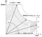
- FIG. 2 is a schematic diagram showing the relationship between speed (position) and force in the input to the actuator.
- control energy of velocity (position) and control energy of force based on the combined impedance with the contact object are distributed, and further, the second conversion is performed.
- the conversion is performed to determine the input to the actuator.
- Curves C1 to C3 in FIG. 2 represent functions in which the control energy is maintained before and after the second conversion when a specific control energy is set. That is, when the distribution of the control energy represented by a point on any of the curves C1 to C3 is performed, when one of the velocity (position) and the force is increased, the other is reduced, and the control energy is maintained as a whole. To be done.
- control energy distribution points can be set at points not limited to the same curve. That is, in the present invention, when at least one of velocity (position) or force is expanded or contracted by the second conversion, control is performed to a point existing on the curve in which the control energy is maintained in the expansion or contraction direction of the control energy. It is possible to change the energy distribution point. In this case, when the power to be supplied to the control target system S is also changed, the power supply unit PS can supply the power corresponding to this change.
- the settable range of the distribution point of the control energy is restricted to the range below the force limit and the speed limit, as shown in FIG. That is, when the distribution point of the control energy calculated by the second conversion becomes a point exceeding the force limit or the speed limit, the point having the force limit or the speed limit as the upper limit is set as the control energy distribution point, and Input is determined.
- the condition (upper limit value) regarding the control energy of the velocity (position) and the control energy of the force is set from the viewpoint of the control energy.
- the power supply unit PS includes a power source such as a battery and a control function of the supplied power, and supplies the control target system S with the power corresponding to the input to the actuator determined by the integrated conversion block IFT.
- the power supply control function of the power supply unit PS maintains/increases/decreases the power supply to the control target system S according to the change in the control energy that the control target system S should output.
- the function-specific force/speed assignment conversion block FT when the position information in the actuator of the controlled system S is input to the function-specific force/speed assignment conversion block FT, the speed (position) and force information obtained based on the position information.
- the function-based force/velocity allocation conversion block FT the control rules for the position and force regions corresponding to the functions are applied using. Then, the force according to the function is calculated in the ideal force source block FC, the speed (position) according to the function is calculated in the ideal velocity (position) source block PC, and the force and the speed (position) are calculated. Control energy is distributed to each.
- the calculation results in the ideal force source block FC and the ideal speed (position) source block PC become information indicating the control target of the control target system S, and these calculation results indicate the set speed (position) in the integrated conversion block IFT.
- the weight is changed according to the contribution ratio of the control energy and the control energy of the force, and then the weight is changed to the input value of the actuator and input to the control target system S.
- the actuator of the controlled system S basically expands the control amount of the set speed (position) and the control amount of the force while complying with the function defined by the function-specific force/speed assignment conversion block FT.
- the target operation of the robot is realized by executing the operation in which the reduction is reflected. That is, in the present invention, it is possible to more appropriately realize the function required for the robot.
- the control function of the power supply in the power supply unit PS can also expand or contract the overall control energy output by the actuator to realize expansion or contraction of the speed (position) and force.
- the velocity (position) and the force from the present position and the velocity (position) and the force as the reference values of the function are input, and the velocity (position) and the force are respectively inputted.
- Is applied in the acceleration dimension That is, the force in the actuator is represented by the product of mass and acceleration, and the velocity (position) in the actuator is represented by the integral of acceleration. Therefore, by controlling the speed (position) and the force via the acceleration region, it is possible to acquire the current position of the actuator and realize the intended function.
- the force control energy based on the value of the force region calculated by the ideal force source block FC and the ideal velocity (position) source block PC are used.
- the control energy of the velocity (position) based on the calculated value of the region of the velocity (position) is converted to change the contribution rate of each control energy. This makes it possible to increase the weight of force control and the weight of speed (position) control.
- the function-based force/velocity allocation conversion block FT coordinate conversion for speed (position) and force obtained based on the input current position of the actuator (conversion from real space to virtual space corresponding to the function to be realized) ) Is defined.
- the function-specific force/velocity allocation conversion block FT the velocity (position) and the force from the present position and the velocity (position) and the force as the reference values of the function are input, and the velocity (position) and the force are respectively inputted. Is applied in the acceleration dimension. That is, the force in the actuator is represented by the product of mass and acceleration, and the velocity (position) in the actuator is represented by the integral of acceleration. Therefore, by controlling the speed (position) and the force via the acceleration region, it is possible to acquire the current position of the actuator and realize the intended function.
- FIG. 3 is a block diagram showing a functional configuration of the position/force control system 1 in which a force/tactile transmission function is defined in the function-specific force/speed assignment conversion block FT.
- FIG. 4 is a schematic diagram showing the concept of the master/slave system that realizes the force/tactile transmission function.
- the position/force control system 1 shown in FIG. 3 includes a master side position/force control device and a slave side control device including a master device and a slave device as a controlled system S controlled by the control law shown in FIG. It is composed of a position/force control device.
- the position/force control system 1 includes, for example, a master device and a slave device having an actuator by an information processing device including a PC (Personal Computer), a memory, a ROM (Read Only Memory), a processor, and a storage device (hard disk, etc.). It can be realized as a control system.
- PC Personal Computer
- ROM Read Only Memory
- processor processor
- storage device hard disk, etc.
- the operation of the master device is transmitted to the slave device, and the reaction force input from the object to the slave device is fed back to the master device.
- Function bilateral control function
- the coordinate conversion in the function-specific force/speed assignment conversion block FT is expressed by the following equations (4) and (5).
- x′ p is a velocity for deriving the state value of velocity (position)
- x′ f is a velocity related to the state value of force
- x′ m is the speed of the reference value (input from the master device) (differential value of the current position of the master device)
- x′ s is the current speed of the slave device (differential value of the current position).
- f p is a force related to the state value of speed (position)
- f f is a force for deriving the state value of force.
- f m is the force of the reference value (input from the master device)
- f s is the current force of the slave device.
- the integrated conversion block IFT can be set to a conversion content different from the simple inverse conversion of the conversion in the function-based force/speed allocation conversion block FT, and the control energy Specific conversion contents are set from the viewpoint of the contribution rate.
- FIG. 5 is a schematic diagram showing the concept of an application example when the second conversion in the integrated conversion block IFT is the reverse conversion of the first conversion and when it is other than the reverse conversion of the first conversion.
- FIG. 5 shows an example in which the contribution rates of the force control energy and the velocity (position) control energy are maintained and changed in the configuration examples shown in FIGS. 3 and 4.
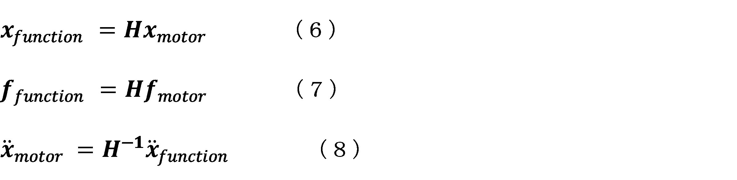
- coordinate transformations corresponding to equations (1) and (2) are represented by equations (6) and (7)
- coordinate transformation corresponding to equation (3) is represented by equation (8). To do.
- H is a first conversion matrix
- x motor is a vector whose elements are the velocity (position) based on the action of the reference value and the actuator
- x function is the first conversion matrix and the vector x motor is It is a vector whose elements are the velocity (position) in the converted virtual space.
- f motor is a vector whose elements are the velocity (position) based on the action of the reference value and the actuator
- f function is the force in the virtual space in which the vector f motor is transformed by the first transformation matrix. Is a vector whose elements are.
- H ⁇ 1 is the inverse transformation of the first transformation matrix
- x′′ motor is a vector whose elements are accelerations (variables in real space) that define the input to each actuator
- x′ The “ function” is a vector whose elements are accelerations (variables in the virtual space) defined by the control energy of the velocity (position) calculated in the virtual space and the control energy of the force.
- ⁇ is a transformation matrix different from the inverse transformation matrix of the first transformation matrix H.
- the condition set for the control energy is satisfied by applying the second conversion to the allocation result of the control energy by the first conversion, and , Processing corresponding to expansion or contraction of at least one of velocity or position energy and force energy is performed. Therefore, it is possible to supply the necessary electric power to the system to be controlled while flexibly managing the control energy to the target state. Therefore, it is possible to provide a technique for more appropriately realizing the function required for the robot.
- the variable in the real space is converted into the variable in the virtual space by the first conversion matrix representing the function, and the control energy of the velocity (position) and the control energy of the force are converted to the control energy in the virtual space.
- the value of the region of velocity (position) and force represented by the virtual space is converted into the value of the region of input to the controlled system S by the second conversion matrix.
- the second conversion at least one of the velocity (position) and the force can be expanded or reduced while satisfying the conditions regarding the control energy of the velocity (position) and the control energy of the force.
- the target value relating to the force in the ideal force source block FC and the target value relating to the velocity (position) in the ideal velocity (position) source block PC are expanded by at least one of the force control energy and the velocity (position) control energy. It is also possible to realize expansion or contraction of either speed (position) or force by setting the value to be contracted.
- the second conversion matrix can be the inverse conversion matrix of the first conversion matrix.
- the ideal force source block FC when a function similar to the function indicated by the reference value is realized, zero is set as the target value, but when scaling is performed, a function to reproduce is shown. It is possible to set a value by enlarging or reducing the information. That is, when the control energy of the force is multiplied by Gf with respect to the function indicated by the reference value, the target value is set to be Gf times when the calculation result by the ideal force source block FC follows the reference value. You can
- the ideal speed (position) source block PC when a function similar to the function indicated by the reference value is realized, zero is set as the target value, but when scaling is performed, the function to reproduce is set.
- a value obtained by enlarging or reducing the information shown can be set. That is, when the control energy of the speed (position) is multiplied by Gp with respect to the function indicated by the reference value, the calculation result by the ideal speed (position) source block PC is set to Gp times when the reference value is followed.
- a target value can be set.
- the settable range of the distribution point of the control energy is limited to the range below the force limit and the speed limit shown in FIG. Therefore, the upper limit value corresponding to the force limit is set for the calculation result of the ideal force source block FC, and the upper limit value corresponding to the speed limit is set for the calculation result of the ideal velocity (position) source block PC. Is set.
- FIG. 6 shows an application example in which the calculation result in the ideal force source block FC and the calculation result in the ideal velocity (position) source block PC are set as target values that follow the reference value, and when the target values are set to follow the reference value. It is a schematic diagram which shows the concept of.
- FIG. 6 shows an example in which the contribution rates of the force control energy and the velocity (position) control energy are maintained and changed in the configuration examples shown in FIGS. 3 and 4.
- the target value relating to the force in the ideal force source block FC and the target value relating to the velocity (position) in the ideal velocity (position) source block PC are represented by the control energy of the force and the control energy of the velocity (position).
- the control energy is enlarged or reduced from the energy E1 to the energy E2 in the calculation result of the ideal force source block FC and the calculation result of the ideal velocity (position) source block PC.
- the control parameters acquired by the bilateral control by the coordinate conversion of the equations (6) to (8) are recorded in the same manner as the control by the coordinate conversion of the equation (9).
- An operation different from the operation of the slave at the time of recording for example, different mechanical impedance to perform soft control
- the power required for operation will be different than the power supplied to the slaves in bilateral control.
- the overall control energy can be expanded or reduced at the stage of input to the controlled system S (that is, input to the actuator). That is, as shown in the above-described embodiment, at least one of the speed (position) and the force can be expanded or reduced by the second conversion in the integrated conversion block IFT, and the power supplied by the power supply unit PS can be reduced.
- the control function allows the operation of the actuator to be scaled up or down. In this case, the overall control energy is expanded or reduced while the contribution ratios of the control energy of the velocity (position) and the control energy of the force calculated by the second conversion are maintained.
- the settable range of the distribution point of the control energy is limited to the range below the force limit and the speed limit shown in FIG. Therefore, in the input to the actuator, the upper limit value is set so that the behavior of the actuator becomes equal to or less than the force limit and the velocity limit.
- the output of the actuator is changed in the processing other than the first coordinate conversion and the second coordinate conversion. Therefore, the current position of the actuator used as the input in the first coordinate conversion may be corrected (that is, the control energy is restored to a state in which the control energy is not enlarged or reduced) according to the degree of enlargement or reduction.
- control energy is set at the stage of determining the input to the actuator after converting the allocation result of the control energy by the first conversion into the variable in the real space by the second conversion.
- the above conditions are satisfied, and a process corresponding to expansion or contraction of at least one of energy of velocity or position and energy of force is performed.
- control law of this modification it is possible to supply the necessary power to the system to be controlled while flexibly managing the control energy to the target state.
- the function-specific force/speed assignment conversion means includes the speed (position) and force corresponding to the position-related information based on the action of the actuator.
- the first conversion is performed, in which the control energy is assigned to at least one of the velocity or position energy and the force energy in accordance with the function to be realized, based on the information of 1) and the information serving as the control reference.
- the control amount calculation means based on at least one of the speed or position energy and the force energy allocated by the function-based force/speed allocation conversion means, based on at least one of the speed or position control amount and the force control amount. And at least one of them is calculated.
- the integrating means integrates the controlled variable of the speed or position and the controlled variable of the force, and performs a second conversion into the controlled variable of the speed or position and the controlled variable of the force to return the output thereof to the actuator.
- the condition set for the control energy is satisfied, and at least one of the velocity or position energy and the force energy is satisfied. Processing corresponding to enlargement or reduction is performed.
- the condition set for the control energy is satisfied, and at least one of the velocity or position energy and the force energy is expanded or A process corresponding to the reduction is performed. Therefore, it is possible to supply the necessary electric power to the system to be controlled while flexibly managing the control energy to the target state. Therefore, it is possible to provide a technique for more appropriately realizing the function required for the robot.
- the present invention is not limited to the above-described embodiment, and modifications, improvements, etc. within the scope of achieving the object of the present invention are included in the present invention.
- the position/force control device is a combination of two or more configurations of the above-described embodiments and modified examples 1 and 2.
- the control rules of the present invention one of the position or velocity control and the force control can be used.
- the processing in the above-described embodiments and the like can be executed by either hardware or software. That is, it is sufficient that the position/force control system 1 is provided with a function capable of executing the above-described processing, and what kind of functional configuration and hardware configuration are implemented to implement this function is not limited to the above-mentioned example. ..
- a program constituting the software is installed in a computer from a network or a storage medium.
- the storage medium that stores the program is composed of a removable medium that is distributed separately from the device body, or a storage medium that is installed in advance in the device body.
- the removable medium includes, for example, a semiconductor memory (flash memory or the like), a magnetic disk, an optical disk, a magneto-optical disk, or the like.
- the optical disc is composed of, for example, a CD-ROM (Compact Disc-Read Only Memory), a DVD (Digital Versatile Disc), and a Blu-ray Disc (registered trademark).
- the magneto-optical disk is composed of MD (Mini-Disc) or the like.
- the storage medium incorporated in the main body of the apparatus in advance is composed of, for example, a ROM or a hard disk in which a program is stored.
Landscapes
- Engineering & Computer Science (AREA)
- Robotics (AREA)
- Mechanical Engineering (AREA)
- Automation & Control Theory (AREA)
- Physics & Mathematics (AREA)
- General Physics & Mathematics (AREA)
- Human Computer Interaction (AREA)
- Manufacturing & Machinery (AREA)
- Manipulator (AREA)
- Control Of Position Or Direction (AREA)
- Feedback Control In General (AREA)
Abstract
Description
ところが、従来のロボットの動作は、環境適応性や柔軟性に欠けており、人間の身体的行為を適切に実現するには至っていない。
ここで、マスタ・スレーブシステムにより取得した時系列な位置情報及び力情報を用いてアクチュエータの運動を人工再現する取り組みも行われているが、再現時における機械的インピーダンスが常に一定であり、依然として環境の位置・大きさ・機械的インピーダンスといった環境変動への適応性に欠けている。
なお、マスタ・スレーブシステムによって遠隔制御を行うロボットに関する技術は、例えば特許文献1及び特許文献2に記載されている。
また、今後のロボットには、人間の身体的行為を単純に実現することに加え、人間の能力を拡張した機能や人間には備えられていない機能等を実現することも求められる。
即ち、従来の技術においては、ロボットに求められる機能を適切に実現する上で、改善の余地がある。
本発明の課題は、ロボットに求められる機能をより適切に実現するための技術を提供することである。
アクチュエータの作用に基づく位置に関する情報に対応する速度(位置)及び力の情報と、制御の基準となる情報とに基づいて、実現される機能に応じて、制御エネルギーを速度または位置のエネルギーと力のエネルギーとのうち、少なくとも一方に割り当てる第1の変換を行う機能別力・速度割当変換手段と、
前記機能別力・速度割当変換手段によって割り当てられた速度または位置のエネルギーと力のエネルギーとのうち、少なくとも一方に基づいて、速度または位置の制御量と力の制御量との少なくとも一方を算出する制御量算出手段と、
前記速度または位置の制御量と前記力の制御量とを統合し、その出力をアクチュエータに戻すべく前記速度または位置の制御量と前記力の制御量とに第2の変換を行って、前記アクチュエータへの入力を決定する統合手段と、
を備え、
前記第1の変換による前記制御エネルギーの割り当て結果から前記アクチュエータへの入力を決定する処理において、前記制御エネルギーについて設定された条件を充足し、かつ、前記速度または位置のエネルギーと力のエネルギーとの少なくとも一方の拡大または縮小に相当する処理を含むことを特徴とする。
初めに、本発明に係る位置・力制御装置、位置・力制御方法及びプログラムに適用される基本的原理について説明する。
したがって、以下、本実施形態において、「行為」とは、人間の身体における部位の個別の「機能」を構成要素として実現される統合的な機能を表すものとする。例えば、中指の曲げ伸ばしを伴う行為(ねじを回す行為等)は、中指の各関節の機能を構成要素とする統合的な機能である。
本発明における基本的原理は、どのような行為も力源と速度(位置)源及び行為を表す変換の三要素で数理的に表現できることから、変換及び逆変換により定義される変数群に対し、双対関係にある理想力源及び理想速度(位置)源より制御エネルギーを制御対象のシステムに供給することで、抽出した身体的行為を構造化し、再構築あるいは拡張増幅し身体的行為を可逆的に自動実現(再現)する、というものである。
また、行為を表す変換に対して、単純な逆変換を行った場合、行為を再現可能であるが、本発明においては、行為を表す変換の逆変換とは異なる変換を行うことにより、制御エネルギーを目的とする状態に柔軟に管理しつつ、制御対象のシステムに必要な電力を供給することを可能としている。
図1に示す基本的原理は、人間の身体的行為を実現するために利用可能なアクチュエータの制御則を表しており、アクチュエータの現在位置を入力として、位置(または速度)あるいは力の少なくとも一方の領域における演算を行うことにより、アクチュエータの動作を決定するものである。
即ち、本発明の基本的原理は、制御対象システムSと、機能別力・速度割当変換ブロックFTと、理想力源ブロックFCあるいは理想速度(位置)源ブロックPCの少なくとも一つと、統合変換ブロックIFTと、電力供給部PSとを含む制御則として表される。

機能別力・速度割当変換ブロックFTにおける座標変換を、実現する機能に応じて設定することにより、各種行為を実現したり、スケーリングを伴う行為の再現を行ったりすることができる。
即ち、本発明の基本的原理では、機能別力・速度割当変換ブロックFTにおいて、アクチュエータ単体の変数(実空間上の変数)を、実現する機能を表現するシステム全体の変数群(仮想空間上の変数)に“変換”し、速度(位置)の制御エネルギーと力の制御エネルギーとに制御エネルギーを割り当てる。そのため、アクチュエータ単体の変数(実空間上の変数)のまま制御を行う場合と比較して、速度(位置)の制御エネルギーと力の制御エネルギーとを独立に与えることが可能となっている。

統合変換ブロックIFTは、式(3)によって算出された加速度の値から、各アクチュエータに入力される値(電流値等)を算出する。
図2に示すように、本発明における基本原理では、第1の変換によって、接触物体との合成インピーダンスに基づく速度(位置)の制御エネルギー及び力の制御エネルギーの分配が行われ、さらに第2の変換が行われることにより、アクチュエータへの入力が決定される。
図2における曲線C1~C3は、特定の制御エネルギーを設定した場合に、第2の変換の前後において、制御エネルギーが維持される関数を示している。即ち、いずれかの曲線C1~C3上の点で表される制御エネルギーの分配が行われる場合、速度(位置)または力の一方が拡大されると、他方は縮小され、全体として制御エネルギーが維持される。
この場合、制御対象システムSに供給すべき電力にも変更が生じるところ、電力供給部PSは、この変更に対応する電力を供給することが可能となっている。
その結果、制御対象システムSのアクチュエータは、機能別力・速度割当変換ブロックFTによって定義された機能に従うことを基本としつつ、設定された速度(位置)の制御量及び力の制御量の拡大または縮小が反映された動作を実行し、目的とするロボットの動作が実現される。
即ち、本発明においては、ロボットに求められる機能をより適切に実現することが可能となる。
また、電力供給部PSにおける供給電力の制御機能によっても、アクチュエータが出力する全体の制御エネルギーを拡大または縮小し、速度(位置)及び力の拡大または縮小を実現することができる。
次に、本発明の基本的原理を適用した具体的なシステム構成例について説明する。
機能別力・速度割当変換ブロックFTでは、入力されたアクチュエータの現在位置に基づいて得られる速度(位置)及び力を対象とした座標変換(実現する機能に対応した実空間から仮想空間への変換(第1の変換))が定義されている。
即ち、アクチュエータにおける力は質量と加速度との積で表され、アクチュエータにおける速度(位置)は加速度の積分によって表される。そのため、加速度の領域を介して、速度(位置)及び力を制御することで、アクチュエータの現在位置を取得して、目的とする機能を実現することができる。
機能別力・速度割当変換ブロックFTでは、このような現在位置から速度(位置)及び力と、機能の基準値としての速度(位置)及び力とを入力として、速度(位置)及び力それぞれについての制御則が加速度次元において適用される。
即ち、アクチュエータにおける力は質量と加速度との積で表され、アクチュエータにおける速度(位置)は加速度の積分によって表される。そのため、加速度の領域を介して、速度(位置)及び力を制御することで、アクチュエータの現在位置を取得して、目的とする機能を実現することができる。
この場合、機能別力・速度割当変換ブロックFTにおける座標変換は、次式(4)及び(5)として表される。

図5は、統合変換ブロックIFTにおける第2の変換を第1の変換の逆変換とする場合及び第1の変換の逆変換以外とする場合の適用例の概念を示す模式図である。
図5では、図3及び図4に示す構成例において、力の制御エネルギー及び速度(位置)の制御エネルギーの寄与率を維持する場合及び変更する場合の例が示されている。
なお、以下の説明において、式(1)及び(2)に対応する座標変換を式(6)及び(7)で表し、式(3)に対応する座標変換を式(8)で表すものとする。
このとき、第1の変換の前後及び第2の変換の前後において、制御エネルギーはエネルギーE1に維持される。
これに対し、図5において、式(9)のような第2の変換を行った場合、第2の変換の前後において、制御エネルギーはエネルギーE1からエネルギーE2に拡大または縮小される。

このような変換が行われた場合、式(6)~(8)の座標変換によるバイラテラル制御で取得された制御パラメータを記録しておき、記録時のスレーブの動作とは異なる動作(例えば、機械インピーダンスを異ならせて柔らかい制御を行う等)を実現することができる。
なお、式(9)の変換を行う場合、第2の変換の前後において、制御エネルギーが式(6)~(8)の座標変換によるバイラテラル制御の場合とは異なることから、動作に必要な電力が、バイラテラル制御におけるスレーブに供給された電力とは異なるものとなる。
そのため、制御エネルギーを目的とする状態に柔軟に管理しつつ、制御対象のシステムに必要な電力を供給することができる。
したがって、ロボットに求められる機能をより適切に実現するための技術を提供することができる。
上述の実施形態において、機能を表す第1の変換行列によって実空間上の変数を仮想空間上の変数に変換し、仮想空間において速度(位置)の制御エネルギーと力の制御エネルギーとに制御エネルギーを割り当てた後、第2の変換行列によって、仮想空間が表す速度(位置)及び力の領域の値から制御対象システムSへの入力の領域の値に変換するものとした。そして、第2の変換において、速度(位置)の制御エネルギー及び力の制御エネルギーに関する条件を充足しつつ、速度(位置)または力の少なくとも一方の拡大または縮小を可能とした。
具体的には、理想力源ブロックFCにおいて、基準値が示す機能と同様の機能を実現する場合には、目標値としてゼロが設定されるところ、スケーリングを行う場合には、再現する機能を示す情報を拡大・縮小した値を設定することができる。即ち、基準値が示す機能に対し、力の制御エネルギーをGf倍する場合には、理想力源ブロックFCによる演算結果を基準値に追従する場合のGf倍とするように目標値を設定することができる。
ただし、この場合にも、制御エネルギーの分配点の設定可能範囲は、図2に示す力限界及び速度限界以下の範囲に制約される。そのため、理想力源ブロックFCの演算結果に対して、力限界に対応する上限値が設定されると共に、理想速度(位置)源ブロックPCの演算結果に対して、速度限界に対応する上限値が設定される。
図6では、図3及び図4に示す構成例において、力の制御エネルギー及び速度(位置)の制御エネルギーの寄与率を維持する場合及び変更する場合の例が示されている。
このとき、第1の変換の前後及び第2の変換の前後において、制御エネルギーはエネルギーE1に維持される。
なお、図6の記録時の例として示す制御を行う場合、第1の変換から第2の変換に至る過程(即ち、仮想空間における処理過程)において、制御エネルギーが拡大または縮小されることから、動作に必要な電力が、バイラテラル制御におけるスレーブに供給された電力とは異なるものとなる。
本変形例の制御則によっても、制御エネルギーを目的とする状態に柔軟に管理しつつ、制御対象のシステムに必要な電力を供給することができる。
上述の実施形態において、制御対象システムSへの入力(即ち、アクチュエータへの入力)の段階で、全体の制御エネルギーを拡大または縮小することができる。
即ち、上述の実施形態に示すように、統合変換ブロックIFTにおける第2の変換によって速度(位置)または力の少なくとも一方を拡大または縮小することが可能である他、電力供給部PSにおける供給電力の制御機能によって、アクチュエータの動作の規模を拡大または縮小することが可能である。この場合、第2の変換によって算出された速度(位置)の制御エネルギー及び力の制御エネルギーの寄与率は維持されたまま、全体の制御エネルギーが拡大または縮小される。
本変形例の制御則によって全体の制御エネルギーを拡大または縮小した場合、アクチュエータの出力が第1の座標変換及び第2の座標変換以外の処理において変更される。そのため、第1の座標変換における入力として用いられるアクチュエータの現在位置を、拡大または縮小した度合いに応じて補正(即ち、制御エネルギーが拡大または縮小されない状態に復元)することとしてもよい。
本変形例の制御則によっても、制御エネルギーを目的とする状態に柔軟に管理しつつ、制御対象のシステムに必要な電力を供給することができる。
以上のように、本発明の第1の態様に係る位置・力制御装置によれば、機能別力・速度割当変換手段は、アクチュエータの作用に基づく位置に関する情報に対応する速度(位置)及び力の情報と、制御の基準となる情報とに基づいて、実現される機能に応じて、制御エネルギーを速度または位置のエネルギーと力のエネルギーとのうち、少なくとも一方に割り当てる第1の変換を行う。そして、制御量算出手段は、機能別力・速度割当変換手段によって割り当てられた速度または位置のエネルギーと力のエネルギーとのうち、少なくとも一方に基づいて、速度または位置の制御量と力の制御量との少なくとも一方を算出する。さらに、統合手段は、速度または位置の制御量と前記力の制御量とを統合し、その出力をアクチュエータに戻すべく前記速度または位置の制御量と前記力の制御量とに第2の変換を行って、前記アクチュエータへの入力を決定する。そして、第1の変換による制御エネルギーの割り当て結果からアクチュエータへの入力を決定する処理において、制御エネルギーについて設定された条件を充足し、かつ、速度または位置のエネルギーと力のエネルギーとの少なくとも一方の拡大または縮小に相当する処理が行われる。
第1の変換による制御エネルギーの割り当て結果に第2の変換を適用することにより、制御エネルギーについて設定された条件を充足し、かつ、速度または位置のエネルギーと力のエネルギーとの少なくとも一方の拡大または縮小に相当する処理が行われる。
そのため、制御エネルギーを目的とする状態に柔軟に管理しつつ、制御対象のシステムに必要な電力を供給することができる。
したがって、ロボットに求められる機能をより適切に実現するための技術を提供することができる。
例えば、上述の実施形態及び変形例を適宜組み合わせることが可能であり、この場合、上述の実施形態及び変形例1,2のうち、2つ以上の構成を組み合わせた位置・力制御装置とすることができる。
また、上述の実施形態及び変形例1,2において、速度または位置の制御エネルギーあるいは力のエネルギーを縮小する場合、エネルギーをゼロとする(即ち、速度または位置の制御量あるいは力の制御量を無効とする)こととしてもよい。この場合、本発明の制御則のうち、位置または速度の制御と力の制御とのうち、一方を利用することができる。
即ち、上述の処理を実行できる機能が位置・力制御システム1に備えられていればよく、この機能を実現するためにどのような機能構成及びハードウェア構成とするかは上述の例に限定されない。
上述の処理をソフトウェアにより実行させる場合には、そのソフトウェアを構成するプログラムが、コンピュータにネットワークや記憶媒体からインストールされる。
Claims (8)
- アクチュエータの作用に基づく位置に関する情報に対応する速度(位置)及び力の情報と、制御の基準となる情報とに基づいて、実現される機能に応じて、制御エネルギーを速度または位置のエネルギーと力のエネルギーとのうち、少なくとも一方に割り当てる第1の変換を行う機能別力・速度割当変換手段と、
前記機能別力・速度割当変換手段によって割り当てられた速度または位置のエネルギーと力のエネルギーとのうち、少なくとも一方に基づいて、速度または位置の制御量と力の制御量との少なくとも一方を算出する制御量算出手段と、
前記速度または位置の制御量と前記力の制御量とを統合し、その出力をアクチュエータに戻すべく前記速度または位置の制御量と前記力の制御量とに第2の変換を行って、前記アクチュエータへの入力を決定する統合手段と、
を備え、
前記第1の変換による前記制御エネルギーの割り当て結果から前記アクチュエータへの入力を決定する処理において、前記制御エネルギーについて設定された条件を充足し、かつ、前記速度または位置のエネルギーと力のエネルギーとの少なくとも一方の拡大または縮小に相当する処理を含むことを特徴とする位置・力制御装置。 - 前記速度または位置のエネルギーと力のエネルギーとの少なくとも一方の拡大または縮小に相当する処理は、制御対象に対して予め設定された速度限界及び力限界の範囲で、前記速度または位置のエネルギーと力のエネルギーとの少なくとも一方を変化させることを特徴とする請求項1に記載の位置・力制御装置。
- 前記第2の変換は、前記第1の変換の逆変換とは異なる変換であり、前記速度または位置の制御量と前記力の制御量との少なくとも一方を拡大または縮小することを特徴とする請求項1または2に記載の位置・力制御装置。
- 前記第2の変換は、前記第1の変換の逆変換であり、前記統合手段の出力において全体のエネルギーを拡大または縮小することを特徴とする請求項1から3のいずれか1項に記載の位置・力制御装置。
- 前記アクチュエータとは異なる他のアクチュエータをさらに備え、
前記アクチュエータはマスタ装置及びスレーブ装置の一方として動作し、前記他のアクチュエータは前記マスタ装置及び前記スレーブ装置の他方として動作することを特徴とする請求項1から4のいずれか1項に記載の位置・力制御装置。 - マスタ装置として動作するアクチュエータ及びスレーブ装置として動作するアクチュエータの間で実行されるバイラテラル制御で取得されたパラメータに基づいて、前記速度または位置のエネルギーと力のエネルギーとを前記マスタ装置または前記スレーブ装置とは異ならせて前記アクチュエータを制御することを特徴とする請求項1から5のいずれか1項に記載の位置・力制御装置。
- アクチュエータの作用に基づく位置に関する情報に対応する速度(位置)及び力の情報と、制御の基準となる情報とに基づいて、実現される機能に応じて、制御エネルギーを速度または位置のエネルギーと力のエネルギーとのうち、少なくとも一方に割り当てる第1の変換を行う機能別力・速度割当変換ステップと、
前記機能別力・速度割当変換ステップにおいて割り当てられた速度または位置のエネルギーと力のエネルギーとのうち、少なくとも一方に基づいて、速度または位置の制御量と力の制御量との少なくとも一方を算出する制御量算出ステップと、
前記速度または位置の制御量と前記力の制御量とを統合し、その出力をアクチュエータに戻すべく前記速度または位置の制御量と前記力の制御量とに第2の変換を行って、前記アクチュエータへの入力を決定する統合ステップと、
を含み、
前記第1の変換による前記制御エネルギーの割り当て結果から前記アクチュエータへの入力を決定する処理において、前記制御エネルギーについて設定された条件を充足し、かつ、前記速度または位置のエネルギーと力のエネルギーとの少なくとも一方の拡大または縮小に相当する処理を含むことを特徴とする位置・力制御方法。 - コンピュータに、
アクチュエータの作用に基づく位置に関する情報に対応する速度(位置)及び力の情報と、制御の基準となる情報とに基づいて、実現される機能に応じて、制御エネルギーを速度または位置のエネルギーと力のエネルギーとのうち、少なくとも一方に割り当てる第1の変換を行う機能別力・速度割当変換機能と、
前記機能別力・速度割当変換機能によって割り当てられた速度または位置のエネルギーと力のエネルギーとのうち、少なくとも一方に基づいて、速度または位置の制御量と力の制御量との少なくとも一方を算出する制御量算出機能と、
前記速度または位置の制御量と前記力の制御量とを統合し、その出力をアクチュエータに戻すべく前記速度または位置の制御量と前記力の制御量とに第2の変換を行って、前記アクチュエータへの入力を決定する統合機能と、
を実現させ、
前記第1の変換による前記制御エネルギーの割り当て結果から前記アクチュエータへの入力を決定する処理において、前記制御エネルギーについて設定された条件を充足し、かつ、前記速度または位置のエネルギーと力のエネルギーとの少なくとも一方の拡大または縮小に相当する処理を含むことを特徴とするプログラム。
Priority Applications (2)
| Application Number | Priority Date | Filing Date | Title |
|---|---|---|---|
| JP2020571308A JP7553899B2 (ja) | 2019-02-07 | 2020-02-07 | 位置・力制御装置、位置・力制御方法及びプログラム |
| US17/429,240 US12285862B2 (en) | 2019-02-07 | 2020-02-07 | Position/force controller, and position/force control method and storage medium |
Applications Claiming Priority (2)
| Application Number | Priority Date | Filing Date | Title |
|---|---|---|---|
| JP2019-021104 | 2019-02-07 | ||
| JP2019021104 | 2019-02-07 |
Publications (1)
| Publication Number | Publication Date |
|---|---|
| WO2020162619A1 true WO2020162619A1 (ja) | 2020-08-13 |
Family
ID=71948290
Family Applications (1)
| Application Number | Title | Priority Date | Filing Date |
|---|---|---|---|
| PCT/JP2020/004933 Ceased WO2020162619A1 (ja) | 2019-02-07 | 2020-02-07 | 位置・力制御装置、位置・力制御方法及びプログラム |
Country Status (4)
| Country | Link |
|---|---|
| US (1) | US12285862B2 (ja) |
| JP (1) | JP7553899B2 (ja) |
| TW (1) | TW202045323A (ja) |
| WO (1) | WO2020162619A1 (ja) |
Families Citing this family (7)
| Publication number | Priority date | Publication date | Assignee | Title |
|---|---|---|---|---|
| US12562076B2 (en) | 2020-02-27 | 2026-02-24 | Keio University | Learning assistance system, learning assistance method, and learning assistance storage medium |
| US12111966B2 (en) | 2020-02-27 | 2024-10-08 | Keio University | Position/force control system, worn unit, control unit, position/force control method, and storage medium |
| JP7679178B2 (ja) | 2020-03-31 | 2025-05-19 | 地方独立行政法人神奈川県立産業技術総合研究所 | 医療用ドリル、及び医療用プログラム |
| WO2022230594A1 (ja) | 2021-04-26 | 2022-11-03 | 学校法人慶應義塾 | 機能管理システム、機能管理方法、及びプログラム |
| WO2022270319A1 (ja) | 2021-06-25 | 2022-12-29 | 慶應義塾 | 動作データ管理システム、動作データ管理方法、及びプログラム |
| US12397419B2 (en) * | 2023-03-06 | 2025-08-26 | Mitsubishi Electric Research Laboratories, Inc. | System and method for controlling a robotic manipulator |
| US20260078566A1 (en) * | 2024-02-02 | 2026-03-19 | Doosan Bobcat North America, Inc. | Force-based control of electrically actuated power machines |
Citations (3)
| Publication number | Priority date | Publication date | Assignee | Title |
|---|---|---|---|---|
| JP2007274783A (ja) * | 2006-03-30 | 2007-10-18 | Aisin Aw Co Ltd | 電動駆動制御装置及び電動駆動制御方法 |
| WO2013108356A1 (ja) * | 2012-01-16 | 2013-07-25 | 三菱電機株式会社 | モータ制御装置 |
| WO2015041046A1 (ja) * | 2013-09-19 | 2015-03-26 | 学校法人慶應義塾 | 位置・力制御装置、位置・力制御方法及びプログラム |
Family Cites Families (26)
| Publication number | Priority date | Publication date | Assignee | Title |
|---|---|---|---|---|
| JPH07295650A (ja) | 1994-04-21 | 1995-11-10 | Ricoh Co Ltd | 多関節型ロボットの制御方法 |
| WO1998026905A1 (fr) * | 1996-12-19 | 1998-06-25 | Honda Giken Kogyo Kabushiki Kaisha | Controleur d'attitude de robot mobile sur jambes |
| US7672741B2 (en) | 2003-07-24 | 2010-03-02 | Keio University | Position/force control device |
| US7731670B2 (en) * | 2007-02-02 | 2010-06-08 | Honda Motor Co., Ltd. | Controller for an assistive exoskeleton based on active impedance |
| US20090132088A1 (en) * | 2007-04-24 | 2009-05-21 | Tairob Ltd. | Transfer of knowledge from a human skilled worker to an expert machine - the learning process |
| JP2009279699A (ja) | 2008-05-21 | 2009-12-03 | Nagaoka Univ Of Technology | 位置・力再現方法および位置・力再現装置 |
| JP5242342B2 (ja) * | 2008-10-31 | 2013-07-24 | 株式会社東芝 | ロボット制御装置 |
| WO2011001569A1 (ja) * | 2009-07-02 | 2011-01-06 | パナソニック株式会社 | ロボット、ロボットアームの制御装置、及びロボットアームの制御プログラム |
| US8885315B2 (en) * | 2009-10-15 | 2014-11-11 | Hamilton Sundstrand Corporation | Multi-actuator motion control system |
| US8942908B2 (en) * | 2010-04-30 | 2015-01-27 | GM Global Technology Operations LLC | Primary torque actuator control systems and methods |
| JP5650814B1 (ja) | 2013-07-05 | 2015-01-07 | ファナック株式会社 | フィードフォワード制御を備えたモータ制御装置 |
| DE102013016019B3 (de) * | 2013-09-25 | 2015-03-19 | Festo Ag & Co. Kg | Verfahren zum Betreiben eines mehrgliedrigen Manipulators |
| JP6511715B2 (ja) * | 2013-10-31 | 2019-05-15 | セイコーエプソン株式会社 | ロボット制御装置、ロボットシステム、及びロボット |
| JP5893665B2 (ja) * | 2014-04-14 | 2016-03-23 | ファナック株式会社 | 作用された力に応じて移動されるロボットを制御するロボット制御装置 |
| EP4331522B1 (en) * | 2015-06-10 | 2025-09-03 | Intuitive Surgical Operations, Inc. | System for patient-side instrument control |
| JP6564739B2 (ja) * | 2016-06-30 | 2019-08-21 | 日立建機株式会社 | 作業機械 |
| JP6960242B2 (ja) * | 2017-05-19 | 2021-11-05 | 川崎重工業株式会社 | ロボットシステム及びロボットシステムの制御方法 |
| JP7018759B2 (ja) | 2017-12-14 | 2022-02-14 | 学校法人慶應義塾 | 位置・力制御装置 |
| JP6964293B2 (ja) | 2018-03-08 | 2021-11-10 | 地方独立行政法人神奈川県立産業技術総合研究所 | 力触覚伝達システム、力触覚伝達方法及びプログラム |
| US20190367029A1 (en) * | 2018-05-30 | 2019-12-05 | International Business Machines Corporation | Dynamic speed controller for vehicle |
| US20200323657A1 (en) * | 2019-04-15 | 2020-10-15 | Board Of Regents, The University Of Texas System | Systems And Methods For Robotic Mirror Therapy Of The Hand |
| CN121910476A (zh) * | 2019-09-24 | 2026-04-24 | 直观外科手术操作公司 | 用于控制器械握持行为的方法和系统 |
| CN111136633B (zh) * | 2020-01-13 | 2021-04-09 | 燕山大学 | 针对时变时延下柔性主-从机器人系统的全状态控制方法 |
| JP7679178B2 (ja) * | 2020-03-31 | 2025-05-19 | 地方独立行政法人神奈川県立産業技術総合研究所 | 医療用ドリル、及び医療用プログラム |
| WO2023058203A1 (ja) * | 2021-10-07 | 2023-04-13 | ファナック株式会社 | 制御装置、機械システム、及び表示装置 |
| JP2023069957A (ja) * | 2021-11-08 | 2023-05-18 | トヨタ紡織株式会社 | 位置・力制御システム、位置・力制御装置、位置・力制御方法及びプログラム |
-
2020
- 2020-02-07 TW TW109103801A patent/TW202045323A/zh unknown
- 2020-02-07 WO PCT/JP2020/004933 patent/WO2020162619A1/ja not_active Ceased
- 2020-02-07 JP JP2020571308A patent/JP7553899B2/ja active Active
- 2020-02-07 US US17/429,240 patent/US12285862B2/en active Active
Patent Citations (3)
| Publication number | Priority date | Publication date | Assignee | Title |
|---|---|---|---|---|
| JP2007274783A (ja) * | 2006-03-30 | 2007-10-18 | Aisin Aw Co Ltd | 電動駆動制御装置及び電動駆動制御方法 |
| WO2013108356A1 (ja) * | 2012-01-16 | 2013-07-25 | 三菱電機株式会社 | モータ制御装置 |
| WO2015041046A1 (ja) * | 2013-09-19 | 2015-03-26 | 学校法人慶應義塾 | 位置・力制御装置、位置・力制御方法及びプログラム |
Also Published As
| Publication number | Publication date |
|---|---|
| JP7553899B2 (ja) | 2024-09-19 |
| US12285862B2 (en) | 2025-04-29 |
| TW202045323A (zh) | 2020-12-16 |
| US20220134542A1 (en) | 2022-05-05 |
| JPWO2020162619A1 (ja) | 2020-08-13 |
Similar Documents
| Publication | Publication Date | Title |
|---|---|---|
| JP7553899B2 (ja) | 位置・力制御装置、位置・力制御方法及びプログラム | |
| Aifer et al. | From quantum speed limits to energy-efficient quantum gates | |
| PL359134A1 (en) | Control system for actuators in an aircraft | |
| CN104283484A (zh) | 具备前馈控制的电动机控制装置 | |
| WO2021025087A1 (ja) | 位置・力制御装置、位置・力制御方法及びプログラム | |
| CN110703609A (zh) | 一种电机伺服系统智能运动控制方法 | |
| US11400590B2 (en) | Optimal control of coupled admittance controllers | |
| WO2020137286A1 (ja) | 同期制御装置、同期制御システム、同期制御方法及びシミュレーション装置 | |
| US20240202569A1 (en) | Learning device, learning method, and recording medium | |
| Awan et al. | Model-mediated teleoperation for remote haptic texture sharing: Initial study of online texture modeling and rendering | |
| WO2024209686A1 (ja) | 加工シミュレーション装置及び加工シミュレーション方法 | |
| JP2018049583A (ja) | シミュレーション方法、コンピュータプログラム、及びシミュレーション装置 | |
| JP7730107B2 (ja) | 習得支援システム、習得支援方法、及び習得支援プログラム | |
| JP6933758B1 (ja) | 情報処理プログラム、情報処理装置及び情報処理方法 | |
| Perera et al. | Review on bilateral teleoperation with force, position, power and impedance scaling | |
| Gonenc et al. | Virtual tissue cutting with haptic feedback using a hybrid actuator with dc servomotor and magnetorheological brake | |
| JP7305061B2 (ja) | パラメータ調整装置およびパラメータ調整方法 | |
| Mishra et al. | A new class of generalized continuous robust control algorithm for arbitrary order systems | |
| Audette et al. | A PC-based system architecture for real-time finite element-based tool-specific surgical simulation | |
| WO2024189847A1 (ja) | 処理装置、処理方法、および記録媒体 | |
| KR102911221B1 (ko) | 강화 학습 기반의 가공 지도를 이용한 단조 공정의 제어변수를 최적화하기 위한 장치 및 이를 위한 방법 | |
| JP2948549B2 (ja) | 高次ダイナミクス型自動制御方法及び装置 | |
| US20230264342A1 (en) | Control system, control method, and storage medium | |
| Marković et al. | The Model in Coded Digital Design Process–Digital Chain Case | |
| Joli et al. | A new approach to solve constraint forces of virtual fixtures in haptic rendering |
Legal Events
| Date | Code | Title | Description |
|---|---|---|---|
| 121 | Ep: the epo has been informed by wipo that ep was designated in this application |
Ref document number: 20752485 Country of ref document: EP Kind code of ref document: A1 |
|
| ENP | Entry into the national phase |
Ref document number: 2020571308 Country of ref document: JP Kind code of ref document: A |
|
| NENP | Non-entry into the national phase |
Ref country code: DE |
|
| 122 | Ep: pct application non-entry in european phase |
Ref document number: 20752485 Country of ref document: EP Kind code of ref document: A1 |
|
| WWG | Wipo information: grant in national office |
Ref document number: 17429240 Country of ref document: US |