WO2020162603A1 - 異常検出装置、シミュレータ、プラント監視システム、異常検出方法及びプログラム - Google Patents
異常検出装置、シミュレータ、プラント監視システム、異常検出方法及びプログラム Download PDFInfo
- Publication number
- WO2020162603A1 WO2020162603A1 PCT/JP2020/004842 JP2020004842W WO2020162603A1 WO 2020162603 A1 WO2020162603 A1 WO 2020162603A1 JP 2020004842 W JP2020004842 W JP 2020004842W WO 2020162603 A1 WO2020162603 A1 WO 2020162603A1
- Authority
- WO
- WIPO (PCT)
- Prior art keywords
- abnormality
- actual machine
- time
- occurred
- simulator
- Prior art date
Links
Images


Classifications
-
- G—PHYSICS
- G05—CONTROLLING; REGULATING
- G05B—CONTROL OR REGULATING SYSTEMS IN GENERAL; FUNCTIONAL ELEMENTS OF SUCH SYSTEMS; MONITORING OR TESTING ARRANGEMENTS FOR SUCH SYSTEMS OR ELEMENTS
- G05B23/00—Testing or monitoring of control systems or parts thereof
- G05B23/02—Electric testing or monitoring
Definitions
- the present invention relates to an abnormality detection device, a simulator, a plant monitoring system, an abnormality detection method, and a program.
- the present application claims priority based on Japanese Patent Application No. 2019-020252 filed in Japan on February 7, 2019, the contents of which are incorporated herein by reference.
- Patent Document 1 a pipeline that determines an abnormal occurrence time estimation method based on the identification result of the abnormal event and estimates the occurrence time of the identified abnormal event based on the goodness of fit and the abnormal occurrence time estimation method.
- An abnormality detection device is disclosed.
- a simulator is known that faithfully simulates the operation of the actual plant equipment by computer calculation. It is desired to apply such a simulator to accurately and early detect an abnormality in an actual machine.
- the present invention provides an abnormality detection device, a simulator, a plant monitoring system, an abnormality detection method, and a program that can solve the above problems.
- the abnormality detection device acquires an actual machine measurement value from the actual machine of the plant, an acquisition unit that acquires a control command from the control device of the plant, and a simulator calculation indicating the state of the actual machine of the plant.
- a simulation unit that calculates a value based on the control command, and if the degree of deviation of the actual machine measurement value with respect to the calculated simulator calculation value exceeds a predetermined determination threshold value, it is determined that an abnormality has occurred in the actual machine.
- An abnormality determination unit a notification processing unit that notifies that an abnormality has occurred when it is determined that the abnormality has occurred, and a time until the determination is made when the abnormality has been determined.
- An estimation unit that estimates the time when the abnormality occurs based on the time series of the actual machine measurement value.
- the simulation unit traces the simulator calculation value back to the value of the simulator calculation value at the time when the abnormality occurs.
- the estimation unit further estimates the type of the abnormality based on the condition that the actual machine measurement value at the time when the abnormality is determined to have occurred in the actual machine is satisfied.
- the estimation unit further reflects the occurrence of the abnormality in the simulation unit, and a simulator calculation obtained from a simulated operation from the time when the abnormality occurs to the current time.
- the type and scale of the abnormality is estimated based on the time series of values.
- the estimation unit at least after the time when it is determined that the abnormality has occurred, a time series of the actual machine measurement value acquired by the time when a predetermined time has elapsed, and the The type and scale of the abnormality are estimated based on the time-series similarity of the simulator calculated values.
- the estimation unit estimates the time at which the abnormality has occurred, based on the time-series change rate of the actual machine measurement value.
- the simulator acquires an actual machine measurement value from the actual machine of the plant, an acquisition unit that acquires a control command from the control device of the plant, and a simulator calculation value indicating the state of the actual machine of the plant.
- a simulation unit that calculates based on the control command, and an abnormality determination unit that determines that an abnormality has occurred in the actual machine when the degree of deviation of the actual machine measurement value with respect to the simulator calculation value exceeds a predetermined determination threshold value.
- a notification processing unit that notifies the operator of the occurrence of the abnormality, and when it is determined that the abnormality has occurred, the actual machine measured value up to the time when the determination is made And an estimation unit that estimates the time when the abnormality occurs based on the time series of.
- a plant monitoring system includes the control device and the abnormality detection device described above.
- the abnormality detection method obtains an actual machine measurement value from the actual machine of the plant, a step of obtaining a control command from the control device of the plant, and a simulator calculation value indicating the state of the actual machine of the plant. And a step of calculating based on the control command, when the degree of deviation of the actual machine measured value with respect to the calculated simulator calculation value exceeds a predetermined determination threshold, a step of determining that an abnormality has occurred in the actual machine And, if it is determined that the abnormality has occurred, a step of notifying that an abnormality has occurred, and, if it is determined that the abnormality has occurred, of the actual machine measured value up to the time when the determination is made. Estimating a time at which the abnormality occurs based on a time series.
- a program the computer of the abnormality detection apparatus, to obtain the actual machine measurement value measured from the actual machine of the plant, to obtain a control command from the control device of the plant, and the plant
- abnormality detection device simulator, plant monitoring system, abnormality detection method, and program, it is possible to accurately and early detect an abnormality in the actual machine using the simulator of the actual machine in the plant.
- the plant monitoring system 1 is, for example, a system that monitors the operation of an actual PLR of a nuclear power plant.
- the plant monitoring system 1 includes a control device 10 and a simulator PLV.
- the control device 10 outputs a control command for controlling the operation of the actual plant PLR of the plant.
- the control device 10 also outputs the same signal as the control command output to the actual PLR to the simulator PLV.
- the control device 10 acquires a measurement value (hereinafter, also referred to as “actual machine measurement value”) from the actual machine PLR.
- the simulator PLV also acquires the actual machine measured value.
- the simulator PLV acquires a calculated value (hereinafter, also referred to as “simulator calculated value”) indicating the operating state of the actual PLR calculated by itself. That is, the simulator PLV acquires the actual machine measured value and the simulator calculated value from each of the actual machine PLR and the simulator PLV that have respectively operated based on the same control command.
- the simulator PLV also functions as an anomaly detection device that detects an anomaly in the actual machine PLR by comparing the acquired actual machine measured value and simulator calculated value.
- the actual PLR is equipment consisting of a turbine, a boiler, and various pipes.
- Various sensors are provided at various places of the actual machine PLR, and the control device 10 acquires actual machine measured values via these sensors.
- the various sensors include various instruments capable of measuring the temperature, pressure, flow rate, etc. of the pipe, a water storage amount detection sensor of the tank, a valve opening/closing detection sensor, and the like.
- the actual machine measurement values acquired through the plurality of sensors are sequentially acquired by the control device 10 and the simulator PLV.
- the simulator PLV is a so-called digital twin of an actual PLR, and is a computing device (computer) in substance. That is, the simulator PLV is an actual machine simulation model that simulates the operation of the actual machine PLR.
- the simulator PLV is constructed by a function group that represents a physical phenomenon that occurs in the actual PLL that is operating.
- the simulator PLV incorporates the control command received from the control device 10 to perform a physical calculation to simulate the operating state of the actual machine PLR.
- the simulator PLV is, for example, developed for the purpose of monitoring the actual machine PLR, driving training, etc., and is preferably constructed by a simulation model that has a proven record of consistency with the actual machine PLR.
- the actual PLR is assumed to be a device, equipment, etc. installed in a nuclear power plant in the present embodiment, but may be a power plant other than nuclear power (a thermal power plant, etc.) in other embodiments. It may be a device or equipment installed in a plant other than the power generation plant (for example, a chemical plant, a waste treatment plant, etc.).
- FIG. 2 is a diagram showing a functional configuration of the simulator according to the first embodiment.
- the simulator PLV includes a CPU 100, a memory 101, a communication interface 102, a monitor 103, an input device 104, and a storage 105.
- the memory 101 is a so-called main storage device, and instructions and data for the CPU 100 to operate based on a program are expanded.
- the communication interface 102 is an interface device for communicating with the outside of the simulator PLV (actual device PLR, control device 10, etc.).
- the monitor 103 is a display device that visually displays information, and may be, for example, a liquid crystal display or an organic EL display.
- the input device 104 is an input device that receives the operation of the user of the simulator PLV, and may be, for example, a general mouse, keyboard, touch sensor, or the like.
- the storage 105 is a so-called auxiliary storage device, and may be, for example, an HDD (Hard Disk Drive), an SSD (Solid State Drive), or the like.
- Anomaly estimation table DB (described later) is recorded in the storage 105.
- the CPU 100 is a processor that controls the overall operation of the simulator PLV. As shown in FIG. 2, the CPU 100 according to the present embodiment exerts functions as an acquisition unit 1000, an abnormality determination unit 1001, a notification processing unit 1002, an estimation unit 1003, and a simulation unit 1004. The functions of the CPU 100 will be described below.
- the acquisition unit 1000 acquires actual machine measurement values from various sensors provided in the actual machine PLR. Further, the acquisition unit 1000 acquires the simulator calculation value from the simulation unit 1004. Further, the acquisition unit 1000 acquires the control command output from the control device 10 to the actual PLR.
- the abnormality determination unit 1001 determines whether or not there is an abnormality in the operation of the actual PLR. Specifically, the abnormality determination unit 1001 determines that an abnormality has occurred in the actual PLR when the degree of deviation of the actual measurement value from the simulator calculation value acquired by the acquisition unit 1000 exceeds a predetermined determination threshold. ..
- the notification processing unit 1002 When the abnormality determination unit 1001 determines that an abnormality has occurred in the operation of the actual PLR, the notification processing unit 1002 notifies the operator via the monitor 103 or the like that an abnormality has occurred.
- the estimation unit 1003 estimates various information regarding the abnormality. Specifically, when it is determined that an abnormality has occurred in the operation of the actual PLR, the estimation unit 1003 estimates the time when the abnormality has occurred, the type of abnormality, and the scale of the abnormality. A specific mode of the process in which the estimation unit 1003 estimates the information regarding these abnormalities will be described later.
- the simulation unit 1004 reflects the actual machine measurement values and control commands acquired by the acquisition unit 1000 in a function group representing a physical phenomenon in the plant, performs a physical calculation, and calculates a simulator calculation value. For example, when a part of the control command output by the control device 10 is input, the function group outputs the same value as the actual machine measurement value measured by the actual machine PLR that has received the similar control command.
- the simulation unit 1004 acquires the latest control command through the acquisition unit 1000 and continuously calculates the simulator calculation value using the acquired control command.
- the simulation unit 1004 may use the actual machine measured value for calculating the simulator calculated value.
- the simulator PLV functions as a digital twin that simulates the operating state of the actual PLL in real time.
- the simulator calculated values include physical quantities such as the temperature and pressure of the monitoring target at the location where the actual sensor is not installed. By referring to the simulator calculated value, the operator can obtain various information that cannot be obtained only from the actual machine measured value, and can be useful for monitoring the plant. Therefore, when the simulator calculation value output by the simulation unit 1004 is used for monitoring the plant, the simulator calculation value is required to maintain high simulation accuracy.
- FIG. 3 is a diagram showing a processing flow of the simulator according to the first embodiment. Further, FIG. 4 to FIG. 8 are diagrams for explaining the processing of the simulator according to the first embodiment in detail.
- the processing flow shown in FIG. 3 is continuously and repeatedly executed while the actual PLR is operating.
- the simulator PLV acquisition unit 1000 acquires actual device measurement values through various sensors of the actual device PLR, and also acquires simulator calculation values from the simulation unit 1004 (step S30).
- the simulator calculation value is a physical quantity ⁇ calculated by the simulation unit 1004 using the control command and the like acquired by the acquisition unit 1000. This physical quantity ⁇ is also included in the actual machine measured value acquired by the acquisition unit 1000.
- the abnormality determination unit 1001 of the simulator PLV calculates the degree of deviation between the actual machine measured value acquired in step S30 and the simulator calculated value, and determines whether the degree of deviation exceeds a predetermined determination threshold value. Yes (step S31). For example, the abnormality determination unit 1001 compares the actual machine measured value of the physical quantity ⁇ with the simulator calculated value of the physical quantity ⁇ . When the degree of deviation does not exceed the predetermined determination threshold (step S31; NO), the abnormality determination unit 1001 determines that no abnormality has occurred in the actual PLR. In this case, the CPU 100 returns to the process of step S30.
- step S31 If the degree of deviation exceeds a predetermined determination threshold (step S31; YES), it is determined that an abnormality has occurred in the actual PLR. In this case, the notification processing unit 1002 of the simulator PLV notifies the operator of the occurrence of an abnormality through the monitor 103 or the like (step S32).
- FIG. 4 shows a time series DR of actual machine measurement values and a time series DV of simulator calculation values acquired from a certain reference time t0 to the current time (time ta).
- FIG. 4 shows a comparison between the actual machine measured value for one parameter (for example, the pressure of a certain pipe A) acquired from the actual machine PLR and the simulator calculated value for the same parameter (the pressure of the pipe A).
- the actual machine measured value and the simulator calculated value are actually compared for each of a plurality of types of parameters.
- the abnormality determination unit 1001 determines that an abnormality has occurred in the actual PLR.
- the notification processing unit 1002 notifies the occurrence of an abnormality at time ta (step S32). That is, at time ta, the occurrence of an abnormality is detected by the simulator PLV (abnormality detection device).
- the estimation unit 1003 of the simulator PLV executes the following processing in order to estimate various kinds of information regarding the abnormality that has occurred.
- the estimation unit 1003 estimates the time of occurrence of abnormality (step S33).
- the abnormality occurrence time is a time at which an abnormality actually occurs in the actual PLR, and is a time before the time at which the abnormality is detected (time ta shown in FIG. 4).
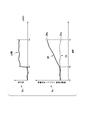
- step S33 The process of step S33 described above will be described in detail with reference to FIG. Similar to FIG. 4, the graph 5a shown in FIG. 5 shows the time series DR of the actual machine measured values and the time series DV of the simulator calculated values acquired from a certain reference time t0 to the current time (time ta). A graph 5b shown in FIG. 5 shows the change rate ⁇ DR which is the time derivative of the time series DR of the actual machine measured value.
- the estimation unit 1003 has an abnormality in the actual machine PLR based on the time series DR of the actual machine measurement values from the predetermined reference time t0 to the time (time ta) at which it is determined that there is an abnormality. Estimate the time. Specifically, the estimation unit 1003 calculates the change rate ⁇ DR of the time series DR of the actual machine measured values up to time ta, and further sets the time (time tb) when the change rate ⁇ DR exceeds a predetermined determination threshold ⁇ DRth. Identify.
- the time tb at which the rate of change ⁇ DR exceeds the determination threshold ⁇ DRth can be regarded as the change point of the time series DR trend of the actual machine measured value.
- the estimation unit 1003 estimates the time tb specified as described above as the time when the abnormality occurs.
- the estimation unit 1003 notifies the simulation unit 1004 of an accident signal indicating the occurrence of an abnormality.
- the simulation unit 1004 temporarily stops the calculation of the simulator calculation value.
- the estimation unit 1003 instructs the simulation unit 1004 to return the simulated state of the actual machine PLR to the operating state of the actual machine PLR at time tb.
- the simulation unit 1004 reproduces the simulator calculation value at time tb.
- the simulation unit 1004 records the simulator calculation value, actual machine measurement value, and control command for each time in the storage 105 in association with the time.
- the simulation unit 1004 When receiving an instruction from the estimation unit 1003 to return the simulated state to the time tb, the simulation unit 1004 reads the simulator calculation value and the like at the time tb from the storage 105 and reproduces the operating state of the actual PLR at the time tb.
- the estimation unit 1003 determines the type of abnormality that has occurred in the actual PLR (step S34).
- the type of abnormality is information that identifies the mode, nature, location of occurrence, etc. of the abnormality, and is, for example, information such as "pipe A break", “pipe B closed”, and "solenoid valve X failure".
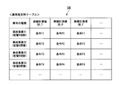
- the information table shown in FIG. 6 is an example of the abnormality estimation table DB stored in the storage 105 in advance.
- the abnormality estimation table DB a combination of conditions satisfied by a plurality of types of actual machine measurement values is recorded for each “abnormality type” defined in advance.
- the conditions T1, T2,..., P1, P2,..., F1, F2,... Shown in FIG. 6 are in the range of each actual machine measured value DR_T, DR_P, DR_F,. The following), or the range of the amount of change of each actual machine measured value DR_T, DR_P, DR_F,...
- the estimation unit 1003 refers to the abnormality estimation table DB and defines the time series DR of the actual machine measurement values acquired up to the current time (time ta) for each “abnormality type”. It is determined whether or not the combination of the above conditions is satisfied. For example, when the actual machine measured value DR_T satisfies the condition T1, the actual machine measured value DR_P satisfies the condition P1 and the actual machine measured value DR_F satisfies the condition F1, the estimation unit 1003 determines the accident event X1 in the actual machine PLR. It is estimated that (pipe A breakage) occurred.
- the estimation unit 1003 estimates that "one or both of the accident events Xa and Xb have occurred" in the actual PLR.
- step S35 the estimation unit 1003 performs the processing of steps S35 to S37 described below when estimating the scale of the abnormality that has occurred in the actual PLR.
- the process of step S35 will be described in detail with reference to FIG.
- the operation of the actual machine PLR simulated by the simulator PLV (simulation unit 1004) by physical calculation is calculated on the assumption that no abnormality occurs in the actual machine PLR. Therefore, when an abnormality occurs in the actual machine PLR, a difference occurs in each operating state between the actual machine PLR in which the abnormality has occurred and the simulator PLV that performs calculation on the assumption that no abnormality has occurred. Therefore, the estimation unit 1003 reflects the type of the abnormality specified in step S34 on the simulator PLV traced back to the time when the abnormality has occurred (time tb specified in step S33) (turns on the malfunction). Then, the simulated operation is performed again (step S35).
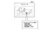
- “reflecting an abnormality in the simulator PLV” means that, as shown in FIG. 7, when the simulator PLV performs a simulated operation of an actual PLR, the type of abnormality specified in step S34 (for example, “Pipe A breakage”). )) is incorporated into the calculation of the simulation unit 1004. As a result, the simulator PLV can perform the simulated operation of the actual PLR in the state in which the abnormality (pipe A breakage) has occurred. In the process of the first step S35, the estimation unit 1003 randomly determines the “abnormality scale” to be reflected on the simulator PLV (for example, fracture area: 1.0 cm 2 or the like).
- the estimation unit 1003 reflects the type of abnormality (for example, the breakage of the pipe A) and the scale of the abnormality (for example, the breakage area: 1.0 cm 2 ) in the simulator PLV in step S35.
- the simulated operation from the time of abnormality occurrence (time tb) to the present time is executed.
- the estimation unit 1003 changes the scale of the abnormality reflected in the previous time (for example, the fracture area: 1.0 cm 2 ⁇ 2.0 cm 2 ) and then again from the abnormality occurrence time (time tb) to the present time. Perform simulated driving up to. This is repeated for variations of the preset abnormal scale.
- the estimation unit 1003 calculates the time series of the actual machine measured values up to the present time and the simulator calculated values of all the variations obtained by the simulated operation of the simulator PLV that reflects the occurrence of the abnormality from the abnormality occurrence time (time tb).
- the degree of similarity with the time series of is calculated (step S36).
- the size of the abnormality whose degree of similarity most closely matches the predetermined determination threshold is estimated as the size of the abnormality occurring in the actual PLR (step S37).
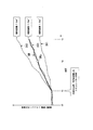
- the estimation unit 1003 executes the processes of steps S35 to S36 to change the value of the abnormality scale (for example, the fracture area of the pipe) based on each simulated operation, as shown in FIG. Gets the time series of multiple simulator calculated values. For example, in the example illustrated in FIG. 8, the estimation unit 1003 sets the simulator operation time series DV1 as a result of the simulated operation with the fracture area of “1.0 cm 2 ”and the simulated operation with the fracture area of “2.0 cm 2 ”.
- the estimation unit 1003 makes the determination in step S36 based on the high degree of similarity between the time series DV3 of the simulator calculated value and the time series DR of the actual machine measured value. Then, in step S37, the estimation unit 1003 acquires an estimation result of “breakage area: 1.5 cm 2 ”for the scale of abnormality that has occurred in the actual PLR.
- the estimation unit 1003 calculates the actual machine measurement value and the simulator calculation value acquired by the time (time tc) when a predetermined time has elapsed after the time ta when it is determined that an abnormality has occurred.
- the similarity is calculated by including it.
- the similarity determination is performed including the trend of the operating state after the time when the abnormality is detected, and therefore the estimation accuracy of the abnormality scale can be improved.
- the estimation unit 1003 resembles a time series of actual machine measured values obtained by the abnormality detection time (time ta) and a time series of simulator calculated values. You may calculate the degree. That is, the similarity determination may be performed by including the trend of the driving state before the time when the abnormality is detected.
- the notification processing unit 1002 notifies various information regarding the abnormality (step S38). For example, the notification processing unit 1002 notifies the operator of information such as the time of occurrence of an abnormality, the time of detection of the abnormality, the type of the abnormality, and the scale of the abnormality through the monitor 103 or the like (step S38).
- the simulator PLV abnormality detection device
- the simulator PLV acquires actual machine measured values from the actual machine PLR of the plant and acquires simulator calculated values from the simulator PLV that simulates the operation of the actual machine PLR of the plant.
- an abnormality determination unit 1001 that determines that an abnormality has occurred in the actual PLL when the degree of deviation of the actual measurement value from the acquired simulator calculation value exceeds a predetermined determination threshold, and an abnormality occurs.
- a notification processing unit 1002 for notifying that an abnormality has occurred.
- the simulator PLV according to the first embodiment further estimates, when the occurrence of an abnormality is detected, information about the abnormality that has occurred (abnormality occurrence time, abnormality type, abnormality scale). Equipped with. By doing so, the operator can grasp the information about the abnormality that has occurred, and can take prompt and appropriate action. Thereby, early convergence of the abnormality can be achieved.
- the estimation unit 1003 has a function of estimating an abnormality occurrence time and tracing the operating state of the actual PLR simulated by the simulator PLV back to the time of the abnormality occurrence time.
- the abnormality occurrence time is immediately before the difference between the simulator calculation value and the actual machine measurement value occurs, and the simulator calculation value calculated by the simulation unit 1004 at the abnormality occurrence time is a highly accurate reproduction of the operating state of the actual machine PLR. Since the estimation unit 1003 performs the multi-function injection on the highly accurately simulated operating state and estimates the type and scale of the abnormality, the estimation unit 1003 accurately estimates the type and scale of the abnormality occurring in the actual PLR. be able to.
- the simulation unit 1004 calculates the simulator calculation value based on the actual machine measured value and the control command, but since it does not have a function of determining that an abnormality has occurred, the actual machine measured value and the control command sent one after another.
- the operating state of the actual PLR is simulated so that Then, at least a part of the simulator calculated value gradually deviates from the actual operating state of the actual PLR, and the simulation accuracy decreases. For example, when using the simulator PLV for the purpose of monitoring, the operator refers to an incorrect simulator calculation value and monitors it.
- the estimation unit 1003 can specify the time (abnormality occurrence time) when the simulated operating state starts to deviate from the operating state of the actual PLR, and notify the simulation unit 1004 of the accident signal. Thereby, the continuation of the erroneous simulation by the simulation unit 1004 can be stopped.
- the time before the abnormality occurrence time can be determined as a period in which the value of the simulator calculation value is correct. The simulator-calculated value during the period when the value is determined to be correct can be useful for, for example, later analysis of abnormality occurrence.
- the process of each process in the simulator PLV (abnormality detection device) described above is stored in a computer readable recording medium in the form of a program, and the above process is performed by the computer reading and executing the program.
- the computer-readable recording medium refers to a magnetic disk, a magneto-optical disk, a CD-ROM, a DVD-ROM, a semiconductor memory, or the like.
- the computer program may be distributed to the computer via a communication line, and the computer that receives the distribution may execute the program.
- the program may be for realizing a part of the functions described above. Further, it may be a so-called difference file (difference program) that can realize the above-mentioned functions in combination with a program already recorded in the computer system. Further, the simulator PLV (abnormality detection device) may be composed of one computer, or may be composed of a plurality of computers communicably connected.
- the functions of the acquisition unit 1000, the abnormality determination unit 1001, the notification processing unit 1002, and the estimation unit 1003 may be provided in the control device 10.
- abnormality detection device simulator, plant monitoring system, abnormality detection method, and program, it is possible to accurately and early detect an abnormality in the actual machine using the simulator of the actual machine in the plant.
- Control device 100 CPU 1000 acquisition unit 1001 abnormality determination unit 1002 notification processing unit 1003 estimation unit 1004 simulation unit 101 memory 102 communication interface 103 monitor 104 input device 105 storage PLR actual device PLV simulator (abnormality detection device) DB anomaly estimation table
Landscapes
- Physics & Mathematics (AREA)
- General Physics & Mathematics (AREA)
- Engineering & Computer Science (AREA)
- Automation & Control Theory (AREA)
- Testing And Monitoring For Control Systems (AREA)
Abstract
異常を正確かつ早期に検出することができる異常検出装置を提供する。 異常検出装置(PLV)は、プラントの実機(PLR)から計測される実機計測値を取得し、制御装置(10)から制御指令を取得する取得部と、前記プラントの実機の状態を示すシミュレータ計算値を前記制御指令に基づいて算出するシミュレーション部と、算出した前記シミュレータ計算値に対する前記実機計測値の乖離の度合いが所定の判定閾値を上回った場合に、前記実機に異常が発生したと判定する異常判定部と、前記異常が発生したと判定された場合に、異常が発生したことを通知する通知処理部と、を備える。
Description
本発明は、異常検出装置、シミュレータ、プラント監視システム、異常検出方法及びプログラムに関する。
本願は、2019年2月7日に、日本に出願された特願2019-020252号に基づき優先権を主張し、その内容をここに援用する。
本願は、2019年2月7日に、日本に出願された特願2019-020252号に基づき優先権を主張し、その内容をここに援用する。
各種センサを通じてプラントの実機の動作状態をモニタリングし、現在のプラントの状態を判断したり、将来のプラントの状態を予測したりする場合がある。例えば、実機のモニタリングデータに基づいて将来の運転状況を予測する予測シミュレータを用いた運転支援装置が知られている。
また、特許文献1には、異常事象の識別結果に基づいて異常発生時刻推定方式を決定し、適合度および異常発生時刻推定方式に基づいて、識別された異常事象の発生時刻を推定する管路異常検知装置が開示されている。
プラントの実機の動作を、コンピュータ演算により忠実に模擬するシミュレータが知られている。このようなシミュレータを応用して、実機の異常を正確かつ早期に検出することが望まれている。
本発明は、上述の課題を解決することのできる異常検出装置、シミュレータ、プラント監視システム、異常検出方法及びプログラムを提供する。
本発明の一態様によれば、異常検出装置は、プラントの実機から実機計測値を取得し、前記プラントの制御装置から制御指令を取得する取得部と、前記プラントの実機の状態を示すシミュレータ計算値を前記制御指令に基づいて算出するシミュレーション部と、算出した前記シミュレータ計算値に対する前記実機計測値の乖離の度合いが所定の判定閾値を上回った場合に、前記実機に異常が発生したと判定する異常判定部と、前記異常が発生したと判定された場合に、異常が発生したことを通知する通知処理部と、前記異常が発生したと判定された場合に、当該判定がなされた時刻までの前記実機計測値の時系列に基づいて前記異常が発生した時刻を推定する推定部と、を備える。
本発明の一態様によれば、前記推定部が、前記異常が発生した時刻を推定すると、前記シミュレーション部は、前記シミュレータ計算値を、前記異常が発生した時刻における前記シミュレータ計算値の値に遡らせる。
本発明の一態様によれば、前記推定部は、更に、前記実機に異常が発生したと判定された時刻における前記実機計測値が満たす条件に基づいて、前記異常の種類を推定する。
本発明の一態様によれば、前記推定部は、更に、前記異常の発生を前記シミュレーション部に反映させたうえで、当該異常が発生した時刻から現在時刻までの模擬運転より得られたシミュレータ計算値の時系列に基づいて、前記異常の種類と規模を推定する。
本発明の一態様によれば、前記推定部は、少なくとも前記異常が発生したと判定された時刻の後、所定時間が経過した時刻までに取得された前記実機計測値の時系列、及び、前記シミュレータ計算値の時系列の類似度に基づいて、前記異常の種類と規模を推定する。
本発明の一態様によれば、前記推定部は、前記異常が発生した時刻を、前記実機計測値の時系列の変化率に基づいて推定する。
本発明の一態様によれば、シミュレータは、プラントの実機から実機計測値を取得し、前記プラントの制御装置から制御指令を取得する取得部と、前記プラントの実機の状態を示すシミュレータ計算値を前記制御指令に基づいて算出するシミュレーション部と、前記シミュレータ計算値に対する前記実機計測値の乖離の度合いが所定の判定閾値を上回った場合に、前記実機に異常が発生したと判定する異常判定部と、前記異常が発生したと判定された場合に、異常の発生をオペレータへ通知する通知処理部と、前記異常が発生したと判定された場合に、当該判定がなされた時刻までの前記実機計測値の時系列に基づいて前記異常が発生した時刻を推定する推定部と、を備える。
本発明の一態様によれば、プラント監視システムは、上述の制御装置と異常検出装置を備える。
本発明の一態様によれば、異常検出方法は、プラントの実機から実機計測値を取得し、前記プラントの制御装置から制御指令を取得するステップと、前記プラントの実機の状態を示すシミュレータ計算値を前記制御指令に基づいて算出するステップと、算出された前記シミュレータ計算値に対する前記実機計測値の乖離の度合いが所定の判定閾値を上回った場合に、前記実機に異常が発生したと判定するステップと、前記異常が発生したと判定された場合に、異常が発生したことを通知するステップと、前記異常が発生したと判定された場合に、当該判定がなされた時刻までの前記実機計測値の時系列に基づいて前記異常が発生した時刻を推定するステップと、を有する。
本発明の一態様によれば、プログラムは、異常検出装置のコンピュータに、プラントの実機から計測される実機計測値を取得し、前記プラントの制御装置から制御指令を取得するステップと、前記プラントの実機の状態を示すシミュレータ計算値を前記制御指令に基づいて算出するステップと、算出された前記シミュレータ計算値に対する前記実機計測値の乖離の度合いが所定の判定閾値を上回った場合に、前記実機に異常が発生したと判定するステップと、前記異常が発生したと判定された場合に、異常が発生したことを通知するステップと、前記異常が発生したと判定された場合に、当該判定がなされた時刻までの前記実機計測値の時系列に基づいて前記異常が発生した時刻を推定するステップと、を実行させる。
上記した異常検出装置、シミュレータ、プラント監視システム、異常検出方法及びプログラムによれば、プラントの実機のシミュレータを用いて、実機の異常を正確かつ早期に検出することができる。
<第1の実施形態>
以下、図1~図8を参照しながら、第1の実施形態に係るプラント監視システムについて詳細に説明する。
以下、図1~図8を参照しながら、第1の実施形態に係るプラント監視システムについて詳細に説明する。
(プラント監視システムの全体構成)
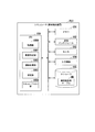
プラント監視システム1は、例えば、原子力発電プラントの実機PLRの運転を監視するシステムである。プラント監視システム1は、制御装置10と、シミュレータPLVとを備えている。
プラント監視システム1は、例えば、原子力発電プラントの実機PLRの運転を監視するシステムである。プラント監視システム1は、制御装置10と、シミュレータPLVとを備えている。
制御装置10は、プラントの実機PLRの運転を制御するための制御指令を出力する。また、制御装置10は、実機PLRに出力する制御指令と同じ信号を、シミュレータPLVにも出力する。制御装置10は、実機PLRから計測値(以下、「実機計測値」とも記載する。)を取得する。同様に、シミュレータPLVも実機計測値を取得する。シミュレータPLVは、自らが算出する実機PLRの運転状態を示す計算値(以下、「シミュレータ計算値」とも記載する。)を取得する。即ち、シミュレータPLVは、同一の制御指令に基づいてそれぞれ動作した実機PLR及びシミュレータPLVのそれぞれから、実機計測値及びシミュレータ計算値を取得する。シミュレータPLVは、取得した実機計測値及びシミュレータ計算値を対比することで実機PLRの異常を検出する異常検出装置としても機能する。
実機PLRは、タービンやボイラー、種々の配管からなる設備である。実機PLRの各所には、種々のセンサが設けられており、制御装置10は、これらのセンサを介して実機計測値を取得する。種々のセンサとは、配管の温度、圧力、流量等を計測可能な各種計器類、タンクの貯水量検出センサ、弁の開閉検知センサなどである。複数のセンサを通じて取得された実機計測値は、逐次、制御装置10及びシミュレータPLVによって取得される。
シミュレータPLVは、実機PLRのいわゆるデジタルツインであって、実体としては演算装置(コンピュータ)である。即ち、シミュレータPLVは、実機PLRの運転を模擬する実機シミュレーションモデルである。シミュレータPLVは、運転中の実機PLR内で生じる物理的現象を表す関数群によって構築される。シミュレータPLVは、制御装置10から受け付けた制御指令を組み入れて物理演算を行い、実機PLRの運転状態を模擬する。シミュレータPLVは、例えば、実機PLRの監視や運転訓練用途等で開発されたものであって、実機PLRとの整合性について実績があるシミュレーションモデルで構築されるのが好ましい。
実機PLRは、本実施形態においては原子力発電プラントに設置される装置、設備等を想定しているが、他の実施形態においては原子力以外の発電プラント(火力発電プラント等)であってもよいし、発電プラント以外のプラント(例えば、化学プラント、廃棄物処理プラント等)に設置される装置、設備等であってもよい。
(シミュレータの機能構成)
図2は、第1の実施形態に係るシミュレータの機能構成を示す図である。
図2に示すように、シミュレータPLVは、CPU100と、メモリ101と、通信インタフェース102と、モニタ103と、入力機器104と、ストレージ105とを備えている。
図2は、第1の実施形態に係るシミュレータの機能構成を示す図である。
図2に示すように、シミュレータPLVは、CPU100と、メモリ101と、通信インタフェース102と、モニタ103と、入力機器104と、ストレージ105とを備えている。
メモリ101は、いわゆる主記憶装置であって、CPU100がプログラムに基づいて動作するための命令及びデータが展開される。
通信インタフェース102は、シミュレータPLVの外部(実機PLR、制御装置10等)との通信を行うためのインタフェース機器である。
モニタ103は、情報を視認可能に表示する表示デバイスであって、例えば、液晶ディスプレイや有機ELディスプレイなどであってよい。
入力機器104は、シミュレータPLVの使用者の操作を受け付ける入力デバイスであって、例えば、一般的なマウス、キーボード、タッチセンサなどであってよい。
ストレージ105は、いわゆる補助記憶装置であって、例えば、HDD(Hard Disk Drive)、SSD(Solid State Drive)等であってよい。ストレージ105には、異常推定用テーブルDB(後述)が記録されている。
CPU100は、シミュレータPLVの動作全体の制御を司るプロセッサである。本実施形態に係るCPU100は、図2に示すように、取得部1000、異常判定部1001、通知処理部1002、推定部1003及び、シミュレーション部1004としての機能を発揮する。以下、CPU100が有する各機能について説明する。
取得部1000は、実機PLRに設けられた各種センサから実機計測値を取得する。また、取得部1000は、シミュレーション部1004からシミュレータ計算値を取得する。また、取得部1000は、制御装置10が実機PLRへ出力した制御指令を取得する。
異常判定部1001は、実機PLRの運転の異常の有無を判定する。具体的には、異常判定部1001は、取得部1000によって取得されたシミュレータ計算値に対する実機計測値の乖離の度合いが所定の判定閾値を上回った場合に、実機PLRに異常が発生したと判定する。
通知処理部1002は、異常判定部1001によって実機PLRの運転に異常が発生したと判定された場合に、モニタ103等を通じて、オペレータに向けて異常が発生したことを通知する。
推定部1003は、異常判定部1001によって実機PLRの運転に異常が発生したと判定された場合に、当該異常に関する種々の情報を推定する。具体的には、推定部1003は、実機PLRの運転に異常が発生したと判定された場合に、当該異常が発生した時刻、異常の種類、及び、異常の規模を推定する。推定部1003がこれら異常に関する情報を推定する処理の具体的態様については後述する。
シミュレーション部1004は、取得部1000が取得した実機計測値や制御指令を、プラントにおける物理的現象を表す関数群に反映させて物理演算を行い、シミュレータ計算値を算出する。関数群は、例えば、制御装置10が出力した制御指令の一部を入力すると、同様の制御指令を受けた実機PLRで計測される実機計測値と同じ値を出力する。シミュレーション部1004は、取得部1000を通じて最新の制御指令を取得し、その値を用いたシミュレータ計算値の算出を継続的に行う。シミュレーション部1004は、シミュレータ計算値の算出に実機計測値を用いてもよい。これにより、シミュレータPLVは、リアルタイムに実機PLRの運転状態を模擬するデジタルツインとして機能する。シミュレータ計算値には、実機のセンサが設置されていない箇所における監視対象の温度や圧力などの物理量が含まれる。オペレータは、シミュレータ計算値を参照することで、実機計測値だけからは得られない様々な情報を得ることができ、プラントの監視に役立てることができる。従って、シミュレーション部1004が出力するシミュレータ計算値をプラントの監視に用いる場合、シミュレータ計算値には、高いシミュレーション精度を維持することが求められる。
(シミュレータの処理フロー)
図3は、第1の実施形態に係るシミュレータの処理フローを示す図である。
また、図4~図8は、第1の実施形態に係るシミュレータの処理を詳細に説明するための図である。
図3は、第1の実施形態に係るシミュレータの処理フローを示す図である。
また、図4~図8は、第1の実施形態に係るシミュレータの処理を詳細に説明するための図である。
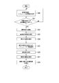
図3に示す処理フローは、実機PLRの運転中において、継続して繰り返し実行される。
まず、シミュレータPLVの取得部1000は、実機PLRの各種センサを通じて実機計測値を取得し、かつ、シミュレーション部1004からシミュレータ計算値を取得する(ステップS30)。シミュレータ計算値は、シミュレーション部1004が、取得部1000によって取得された制御指令等を用いて算出した物理量αである。この物理量αは、取得部1000が取得する実機計測値にも含まれている。
次に、シミュレータPLVの異常判定部1001は、ステップS30で取得した実機計測値とシミュレータ計算値との乖離の度合いを算出し、当該乖離の度合いが所定の判定閾値を上回っているか否かを判定する(ステップS31)。例えば、異常判定部1001は、物理量αの実機計測値と物理量αのシミュレータ計算値とを比較する。乖離の度合いが所定の判定閾値を上回っていない場合(ステップS31;NO)、異常判定部1001は、実機PLRに異常が発生していないと判定する。この場合、CPU100は、ステップS30の処理に戻る。
乖離の度合いが所定の判定閾値を上回っていた場合(ステップS31;YES)、実機PLRに異常が発生したと判定する。この場合、シミュレータPLVの通知処理部1002は、モニタ103等を通じてオペレータに異常の発生を通知する(ステップS32)。
図4を参照しながら、上述したステップS31~ステップS32の処理について詳しく説明する。
図4に示すグラフは、ある基準時刻t0から現在時刻(時刻ta)までに取得された実機計測値の時系列DR及びシミュレータ計算値の時系列DVを示している。図4においては、実機PLRから取得される一つのパラメータ(例えば、ある配管Aの圧力)についての実機計測値と、同一のパラメータ(配管Aの圧力)についてのシミュレータ計算値との対比を示している。本実施形態においては、実際には、複数種類のパラメータごとに、実機計測値及びシミュレータ計算値の対比がなされる。
図4に示すグラフは、ある基準時刻t0から現在時刻(時刻ta)までに取得された実機計測値の時系列DR及びシミュレータ計算値の時系列DVを示している。図4においては、実機PLRから取得される一つのパラメータ(例えば、ある配管Aの圧力)についての実機計測値と、同一のパラメータ(配管Aの圧力)についてのシミュレータ計算値との対比を示している。本実施形態においては、実際には、複数種類のパラメータごとに、実機計測値及びシミュレータ計算値の対比がなされる。
図4に示すように、ある時刻taに取得された実機計測値DRaとシミュレータ計算値DVaとの乖離の度合いg(g=|DRa-DVa|)が、判定閾値gthを上回ったとする(ステップS31;YES)。この場合、異常判定部1001は、実機PLRに異常が発生したと判定する。これにより、通知処理部1002は、時刻taにおいて、異常の発生を通知する(ステップS32)。つまり、時刻taにおいて、シミュレータPLV(異常検出装置)によって異常の発生が検出される。
図3に戻り、続いて、シミュレータPLVの推定部1003は、発生した異常に関する各種情報を推定すべく、以下の処理を実行する。
推定部1003は、異常発生時刻を推定する(ステップS33)。異常発生時刻とは、実機PLRにて実際に異常が発生した時刻であって、異常が検出された時刻(図4に示す時刻ta)よりも前の時刻となる。
図5を参照しながら、上述したステップS33の処理について詳しく説明する。
図5に示すグラフ5aは、図4と同様、ある基準時刻t0から現在時刻(時刻ta)までに取得された実機計測値の時系列DR及びシミュレータ計算値の時系列DVを示している。また、図5に示すグラフ5bは、実機計測値の時系列DRの時間微分である変化率ΔDRを示している。
図5に示すグラフ5aは、図4と同様、ある基準時刻t0から現在時刻(時刻ta)までに取得された実機計測値の時系列DR及びシミュレータ計算値の時系列DVを示している。また、図5に示すグラフ5bは、実機計測値の時系列DRの時間微分である変化率ΔDRを示している。
本実施形態においては、推定部1003は、所定の基準時刻t0から異常ありとの判定がなされた時刻(時刻ta)までの実機計測値の時系列DRに基づいて、実機PLRに異常が発生した時刻を推定する。具体的には、推定部1003は、時刻taまでの実機計測値の時系列DRの変化率ΔDRを算出し、更に、当該変化率ΔDRが所定の判定閾値ΔDRthを上回った時刻(時刻tb)を特定する。ここで、変化率ΔDRが判定閾値ΔDRthを上回った時刻tbは、実機計測値の時系列DRのトレンドの変化点とみなすことができる。したがって、推定部1003は、上記のように特定した時刻tbを、異常が発生した時刻として推定する。推定部1003は、シミュレーション部1004へ異常の発生を示す事故信号を通知する。事故信号を取得すると、シミュレーション部1004は、シミュレータ計算値の算出を一旦停止する。さらに推定部1003は、実機PLRの模擬状態を、時刻tbにおける実機PLRの運転状態に戻すようシミュレーション部1004へ指示する。シミュレーション部1004は、時刻tbにおけるシミュレータ計算値を再現する。例えば、シミュレーション部1004は、時刻ごとのシミュレータ計算値及び実機計測値及び制御指令を、その時刻と対応付けてストレージ105へ記録する。推定部1003から模擬状態を時刻tbへ戻すように指示を受けると、シミュレーション部1004は、ストレージ105から、時刻tbのシミュレータ計算値等を読み出して、時刻tbにおける実機PLRの運転状態を再現する。
図3に戻り、次に、推定部1003は、実機PLRで発生した異常の種類を判定する(ステップS34)。異常の種類とは、異常の態様、性質、発生個所等を特定する情報であり、例えば、「配管A破断」、「配管B閉塞」、「電磁弁X故障」等の情報である。
図6を参照しながら、上述したステップS34の処理について詳しく説明する。
図6に示す情報テーブルは、事前にストレージ105に格納された異常推定用テーブルDBの例である。図6に示すように、異常推定用テーブルDBは、予め規定した「異常の種類」毎に、複数種類の実機計測値が満たす条件の組み合わせが記録されている。図6に示した各条件T1、T2、・・、P1、P2、・・、F1、F2、・・は、各実機計測値DR_T、DR_P、DR_F、・・の範囲(〇〇以上、××以下)、或いは、各実機計測値DR_T、DR_P、DR_F、・・の変化量の範囲等で規定される。
図6に示す情報テーブルは、事前にストレージ105に格納された異常推定用テーブルDBの例である。図6に示すように、異常推定用テーブルDBは、予め規定した「異常の種類」毎に、複数種類の実機計測値が満たす条件の組み合わせが記録されている。図6に示した各条件T1、T2、・・、P1、P2、・・、F1、F2、・・は、各実機計測値DR_T、DR_P、DR_F、・・の範囲(〇〇以上、××以下)、或いは、各実機計測値DR_T、DR_P、DR_F、・・の変化量の範囲等で規定される。
推定部1003は、上述のステップS34において、異常推定用テーブルDBを参照して、現在時刻(時刻ta)までに取得した実機計測値の時系列DRが、各「異常の種類」ごとに規定された条件の組み合わせを満たしているか否かを判定する。例えば、推定部1003は、実機計測値DR_Tが条件T1を満たし、実機計測値DR_Pが条件P1を満たし、かつ、実機計測値DR_Fが条件F1を満たしていた場合には、実機PLRで事故事象X1(配管A破断)が発生したものと推定する。
なお、実機計測値の時系列の組み合わせによっては、異常推定用テーブルDBに規定された複数種類の条件の組み合わせが同時に当てはまる場合も想定される。例えば、ある実機計測値の時系列の組み合わせは、事故事象Xaの条件と、事故事象Xbの条件との両方を満たすことも考えられる。この場合、推定部1003は、実機PLRで「事故事象Xa、Xbの何れか一方又は両方が発生した。」と推定する。
図3に戻り、次に、推定部1003は、実機PLRで発生した異常の規模を推定するにあたり、以下に説明するステップS35~ステップS37の処理を行う。ステップS35の処理について、図7を参照しながら詳しく説明する。
初期状態において、シミュレータPLV(シミュレーション部1004)が物理演算により模擬する実機PLRの運転は、あくまで実機PLRに何らの異常が生じていない状態を前提として演算される。そのため、実機PLRに異常が発生した場合、当該異常が発生した実機PLRと、異常が発生していない前提で演算を行うシミュレータPLVとの間で、各々の運転状態に乖離が生じる。そこで、推定部1003は、当該異常が発生した時刻(ステップS33にて特定された時刻tb)に遡らせたシミュレータPLVに対し、ステップS34で特定された異常の種類を反映(マルファンクション投入)させて、模擬運転を再度やり直す(ステップS35)。
ここで、「異常をシミュレータPLVに反映させる」とは、図7に示すように、シミュレータPLVで実機PLRの模擬運転を行うにあたり、ステップS34で特定された異常の種類(例えば、「配管A破断」)が発生したことで引き起こされる物理的現象をシミュレーション部1004の演算に組み入れることである。これにより、シミュレータPLVは、当該異常(配管A破断)が発生した状態にある実機PLRの模擬運転が可能となる。
なお、最初のステップS35の処理においては、推定部1003は、シミュレータPLVに反映させる「異常の規模」を無作為に決定(例えば、破断面積:1.0cm2などと決定)する。
ここで、「異常をシミュレータPLVに反映させる」とは、図7に示すように、シミュレータPLVで実機PLRの模擬運転を行うにあたり、ステップS34で特定された異常の種類(例えば、「配管A破断」)が発生したことで引き起こされる物理的現象をシミュレーション部1004の演算に組み入れることである。これにより、シミュレータPLVは、当該異常(配管A破断)が発生した状態にある実機PLRの模擬運転が可能となる。
なお、最初のステップS35の処理においては、推定部1003は、シミュレータPLVに反映させる「異常の規模」を無作為に決定(例えば、破断面積:1.0cm2などと決定)する。
以上のようにして、推定部1003は、ステップS35にて、異常の種類(例えば、配管A破断)及び異常の規模(例えば、破断面積:1.0cm2)をシミュレータPLVに反映させたうえで、異常発生時刻(時刻tb)から現時点までの模擬運転を実行する。次に推定部1003は、前回に反映させた異常の規模を変更(例えば、破断面積:1.0cm2→2.0cm2と変更)したうえで、再度、異常発生時刻(時刻tb)から現時点までの模擬運転を行う。これをあらかじめ設定された異常の規模のバリエーション分繰り返す。
次に、推定部1003は、現時点までの実機計測値の時系列と、異常発生時刻(時刻tb)から当該異常の発生を反映させたシミュレータPLVの模擬運転によって得られた全バリエーションのシミュレータ計算値の時系列との類似度を算出する(ステップS36)。
両者の類似度が所定の判定閾値ともっとも整合した異常の規模を、実機PLRで発生している異常の規模として推定する(ステップS37)。
両者の類似度が所定の判定閾値ともっとも整合した異常の規模を、実機PLRで発生している異常の規模として推定する(ステップS37)。
図8を参照しながら、上述したステップS36~ステップS37の処理について詳しく説明する。
推定部1003は、ステップS35~ステップS36の処理を実行することで、図8に示すように、異常の規模(例えば、配管の破断面積)の値が変更されて実行された各模擬運転に基づく複数のシミュレータ計算値の時系列を取得する。例えば、図8に示す例では、推定部1003は、破断面積を“1.0cm2”として模擬運転した結果のシミュレータ計算値の時系列DV1と、破断面積を“2.0cm2”として模擬運転した結果のシミュレータ計算値の時系列DV2と、破断面積を“1.5cm2”として模擬運転した結果のシミュレータ計算値の時系列DV3と、を取得する。この場合、推定部1003は、シミュレータ計算値の時系列DV3と、実機計測値の時系列DRとの類似度が高いことをもってステップS36の判定を行う。そして、推定部1003は、ステップS37にて、実機PLRに発生した異常の規模について「破断面積:1.5cm2」なる推定結果を取得する。
推定部1003は、ステップS35~ステップS36の処理を実行することで、図8に示すように、異常の規模(例えば、配管の破断面積)の値が変更されて実行された各模擬運転に基づく複数のシミュレータ計算値の時系列を取得する。例えば、図8に示す例では、推定部1003は、破断面積を“1.0cm2”として模擬運転した結果のシミュレータ計算値の時系列DV1と、破断面積を“2.0cm2”として模擬運転した結果のシミュレータ計算値の時系列DV2と、破断面積を“1.5cm2”として模擬運転した結果のシミュレータ計算値の時系列DV3と、を取得する。この場合、推定部1003は、シミュレータ計算値の時系列DV3と、実機計測値の時系列DRとの類似度が高いことをもってステップS36の判定を行う。そして、推定部1003は、ステップS37にて、実機PLRに発生した異常の規模について「破断面積:1.5cm2」なる推定結果を取得する。
なお、図8に示す例では、推定部1003は、異常が発生したと判定された時刻taの後、所定時間が経過した時刻(時刻tc)までに取得された実機計測値及びシミュレータ計算値を含めて類似度を計算している。このようにすることで、異常が検出された時刻よりも後の運転状態のトレンドも含めて類似判定がなされるので、異常の規模の推定精度を高めることができる。ただし、他の実施形態ではこの態様に限定されず、例えば、推定部1003は、異常検出時刻(時刻ta)までに得られた実機計測値の時系列、及び、シミュレータ計算値の時系列の類似度を計算してもよい。つまり、異常が検出された時刻よりも前の運転状態のトレンドも含めて類似判定を行ってもよい。
次に、通知処理部1002が、異常に関する各種情報を通知する(ステップS38)。例えば、通知処理部1002は、モニタ103等を通じてオペレータに、異常の発生時刻、異常の検出時刻、異常の種類、異常の規模等の情報を通知する(ステップS38)。
(作用、効果)
以上のように、第1の実施形態に係るシミュレータPLV(異常検出装置)は、プラントの実機PLRから実機計測値を取得し、プラントの実機PLRの運転を模擬するシミュレータPLVからシミュレータ計算値を取得する取得部1000と、取得されたシミュレータ計算値に対する実機計測値の乖離の度合いが所定の判定閾値を上回った場合に、実機PLRに異常が発生したと判定する異常判定部1001と、異常が発生したと判定された場合に、異常が発生したことを通知する通知処理部1002と、を備える。
このようにすることで、異常が発生していない前提で演算されるシミュレータPLVの運転状態から外れたことをもって実機PLRの異常判定がなされるので、迅速かつ正確に異常の発生を検出することができる。
また、第1の実施形態に係るシミュレータPLVは、更に、異常の発生が検出された場合に、当該発生した異常に関する情報(異常発生時刻、異常の種類、異常の規模)を推定する推定部1003を備えている。
このようにすることで、オペレータは、発生した異常についての情報を把握することができ、迅速かつ適切な対応をとることができる。これにより、異常の早期収束を図ることができる。
このようにすることで、オペレータは、発生した異常についての情報を把握することができ、迅速かつ適切な対応をとることができる。これにより、異常の早期収束を図ることができる。
また、推定部1003は、異常発生時刻を推定し、シミュレータPLVが模擬する実機PLRの運転状態を、異常発生時刻の時点に遡らせる機能を有している。異常発生時刻は、シミュレータ計算値と実機計測値の乖離が生じる直前であり、異常発生時刻においてシミュレーション部1004が算出したシミュレータ計算値は、実機PLRの運転状態を高精度に再現したものである。推定部1003は、高精度に模擬された運転状態に対してマルファンクション投入を行い、異常の種類及び規模の推定を行うので、実機PLRで発生している異常の種類、規模を精度よく推定することができる。
また、シミュレーション部1004は、実機計測値及び制御指令に基づいてシミュレータ計算値の算出を行うが、異常が発生したことを判断する機能が無いため、次々と送られてくる実機計測値及び制御指令に合わせるように実機PLRの運転状態を模擬する。すると、シミュレータ計算値の少なくとも一部が、実際の実機PLRの運転状態から次第に乖離し、シミュレーション精度が低下することになる。例えば、監視の目的でシミュレータPLVを利用する場合には、オペレータは、誤ったシミュレータ計算値を参照して監視することになる。これに対し、推定部1003によれば、模擬した運転状態が実機PLRの運転状態から乖離し始める時刻(異常発生時刻)を特定し、シミュレーション部1004へ事故信号を通知することができる。これにより、シミュレーション部1004による誤ったシミュレーションの継続を停止させることができる。また、異常発生時刻以前を、シミュレータ計算値の値が正しい期間として確定することができる。値が正しいと確定された期間のシミュレータ計算値は、例えば、後に異常発生の解析などに役立てることができる。
なお、上述したシミュレータPLV(異常検出装置)における各処理の過程は、プログラムの形式でコンピュータ読み取り可能な記録媒体に記憶されており、このプログラムをコンピュータが読み出して実行することによって、上記処理が行われる。ここでコンピュータ読み取り可能な記録媒体とは、磁気ディスク、光磁気ディスク、CD-ROM、DVD-ROM、半導体メモリ等をいう。また、このコンピュータプログラムを通信回線によってコンピュータに配信し、この配信を受けたコンピュータが当該プログラムを実行するようにしてもよい。
また、上記プログラムは、前述した機能の一部を実現するためのものであってもよい。さらに、前述した機能をコンピュータシステムにすでに記録されているプログラムとの組み合わせで実現できるもの、いわゆる差分ファイル(差分プログラム)であってもよい。
また、シミュレータPLV(異常検出装置)は、1台のコンピュータで構成されていても良いし、通信可能に接続された複数のコンピュータで構成されていてもよい。
また、シミュレータPLV(異常検出装置)は、1台のコンピュータで構成されていても良いし、通信可能に接続された複数のコンピュータで構成されていてもよい。
その他、本発明の趣旨を逸脱しない範囲で、上記した実施の形態における構成要素を周知の構成要素に置き換えることは適宜可能である。また、この発明の技術範囲は上記の実施形態に限られるものではなく、本発明の趣旨を逸脱しない範囲において種々の変更を加えることが可能である。
例えば、取得部1000、異常判定部1001、通知処理部1002、推定部1003の機能を制御装置10に設けてもよい。
例えば、取得部1000、異常判定部1001、通知処理部1002、推定部1003の機能を制御装置10に設けてもよい。
上記した異常検出装置、シミュレータ、プラント監視システム、異常検出方法及びプログラムによれば、プラントの実機のシミュレータを用いて、実機の異常を正確かつ早期に検出することができる。
1 プラント監視システム
10 制御装置
100 CPU
1000 取得部
1001 異常判定部
1002 通知処理部
1003 推定部
1004 シミュレーション部
101 メモリ
102 通信インタフェース
103 モニタ
104 入力機器
105 ストレージ
PLR 実機
PLV シミュレータ(異常検出装置)
DB 異常推定用テーブル
10 制御装置
100 CPU
1000 取得部
1001 異常判定部
1002 通知処理部
1003 推定部
1004 シミュレーション部
101 メモリ
102 通信インタフェース
103 モニタ
104 入力機器
105 ストレージ
PLR 実機
PLV シミュレータ(異常検出装置)
DB 異常推定用テーブル
Claims (10)
- プラントの実機から実機計測値を取得し、前記プラントの制御装置から制御指令を取得する取得部と、
前記プラントの実機の状態を示すシミュレータ計算値を前記制御指令に基づいて算出するシミュレーション部と、
算出した前記シミュレータ計算値に対する前記実機計測値の乖離の度合いが所定の判定閾値を上回った場合に、前記実機に異常が発生したと判定する異常判定部と、
前記異常が発生したと判定された場合に、異常が発生したことを通知する通知処理部と、
前記異常が発生したと判定された場合に、当該判定がなされた時刻までの前記実機計測値の時系列に基づいて前記異常が発生した時刻を推定する推定部と、
を備える異常検出装置。 - 前記推定部が、前記異常が発生した時刻を推定すると、
前記シミュレーション部は、前記シミュレータ計算値を、前記異常が発生した時刻における前記シミュレータ計算値の値に遡らせる、
請求項1に記載の異常検出装置。 - 前記推定部は、更に、
前記実機に異常が発生したと判定された時刻における前記実機計測値が満たす条件に基づいて、前記異常の種類を推定する
請求項2に記載の異常検出装置。 - 前記推定部は、更に、
前記異常の発生を前記シミュレーション部に反映させたうえで、当該異常が発生した時刻から現在時刻までの模擬運転より得られたシミュレータ計算値の時系列に基づいて、前記異常の規模を推定する
請求項3に記載の異常検出装置。 - 前記推定部は、
少なくとも前記異常が発生したと判定された時刻の後、所定時間が経過した時刻までに取得された前記実機計測値の時系列、及び、前記シミュレータ計算値の時系列の類似度に基づいて、前記異常の規模を推定する
請求項4に記載の異常検出装置。 - 前記推定部は、前記異常が発生した時刻を、前記実機計測値の時系列の変化率に基づいて推定する、
請求項1から請求項5の何れか1項に記載の異常検出装置。 - プラントの実機から実機計測値を取得し、前記プラントの制御装置から制御指令を取得する取得部と、
前記プラントの実機の状態を示すシミュレータ計算値を前記制御指令に基づいて算出するシミュレーション部と、
前記シミュレータ計算値に対する前記実機計測値の乖離の度合いが所定の判定閾値を上回った場合に、前記実機に異常が発生したと判定する異常判定部と、
前記異常が発生したと判定された場合に、異常の発生をオペレータへ通知する通知処理部と、
前記異常が発生したと判定された場合に、当該判定がなされた時刻までの前記実機計測値の時系列に基づいて前記異常が発生した時刻を推定する推定部と、
を備えるシミュレータ。 - 請求項1から請求項6のいずれか一項に記載の異常検出装置と、
前記制御装置と、
を備えるプラント監視システム。 - プラントの実機から実機計測値を取得し、前記プラントの制御装置から制御指令を取得するステップと、
前記プラントの実機の状態を示すシミュレータ計算値を前記制御指令に基づいて算出するステップと、
算出された前記シミュレータ計算値に対する前記実機計測値の乖離の度合いが所定の判定閾値を上回った場合に、前記実機に異常が発生したと判定するステップと、
前記異常が発生したと判定された場合に、異常が発生したことを通知するステップと、
前記異常が発生したと判定された場合に、当該判定がなされた時刻までの前記実機計測値の時系列に基づいて前記異常が発生した時刻を推定するステップと、
を有する異常検出方法。 - 異常検出装置のコンピュータに、
プラントの実機から計測される実機計測値を取得し、前記プラントの制御装置から制御指令を取得するステップと、
前記プラントの実機の状態を示すシミュレータ計算値を前記制御指令に基づいて算出するステップと、
算出された前記シミュレータ計算値に対する前記実機計測値の乖離の度合いが所定の判定閾値を上回った場合に、前記実機に異常が発生したと判定するステップと、
前記異常が発生したと判定された場合に、異常が発生したことを通知するステップと、
前記異常が発生したと判定された場合に、当該判定がなされた時刻までの前記実機計測値の時系列に基づいて前記異常が発生した時刻を推定するステップと、
を実行させるプログラム。
Applications Claiming Priority (2)
| Application Number | Priority Date | Filing Date | Title |
|---|---|---|---|
| JP2019-020252 | 2019-02-07 | ||
| JP2019020252A JP7175786B2 (ja) | 2019-02-07 | 2019-02-07 | 異常検出装置、シミュレータ、プラント監視システム、異常検出方法及びプログラム |
Publications (1)
| Publication Number | Publication Date |
|---|---|
| WO2020162603A1 true WO2020162603A1 (ja) | 2020-08-13 |
Family
ID=71947473
Family Applications (1)
| Application Number | Title | Priority Date | Filing Date |
|---|---|---|---|
| PCT/JP2020/004842 WO2020162603A1 (ja) | 2019-02-07 | 2020-02-07 | 異常検出装置、シミュレータ、プラント監視システム、異常検出方法及びプログラム |
Country Status (2)
| Country | Link |
|---|---|
| JP (1) | JP7175786B2 (ja) |
| WO (1) | WO2020162603A1 (ja) |
Cited By (1)
| Publication number | Priority date | Publication date | Assignee | Title |
|---|---|---|---|---|
| CN115378819A (zh) * | 2021-05-19 | 2022-11-22 | 横河电机株式会社 | 网络模拟器、网络模拟方法和计算机可读记录介质 |
Citations (8)
| Publication number | Priority date | Publication date | Assignee | Title |
|---|---|---|---|---|
| JPS6421510A (en) * | 1987-07-16 | 1989-01-24 | Mitsubishi Electric Corp | Process abnormality diagnosing device |
| JPH05322604A (ja) * | 1992-05-21 | 1993-12-07 | Mitsubishi Heavy Ind Ltd | 異常同定装置 |
| JPH0674874A (ja) * | 1992-08-25 | 1994-03-18 | Mitsubishi Heavy Ind Ltd | 異常発生時間推定装置 |
| JPH06222191A (ja) * | 1993-01-28 | 1994-08-12 | Mitsubishi Electric Corp | プラント状態予測運転方法 |
| JPH113120A (ja) * | 1997-06-13 | 1999-01-06 | Teijin Seiki Co Ltd | サーボ制御システムの故障検出装置 |
| US20070192078A1 (en) * | 2006-02-14 | 2007-08-16 | Edsa Micro Corporation | Systems and methods for real-time system monitoring and predictive analysis |
| JP2016057650A (ja) * | 2014-09-05 | 2016-04-21 | 株式会社明電舎 | 時系列データの解析方法及び時系列データの異常監視装置 |
| JP2017002554A (ja) * | 2015-06-10 | 2017-01-05 | 株式会社日立製作所 | 管路異常検知装置および方法 |
Family Cites Families (3)
| Publication number | Priority date | Publication date | Assignee | Title |
|---|---|---|---|---|
| JP5322604B2 (ja) | 2008-11-26 | 2013-10-23 | 京セラ株式会社 | 無線通信装置 |
| CN104517275A (zh) | 2013-09-27 | 2015-04-15 | 株式会社理光 | 对象检测方法和系统 |
| JP6222191B2 (ja) | 2014-11-12 | 2017-11-01 | トヨタ自動車株式会社 | 燃料電池システム |
-
2019
- 2019-02-07 JP JP2019020252A patent/JP7175786B2/ja active Active
-
2020
- 2020-02-07 WO PCT/JP2020/004842 patent/WO2020162603A1/ja active Application Filing
Patent Citations (8)
| Publication number | Priority date | Publication date | Assignee | Title |
|---|---|---|---|---|
| JPS6421510A (en) * | 1987-07-16 | 1989-01-24 | Mitsubishi Electric Corp | Process abnormality diagnosing device |
| JPH05322604A (ja) * | 1992-05-21 | 1993-12-07 | Mitsubishi Heavy Ind Ltd | 異常同定装置 |
| JPH0674874A (ja) * | 1992-08-25 | 1994-03-18 | Mitsubishi Heavy Ind Ltd | 異常発生時間推定装置 |
| JPH06222191A (ja) * | 1993-01-28 | 1994-08-12 | Mitsubishi Electric Corp | プラント状態予測運転方法 |
| JPH113120A (ja) * | 1997-06-13 | 1999-01-06 | Teijin Seiki Co Ltd | サーボ制御システムの故障検出装置 |
| US20070192078A1 (en) * | 2006-02-14 | 2007-08-16 | Edsa Micro Corporation | Systems and methods for real-time system monitoring and predictive analysis |
| JP2016057650A (ja) * | 2014-09-05 | 2016-04-21 | 株式会社明電舎 | 時系列データの解析方法及び時系列データの異常監視装置 |
| JP2017002554A (ja) * | 2015-06-10 | 2017-01-05 | 株式会社日立製作所 | 管路異常検知装置および方法 |
Non-Patent Citations (1)
| Title |
|---|
| YAHATA, YOSHIHIKO ET AL.: "Adaptation of plant simulator for stable and safe operation, Solution: Advanced features and adaptive methods, Utilization of online /real-time driving support simulator, ''3. Summary of the mirror plant", INSTRUMENTATION CONTROL ENGINEERING, vol. 56, no. 2, 2013, pages 20 - 23 * |
Cited By (1)
| Publication number | Priority date | Publication date | Assignee | Title |
|---|---|---|---|---|
| CN115378819A (zh) * | 2021-05-19 | 2022-11-22 | 横河电机株式会社 | 网络模拟器、网络模拟方法和计算机可读记录介质 |
Also Published As
| Publication number | Publication date |
|---|---|
| JP7175786B2 (ja) | 2022-11-21 |
| JP2020129158A (ja) | 2020-08-27 |
Similar Documents
| Publication | Publication Date | Title |
|---|---|---|
| JP5901140B2 (ja) | システムの高い可用性のためにセンサデータを補間する方法、コンピュータプログラム、システム。 | |
| US7702485B2 (en) | Method and apparatus for predicting remaining useful life for a computer system | |
| WO2017115162A1 (en) | Method and system for testing distributed control systems of industrial plants | |
| JP5025776B2 (ja) | 異常診断フィルタ生成装置 | |
| US7470103B2 (en) | Method for determining limit exceedance | |
| WO2016195092A1 (ja) | 異常検知装置 | |
| JP6758155B2 (ja) | プラントの診断システム及び診断方法 | |
| WO2020162603A1 (ja) | 異常検出装置、シミュレータ、プラント監視システム、異常検出方法及びプログラム | |
| JP5614446B2 (ja) | システム信頼性評価装置 | |
| JP2009282804A (ja) | 比較判定装置及び比較判定方法 | |
| CN113553765A (zh) | 锅炉运行过程的动态仿真模拟方法、装置及系统 | |
| JP2021174397A (ja) | 制御支援装置、制御支援方法、制御支援プログラム、および制御システム | |
| Dal Vernon et al. | Work domain analysis and sensors I: principles and simple example | |
| An et al. | Detection of process anomalies using an improved statistical learning framework | |
| US20190162632A1 (en) | Failure mode specifying system, failure mode specifying method, and program | |
| JP6803788B2 (ja) | 情報処理装置、情報処理方法およびプログラム | |
| WO2016174958A1 (ja) | 漏水発生位置推定装置、システムおよび方法 | |
| JP2011123187A (ja) | 運転模擬装置 | |
| GB2536567A (en) | System for supporting operation during plant accidents and method for supporting operation during plant accidents | |
| EP4224380A1 (en) | Maintenance simulation device and maintenance simulation method | |
| KR102517226B1 (ko) | 디지털 트윈 시뮬레이터 및 그 디지털 트윈 시뮬레이터의 제어 방법 | |
| JP2022161488A (ja) | ビル管理システムおよび制御方法 | |
| Nystad | Technical condition indexes and remaining useful life of aggregated systems | |
| WO2024047859A1 (ja) | 異常検知装置、異常検知方法、および、異常検知プログラム | |
| JP6964423B2 (ja) | プラント運転シミュレーション装置、プラント運転シミュレーション方法及びプログラム |
Legal Events
| Date | Code | Title | Description |
|---|---|---|---|
| 121 | Ep: the epo has been informed by wipo that ep was designated in this application |
Ref document number: 20752916 Country of ref document: EP Kind code of ref document: A1 |
|
| NENP | Non-entry into the national phase |
Ref country code: DE |
|
| 122 | Ep: pct application non-entry in european phase |
Ref document number: 20752916 Country of ref document: EP Kind code of ref document: A1 |