WO2020162274A1 - 樹脂組成物充填済みシリンジ及びその保存方法 - Google Patents
樹脂組成物充填済みシリンジ及びその保存方法 Download PDFInfo
- Publication number
- WO2020162274A1 WO2020162274A1 PCT/JP2020/003084 JP2020003084W WO2020162274A1 WO 2020162274 A1 WO2020162274 A1 WO 2020162274A1 JP 2020003084 W JP2020003084 W JP 2020003084W WO 2020162274 A1 WO2020162274 A1 WO 2020162274A1
- Authority
- WO
- WIPO (PCT)
- Prior art keywords
- resin composition
- syringe
- filled
- volume
- meth
- Prior art date
- Legal status (The legal status is an assumption and is not a legal conclusion. Google has not performed a legal analysis and makes no representation as to the accuracy of the status listed.)
- Ceased
Links
Images


Classifications
-
- C—CHEMISTRY; METALLURGY
- C08—ORGANIC MACROMOLECULAR COMPOUNDS; THEIR PREPARATION OR CHEMICAL WORKING-UP; COMPOSITIONS BASED THEREON
- C08G—MACROMOLECULAR COMPOUNDS OBTAINED OTHERWISE THAN BY REACTIONS ONLY INVOLVING UNSATURATED CARBON-TO-CARBON BONDS
- C08G59/00—Polycondensates containing more than one epoxy group per molecule; Macromolecules obtained by polymerising compounds containing more than one epoxy group per molecule using curing agents or catalysts which react with the epoxy groups
- C08G59/18—Macromolecules obtained by polymerising compounds containing more than one epoxy group per molecule using curing agents or catalysts which react with the epoxy groups ; e.g. general methods of curing
- C08G59/40—Macromolecules obtained by polymerising compounds containing more than one epoxy group per molecule using curing agents or catalysts which react with the epoxy groups ; e.g. general methods of curing characterised by the curing agents used
- C08G59/50—Amines
- C08G59/5033—Amines aromatic
-
- B—PERFORMING OPERATIONS; TRANSPORTING
- B05—SPRAYING OR ATOMISING IN GENERAL; APPLYING FLUENT MATERIALS TO SURFACES, IN GENERAL
- B05C—APPARATUS FOR APPLYING FLUENT MATERIALS TO SURFACES, IN GENERAL
- B05C5/00—Apparatus in which liquid or other fluent material is projected, poured or allowed to flow on to the surface of the work
- B05C5/02—Apparatus in which liquid or other fluent material is projected, poured or allowed to flow on to the surface of the work the liquid or other fluent material being discharged through an outlet orifice by pressure, e.g. from an outlet device in contact or almost in contact, with the work
-
- B—PERFORMING OPERATIONS; TRANSPORTING
- B05—SPRAYING OR ATOMISING IN GENERAL; APPLYING FLUENT MATERIALS TO SURFACES, IN GENERAL
- B05C—APPARATUS FOR APPLYING FLUENT MATERIALS TO SURFACES, IN GENERAL
- B05C17/00—Hand tools or apparatus using hand held tools, for applying liquids or other fluent materials to, for spreading applied liquids or other fluent materials on, or for partially removing applied liquids or other fluent materials from, surfaces
- B05C17/005—Hand tools or apparatus using hand held tools, for applying liquids or other fluent materials to, for spreading applied liquids or other fluent materials on, or for partially removing applied liquids or other fluent materials from, surfaces for discharging material from a reservoir or container located in or on the hand tool through an outlet orifice by pressure without using surface contacting members like pads or brushes
- B05C17/00593—Hand tools of the syringe type
-
- B—PERFORMING OPERATIONS; TRANSPORTING
- B05—SPRAYING OR ATOMISING IN GENERAL; APPLYING FLUENT MATERIALS TO SURFACES, IN GENERAL
- B05D—PROCESSES FOR APPLYING FLUENT MATERIALS TO SURFACES, IN GENERAL
- B05D1/00—Processes for applying liquids or other fluent materials
- B05D1/26—Processes for applying liquids or other fluent materials performed by applying the liquid or other fluent material from an outlet device in contact with, or almost in contact with, the surface
-
- B—PERFORMING OPERATIONS; TRANSPORTING
- B05—SPRAYING OR ATOMISING IN GENERAL; APPLYING FLUENT MATERIALS TO SURFACES, IN GENERAL
- B05D—PROCESSES FOR APPLYING FLUENT MATERIALS TO SURFACES, IN GENERAL
- B05D3/00—Pretreatment of surfaces to which liquids or other fluent materials are to be applied; After-treatment of applied coatings, e.g. intermediate treating of an applied coating preparatory to subsequent applications of liquids or other fluent materials
-
- C—CHEMISTRY; METALLURGY
- C08—ORGANIC MACROMOLECULAR COMPOUNDS; THEIR PREPARATION OR CHEMICAL WORKING-UP; COMPOSITIONS BASED THEREON
- C08F—MACROMOLECULAR COMPOUNDS OBTAINED BY REACTIONS ONLY INVOLVING CARBON-TO-CARBON UNSATURATED BONDS
- C08F222/00—Copolymers of compounds having one or more unsaturated aliphatic radicals, each having only one carbon-to-carbon double bond, and at least one being terminated by a carboxyl radical and containing at least one other carboxyl radical in the molecule; Salts, anhydrides, esters, amides, imides, or nitriles thereof
- C08F222/10—Esters
- C08F222/1006—Esters of polyhydric alcohols or polyhydric phenols
- C08F222/102—Esters of polyhydric alcohols or polyhydric phenols of dialcohols, e.g. ethylene glycol di(meth)acrylate or 1,4-butanediol dimethacrylate
-
- C—CHEMISTRY; METALLURGY
- C08—ORGANIC MACROMOLECULAR COMPOUNDS; THEIR PREPARATION OR CHEMICAL WORKING-UP; COMPOSITIONS BASED THEREON
- C08G—MACROMOLECULAR COMPOUNDS OBTAINED OTHERWISE THAN BY REACTIONS ONLY INVOLVING UNSATURATED CARBON-TO-CARBON BONDS
- C08G59/00—Polycondensates containing more than one epoxy group per molecule; Macromolecules obtained by polymerising compounds containing more than one epoxy group per molecule using curing agents or catalysts which react with the epoxy groups
- C08G59/18—Macromolecules obtained by polymerising compounds containing more than one epoxy group per molecule using curing agents or catalysts which react with the epoxy groups ; e.g. general methods of curing
- C08G59/20—Macromolecules obtained by polymerising compounds containing more than one epoxy group per molecule using curing agents or catalysts which react with the epoxy groups ; e.g. general methods of curing characterised by the epoxy compounds used
- C08G59/22—Di-epoxy compounds
- C08G59/24—Di-epoxy compounds carbocyclic
- C08G59/245—Di-epoxy compounds carbocyclic aromatic
-
- C—CHEMISTRY; METALLURGY
- C08—ORGANIC MACROMOLECULAR COMPOUNDS; THEIR PREPARATION OR CHEMICAL WORKING-UP; COMPOSITIONS BASED THEREON
- C08K—Use of inorganic or non-macromolecular organic substances as compounding ingredients
- C08K3/00—Use of inorganic substances as compounding ingredients
- C08K3/34—Silicon-containing compounds
- C08K3/36—Silica
-
- C—CHEMISTRY; METALLURGY
- C08—ORGANIC MACROMOLECULAR COMPOUNDS; THEIR PREPARATION OR CHEMICAL WORKING-UP; COMPOSITIONS BASED THEREON
- C08K—Use of inorganic or non-macromolecular organic substances as compounding ingredients
- C08K5/00—Use of organic ingredients
- C08K5/04—Oxygen-containing compounds
- C08K5/14—Peroxides
-
- C—CHEMISTRY; METALLURGY
- C08—ORGANIC MACROMOLECULAR COMPOUNDS; THEIR PREPARATION OR CHEMICAL WORKING-UP; COMPOSITIONS BASED THEREON
- C08K—Use of inorganic or non-macromolecular organic substances as compounding ingredients
- C08K9/00—Use of pretreated ingredients
- C08K9/04—Ingredients treated with organic substances
- C08K9/06—Ingredients treated with organic substances with silicon-containing compounds
-
- C—CHEMISTRY; METALLURGY
- C08—ORGANIC MACROMOLECULAR COMPOUNDS; THEIR PREPARATION OR CHEMICAL WORKING-UP; COMPOSITIONS BASED THEREON
- C08L—COMPOSITIONS OF MACROMOLECULAR COMPOUNDS
- C08L33/00—Compositions of homopolymers or copolymers of compounds having one or more unsaturated aliphatic radicals, each having only one carbon-to-carbon double bond, and only one being terminated by only one carboxyl radical, or of salts, anhydrides, esters, amides, imides or nitriles thereof; Compositions of derivatives of such polymers
-
- C—CHEMISTRY; METALLURGY
- C08—ORGANIC MACROMOLECULAR COMPOUNDS; THEIR PREPARATION OR CHEMICAL WORKING-UP; COMPOSITIONS BASED THEREON
- C08L—COMPOSITIONS OF MACROMOLECULAR COMPOUNDS
- C08L63/00—Compositions of epoxy resins; Compositions of derivatives of epoxy resins
-
- C—CHEMISTRY; METALLURGY
- C08—ORGANIC MACROMOLECULAR COMPOUNDS; THEIR PREPARATION OR CHEMICAL WORKING-UP; COMPOSITIONS BASED THEREON
- C08L—COMPOSITIONS OF MACROMOLECULAR COMPOUNDS
- C08L33/00—Compositions of homopolymers or copolymers of compounds having one or more unsaturated aliphatic radicals, each having only one carbon-to-carbon double bond, and only one being terminated by only one carboxyl radical, or of salts, anhydrides, esters, amides, imides or nitriles thereof; Compositions of derivatives of such polymers
- C08L33/04—Homopolymers or copolymers of esters
- C08L33/06—Homopolymers or copolymers of esters of esters containing only carbon, hydrogen and oxygen, which oxygen atoms are present only as part of the carboxyl radical
- C08L33/062—Copolymers with monomers not covered by C08L33/06
- C08L33/064—Copolymers with monomers not covered by C08L33/06 containing anhydride, COOH or COOM groups, with M being metal or onium-cation
Definitions
- One aspect of the present disclosure relates to a syringe filled with a resin composition and a storage method thereof.
- Viscous materials such as sealants for machine parts or electronic parts, adhesives, pastes for forming electric/electronic circuits, and solders for mounting electronic parts are used with a syringe in order to be supplied to minute specific parts of an object. May be supplied.
- the viscous material is intermittently discharged from the syringe. This may cause discharge shortage in which a part where the viscous material is not supplied to the object is generated, which may cause a defect in joining or the like.
- Patent Document 1 discloses a technique for preventing gas from being mixed into a viscous material when filling a viscous material such as a resin composition into a syringe.
- the viscous material such as the resin composition may be filled in the syringe in advance. That is, the syringe filled with the resin composition may be stored or transported. The volume of the resin composition filled in the syringe may change due to temperature changes during storage or transportation. In this case, air may be mixed in the resin composition filled in the syringe. This causes intermittent ejection or ejection interruption.
- one object of the present disclosure is to provide a resin composition-filled syringe capable of suppressing the mixture of air, which causes the resin composition to be intermittently discharged from the syringe, and a storage method thereof. Especially.
- a resin composition-filled syringe according to the first aspect of the present disclosure includes a syringe, a resin composition filled in the syringe, and a plunger, and the resin composition contains a void, and the resin composition
- the volume ratio of the void to the volume of the object is 1.0 volume ppm to 520 volume ppm, and the maximum diameter of the void is 2,500 ⁇ m or less.
- the method for storing a resin composition-filled syringe according to the second aspect of the present disclosure includes storing the resin composition-filled syringe at ⁇ 80° C. to 0° C.
- a resin composition-filled syringe capable of suppressing the mixture of air, which causes the resin composition to be intermittently discharged from the syringe, and a storage method thereof. can do.
- FIG. 1 is a cross-sectional view showing a schematic configuration of a resin composition-filled syringe according to the first embodiment of the present disclosure.
- FIG. 2 is a photograph showing the state of the resin composition continuously discharged from the resin composition-filled syringe of Example 1.
- FIG. 3 is a photograph showing a state of the resin composition intermittently discharged from the resin composition-filled syringe of Comparative Example 1, that is, a state in which discharge shortage has occurred.
- the resin composition-filled syringe according to the first embodiment of the present disclosure includes a syringe, a resin composition filled in the syringe, and a plunger.
- the resin composition contains voids.
- the volume ratio of the voids to the volume of the resin composition is 1.0 volume ppm to 520 volume ppm.
- the maximum diameter of the void is 2,500 ⁇ m or less.
- the void means a space portion in the resin composition.
- the volume of the voids contained in the resin composition filled in the syringe is determined by an X-ray industrial computer tomography apparatus (hereinafter, also referred to as “industrial X-ray CT apparatus”) (for example, RF Co., Ltd., trade name: NAOMi-). CT).
- industrial X-ray CT apparatus for example, RF Co., Ltd., trade name: NAOMi-.
- CT X-ray industrial computer tomography apparatus
- the inside of the syringe is scanned with an imaging resolution of 0.068 mm using an industrial X-ray CT apparatus.
- a scan image is obtained.
- the diameter of the void filled in the syringe is visually measured.
- the volume of each void can be calculated from the measured diameter.
- the volume ratio of voids contained in the resin composition filled in the syringe can be calculated as follows.
- the maximum diameter of the voids contained in the resin composition filled in the syringe is, for example, a straight line of the maximum length of each void in the voids that can be confirmed from the image obtained by the scan using the industrial X-ray CT apparatus described above. Of the distances, it means the largest straight line distance.
- the maximum length linear distance was measured for all voids in the syringe in the scanned image. The longest straight line distance in the measured straight line distances was defined as the maximum diameter.
- the linear distance of the maximum length of all the voids in the syringe in the scan image was measured. The value obtained by dividing the total value of the linear distances of the maximum lengths of the voids by the number of voids was taken as the average diameter of the voids.
- the resin composition filled in the syringe may be frozen at a temperature of 0°C or lower in order to maintain the stability of the resin composition during storage or transportation.
- the resin composition is frozen, the reaction of the resin composition during storage or transportation is suppressed. Therefore, the resin composition can be maintained in a stable state.
- the volume of the resin composition filled in the syringe shrinks as the temperature changes due to freezing. Therefore, a gap may be formed between the inner wall of the syringe and the resin composition whose volume is shrunk by freezing.
- the resin composition in the syringe is thawed during use, the volume of the resin composition expands with the thaw.
- the air existing in the gap between the resin composition that has been volume-shrinked during freezing and the inner wall of the syringe is mixed in the thawed resin composition. If air is mixed into the resin composition during thawing, this air may cause intermittent discharge or discharge interruption when the resin composition is discharged from the syringe.
- FIG. 1 is a sectional view showing a schematic configuration of a resin composition-filled syringe according to the first embodiment of the present disclosure.
- the resin composition-filled syringe includes a syringe 1, a resin composition 2 filled in the syringe 1, and a plunger 3 inserted in the syringe 1.
- the resin composition 2 filled in the syringe 1 contains a plurality of voids 4.
- the syringe 1 has a reduced-diameter opening 11 at one end thereof. Further, the syringe 1 has an opening 12 at the other end facing the opening 11.
- a plunger rod is inserted into the opening 12.
- a flange 13 may be provided around the opening 12.
- the diameter-reduced opening 11 may be provided with a tip cap 21 that closes the opening 11.
- the opening 12 into which the plunger rod is inserted may be provided with a head cap 22 that closes the opening 12.
- the volume ratio of voids to the volume of the resin composition 2 filled in the syringe is 1.0 volume ppm to 520 volume ppm.
- the resin composition 2 contains small voids 4 having a maximum diameter of 2,500 ⁇ m or less. In this way, the resin composition 2 filled in the syringe contains the small voids 4. This makes it possible to reduce the difference between the volume change of the resin composition and the volume change of the syringe due to the temperature change during storage or transportation. Therefore, it is possible to prevent air having a size that causes intermittent ejection or discharge interruption from being mixed into the resin composition. For example, when the syringe filled with the resin composition is frozen at a temperature of 0° C.
- the volume shrinkage of the resin composition is larger than the volume shrinkage of the syringe itself.
- the frozen resin composition peels off from the inner wall of the syringe, and a gap is easily formed between the resin composition and the inner wall of the syringe. ..
- the resin composition 2 filled in the syringe has a volume ratio of 1.0 volume ppm to 520 volume ppm and can previously contain a small void 4 having a maximum diameter of 2,500 ⁇ m or less.
- the volume ratio of voids contained in the resin composition filled in the syringe is more preferably 1.0 volume ppm to 510 volume ppm with respect to the volume of the resin composition filled in the syringe, and further preferably Is 1.0 volume ppm to 505 volume ppm.
- the volume ratio of the voids contained in the resin composition is less than 1.0 volume ppm with respect to the volume of the resin composition filled in the syringe, the volume ratio of the voids previously contained in the resin composition. Is too few. Therefore, it becomes difficult to suppress the volume shrinkage of the resin composition during freezing. Therefore, it is difficult to suppress the contraction of the resin composition from the inner wall of the syringe.
- the volume ratio of the voids contained in the resin composition exceeds 520 ppm by volume with respect to the volume of the resin composition filled in the syringe, the size of the mixed voids may increase. Therefore, when the resin composition is discharged from the syringe, the discharge may be unspecific.
- the maximum diameter of the voids contained in the resin composition filled in the syringe is more preferably 2,400 ⁇ m or less, still more preferably 2,300 ⁇ m or less, still more preferably 2,200 ⁇ m or less.
- the lower limit of the maximum diameter of the void contained in the resin composition filled in the syringe is not particularly limited.
- the maximum diameter of the void contained in the resin composition filled in the syringe is generally 100 ⁇ m or more.
- the average diameter of the voids contained in the resin composition filled in the syringe when the volume ratio of the voids is 1.0 volume ppm to 520 volume ppm and the maximum diameter of the voids is 2,500 ⁇ m or less, the average diameter of the voids. May be 200 ⁇ m to 400 ⁇ m, or 250 ⁇ m to 350 ⁇ m.
- the average diameter of the voids contained in the resin composition filled in the syringe is 200 ⁇ m to 400 ⁇ m, the volume change of the resin composition due to the temperature change can be suppressed. This makes it possible to reduce the difference between the volume change of the resin composition and the volume change of the syringe due to the temperature change. Therefore, it is possible to suppress the mixture of air that becomes a large void that causes intermittent ejection or ejection interruption.
- voids can be contained in the resin composition by kneading the resin composition in a 300 g batch for 20 minutes using a three-roll mill. After that, a hard mixer defoams large voids from the resin composition. Further, using a centrifuge (for example, UFO-15, manufactured by Nippon Sosei Industry Co., Ltd.), the resin composition is centrifuged at 100 rpm for revolution and 1000 rpm for revolution for a predetermined time.
- a centrifuge for example, UFO-15, manufactured by Nippon Sosei Industry Co., Ltd.
- the volume ratio of voids to the volume of the resin composition filled in the syringe is 1.0 volume ppm to 520 volume ppm. Therefore, the resin composition can contain small voids having a maximum diameter of 2,500 ⁇ m or less.
- the resin composition is prepared by using a hard mixer (for example, a product name UV10L manufactured by Nippon Sosei Industry Co., Ltd.). Stir at 50-150 Pa and 40 rpm for an arbitrary time.
- the volume ratio of voids to the volume of the resin composition filled in the syringe is 1.0 volume ppm to 520 volume ppm. Therefore, the resin composition can contain small voids having a maximum diameter of 2,500 ⁇ m or less.
- the resin composition filled in the syringe preferably contains at least one resin selected from epoxy resin and acrylic resin. At least one resin selected from an epoxy resin and an acrylic resin is used as a material such as a sealant for machine parts or electronic parts, an adhesive, and an electric/electronic circuit forming paste.
- the epoxy resin is preferably liquid at room temperature, but may be solid at room temperature.
- the epoxy resin that is solid at room temperature can be used in a liquid state by diluting it with a liquid epoxy resin, a solvent or a diluent.
- the epoxy resin has a taste of having at least one epoxy group or glycidyl group in the molecule.
- the epoxy resin include bisphenol A type epoxy resin, bisphenol F type epoxy resin and derivatives thereof (for example, alkylene oxide adducts), hydrogenated bisphenol A type epoxy resin, hydrogenated bisphenol F type epoxy resin, brominated bisphenol.
- One of these epoxy resins may be used alone, or two or more thereof may be used in combination.
- the acrylic resin is preferably a (meth)acrylic resin, which means a compound having a (meth)acryloyl group in the molecule.
- the (meth)acrylic resin include methyl (meth)acrylate, ethyl (meth)acrylate, n-butyl (meth)acrylate, isobutyl (meth)acrylate, tertiary butyl (meth)acrylate, isodecyl (meth)acrylate, Lauryl (meth)acrylate, tridecyl (meth)acrylate, cetyl (meth)acrylate, stearyl (meth)acrylate, isoamyl (meth)acrylate, isostearyl (meth)acrylate, behenyl (meth)acrylate, 2-ethylhexyl (meth)acrylate , Other alkyl (meth) acrylate, cyclohexyl (meth) acrylate, tertiary butyl cycl
- examples of the (meth)acrylic resin include (meth)acrylamide.
- (Meth)acrylamides include, for example, N,N'-methylenebis(meth)acrylamide, N,N'-ethylenebis(meth)acrylamide, and 1,2-di(meth)acrylamide ethylene glycol.
- One of these acrylic resins may be used alone, or two or more thereof may be used in combination.
- acrylic resins include poly(meth)acrylate.
- poly(meth)acrylate a copolymer of (meth)acrylic acid and (meth)acrylate, or a copolymer of (meth)acrylate having a hydroxyl group and (meth)acrylate having no polar group, etc.
- acrylic resin examples include (meth)acrylate having a hydroxyl group.
- Examples of the (meth)acrylate having a hydroxyl group include 2-hydroxyethyl (meth)acrylate, 2-hydroxypropyl (meth)acrylate, 3-hydroxypropyl (meth)acrylate, 2-hydroxybutyl (meth)acrylate and 3- Hydroxybutyl (meth)acrylate, 4-hydroxybutyl (meth)acrylate, 1,2-cyclohexanediol mono(meth)acrylate, 1,3-cyclohexanediol mono(meth)acrylate, 1,4-cyclohexanediol mono(meth) Acrylate, 1,2-cyclohexanedimethanol mono(meth)acrylate, 1,3-cyclohexanedimethanol mono(meth)acrylate, 1,4-cyclohexanedimethanol mono(meth)acrylate, 1,2-cyclohexanediethanol mono(meth)acrylate ) Acrylate, 1,3-cyclohexanediethanol mono(meth)
- the acrylic resin includes, for example, a (meth)acrylate having a carboxy group, which is obtained by reacting the above-mentioned (meth)acrylate having a hydroxyl group with dicarboxylic acid or a derivative thereof.
- dicarboxylic acid examples include oxalic acid, malonic acid, succinic acid, glutaric acid, adipic acid, pimelic acid, suberic acid, azelaic acid, sebacic acid, maleic acid, fumaric acid, phthalic acid, and tetrahydrophthalic acid. Acids, hexahydrophthalic acid, and derivatives thereof.
- One of these acrylic resins may be used alone, or two or more thereof may be used in combination.
- the resin composition filled in the syringe is a filler, a curing agent, a solvent, a reactive diluent, an elastomer, a coupling agent, a flux agent, and a defoaming agent, in addition to at least one resin selected from an epoxy resin and an acrylic resin. At least one selected from the group consisting of agents, surface modifiers, rheology modifiers, colorants, plasticizers, or dispersants may be included.
- Viscosity of less than 200 Pa ⁇ s in the resin composition filled in the syringe is measured at 25° C. at a rotation speed of 50 rpm using a rotational viscometer, and the result is 2.5 Pa ⁇ s to 650 Pa ⁇ s. Is preferred. Further, the viscosity of 200 Pa ⁇ s or more in the resin composition filled in the syringe was measured at 25° C. at a rotation speed of 10 rpm using a rotational viscometer, and the result was 2.5 Pa ⁇ s to 650 Pa ⁇ s. It is preferable to have.
- the volume ratio of voids to the volume of the resin composition is 1.0 volume ppm to 520 volume ppm by the above method.
- the syringe can be filled with the resin composition so that the maximum diameter of the void becomes 2,500 ⁇ m or less.
- a rotational viscometer RV type spindle SC -14
- a rotational viscometer HBDV-1 spindle SC4-14
- a rotational viscometer HBDV-1 spindle SC4-14 (Manufactured by Brookfield) can be measured at 10 rpm.
- the thixotropy indexes TI1 to TI3 measured under the following conditions (1) to (3) are preferably 0.8 to 3.5.
- the viscosity at 50 rpm measured at 25° C. using a rotational viscometer (for example, RV type (spindle SC-14), manufactured by Brookfield) is in the range of 2.5 Pa ⁇ s or more and less than 20 Pa ⁇ s.
- the thixotropic index TI1 which is the ratio of the viscosity at 5 rpm and the viscosity at 50 rpm.
- a rotational viscometer for example, rotational viscometer HBDV-1 (spindle SC4-14), manufactured by Brookfield
- Thixotropy index TI2 which is the ratio of the viscosity of 5 rpm to the viscosity of 50 rpmn.
- the viscosity at 10 rpm measured at 25° C. using a rotational viscometer is 200 Pa ⁇ s or more and 1,000 Pa ⁇ s or less.
- the thixotropic index TI3 which is the ratio of the viscosity at 1 rpm to the viscosity at 10 rpm.
- the thixotropy index TI1 measured under the above condition (1) was measured at 25° C. using a rotational viscometer RV type (spindle SC-14) (manufactured by Brookfield) at a viscosity V1 of 5 rpm and 50 rpm. Viscosity V1 of 50 rpm, and is calculated based on the following formula (II).
- the thixotropy index TI2 measured under the above condition (2) is 5 rpm viscosity V2 5 rpm measured at 25° C. using a rotational viscometer HBDV-1 (spindle SC-14) (manufactured by Brookfield), Viscosity of 50 rpm V2 is a ratio with 50 rpm, and is calculated based on the following formula (III).
- the thixotropy index TI3 measured under the above condition (3) is 1 rpm viscosity V3 1 rpm measured at 25° C. using a rotational viscometer HBDV-1 (spindle SC-14) (manufactured by Brookfield), It is the ratio of 10 rpm viscosity V3 to 10 rpm, and is calculated based on the following equation (III).
- Thixotropic indexes TI1 to TI3 measured under the measurement conditions corresponding to the viscosity of the resin composition are also referred to as TI values.
- the TI value is an index showing thixotropic property, which is measured as a dependency of viscosity on shear rate (rotation speed of viscometer).
- the TI value smaller than 1 indicates that the viscosity is smaller when the shearing force is smaller than when the shearing force is large.
- the TI value is larger than 1, it means that the viscosity is larger when the shearing force is smaller than when the shearing force is large.
- the larger the TI value the higher the thixotropic property.
- the resin composition filled in the syringe has a low viscosity of less than 200 Pa ⁇ s measured at 50 rpm at 25° C., or a viscosity of 200 Pa ⁇ s or more measured at 10 rpm at 25° C. 1.
- the thixotropy indexes TI1 to T13 are preferably in the range of 0.8 to 3.5.
- the thixotropy index TI1 to TI3 is in the range of 0.8 to 3.5, the dispersibility of small voids mixed in the resin composition filled in the syringe is improved. Therefore, workability in discharging the resin composition from the syringe is improved.
- the resin composition filled in the syringe may have a thixotropy index of 0.8 to 1.2 and a thixotropy close to that of Newtonian fluid.
- the resin composition filled in the syringe may have a thixotropy index of more than 1.2 and a non-Newtonian fluid thixotropy.
- syringes examples include polypropylene, polyethylene, polystyrene, and polyester.
- the syringe is preferably made of polypropylene or polyethylene. This makes it possible to easily reduce the difference between the volume change of the resin composition and the volume change of the syringe due to the temperature change due to the voids contained in the resin composition filled in the syringe. Further, since polypropylene and polyethylene are inexpensive, the cost of the syringe can be suppressed.
- the volume of the syringe is preferably 1 cm 3 to 600 cm 3 .
- the volume of the syringe means the volume inside the syringe.
- the volume of the syringe is more preferably 3 cm 3 to 500 cm 3 , and even more preferably 3 cm 3 to 360 cm 3 .
- the resin composition filled in the syringe is allowed to contain small voids in advance, whereby the volume change of the resin composition due to the temperature change can be suppressed. This makes it possible to reduce the difference between the volume change of the resin composition and the volume change of the syringe due to the temperature change.
- the syringe examples include a syringe having a volume of 1 cm 3 , 2 cm 3 , 3 cm 3 , 5 cm 3 , 10 cm 3 , 30 cm 3 , 55 cm 3 , 180 cm 3 , 360 cm 3 , or 600 cm 3 .
- the material forming the plunger is not particularly limited.
- the material forming the plunger include various rubber materials and elastic materials such as thermoplastic elastomers.
- Various rubber materials include, for example, natural rubber, butyl rubber, isoprene rubber, butadiene rubber, styrene-butadiene rubber, and silicone rubber.
- Thermoplastic elastomers include, for example, polyethylene, polyurethanes, polyesters, and polyamides.
- at least one end of the plunger may have a conical shape, and at least one end of the plunger may have a flat form.
- the resin composition-filled syringe is manufactured by, for example, preliminarily containing small voids having a maximum diameter of 2,500 ⁇ m or less in the resin composition by the above-mentioned method, Filling the syringe by the method of pressure filling at a pressure of 0.6 MPa or less and inserting the plunger into the syringe so as to be in close contact with the filled resin composition.
- a tip cap 21 may be attached to the reduced diameter opening 11 of the syringe, and a head cap 22 may be attached to the opening 12 provided with a flange. May be done.
- the syringe filled with the resin composition is preferably stored at a temperature of -80°C to 0°C.
- the reaction of the resin composition filled in the syringe is suppressed by freezing and storing the resin composition-filled syringe at ⁇ 80° C. to 0° C. Therefore, the resin composition can be stored in a stable state.
- the syringe filled with the resin composition is preferably stored at ⁇ 80° C. to ⁇ 10° C., more preferably at ⁇ 80° C. to ⁇ 20° C.
- the small volume void contained in the resin composition can suppress the volume change of the resin composition. This makes it possible to reduce the difference between the volume change of the resin composition and the volume change of the syringe. Therefore, when the resin composition is discharged from the syringe, it is possible to suppress the mixing of air having a size that causes intermittent discharge or discharge interruption.
- Resin compositions EPO1 to EPO6 and ACR1 used in Examples and Comparative Examples were produced so that the blending ratios shown in Table 1 were obtained.
- a resin composition was prepared by kneading the following raw materials using a three-roll mill.
- surface represents a mass part.
- B Amine curing agent: 4,4′-diamino-3,3′-diethyldiphenylmethane, product name Kayahard AA (HDAA), manufactured by Nippon Kayaku Co., Ltd.
- E-1 Inorganic filler, high-purity synthetic spherical silica (silane coupling agent (3-glycidoxypropyltrimethoxysilane) surface-treated silica filler) (average particle size 0.6 ⁇ m), product name SE2200-SEE, stock Made by the company Admatechs.
- E-2 Inorganic filler, hydrophobic fumed silica (average particle size 20 nm), product name R805, manufactured by Nippon Aerosil Co., Ltd.
- the viscosity (Pa ⁇ s) and the thixotropy index were measured under the following conditions. The measurement results are shown in Table 1.
- Table 1 and Tables 4 to 6 TI1 to TI3 measured under conditions corresponding to the viscosity of the resin composition are described as TI values.
- (1) When the viscosity at 25° C. is in the range of 2.5 Pa ⁇ s or more and less than 20 Pa ⁇ s, using a rotary viscometer RV type (spindle SC-14) (manufactured by Brookfield) at 50 rpm, The viscosity was measured.
- the thixotropy index TI1 was measured based on the formula (II).
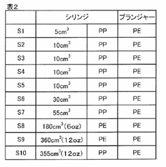
- Table 2 shows the material and volume of the syringe and the material of the plunger.
- Size: 5 cm 3 material: polypropylene (PP), Nordson EFD, product name: Optimum (registered trademark).
- S1 is described as the type of this syringe.
- Size: 10 cm 3 material: polypropylene (PP), Nordson EFD, product name: Optimum (registered trademark).
- S2 is described as the type of this syringe.
- Size: 10 cm 3 material: polypropylene (PP), Musashi Engineering Co., Ltd., product name: PSY-10E.
- S3 is described as the type of this syringe.
- S4 is described as the type of this syringe.
- Size: 10 cm 3 material: polypropylene (PP), Saneitec Co., Ltd., product name: SH11LL-B.
- S5 is described as the type of this syringe.
- Size: 30 cm 3 material: polypropylene (PP), Nordson EFD, product name: Optimum (registered trademark).
- S6 is described as the type of this syringe.
- Example 1 The resin composition Epo1 shown in Table 1 was mixed and dispersed using a three-roll mill. Then, the resin composition was defoamed using a hard mixer (trade name or model number UVR-10L manufactured by Nippon Sosei Industry Co., Ltd.) at 50 to 150 Pa for the time shown in Table 3. Then, the resin composition filled by pressure filling at a pressure of 0.3 MPa was used at 25° C., rotation 100 rpm, and revolution 1000 rpm by using a centrifuge (manufactured by Nippon Sosei Industry Co., Ltd., trade name UFO-15). The cells were centrifuged for the time shown in Table 3. This produced a resin composition containing small voids.
- a hard mixer trade name or model number UVR-10L manufactured by Nippon Sosei Industry Co., Ltd.
- the plunger 3 was inserted into the syringe 1 so as to come into contact with the resin composition 2 filled in the syringe 1.
- a resin composition-filled syringe was manufactured.
- a tip cap 21 was attached to the reduced-diameter opening 11 at one end of the syringe 1.
- a head cap 22 was attached to the opening 12 at the other end of the syringe which faces the diameter-reduced opening 11.
- the syringe filled with the resin composition of Example 1 was frozen and stored at -40°C for 8 hours.
- the syringe filled with the resin composition of Example 1 after frozen storage was allowed to stand at room temperature (25° C.) for 1 hour. After standing still, the presence or absence of peeling of the resin composition from the syringe was confirmed by the following method. Further, after standing, the presence or absence of discharge shortage of the resin composition discharged from the syringe was confirmed by the following method.
- Example 2 A resin composition-filled syringe was manufactured by the same method as in Example 1 except that syringes having different volumes were used and the filling amount of the resin composition was changed. The resin composition-filled syringe was frozen and stored at -40°C for 8 hours.
- Examples 3 to 10 The time for defoaming with a hard mixer and the time for centrifugation were set to the time shown in Table 3, the amount of the resin composition filled in the syringe was set to the amount shown in Table 3, and the storage temperature A resin composition-filled syringe was manufactured in the same manner as in Example 2 except that the temperature was set to Table 3.
- Examples 11-19 In each example, a resin composition-filled syringe was manufactured by the same method as in Example 2 except that the resin composition shown in Table 4 was used. The syringe filled with the resin composition was stored frozen at ⁇ 40° C. for 8 hours.
- Example 20 A resin composition-filled syringe was manufactured by the same method as in Example 1 except that a resin composition containing an acrylic resin was used as the resin composition before filling the syringe. The syringe filled with the resin composition was stored frozen at ⁇ 40° C. for 8 hours.
- Examples 21-28 As shown in Table 5, a syringe filled with a resin composition was prepared in the same manner as in Example 1 except that the volume and type of the syringe were changed, and the amount of the resin composition filled in the syringe was changed. Was manufactured. The syringe filled with the resin composition was stored frozen at ⁇ 40° C. for 8 hours.
- Comparative Example 1 The resins shown in Table 6 were mixed and dispersed using a three roll mill. Then, this resin was degassed for 30 minutes at 96 Pa using a hard mixer (trade name or model number UVR-10L, manufactured by Nippon Sosei Industry Co., Ltd.). Then, this resin was centrifuged using a centrifuge (manufactured by Nippon Sosei Kogyo Co., Ltd., trade name UFO-15) at 25° C., rotation 100 rpm and revolution 1000 rpm for the time shown in Table 6. This produced the resin composition. The resin composition was filled in the amount shown in Table 6 into a syringe having the material and the volume shown in Table 6 by pressure filling at a pressure of 0.3 MPa.
- the plunger 3 was inserted into the syringe 1 so as to come into contact with the resin composition 2 filled in the syringe 1.
- a resin composition-filled syringe was manufactured.
- a tip cap 21 was attached to the reduced-diameter opening 11 at one end of the syringe 1.
- a head cap 22 was attached to the opening 12 at the other end of the syringe 1 facing the reduced diameter opening.
- the resin composition-filled syringe of Comparative Example 1 was frozen and stored at -40°C for 8 hours.
- the resin composition-filled syringe of Comparative Example 1 after frozen storage was allowed to stand at room temperature (25° C.) for 1 hour. After standing still, the presence or absence of peeling of the resin composition from the syringe was confirmed by the following method. Further, after standing, the presence or absence of discharge shortage of the resin composition discharged from the syringe was confirmed by the following method.
- Comparative example 2 The time for defoaming with a hard mixer and the time for centrifugation were set to the time shown in Table 6, the amount of the resin composition filled in the syringe was set to the amount shown in Table 6, and the storage temperature A resin composition-filled syringe was manufactured in the same manner as in Comparative Example 1 except that the temperature was set to Table 6.
- Comparative Examples 3 to 6 In each Comparative Example, a resin composition-filled syringe was manufactured by the same method as in Comparative Example 1 except that the resin composition shown in Table 6 was used. The syringe filled with the resin composition was stored frozen at ⁇ 40° C. for 8 hours.
- Comparative Example 7 The resins shown in Table 6 were mixed and dispersed using a three roll mill. Thereafter, this resin was degassed with a hard mixer (manufactured by Nippon Sosei Kogyo Co., Ltd., trade name or model number UVR-10L) at 50 to 150 Pa for the time shown in Table 6 to remove voids in the resin. A resin composition excluding all was produced. A resin composition-filled syringe was manufactured by the same method as in Comparative Example 1 except that this resin composition was used. The syringe filled with the resin composition was stored frozen at ⁇ 40° C. for 8 hours.
- a hard mixer manufactured by Nippon Sosei Kogyo Co., Ltd., trade name or model number UVR-10L
- Comparative Example 8 The resins shown in Table 6 were mixed and dispersed using a three roll mill. Thereafter, the resin was degassed with a hard mixer (manufactured by Nippon Sosei Kogyo Co., Ltd., trade name or model number UVR-10L) at 50 to 150 Pa for the time shown in Table 6 to give the maximum diameter of Table 6
- a resin composition-filled syringe was manufactured by the same method as in Comparative Example 1 except that this resin composition was used. The syringe filled with the resin composition was stored frozen at ⁇ 40° C. for 8 hours.
- volume ratio of voids Using an X-ray industrial computer tomography apparatus (manufactured by R-F Co., Ltd., trade name: NAOMi-CT), under a condition of tube voltage: 80 kV and tube current: 3 mA, the inside of the syringe has a resolution of 0.068 mm I scanned it.
- the cross-sectional area of the syringe was larger than the imaging area of the industrial X-ray CT apparatus, one cross section was divided into multiple scans to scan the entire cross section. From the image obtained by scanning (scan image), the diameter of the void contained in the resin composition filled in the syringe was visually measured. The volume of each void was calculated from the measured diameter.
- the volume ratio of voids was calculated by dividing the total value of the volumes of the voids contained in the resin composition filled in the syringe by the volume of the resin composition filled in the syringe. Specifically, the volume ratio of voids was calculated based on the formula (I).
- the maximum diameter of the void contained in the resin composition filled in the syringe was measured based on the scan image measured (acquired) using the industrial X-ray CT apparatus used for measuring the volume ratio of the void.
- the maximum diameter of the void means, for example, the largest linear distance among the linear distances of the maximum lengths of the respective voids, which can be confirmed from the scan image obtained by using the above-described apparatus. With respect to all the voids in the syringe in the scan image, the linear distance of the maximum length was measured, and the largest one was defined as the maximum diameter.
- the linear distance of the maximum length of all the voids in the syringe in the scan image is measured, the total value of the linear distance of the maximum length of each void, the value obtained by dividing by the number of voids, The average diameter of voids was used.
- FIG. 2 is a photograph showing the appearance of the resin composition discharged from the resin composition-filled syringe of Example 1.
- FIG. 3 is a photograph showing the appearance of the resin composition discharged from the resin composition-filled syringe of Comparative Example 1.
- the viscosity of the resin composition at 25° C. is 2. even when the type of resin contained in the resin composition is changed. It is in the range of 5 Pa ⁇ s to 650 Pa ⁇ s, or the TI value of TI1 to T13 is in the range of 0.8 to 3.5, and the volume ratio of voids contained in the resin composition is 1. Within the range of 0 volume ppm to 520 volume ppm, and when the maximum diameter of the void is 2,500 ⁇ m or less, the void contained in the resin composition causes the volume shrinkage of the resin composition during freezing. I was able to suppress it.
- the voids contained in the resin composition If the volume ratio is in the range of 1.0 volume ppm to 520 volume ppm and the maximum diameter of the void is 2,500 ⁇ m or less, the volume of the resin composition at the time of freezing depends on the void contained in the resin composition. The contraction could be suppressed. As a result, it was possible to eliminate the peeling of the resin composition from the inner wall of the syringe. In the resin composition-filled syringes of Examples 21 to 28, it was possible to prevent air that forms large voids that cause discharge shortage from being mixed into the resin composition. This made it possible to eliminate the discharge shortage.
- the volume ratio of voids contained in the resin composition exceeded 520 ppm by volume, and a large volume of voids was the resin composition. It was mixed in the liquid and the discharge was cut off. Further, in the resin composition-filled syringe of Comparative Example 8, the maximum diameter of the voids contained in the resin composition exceeded 2,500 ⁇ m, and discharge shortage occurred. In the resin composition-filled syringes of Comparative Examples 2, 4, and 6, the volume ratio of voids contained in the resin composition was less than 1.0 ppm by volume, and the amount of voids contained in the resin composition was too small. For this reason, it was difficult to suppress the volume change of the resin composition during freezing, and the resin composition peeled from the inner wall of the syringe.
- FIG. 2 shows a continuous trajectory 100 ejected from the resin composition-filled syringe of the example.
- FIG. 3 shows a continuous trajectory 100 ejected from the resin composition-filled syringe of the example.
- FIG. 3 shows an interrupted locus 101 ejected from the resin composition-filled syringe of Comparative Example 1.
- reference numeral 102 indicates discharge shortage.
- the resin composition-filled syringe according to the embodiment of the present disclosure can be suitably used as a syringe filled with a viscous material.
- the viscous material is, for example, a sealant for a mechanical component or an electronic component, an adhesive, an electric/electronic circuit forming paste, and an electronic component mounting solder.
Landscapes
- Chemical & Material Sciences (AREA)
- Health & Medical Sciences (AREA)
- Chemical Kinetics & Catalysis (AREA)
- Medicinal Chemistry (AREA)
- Polymers & Plastics (AREA)
- Organic Chemistry (AREA)
- Engineering & Computer Science (AREA)
- Mechanical Engineering (AREA)
- Compositions Of Macromolecular Compounds (AREA)
- Coating Apparatus (AREA)
- Application Of Or Painting With Fluid Materials (AREA)
- Dental Tools And Instruments Or Auxiliary Dental Instruments (AREA)
Abstract
樹脂組成物充填済みシリンジ及びその保存方法を提供する。これらによれば、シリンジから間欠的に樹脂組成物が吐出される原因となる、空気の混入が抑制される。 樹脂組成物充填済みシリンジは、シリンジと、シリンジ内に充填された樹脂組成物と、プランジャーとを含む。前記樹脂組成物は、ボイドを含有する。前記樹脂組成物の体積に対する前記ボイドの体積比率は、1.0体積ppm~520体積ppmである。前記ボイドの最大径は、2,500μm以下である。
Description
本開示の一態様は、樹脂組成物を充填したシリンジ及びその保存方法に関する。
機械部品又は電子部品のシーラント、接着剤、電気・電子回路形成用ペースト、および、電子部品実装用はんだ等の粘性材料は、対象物の微細な特定部位に供給されるために、シリンジを用いて供給される場合がある。シリンジから供給される粘性材料中に多くの空気が混入すると、シリンジから、間欠的に、粘性材料が吐出される。このことは、対象物に粘性材料が供給されない部分が発生する、という吐出切れの原因となり、接合の不具合等を引き起こす場合がある。
例えば、特許文献1には、樹脂組成物等の粘性材料をシリンジに充填する際に、粘性材料内へのガスの混入を防止する技術が開示されている。
樹脂組成物等の粘性材料は、予めシリンジに充填される場合がある。すなわち、樹脂組成物充填済みのシリンジを、保存又は搬送する場合がある。シリンジに充填された樹脂組成物は、保存時又は搬送時の温度変化により、体積が変化する場合がある。この場合、シリンジに充填された樹脂組成物中に、空気が混入する場合がある。このことは、間欠的な吐出または吐出切れの原因となる。
そこで、本開示における1つの目的は、シリンジから間欠的に樹脂組成物が吐出される原因となる、空気の混入を抑制することの可能な、樹脂組成物充填済みシリンジ及びその保存方法を提供することにある。
前記課題を解決するための手段は、以下の通りである。本開示は、以下の態様を包含する。
本開示の第一の態様にかかる樹脂組成物充填済みシリンジは、シリンジと、シリンジ内に充填された樹脂組成物と、プランジャーとを含み、前記樹脂組成物がボイドを含有し、前記樹脂組成物の体積に対する前記ボイドの体積比率は、1.0体積ppm~520体積ppmであり、前記ボイドの最大径が2,500μm以下である。
本開示の第一の態様にかかる樹脂組成物充填済みシリンジは、シリンジと、シリンジ内に充填された樹脂組成物と、プランジャーとを含み、前記樹脂組成物がボイドを含有し、前記樹脂組成物の体積に対する前記ボイドの体積比率は、1.0体積ppm~520体積ppmであり、前記ボイドの最大径が2,500μm以下である。
本開示の第二の態様にかかる樹脂組成物充填済みシリンジの保存方法は、前記樹脂組成物充填済みシリンジを、-80℃~0℃で保存することを含む。
本開示における上記の態様によれば、シリンジから間欠的に樹脂組成物が吐出される原因となる、空気の混入を抑制することが可能な、樹脂組成物充填済みシリンジ及びその保存方法を、提供することができる。
以下、本開示の一態様に係る樹脂組成物充填済みシリンジ及びその保存方法を、実施形態に基づいて説明する。ただし、以下に示す実施形態は、本開示の技術思想を具体化するための例示である。本開示の技術思想は、以下に示される樹脂組成物充填済みシリンジ及びその保存方法に限定されない。
本開示の第一の実施形態に係る樹脂組成物充填済みシリンジは、シリンジと、シリンジ内に充填された樹脂組成物と、プランジャーとを含む。前記樹脂組成物が、ボイドを含有する。前記樹脂組成物の体積に対する前記ボイドの体積比率は、1.0体積ppm~520体積ppmである。前記ボイドの最大径が、2,500μm以下である。本明細書において、ボイドとは、樹脂組成物中の空間部を意味する。
シリンジに充填された樹脂組成物に含まれるボイドの体積は、X線産業コンピュータ断層撮影装置(以下、「産業用X線CT装置」ともいう。)(例えば、株式会社アールエフ、商品名:NAOMi-CT)を用いて測定されることができる。この測定では、産業用X線CT装置を用いて、シリンジ内部を例えば、撮影分解能0.068mmでスキャンする。これにより、スキャン画像を得る。得られたスキャン画像から、目視にて、シリンジに充填されたボイドの直径を測定する。測定された直径から、各ボイドの体積を算出することができる。シリンジに充填された樹脂組成物に含まれるボイドの体積比率は、以下のように算出されることができる。産業用X線CT装置を用いて測定された各ボイドの体積を合計する。この合計値を、シリンジに充填された樹脂組成物の体積で除算する。具体的には、下記式(I)に基づいて、シリンジに充填された樹脂組成物の体積に対するボイドの体積比率を算出することができる。

シリンジに充填された樹脂組成物に含まれるボイドの最大径は、例えば、前述の産業用X線CT装置を用いたスキャンによって得られた画像から確認できるボイドにおいて、各ボイドの最大長さの直線距離のうち、最も大きな直線距離を意味する。スキャン画像におけるシリンジ中の全てのボイドについて、最大長さの直線距離を測定した。測定された直線距離における最も長い直線距離を、最大径とした。また、スキャン画像におけるシリンジ中の全てのボイドの最大長さの直線距離を測定した。各ボイドの最大長さの直線距離の合計値を、ボイドの個数で除すことによって得られた値を、ボイドの平均径とした。
シリンジに充填された樹脂組成物は、保存又は搬送中に、樹脂組成物の安定性を保つために、0℃以下の温度で冷凍される場合がある。樹脂組成物を冷凍した場合、保存又搬送中の樹脂組成物の反応が抑制される。このため、樹脂組成物を、安定した状態に維持しておくことができる。しかしながら、シリンジに充填された樹脂組成物は、冷凍による温度変化に伴って、体積が収縮する。このため、シリンジの内壁と、冷凍により体積収縮した樹脂組成物との間に、隙間が形成される場合がある。使用時に、シリンジ内の樹脂組成物が解凍されると、解凍に伴って、樹脂組成物の体積が膨張する。冷凍時に体積収縮した樹脂組成物と、シリンジの内壁との間の隙間に存在していた空気が、解凍された樹脂組成物中に混入する。解凍時に、樹脂組成物中に空気が混入されると、この空気が、樹脂組成物をシリンジから吐出する際に、間欠的な吐出または吐出切れの原因となる場合がある。
図1は、本開示の第一の実施形態に係る樹脂組成物充填済みシリンジの概略構成を示す断面図である。図1において、樹脂組成物充填済みシリンジは、シリンジ1と、シリンジ1内に充填された樹脂組成物2と、シリンジ1内に挿入されたプランジャー3とを含む。シリンジ1に充填された樹脂組成物2は、複数のボイド4を含有する。シリンジ1は、その一端に、縮径された開口部11を有する。さらに、シリンジ1は、開口部11に対向する他端に、開口部12を有する。開口部12には、プランジャーロッドが挿入される。開口部12の周囲には、フランジ13が備えられていてもよい。また、縮径された開口部11には、開口部11を閉塞するチップキャップ21が備えられていてもよい。プランジャーロッドが挿入される開口部12には、開口部12を閉塞するヘッドキャップ22が備えられてもよい。
シリンジに充填された樹脂組成物2では、シリンジに充填された樹脂組成物2の体積に対するボイドの体積比率が、1.0体積ppm~520体積ppmでる。樹脂組成物2は、最大径が2,500μm以下の小さいボイド4を含有する。このように、シリンジに充填された樹脂組成物2が、小さいボイド4を含有している。これによって、保存又は搬送時の温度変化による、樹脂組成物の体積変化とシリンジの体積変化との差を、小さくすることができる。したがって、間欠的な吐出又は吐出切れが発生するような大きさの空気が、樹脂組成物に混入することを、抑制することができる。例えば、樹脂組成物充填済みシリンジを、0℃以下の温度で冷凍した場合、樹脂組成物の体積収縮は、シリンジ自体の体積収縮よりも大きい。この場合、樹脂組成物の体積収縮とシリンジの体積収縮との差によって、冷凍された樹脂組成物が、シリンジの内壁から剥離し、樹脂組成物とシリンジの内壁との間に隙間が形成されやすい。シリンジに充填された樹脂組成物2は、体積比率が1.0体積ppm~520体積ppmであり、最大径が2,500μm以下の小さいボイド4を、予め含有することができる。これによって、冷凍時の樹脂組成物の体積収縮を抑制すること、および、シリンジ1の内壁と樹脂組成物との間に隙間が形成されることを、抑制することができる。シリンジ1に充填された樹脂組成物2が、小さいボイド4を予め含有することによって、冷凍時における樹脂組成物2の体積収縮が抑制され、樹脂組成物2とシリンジ内壁との剥離が抑制される。これによって、解凍時の樹脂組成物中に、間欠的な吐出または吐出切れの原因となるような空気の混入を、抑制することができる。
シリンジに充填された樹脂組成物中に含有されたボイドの体積比率は、シリンジに充填された樹脂組成物の体積に対して、より好ましくは1.0体積ppm~510体積ppmであり、さらに好ましくは1.0体積ppm~505体積ppmである。樹脂組成物中に含有されたボイドの体積比率が、シリンジ内に充填された樹脂組成物の体積に対して1.0体積ppm未満である場合、樹脂組成物に予め含有されたボイドの体積比率が少なすぎる。このため、冷凍時の樹脂組成物の体積収縮を抑制することが困難となる。したがって、収縮した樹脂組成物のシリンジの内壁からの剥離を抑制することが困難となる。樹脂組成物中に含有されたボイドの体積比率が、シリンジ内に充填された樹脂組成物の体積に対して520体積ppmを超える場合、混入されるボイドのサイズが大きくなる場合がある。このため、シリンジから樹脂組成物が吐出される際に、吐出切れの不具体が生じる場合がある。
シリンジに充填された樹脂組成物に含有されたボイドの最大径が、2,500μm以下である場合、温度変化に伴う樹脂組成物の体積変化を抑制することができる。これにより、温度変化に伴う樹脂組成物の体積変化とシリンジの体積変化との差を小さくすること可能となる。したがって、間欠的な吐出又は吐出切れを発生させるような、大きなボイドとなる空気の混入を、抑制することができる。シリンジに充填される樹脂組成物に含有されたボイドの最大径は、より好ましくは2,400μm以下であり、さらに好ましくは2,300μm以下であり、よりさらに好ましくは2,200μm以下である。シリンジに充填される樹脂組成物に含有されたボイドの最大径の下限値は、特に制限されない。シリンジに充填される樹脂組成物に含有されたボイドの最大径は、一般的に100μm以上である。
シリンジに充填された樹脂組成物に含まれるボイドに関し、ボイドの体積比率が1.0体積ppm~520体積ppmであり、ボイドの最大径が2,500μm以下である場合には、ボイドの平均径は、200μm~400μmであってもよく、250μm~350μmであってもよい。シリンジに充填された樹脂組成物に含まれるボイドの平均径が、200μm~400μmである場合、温度変化に伴う樹脂組成物の体積変化を抑制することができる。これにより、温度変化に伴う樹脂組成物の体積変化とシリンジの体積変化との差を小さくすることが可能となる。したがって、間欠的な吐出又は吐出切れを発生させるような、大きなボイドとなる空気の混入を、抑制することができる。
シリンジに充填される樹脂組成物に、最大径が2,500μm以下となるような小さいボイドを予め含有させる方法について説明する。例えば、樹脂組成物を、3本ロールミルを用いて、300gバッチで20分混練しすることにより、樹脂組成物にボイドを含有させることができる。その後、ハードミキサーによって、樹脂組成物から大きなボイドを脱泡する。さらに、遠心機(例えば、日本ソセー工業株式会社製、商品名UFO-15)を用いて、自転100rpm、公転1000rpmで、所定の時間、樹脂組成物を遠心分離する。これにより、間欠的な吐出又は吐出切れを発生させるような大きなボイドを、樹脂組成物から脱泡することができる。その結果、シリンジに充填される樹脂組成物の体積に対するボイドの体積比率が、1.0体積ppm~520体積ppmとなる。したがって、最大径が2,500μm以下となる小さいボイドを、樹脂組成物に含有させることができる。また、シリンジに充填される樹脂組成物に小さいボイドを予め含有させる別の方法では、例えば、樹脂組成物を、ハ-ドミキサー(例えば、日本ソセー工業株式会社製、商品名UV10L)を用いて、50~150Pa、40rpmで、任意の時間、撹拌する。これにより、間欠的な吐出又は吐出切れを発生させるような大きなボイドを、樹脂組成物から脱泡する。その結果、シリンジに充填される樹脂組成物の体積に対するボイドの体積比率が、1.0体積ppm~520体積ppmとなる。したがって、最大径が2,500μm以下となる小さいボイドを、樹脂組成物に含有させることができる。
シリンジに充填される樹脂組成物は、エポキシ樹脂及びアクリル樹脂から選ばれる少なくとも1種の樹脂を含むことが好ましい。エポキシ樹脂及びアクリル樹脂から選ばれる少なくとも1種の樹脂は、機械部品又は電子部品のシーラント、接着剤、および、電気・電子回路形成用ペースト等の材料として、用いられる。
エポキシ樹脂は、常温で液状であるものが好ましいが、常温で固体のものであってもよい。常温で固体のエポキシ樹脂は、液状のエポキシ樹脂、溶剤又は希釈剤により希釈されることにより、液状にされて用いられることができる。エポキシ樹脂は、分子内に少なくとも1つのエポキシ基又はグリシジル基を有するものを味する。エポキシ樹脂としては、例えば、ビスフェノールA型エポキシ樹脂、ビスフェノールF型エポキシ樹脂及びこれらの誘導体(例えば、アルキレンオキシド付加物)、水素添加ビスフェノールA型エポキシ樹脂、水素添加ビスフェノールF型エポキシ樹脂、臭素化ビスフェノールA型エポキシ樹脂、ビフェニル型エポキシ樹脂、ナフタレン型エポキシ樹脂、炭素数が6~36のアルキルグリシジルエーテル、アルキルフェニルグリシジルエーテル、アルケニルグリシジルエーテル、アルキニルグリシジルエーテル、フェニルグリシジルエーテル等のグリシジルエーテル型エポキシ樹脂、炭素数が6~36のアルキルグリシジルエステル、アルケニルグリシジルエステル、フェニルグリシジルエステル等のグリシジルエステル型エポキシ樹脂、および、シリコーンエポキシ樹脂が挙げられる。これらのエポキシ樹脂については、一種が単独で使用されてもよく、二種以上が併用されてもよい。
アクリル樹脂は、(メタ)アクリル樹脂であることが好ましく、分子内に(メタ)アクリロイル基を有する化合物を意味する。(メタ)アクリル樹脂としては、例えば、メチル(メタ)アクリレート、エチル(メタ)アクリレート、n-ブチル(メタ)アクリレート、イソブチル(メタ)アクリレート、タ―シャルブチル(メタ)アクリレート、イソデシル(メタ)アクリレート、ラウリル(メタ)アクリレート、トリデシル(メタ)アクリレート、セチル(メタ)アクリレート、ステアリル(メタ)アクリレート、イソアミル(メタ)アクリレート、イソステアリル(メタ)アクリレート、ベヘニル(メタ)アクリレート、2-エチルヘキシル(メタ)アクリレート、その他のアルキル(メタ)アクリレート、シクロヘキシル(メタ)アクリレート、ターシャルブチルシクロヘキシル(メタ)アクリレート、テトラヒドロフルフリル(メタ)アクリレート、ベンジル(メタ)アクリレート、フェノキシエチル(メタ)アクリレート、イソボルニル(メタ)アクリレート、グリシジル(メタ)アクリレート、トリメチロールプロパントリ(メタ)アクリレート、ジンクモノ(メタ)アクリレート、ジンクジ(メタ)アクリレート、ジメチルアミノエチル(メタ)アクリレート、ジエチルアミノエチル(メタ)アクリレート、ネオペンチルグリコール(メタ)アクリレート、トリフロロエチル(メタ)アクリレート、2,2,3,3-テトラフロロプロピル(メタ)アクリレート、2,2,3,3,4,4-ヘキサフロロブチル(メタ)アクリレート、パーフロロオクチル(メタ)アクリレート、パーフロロオクチルエチル(メタ)アクリレート、エチレングリコールジ(メタ)アクリレート、プロピレングリコールジ(メタ)アクリレート、1,4-ブタンジオールジ(メタ)アクリレート、1,6-ヘキサンジオールジ(メタ)アクリレート、1,9-ノナンジオールジ(メタ)アクリレート、1,3-ブタンジオールジ(メタ)アクリレート、1,10-デカンジオールジ(メタ)アクリレート、テトラメチレングリコールジ(メタ)アクリレート、メトキシエチル(メタ)アクリレート、ブトキシエチル(メタ)アクリレート、エトキシジエチレングリコール(メタ)アクリレート、メトキシポリアルキレングリコールモノ(メタ)アクリレート、オクトキシポリアルキレングリコールモノ(メタ)アクリレート、ラウロキシポリアルキレングリコールモノ(メタ)アクリレート、ステアロキシポリアルキレングリコールモノ(メタ)アクリレート、アリロキシポリアルキレングリコールモノ(メタ)アクリレート、ノニルフェノキシポリアルキレングリコールモノ(メタ)アクリレート、ジ(メタ)アクリロイルオキシメチルトリシクロデカン、N-(メタ)アクリロイルオキシエチルマレイミド、N-(メタ)アクリロイルオキシエチルヘキサヒドロフタルイミド、および、N-(メタ)アクリロイルオキシエチルフタルイミドが挙げられる。さらに、(メタ)アクリル樹脂として、たとえば、(メタ)アクリルアミドが挙げられる。(メタ)アクリルアミドは、たとえば、N,N’-メチレンビス(メタ)アクリルアミド、N,N’-エチレンビス(メタ)アクリルアミド、および、1,2-ジ(メタ)アクリルアミドエチレングリコールを含む。これらのアクリル樹脂は、一種が単独で使用されてもよく、二種以上が併用されてもよい。
また、アクリル樹脂として、ポリ(メタ)アクリレート等が挙げられる。ポリ(メタ)アクリレートとしては、(メタ)アクリル酸と(メタ)アクリレートとの共重合体、又は、水酸基を有する(メタ)アクリレートと極性基を有さない(メタ)アクリレートとの共重合体等が挙げられる。アクリル樹脂としては、例えば、水酸基を有する(メタ)アクリレートが挙げられる。水酸基を有する(メタ)アクリレートとしては、たとえば、2-ヒドロキシエチル(メタ)アクリレート、2-ヒドロキシプロピル(メタ)アクリレート、3-ヒドロキシプロピル(メタ)アクリレート、2-ヒドロキシブチル(メタ)アクリレート、3-ヒドロキシブチル(メタ)アクリレート、4-ヒドロキシブチル(メタ)アクリレート、1,2-シクロヘキサンジオールモノ(メタ)アクリレート、1,3-シクロヘキサンジオールモノ(メタ)アクリレート、1,4-シクロヘキサンジオールモノ(メタ)アクリレート、1,2-シクロヘキサンジメタノールモノ(メタ)アクリレート、1,3-シクロヘキサンジメタノールモノ(メタ)アクリレート、1,4-シクロヘキサンジメタノールモノ(メタ)アクリレート、1,2-シクロヘキサンジエタノールモノ(メタ)アクリレート、1,3-シクロヘキサンジエタノールモノ(メタ)アクリレート、1,4-シクロヘキサンジエタノールモノ(メタ)アクリレート、グリセリンモノ(メタ)アクリレート、グリセリンジ(メタ)アクリレート、トリメチロールプロパンモノ(メタ)アクリレート、トリメチロールプロパンジ(メタ)アクリレート、ペンタエリスリトールモノ(メタ)アクリレート、ペンタエリスリトールジ(メタ)アクリレート、ペンタエリスリトールトリ(メタ)アクリレート、および、ネオペンチルグリコールモノ(メタ)アクリレートが挙げられる。または、アクリル樹脂として、たとえば、上記した水酸基を有する(メタ)アクリレートと、ジカルボン酸又はその誘導体とを反応させることによって得られる、カルボキシ基を有する(メタ)アクリレートが挙げられる。ここで使用可能なジカルボン酸としては、例えば、シュウ酸、マロン酸、コハク酸、グルタル酸、アジピン酸、ピメリン酸、スベリン酸、アゼライン酸、セバシン酸、マレイン酸、フマル酸、フタル酸、テトラヒドロフタル酸、ヘキサヒドロフタル酸、及び、これらの誘導体が挙げられる。これらのアクリル樹脂は、一種が単独で使用されてもよく、二種以上が併用されてもよい。
シリンジに充填される樹脂組成物は、エポキシ樹脂及びアクリル樹脂から選ばれる少なくとも1種の樹脂の他に、フィラー、硬化剤、溶剤、反応性希釈剤、エラストマー、カップリング剤、フラックス剤、消泡剤、表面調整剤、レオロジー調整剤、着色剤、可塑剤、又は分散剤からなる群から選ばれる少なくとも1種のものを含んでいてもよい。
シリンジに充填される樹脂組成物における200Pa・s未満の粘度を、回転粘度計を用いて、25℃で、50rpmの回転数で測定した結果が、2.5Pa・s~650Pa・sであることが好ましい。さらに、シリンジに充填される樹脂組成物における200Pa・s以上の粘度を、回転粘度計を用いて、25℃で、10rpmの回転数で測定した結果が、2.5Pa・s~650Pa・sであることが好ましい。シリンジに充填される樹脂組成物の粘度が、2.5Pa・s~650Pa・sである場合、前述の方法によって、樹脂組成物の体積に対するボイドの体積比率が1.0体積ppm~520体積ppmとなり、ボイドの最大径が2,500μm以下となるように、樹脂組成物をシリンジに充填することができる。
より具体的には、シリンジに充填される樹脂組成物の粘度は、25℃における粘度が2.5Pa・s以上20Pa・s未満の範囲内の場合には、例えば回転粘度計RV型(スピンドルSC-14)(ブルックフィールド社製)を用いて、50rpmで、測定されることができる。また、シリンジに充填される樹脂組成物の粘度は、25℃における粘度が20Pa・s以上200Pa・s未満の範囲内の場合には、例えば回転粘度計HBDV-1(スピンドルSC4-14)(ブルックフィールド社製)を用いて、50rpmで、測定されることができる。また、シリンジに充填される樹脂組成物の粘度は、25℃における粘度が200Pa・s以上1,000Pa・s以下の範囲内の場合には、例えば回転粘度計HBDV-1(スピンドルSC4-14)(ブルックフィールド社製)を用いて、10rpmで、測定されることができる。
シリンジに充填される樹脂組成物では、以下(1)から(3)の条件で測定されるチキソトロピーインデックスTI1~TI3が、0.8~3.5であることが好ましい。
(1)回転粘度計(例えばRV型(スピンドルSC-14)、ブルックフィールド社製)を用いて25℃で測定された50rpmの粘度が、2.5Pa・s以上20Pa・s未満の範囲内であり、5rpmの粘度と50rpmの粘度との比率である、チキソトロピーインデックスTI1。
(2)回転粘度計(例えば回転粘度計HBDV-1(スピンドルSC4-14)、ブルックフィールド社製)を用いて25℃で測定された50rpmの粘度が、20Pa・s以上200Pa・s未満の範囲内であり、5rpmの粘度と50rpmnの粘度の比率である、チキソトロピーインデックスTI2。
(3)回転粘度計(例えば回転粘度計HBDV-1(スピンドルSC4-14)、ブルックフィールド社製)を用いて25℃で測定された10rpmの粘度が、200Pa・s以上1,000Pa・s以下の範囲内であり、1rpmの粘度と10rpmの粘度の比率である、チキソトロピーインデックスTI3。
(1)回転粘度計(例えばRV型(スピンドルSC-14)、ブルックフィールド社製)を用いて25℃で測定された50rpmの粘度が、2.5Pa・s以上20Pa・s未満の範囲内であり、5rpmの粘度と50rpmの粘度との比率である、チキソトロピーインデックスTI1。
(2)回転粘度計(例えば回転粘度計HBDV-1(スピンドルSC4-14)、ブルックフィールド社製)を用いて25℃で測定された50rpmの粘度が、20Pa・s以上200Pa・s未満の範囲内であり、5rpmの粘度と50rpmnの粘度の比率である、チキソトロピーインデックスTI2。
(3)回転粘度計(例えば回転粘度計HBDV-1(スピンドルSC4-14)、ブルックフィールド社製)を用いて25℃で測定された10rpmの粘度が、200Pa・s以上1,000Pa・s以下の範囲内であり、1rpmの粘度と10rpmの粘度の比率である、チキソトロピーインデックスTI3。
前記(1)の条件で測定されたチキソトロピーインデックスTI1は、回転粘度計RV型(スピンドルSC-14)(ブルックフィールド社製)を用いて25℃で測定された、5rpmの粘度V15rpmと、50rpmの粘度V150rpmとの比率であり、以下の式(II)に基づいて、求められる。

前記(2)の条件で測定されたチキソトロピーインデックスTI2は、回転粘度計HBDV-1(スピンドルSC-14)(ブルックフィールド社製)を用いて25℃で測定された、5rpmの粘度V25rpmと、50rpmの粘度V250rpmとの比率であり、以下の式(III)に基づいて、求められる。

前記(3)の条件で測定されたチキソトロピーインデックスTI3は、回転粘度計HBDV-1(スピンドルSC-14)(ブルックフィールド社製)を用いて25℃で測定された、1rpmの粘度V31rpmと、10rpmの粘度V310rpmとの比率であり、以下の式(III)に基づいて、求められる。

樹脂組成物の粘度に対応した測定条件で測定されるチキソトロピーインデックスTI1~TI3を、TI値とも称する。TI値は、粘度のせん断速度(粘度計の回転数)に対する依存性として測定される、チキソトロピー性を表す指標である。せん断速度が変わっても粘度が変化しない、水のようなニュートン流体のTI値は、1である。TI値が1よりも小さいことは、せん断力が小さい場合の方が、せん断力が大きい場合に比べて、粘度が小さいことを示す。TI値が1よりも大きいことは、せん断力が小さい場合の方が、せん断力が大きい場合に比べて、粘度が大きいことを示す。TI値が大きいほど、チキソトロピー性が高くなる。
シリンジに充填される樹脂組成物が、25℃において50rpmで測定される粘度が200Pa・s未満の、低粘度である場合、又は、25℃において10rpmで測定される粘度が200Pa・s以上1,000Pa・sの、高粘度である場合には、チキソトロピーインデックスTI1~T13が、0.8~3.5の範囲内であることが好ましい。チキソトロピーインデックスTI1~TI3が、0.8~3.5の範囲内であると、シリンジに充填される樹脂組成物中に混入された小さいボイドの分散性がよくなる。したがって、シリンジから樹脂組成物を吐出させる際の作業性が良くなる。シリンジに充填される樹脂組成物は、チキソトロピーインデックスが0.8~1.2の、ニュートン流体に近いチキソトロピー性を有するものであってもい。あるいは、シリンジに充填される樹脂組成物は、チキソトロピーインデックスが1.2を超える、非ニュートン流体のチキソトロピー性を有するものであってもよい。
シリンジとしては、ポリプロピレン製、ポリエチレン製、ポリスチレン製、およびポリエステル製等のものが挙げられる。特に、シリンジは、ポリプロピレン製又はポリエチレン製であることが好ましい。これにより、シリンジに充填された樹脂組成物に含有されるボイドによって、温度変化に伴う樹脂組成物の体積変化とシリンジの体積変化との差を、容易に小さくすることができる。また、ポリプロピレンおよびポリエチレンは安価であるために、シリンジのコストを抑えることができる。
シリンジの容積は、1cm3~600cm3であることが好ましい。ここで、シリンジの容積は、シリンジ内部の容積を意味する。シリンジの容積は、より好ましくは3cm3~500cm3であり、さらに好ましくは3cm3~360cm3である。シリンジの容積が1cm3~600cm3であると、シリンジに充填される樹脂組成物に小さいボイドを予め含有させておくことによって、温度変化に伴う樹脂組成物の体積変化を抑制することができる。これにより、温度変化に伴う樹脂組成物の体積変化とシリンジの体積変化との差を小さくすることが可能となる。したがって、間欠的な吐出又は吐出切れを発生させるような、大きなボイドとなる空気の混入を、抑制することができる。シリンジとしては、例えば、1cm3、2cm3、3cm3、5cm3、10cm3、30cm3、55cm3、180cm3、360cm3、あるいは600cm3の容積を有するシリンジが挙げられる。
プランジャーを構成する材料は、特に制限されない。プランジャーを構成する材料としては、例えば、各種ゴム材料、および、熱可塑性エラストマー等の弾性材料が挙げられる。各種ゴム材料は、たとえば、天然ゴム、ブチルゴム、イソプレンゴム、ブタジエンゴム、スチレン-ブタジエンゴム、および、シリコーンゴムを含む。熱可塑性エラストマーは、たとえば、ポリエチレン、ポリウレタン、ポリエステル、およびポリアミドを含む。プランジャーの形態については、プランジャーの少なくとも一方の端部が、円錐形となっていてもよく、プランジャーの少なくとも一方の端部が、平坦な形態となっていてもよい。
樹脂組成物充填済みシリンジの製造方法は、例えば、上述の方法によって、最大径が2,500μm以下の小さいボイドを、樹脂組成物に予め含有させること、この樹脂組成物を、0.1MPaを超えて0.6MPa以下の圧力で、加圧充填の方法により、シリンジに充填すること、および、充填された樹脂組成物に密着するように、プランジャーをシリンジ内に挿入すること、を含む。樹脂充填済みのシリンジについては、図1に示すように、シリンジの縮径された開口部11に、チップキャップ21が装着されてもよく、フランジを備えた開口部12に、ヘッドキャップ22が装着されてもよい。
樹脂組成物充填済みのシリンジは、-80℃~0℃の温度で保存されることが好ましい。樹脂組成物充填済みシリンジの保存方法について、樹脂組成物充填済みシリンジを、-80℃~0℃で冷凍保存することにより、シリンジに内に充填された樹脂組成物の反応が抑制される。このため、樹脂組成物を、安定した状態で保存しておくことができる。樹脂組成物充填済みのシリンジは、-80℃~-10℃で保存されることが好ましく、-80℃~-20℃で保存されることがさらに好ましい。樹脂組成物充填済みシリンジでは、低温での保存により体積変化が大きくなった場合であっても、樹脂組成物に含有された小さいボイドによって、樹脂組成物の体積変化を抑制することができる。これにより、樹脂組成物の体積変化とシリンジの体積変化との差を小さくすることが可能となる。したがって、シリンジから樹脂組成物を吐出させる際に、間欠的な吐出又は吐出切れが発生するような大きさの空気の混入を、抑制することができる。
以下、本開示の実施形態を、実施例を用いて、より具体的に説明する。ただし、本開示の技術は、これらの実施例に限定されない。
表1に示す配合割合となるように、実施例及び比較例に用いられる樹脂組成物EPO1からEPO6及びACR1を製造した。下記の各原料を、3本ロールミルを用いて混錬することにより、樹脂組成物を調製した。なお、表中の各組成に関する数値は、質量部を表す。
A:ビスフェノールF型エポキシ樹脂、製品名YDF8170、新日鐵化学株式会社製、エポキシ当量158g/eq。
B:アミン硬化剤:4,4’-ジアミノ-3,3’-ジエチルジフェニルメタン、製品名カヤハードA-A(HDAA)、日本化薬株式会社製。
C:トリシクロデカンジメタノールジアクリレート、製品名A-DCP、新中村工業株式会社製。
D:重合開始剤、t-ブチル-α-クミルパーオキサイド、製品名Perbutyl C、日油株式会社製。
E-1:無機充填材、高純度合成球状シリカ(シランカップリング剤(3-グリシドキシプロピルトリメトキシシラン)表面処理シリカフィラー)(平均粒径0.6μm)、製品名SE2200-SEE、株式会社アドマテックス製。
E-2:無機充填材、疎水性フュームドシリカ(平均粒径20nm)、製品名R805、日本アエロジル株式会社製。
A:ビスフェノールF型エポキシ樹脂、製品名YDF8170、新日鐵化学株式会社製、エポキシ当量158g/eq。
B:アミン硬化剤:4,4’-ジアミノ-3,3’-ジエチルジフェニルメタン、製品名カヤハードA-A(HDAA)、日本化薬株式会社製。
C:トリシクロデカンジメタノールジアクリレート、製品名A-DCP、新中村工業株式会社製。
D:重合開始剤、t-ブチル-α-クミルパーオキサイド、製品名Perbutyl C、日油株式会社製。
E-1:無機充填材、高純度合成球状シリカ(シランカップリング剤(3-グリシドキシプロピルトリメトキシシラン)表面処理シリカフィラー)(平均粒径0.6μm)、製品名SE2200-SEE、株式会社アドマテックス製。
E-2:無機充填材、疎水性フュームドシリカ(平均粒径20nm)、製品名R805、日本アエロジル株式会社製。
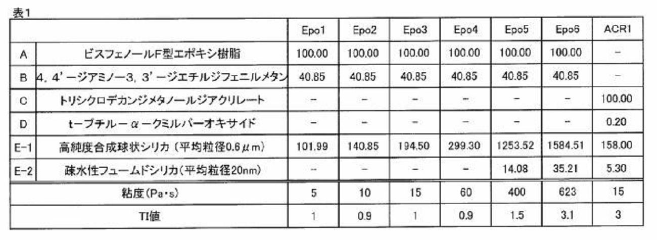
製造された樹脂組成物について、以下の条件で、粘度(Pa・s)、および、チキソトロピーインデックスを測定した。測定結果を表1に示す。なお、表1及び表4~6において、樹脂組成物の粘度に対応した条件で測定されたTI1~TI3は、TI値として記載されている。
(1)25℃における粘度が2.5Pa・s以上20Pa・s未満の範囲内の場合には、回転粘度計RV型(スピンドルSC-14)(ブルックフィールド社製)を用いて、50rpmで、粘度を測定した。さらに、前記式(II)に基づいて、チキソトロピーインデックスTI1を測定した。
(2)25℃における粘度が20Pa・s以上200Pa・s未満の範囲内の場合には、回転粘度計HBDV-1(スピンドルSC4-14)(ブルックフィールド社製)を用いて、50rpmで、粘度を測定した。さらに、前記式(III1)に基づいて、チキソトロピーインデックスTI2を測定した。
(3)25℃における粘度が200Pa・s以上1,000Pa・s以下の範囲内の場合には、回転粘度計HBDV-1(スピンドルSC4-14)(ブルックフィールド社製)を用いて、10rpmで、粘度を測定した。さらに、前記式(IV)に基づいて、チキソトロピーインデックスTI3を測定した。
(1)25℃における粘度が2.5Pa・s以上20Pa・s未満の範囲内の場合には、回転粘度計RV型(スピンドルSC-14)(ブルックフィールド社製)を用いて、50rpmで、粘度を測定した。さらに、前記式(II)に基づいて、チキソトロピーインデックスTI1を測定した。
(2)25℃における粘度が20Pa・s以上200Pa・s未満の範囲内の場合には、回転粘度計HBDV-1(スピンドルSC4-14)(ブルックフィールド社製)を用いて、50rpmで、粘度を測定した。さらに、前記式(III1)に基づいて、チキソトロピーインデックスTI2を測定した。
(3)25℃における粘度が200Pa・s以上1,000Pa・s以下の範囲内の場合には、回転粘度計HBDV-1(スピンドルSC4-14)(ブルックフィールド社製)を用いて、10rpmで、粘度を測定した。さらに、前記式(IV)に基づいて、チキソトロピーインデックスTI3を測定した。
実施例及び比較例に用いられたシリンジの種類を、以下の(1)~(10)に示す。さらに、シリンジの材質および容積、ならびに、プランジャーの材質を、表2に記載した。
(1)サイズ:5cm3、材質:ポリプロピレン(PP)製、ノードソンEFD社製、製品名:Optimum(登録商標)。表中、このシリンジの種別として、S1と記載する。
(2)サイズ:10cm3、材質:ポリプロピレン(PP)製、ノードソンEFD社製、製品名:Optimum(登録商標)。表中、このシリンジの種別として、S2と記載する。
(3)サイズ:10cm3、材質:ポリプロピレン(PP)製、武蔵エンジニアリング株式会社製、製品名:PSY-10E。表中、このシリンジの種別として、S3と記載する。
(4)サイズ:10cm3、材質:ポリプロピレン(PP)製、岩下エンジニアリング株式会社製、製品名:PS10S。表中、このシリンジの種別として、S4と記載する。
(5)サイズ:10cm3、材質:ポリプロピレン(PP)製、株式会社サンエイテック、製品名:SH11LL-B。表中、このシリンジの種別として、S5と記載する。
(6)サイズ:30cm3、材質:ポリプロピレン(PP)製、ノードソンEFD社製、製品名:Optimum(登録商標)。表中、このシリンジの種別として、S6と記載する。
(7)サイズ:55cm3、材質:ポリプロピレン(PP)製、ノードソンEFD社製、製品名:Optimum(登録商標)。表中、このシリンジの種別として、S7と記載する。
(8)サイズ:180cm3(6ounce、6oz)、材質:ポリエチレン(PE)製、ノードソンEFD社製、製品名:Optimum(登録商標)。表中、このシリンジの種別として、S8と記載する。
(9)サイズ:360cm3(12ounce、12oz)、材質:ポリエチレン(PE)製、ノードソンEFD社製、製品名:Optimum(登録商標)。表中、このシリンジの種別として、S9と記載する。
(10)サイズ:355cm3(12oz)、材質:ポリプロピレン(PP)製、SEMCO社製、製品名SEMCO 120ounce cartidge。表中、このシリンジの種別として、S10と記載する。
(1)サイズ:5cm3、材質:ポリプロピレン(PP)製、ノードソンEFD社製、製品名:Optimum(登録商標)。表中、このシリンジの種別として、S1と記載する。
(2)サイズ:10cm3、材質:ポリプロピレン(PP)製、ノードソンEFD社製、製品名:Optimum(登録商標)。表中、このシリンジの種別として、S2と記載する。
(3)サイズ:10cm3、材質:ポリプロピレン(PP)製、武蔵エンジニアリング株式会社製、製品名:PSY-10E。表中、このシリンジの種別として、S3と記載する。
(4)サイズ:10cm3、材質:ポリプロピレン(PP)製、岩下エンジニアリング株式会社製、製品名:PS10S。表中、このシリンジの種別として、S4と記載する。
(5)サイズ:10cm3、材質:ポリプロピレン(PP)製、株式会社サンエイテック、製品名:SH11LL-B。表中、このシリンジの種別として、S5と記載する。
(6)サイズ:30cm3、材質:ポリプロピレン(PP)製、ノードソンEFD社製、製品名:Optimum(登録商標)。表中、このシリンジの種別として、S6と記載する。
(7)サイズ:55cm3、材質:ポリプロピレン(PP)製、ノードソンEFD社製、製品名:Optimum(登録商標)。表中、このシリンジの種別として、S7と記載する。
(8)サイズ:180cm3(6ounce、6oz)、材質:ポリエチレン(PE)製、ノードソンEFD社製、製品名:Optimum(登録商標)。表中、このシリンジの種別として、S8と記載する。
(9)サイズ:360cm3(12ounce、12oz)、材質:ポリエチレン(PE)製、ノードソンEFD社製、製品名:Optimum(登録商標)。表中、このシリンジの種別として、S9と記載する。
(10)サイズ:355cm3(12oz)、材質:ポリプロピレン(PP)製、SEMCO社製、製品名SEMCO 120ounce cartidge。表中、このシリンジの種別として、S10と記載する。
実施例1
表1に示す樹脂組成物Epo1を、3本ロールミルを使用して混合及び分散させた。その後、この樹脂組成物を、ハードミキサー(日本ソセー工業株式会社製、商品名又は型番UVR-10L)を用いて、50~150Paで、表3に示す時間、脱泡した。その後、0.3MPaの圧力で、加圧充填により充填された樹脂組成物を、遠心機(日本ソセー工業株式会社製、商品名UFO-15)を用いて、25℃、自転100rpm、公転1000rpmで、表3に示す時間、遠心分離した。これにより、小さいボイドを含有した樹脂組成物が製造された。シリンジ1に充填された樹脂組成物2に接触するように、シリンジ1内にプランジャー3を挿入した。これにより、樹脂組成物充填済みシリンジが製造された。シリンジ1の一端の縮径された開口部11には、チップキャップ21を装着した。さらに、縮径された開口部11に対向するシリンジの他端の開口部12には、ヘッドキャップ22を装着した。樹脂組成物の充填後、冷凍保存する前に、シリンジに充填された樹脂組成物中のボイドの最大径、および、シリンジに充填された樹脂組成物の体積に対するボイドの体積比率を、下記に示す方法により測定した。測定結果を表3に示す。
表1に示す樹脂組成物Epo1を、3本ロールミルを使用して混合及び分散させた。その後、この樹脂組成物を、ハードミキサー(日本ソセー工業株式会社製、商品名又は型番UVR-10L)を用いて、50~150Paで、表3に示す時間、脱泡した。その後、0.3MPaの圧力で、加圧充填により充填された樹脂組成物を、遠心機(日本ソセー工業株式会社製、商品名UFO-15)を用いて、25℃、自転100rpm、公転1000rpmで、表3に示す時間、遠心分離した。これにより、小さいボイドを含有した樹脂組成物が製造された。シリンジ1に充填された樹脂組成物2に接触するように、シリンジ1内にプランジャー3を挿入した。これにより、樹脂組成物充填済みシリンジが製造された。シリンジ1の一端の縮径された開口部11には、チップキャップ21を装着した。さらに、縮径された開口部11に対向するシリンジの他端の開口部12には、ヘッドキャップ22を装着した。樹脂組成物の充填後、冷凍保存する前に、シリンジに充填された樹脂組成物中のボイドの最大径、および、シリンジに充填された樹脂組成物の体積に対するボイドの体積比率を、下記に示す方法により測定した。測定結果を表3に示す。
実施例1の樹脂組成物充填済みシリンジを、-40℃、8時間、冷凍保存した。冷凍保存後の実施例1の樹脂組成物充填済みシリンジを、室温(25℃)で、1時間、静置した。静置した後に、以下の方法で、樹脂組成物のシリンジからの剥離の有無を確認した。また、静置後、以下の方法で、シリンジから吐出された樹脂組成物の吐出切れの有無を確認した。
実施例2
容積の異なるシリンジを用いたこと、及び、樹脂組成物の充填量を変えたこと以外は、実施例1と同様の方法により、樹脂組成物充填済みシリンジを製造した。樹脂組成物充填済みシリンジを、-40℃、8時間、冷凍保存した。
容積の異なるシリンジを用いたこと、及び、樹脂組成物の充填量を変えたこと以外は、実施例1と同様の方法により、樹脂組成物充填済みシリンジを製造した。樹脂組成物充填済みシリンジを、-40℃、8時間、冷凍保存した。
実施例3~10
ハードミキサーで脱泡する時間、および、遠心分離をする時間を、表3に示す時間としたこと、シリンジに充填する樹脂組成物の量を、表3に示す量としたこと、および、保存温度を表3に示す温度としたこと以外は、実施例2と同様の方法により、樹脂組成物充填済みシリンジを製造した。
ハードミキサーで脱泡する時間、および、遠心分離をする時間を、表3に示す時間としたこと、シリンジに充填する樹脂組成物の量を、表3に示す量としたこと、および、保存温度を表3に示す温度としたこと以外は、実施例2と同様の方法により、樹脂組成物充填済みシリンジを製造した。
実施例11~19
各実施例において、表4に示す樹脂組成物を用いたこと以外は、実施例2と同様の方法により、樹脂組成物充填済みシリンジを製造した。樹脂組成物充填済みシリンジを、-40℃、8時間冷凍保存した。
各実施例において、表4に示す樹脂組成物を用いたこと以外は、実施例2と同様の方法により、樹脂組成物充填済みシリンジを製造した。樹脂組成物充填済みシリンジを、-40℃、8時間冷凍保存した。
実施例20
シリンジに充填する前の樹脂組成物として、アクリル樹脂を含む樹脂組成物を用いたこと以外は、実施例1と同様の方法により、樹脂組成物充填済みシリンジを製造した。樹脂組成物充填済みシリンジを、-40℃、8時間冷凍保存した。
シリンジに充填する前の樹脂組成物として、アクリル樹脂を含む樹脂組成物を用いたこと以外は、実施例1と同様の方法により、樹脂組成物充填済みシリンジを製造した。樹脂組成物充填済みシリンジを、-40℃、8時間冷凍保存した。
実施例21~28
表5に示すように、シリンジの容積および種別を変更したこと、および、シリンジに充填する樹脂組成物の量を変更したこと以外は、実施例1と同様の方法により、樹脂組成物充填済みシリンジを製造した。樹脂組成物充填済みシリンジを、-40℃、8時間冷凍保存した。
表5に示すように、シリンジの容積および種別を変更したこと、および、シリンジに充填する樹脂組成物の量を変更したこと以外は、実施例1と同様の方法により、樹脂組成物充填済みシリンジを製造した。樹脂組成物充填済みシリンジを、-40℃、8時間冷凍保存した。
比較例1
表6に示す樹脂を、3本ロールミルを使用して混合及び分散させた。その後、この樹脂を、ハードミキサー(日本ソセー工業社製、商品名又は型番UVR-10L)を用いて、96Paで、30分間脱泡した。その後、遠心機(日本ソセー工業株式会社製、商品名UFO-15)を用いて、25℃、自転100rpm、公転1000rpmで、表6に示す時間、この樹脂を遠心分離した。これにより、樹脂組成物を製造した。この樹脂組成物を、表6に示す量で、表6に示す材質及び容積のシリンジに、0.3MPaの圧力で、加圧充填により充填した。図1に示すように、シリンジ1に充填された樹脂組成物2に接触するように、シリンジ1内に、プランジャー3を挿入した。これにより、樹脂組成物充填済みシリンジが製造された。シリンジ1の一端の縮径された開口部11には、チップキャップ21を装着した。さらに、縮径された開口部に対向するシリンジ1の他端の開口部12には、ヘッドキャップ22を装着した。樹脂組成物の充填後、冷凍保存する前に、シリンジに充填された樹脂組成物中のボイドの最大径、および、シリンジに充填された樹脂組成物の体積に対するボイドの体積比率を、下記に示す方法により測定した。測定結果を表6に示す。
表6に示す樹脂を、3本ロールミルを使用して混合及び分散させた。その後、この樹脂を、ハードミキサー(日本ソセー工業社製、商品名又は型番UVR-10L)を用いて、96Paで、30分間脱泡した。その後、遠心機(日本ソセー工業株式会社製、商品名UFO-15)を用いて、25℃、自転100rpm、公転1000rpmで、表6に示す時間、この樹脂を遠心分離した。これにより、樹脂組成物を製造した。この樹脂組成物を、表6に示す量で、表6に示す材質及び容積のシリンジに、0.3MPaの圧力で、加圧充填により充填した。図1に示すように、シリンジ1に充填された樹脂組成物2に接触するように、シリンジ1内に、プランジャー3を挿入した。これにより、樹脂組成物充填済みシリンジが製造された。シリンジ1の一端の縮径された開口部11には、チップキャップ21を装着した。さらに、縮径された開口部に対向するシリンジ1の他端の開口部12には、ヘッドキャップ22を装着した。樹脂組成物の充填後、冷凍保存する前に、シリンジに充填された樹脂組成物中のボイドの最大径、および、シリンジに充填された樹脂組成物の体積に対するボイドの体積比率を、下記に示す方法により測定した。測定結果を表6に示す。
比較例1の樹脂組成物充填済みシリンジを、-40℃、8時間冷凍保存した。冷凍保存後の比較例1の樹脂組成物充填済みシリンジを、室温(25℃)で、1時間、静置した。静置した後に、以下の方法で、樹脂組成物のシリンジからの剥離の有無を確認した。また、静置後、以下の方法で、シリンジから吐出された樹脂組成物の吐出切れの有無を確認した。
比較例2
ハードミキサーで脱泡する時間、および、遠心分離をする時間を、表6に示す時間としたこと、シリンジに充填する樹脂組成物の量を、表6に示す量としたこと、および、保存温度を表6に示す温度としたこと以外は、比較例1と同様の方法により、樹脂組成物充填済みシリンジを製造した。
ハードミキサーで脱泡する時間、および、遠心分離をする時間を、表6に示す時間としたこと、シリンジに充填する樹脂組成物の量を、表6に示す量としたこと、および、保存温度を表6に示す温度としたこと以外は、比較例1と同様の方法により、樹脂組成物充填済みシリンジを製造した。
比較例3~6
各比較例において、表6に示す樹脂組成物を用いたこと以外は、比較例1と同様の方法により、樹脂組成物充填済みシリンジを製造した。樹脂組成物充填済みシリンジを、-40℃、8時間冷凍保存した。
各比較例において、表6に示す樹脂組成物を用いたこと以外は、比較例1と同様の方法により、樹脂組成物充填済みシリンジを製造した。樹脂組成物充填済みシリンジを、-40℃、8時間冷凍保存した。
比較例7
表6に示す樹脂を、3本ロールミルを使用して、混合及び分散させた。その後、この樹脂を、ハードミキサー(日本ソセー工業株式会社製、商品名又は型番UVR-10L)を用いて、50~150Paで、表6に示す時間、脱泡することにより、樹脂中のボイドを全て除いた樹脂組成物を製造した。この樹脂組成物を用いたこと以外は、比較例1と同様の方法により、樹脂組成物充填済みシリンジを製造した。樹脂組成物充填済みシリンジを、-40℃、8時間冷凍保存した。
表6に示す樹脂を、3本ロールミルを使用して、混合及び分散させた。その後、この樹脂を、ハードミキサー(日本ソセー工業株式会社製、商品名又は型番UVR-10L)を用いて、50~150Paで、表6に示す時間、脱泡することにより、樹脂中のボイドを全て除いた樹脂組成物を製造した。この樹脂組成物を用いたこと以外は、比較例1と同様の方法により、樹脂組成物充填済みシリンジを製造した。樹脂組成物充填済みシリンジを、-40℃、8時間冷凍保存した。
比較例8
表6に示す樹脂を、3本ロールミルを使用して混合及び分散させた。その後、この樹脂を、ハードミキサー(日本ソセー工業株式会社製、商品名又は型番UVR-10L)を用いて、50~150Paで、表6に示す時間、脱泡することにより、最大径が表6に示す大きさとなるボイドを含む、樹脂組成物を製造した。この樹脂組成物を用いたこと以外は、比較例1と同様の方法により、樹脂組成物充填済みシリンジを製造した。樹脂組成物充填済みシリンジを、-40℃、8時間冷凍保存した。
表6に示す樹脂を、3本ロールミルを使用して混合及び分散させた。その後、この樹脂を、ハードミキサー(日本ソセー工業株式会社製、商品名又は型番UVR-10L)を用いて、50~150Paで、表6に示す時間、脱泡することにより、最大径が表6に示す大きさとなるボイドを含む、樹脂組成物を製造した。この樹脂組成物を用いたこと以外は、比較例1と同様の方法により、樹脂組成物充填済みシリンジを製造した。樹脂組成物充填済みシリンジを、-40℃、8時間冷凍保存した。
ボイドの体積比率
X線産業コンピュータ断層撮影装置(株式会社アールエフ製、商品名:NAOMi-CT)を用いて、管電圧:80kVおよび管電流:3mAの条件で、シリンジ内部を、撮影分解能0.068mmで、スキャンした。シリンジの断面積が産業用X線CT装置の撮影面積よりも大きい場合には、一つの断面を複数回に分けてスキャンすることにより、前記断面の全体をスキャンした。スキャンによって得られた画像(スキャン画像)から、目視で、シリンジに充填された樹脂組成物に含まれるボイドの直径を、測定した。測定された直径から、各ボイドの体積を算出した。シリンジジに充填された樹脂組成物に含まれる各ボイドの体積の合計値を、シリンジに充填された樹脂組成物の体積で除すことによって、ボイドの体積比率を算出した。具体的には、前記式(I)に基づき、ボイドの体積比率を算出した。
X線産業コンピュータ断層撮影装置(株式会社アールエフ製、商品名:NAOMi-CT)を用いて、管電圧:80kVおよび管電流:3mAの条件で、シリンジ内部を、撮影分解能0.068mmで、スキャンした。シリンジの断面積が産業用X線CT装置の撮影面積よりも大きい場合には、一つの断面を複数回に分けてスキャンすることにより、前記断面の全体をスキャンした。スキャンによって得られた画像(スキャン画像)から、目視で、シリンジに充填された樹脂組成物に含まれるボイドの直径を、測定した。測定された直径から、各ボイドの体積を算出した。シリンジジに充填された樹脂組成物に含まれる各ボイドの体積の合計値を、シリンジに充填された樹脂組成物の体積で除すことによって、ボイドの体積比率を算出した。具体的には、前記式(I)に基づき、ボイドの体積比率を算出した。
ボイドの最大径(μm)及び平均径(μm)
ボイドの体積比率の測定に用いられた産業用X線CT装置を用いて測定(取得)されたスキャン画像に基づいて、シリンジに充填された樹脂組成物に含まれるボイドの最大径を測定した。ボイドの最大径は、例えば、前述の装置を用いて得られたスキャン画像から確認できるボイドに関して、各ボイドの最大長さの直線距離のうちの、最も大きな直線距離を意味する。スキャン画像におけるシリンジ中の全てのボイドについて、最大長さの直線距離を測定し、最も大きいものを最大径とした。また、スキャン画像におけるシリンジ中の全てのボイドの最大長さの直線距離を測定し、各ボイドの最大長さの直線距離の合計値を、ボイドの個数で除すことによって得られた値を、ボイドの平均径とした。
ボイドの体積比率の測定に用いられた産業用X線CT装置を用いて測定(取得)されたスキャン画像に基づいて、シリンジに充填された樹脂組成物に含まれるボイドの最大径を測定した。ボイドの最大径は、例えば、前述の装置を用いて得られたスキャン画像から確認できるボイドに関して、各ボイドの最大長さの直線距離のうちの、最も大きな直線距離を意味する。スキャン画像におけるシリンジ中の全てのボイドについて、最大長さの直線距離を測定し、最も大きいものを最大径とした。また、スキャン画像におけるシリンジ中の全てのボイドの最大長さの直線距離を測定し、各ボイドの最大長さの直線距離の合計値を、ボイドの個数で除すことによって得られた値を、ボイドの平均径とした。
樹脂組成物のシリンジからの剥離の有無
冷凍保存後に、各実施例及び比較例の樹脂組成物充填済みシリンジの、樹脂組成物のシリンジの内壁からの剥離の有無を確認した。冷凍保存後の各実施例及び比較例の樹脂充填済みシリンジを、室温(25℃)で、1時間、静置した。静置した後に、目視により、樹脂組成物のシリンジの内壁からの剥離の有無を確認した。表中、剥離が確認されなかった場合には、「無」と記載し、剥離が確認できた場合には、「剥離」と記載した。
冷凍保存後に、各実施例及び比較例の樹脂組成物充填済みシリンジの、樹脂組成物のシリンジの内壁からの剥離の有無を確認した。冷凍保存後の各実施例及び比較例の樹脂充填済みシリンジを、室温(25℃)で、1時間、静置した。静置した後に、目視により、樹脂組成物のシリンジの内壁からの剥離の有無を確認した。表中、剥離が確認されなかった場合には、「無」と記載し、剥離が確認できた場合には、「剥離」と記載した。
吐出切れの有無
シリンジに充填された樹脂組成物を、25℃で、1cm/secg/secの速さで、シリンジ内の樹脂をすべて吐出し終えるまで、連続して吐出した。この際、吐出切れの有無を確認した。表中、吐出切れがなく、連続して樹脂組成物を吐出できた場合には、吐出切れ「無」と記載した。吐出切れがあり、空間ができた場合には、「有」と記載した。図2は、実施例1の樹脂組成物充填済みシリンジから吐出された樹脂組成物の外観を示す写真である。図3は、比較例1の樹脂組成物充填済みシリンジから吐出された樹脂組成物の外観を示す写真である。
シリンジに充填された樹脂組成物を、25℃で、1cm/secg/secの速さで、シリンジ内の樹脂をすべて吐出し終えるまで、連続して吐出した。この際、吐出切れの有無を確認した。表中、吐出切れがなく、連続して樹脂組成物を吐出できた場合には、吐出切れ「無」と記載した。吐出切れがあり、空間ができた場合には、「有」と記載した。図2は、実施例1の樹脂組成物充填済みシリンジから吐出された樹脂組成物の外観を示す写真である。図3は、比較例1の樹脂組成物充填済みシリンジから吐出された樹脂組成物の外観を示す写真である。
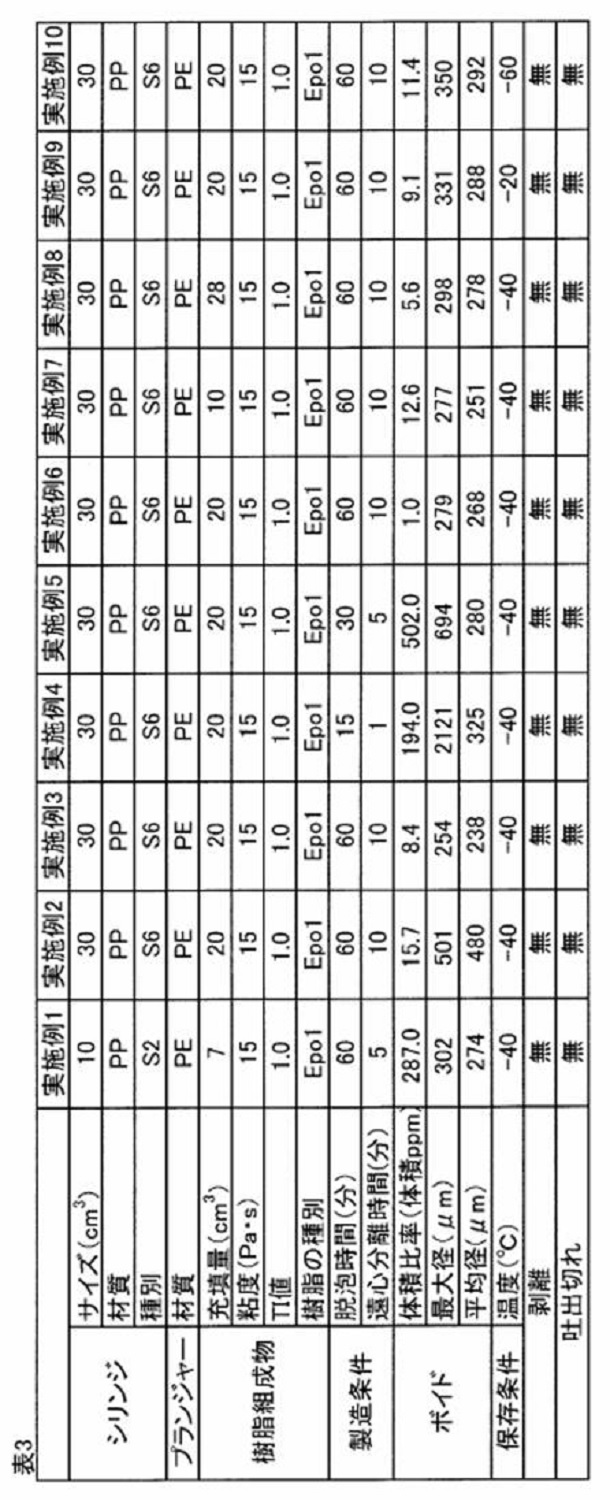
表3に示すように、実施例1~10の樹脂組成物充填済みシリンジでは、シリンジの大きさ、シリンジに充填される樹脂組成物の充填量、および保存温度が変化した場合であっても、樹脂組成物中に含まれるボイドの体積比率が1.0体積ppm~520体積ppmの範囲内であり、前記ボイドの最大径が2,500μm以下であれば、樹脂組成物に含有されているボイドによって、冷凍時の樹脂組成物の体積収縮を抑制することができた。これにより、樹脂組成物のシリンジの内壁からの剥離をなくすことができた。実施例1~10の樹脂組成物充填済みシリンジでは、吐出切れの原因となる大きなボイドを形成する空気が、樹脂組成物に混入されることを、抑制することができた。これにより、吐出切れをなくすことができた。
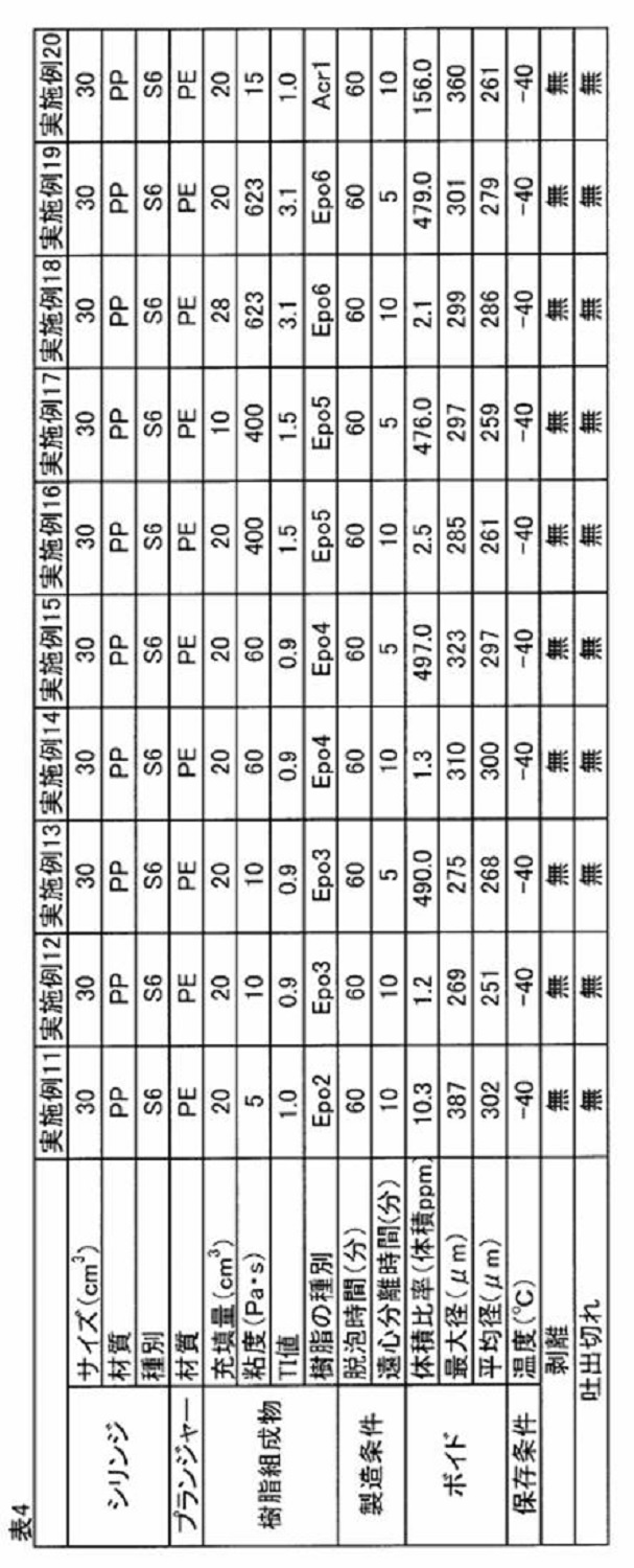
表4に示すように、実施例11~20の樹脂組成物充填済みシリンジでは、樹脂組成物に含まれる樹脂の種類が変化した場合であっても、樹脂組成物の25℃における粘度が2.5Pa・s~650Pa・sの範囲内であるか、又は、TI1~T13のTI値が0.8~3.5の範囲内であり、樹脂組成物中に含まれるボイドの体積比率が1.0体積ppm~520体積ppmの範囲内であり、かつ、前記ボイドの最大径が2,500μm以下であれば、樹脂組成物に含有されているボイドによって、冷凍時の樹脂組成物の体積収縮を抑制することができた。これにより、樹脂組成物のシリンジの内壁からの剥離をなくすことができた。実施例11~20の樹脂組成物充填済みシリンジでは、吐出切れの原因となる大きなボイドを形成する空気が、樹脂組成物混入されることを、抑制することができた。これにより、吐出切れをなくすことができた。

表5に示すように、実施例21~28の樹脂組成物充填済みシリンジでは、樹脂組成物を充填するシリンジの大きさ又は種類が異なる場合であっても、樹脂組成物中に含まれるボイドの体積比率が1.0体積ppm~520体積ppmの範囲内であり、前記ボイドの最大径が2,500μm以下であれば、樹樹脂組成物が含有するボイドによって、冷凍時の樹脂組成物の体積収縮を抑制することができた。これにより、樹脂組成物のシリンジの内壁からの剥離をなくすことができた。実施例21~28の樹脂組成物充填済みシリンジでは、吐出切れの原因となる大きなボイドを形成する空気が、樹脂組成物に混入されることを、抑制することができた。これにより、吐出切れをなくすことができた。

表6に示すように、比較例1、3、5の樹脂組成物充填済みシリンジでは、樹脂組成物に含まれるボイドの体積比率が520体積ppmを超えており、大きな体積のボイドが樹脂組成物に混入しており、吐出切れが発生した。また、比較例8の樹脂組成物充填済みシリンジでは、樹脂組成物に含まれるボイドの最大径が2,500μmを超える大きさであり、吐出切れが発生した。比較例2、4、6の樹脂組成物充填済みシリンジでは、樹脂組成物に含まれるボイドの体積比率が1.0体積ppm未満であり、樹脂組成物に含まれるボイドの量が少なすぎた。このため、冷凍時における樹脂組成物の体積変化を抑制することが困難であり、樹脂組成物がシリンジの内壁から剥離した。
図2に示すように、実施例1の樹脂組成物充填済みシリンジでは、吐出切れが発生しておらず、シリンジから吐出された樹脂組成物は、連続した軌跡を描いていた。図2は、実施例の樹脂組成物充填済みシリンジから吐出された、連続した軌跡100を示す。一方、図3に示すように、比較例1の樹脂組成物充填済みシリンジでは、樹脂組成物に含まれるボイドの体積比率が520体積ppmを超える大きさであるため、吐出切れが発生していた。このため、シリンジから吐出された樹脂組成物は、間欠的に途切れた軌跡を描いていた。図3は、比較例1の樹脂組成物充填済みシリンジから吐出された、途切れた軌跡101を示す。図3中、符号102は、吐出切れを示す。
本開示の実施形態に係る樹脂組成物充填済みシリンジは、粘性材料が充填されたシリンジとして、好適に使用されることができる。粘性材料は、たとえば、機械部品又は電子部品のシーラント、接着剤、電気・電子回路形成用ペースト、および、電子部品実装用はんだ、である。
1:シリンジ、2:樹脂組成物、3:プランジャー、4:ボイド(空隙)、11:縮径された開口部、12:開口部、13:フランジ、21:チップキャップ、22:ヘッドキャップ、100:連続した軌跡、101:途切れた軌跡、102:吐出切れ
Claims (8)
- シリンジと、シリンジ内に充填された樹脂組成物と、プランジャーとを含み、
前記樹脂組成物がボイドを含有し、
前記樹脂組成物の体積に対する前記ボイドの体積比率は、1.0体積ppm~520体積ppmであり、
前記ボイドの最大径が2,500μm以下である、
樹脂組成物充填済みシリンジ。 - 前記ボイドの平均径が200μm~400μm以下である、
請求項1に記載の樹脂組成物充填済みシリンジ。 - 前記樹脂組成物が、エポキシ樹脂及びアクリル樹脂から選ばれる少なくとも1種の樹脂を含む、
請求項1又は2に記載の樹脂組成物充填済みシリンジ。 - 前記樹脂組成物が、回転粘度計を用いて、25℃で、200Pa・s未満の粘度を50rpmの回転数で測定したとき、および、200Pa・s以上の粘度を10rpmの回転数で測定したときに、2.5Pa・s~650Pa・sの粘度を有する、請求項1~3のいずれか1項に記載の樹脂組成物充填済みシリンジ。
- 前記樹脂組成物における、以下(1)から(3)のいずれかの条件で測定されたチキソトロピーインデックスTI1~T13が、0.8~3.5である、
請求項1~4のいずれか1項に記載の樹脂組成物充填済みシリンジ。
(1)回転粘度計を用いて25℃で測定された50rpmの粘度が、2.5Pa・s以上20Pa・s未満の範囲内であり、5rpmの粘度と50rpmの粘度との比率である、チキソトロピーインデックスTI1、
(2)回転粘度計を用いて25℃で測定された50rpmの粘度が、20Pa・s以上200Pa・s未満の範囲内であり、5rpmの粘度と50rpmnの粘度との比率である、チキソトロピーインデックスTI2、
(3)回転粘度計を用いて25℃で測定された10rpmの粘度が、200Pa・s以上1,000Pa・s以下の範囲内であり、1rpmの粘度と10rpmの粘度との比率である、チキソトロピーインデックスTI3。 - 前記シリンジが、ポリプロピレン製又はポリエチレン製である、
請求項1~5のいずれか1項に記載の樹脂組成物充填済みシリンジ。 - 前記シリンジの容積が、1cm3~600cm3である、
請求項1~6のいずれか1項に記載の樹脂組成物充填済みシリンジ。 - 前記請求項1~7のいずれか1項に記載の樹脂組成物充填済みシリンジを、-80℃~0℃の温度で保存すること、を含む、
樹脂組成物充填済みシリンジの保存方法。
Priority Applications (3)
| Application Number | Priority Date | Filing Date | Title |
|---|---|---|---|
| CN202080008541.2A CN113286666B (zh) | 2019-02-08 | 2020-01-29 | 填充有树脂组合物的注射器及其保存方法 |
| KR1020217019270A KR102681327B1 (ko) | 2019-02-08 | 2020-01-29 | 수지 조성물이 충전된 시린지 및 그 보존 방법 |
| US17/414,754 US11850625B2 (en) | 2019-02-08 | 2020-01-29 | Syringe filled with resin composition and storage method therefor |
Applications Claiming Priority (2)
| Application Number | Priority Date | Filing Date | Title |
|---|---|---|---|
| JP2019-021653 | 2019-02-08 | ||
| JP2019021653A JP7217003B2 (ja) | 2019-02-08 | 2019-02-08 | 樹脂組成物充填済みシリンジ及びその保存方法 |
Publications (1)
| Publication Number | Publication Date |
|---|---|
| WO2020162274A1 true WO2020162274A1 (ja) | 2020-08-13 |
Family
ID=71947668
Family Applications (1)
| Application Number | Title | Priority Date | Filing Date |
|---|---|---|---|
| PCT/JP2020/003084 Ceased WO2020162274A1 (ja) | 2019-02-08 | 2020-01-29 | 樹脂組成物充填済みシリンジ及びその保存方法 |
Country Status (6)
| Country | Link |
|---|---|
| US (1) | US11850625B2 (ja) |
| JP (2) | JP7217003B2 (ja) |
| KR (1) | KR102681327B1 (ja) |
| CN (1) | CN113286666B (ja) |
| TW (1) | TWI824106B (ja) |
| WO (1) | WO2020162274A1 (ja) |
Cited By (1)
| Publication number | Priority date | Publication date | Assignee | Title |
|---|---|---|---|---|
| CN117136105A (zh) * | 2021-03-29 | 2023-11-28 | 太阳控股株式会社 | 墨填充完毕的墨盒 |
Families Citing this family (2)
| Publication number | Priority date | Publication date | Assignee | Title |
|---|---|---|---|---|
| JP7217003B2 (ja) * | 2019-02-08 | 2023-02-02 | ナミックス株式会社 | 樹脂組成物充填済みシリンジ及びその保存方法 |
| JP7540347B2 (ja) * | 2021-01-19 | 2024-08-27 | 味の素株式会社 | 樹脂組成物及び樹脂組成物充填済みシリンジ |
Citations (4)
| Publication number | Priority date | Publication date | Assignee | Title |
|---|---|---|---|---|
| JP2007533450A (ja) * | 2004-04-21 | 2007-11-22 | ノードソン コーポレーション | シリンジ及びシリンジを製造する方法 |
| JP2011031176A (ja) * | 2009-07-31 | 2011-02-17 | Casio Computer Co Ltd | 吐出ノズル、吐出装置、気泡の検出方法及び気泡の除去方法 |
| US20170253351A1 (en) * | 2016-03-02 | 2017-09-07 | The Boeing Company | In-line centrifugal sealant debubbler |
| WO2018168587A1 (ja) * | 2017-03-13 | 2018-09-20 | ナミックス株式会社 | 充填済みシリンジ、および樹脂組成物の保存方法 |
Family Cites Families (19)
| Publication number | Priority date | Publication date | Assignee | Title |
|---|---|---|---|---|
| US2591046A (en) * | 1948-10-18 | 1952-04-01 | Frederick M Turnbull | Hypodermic syringe assembly |
| US4846796A (en) * | 1988-07-27 | 1989-07-11 | Rialto Enterprises, Ltd. | Protective system for safe disposition of a syringe and hypodermic injection device carried thereon |
| NZ244576A (en) * | 1989-02-08 | 1994-11-25 | Becton Dickinson Co | Syringe barrel with contrast band opposite indicia to improve readability |
| US5016784A (en) * | 1990-02-15 | 1991-05-21 | Dexus Research Inc. | Applicator for highly reactive materials |
| DE4445969C1 (de) * | 1994-12-22 | 1996-03-14 | Schott Glaswerke | Spritzenzylinder für eine Zweikammer-Fertigspritze, Zweikammer-Fertigspritze und Verfahren zum Herstellen und Füllen derselben |
| US5779668A (en) * | 1995-03-29 | 1998-07-14 | Abbott Laboratories | Syringe barrel for lyophilization, reconstitution and administration |
| JP3980115B2 (ja) * | 1997-04-22 | 2007-09-26 | 松下電器産業株式会社 | 電子部品接着用ボンドの塗布装置 |
| US5971953A (en) * | 1998-01-09 | 1999-10-26 | Bachynsky; Nicholas | Dual chamber syringe apparatus |
| US6386396B1 (en) * | 2001-01-31 | 2002-05-14 | Hewlett-Packard Company | Mixing rotary positive displacement pump for micro dispensing |
| CN1622873A (zh) | 2002-01-23 | 2005-06-01 | 铃鹿富士施乐株式会社 | 再生热塑性树脂成型品的制造方法 |
| US20040108334A1 (en) * | 2002-01-28 | 2004-06-10 | Strecker Timothy D. | Mixing rotary positive displacement pump for micro dispensing |
| US9782542B2 (en) * | 2009-10-01 | 2017-10-10 | Momentive Performance Materials Inc. | Self-lubricating pharmaceutical syringe stoppers |
| US8618185B2 (en) * | 2009-10-01 | 2013-12-31 | Momentive Performance Materials Inc. | Self-lubricating pharmaceutical syringe stoppers |
| JP2011183323A (ja) | 2010-03-10 | 2011-09-22 | Panasonic Corp | 塗布方法および塗布装置 |
| JP4659128B1 (ja) | 2010-08-24 | 2011-03-30 | 加賀ワークス株式会社 | 粘性材料充填方法 |
| JP6320838B2 (ja) | 2014-05-02 | 2018-05-09 | 株式会社トクヤマ | (メタ)アクリル基を有する重合体で被覆された金属酸化物粒子及びその製造方法 |
| JP6643158B2 (ja) | 2016-03-23 | 2020-02-12 | ナミックス株式会社 | エポキシ樹脂組成物、アンダーフィル剤、硬化物、半導体装置 |
| CN108883232A (zh) * | 2016-04-25 | 2018-11-23 | 泰尔茂株式会社 | 用于预灌封注射器的注射器主体、注射器装置及预灌封注射器 |
| JP7217003B2 (ja) * | 2019-02-08 | 2023-02-02 | ナミックス株式会社 | 樹脂組成物充填済みシリンジ及びその保存方法 |
-
2019
- 2019-02-08 JP JP2019021653A patent/JP7217003B2/ja active Active
-
2020
- 2020-01-29 US US17/414,754 patent/US11850625B2/en active Active
- 2020-01-29 WO PCT/JP2020/003084 patent/WO2020162274A1/ja not_active Ceased
- 2020-01-29 KR KR1020217019270A patent/KR102681327B1/ko active Active
- 2020-01-29 CN CN202080008541.2A patent/CN113286666B/zh active Active
- 2020-02-05 TW TW109103451A patent/TWI824106B/zh active
-
2022
- 2022-12-02 JP JP2022193313A patent/JP7381138B2/ja active Active
Patent Citations (4)
| Publication number | Priority date | Publication date | Assignee | Title |
|---|---|---|---|---|
| JP2007533450A (ja) * | 2004-04-21 | 2007-11-22 | ノードソン コーポレーション | シリンジ及びシリンジを製造する方法 |
| JP2011031176A (ja) * | 2009-07-31 | 2011-02-17 | Casio Computer Co Ltd | 吐出ノズル、吐出装置、気泡の検出方法及び気泡の除去方法 |
| US20170253351A1 (en) * | 2016-03-02 | 2017-09-07 | The Boeing Company | In-line centrifugal sealant debubbler |
| WO2018168587A1 (ja) * | 2017-03-13 | 2018-09-20 | ナミックス株式会社 | 充填済みシリンジ、および樹脂組成物の保存方法 |
Cited By (1)
| Publication number | Priority date | Publication date | Assignee | Title |
|---|---|---|---|---|
| CN117136105A (zh) * | 2021-03-29 | 2023-11-28 | 太阳控股株式会社 | 墨填充完毕的墨盒 |
Also Published As
| Publication number | Publication date |
|---|---|
| JP7381138B2 (ja) | 2023-11-15 |
| US11850625B2 (en) | 2023-12-26 |
| CN113286666B (zh) | 2023-08-25 |
| JP2020127919A (ja) | 2020-08-27 |
| TW202042917A (zh) | 2020-12-01 |
| TWI824106B (zh) | 2023-12-01 |
| JP2023026442A (ja) | 2023-02-24 |
| JP7217003B2 (ja) | 2023-02-02 |
| KR102681327B1 (ko) | 2024-07-03 |
| US20220072582A1 (en) | 2022-03-10 |
| CN113286666A (zh) | 2021-08-20 |
| KR20210124192A (ko) | 2021-10-14 |
Similar Documents
| Publication | Publication Date | Title |
|---|---|---|
| JP7381138B2 (ja) | 樹脂組成物充填済みシリンジ及びその保存方法 | |
| JP7364257B2 (ja) | 樹脂組成物充填済みシリンジ、その製造方法及び保存方法 | |
| CN104024365B (zh) | 活性能量线固化性树脂组合物、其制造方法及使用其的密封材料 | |
| JPH0617024A (ja) | 良熱伝導性接着剤 | |
| KR100189282B1 (ko) | 실온에서 안정한, 일성분계 가요성 에폭시 접착제 | |
| TWI810310B (zh) | 液狀吸濕劑及電子機器的製造方法 | |
| JP2017179092A (ja) | 活性エネルギー線硬化性樹脂組成物、その硬化物からなるシール材及び緩衝材 | |
| JPH11323297A (ja) | 接着剤組成物 | |
| JP2023129848A (ja) | 硬化性樹脂組成物、接着剤、および接着方法 | |
| JP2000169820A (ja) | 接着剤組成物 | |
| JP3923687B2 (ja) | 電子部品実装用接合剤およびこれを用いた電子部品の実装方法 | |
| EP0859027B1 (en) | Curable compositions | |
| JP6385116B2 (ja) | 加熱硬化型エポキシ樹脂用硬化剤及びそれを含む一液性加熱硬化型エポキシ樹脂組成物 | |
| JP2009091392A (ja) | 芳香族アミン組成物 | |
| JP6020918B2 (ja) | 硬化性樹脂組成物 | |
| EP4566807A1 (en) | An adhesive sheet | |
| JPH10204383A (ja) | 刷毛塗り可能な安定性に優れた嫌気硬化性組成物 | |
| JP7144085B1 (ja) | シリンジ、吐出装置及び塗布方法 | |
| JP2002284846A (ja) | 一液型エポキシ樹脂組成物 | |
| JP2004292764A (ja) | 電気コイル注型用二液型エポキシ樹脂組成物 | |
| JP2021070753A (ja) | 接着剤セット、構造体及び構造体の製造方法 | |
| JP2020045376A (ja) | 紛体状エポキシ硬化剤及びエポキシ注型材 | |
| JP2008266357A (ja) | エポキシ樹脂組成物 | |
| JPH10265651A (ja) | 液晶セルの組立用シール材組成物及びそれを用いた液晶表示素子 | |
| HK1012670B (en) | Room-temperature stable, one-component, flexible epoxy adhesives |
Legal Events
| Date | Code | Title | Description |
|---|---|---|---|
| 121 | Ep: the epo has been informed by wipo that ep was designated in this application |
Ref document number: 20752158 Country of ref document: EP Kind code of ref document: A1 |
|
| ENP | Entry into the national phase |
Ref document number: 20217019270 Country of ref document: KR Kind code of ref document: A |
|
| NENP | Non-entry into the national phase |
Ref country code: DE |
|
| 122 | Ep: pct application non-entry in european phase |
Ref document number: 20752158 Country of ref document: EP Kind code of ref document: A1 |