WO2020162044A1 - 光ファイバの融着接続方法及び融着接続装置 - Google Patents
光ファイバの融着接続方法及び融着接続装置 Download PDFInfo
- Publication number
- WO2020162044A1 WO2020162044A1 PCT/JP2019/049007 JP2019049007W WO2020162044A1 WO 2020162044 A1 WO2020162044 A1 WO 2020162044A1 JP 2019049007 W JP2019049007 W JP 2019049007W WO 2020162044 A1 WO2020162044 A1 WO 2020162044A1
- Authority
- WO
- WIPO (PCT)
- Prior art keywords
- optical fiber
- groove
- clamp
- optical fibers
- fusion splicing
- Prior art date
Links
Images


Classifications
-
- G—PHYSICS
- G02—OPTICS
- G02B—OPTICAL ELEMENTS, SYSTEMS OR APPARATUS
- G02B6/00—Light guides; Structural details of arrangements comprising light guides and other optical elements, e.g. couplings
- G02B6/24—Coupling light guides
- G02B6/255—Splicing of light guides, e.g. by fusion or bonding
- G02B6/2555—Alignment or adjustment devices for aligning prior to splicing
-
- G—PHYSICS
- G02—OPTICS
- G02B—OPTICAL ELEMENTS, SYSTEMS OR APPARATUS
- G02B6/00—Light guides; Structural details of arrangements comprising light guides and other optical elements, e.g. couplings
- G02B6/24—Coupling light guides
- G02B6/255—Splicing of light guides, e.g. by fusion or bonding
- G02B6/2551—Splicing of light guides, e.g. by fusion or bonding using thermal methods, e.g. fusion welding by arc discharge, laser beam, plasma torch
-
- G—PHYSICS
- G02—OPTICS
- G02B—OPTICAL ELEMENTS, SYSTEMS OR APPARATUS
- G02B6/00—Light guides; Structural details of arrangements comprising light guides and other optical elements, e.g. couplings
- G02B6/24—Coupling light guides
- G02B6/255—Splicing of light guides, e.g. by fusion or bonding
- G02B6/2555—Alignment or adjustment devices for aligning prior to splicing
- G02B6/2557—Alignment or adjustment devices for aligning prior to splicing using deformable flexure members, flexible hinges or pivotal arms
-
- G—PHYSICS
- G02—OPTICS
- G02B—OPTICAL ELEMENTS, SYSTEMS OR APPARATUS
- G02B6/00—Light guides; Structural details of arrangements comprising light guides and other optical elements, e.g. couplings
- G02B6/24—Coupling light guides
- G02B6/255—Splicing of light guides, e.g. by fusion or bonding
- G02B6/2553—Splicing machines, e.g. optical fibre fusion splicer
Definitions
- the present disclosure relates to an optical fiber fusion splicing method and a fusion splicing device.
- This application claims priority based on Japanese Patent Application No. 2019-19542 filed on February 6, 2019, and incorporates all the contents described in the Japanese application.
- Patent Document 1 discloses an optical fiber fusion splicing method in which an optical fiber to be spliced is positioned in a V groove for fusion splicing. In this method, the optical fiber placed in the V groove is retracted, then the optical fiber is advanced, and the optical fiber is placed in the V groove again.
- An optical fiber fusion splicing method is an optical fiber fusion splicing method in which an optical fiber to be connected is positioned in a V groove to perform fusion splicing. To relatively push the optical fiber toward the V groove by a clamp, to change the clamp pressure of the clamp for pressing the optical fiber, and to move the optical fiber placed in the V groove to the V groove along the axial direction. And a step of relatively moving it.
- An optical fiber fusion splicer is a V groove in which an optical fiber is placed, a clamp that relatively presses the optical fiber placed in the V groove into the V groove, and an optical fiber. It includes a clamp pressure changing mechanism that changes the clamp pressure of the clamp, and a moving mechanism that moves the optical fiber placed in the V groove relative to the V groove along the axial direction.
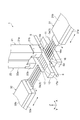
- FIG. 1 is a perspective view showing a part of a fusion splicing device according to an example.
- FIG. 2 is a sectional view showing a part of the fusion splicer.
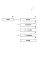
- FIG. 3 is a block diagram showing a control system of the fusion splicer.
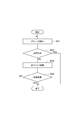
- FIG. 4 is a flowchart showing an example of the operation of the fusion splicer.
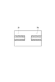
- FIG. 5 is a diagram showing a state in which foreign matter is present in the V groove of the fusion splicer.
- FIG. 6 is a diagram schematically illustrating an example of an image acquired by the imaging device of the fusion splicing device.
- FIG. 7 is a figure which shows typically an example of the image acquired by the imaging device of a fusion splicing apparatus.
- FIG. 1 is a perspective view showing a part of a fusion splicing device according to an example.
- FIG. 2 is a sectional view showing a part of the fusion splicer.
- FIG. 8 is a flowchart showing an example of the removing operation by the fusion splicing device.
- FIG. 9 is a flowchart showing another example of the removing operation by the fusion splicing device.
- FIG. 10 is a block diagram showing a control system of the fusion splicer according to another example.
- FIG. 11 is a flowchart showing an example of the operation of the fusion splicer.
- FIG. 12 is a flowchart showing an example of the removing operation by the fusion splicing device.
- FIG. 13 is a flowchart showing another example of the removing operation by the fusion splicing device.
- a highly accurate splice can be performed by cleaning the optical fiber and the V-groove before performing fusion splicing.
- dust or the like left in the step of cleaning the optical fiber or the like adheres to the V groove, the end faces of the pair of fibers cannot be aligned vertically, and it may not be possible to perform highly accurate connection. Therefore, as described in Patent Document 1, a method of removing dust and the like in the V groove by retreating and advancing the optical fiber placed in the V groove has been devised. In this field, there is a demand for more reliable removal of dust and the like in the V groove.
- An optical fiber fusion splicing method is an optical fiber fusion splicing method in which an optical fiber to be connected is positioned in a V groove to perform fusion splicing.
- An optical fiber fusion splicer includes a V groove in which the optical fiber is placed, a clamp that relatively presses the optical fiber placed in the V groove into the V groove, and an optical fiber. It includes a clamp pressure changing mechanism for changing the clamp pressure of the clamp for pressing and a moving mechanism for moving the optical fiber placed in the V groove relative to the V groove along the axial direction.
- the optical fiber placed in the V groove is relatively pressed into the V groove by the clamp, and thereby the optical fiber is positioned in the V groove.
- foreign matter such as dust
- the foreign matter may move due to the change of the clamp pressure and the movement of the optical fiber in the axial direction.
- the change in the clamp pressure and the movement of the optical fiber have different directions of the force acting on the foreign matter, so that the foreign matter can be effectively moved (removed).
- the step of changing the clamp pressure and the step of moving the optical fiber along the axial direction may be performed at the same time.
- the clamp pressure changing mechanism may be a mechanism that changes the position of the clamp with respect to the V groove while the position of the V groove is fixed. With this configuration, since a mechanism for changing the position of the V groove is not required, it is possible to prevent the device configuration from becoming complicated.
- the clamp pressure changing mechanism may be a mechanism that changes the position of the V groove with respect to the clamp while the position of the clamp is fixed. In this configuration, since the mechanism for changing the position of the V groove is included, the position of the optical fiber positioned in the V groove can be adjusted.
- FIG. 1 is a perspective view showing a part 1 of the optical fiber fusion splicer.
- FIG. 2 is an enlarged sectional view showing a part 1 of the fusion splicer.
- FIG. 3 is a block diagram showing a control system for controlling the fusion splicer.
- the fusion splicing device is a device for splicing and splicing a plurality of pairs of optical fibers (glass fibers) 3 arranged with their end faces butted against each other by arc discharge.
- the fusion splicing device includes a pair of electrode rods 5 and 6, a pair of bases 11 and 12, a pair of clamps 21 and 22, and a pair of holders 31 and 32.
- the pair of electrode rods 5 and 6 are arranged apart from each other in the X direction.
- the electrode rod 5 and the electrode rod 6 are arranged so that the tips 5a and 6a face each other.
- the electrode rods 5 and 6 include substantially conical portions whose diameter decreases toward the tips 5a and 6a.
- a plurality of pairs of optical fibers 3 can be arranged between a pair of electrode rods 5, 6 for generating an arc discharge.
- the pair of bases 11 and 12 are arranged at positions sandwiching the pair of electrode rods 5 and 6. That is, the pair of electrode rods 5 and 6 are arranged between the base 11 and the base 12 which are separated from each other in the Y direction.
- the base 11 in the illustrated example has an optical fiber arrangement portion 16, and the base 12 has an optical fiber arrangement portion 17.
- the optical fiber placement unit 16 has a plurality of V grooves 16a for placing a plurality of optical fibers 3a, respectively.
- the V grooves 16a are arranged at equal intervals in the X direction, and are formed linearly along the Y direction.
- the optical fiber placement unit 17 has a plurality of V grooves 17a for placing a plurality of optical fibers 3b, respectively.
- the V grooves 17a are arranged at equal intervals in the X direction, and are formed linearly along the Y direction.
- the V groove 16a of the optical fiber placement portion 16 and the V groove 17a of the optical fiber placement portion 17 position the plurality of pairs of optical fibers 3.
- each of the plurality of V-grooves 16a of the optical fiber placement portion 16 and each of the plurality of V-grooves 17a of the optical fiber placement portion 17 face each other.
- the optical fiber 3a positioned by the V groove 16a of the optical fiber placement unit 16 and the optical fiber 3b positioned by the V groove 17a of the optical fiber placement unit 17 are the optical fiber placement unit 16 and the optical fiber placement unit. In the area between 17 and 17 they can abut each other.
- the pair of clamps 21 and 22 relatively press the optical fiber 3 placed in the V grooves 16a and 17a against the V grooves 16a and 17a.
- the illustrated clamps 21, 22 include arm portions 21a, 22a and pressing portions 21b, 22b.
- the arm portion 21 a is arranged above the optical fiber arrangement portion 16, and the arm portion 22 a is arranged above the optical fiber arrangement portion 17.
- the pair of arm portions 21a and 22a are provided so as to be movable in the vertical direction.
- the arm portions 21a and 22a may have a substantially rectangular column shape.
- the pressing portion 21b is attached to the lower end of the arm portion 21a, and the pressing portion 22b is attached to the lower end of the arm portion 22a.
- the pressing portion 21b is movable in the vertical direction (Z direction) at the lower end of the arm portion 21a
- the pressing portion 22b is movable in the vertical direction (Z direction) at the lower end of the arm portion 22a. ing.
- the pressing portions 21b and 22b are separated from the optical fibers 3a and 3b arranged in the V-grooves 16a and 17a, but the pressing portions 21b and 22a move downward, 22b can press the optical fibers 3a and 3b toward the V grooves 16a and 17a.
- the clamp pressure of the clamps 21 and 22 can be changed.
- the clamp pressure may be a pressure received when the optical fibers 3a and 3b arranged in the V grooves 16a and 17a are pressed by the pressing portions 21b and 22b of the clamps 21 and 22.
- an elastic body such as a spring that biases the pressing portions 21b and 22b downward may be arranged between the arm portions 21a and 22a and the pressing portions 21b and 22b.
- the clamp pressure can be controlled by controlling the positions of the arm portions 21a and 22a in the vertical direction.
- the holders 31 and 32 hold the optical fiber 3.
- the tape core wire 4 including the plurality of optical fibers 3 is held by the holders 31 and 32.
- the holders 31 and 32 have holder bodies 31a and 32a having recesses for accommodating the tape core wire 4, and lid bodies 31b and 32b attached to the holder bodies 31a and 32a.
- the tape cores 4 are held by the holders 31 and 32 by closing the lids 31b and 32b with the tape cores 4 accommodated in the holder bodies 31a and 32a.
- the holders 31 and 32 are movable in the direction along the axis of the held optical fiber 3. That is, the holders 31 and 32 are movable along the extending direction of the V grooves 16a and 17a (that is, the Y direction).
- the held optical fiber 3 can move forward and backward along the V grooves 16a and 17a.
- the forward movement means that the held optical fibers 3a and 3b move toward each other.
- the backward movement means that the held optical fibers 3a and 3b move in a direction away from each other.
- the fusion splicing device includes an imaging device 51, a fusion splicing mechanism 52, a clamp drive mechanism 53, a holder drive mechanism 54, and a display device 55.
- the imaging device 51, the fusion splicing mechanism 52, the clamp driving mechanism 53, the holder driving mechanism 54, and the display device 55 are controlled by the control unit 60.
- the control unit 60 may be a computer including a CPU (Central Processing Unit), a RAM (Random Access Memory), a ROM (Read Only Memory), a communication module, a hard disk, and the like.
- the image pickup device 51 is configured to include, for example, a pair of cameras.
- the pair of cameras images the end portions of the pair of optical fibers 3a and 3b placed in the V grooves 16a and 17a.
- the imaging direction of the pair of cameras may be a direction intersecting with the axial direction of the optical fibers 3a and 3b placed in the V grooves 16a and 17a.
- the imaging directions of the pair of cameras may intersect with each other.
- the imaging direction of the pair of cameras is a direction orthogonal to the axial direction of the optical fibers 3a and 3b placed in the V grooves 16a and 17a.
- the imaging directions of the pair of cameras are orthogonal to each other.
- the position of the optical fiber can be specified by imaging the optical fiber from two different directions using a pair of cameras.
- the fusion splicing mechanism 52 is a mechanism for fusion splicing the ends of the pair of optical fibers 3a and 3b, and includes a pair of electrode rods 5 and 6.
- the clamp drive mechanism 53 includes an actuator that vertically moves the arm portions 21a and 22a forming the clamps 21 and 22.
- the holder drive mechanism 54 includes an actuator that moves the holders 31, 32 in a direction along the axial direction of the optical fibers 3a, 3b.
- the display device 55 can display the image captured by the imaging device 51.
- the control unit 60 controls the imaging device 51 to acquire the image captured by the imaging device 51.
- the acquired image may be displayed on the display device 55, for example.
- the control unit 60 determines the state of the pair of optical fibers 3a and 3b by performing image processing on the acquired image.
- the control unit 60 controls the fusion splicing mechanism 52 to generate arc discharge between the pair of electrode rods 5 and 6.
- the control unit 60 controls the clamp drive mechanism (clamp pressure control mechanism) 53 to move the arm portions 21a and 22a of the clamps 21 and 22 in the vertical direction. Under the control of the control unit 60, the clamps 21 and 22 can change the pressing state of the optical fibers 3a and 3b arranged in the V grooves 16a and 17a.
- control unit 60 controls the holder driving mechanism 54 to control the positions of the holders 31 and 32 in the Y direction. Under the control of the control unit 60, the holders 31 and 32 move forward and backward, and the optical fibers 3a and 3b held by the holders 31 and 32 move forward and backward.
- FIG. 4 is a flowchart showing an example of the operation of the fusion splicer.
- the holder driving mechanism 54 is driven by the control unit 60, and the holders 31 and 32 move along the axial center directions of the optical fibers 3a and 3b.
- the tips of the optical fibers 3a and 3b set in the holders 31 and 32 move to the inside of the image pickup range of the image pickup device 51, and the end face abutment is executed (step S1).
- the distance between the end faces of the optical fibers 3a and 3b is adjusted so that the predetermined distance is suitable for the fusion splicing of the optical fibers 3a and 3b. That is, the holders 31 and 32 move so that the end faces of the optical fibers 3a and 3b come close to each other.
- FIG. 5 is a diagram showing an example of the optical fibers 3a and 3b when foreign matter G such as dust is present in one V groove 17a.
- FIG. 6 schematically shows an image taken by the imaging device 51 in the state of FIG.
- FIG. 7 schematically shows an image taken by the imaging device 51 when the axes of the pair of optical fibers 3a and 3b are aligned with each other. Note that the flange is omitted in FIG. Further, in FIGS. 6 and 7, the clad portion covering the periphery of the core in the optical fiber is hatched.
- the optical fiber 3b may not be positioned in the V groove 17a, and the tip side of the optical fiber 3b may tilt upward.
- the shift amount may be the shift amount of the position of the core of the optical fiber in the vertical direction of the paper surface of FIG.
- the position of the core can be specified based on the brightness value of the image, for example.
- step S4 when the displacement amount between the pair of optical fibers 3a and 3b is less than or equal to a predetermined amount, discharge is performed between the pair of electrode rods 5 and 6, and the optical fibers 3a and 3b are heated, It is melted and connected (step S4). Then, the post-fusion inspection is performed based on the images obtained by imaging the optical fibers 3a and 3b that are fusion-spliced (step S5).
- FIG. 8 is a flowchart showing an example of the removing operation.
- the clamp pressure is changed (step S11).
- the control unit 60 controls the clamp drive mechanism 53 so that the clamp pressures of the clamps 21 and 22 temporarily change. For example, even if the clamps 21 and 22 are raised so as to release the optical fibers 3a and 3b pressed toward the V grooves 16a and 17a, and then the clamps 21 and 22 are lowered to return the clamp pressure to the original state. Good.
- clamp pressure of the clamps 21 and 22 is changed so as to press the optical fibers 3a and 3b arranged in the V grooves 16a and 17a toward the V grooves 16a and 17a with a larger force, and then the clamp 21 , 22 may be returned to the original clamp pressure.
- step S12 the axis deviation inspection is executed again (step S12).
- This axis deviation inspection is similar to the axis deviation inspection in step S2. If there is no problem in this axis misalignment inspection, that is, if it is determined that the misalignment amount is less than or equal to the predetermined amount, the removing operation is ended and the process proceeds to step S4. On the other hand, if it is determined in the axis deviation inspection in step S12 that the deviation amount is larger than the predetermined amount, that is, if the deviation amount is not equal to or smaller than the predetermined amount, the process proceeds to step S13.
- step S13 the control unit 60 controls the holder driving mechanism 54 to move the optical fibers 3a and 3b placed in the V grooves 16a and 17a along the axial direction (Y direction in the illustrated example). For example, the optical fibers 3a and 3b are moved backward, and then the optical fibers 3a and 3b are moved forward to return the optical fibers to their original positions.
- step S14 the axis deviation inspection is executed again (step S14).
- This axis deviation inspection is similar to the axis deviation inspection in step S2. Therefore, if there is no problem in this axis deviation inspection, that is, if it is determined that the deviation amount is less than or equal to the predetermined amount, the removing operation is ended, and the process proceeds to step S4.
- the process returns to step S11. If a problem occurs in the axis misalignment inspection even if the removing operation in step S3 is performed a plurality of times (for example, twice), an error message may be displayed on the display device 55 and the process may be terminated.
- FIG. 9 is a flowchart showing another example of the removing operation.
- the removing operation shown in FIG. 9 may be executed as the removing operation in step S3.
- the change of the clamp pressure and the movement of the optical fibers 3a and 3b are executed in parallel (step S21).
- the optical fibers 3a and 3b are moved backward with the clamping pressure being increased, and then the optical fibers 3a and 3b are moved forward while maintaining the state where the clamping pressure is large, to return the optical fibers to the original state. You may return to the position.
- the optical fibers 3a and 3b may move in the front-rear direction by about 0.5 mm.
- the optical fibers 3a and 3b may be moved backward without changing the clamping pressure, and then the optical fibers 3a and 3b may be moved forward with the clamping pressure increased. ..
- the state where the clamp pressure is increased, the state where the clamp pressure is not changed, the state where the optical fiber is released (the state where the clamp pressure is reduced, the clamp pressure is zero), and the optical fiber 3a are used.
- 3b can be appropriately combined with the backward movement and the forward movement.
- the magnitude of the clamp pressure may be changed during the backward movement (or forward movement) of the optical fibers 3a and 3b.
- the state in which the clamp pressure is high and the state in which the clamp pressure is low may be repeated during the backward movement (or forward movement) of the optical fibers 3a and 3b.
- step S22 the axis deviation inspection is executed again (step S22).
- This axis deviation inspection is similar to the axis deviation inspection in step S2. Therefore, if there is no problem in this axis deviation inspection, that is, if it is determined that the deviation amount is less than or equal to the predetermined amount, the removing operation is ended, and the process proceeds to step S4.
- the process returns to step S21.
- the optical fibers 3 placed in the V-grooves 16a and 17a are relatively pressed against the V-grooves 16a and 17a by the clamps 21 and 22 so that the V-grooves 16a and 17a are exposed to light.
- the fiber 3 is positioned.
- foreign matter G such as dust is present in the V-grooves 16a and 17a
- the optical fiber 3 cannot be properly positioned in the V-grooves 16a and 17a.
- the foreign matter G and the optical fiber 3 are in contact with each other, the foreign matter G can move due to the change in the clamp pressure and the movement of the optical fiber 3 in the axial direction.
- the magnitude of the force acting vertically on the foreign matter G in the V grooves 16a and 17a may change.
- the optical fiber 3 is moved in the axial direction, the magnitude of the force acting in the front-rear direction on the foreign matter G in the V grooves 16a and 17a may change. In this way, since the direction of the force acting on the foreign matter G is different between the change in the clamp pressure and the movement of the optical fiber 3, the foreign matter can be effectively moved (removed).
- the step of changing the clamp pressure and the step of moving the optical fiber 3 along the axial direction may be performed at the same time.
- two forces that act in mutually different directions can be applied to the foreign matter G simultaneously or continuously.
- the force acting in the up-down direction and the force acting in the front-rear direction are combined, whereby the force can act diagonally upward or diagonally downward on the foreign substance G.
- the clamp pressure is changed by vertically moving the arm portions 21a and 22a of the clamps 21 and 22.
- a base drive mechanism 56 is further provided in addition to the imaging device 51, the fusion splicing mechanism 52, the clamp drive mechanism 53, the holder drive mechanism 54, and the display device 55. Is included.
- the image pickup device 51, the fusion splicing mechanism 52, the clamp drive mechanism 53, the holder drive mechanism 54, and the display device 55 have the same configurations as those in the first embodiment, and therefore their explanations are omitted.
- the clamp drive mechanism 53 may not be able to change the clamp pressure.
- FIG. 1 is also referred to in the description of the second embodiment.
- the pair of bases 11 and 12 are configured to be movable in the vertical direction.
- the base drive mechanism 56 includes actuators that move the bases 11 and 12 in the vertical direction.
- the control unit 60 can control the positions of the bases 11 and 12 in the vertical direction by controlling the base drive mechanism 56.
- the pair of optical fibers 3a and 3b can be aligned by controlling the positions of the bases 11 and 12 in the vertical direction.
- the clamp pressure can be controlled (changed) by controlling the positions of the bases 11 and 12 in the vertical direction. That is, when the bases 11 and 12 are located at the reference position in the vertical direction and have a predetermined clamp pressure, the clamp pressure can be increased by moving the bases 11 and 12 upward. Further, when the base 11 or 12 has a predetermined clamp pressure in the vertical direction when the base 11 or 12 is at the reference position, the clamp pressure can be reduced by moving the base 11 or 12 downward.
- FIG. 11 is a flowchart showing an example of the operation of the fusion splicer of the second embodiment.
- the holder driving mechanism 54 is driven by the control unit 60, and the holders 31 and 32 move along the axial center directions of the optical fibers 3a and 3b.
- the holders 31 and 32 are moved so that the tips of the optical fibers 3a and 3b set in the holders 31 and 32 move to the inside of the imaging range of the imaging device 51 (step S31).
- step S32 The position inspection method is the same as the axis deviation inspection in step S2 of the first embodiment. In this position inspection, when it is determined that the tips of the optical fibers 3a and 3b are not located within the predetermined range, the removal operation of step S33 is performed.
- step S34 end face matching is executed (step S34).
- the distance between the end faces of the optical fibers 3a and 3b is adjusted so that the predetermined distance is suitable for the fusion splicing of the optical fibers 3a and 3b. That is, the holders 31 and 32 move so that the end faces of the optical fibers 3a and 3b come close to each other.
- step S35 alignment is executed (step S35).
- the control unit 60 controls the base driving mechanism 56 to move at least one of the bases 11 and 12 in the vertical direction so that the positions of the cores of the pair of optical fibers 3a and 3b are positioned with a predetermined accuracy. Match each other.
- the positions of the cores of the pair of optical fibers 3a and 3b are determined based on the image captured by the imaging device 51.
- electric discharge is performed between the pair of electrode rods 5 and 6, and the optical fibers are heated and fused and connected (step S36).
- the post-fusion inspection is performed based on the images obtained by imaging the optical fibers 3a and 3b that are fusion-spliced (step S37).
- FIG. 12 is a flowchart showing an example of the removing operation in step S33.
- the clamp pressure is changed (step S41).
- the control unit 60 controls the base drive mechanism 56 so that the clamp pressure temporarily changes.
- the control unit 60 controls the base drive mechanism 56 to move the bases 11 and 12 downward to release the optical fibers 3a and 3b which are relatively pressed toward the V grooves 16a and 17a.
- the bases 11 and 12 may be moved upward to return the clamp pressure to the original level.
- the bases 11 and 12 are moved upward to change the clamp pressure so as to press the optical fibers 3a and 3b arranged in the V grooves 16a and 17a toward the V grooves 16a and 17a with a larger force. After that, the bases 11 and 12 may be moved downward to return the clamp pressure to the original level.
- step S42 the position inspection is executed again (step S42). This position inspection is similar to the position inspection in step S32. If there is no problem in this position inspection, that is, if it is determined that the tips of the optical fibers 3a and 3b are located within the predetermined range, the removing operation is ended and the process proceeds to step S34. On the other hand, in the position inspection in step S42, when it is determined that the tips of the optical fibers 3a and 3b are not located within the predetermined range, the process proceeds to step S43. In step S43, the control unit 60 controls the holder driving mechanism 54 to move the optical fibers 3a and 3b placed in the V grooves 16a and 17a along the axial direction. For example, the optical fibers 3a and 3b are moved backward, and then the optical fibers 3a and 3b are moved forward to return the optical fibers to their original positions.
- step S44 the position inspection is executed again (step S44). This position inspection is similar to the position inspection in step S32. If there is no problem in this position inspection, that is, if it is determined that the tips of the optical fibers 3a and 3b are located within the predetermined range, the removing operation is ended and the process proceeds to step S34. On the other hand, in the position inspection in step S44, when it is determined that the tips of the optical fibers 3a and 3b are not located within the predetermined range, the process returns to step S41. If a problem occurs in the position inspection even if the removing operation of step S33 is performed a plurality of times (for example, twice), an error message may be displayed on the display device 55 and the process may be terminated.
- FIG. 13 is a flowchart showing another example of the removing operation.
- the removing operation shown in FIG. 13 may be executed as the removing operation in step S33.
- the change of the clamp pressure and the movement of the optical fibers 3a and 3b are executed in parallel (step S51).
- the clamp pressure is increased by raising the positions of the bases 11 and 12.
- the optical fibers 3a and 3b move backward with a large clamping pressure, and then the optical fibers 3a and 3b move forward with the large clamping pressure maintained to return the optical fibers to their original positions.
- the optical fibers 3a and 3b may move in the front-rear direction by about 0.5 mm.
- the optical fibers 3a and 3b are moved backward without changing the clamp pressure, and then the positions of the bases 11 and 12 are raised to increase the clamp pressure so that the light is emitted.
- the fibers 3a and 3b may be moved forward.
- the state where the clamp pressure is increased, the state where the clamp pressure is not changed, and the state where the optical fiber is released are appropriately combined with the backward movement and the forward movement of the optical fibers 3a and 3b.
- the magnitude of the clamp pressure may be changed during the backward movement (or forward movement) of the optical fibers 3a and 3b.
- the state in which the clamp pressure is high and the state in which the clamp pressure is low may be repeated during the backward movement (or forward movement) of the optical fibers 3a and 3b.
- step S52 the position inspection is executed again (step S52). This position inspection is similar to the position inspection in step S32. If there is no problem in this position inspection, that is, if it is determined that the tips of the optical fibers 3a and 3b are located within the predetermined range, the removing operation is ended and the process proceeds to step S34. On the other hand, in the position inspection in step S52, when it is determined that the tips of the optical fibers 3a and 3b are not located within the predetermined range, the process returns to step S51.
- the clamp pressure is changed by changing the position of the V groove using the base drive mechanism 56.
- the base drive mechanism 56 is a mechanism used for aligning the optical fiber, and can adjust the position of the optical fiber positioned in the V groove. With this configuration, it is not necessary to separately provide a mechanism for centering and a mechanism for changing the clamp pressure, and it is possible to prevent the apparatus configuration from becoming complicated.
- the fusion splicing device for fusion splicing multi-core fibers having a plurality of optical fibers
- the fusion splicing device is a single-core optical fiber formed by one optical fiber. It may be a device for fusion-splicing each other.
- the optical fiber moves along the V groove while the position of the V groove is fixed.
- the V groove that is, By moving the base, the optical fiber may be moved relative to the V groove along the axial direction.
- the fusion splicing device may have a moving mechanism that moves the bases 11 and 12 along the extending direction (Y direction) of the V groove.
Landscapes
- Physics & Mathematics (AREA)
- Engineering & Computer Science (AREA)
- Plasma & Fusion (AREA)
- General Physics & Mathematics (AREA)
- Optics & Photonics (AREA)
- Mechanical Coupling Of Light Guides (AREA)
Priority Applications (5)
| Application Number | Priority Date | Filing Date | Title |
|---|---|---|---|
| CN201980081337.0A CN113366355A (zh) | 2019-02-06 | 2019-12-13 | 光纤的熔接连接方法及熔接连接装置 |
| JP2020571025A JP7347762B2 (ja) | 2019-02-06 | 2019-12-13 | 光ファイバの融着接続方法 |
| US17/312,309 US20220026638A1 (en) | 2019-02-06 | 2019-12-13 | Optical fiber fusion splicing method and fusion splicing device |
| EP19914506.1A EP3923050A4 (en) | 2019-02-06 | 2019-12-13 | FIBER OPTIC FUSION SPLICE DEVICE AND FUSION SPLICE DEVICE |
| KR1020217017843A KR20210122771A (ko) | 2019-02-06 | 2019-12-13 | 광섬유의 융착 접속 방법 및 융착 접속 장치 |
Applications Claiming Priority (2)
| Application Number | Priority Date | Filing Date | Title |
|---|---|---|---|
| JP2019019542 | 2019-02-06 | ||
| JP2019-019542 | 2019-02-06 |
Publications (1)
| Publication Number | Publication Date |
|---|---|
| WO2020162044A1 true WO2020162044A1 (ja) | 2020-08-13 |
Family
ID=71947084
Family Applications (1)
| Application Number | Title | Priority Date | Filing Date |
|---|---|---|---|
| PCT/JP2019/049007 WO2020162044A1 (ja) | 2019-02-06 | 2019-12-13 | 光ファイバの融着接続方法及び融着接続装置 |
Country Status (6)
| Country | Link |
|---|---|
| US (1) | US20220026638A1 (ko) |
| EP (1) | EP3923050A4 (ko) |
| JP (1) | JP7347762B2 (ko) |
| KR (1) | KR20210122771A (ko) |
| CN (1) | CN113366355A (ko) |
| WO (1) | WO2020162044A1 (ko) |
Cited By (3)
| Publication number | Priority date | Publication date | Assignee | Title |
|---|---|---|---|---|
| WO2022265029A1 (ja) * | 2021-06-18 | 2022-12-22 | 住友電工オプティフロンティア株式会社 | 融着接続機、及び、光ファイバの接続方法 |
| WO2023276852A1 (ja) * | 2021-06-29 | 2023-01-05 | 住友電気工業株式会社 | 融着接続機及びv溝清掃用治具 |
| KR20240110894A (ko) | 2021-12-16 | 2024-07-16 | 스미토모 덴코 옵티프론티어 가부시키가이샤 | 융착 접속기 |
Citations (5)
| Publication number | Priority date | Publication date | Assignee | Title |
|---|---|---|---|---|
| JPH10239553A (ja) | 1997-02-27 | 1998-09-11 | Sumitomo Electric Ind Ltd | 光ファイバの融着接続方法および接続装置 |
| JP2008070704A (ja) * | 2006-09-15 | 2008-03-27 | Furukawa Electric Co Ltd:The | 融着接続機及び融着接続方法 |
| US20090274423A1 (en) * | 2006-10-06 | 2009-11-05 | Karsten Contag | Apparatus and Method for Thermal Connection of Optical Waveguides |
| JP2013015623A (ja) * | 2011-07-01 | 2013-01-24 | Sei Optifrontier Co Ltd | 光ファイバ融着接続機 |
| JP2019019542A (ja) | 2017-07-14 | 2019-02-07 | 株式会社Lixil | 建具及びその改装方法 |
Family Cites Families (5)
| Publication number | Priority date | Publication date | Assignee | Title |
|---|---|---|---|---|
| FR2469726A1 (fr) * | 1979-11-14 | 1981-05-22 | Thomson Csf | Dispositif d'aboutement de deux fibres optiques |
| JPS63184712A (ja) * | 1986-09-26 | 1988-07-30 | Sumitomo Electric Ind Ltd | 光ファイバの接続方法 |
| JPH01224707A (ja) * | 1988-03-04 | 1989-09-07 | Nippon Telegr & Teleph Corp <Ntt> | 光フアイバの融着接続方法 |
| JP3231140B2 (ja) * | 1993-06-02 | 2001-11-19 | 住友電気工業株式会社 | 光ファイバの融着接続装置 |
| FR2710157B1 (fr) * | 1993-09-13 | 1995-11-17 | Cabloptic Sa | Procédé et dispositif pour aligner automatiquement des fibres optiques. |
-
2019
- 2019-12-13 CN CN201980081337.0A patent/CN113366355A/zh active Pending
- 2019-12-13 WO PCT/JP2019/049007 patent/WO2020162044A1/ja unknown
- 2019-12-13 EP EP19914506.1A patent/EP3923050A4/en active Pending
- 2019-12-13 KR KR1020217017843A patent/KR20210122771A/ko unknown
- 2019-12-13 JP JP2020571025A patent/JP7347762B2/ja active Active
- 2019-12-13 US US17/312,309 patent/US20220026638A1/en active Pending
Patent Citations (5)
| Publication number | Priority date | Publication date | Assignee | Title |
|---|---|---|---|---|
| JPH10239553A (ja) | 1997-02-27 | 1998-09-11 | Sumitomo Electric Ind Ltd | 光ファイバの融着接続方法および接続装置 |
| JP2008070704A (ja) * | 2006-09-15 | 2008-03-27 | Furukawa Electric Co Ltd:The | 融着接続機及び融着接続方法 |
| US20090274423A1 (en) * | 2006-10-06 | 2009-11-05 | Karsten Contag | Apparatus and Method for Thermal Connection of Optical Waveguides |
| JP2013015623A (ja) * | 2011-07-01 | 2013-01-24 | Sei Optifrontier Co Ltd | 光ファイバ融着接続機 |
| JP2019019542A (ja) | 2017-07-14 | 2019-02-07 | 株式会社Lixil | 建具及びその改装方法 |
Cited By (4)
| Publication number | Priority date | Publication date | Assignee | Title |
|---|---|---|---|---|
| WO2022265029A1 (ja) * | 2021-06-18 | 2022-12-22 | 住友電工オプティフロンティア株式会社 | 融着接続機、及び、光ファイバの接続方法 |
| WO2023276852A1 (ja) * | 2021-06-29 | 2023-01-05 | 住友電気工業株式会社 | 融着接続機及びv溝清掃用治具 |
| KR20240023509A (ko) | 2021-06-29 | 2024-02-22 | 스미토모 덴키 고교 가부시키가이샤 | 융착 접속기 및 v홈 청소용 지그 |
| KR20240110894A (ko) | 2021-12-16 | 2024-07-16 | 스미토모 덴코 옵티프론티어 가부시키가이샤 | 융착 접속기 |
Also Published As
| Publication number | Publication date |
|---|---|
| US20220026638A1 (en) | 2022-01-27 |
| EP3923050A4 (en) | 2022-03-02 |
| JPWO2020162044A1 (ja) | 2021-12-09 |
| EP3923050A1 (en) | 2021-12-15 |
| KR20210122771A (ko) | 2021-10-12 |
| JP7347762B2 (ja) | 2023-09-20 |
| CN113366355A (zh) | 2021-09-07 |
Similar Documents
| Publication | Publication Date | Title |
|---|---|---|
| WO2020162044A1 (ja) | 光ファイバの融着接続方法及び融着接続装置 | |
| US6467973B2 (en) | Optical fiber fusion splicer | |
| US6034718A (en) | Method and apparatus for observing tip portion of optical fibers butting each other | |
| JP4104769B2 (ja) | 光ファイバ融着接続装置 | |
| US11656410B2 (en) | Optical fiber fusing and connecting machine and optical fiber fusing and connecting method | |
| US7168864B2 (en) | Fusion splicing method and fusion splicer for different-diameter optical fibers | |
| JP2005234441A (ja) | 光ファイバーと光学レンズとの接続方法及び接続装置 | |
| EP2669723B1 (en) | Fusion splicing apparatus and fusion splicing method thereof | |
| US20240280753A1 (en) | Fusion splicer, and method for connecting optical fiber | |
| WO2023112910A1 (ja) | 融着接続機 | |
| US20240248257A1 (en) | Fusion splicer and v groove cleaning jig | |
| JPH1114855A (ja) | 光ファイバ観察装置および融着接続装置 | |
| WO2023085332A1 (ja) | 光ファイバの融着接続方法、及び、光ファイバの融着接続装置 | |
| JP4336056B2 (ja) | 光ファイバ観察装置と光ファイバ融着接続装置 | |
| JP4028493B2 (ja) | 光ファイバの軸合せ装置及び光ファイバ融着接続装置。 | |
| JP2008070704A (ja) | 融着接続機及び融着接続方法 | |
| JP2636987B2 (ja) | 多心光ファイバ心線接続装置 | |
| CN117043651A (zh) | 熔接装置 | |
| JP2004294670A (ja) | 多心光ファイバ突合せ部間距離調整装置及びその方法並びに多心光ファイバ接続装置及びその方法 | |
| JPH0784153A (ja) | 多心光ファイバ心線接続装置 | |
| JP2001305371A (ja) | 光ファイバ融着接続方法及びそれに使用される光ファイバ融着接続機 | |
| JPH05164934A (ja) | 光ファイバの融着接続装置 | |
| JP2000019340A (ja) | 光ファイバ融着接続機の光ファイバ押え機構および光ファイバ融着接続機における光ファイバ押え方法 | |
| JP2006047867A (ja) | 光ファイバホルダの補助治具及び該補助治具を用いた光ファイバの接続方法 | |
| JPH08227023A (ja) | 光ファイバの融着接続方法 |
Legal Events
| Date | Code | Title | Description |
|---|---|---|---|
| 121 | Ep: the epo has been informed by wipo that ep was designated in this application |
Ref document number: 19914506 Country of ref document: EP Kind code of ref document: A1 |
|
| ENP | Entry into the national phase |
Ref document number: 2020571025 Country of ref document: JP Kind code of ref document: A |
|
| NENP | Non-entry into the national phase |
Ref country code: DE |
|
| ENP | Entry into the national phase |
Ref document number: 2019914506 Country of ref document: EP Effective date: 20210906 |