WO2020161970A1 - 電動車両 - Google Patents
電動車両 Download PDFInfo
- Publication number
- WO2020161970A1 WO2020161970A1 PCT/JP2019/043184 JP2019043184W WO2020161970A1 WO 2020161970 A1 WO2020161970 A1 WO 2020161970A1 JP 2019043184 W JP2019043184 W JP 2019043184W WO 2020161970 A1 WO2020161970 A1 WO 2020161970A1
- Authority
- WO
- WIPO (PCT)
- Prior art keywords
- battery unit
- vehicle
- heat dissipation
- battery
- electric vehicle
- Prior art date
- Legal status (The legal status is an assumption and is not a legal conclusion. Google has not performed a legal analysis and makes no representation as to the accuracy of the status listed.)
- Ceased
Links
Images







Classifications
-
- B—PERFORMING OPERATIONS; TRANSPORTING
- B60—VEHICLES IN GENERAL
- B60K—ARRANGEMENT OR MOUNTING OF PROPULSION UNITS OR OF TRANSMISSIONS IN VEHICLES; ARRANGEMENT OR MOUNTING OF PLURAL DIVERSE PRIME-MOVERS IN VEHICLES; AUXILIARY DRIVES FOR VEHICLES; INSTRUMENTATION OR DASHBOARDS FOR VEHICLES; ARRANGEMENTS IN CONNECTION WITH COOLING, AIR INTAKE, GAS EXHAUST OR FUEL SUPPLY OF PROPULSION UNITS IN VEHICLES
- B60K1/00—Arrangement or mounting of electrical propulsion units
- B60K1/04—Arrangement or mounting of electrical propulsion units of the electric storage means for propulsion
-
- B—PERFORMING OPERATIONS; TRANSPORTING
- B60—VEHICLES IN GENERAL
- B60K—ARRANGEMENT OR MOUNTING OF PROPULSION UNITS OR OF TRANSMISSIONS IN VEHICLES; ARRANGEMENT OR MOUNTING OF PLURAL DIVERSE PRIME-MOVERS IN VEHICLES; AUXILIARY DRIVES FOR VEHICLES; INSTRUMENTATION OR DASHBOARDS FOR VEHICLES; ARRANGEMENTS IN CONNECTION WITH COOLING, AIR INTAKE, GAS EXHAUST OR FUEL SUPPLY OF PROPULSION UNITS IN VEHICLES
- B60K11/00—Arrangement in connection with cooling of propulsion units
- B60K11/06—Arrangement in connection with cooling of propulsion units with air cooling
-
- B—PERFORMING OPERATIONS; TRANSPORTING
- B60—VEHICLES IN GENERAL
- B60L—PROPULSION OF ELECTRICALLY-PROPELLED VEHICLES; SUPPLYING ELECTRIC POWER FOR AUXILIARY EQUIPMENT OF ELECTRICALLY-PROPELLED VEHICLES; ELECTRODYNAMIC BRAKE SYSTEMS FOR VEHICLES IN GENERAL; MAGNETIC SUSPENSION OR LEVITATION FOR VEHICLES; MONITORING OPERATING VARIABLES OF ELECTRICALLY-PROPELLED VEHICLES; ELECTRIC SAFETY DEVICES FOR ELECTRICALLY-PROPELLED VEHICLES
- B60L50/00—Electric propulsion with power supplied within the vehicle
- B60L50/50—Electric propulsion with power supplied within the vehicle using propulsion power supplied by batteries or fuel cells
- B60L50/60—Electric propulsion with power supplied within the vehicle using propulsion power supplied by batteries or fuel cells using power supplied by batteries
- B60L50/64—Constructional details of batteries specially adapted for electric vehicles
-
- B—PERFORMING OPERATIONS; TRANSPORTING
- B60—VEHICLES IN GENERAL
- B60L—PROPULSION OF ELECTRICALLY-PROPELLED VEHICLES; SUPPLYING ELECTRIC POWER FOR AUXILIARY EQUIPMENT OF ELECTRICALLY-PROPELLED VEHICLES; ELECTRODYNAMIC BRAKE SYSTEMS FOR VEHICLES IN GENERAL; MAGNETIC SUSPENSION OR LEVITATION FOR VEHICLES; MONITORING OPERATING VARIABLES OF ELECTRICALLY-PROPELLED VEHICLES; ELECTRIC SAFETY DEVICES FOR ELECTRICALLY-PROPELLED VEHICLES
- B60L58/00—Methods or circuit arrangements for monitoring or controlling batteries or fuel cells, specially adapted for electric vehicles
- B60L58/10—Methods or circuit arrangements for monitoring or controlling batteries or fuel cells, specially adapted for electric vehicles for monitoring or controlling batteries
- B60L58/24—Methods or circuit arrangements for monitoring or controlling batteries or fuel cells, specially adapted for electric vehicles for monitoring or controlling batteries for controlling the temperature of batteries
- B60L58/26—Methods or circuit arrangements for monitoring or controlling batteries or fuel cells, specially adapted for electric vehicles for monitoring or controlling batteries for controlling the temperature of batteries by cooling
-
- B—PERFORMING OPERATIONS; TRANSPORTING
- B62—LAND VEHICLES FOR TRAVELLING OTHERWISE THAN ON RAILS
- B62J—CYCLE SADDLES OR SEATS; AUXILIARY DEVICES OR ACCESSORIES SPECIALLY ADAPTED TO CYCLES AND NOT OTHERWISE PROVIDED FOR, e.g. ARTICLE CARRIERS OR CYCLE PROTECTORS
- B62J11/00—Supporting arrangements specially adapted for fastening specific devices to cycles, e.g. supports for attaching maps
-
- H—ELECTRICITY
- H01—ELECTRIC ELEMENTS
- H01M—PROCESSES OR MEANS, e.g. BATTERIES, FOR THE DIRECT CONVERSION OF CHEMICAL ENERGY INTO ELECTRICAL ENERGY
- H01M10/00—Secondary cells; Manufacture thereof
- H01M10/60—Heating or cooling; Temperature control
- H01M10/61—Types of temperature control
- H01M10/613—Cooling or keeping cold
-
- H—ELECTRICITY
- H01—ELECTRIC ELEMENTS
- H01M—PROCESSES OR MEANS, e.g. BATTERIES, FOR THE DIRECT CONVERSION OF CHEMICAL ENERGY INTO ELECTRICAL ENERGY
- H01M10/00—Secondary cells; Manufacture thereof
- H01M10/60—Heating or cooling; Temperature control
- H01M10/62—Heating or cooling; Temperature control specially adapted for specific applications
- H01M10/625—Vehicles
-
- H—ELECTRICITY
- H01—ELECTRIC ELEMENTS
- H01M—PROCESSES OR MEANS, e.g. BATTERIES, FOR THE DIRECT CONVERSION OF CHEMICAL ENERGY INTO ELECTRICAL ENERGY
- H01M10/00—Secondary cells; Manufacture thereof
- H01M10/60—Heating or cooling; Temperature control
- H01M10/65—Means for temperature control structurally associated with the cells
- H01M10/655—Solid structures for heat exchange or heat conduction
- H01M10/6551—Surfaces specially adapted for heat dissipation or radiation, e.g. fins or coatings
-
- H—ELECTRICITY
- H01—ELECTRIC ELEMENTS
- H01M—PROCESSES OR MEANS, e.g. BATTERIES, FOR THE DIRECT CONVERSION OF CHEMICAL ENERGY INTO ELECTRICAL ENERGY
- H01M10/00—Secondary cells; Manufacture thereof
- H01M10/60—Heating or cooling; Temperature control
- H01M10/65—Means for temperature control structurally associated with the cells
- H01M10/656—Means for temperature control structurally associated with the cells characterised by the type of heat-exchange fluid
- H01M10/6561—Gases
- H01M10/6562—Gases with free flow by convection only
-
- H—ELECTRICITY
- H01—ELECTRIC ELEMENTS
- H01M—PROCESSES OR MEANS, e.g. BATTERIES, FOR THE DIRECT CONVERSION OF CHEMICAL ENERGY INTO ELECTRICAL ENERGY
- H01M50/00—Constructional details or processes of manufacture of the non-active parts of electrochemical cells other than fuel cells, e.g. hybrid cells
- H01M50/20—Mountings; Secondary casings or frames; Racks, modules or packs; Suspension devices; Shock absorbers; Transport or carrying devices; Holders
- H01M50/204—Racks, modules or packs for multiple batteries or multiple cells
-
- Y—GENERAL TAGGING OF NEW TECHNOLOGICAL DEVELOPMENTS; GENERAL TAGGING OF CROSS-SECTIONAL TECHNOLOGIES SPANNING OVER SEVERAL SECTIONS OF THE IPC; TECHNICAL SUBJECTS COVERED BY FORMER USPC CROSS-REFERENCE ART COLLECTIONS [XRACs] AND DIGESTS
- Y02—TECHNOLOGIES OR APPLICATIONS FOR MITIGATION OR ADAPTATION AGAINST CLIMATE CHANGE
- Y02E—REDUCTION OF GREENHOUSE GAS [GHG] EMISSIONS, RELATED TO ENERGY GENERATION, TRANSMISSION OR DISTRIBUTION
- Y02E60/00—Enabling technologies; Technologies with a potential or indirect contribution to GHG emissions mitigation
- Y02E60/10—Energy storage using batteries
-
- Y—GENERAL TAGGING OF NEW TECHNOLOGICAL DEVELOPMENTS; GENERAL TAGGING OF CROSS-SECTIONAL TECHNOLOGIES SPANNING OVER SEVERAL SECTIONS OF THE IPC; TECHNICAL SUBJECTS COVERED BY FORMER USPC CROSS-REFERENCE ART COLLECTIONS [XRACs] AND DIGESTS
- Y02—TECHNOLOGIES OR APPLICATIONS FOR MITIGATION OR ADAPTATION AGAINST CLIMATE CHANGE
- Y02T—CLIMATE CHANGE MITIGATION TECHNOLOGIES RELATED TO TRANSPORTATION
- Y02T10/00—Road transport of goods or passengers
- Y02T10/60—Other road transportation technologies with climate change mitigation effect
- Y02T10/70—Energy storage systems for electromobility, e.g. batteries
Definitions
- the present invention relates to an electric vehicle.
- Patent Document 1 An electric motorcycle driven by a mobile battery is known.
- An object of the present invention is to provide a technique for cooling a mobile battery more efficiently.
- An electric vehicle comprising a vehicle body and a battery unit detachably attached to the vehicle body,
- the vehicle body is A heat dissipating member that displaceably is provided between a first position in contact with the battery unit and a second position separated from the battery unit, and dissipates heat of the battery unit;
- An electric vehicle characterized by the above is provided.
- the mobile battery can be cooled more efficiently.
- FIG. 6 is a schematic view showing the operation of the displacement unit as viewed from the front of the vehicle.
- FIG. 6 is a schematic view showing the operation of the displacement unit, as viewed from the right side of the vehicle.
- FIG. 6 is a schematic view showing the operation of the displacement unit, as viewed from above.
- FIG. 6 is a schematic view showing the operation of the displacement unit as viewed from the front of the vehicle.
- FIG. 6 is a schematic view showing the operation of the displacement unit, as viewed from the right side of the vehicle.
- FIG. 6 is a schematic view showing the operation of the displacement unit, as viewed from above.
- FIG. 6 is a schematic view showing the operation of the displacement unit as viewed from the front of the vehicle.
- FIG. 6 is a schematic view showing the operation of the displacement unit, as viewed from the right side of the vehicle.
- FIG. 6 is a schematic view showing the operation of the displacement unit, as viewed from above.
- FIG. 1 is a right side view showing a configuration of a saddle riding type electric vehicle 1 according to the first embodiment.
- an X direction corresponding to the vehicle front-rear direction, a Y direction corresponding to the vehicle width direction or the vehicle body left-right direction, and a Z direction corresponding to the vehicle body up-down direction are shown.
- expressions such as front/rear, side (left/right), and upper/lower indicate relative positional relationships with respect to the vehicle body.
- the electric vehicle 1 includes a vehicle body 100 and a mobile battery unit 120 that is detachably attached to the vehicle body 100.
- the electric vehicle 1 is a motorcycle that allows a driver (rider) to ride over the vehicle body 100.
- the vehicle body 100 includes front wheels 101 and rear wheels 102.
- the vehicle body 100 includes a seat 103 on which a driver can sit.
- the seat 103 is provided so as to be openable and closable for attachment and detachment of the mobile battery unit 120.
- the outer shape of the vehicle body 100 and the seat 103 are indicated by broken lines in order to explain the internal structure of the electric vehicle 1.
- the vehicle body 100 includes a head pipe 104, a main frame 105, a seat frame 106, a down frame 107, a rear frame 108, a pivot frame 109, and a swing arm 110.
- the vehicle body 100 further includes a handlebar 111 and a front fork 112.
- the handlebar 111 is rotatably supported by the head pipe 104 above the front of the vehicle body 100.
- the handlebar 111 is provided with an accelerating operator (accelerator grip), a braking operator (brake lever), etc., and the driver can perform acceleration, braking, etc. of the electric vehicle 1 using these operators. ..
- the front fork 112 rotatably supports the front wheel 101 below the front portion of the vehicle body 100, and is rotatably supported together with the handlebar 111 by the head pipe 104. The driver can steer by changing the direction of the front wheels 101 via the front fork 112 by rotating the handlebar 111.
- the main frame 105, the seat frame 106, the down frame 107, the rear frame 108, the pivot frame 109, and the swing arm 110 are left and right, respectively. It is provided in a pair.
- the pair of left and right main frames 105 are extended downward from the rear part of the vehicle body while being separated from the head pipe 104 in the left and right directions.
- the seat frame 106 extends from the center of the main frame 105 toward the upper rear part of the vehicle body and supports a load applied to the seat 103.
- the down frame 107 is provided below the main frame 105 so as to be separated from the head pipe 104 in the left and right directions, and extends downward toward the rear part of the vehicle body, and further extends toward the upper rear part of the vehicle body to be connected to the seat frame 106. ..
- the rear frame 108 is installed between the seat frame 106 and the down frame 107, and can support a load applied to the seat 103 together with the seat frame 106.
- the head pipe 104, the main frame 105, the seat frame 106, the down frame 107, the rear frame 108, and the pivot frame 109 described above may be collectively referred to as a vehicle body frame.
- Various components of the vehicle body 100 are mainly held in any part of the body frame.
- a reinforcing material such as a truss frame
- a reinforcing material for improving strength may be additionally installed on the vehicle body frame.
- the pivot frame 109 is provided below the down frame 107 so that the swing arm 110 can swing.
- the swing arm 110 rotatably supports the rear wheel 102.
- the above-mentioned vehicle body structure is only an example, and some modifications/modifications may be added to the above structure so as to be compatible with various vehicle types.
- the main frame 105, the seat frame 106, the down frame 107, and the rear frame 108 are provided in a pair on the left and right, but as another embodiment, some/all of these are provided on the vehicle body.
- a single unit may be provided at the center of 100 in the vehicle width direction.
- the vehicle body 100 further includes an electric motor 121 and a control device 122.
- the electric motor 121 is supported on the axle of the rear wheel 102 at the rear end of the swing arm 110.
- the electric motor 121 generates power (rotation) based on the electric power of the mobile battery unit 120 to rotate the rear wheel 102.
- a known motor such as a three-phase induction motor may be used.
- the electric motor 121 may be expressed as a motor unit, a power unit, or the like, which additionally includes a speed reducer. It is also possible to employ a configuration in which the electric motor 121 is supported by the vehicle body frame and the power of the electric motor 121 is transmitted to the rear wheels via a chain, a sprocket, and the like.
- the control device 122 is fixed to the vehicle body frame by fasteners or the like, and is arranged between the pair of left and right down frames 107 in this embodiment.
- the control device 122 has a function of converting a DC voltage into an AC voltage and is also referred to as a PDU (power drive unit) or the like, or further has a function of converting an AC voltage into a DC voltage, a function of converting a voltage level, and the like. It is also called a PCU (power control unit).
- the control device 122 converts the electric power received from the mobile battery units 120a and 120b via the wire harnesses 91a and 91b into a predetermined mode, and supplies the electric power to the electric motor 121 via the wire harness 92 to supply the electric motor.
- the drive control of 121 is performed.
- the control device 122 can also charge the mobile battery unit 120 using the electric power generated by the regenerative braking of the electric motor 121.
- the wire harnesses 91a and 91b are simply referred to as "wire harness 91" unless otherwise distinguished.
- a rechargeable secondary battery is used for the mobile battery units 120a and 120b, and examples thereof include a lithium ion battery and a nickel hydride battery.
- two mobile battery units 120a and 120b are shown, but the number of mobile battery units may be one or three or more.
- the mobile battery units 120a and 120b are simply referred to as “mobile battery unit 120" unless otherwise distinguished.
- the mobile battery unit 120 is detachably fixed to the vehicle body frame, and is arranged between the pair of left and right seat frames 106, the down frame 107 and/or the rear frame 108 in the present embodiment.
- the attachment/detachment of the mobile battery unit 120 is performed at the opening of the seat 103 with the seat 103 opened.
- a user a driver, an owner of the electric vehicle 1, a person who performs maintenance of the electric vehicle 1, or the like
- the rotation shaft of the seat 103 is provided in the front portion of the seat 103.
- FIG. 2 shows a perspective view
- FIG. 3 shows a bottom view.
- the mobile battery unit 120 includes a battery case 1200, a battery part 1201, an electrode part 1202, a grip part 1203, a fastening part 1204, and a hole 1206.
- the battery case 1200 is a substantially rectangular parallelepiped casing that defines the outer shape of the mobile battery unit 120, and is made of, for example, a resin material.
- the battery unit 1201 is housed inside the battery case 1200 and stores electric power for driving the electric motor 121 and the like.
- the battery unit 1201 includes one or a plurality of battery cells.
- the electrode part 1202 is an electric connection member (battery-side electric connection member) provided on the bottom surface of the battery case 1200 and capable of taking out the electric power of the battery part 1201.
- the electrode part 1202 includes one or more electrodes or terminals.
- One end of the above-mentioned wire harness 91 (see FIG. 1) is connected to this electrode portion 1202.
- the grip portion 1203 is provided on the upper surface of the battery case 1200 and can be gripped by the user.
- the user removes (carries) the mobile battery unit 120 from the vehicle body 100 by using the grip portion 1203, mounts the mobile battery unit 120 on the vehicle body 100, or replaces it with another mobile battery unit 120. be able to.
- the hole 1206 is used for connecting the electrode portions 1202 to the electrode portions 911a and 911b of the wire harnesses 91a and 91b (see FIG. 4; hereinafter, simply referred to as “electrode portion 911” unless otherwise specified).
- This is a positioning hole for positioning the electrode portions 911a and 911b with respect to 1202.
- a guide member 912 which will be described later
- the fastening portion 1204 fixes the battery portion 1201 to the bottom surface of the battery case 1200 with a fastening member such as a bolt.
- FIG. 4 is a schematic diagram showing the configuration of the electrode unit 911 provided on the vehicle body 100 side and its surroundings.
- the electrode support member 915 is supported by the support member 914, and the electrode portion 911 and the guide member 912 are supported by the electrode support member 915.
- the electrode part 911 is an electric connection member (vehicle-side electric connection member) on the electric vehicle 1 side that can be connected to the electrode part 1202 of the mobile battery unit 120. By connecting these, the electric power stored in the battery unit 1201 is supplied to the electric motor 121, the control device 122, and the like via the wire harness 91.
- the electrode portion 911 includes one or more electrodes or terminals, and in the case of the present embodiment, a plurality of terminal pins 9111 are arranged side by side in the vehicle width direction.
- the electrode unit 911 is displaceably provided by the displacement unit 180 described later, and the electrode unit 911 is displaced when the mobile battery unit 120 is mounted on the vehicle body 100, whereby the electrode unit 911 is displaced. It is connected to 1202.
- the guide member 912 is a member for positioning when connecting the electrode portion 911 to the electrode portion 1202.
- the support member 914 that supports the electrode portion 911 is restricted from moving in a direction parallel to the bottom surface of the battery case 1200.
- the movement of the electrode portion 911 with respect to the electrode portion 1202 in the above-described direction is restricted, so that the position of the electrode portion 911 with respect to the electrode portion 1202 is aligned.
- FIG. 5 is a perspective view showing the structure of the heat dissipation member 130.
- the heat radiating member 130 is a member for radiating the heat of the mobile battery unit 120, and is made of, for example, a metal material having high heat transfer performance such as aluminum, iron, or copper.
- the heat dissipation member 130 includes a plate-shaped portion 1301 and a plurality of heat dissipation fins 1302 extending from the plate-shaped portion 1301. It should be noted that some of the plurality of heat radiation fins 1302 have the same configuration, so some of the reference numerals are omitted for the sake of making the drawings easier to see (the same applies to FIGS. 6 to 9).
- the plate-shaped portion 1301 abuts the mobile battery unit 120 on the surface opposite to the surface provided with the heat dissipation fins 1302, and absorbs the heat of the mobile battery unit 120 from the abutting portion.
- the shape of the plate-shaped portion 1301 can be appropriately designed.
- the plurality of heat radiation fins 1302 are members for radiating the heat absorbed from the mobile battery unit 120.
- shape of the radiation fin 1302 a known configuration can be adopted.
- a bellows-shaped or sword-shaped radiating fin may be used.
- the plate-shaped portion 1301 of the heat dissipation member 130 further includes the inclined portion 1303, the rotating shaft 1305, and the flat surface portion 1306. These are configurations for displacing the heat dissipation member 130.
- the heat dissipation member 130 rotates about the rotation shaft 1305 as a rotation center, so that the heat dissipation member 130 is displaceably provided. Note that other configurations will be described together with the operation of the displacement unit 180 in the section ⁇ Configuration and operation of displacement unit>.
- the plate-shaped portion 1301 and the plurality of heat radiation fins 1302 may be integrally molded, or may be separate members. When they are separate members, the plate-shaped portion 1301 and the plurality of heat radiation fins 1302 may be fixed to each other by welding, fitting, fastening, or any other method.
- FIG. 6 is a schematic diagram showing the configuration of the mobile battery unit 120 and its surroundings when the mobile battery unit 120 is attached to the vehicle body 100, and is a cross-sectional view taken along the line II of FIG. 1.
- the heat dissipation member 130 and the electrode portion 911 are configured to be displaceable, but in FIG. 6, the heat dissipation member 130 is in the operating position where it abuts the mobile battery unit 120, and the electrode portion 911 is the electrode. It shows a state in which it is in a connection position where it is connected to the portion 1202.
- FIG. 6 is a schematic diagram, and part of the configuration is omitted for the sake of easy viewing.
- the mobile battery unit 120 is attached to the vehicle body 100 inside the box-shaped storage portion 125.
- An upper surface opening 1251 is provided on the upper surface of the storage portion 125 for attaching and detaching the mobile battery unit 120.
- the housing portion 125 has a bottom surface opening 1252 on its bottom surface for avoiding interference with the electrode portion 911, and a side surface opening 1253 for avoiding interference with the heat dissipation member 130 on its side surface. Due to the side surface opening 1253, at least a part of the heat dissipation member 130 is disposed outside the storage portion 125 in the operating position.
- the introduction passage 1152 formed by the duct 115 passes on both outsides of the side surface of the storage portion 125 in the vehicle width direction.
- at least a part of the heat dissipation member 130 is arranged on the introduction passage 1152 in the operating position.
- the radiating fins 1302 of the heat radiating member are entirely arranged on the introduction passage 1152.
- the mobile battery unit 120 is mounted in a state of being housed in the box-shaped housing portion 125.
- the mode in which the mobile battery unit 120 is attached to the vehicle body 100 is not limited to this, and the vehicle body 100 may have a configuration capable of supporting the mobile battery unit 120.
- the heat dissipation member 130 is in contact with the vehicle 1 in the vehicle width direction so as to sandwich the mobile battery unit 120. Thereby, the heat dissipation member 130 can be easily arranged on the introduction passage 1152 for the traveling wind flowing from the front to the rear of the vehicle.
- two mobile battery units 120 are arranged side by side in the front-rear direction. Therefore, they can be arranged closer to each other.
- the vehicle body 100 can be compactly configured in the vehicle width direction.
- two heat dissipation members 130 are provided for one mobile battery unit 120, but one or three or more heat dissipation members 130 may be provided for one mobile battery unit 120. Good.
- FIGS. 7A to 7C are diagrams when the heat dissipation member 130 is at the retracted position and the electrode portion 911 is at the retracted position
- FIGS. 8A to 8C are where the heat dissipation member 130 is at the operating position and the electrode portion 911 is retracted to the retracted position.
- FIGS. 9A to 9C are views when the heat dissipation member 130 is in the operating position and the electrode portion 911 is in the connection position. Note that in these drawings, the storage portion 125 and other components are partially omitted for the sake of easy viewing.
- the displacement unit 180 is for displacing the heat dissipation member 130 between the operating position and the retracted position, and includes a lever 1801, an arm 1802, and a guide member 1803. By displacing the heat dissipation member 130 with the displacement unit 180, the mobile battery unit 120 can be attached and detached in a state where the heat dissipation member 130 is separated from the mobile battery unit 120.
- the displacement unit 180 is supported by, for example, the vehicle body frame of the vehicle body 100 or the storage portion 125, with the lever 1801 being rotatable. Further, in the present embodiment, the displacement unit 180 also has a configuration for displacing the electrode portion 911 between the connection position and the retracted position. Therefore, the displacement unit 180 can displace the heat dissipation member 130 and the electrode portion 911 in association with each other.
- the lever 1801 includes a grip portion 1801a for a user to grip and rotate, a rotating portion 1801b connected to both ends of the grip portion 1801a, and a displacement portion 1801c included in the rotating portion 1801b for displacing the heat dissipation member 130.
- Including and The grip portion 1801a is arranged above the mobile battery unit 120 and extends in the vehicle width direction when the mobile battery unit 120 is mounted on the vehicle body 100. Further, the rotating portions 1801b are connected to both ends of the grip portion 1801a in the vehicle width direction.
- the rotating portion 1801b is rotatably supported by the rotating shaft 1801d.
- the rotating shaft 1801d is supported by, for example, the storage unit 125.
- the displacement portion 1801c included in the rotating portion 1801b pushes the plate-shaped portion 1301 of the heat dissipating member 130 inward in the vehicle width direction, that is, the mobile battery unit 120 side with the rotation of the rotating portion 1801b. To displace. As a result, the heat dissipation member 130 contacts the mobile battery unit 120.
- the arm 1802 is connected to the lever 1801 at one end thereof via a rotating shaft 1801e. Further, the arm 1802 is connected to the support member 914 via a rotation shaft 1802a at an end portion different from the one end. As a result, when the rotating portion 1801b rotates, the arm 1802 is pulled upward, and accordingly, the supporting member 914 and the electrode portion 911 supported by the supporting member 914 are displaced upward. That is, the electrode portion 911 is displaced upward by the lever operation.
- the guide member 1803 is a member that restricts the movement of the rotating portion 1802a.
- the guide member 1803 has a guide groove 1803a extending in a direction perpendicular to the bottom surface of the mobile battery unit 120.
- the electrode portion 911 is displaced in a direction perpendicular to the bottom surface of the mobile battery unit 120. This facilitates connection of the electrode portion 911 to the electrode portion 1202.
- the support member 914 is supported via the floating mechanism 184.
- the floating mechanism 184 is supported so that the position of the support member 914 can be adjusted in a direction parallel to the bottom surface of the mobile battery unit 120.
- the floating mechanism 184 supports the support member 914 while allowing the movement in a direction parallel to the bottom surface of the battery case 1200 when an external force acts on the support member 914 by the elastic force of an elastic member such as a spring. There is.
- This allows fine adjustment of the position of the support member 914 with respect to the mobile battery unit 120. For example, when the position of the guide member 912 is slightly displaced from the hole 1206, the guide member 912 is moved according to the position of the hole 1206 and then inserted. As a result, the terminal pin 9111 to be connected thereafter is aligned with the correct position.
- the heat dissipation member 130 shown in FIGS. 8A to 8C is in the operating position and the electrode portion 911. Shifts to a state between the connection position and the retracted position.
- the displacement part 1801c displaces the heat dissipation member 130 from the retracted position toward the operating position by pushing the inclined part 1303 of the heat dissipation member 130 as the rotating part 1801 rotates.
- the heat dissipation member 130 reaches the operating position and contacts the mobile battery unit 120.
- the electrode part 911 is also displaced from the retracted position toward the connection position, but at the time point of FIGS. 8A to 8C, it does not reach the connection position and is located between both positions. Further, in the state shown in FIGS. 8A to 8C, the guide member 912 is not inserted into the hole 1206 either.
- the heat dissipation member 130 shown in FIGS. 9A to 9C moves to the operating position and the electrode portion 911 to the connecting position.
- the displacement portion 1801c continues to push the flat portion 1306 even when the lever 1801 further rotates from the state of FIGS. 8A to 8C, and thus the position of the heat dissipation member 130 is maintained at the operating position.
- the heat radiating member 130 is displaced toward the operating position. After the guide member 912 is inserted into the hole 1206 to position the electrode portion 911 with respect to the electrode portion 1202, the electrode portion 911 reaches the connection position and connects with the electrode portion 1202.
- the heat dissipation member 130 and the electrode portion 911 are displaced from their retracted positions. Then, the heat dissipation member 130 first reaches the operating position, and then the electrode portion 911 reaches the connection position with the heat dissipation member 130 in the operating position. That is, the electrode portion 911 is connected to the electrode portion 1202 in a state where the heat dissipation member 130 is in contact with the mobile battery unit 120. Therefore, since the mobile battery unit 120 is held by the two heat dissipation members 130, the electrode part 911 can be connected to the electrode part 1202 in a state where the position is fixed, so that the electrode part 911 can be connected more accurately.
- the guide member 912 is inserted into the hole 1206, so that the positioning can be performed more accurately.
- a structure such as a heat dissipation member 130 for cooling the mobile battery unit 120 is provided on the vehicle body 100 side. Therefore, it is not necessary to provide a structure for cooling on the side of the mobile battery unit 120 that needs to be carried, so that it is possible to cool the mobile battery unit 120 while suppressing an increase in weight on the side of the mobile battery unit 120. Further, since it is not necessary to provide a structure for cooling the mobile battery unit 120 side, the battery capacity can be increased accordingly.
- the displacement unit 180 displaces the heat dissipation member 130 and the electrode portion 911 in conjunction with each other.
- the above configuration is an example, and other configurations can be adopted.
- a configuration may be provided in which the heat dissipating member 130 and the electrode portion 911 can be independently displaced.
- the heat dissipation member 130 and the electrode portion 911 are displaced by a mechanical structure, but they may be displaced by an electric or hydraulic actuator or the like, or a mechanical structure and a combination thereof may be used.
- the electrode unit 911 may be mechanically displaced by the displacement unit 180, and the heat dissipation member 130 may be displaced by a hydraulic actuator. At this time, the displacement of the electrode unit 911 and the displacement of the heat dissipation member 130 may be interlocked by operating the hydraulic actuator triggered by the rotation of the lever 1801 of the displacement unit 180.
- the electric vehicle for example, 1 of the above embodiment, An electric vehicle including a vehicle body (for example, 100) and a battery unit (for example, 120) detachably attached to the vehicle body, The vehicle body is A heat dissipating member is provided which is displaceably provided between a first position in contact with the battery unit and a second position separated from the battery unit, and dissipates heat from the battery unit.
- the heat dissipation member can be brought into contact with the detachable battery unit, so that the battery unit can be cooled more effectively. Further, since the structure for cooling the battery unit is provided on the vehicle body side, it is possible to suppress an increase in the weight of the battery unit.
- the heat dissipating member is further provided with a displacement unit that displaces between the first position and the second position.
- the battery unit can be attached and detached while the heat dissipating member is separated from the battery unit.
- the battery unit includes a battery cell and a battery-side electrical connection member capable of taking out electric power stored in the battery cell
- the vehicle body includes a vehicle-side electrical connection member connectable to the battery-side electrical connection member, The vehicle-side electrical connection member is connected to the battery-side electrical connection member in a state where the heat dissipation member is located at the first position.
- the vehicle-side electrical connection member can be connected to the battery-side electrical connection member in a state where the heat dissipation member is in contact with the battery unit and the position of the battery unit is fixed. Therefore, it is possible to prevent the displacement of the battery unit when the electric connecting member is connected.
- the vehicle-side electrical connection member Provided so as to be displaceable between a third position connected to the battery side electrical connection member and a fourth position separated from the battery side electrical connection member, When the battery unit is mounted on the vehicle body, the battery unit is displaced from the fourth position to the third position to connect to the battery side electrical connection member.
- the vehicle-side electrical connection member can be connected to the battery unit with the battery unit mounted on the vehicle body.
- the battery unit has a positioning hole
- the vehicle body has a positioning member
- the position of the vehicle-side electric connecting member with respect to the battery-side electric connecting member is regulated by the positioning member, so that the vehicle-side electric connecting member can be more accurately connected to the battery-side electric connecting member.
- the vehicle-side electrical connection member and the positioning member are provided so that their positions with respect to the battery unit can be adjusted by a floating mechanism.
- the vehicle-side electrical connection member can be positioned while the adjustment is performed by the floating mechanism.
- the vehicle-side electrical connection member is displaced between the third position and the fourth position by the displacement means.
- the displacement of the heat dissipation member and the displacement of the vehicle-side electrical connection member can be interlocked.
- the electric vehicle includes two heat radiating members, and contacts the battery unit so as to sandwich the battery unit in the vehicle width direction of the electric vehicle.
- the heat dissipating member is arranged on the outer side in the vehicle width direction where the traveling wind easily passes, so that the battery unit can be cooled more effectively.
- the electric vehicle includes two heat radiating members, and contacts the battery unit so as to sandwich the battery unit from the front-rear direction of the electric vehicle.
- the heat dissipation member can be compactly arranged in the vehicle width direction.
- the heat dissipation member includes a plate-shaped portion that comes into contact with the battery unit, and a heat dissipation fin that extends from the plate-shaped portion.
- the surface area of the heat dissipation member is increased by the heat dissipation fins, and the battery unit can be cooled more effectively.
- the vehicle body includes a duct that forms an introduction passage for introducing traveling wind, When the heat dissipation member is located at the first position, at least a part of the heat dissipation fin is disposed in the introduction passage.
Landscapes
- Engineering & Computer Science (AREA)
- Chemical & Material Sciences (AREA)
- Mechanical Engineering (AREA)
- Transportation (AREA)
- General Chemical & Material Sciences (AREA)
- Manufacturing & Machinery (AREA)
- Chemical Kinetics & Catalysis (AREA)
- Electrochemistry (AREA)
- Combustion & Propulsion (AREA)
- Sustainable Energy (AREA)
- Sustainable Development (AREA)
- Life Sciences & Earth Sciences (AREA)
- Power Engineering (AREA)
- Arrangement Or Mounting Of Propulsion Units For Vehicles (AREA)
- Battery Mounting, Suspending (AREA)
- Electric Propulsion And Braking For Vehicles (AREA)
- Cooling, Air Intake And Gas Exhaust, And Fuel Tank Arrangements In Propulsion Units (AREA)
- Secondary Cells (AREA)
Abstract
電動車両は、車両本体と、車両本体に着脱自在に装着されるバッテリユニットと、を備える。車両本体は、バッテリユニットに当接する第1位置と、バッテリユニットから離間した第2位置との間で変位自在に設けられ、バッテリユニットの熱を放熱する放熱部材を備える。
Description
本発明は電動車両に関する。
モバイルバッテリで駆動する電動二輪車が知られている(特許文献1)。
上記従来技術のような電動車両では、走行中にバッテリが発熱した場合には、バッテリ保護の観点から走行時の出力を低下させる必要がある。一方、高速道路を走行する場合等は高速走行が連続するためバッテリが発熱しやすい。このような場合に出力低下を起こさないためには、バッテリを持続的に冷却する必要がある。
本発明の目的は、より効率的にモバイルバッテリを冷却する技術を提供することにある。
本発明によれば、
車両本体と、該車両本体に着脱自在に装着されるバッテリユニットと、を備えた電動車両であって、
前記車両本体は、
前記バッテリユニットに当接する第1位置と、前記バッテリユニットから離間した第2位置との間で変位自在に設けられ、前記バッテリユニットの熱を放熱する放熱部材を備える、
ことを特徴とする電動車両が提供される。
車両本体と、該車両本体に着脱自在に装着されるバッテリユニットと、を備えた電動車両であって、
前記車両本体は、
前記バッテリユニットに当接する第1位置と、前記バッテリユニットから離間した第2位置との間で変位自在に設けられ、前記バッテリユニットの熱を放熱する放熱部材を備える、
ことを特徴とする電動車両が提供される。
本発明によれば、より効率的にモバイルバッテリを冷却することができる。
以下、添付図面を参照しながら本発明の実施形態について説明する。各図は、実施形態の構造ないし構成を示す模式図であり、図示された各部材の寸法は必ずしも現実のものを反映するものではない。また、各図において同一の要素には同一の参照番号を付しており、本明細書において重複する内容については説明を省略する。
<第一実施形態>
<電動車両の構成>
図1は、第一実施形態に係る鞍乗型電動車両1の構成を示す右側面図である。理解の容易化のため、図中には、車体前後方向に対応するX方向と、車幅方向ないし車体左右方向に対応するY方向と、車体上下方向に対応するZ方向とをそれぞれ示す。以下の説明において、前/後、側方(左/右)、上/下等の表現は、車体を基準とした相対的な位置関係を示す。
<電動車両の構成>
図1は、第一実施形態に係る鞍乗型電動車両1の構成を示す右側面図である。理解の容易化のため、図中には、車体前後方向に対応するX方向と、車幅方向ないし車体左右方向に対応するY方向と、車体上下方向に対応するZ方向とをそれぞれ示す。以下の説明において、前/後、側方(左/右)、上/下等の表現は、車体を基準とした相対的な位置関係を示す。
本実施形態では、電動車両1は、車両本体100と、車両本体100に着脱自在に装着されるモバイルバッテリユニット120を備えている。電動車両1は、運転者(ライダー)が車両本体100を跨いで乗車可能な自動二輪車である。車両本体100は、前輪101および後輪102を備える。車両本体100は、運転者が着座可能なシート103を備える。シート103は、モバイルバッテリユニット120の着脱のため開閉自在に設けられる。図1においては、電動車両1の内部構造の説明のため、車両本体100の外形及びシート103を破線で示すものとする。車両本体100は、ヘッドパイプ104、メインフレーム105、シートフレーム106、ダウンフレーム107、リアフレーム108、ピボットフレーム109、及び、スイングアーム110を備える。
車両本体100は、ハンドルバー111およびフロントフォーク112を更に備える。ハンドルバー111は、車両本体100前部上方においてヘッドパイプ104により回動可能に支持される。ハンドルバー111には加速用操作子(アクセルグリップ)、制動用操作子(ブレーキレバー)等が設けられ、運転者は、これら操作子を用いて電動車両1の加速、制動等を行うことができる。フロントフォーク112は、車両本体100前部下方において前輪101を回転自在に支持すると共にヘッドパイプ104によりハンドルバー111と共に回動可能に支持される。運転者は、ハンドルバー111を回動させることでフロントフォーク112を介して前輪101の向きを変え、操舵を行うことができる。
図1は右側面図であるため図示されていないが、本実施形態においては、メインフレーム105、シートフレーム106、ダウンフレーム107、リアフレーム108、ピボットフレーム109、及び、スイングアーム110は、それぞれ左右一対に設けられる。
左右一対のメインフレーム105は、ヘッドパイプ104から互いに左右に離間しながら車体後部下方に向かって延設される。シートフレーム106は、メインフレーム105の中央部から車体後部上方に向かって延設され、シート103に加わる荷重を支持する。ダウンフレーム107は、メインフレーム105下方において、ヘッドパイプ104から互いに左右に離間しながら車体後部下方に向かって延設され、更に車体後方上方部に向かって延設されてシートフレーム106に接続される。リアフレーム108は、シートフレーム106とダウンフレーム107との間に架設され、シートフレーム106と共にシート103に加わる荷重を支持可能とする。
上述のヘッドパイプ104、メインフレーム105、シートフレーム106、ダウンフレーム107、リアフレーム108、及び、ピボットフレーム109は、纏めて車体フレームとも表現されうる。車両本体100の各種構成部品は主として上記車体フレームの何れかの部位に保持される。ここでは説明を省略し或いは不図示とするが、上記車体フレームには強度向上のための補強材(トラスフレーム等)が付随的に架設されてもよい。
ピボットフレーム109は、ダウンフレーム107の下方部においてスイングアーム110を揺動可能に設けられる。スイングアーム110は、後輪102を回転可能に支持する。
上記車体構造は一例に過ぎず、多様の車種に対応可能となるように上記構造に部分的な変更/変形が加えられてもよい。例えば、本実施形態では、メインフレーム105、シートフレーム106、ダウンフレーム107、及び、リアフレーム108は左右一対設けられることを述べたが、他の実施形態として、これらの一部/全部は車両本体100の車幅方向中央部に単一に設けられてもよい。
本実施形態の場合、車両本体100には、走行風を車両本体100の前方から後方へと導入するダクト115が設けられている。ダクト115は、その前側に走行風を車両本体100の内側に取り入れ可能な開口1151を有する。また、ダクト115は、開口1151から取り入れた走行風が通過する導入通路1152(図6参照)を形成する。なお、ダクト115は、例えば筒状の部材により筒状の導入通路を形成してもよいし、また例えば車両本体100を構成する複数の部品等の外壁等の組み合わせにより導入通路1152を形成してもよい。
車両本体100は、電動モータ121及び制御装置122を更に備える。電動モータ121は、スイングアーム110の後端部において実質的に後輪102の車軸上に支持される。電動モータ121は、モバイルバッテリユニット120の電力に基づいて動力(回転)を発生し、後輪102を回転させる。電動モータ121には、例えば三相誘導モータ等、公知のモータが用いられればよい。また、電動モータ121は、付随的に減速機を含んでモータユニット、パワーユニット等と表現されてもよい。なお、電動モータ121が車体フレームに支持され、チェーン・スプロケット等を介して電動モータ121の動力が後輪に伝達される構成も採用可能である。
制御装置122は、締結具等により車体フレームに対して固定され、本実施形態においては左右一対のダウンフレーム107の間に配置される。制御装置122は、直流電圧を交流電圧に変換する機能を備えてPDU(パワードライブユニット)等とも称され、或いは、交流電圧を直流電圧に変換する機能、電圧レベルを変換する機能等を更に備えてPCU(パワーコントロールユニット)等とも称される。制御装置122は、モバイルバッテリユニット120a及び120bからそれぞれワイヤハーネス91a及び91bを介して受けた電力を所定の態様に変換し、ワイヤハーネス92を介して該電力を電動モータ121に供給して電動モータ121の駆動制御を行う。制御装置122は、電動モータ121の回生制動により発生した電力を用いてモバイルバッテリユニット120を充電することも可能である。以下の説明において、ワイヤハーネス91a及び91bを特に区別しない場合には単に「ワイヤハーネス91」と表現する。
モバイルバッテリユニット120a及び120bには、充電可能な二次電池が用いられ、その例としては、リチウムイオン電池、ニッケル水素電池等が挙げられる。ここでは、2つのモバイルバッテリユニット120a及び120bを示すが、モバイルバッテリユニットの数量は1でもよいし3以上でもよい。以下の説明において、モバイルバッテリユニット120a及び120bを特に区別しない場合には単に「モバイルバッテリユニット120」と表現する。
モバイルバッテリユニット120は、車体フレームに対して着脱可能に固定され、本実施形態においては、左右一対のシートフレーム106、ダウンフレーム107及び/又はリアフレーム108の間に配置される。モバイルバッテリユニット120の着脱は、前述のシート103を開いた状態で、その開口部において行われる。例えば、ユーザ(運転者、電動車両1の所有者、電動車両1の整備を行う者等)は、必要に応じて、シート103を回動させて開いた状態にし、モバイルバッテリユニット120を車両本体100から取り外し或いは車両本体100に装着する(取り付ける)ことが可能である。尚、ここでは、シート103の回動軸はシート103前方部に設けられるものとする。
<バッテリユニットおよびその周辺の構成>
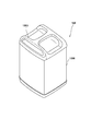
図2及び図3はモバイルバッテリユニット120の構成を示す模式図であり、図2は斜視図を示し、図3は底面図を示す。
図2及び図3はモバイルバッテリユニット120の構成を示す模式図であり、図2は斜視図を示し、図3は底面図を示す。
モバイルバッテリユニット120は、バッテリケース1200、バッテリ部1201、電極部1202、把持部1203、締結部1204、及び孔1206を含む。バッテリケース1200は、モバイルバッテリユニット120の外形を画定する略直方体の筐体であり、例えば樹脂材料で形成される。バッテリ部1201は、バッテリケース1200の内部に収容され、電動モータ121等を駆動するための電力を蓄積する。例えば、バッテリ部1201は、1又は複数のバッテリセルで構成される。電極部1202は、バッテリケース1200底面に設けられ、バッテリ部1201の電力を取り出し可能な電気接続部材(バッテリ側電気接続部材)である。電極部1202は、1以上の電極ないし端子を含む。前述のワイヤハーネス91(図1参照)の一端部は、この電極部1202に接続される。
把持部1203は、バッテリケース1200上面に設けられ、ユーザにより把持可能となっている。ユーザは、この把持部1203を用いて、モバイルバッテリユニット120を車両本体100から取り外し(それから持ち運び)、また、モバイルバッテリユニット120を車両本体100に装着し、或いは、他のモバイルバッテリユニット120に取り換えることができる。
孔1206は、電極部1202にワイヤハーネス91a,91bの電極部911a、911b(図4参照。以下、特に区別しない場合は単に「電極部911」と表現する。)を接続する際に、電極部1202に対する電極部911a、911bの位置決めを行うためのもの位置決め用の孔である。後述のガイド部材912を孔1206に挿入することにより、バッテリケース1200の底面に平行な方向についての位置決めを行うことができる。また、締結部1204は、ボルト等の締結部材によりバッテリ部1201をバッテリケース1200の底面に固定する。
図4は、車両本体100側に設けられた電極部911及びその周辺の構成示す概略図である。本実施形態の場合、支持部材914に電極支持部材915が、さらに電極支持部材915に電極部911及びガイド部材912が支持されている。
電極部911は、モバイルバッテリユニット120の電極部1202と接続可能な電動車両1側の電気接続部材(車両側電気接続部材)である。これらが接続されることにより、ワイヤハーネス91を介してバッテリ部1201に蓄電された電力が電動モータ121及び制御装置122等に供給される。電極部911は、1以上の電極ないし端子を含み、本実施形態の場合、複数の端子ピン9111が車幅方向に並んで配列されている。また、本実施形態の場合、電極部911は後述の変位ユニット180により変位自在に設けられており、モバイルバッテリユニット120が車両本体100に装着された状態において電極部911が変位することで電極部1202に接続される。
ガイド部材912は、電極部911を電極部1202に接続する際の位置決めをするための部材である。ガイド部材912が孔1206に挿入されることにより、電極部911を支持する支持部材914は、バッテリケース1200の底面に対して平行な方向への移動が制限される。これにより、電極部1202に対する電極部911の上記方向への移動が制限されるので、電極部1202に対する電極部911の位置が合わせられる。
図5は、放熱部材130の構成を示す斜視図である。放熱部材130は、モバイルバッテリユニット120の熱を放熱するための部材であり、例えばアルミニウム、鉄、銅のような伝熱性能の高い金属材料により形成される。本実施形態の場合、放熱部材130は、板形状部1301と、板形状部1301から延びる複数の放熱フィン1302とを含む。なお、複数の放熱フィン1302については、それぞれ同様の構成を有しているため図面を見やすくする関係から一部の符号を省略している(図6ないし図9についても同様)。
板形状部1301は、放熱フィン1302が設けられている面と対向する面においてモバイルバッテリユニット120に当接し、その当接部分からモバイルバッテリユニット120の熱を吸収する。なお、板形状部1301の形状は適宜設計可能である。
また、複数の放熱フィン1302は、モバイルバッテリユニット120から吸収した熱を放熱するための部材である。なお、放熱フィン1302の形状としては、周知の構成を採用可能である。例えば、蛇腹状又は剣山状の放熱フィンを用いてもよい。
また、本実施形態では、放熱部材130の板形状部1301は、傾斜部1303、回動軸1305及び平面部1306をさらに含む。これらは、放熱部材130を変位させるための構成である。後述の変位ユニット180により、放熱部材130が回動軸1305を回動中心として回動することにより、放熱部材130が変位自在に設けられる。なお、その他の構成については、<変位ユニットの構成及び作動>の項目において変位ユニット180の作動と併せて説明する。
なお、板形状部1301と複数の放熱フィン1302とは一体成型されてもよいし、それぞれ別の部材であってもよい。それぞれ別の部材である場合は、溶接、嵌合、締結その他の方法で板形状部1301と複数の放熱フィン1302とが互いに固定されてもよい。
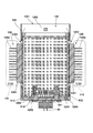
図6はモバイルバッテリユニット120が車両本体100に装着された場合のモバイルバッテリユニット120およびその周辺の構成を示す概略図であって、図1のI-I線断面図である。本実施形態では、放熱部材130及び電極部911は変位可能に構成されているが、図6は、放熱部材130がモバイルバッテリユニット120に当接した作動位置にあり、かつ、電極部911が電極部1202に接続した接続位置にある状態を示している。なお、図6は概略図であり、見易さを考慮して一部構成を省略している。
本実施形態では、モバイルバッテリユニット120は箱状の収納部125内において車両本体100に装着される。収納部125には、その上面にモバイルバッテリユニット120を着脱するため上面開口1251が設けられている。また、収納部125には、その底面に電極部911との干渉を避けるための底面開口1252が設けられ、その側面に放熱部材130との干渉を避けるための側面開口1253が設けられている。側面開口1253により、放熱部材130は、作動位置においてその少なくとも一部が収納部125の外部に配置されている。
また、収納部125の車幅方向の側面の両外側を、ダクト115によって形成された導入通路1152が通過している。このような構成により、放熱部材130は、作動位置において少なくとも一部が導入通路1152上に配置されている。本実施形態では、放熱部材の放熱フィン1302は、その全体が導入通路1152上に配置されている。これにより、より効果的にモバイルバッテリユニット120を冷却することができる。
なお、本実施形態の場合、モバイルバッテリユニット120が箱状の収納部125に収納された状態で装着されている。しかし、モバイルバッテリユニット120を車両本体100に装着する態様はこれに限られず、車両本体100がモバイルバッテリユニット120を支持可能な構成を有していればよい。
また、本実施形態では、放熱部材130が車両1の車幅方向からモバイルバッテリユニット120を挟むように当接している。これにより、車両の前方から後方へと流れる走行風の導入通路1152上に放熱部材130を容易に配置することができる。さらに、本実施形態の場合、モバイルバッテリユニット120が前後方向に並んで2つ配置されている。したがって、これらをより近接して配置することができる。しかしながら、放熱部材130が車両1の前後方向からモバイルバッテリユニット120を挟むように当接する構成も採用可能である。これにより、車幅方向にコンパクトに車両本体100を構成することができる。また、本実施形態では1つのモバイルバッテリユニット120に対して2つの放熱部材130が設けられているが、1つのモバイルバッテリユニット120に対して1つ又は3つ以上の放熱部材130を設けてもよい。
<変位ユニットの構成及び作動>
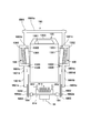
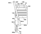
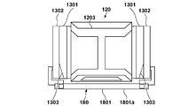
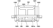
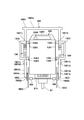
図7Aないし図7C、図8Aないし図8C及び図9Aないし図9Cは変位ユニット180の作動を示す概略図である。図7A,図8A,図9Aは車両前方からみた図、図7B,図8B,図9Bは車両右側面からみた図、図7C,図8C,図9Cは上方からみた図である。また、図7Aないし図7Cは放熱部材130が退避位置かつ電極部911が退避位置にある場合の図、図8Aないし図8Cは放熱部材130が作動位置、かつ、電極部911が接続位置と退避位置との間の位置にある場合の図である。さらに、図9Aないし図9Cは放熱部材130が作動位置かつ電極部911が接続位置にある場合の図である。なお、これらの図では、見易さを考慮して収納部125及びその他の構成を一部省略している。
図7Aないし図7C、図8Aないし図8C及び図9Aないし図9Cは変位ユニット180の作動を示す概略図である。図7A,図8A,図9Aは車両前方からみた図、図7B,図8B,図9Bは車両右側面からみた図、図7C,図8C,図9Cは上方からみた図である。また、図7Aないし図7Cは放熱部材130が退避位置かつ電極部911が退避位置にある場合の図、図8Aないし図8Cは放熱部材130が作動位置、かつ、電極部911が接続位置と退避位置との間の位置にある場合の図である。さらに、図9Aないし図9Cは放熱部材130が作動位置かつ電極部911が接続位置にある場合の図である。なお、これらの図では、見易さを考慮して収納部125及びその他の構成を一部省略している。
変位ユニット180は、放熱部材130を作動位置と退避位置との間で変位させるためのものであり、レバー1801と、アーム1802と、ガイド部材1803とを含む。変位ユニット180により放熱部材130を変位させることにより、放熱部材130をモバイルバッテリユニット120から離間させた状態でモバイルバッテリユニット120の着脱を行うことができる。変位ユニット180は、例えば車両本体100の車体フレームや収納部125に、レバー1801が回動可能な状態で支持されている。また、本実施形態では、変位ユニット180が電極部911を接続位置と退避位置との間で変位させる構成も有している。このため、変位ユニット180は、放熱部材130と電極部911とを連動して変位させることができる。
レバー1801は、ユーザが把持して回動操作するための把持部1801aと、把持部1801aの両端に接続する回動部1801bと、回動部1801bに含まれ放熱部材130を変位させる変位部1801cとを含む。把持部1801aは、モバイルバッテリユニット120が車両本体100に装着された状態で、モバイルバッテリユニット120の上方で車幅方向に延びて配置されている。また、把持部1801aの車幅方向の両端に回動部1801bがそれぞれ接続している。回動部1801bは、回動軸1801dに回動可能に支持されている。回動軸1801dは、例えば収納部125に支持される。回動部1801bに含まれる変位部1801cは、回動部1801bの回動に伴って放熱部材130の板形状部1301を車幅方向内側、すなわち、モバイルバッテリユニット120側に押すことで放熱部材130を変位させる。これにより、放熱部材130はモバイルバッテリユニット120に当接する。
アーム1802は、その一端において回動軸1801eを介してレバー1801と接続している。また、アーム1802は、上記一端と異なる端部において回動軸1802aを介して支持部材914と接続している。これにより、回動部1801bが回動すると、アーム1802が上方に引き上げられ、それに伴い支持部材914及びそれに支持された電極部911が上方に変位する。すなわち、レバー操作により、電極部911が上方に変位する。
また、ガイド部材1803は、回動部1802aの移動を規制する部材である。ガイド部材1803は、モバイルバッテリユニット120の底面に対して垂直な方向に延びるガイド溝1803aを有している。回動部1802aがガイド溝1803aに沿って変位することで、電極部911がモバイルバッテリユニット120の底面に対して垂直な方向に変位する。これにより、電極部1202に対して電極部911を接続しやすくなる。
本実施形態の場合、支持部材914は、支持部材914はフローティング機構184を介して支持されている。フローティング機構184は、支持部材914の位置をモバイルバッテリユニット120の底面に平行な方向に調整可能に支持されている。例えば、フローティング機構184は、バネ等の弾性部材の弾性力により、支持部材914に外力が働いた際にバッテリケース1200の底面に平行な方向への移動を許容しながら支持部材914を支持している。これにより、モバイルバッテリユニット120に対する支持部材914の位置の微調整が可能となる。例えば、孔1206に対するガイド部材912の位置が若干量ずれている場合、ガイド部材912は孔1206の位置に合わせて移動してから挿入される。これにより、その後接続される端子ピン9111が正確な位置に合わされる。
図7Aないし図7Cで示す放熱部材130が退避位置かつ電極部911が退避位置の状態からレバー1801を回動させると、図8Aないし図8Cで示す放熱部材130が作動位置、かつ、電極部911が接続位置と退避位置との間の位置にある状態に推移する。変位部1801cは、回動部1801の回動に伴って放熱部材130の傾斜部1303を押すことにより、放熱部材130を退避位置から作動位置に向かって変位させる。そして、さらに回動部1801が回動して変位部1801cが傾斜部1303と連続する平面部1306まで到達すると、放熱部材130は作動位置に到達してモバイルバッテリユニット120に当接する。なお、このとき、電極部911も退避位置から接続位置に向かって変位しているが、図8Aないし図8Cの時点では接続位置には到達せず両位置の間に位置している。また、図8Aないし図8Cで示す状態においては、ガイド部材912も孔1206に対して挿入されていない。
また、図8Aないし図8Cで示す状態からレバー1801をさらに回動させると、図9Aないし図9Cで示す放熱部材130が作動位置かつ電極部911が接続位置の状態に推移する。変位部1801cは、図8Aないし図8Cの状態からさらにレバー1801が回動しても平面部1306を押し続けるので、放熱部材130の位置は作動位置で維持される。一方、回動部1801の回動に伴って放熱部材130の傾斜部1303を押すことにより、放熱部材130が作動位置に向かって変位する。そして、ガイド部材912が孔1206に挿入されることにより電極部1202に対する電極部911の位置決めがなされた後に、電極部911は接続位置に到達して電極部1202と接続する。
上記のように、本実施形態では、変位ユニット180をユーザが操作すると、放熱部材130及び電極部911がそれぞれの退避位置から変位する。そして、まず放熱部材130が作動位置に到達し、その後、放熱部材130が作動位置にある状態で電極部911が接続位置に到達する。すなわち、放熱部材130がモバイルバッテリユニット120に当接された状態で電極部911が電極部1202に接続する。したがって、モバイルバッテリユニット120が2枚の放熱部材130に保持されることによりその位置が固定された状態で電極部911を電極部1202に接続できるので、より正確に電極部911の接続を行うことができる。特に、本実施形態では、放熱部材130がモバイルバッテリユニット120に当接され、モバイルバッテリユニット120の位置が固定されてからガイド部材912が孔1206に挿入されるので、より精度よく位置決めを行うことができる。
また、本実施形態の場合、モバイルバッテリユニット120を冷却するための放熱部材130等の構成が車両本体100側に設けられている。したがって、持ち運びする必要のあるモバイルバッテリユニット120側に冷却するための構成を設ける必要がないので、モバイルバッテリユニット120側の重量の増加を抑制しつつモバイルバッテリユニット120を冷却することができる。さらに、モバイルバッテリユニット120側に冷却するための構成を設ける必要がないので、その分バッテリ容量を大きくすることができる。
本実施形態では、変位ユニット180は、放熱部材130と電極部911とを連動して変位させている。しかしながら、上記構成は例示であり他の構成も採用可能である。例えば、放熱部材130及び電極部911に対してそれぞれを独立に変位可能な構成を設けてもよい。また、本実施形態では機械的な構成で放熱部材130及び電極部911を変位させているが、電動又は油圧アクチュエータ等により変位させてもよいし、機械的な構成とこれらを組み合わせてもよい。例えば、電極部911を変位ユニット180により機械的に変位させ、放熱部材130を油圧アクチュエータで変位させてもよい。このとき、変位ユニット180のレバー1801回動を契機に油圧アクチュエータを作動せることで電極部911の変位と放熱部材130の変位とを連動させてもよい。
<実施形態のまとめ>
上記実施形態は以下の電動車両を少なくとも開示する。
上記実施形態は以下の電動車両を少なくとも開示する。
1.上記実施形態の電動車両(例えば1)は、
車両本体(例えば100)と、該車両本体に着脱自在に装着されるバッテリユニット(例えば120)と、を備えた電動車両であって、
前記車両本体は、
前記バッテリユニットに当接する第1位置と、前記バッテリユニットから離間した第2位置との間で変位自在に設けられ、前記バッテリユニットの熱を放熱する放熱部材を備える。
車両本体(例えば100)と、該車両本体に着脱自在に装着されるバッテリユニット(例えば120)と、を備えた電動車両であって、
前記車両本体は、
前記バッテリユニットに当接する第1位置と、前記バッテリユニットから離間した第2位置との間で変位自在に設けられ、前記バッテリユニットの熱を放熱する放熱部材を備える。
この実施形態によれば、着脱自在なバッテリユニットに対して放熱部材を当接できるので、より効果的にバッテリユニットを冷却することができる。また、車両本体側にバッテリユニットを冷却する構成が設けられるので、バッテリユニットの重量の増加を抑制することができる。
2.上記実施形態では、
前記放熱部材を前記第1位置と前記第2位置との間で変位させる変位手段をさらに備える。
前記放熱部材を前記第1位置と前記第2位置との間で変位させる変位手段をさらに備える。
この実施形態によれば、放熱部材を変位させることができるので、放熱部材をバッテリユニットから離間させた状態でバッテリユニットの着脱を行うことができる。
3.上記実施形態では、
前記バッテリユニットは、バッテリセルと、該バッテリセルに蓄電された電力を取り出し可能なバッテリ側電気接続部材と、を備え、
前記車両本体は、前記バッテリ側電気接続部材に接続可能な車両側電気接続部材を備え、
該車両側電気接続部材は、前記放熱部材が前記第1位置に位置している状態で前記バッテリ側電気接続部材に接続される。
前記バッテリユニットは、バッテリセルと、該バッテリセルに蓄電された電力を取り出し可能なバッテリ側電気接続部材と、を備え、
前記車両本体は、前記バッテリ側電気接続部材に接続可能な車両側電気接続部材を備え、
該車両側電気接続部材は、前記放熱部材が前記第1位置に位置している状態で前記バッテリ側電気接続部材に接続される。
この実施形態によれば、バッテリユニットに放熱部材が当接し、バッテリユニットの位置が固定された状態で車両側電気接続部材をバッテリ側電気接続部材に接続することができる。したがって、電気接続部材の接続時にバッテリユニットの位置ずれを防ぐことができる。
4.上記実施形態では、
前記車両側電気接続部材は、
前記バッテリ側電気接続部材に接続する第3位置、及び、前記バッテリ側電気接続部材から離間した第4位置の間で変位自在に設けられ、
前記バッテリユニットが前記車両本体に装着された状態で前記第4位置から前記第3位置へ変位することにより、前記バッテリ側電気接続部材と接続する。
前記車両側電気接続部材は、
前記バッテリ側電気接続部材に接続する第3位置、及び、前記バッテリ側電気接続部材から離間した第4位置の間で変位自在に設けられ、
前記バッテリユニットが前記車両本体に装着された状態で前記第4位置から前記第3位置へ変位することにより、前記バッテリ側電気接続部材と接続する。
この実施形態によれば、バッテリユニットが車両本体に装着された状態で車両側電気接続部材をバッテリユニットに接続することができる。
5.上記実施形態では、
前記バッテリユニットは、位置決め孔を有し
前記車両本体は、位置決め部材を有し、
前記位置決め孔に前記位置決め部材が挿入されることにより、前記バッテリ側電気接続部材に対する前記車両側電気接続部材の位置が合わせられる。
前記バッテリユニットは、位置決め孔を有し
前記車両本体は、位置決め部材を有し、
前記位置決め孔に前記位置決め部材が挿入されることにより、前記バッテリ側電気接続部材に対する前記車両側電気接続部材の位置が合わせられる。
この実施形態によれば、位置決め部材によりバッテリ側電気接続部材に対する車両側電気接続部材の位置が規制されるので、より正確に車両側電気接続部材をバッテリ側電気接続部材に接続することができる。
6.上記実施形態では、
前記車両側電気接続部材及び前記位置決め部材は、フローティング機構により前記バッテリユニットに対する位置を調整可能に設けられる。
前記車両側電気接続部材及び前記位置決め部材は、フローティング機構により前記バッテリユニットに対する位置を調整可能に設けられる。
この実施形態によれば、フローティング機構により調整を行いながら車両側電気接続部材の位置決めを行うことができる。
7.上記実施形態では、
前記車両側電気接続部材は、前記変位手段により前記第3位置と前記第4位置との間で変位することを特徴とする。
前記車両側電気接続部材は、前記変位手段により前記第3位置と前記第4位置との間で変位することを特徴とする。
この実施形態によれば、放熱部材の変位と車両側電気接続部材の変位を連動させて行うことができる。
8.上記実施形態では、
前記電動車両は、2つの前記放熱部材を備え、前記電動車両の車幅方向から前記バッテリユニットを挟むように前記バッテリユニットに当接する。
前記電動車両は、2つの前記放熱部材を備え、前記電動車両の車幅方向から前記バッテリユニットを挟むように前記バッテリユニットに当接する。
この実施形態によれば、走行風の通過しやすい車幅方向外側に放熱部材が配置されるため、より効果的にバッテリユニットを冷却することができる。
9.上記実施形態では、
前記電動車両は、2つの前記放熱部材を備え、前記電動車両の前後方向から前記バッテリユニットを挟むように前記バッテリユニットに当接することを特徴とする。
前記電動車両は、2つの前記放熱部材を備え、前記電動車両の前後方向から前記バッテリユニットを挟むように前記バッテリユニットに当接することを特徴とする。
この実施形態によれば、車幅方向にコンパクトに放熱部材を配置することができる。
10.上記実施形態では、
前記放熱部材は、前記バッテリユニットに当接する板形状部と、該板形状部から延びる放熱フィンと、を含む。
前記放熱部材は、前記バッテリユニットに当接する板形状部と、該板形状部から延びる放熱フィンと、を含む。
この実施形態によれば、放熱フィンにより放熱部材の表面積が増加し、より効果的にバッテリユニットを冷却することができる。
11.上記実施形態では、
前記車両本体は、走行風を導入する導入通路を形成するダクトを備え、
前記放熱部材が前記第1位置に位置している場合、前記放熱フィンの少なくとも一部が前記導入通路に配置される。
前記車両本体は、走行風を導入する導入通路を形成するダクトを備え、
前記放熱部材が前記第1位置に位置している場合、前記放熱フィンの少なくとも一部が前記導入通路に配置される。
この実施形態によれば、走行風を放熱部材に当てることでより効果的にバッテリユニットを冷却することができる。
本発明は上記の実施形態に制限されるものではなく、本発明の要旨の範囲内で、種々の変形・変更が可能である。
Claims (11)
- 車両本体と、該車両本体に着脱自在に装着されるバッテリユニットと、を備えた電動車両であって、
前記車両本体は、
前記バッテリユニットに当接する第1位置と、前記バッテリユニットから離間した第2位置との間で変位自在に設けられ、前記バッテリユニットの熱を放熱する放熱部材を備える、
ことを特徴とする電動車両。 - 前記放熱部材を前記第1位置と前記第2位置との間で変位させる変位手段をさらに備えることを特徴とする請求項1に記載の電動車両。
- 前記バッテリユニットは、バッテリセルと、該バッテリセルに蓄電された電力を取り出し可能なバッテリ側電気接続部材と、を備え、
前記車両本体は、前記バッテリ側電気接続部材に接続可能な車両側電気接続部材を備え、
該車両側電気接続部材は、前記放熱部材が前記第1位置に位置している状態で前記バッテリ側電気接続部材に接続される、
ことを特徴とする請求項2に記載の電動車両。 - 前記車両側電気接続部材は、
前記バッテリ側電気接続部材に接続する第3位置、及び、前記バッテリ側電気接続部材から離間した第4位置の間で変位自在に設けられ、
前記バッテリユニットが前記車両本体に装着された状態で前記第4位置から前記第3位置へ変位することにより、前記バッテリ側電気接続部材と接続することを特徴とする請求項3に記載の電動車両。 - 前記バッテリユニットは、位置決め孔を有し
前記車両本体は、位置決め部材を有し、
前記位置決め孔に前記位置決め部材が挿入されることにより、前記バッテリ側電気接続部材に対する前記車両側電気接続部材の位置が合わせられる、
ことを特徴とする請求項4に記載の電動車両。 - 前記車両側電気接続部材及び前記位置決め部材は、フローティング機構により前記バッテリユニットに対する位置を調整可能に設けられることを特徴とする請求項5に記載の電動車両。
- 前記車両側電気接続部材は、前記変位手段により前記第3位置と前記第4位置との間で変位することを特徴とする請求項4ないし6のいずれか1項に記載の電動車両。
- 前記電動車両は、2つの前記放熱部材を備え、前記電動車両の車幅方向から前記バッテリユニットを挟むように前記バッテリユニットに当接することを特徴とする請求項1ないし7のいずれか1項に記載の電動車両。
- 前記電動車両は、2つの前記放熱部材を備え、前記電動車両の前後方向から前記バッテリユニットを挟むように前記バッテリユニットに当接することを特徴とする請求項1ないし7のいずれか1項に記載の電動車両。
- 前記放熱部材は、前記バッテリユニットに当接する板形状部と、該板形状部から延びる放熱フィンと、を含むことを特徴とする請求項1ないし9のいずれか1項に記載の電動車両。
- 前記車両本体は、走行風を導入する導入通路を形成するダクトを備え、
前記放熱部材が前記第1位置に位置している場合、前記放熱フィンの少なくとも一部が前記導入通路に配置される、
ことを特徴とする請求項10に記載の電動車両。
Priority Applications (2)
| Application Number | Priority Date | Filing Date | Title |
|---|---|---|---|
| CN201980090210.5A CN113365865A (zh) | 2019-02-05 | 2019-11-05 | 电动车辆 |
| JP2020570367A JP7164634B2 (ja) | 2019-02-05 | 2019-11-05 | 電動車両 |
Applications Claiming Priority (2)
| Application Number | Priority Date | Filing Date | Title |
|---|---|---|---|
| JP2019018827 | 2019-02-05 | ||
| JP2019-018827 | 2019-02-05 |
Publications (1)
| Publication Number | Publication Date |
|---|---|
| WO2020161970A1 true WO2020161970A1 (ja) | 2020-08-13 |
Family
ID=71947546
Family Applications (1)
| Application Number | Title | Priority Date | Filing Date |
|---|---|---|---|
| PCT/JP2019/043184 Ceased WO2020161970A1 (ja) | 2019-02-05 | 2019-11-05 | 電動車両 |
Country Status (3)
| Country | Link |
|---|---|
| JP (1) | JP7164634B2 (ja) |
| CN (1) | CN113365865A (ja) |
| WO (1) | WO2020161970A1 (ja) |
Cited By (1)
| Publication number | Priority date | Publication date | Assignee | Title |
|---|---|---|---|---|
| JP2024176897A (ja) * | 2023-06-09 | 2024-12-19 | 本田技研工業株式会社 | バッテリパック |
Citations (4)
| Publication number | Priority date | Publication date | Assignee | Title |
|---|---|---|---|---|
| JPH11129959A (ja) * | 1997-11-04 | 1999-05-18 | Honda Motor Co Ltd | 電動補助車両 |
| JP2013164969A (ja) * | 2012-02-10 | 2013-08-22 | Yamaha Motor Co Ltd | バッテリモジュールおよび鞍乗型電動車両 |
| JP2013208935A (ja) * | 2012-03-30 | 2013-10-10 | Honda Motor Co Ltd | 電動車両 |
| JP2017137002A (ja) * | 2016-02-04 | 2017-08-10 | 本田技研工業株式会社 | 電動車両のバッテリ搭載構造 |
Family Cites Families (4)
| Publication number | Priority date | Publication date | Assignee | Title |
|---|---|---|---|---|
| JP2000323186A (ja) * | 1999-05-07 | 2000-11-24 | Sanyo Electric Co Ltd | 電子機器のバッテリー装置 |
| JP2004111370A (ja) * | 2002-08-29 | 2004-04-08 | Matsushita Electric Ind Co Ltd | 電池の熱制御装置 |
| JP2008135191A (ja) * | 2006-10-23 | 2008-06-12 | Toyota Motor Corp | 冷却装置及び車両 |
| WO2018194296A1 (ko) * | 2017-04-18 | 2018-10-25 | 주식회사 엘지화학 | 배터리 모듈 |
-
2019
- 2019-11-05 CN CN201980090210.5A patent/CN113365865A/zh active Pending
- 2019-11-05 WO PCT/JP2019/043184 patent/WO2020161970A1/ja not_active Ceased
- 2019-11-05 JP JP2020570367A patent/JP7164634B2/ja active Active
Patent Citations (4)
| Publication number | Priority date | Publication date | Assignee | Title |
|---|---|---|---|---|
| JPH11129959A (ja) * | 1997-11-04 | 1999-05-18 | Honda Motor Co Ltd | 電動補助車両 |
| JP2013164969A (ja) * | 2012-02-10 | 2013-08-22 | Yamaha Motor Co Ltd | バッテリモジュールおよび鞍乗型電動車両 |
| JP2013208935A (ja) * | 2012-03-30 | 2013-10-10 | Honda Motor Co Ltd | 電動車両 |
| JP2017137002A (ja) * | 2016-02-04 | 2017-08-10 | 本田技研工業株式会社 | 電動車両のバッテリ搭載構造 |
Non-Patent Citations (2)
| Title |
|---|
| "PCX ELECTRIC Product Manual", HONDA MOTOR CO., LTD., November 2018 (2018-11-01), pages 2,4 - 6,13 * |
| MITSUKAWA, MAKOTO ET AL.: "Development of the PCX ELECTRIC", HONDA R&D TECHNICAL REVIEW, vol. 31, no. 1, April 2019 (2019-04-01), pages 48 - 61 * |
Cited By (1)
| Publication number | Priority date | Publication date | Assignee | Title |
|---|---|---|---|---|
| JP2024176897A (ja) * | 2023-06-09 | 2024-12-19 | 本田技研工業株式会社 | バッテリパック |
Also Published As
| Publication number | Publication date |
|---|---|
| JPWO2020161970A1 (ja) | 2020-08-13 |
| CN113365865A (zh) | 2021-09-07 |
| JP7164634B2 (ja) | 2022-11-01 |
Similar Documents
| Publication | Publication Date | Title |
|---|---|---|
| US9327586B2 (en) | Saddle-type electric vehicle | |
| US9346421B2 (en) | Saddle-type electric vehicle | |
| US10611425B2 (en) | Saddle-type electric vehicle | |
| US9545968B2 (en) | Saddle-type electric vehicle | |
| US9660236B2 (en) | Battery and saddle-type electric vehicle equipped therewith | |
| CN102556239B (zh) | 跨骑型电动车辆 | |
| JP6971386B2 (ja) | 電動車両 | |
| JP6950081B2 (ja) | 電動車両 | |
| US20120111651A1 (en) | Saddle-type electric vehicle | |
| WO2019044291A1 (ja) | 電動車両 | |
| CN102464071A (zh) | 电动车辆 | |
| CN113365907B (zh) | 跨骑型电动车辆 | |
| WO2017022394A1 (ja) | 電動車両 | |
| US12218371B2 (en) | Battery housing apparatus and electric vehicle | |
| JP7164634B2 (ja) | 電動車両 | |
| JP7165757B2 (ja) | 電動車両及びバッテリユニット | |
| JP5492742B2 (ja) | 鞍乗り型電動車両の冷却ダクト配索構造 | |
| JP2014051289A (ja) | 電動二輪車 | |
| CN112262071A (zh) | 电动车辆 | |
| WO2020188752A1 (ja) | バッテリ収納装置、および電動車両 | |
| JP2012101567A (ja) | 鞍乗型電動車両 | |
| CN120024435A (zh) | 跨骑型电动车辆 | |
| WO2024058269A1 (ja) | スクータ型電動車両 | |
| WO2023127108A1 (ja) | 鞍乗り型車両 |
Legal Events
| Date | Code | Title | Description |
|---|---|---|---|
| 121 | Ep: the epo has been informed by wipo that ep was designated in this application |
Ref document number: 19914201 Country of ref document: EP Kind code of ref document: A1 |
|
| ENP | Entry into the national phase |
Ref document number: 2020570367 Country of ref document: JP Kind code of ref document: A |
|
| NENP | Non-entry into the national phase |
Ref country code: DE |
|
| 122 | Ep: pct application non-entry in european phase |
Ref document number: 19914201 Country of ref document: EP Kind code of ref document: A1 |