WO2020158920A1 - Dispositif et procédé de production d'un récipient en résine - Google Patents
Dispositif et procédé de production d'un récipient en résine Download PDFInfo
- Publication number
- WO2020158920A1 WO2020158920A1 PCT/JP2020/003653 JP2020003653W WO2020158920A1 WO 2020158920 A1 WO2020158920 A1 WO 2020158920A1 JP 2020003653 W JP2020003653 W JP 2020003653W WO 2020158920 A1 WO2020158920 A1 WO 2020158920A1
- Authority
- WO
- WIPO (PCT)
- Prior art keywords
- temperature
- preform
- injection
- molding
- injection molding
- Prior art date
Links
- 238000004519 manufacturing process Methods 0.000 title claims abstract description 45
- 229920005989 resin Polymers 0.000 title claims abstract description 34
- 239000011347 resin Substances 0.000 title claims abstract description 34
- 238000001746 injection moulding Methods 0.000 claims abstract description 131
- 238000000071 blow moulding Methods 0.000 claims abstract description 119
- 238000000465 moulding Methods 0.000 claims abstract description 28
- 230000007423 decrease Effects 0.000 claims abstract description 5
- 238000001816 cooling Methods 0.000 claims description 69
- 238000000034 method Methods 0.000 claims description 51
- 239000000463 material Substances 0.000 claims description 21
- 230000009477 glass transition Effects 0.000 claims description 16
- 238000010102 injection blow moulding Methods 0.000 abstract 1
- 238000009826 distribution Methods 0.000 description 46
- 239000003570 air Substances 0.000 description 45
- 239000010410 layer Substances 0.000 description 43
- 238000002347 injection Methods 0.000 description 39
- 239000007924 injection Substances 0.000 description 39
- 238000003860 storage Methods 0.000 description 21
- 238000003303 reheating Methods 0.000 description 15
- 229920000139 polyethylene terephthalate Polymers 0.000 description 14
- 239000005020 polyethylene terephthalate Substances 0.000 description 14
- 238000012546 transfer Methods 0.000 description 12
- 238000010438 heat treatment Methods 0.000 description 11
- 238000007796 conventional method Methods 0.000 description 10
- 238000002791 soaking Methods 0.000 description 10
- 238000007664 blowing Methods 0.000 description 9
- 238000000605 extraction Methods 0.000 description 7
- 238000013461 design Methods 0.000 description 6
- 230000000704 physical effect Effects 0.000 description 6
- -1 polyethylene terephthalate Polymers 0.000 description 6
- 239000002344 surface layer Substances 0.000 description 6
- 229920003002 synthetic resin Polymers 0.000 description 6
- 239000000057 synthetic resin Substances 0.000 description 6
- 239000012792 core layer Substances 0.000 description 5
- 238000011049 filling Methods 0.000 description 4
- 238000004904 shortening Methods 0.000 description 4
- 238000002425 crystallisation Methods 0.000 description 3
- 230000008025 crystallization Effects 0.000 description 3
- 238000010586 diagram Methods 0.000 description 3
- 238000002844 melting Methods 0.000 description 3
- 230000008018 melting Effects 0.000 description 3
- 230000000717 retained effect Effects 0.000 description 3
- 229920001169 thermoplastic Polymers 0.000 description 3
- 229920005992 thermoplastic resin Polymers 0.000 description 3
- 239000004416 thermosoftening plastic Substances 0.000 description 3
- 230000002087 whitening effect Effects 0.000 description 3
- 239000004698 Polyethylene Substances 0.000 description 2
- 239000004743 Polypropylene Substances 0.000 description 2
- 238000013459 approach Methods 0.000 description 2
- 238000007599 discharging Methods 0.000 description 2
- 230000000694 effects Effects 0.000 description 2
- 238000011067 equilibration Methods 0.000 description 2
- 230000002093 peripheral effect Effects 0.000 description 2
- 229920003207 poly(ethylene-2,6-naphthalate) Polymers 0.000 description 2
- 239000004417 polycarbonate Substances 0.000 description 2
- 239000011112 polyethylene naphthalate Substances 0.000 description 2
- 238000012545 processing Methods 0.000 description 2
- 230000000087 stabilizing effect Effects 0.000 description 2
- 238000010792 warming Methods 0.000 description 2
- 241000251468 Actinopterygii Species 0.000 description 1
- 239000012080 ambient air Substances 0.000 description 1
- FFBHFFJDDLITSX-UHFFFAOYSA-N benzyl N-[2-hydroxy-4-(3-oxomorpholin-4-yl)phenyl]carbamate Chemical compound OC1=C(NC(=O)OCC2=CC=CC=C2)C=CC(=C1)N1CCOCC1=O FFBHFFJDDLITSX-UHFFFAOYSA-N 0.000 description 1
- 230000015572 biosynthetic process Effects 0.000 description 1
- 239000002826 coolant Substances 0.000 description 1
- 230000003247 decreasing effect Effects 0.000 description 1
- 230000007547 defect Effects 0.000 description 1
- 230000002950 deficient Effects 0.000 description 1
- 238000005516 engineering process Methods 0.000 description 1
- 230000002349 favourable effect Effects 0.000 description 1
- 239000012467 final product Substances 0.000 description 1
- 230000001976 improved effect Effects 0.000 description 1
- 230000001939 inductive effect Effects 0.000 description 1
- 239000000155 melt Substances 0.000 description 1
- 229920001420 poly(caprolactone-co-lactic acid) Polymers 0.000 description 1
- 229920000515 polycarbonate Polymers 0.000 description 1
- 229920001123 polycyclohexylenedimethylene terephthalate Polymers 0.000 description 1
- 229920001225 polyester resin Polymers 0.000 description 1
- 239000004645 polyester resin Substances 0.000 description 1
- 229920000573 polyethylene Polymers 0.000 description 1
- 229920001155 polypropylene Polymers 0.000 description 1
- 239000000047 product Substances 0.000 description 1
- 230000001737 promoting effect Effects 0.000 description 1
- 239000003507 refrigerant Substances 0.000 description 1
- 238000007493 shaping process Methods 0.000 description 1
- 230000003746 surface roughness Effects 0.000 description 1
Images


Classifications
-
- B—PERFORMING OPERATIONS; TRANSPORTING
- B29—WORKING OF PLASTICS; WORKING OF SUBSTANCES IN A PLASTIC STATE IN GENERAL
- B29C—SHAPING OR JOINING OF PLASTICS; SHAPING OF MATERIAL IN A PLASTIC STATE, NOT OTHERWISE PROVIDED FOR; AFTER-TREATMENT OF THE SHAPED PRODUCTS, e.g. REPAIRING
- B29C49/00—Blow-moulding, i.e. blowing a preform or parison to a desired shape within a mould; Apparatus therefor
- B29C49/42—Component parts, details or accessories; Auxiliary operations
- B29C49/64—Heating or cooling preforms, parisons or blown articles
- B29C49/6409—Thermal conditioning of preforms
- B29C49/6427—Cooling of preforms
-
- B—PERFORMING OPERATIONS; TRANSPORTING
- B29—WORKING OF PLASTICS; WORKING OF SUBSTANCES IN A PLASTIC STATE IN GENERAL
- B29B—PREPARATION OR PRETREATMENT OF THE MATERIAL TO BE SHAPED; MAKING GRANULES OR PREFORMS; RECOVERY OF PLASTICS OR OTHER CONSTITUENTS OF WASTE MATERIAL CONTAINING PLASTICS
- B29B11/00—Making preforms
- B29B11/06—Making preforms by moulding the material
- B29B11/08—Injection moulding
-
- B—PERFORMING OPERATIONS; TRANSPORTING
- B29—WORKING OF PLASTICS; WORKING OF SUBSTANCES IN A PLASTIC STATE IN GENERAL
- B29C—SHAPING OR JOINING OF PLASTICS; SHAPING OF MATERIAL IN A PLASTIC STATE, NOT OTHERWISE PROVIDED FOR; AFTER-TREATMENT OF THE SHAPED PRODUCTS, e.g. REPAIRING
- B29C45/00—Injection moulding, i.e. forcing the required volume of moulding material through a nozzle into a closed mould; Apparatus therefor
- B29C45/17—Component parts, details or accessories; Auxiliary operations
- B29C45/72—Heating or cooling
- B29C45/7207—Heating or cooling of the moulded articles
-
- B—PERFORMING OPERATIONS; TRANSPORTING
- B29—WORKING OF PLASTICS; WORKING OF SUBSTANCES IN A PLASTIC STATE IN GENERAL
- B29C—SHAPING OR JOINING OF PLASTICS; SHAPING OF MATERIAL IN A PLASTIC STATE, NOT OTHERWISE PROVIDED FOR; AFTER-TREATMENT OF THE SHAPED PRODUCTS, e.g. REPAIRING
- B29C49/00—Blow-moulding, i.e. blowing a preform or parison to a desired shape within a mould; Apparatus therefor
- B29C49/02—Combined blow-moulding and manufacture of the preform or the parison
- B29C49/06—Injection blow-moulding
- B29C49/061—Injection blow-moulding with parison holding means displaceable between injection and blow stations
- B29C49/062—Injection blow-moulding with parison holding means displaceable between injection and blow stations following an arcuate path, e.g. rotary or oscillating-type
-
- B—PERFORMING OPERATIONS; TRANSPORTING
- B29—WORKING OF PLASTICS; WORKING OF SUBSTANCES IN A PLASTIC STATE IN GENERAL
- B29C—SHAPING OR JOINING OF PLASTICS; SHAPING OF MATERIAL IN A PLASTIC STATE, NOT OTHERWISE PROVIDED FOR; AFTER-TREATMENT OF THE SHAPED PRODUCTS, e.g. REPAIRING
- B29C49/00—Blow-moulding, i.e. blowing a preform or parison to a desired shape within a mould; Apparatus therefor
- B29C49/28—Blow-moulding apparatus
-
- B—PERFORMING OPERATIONS; TRANSPORTING
- B29—WORKING OF PLASTICS; WORKING OF SUBSTANCES IN A PLASTIC STATE IN GENERAL
- B29C—SHAPING OR JOINING OF PLASTICS; SHAPING OF MATERIAL IN A PLASTIC STATE, NOT OTHERWISE PROVIDED FOR; AFTER-TREATMENT OF THE SHAPED PRODUCTS, e.g. REPAIRING
- B29C49/00—Blow-moulding, i.e. blowing a preform or parison to a desired shape within a mould; Apparatus therefor
- B29C49/42—Component parts, details or accessories; Auxiliary operations
- B29C49/64—Heating or cooling preforms, parisons or blown articles
- B29C49/6409—Thermal conditioning of preforms
- B29C49/6436—Thermal conditioning of preforms characterised by temperature differential
- B29C49/6454—Thermal conditioning of preforms characterised by temperature differential through the preform thickness
-
- B—PERFORMING OPERATIONS; TRANSPORTING
- B29—WORKING OF PLASTICS; WORKING OF SUBSTANCES IN A PLASTIC STATE IN GENERAL
- B29C—SHAPING OR JOINING OF PLASTICS; SHAPING OF MATERIAL IN A PLASTIC STATE, NOT OTHERWISE PROVIDED FOR; AFTER-TREATMENT OF THE SHAPED PRODUCTS, e.g. REPAIRING
- B29C49/00—Blow-moulding, i.e. blowing a preform or parison to a desired shape within a mould; Apparatus therefor
- B29C49/42—Component parts, details or accessories; Auxiliary operations
- B29C49/64—Heating or cooling preforms, parisons or blown articles
- B29C49/6409—Thermal conditioning of preforms
- B29C49/6463—Thermal conditioning of preforms by contact heating or cooling, e.g. mandrels or cores specially adapted for heating or cooling preforms
-
- B—PERFORMING OPERATIONS; TRANSPORTING
- B29—WORKING OF PLASTICS; WORKING OF SUBSTANCES IN A PLASTIC STATE IN GENERAL
- B29C—SHAPING OR JOINING OF PLASTICS; SHAPING OF MATERIAL IN A PLASTIC STATE, NOT OTHERWISE PROVIDED FOR; AFTER-TREATMENT OF THE SHAPED PRODUCTS, e.g. REPAIRING
- B29C49/00—Blow-moulding, i.e. blowing a preform or parison to a desired shape within a mould; Apparatus therefor
- B29C49/02—Combined blow-moulding and manufacture of the preform or the parison
- B29C2049/023—Combined blow-moulding and manufacture of the preform or the parison using inherent heat of the preform, i.e. 1 step blow moulding
-
- B—PERFORMING OPERATIONS; TRANSPORTING
- B29—WORKING OF PLASTICS; WORKING OF SUBSTANCES IN A PLASTIC STATE IN GENERAL
- B29C—SHAPING OR JOINING OF PLASTICS; SHAPING OF MATERIAL IN A PLASTIC STATE, NOT OTHERWISE PROVIDED FOR; AFTER-TREATMENT OF THE SHAPED PRODUCTS, e.g. REPAIRING
- B29C2949/00—Indexing scheme relating to blow-moulding
- B29C2949/07—Preforms or parisons characterised by their configuration
- B29C2949/076—Preforms or parisons characterised by their configuration characterised by the shape
- B29C2949/0768—Preforms or parisons characterised by their configuration characterised by the shape characterised by the shape of specific parts of preform
- B29C2949/077—Preforms or parisons characterised by their configuration characterised by the shape characterised by the shape of specific parts of preform characterised by the neck
- B29C2949/0771—Wide-mouth
-
- B—PERFORMING OPERATIONS; TRANSPORTING
- B29—WORKING OF PLASTICS; WORKING OF SUBSTANCES IN A PLASTIC STATE IN GENERAL
- B29C—SHAPING OR JOINING OF PLASTICS; SHAPING OF MATERIAL IN A PLASTIC STATE, NOT OTHERWISE PROVIDED FOR; AFTER-TREATMENT OF THE SHAPED PRODUCTS, e.g. REPAIRING
- B29C2949/00—Indexing scheme relating to blow-moulding
- B29C2949/07—Preforms or parisons characterised by their configuration
- B29C2949/081—Specified dimensions, e.g. values or ranges
- B29C2949/0811—Wall thickness
-
- B—PERFORMING OPERATIONS; TRANSPORTING
- B29—WORKING OF PLASTICS; WORKING OF SUBSTANCES IN A PLASTIC STATE IN GENERAL
- B29C—SHAPING OR JOINING OF PLASTICS; SHAPING OF MATERIAL IN A PLASTIC STATE, NOT OTHERWISE PROVIDED FOR; AFTER-TREATMENT OF THE SHAPED PRODUCTS, e.g. REPAIRING
- B29C49/00—Blow-moulding, i.e. blowing a preform or parison to a desired shape within a mould; Apparatus therefor
- B29C49/42—Component parts, details or accessories; Auxiliary operations
- B29C49/4242—Means for deforming the parison prior to the blowing operation
- B29C49/42421—Means for deforming the parison prior to the blowing operation before laying into the mould
-
- B—PERFORMING OPERATIONS; TRANSPORTING
- B29—WORKING OF PLASTICS; WORKING OF SUBSTANCES IN A PLASTIC STATE IN GENERAL
- B29C—SHAPING OR JOINING OF PLASTICS; SHAPING OF MATERIAL IN A PLASTIC STATE, NOT OTHERWISE PROVIDED FOR; AFTER-TREATMENT OF THE SHAPED PRODUCTS, e.g. REPAIRING
- B29C49/00—Blow-moulding, i.e. blowing a preform or parison to a desired shape within a mould; Apparatus therefor
- B29C49/42—Component parts, details or accessories; Auxiliary operations
- B29C49/64—Heating or cooling preforms, parisons or blown articles
- B29C49/6409—Thermal conditioning of preforms
- B29C49/6463—Thermal conditioning of preforms by contact heating or cooling, e.g. mandrels or cores specially adapted for heating or cooling preforms
- B29C49/6465—Cooling
-
- B—PERFORMING OPERATIONS; TRANSPORTING
- B29—WORKING OF PLASTICS; WORKING OF SUBSTANCES IN A PLASTIC STATE IN GENERAL
- B29C—SHAPING OR JOINING OF PLASTICS; SHAPING OF MATERIAL IN A PLASTIC STATE, NOT OTHERWISE PROVIDED FOR; AFTER-TREATMENT OF THE SHAPED PRODUCTS, e.g. REPAIRING
- B29C49/00—Blow-moulding, i.e. blowing a preform or parison to a desired shape within a mould; Apparatus therefor
- B29C49/42—Component parts, details or accessories; Auxiliary operations
- B29C49/64—Heating or cooling preforms, parisons or blown articles
- B29C49/6409—Thermal conditioning of preforms
- B29C49/6463—Thermal conditioning of preforms by contact heating or cooling, e.g. mandrels or cores specially adapted for heating or cooling preforms
- B29C49/6466—Thermal conditioning of preforms by contact heating or cooling, e.g. mandrels or cores specially adapted for heating or cooling preforms on the inside
-
- B—PERFORMING OPERATIONS; TRANSPORTING
- B29—WORKING OF PLASTICS; WORKING OF SUBSTANCES IN A PLASTIC STATE IN GENERAL
- B29C—SHAPING OR JOINING OF PLASTICS; SHAPING OF MATERIAL IN A PLASTIC STATE, NOT OTHERWISE PROVIDED FOR; AFTER-TREATMENT OF THE SHAPED PRODUCTS, e.g. REPAIRING
- B29C49/00—Blow-moulding, i.e. blowing a preform or parison to a desired shape within a mould; Apparatus therefor
- B29C49/42—Component parts, details or accessories; Auxiliary operations
- B29C49/64—Heating or cooling preforms, parisons or blown articles
- B29C49/6409—Thermal conditioning of preforms
- B29C49/6463—Thermal conditioning of preforms by contact heating or cooling, e.g. mandrels or cores specially adapted for heating or cooling preforms
- B29C49/6467—Thermal conditioning of preforms by contact heating or cooling, e.g. mandrels or cores specially adapted for heating or cooling preforms on the outside
-
- B—PERFORMING OPERATIONS; TRANSPORTING
- B29—WORKING OF PLASTICS; WORKING OF SUBSTANCES IN A PLASTIC STATE IN GENERAL
- B29C—SHAPING OR JOINING OF PLASTICS; SHAPING OF MATERIAL IN A PLASTIC STATE, NOT OTHERWISE PROVIDED FOR; AFTER-TREATMENT OF THE SHAPED PRODUCTS, e.g. REPAIRING
- B29C49/00—Blow-moulding, i.e. blowing a preform or parison to a desired shape within a mould; Apparatus therefor
- B29C49/42—Component parts, details or accessories; Auxiliary operations
- B29C49/78—Measuring, controlling or regulating
- B29C49/786—Temperature
-
- B—PERFORMING OPERATIONS; TRANSPORTING
- B29—WORKING OF PLASTICS; WORKING OF SUBSTANCES IN A PLASTIC STATE IN GENERAL
- B29K—INDEXING SCHEME ASSOCIATED WITH SUBCLASSES B29B, B29C OR B29D, RELATING TO MOULDING MATERIALS OR TO MATERIALS FOR MOULDS, REINFORCEMENTS, FILLERS OR PREFORMED PARTS, e.g. INSERTS
- B29K2067/00—Use of polyesters or derivatives thereof, as moulding material
- B29K2067/003—PET, i.e. poylethylene terephthalate
-
- B—PERFORMING OPERATIONS; TRANSPORTING
- B29—WORKING OF PLASTICS; WORKING OF SUBSTANCES IN A PLASTIC STATE IN GENERAL
- B29K—INDEXING SCHEME ASSOCIATED WITH SUBCLASSES B29B, B29C OR B29D, RELATING TO MOULDING MATERIALS OR TO MATERIALS FOR MOULDS, REINFORCEMENTS, FILLERS OR PREFORMED PARTS, e.g. INSERTS
- B29K2105/00—Condition, form or state of moulded material or of the material to be shaped
- B29K2105/25—Solid
- B29K2105/253—Preform
-
- B—PERFORMING OPERATIONS; TRANSPORTING
- B29—WORKING OF PLASTICS; WORKING OF SUBSTANCES IN A PLASTIC STATE IN GENERAL
- B29L—INDEXING SCHEME ASSOCIATED WITH SUBCLASS B29C, RELATING TO PARTICULAR ARTICLES
- B29L2031/00—Other particular articles
- B29L2031/712—Containers; Packaging elements or accessories, Packages
- B29L2031/7158—Bottles
Definitions
- the present invention relates to a manufacturing apparatus and a manufacturing method for a resin container by a hot parison blow molding method. Specifically, the present invention relates to an apparatus and a method for manufacturing a resin container by a hot parison blow molding method, which enables manufacturing of a resin container having a good appearance and physical properties even if the manufacturing time is shortened.
- an injection molding unit for injection molding a preform a temperature adjusting unit for adjusting the temperature of the preform molded by the injection molding unit, and a blow molding unit for blow molding the preform temperature-controlled by the temperature adjusting unit have been provided.
- a blow molding device is known (for example, refer to Patent Document 1).
- This type of blow molding apparatus is a conventional blow molding apparatus mainly including only an injection molding section and a blow molding section (for example, see Patent Document 2) with a temperature control section added. Since the preform immediately after being molded in the injection molding section does not have a temperature distribution suitable for blow molding, the temperature of the preform can be adjusted more actively between the injection molding section and the blow molding section.
- the temperature adjusting unit uses a heating pot type (heating block) or a heating rod, and is of a system that adjusts the temperature by heating the preform in a non-contact manner.
- thermoforming method that allows local cooling of only the bottom of the preform for a short time to favorably mold a container with a thick bottom.
- the bottom of the preform and the outer peripheral surface of the lower part of the body that is continuous with the bottom are mechanically adhered to each other with a cooling pot to ensure cooling, and the body except for the lower part of the body that is continuous with the bottom is heated.
- a container having a bottom portion having a desired thickness when performing blow molding and a body portion having a wall portion uniformly and thinly stretched is manufactured.
- a blow molding device has been proposed (see, for example, Patent Document 3).
- the present invention comprises an injection molding section for injection molding a preform and a temperature adjusting section for adjusting the temperature of the preform molded by the injection molding section, and blow molding the preform whose temperature is adjusted by the temperature adjusting section.
- the outer surface temperature of the preform is 110° C.
- the glass transition temperature of the resin material forming the preform is 50° C. or higher and 150° C. or lower and the wall thickness is 2.0 mm or higher and 10.0 mm or lower
- the outer surface temperature of the preform is 100° C. or higher and 140° C. or lower.
- the temperature adjustment unit may compress and deform the preform by sandwiching it between a temperature control core mold and a temperature control cavity mold.
- the temperature adjustment unit may circulate air inside the preform.
- the present invention is injection-molded in a method for producing a resin container, in which a preform is injection-molded, the temperature of the injection-molded preform is adjusted by a temperature adjusting unit, and the temperature-adjusted preform is blow-molded. Before the outside surface temperature of the preform becomes higher than the inside surface temperature, the preform is carried into the temperature adjusting unit, and the temperature adjusting unit cools the preform by 10° C. or more and 50° C. or less. And
- the preform when the glass transition temperature of the preform is 50° C. or more and 150° C. or less and the wall thickness is 1.5 mm or more and 5.0 mm or less, the outer surface temperature of the preform is 110° C. or more and 150° C. or less.
- the preform may be loaded into the temperature adjusting unit.
- the glass transition temperature of the preform is 50° C. or higher and 150° C. or lower and the wall thickness is 2.0 mm or higher and 10.0 mm or lower
- the outer surface temperature of the preform is 100° C. or higher and 140° C. or lower.
- the preform may be carried into the temperature adjusting section.
- the temperature adjustment unit may compress and deform the preform by sandwiching it between a temperature control core mold and a temperature control cavity mold.
- the temperature adjustment unit may circulate air inside the preform.
- the present invention it is possible to provide a resin container manufacturing apparatus and a manufacturing method capable of manufacturing containers of good quality even by the hot parison blow molding method in which the molding cycle time is shortened.
- FIG. 1 is a perspective view of a blow molding device (having an injection molding section, a temperature adjusting section, a blow molding section, and a take-out section) according to a first embodiment of the present invention.
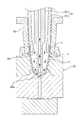
- the enlarged sectional view seen from the front of the preform injection-molded in the said injection molding part is shown.
- the schematic diagram of the said temperature adjustment part is shown.
- the schematic diagram of another example of the said temperature adjustment part is shown.
- FIG. 5 is a cross-sectional view showing how the preform is blow-molded in a blow-molding section.
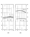
- the graph of the temperature distribution at the time of adjusting the temperature of a preform having a wall thickness of 2.85 mm is shown.
- the graph of the temperature distribution when the temperature of a preform having a wall thickness of 3.85 mm is adjusted is shown.
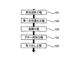
- the flowchart figure of all the processes including the 1st temperature equalization process of a preform is shown.
- Flow chart of the entire process including the first and second soaking process of the preform The schematic diagram of the blow molding apparatus which concerns on 2nd Embodiment of this invention is shown.
- the process drawing of the whole process is shown.
- the temperature change of the preform in the whole process is shown.
- the figure which shows the example of a neck type and a preform is shown.
- FIG. 1 is a perspective view of a blow molding apparatus (having an injection molding section, a temperature adjusting section, a blow molding section, and a take-out section) according to a first embodiment of the present invention
- FIG. FIG. 3 is an enlarged cross-sectional view of the preform viewed from the front
- FIG. 3 is a cross-sectional view showing a state in which the temperature adjustment unit cools the preform with a temperature control core and a temperature control pot
- FIG. FIG. 5 is an enlarged cross-sectional view showing a state in which the preform is cooled by air in the adjusting unit
- FIG. 5 is a cross-sectional view showing the preform being blow-molded in the blow-molding unit.
- the blow molding apparatus 100 includes an injection molding section 10, a temperature adjusting section 20, a blow molding section 30, and a take-out section 40. It is an apparatus for molding and manufacturing the container 1a.
- the injection molding unit 10, the temperature adjusting unit 20, the blow molding unit 30, and the take-out unit 40 are arranged in an array that forms four sides of a square when viewed from above.
- a turntable (not shown) provided with a neck mold 50 (see FIG. 3) for holding the neck portion 3 (see FIG. 2) of the preform 1 molded by the injection molding portion 10 is provided.
- This turntable has four sets of neck molds 50 arranged in an array so as to form four sides of a square when viewed from above. As a result, the turntable rotates counterclockwise on the injection molding unit 10, the temperature adjusting unit 20, the blow molding unit 30, and the take-out unit 40 by 90 degrees about the vertical axis, whereby four sets of neck molds 50 are formed.
- the injection molding unit 10 includes an injection core mold 11, an injection cavity mold 12, and an injection device (not shown), and is provided to injection-mold the preform 1.
- a cooling circuit (not shown) is provided in each of the injection core mold 11 and the injection cavity mold 12, and a cooling medium of about 5 to 20° C. is flown therein.
- the preform 1 is made of a thermoplastic synthetic resin as shown in FIG. 2, and has a bottomed shape (bottomed tubular shape) having a neck part 3 on the open side and a storage part (main body part) 2 on the closed side. Has been formed.
- the reservoir 2 is composed of a body 2a connected to the neck 3 on the open side and a bottom 2b located on the closed side and connected to the body 2a.
- the preform 1 becomes a container 1a (see FIG. 5) by being blow-molded, and has a shape such that the container 1a after blow-molding is contracted vertically and horizontally in the drawing to have a thick wall. doing.
- the injection core mold 11 molds the inner surface shape of the storage part 2 and the neck part 3 of the preform 1
- the injection cavity mold 12 molds the outer surface shape of the storage part 2
- the neck mold 50 molds the inner surface shape of the neck part 3. Shape the outer surface.
- the injection molding unit 10 heats and melts a material of thermoplastic synthetic resin (for example, polyester resin such as PET (polyethylene terephthalate)) at high temperature, and the melted material is injected into an injection core mold 11 by an injection device (not shown).
- Injection (filling) is performed in a molding space (cavity) defined by the injection cavity mold 12 and the neck mold 50, and the material of the injected material near the mold surface (cavity surface) has a melting point (for example, in the case of PET). Is lower than about 255° C.), for example, by cooling to about 20° C. and solidifying to form a surface layer (also appropriately referred to as an outer layer, an outer layer, or a skin layer) in the storage part 2 and molding the preform 1.
- a material of thermoplastic synthetic resin for example, polyester resin such as PET (polyethylene terephthalate)
- the inner layer (also appropriately called the inner layer or the core layer) is set to a temperature not higher than the melting point and not lower than the glass transition temperature (for example, 150 to 200° C.), and blow molding is performed.
- the part 30 is adjusted so as to have a heat quantity that can be stretched.
- the molding cycle time that is, the molding time of the preform 1 is shortened as compared with the conventional case.
- the cooling time is set to be significantly shorter than that of the conventional method.
- the cooling time is set to 2/3 or less of the injection time, preferably 1/2 or less, and more preferably 1/3 or less.
- the injection core mold 11 is formed such that the lateral cross section of the portion corresponding to the storage portion 2 (more specifically, the body portion 2a) of the preform 1 is smaller than the lateral cross section of the portion corresponding to the neck portion 3. ..
- the storage portion 2 is formed to have a smaller internal space area in the direction perpendicular to the axis Z of the preform 1 than the neck portion 3.
- the injection core mold 11 is formed such that its lateral cross section becomes gradually smaller as it approaches the position on the mold surface (cavity surface) corresponding to the bottom portion 2b of the preform 1.
- the inside of the injection-molded preform 1 is formed so that the internal space area that expands in the direction perpendicular to the axis Z of the preform 1 becomes gradually smaller as it approaches the bottom portion 2b of the preform 1. Has been done.
- the preform 1 that has been hardened to some extent after being injection-molded in the injection-molding unit 10 (to the extent that a skin layer is formed on the inner and outer surfaces of the storage unit 2 and the outer shape can be maintained) is an injection core mold while being held by the neck mold 50. 11 and the injection cavity mold 12 are pulled out (released), and as shown in FIG. 1, the turntable is conveyed to the temperature adjusting unit 20 by rotating 90 degrees counterclockwise in a top view. Since this preform 1 is released from the injection molding part 10 at a higher temperature than in the conventional method, the outer layer (skin layer) of the storage part 2 is formed thin while the inner layer (core layer) is formed thick. The retained heat is higher than that of the conventional method.
- the temperature adjusting unit 20 is arranged next to the injection molding unit 10, and as shown in FIGS. 3 and 4, one of the temperature adjusting cavity mold 22 and the temperature adjusting core mold 21 or the air introduction/extraction member 61 is provided. I have it.
- the preform 1 conveyed from the injection molding unit 10 goes down together with the turntable and is inserted into the temperature control cavity mold 22 until the neck mold 50 contacts the centering ring 60 mounted on the temperature control cavity mold 22. ..
- the temperature control core mold 21 or the air introduction/extraction member 61 is inserted into the preform 1 through the upper opening formed in the neck portion 3 of the preform 1.
- the temperature control core mold 21 may be inserted into the preform 1 and then the preform 1 may be inserted into the temperature control cavity mold 22 together with the temperature control core mold 21.
- the temperature control core mold 21 and the temperature control cavity mold 22 are 10° C. or higher and 90° C. or lower, preferably 60° C. or higher and 80° C. or lower due to the flow of the refrigerant (temperature control medium) in the flow passage formed inside. Has been cooled to.
- the air introducing/extracting member 61 allows compressed air for cooling having a predetermined temperature to flow through the reservoir 2.
- the preform 1 conveyed to the temperature adjusting section 20 has a temperature that is too high for blow molding and has a temperature deviation that cannot be completely eliminated during cooling.
- the inner and outer surfaces of the storage section 2 are brought into contact with the temperature control core mold 21 and the temperature control cavity mold 22, or the outer surface is brought into contact with the temperature control cavity mold 22 and air from the air introduction/extraction member 61 is blown onto the inner surface. As a result, the temperature is cooled and adjusted to a temperature suitable for blow molding.
- FIG. 3 shows an example in which the storage part 2 of the preform 1 is cooled by the temperature control cavity mold 22 and the temperature control core mold 21.
- the temperature control core die 21 is formed with a constricted portion 23 a so as not to contact the neck portion 3 when the temperature control core die 21 is inserted into the temperature control cavity die 22.
- the temperature control core die 21 has a taper shape with an angle smaller than that of the injection core die 11 formed in the taper shape of the injection molding part 10.
- the preform 1 can be removed from the injection molding part 10 (mold release) or can be compressed and deformed from a shape that is easy to mold to a desired shape that is easy to blow mold.
- the temperature adjusting core mold 21 contacts and presses substantially the entire inner surface of the storage unit 2 of the preform 1, and the temperature adjusting cavity mold 22 stores the preform 1. It is provided so as to come into contact with and press the substantially entire outer surface of the portion 2. As a result, even if the preform 1 is irregularly contracted and deformed after being released from the injection molding unit 10, the storage unit 2 of the preform 1 is provided between the temperature control core mold 21 and the temperature control cavity mold 22. The shape can be corrected while the preform 1 is cooled by sandwiching.
- the preform 1 is sandwiched between the temperature-controlling core mold 21 and the temperature-controlling cavity mold 22 while being pressed and cooled, so that the preform 1 having the primary shape at the time of injection molding is blow-molded into the final container 1a.
- the temperature may be adjusted simultaneously inside and outside while forcibly compressing and deforming the preform 1 having a secondary shape suitable for the above.
- FIG. 4 shows an example in which the storage part 2 of the preform 1 is cooled by the temperature control cavity mold 22 and the air introduction/extraction member 61.
- the air introducing member 61 is composed of a rod member 62 that is hollow and has an air passage hole inside, and a fitting core (temperature controlling blow core member) 63.
- the rod member 62 is housed inside the fitting core 63 so as to be vertically movable.
- the rod member 62 is provided at its tip with an inward flow port 62a capable of ejecting or sucking air.
- the temperature of the air is appropriately set within the range of, for example, about 0° C. to about 20° C. (normal temperature) according to the wall thickness of the preform 1 and the container 1a.
- the fitting core 63 is configured to fit (closely contact) with the neck portion 3 when the air introducing member 61 is inserted into the preform 1 (when it is in airtight contact). Thereby, the air inside the preform 1 can be prevented from leaking from the neck portion 3 to the outside of the fitting core 63.
- the gap between the rod member 62 and the fitting core 63 is an air circulation path for supplying/discharging air to/from the preform 1.
- a gap formed by the tip of the fitting core 63 and the rod member 62 constitutes a first outer circulation port 64 capable of ejecting or sucking air.
- the inner circulation port 62a and the outer circulation port 64 can be a blower port and a discharge port, respectively.
- the preform 1 is housed in the preform-shaped space of the temperature control cavity mold 22.
- the air introducing member 61 is inserted into the inside of the preform 1 housed in the cavity mold 22 (abuts airtightly).
- air is sent from the outer circulation port 64 of the air introducing member 61 to the inside of the preform 1 while the first inner circulation port 62a is closed, and the storage part 2 of the preform 1 is made to the inner wall of the cavity mold 22. Perform preliminary blow for close contact.
- the inner circulation port 62a is opened, and a cooling blow (cooling blow) for discharging air to the outside of the preform 1 through the outer circulation port 64 while introducing air from the inner circulation port 62a.
- a cooling blow cooling blow
- the preform 1 is cooled from the inside by the convection of the air flowing inside.
- the temperature is adjusted from the outside so as not to fall below the temperature suitable for blow molding, and the temperature deviation caused during injection molding is reduced. Since the cavity mold 22 has a preform-shaped space, the shape of the preform 1 does not change significantly. After cooling for a certain period of time, the cooled preform 1 is moved to the blow molding unit 30.
- the air flow direction of the air introducing member 61 can be appropriately changed.
- air may be sent from the outer circulation port 64 and discharged from the inner circulation port 62a through the inside of the rod member 62.
- air is made to flow from the inner circulation port 62 a to the outer circulation port 64.
- Preform 1 When it is desired to increase the cooling strength on the upper side (upper side of the storage portion 2) of the above, air is made to flow from the outer circulation port 64 to the inner circulation port 62a.
- the air blowing directions of the preliminary blow and the cooling blow may be set to be the same.
- the wall portion 5 of the preform 1 is connected to the neck portion 3 and corresponds to a first wall portion corresponding to a substantially cylindrical body portion, and a bottom portion which is connected to the body portion and has a closed region. And a corresponding second wall portion.
- the preform 1 whose temperature has been adjusted by the temperature adjustment unit 20 is pulled out from the temperature adjustment cavity mold 22 while being held by the neck mold 50, and as shown in FIG. 1, the turntable further rotates 90 degrees counterclockwise. And is conveyed to the blow molding unit 30.
- the blow molding unit 30 is arranged next to the temperature adjusting unit 20 and includes a blow mold 31 and an air blowing unit (not shown).
- the blow mold 31 has a mold surface corresponding to the shape of the container 1a formed inside, and is considerably larger than the temperature control cavity mold 22 of the temperature control unit 20.
- the air blowing section is provided to fill the preform 1 inserted in the blow mold 31 with air.
- the preform 1 conveyed to the blow molding part 30 is inserted into the blow mold 31, the air blowing part is connected to the opening of the neck part 3 of the preform 1, and the air blowing part blows air into the preform 1. Then, as shown in FIG. 5, the storage portion 2 of the preform 1 is inflated until the entire outer surface of the storage portion 2 is pressed against the mold surface of the blow mold 31 to form the container 1a. ing.
- the preform 1 (container 1a) blow-molded by the blow-molding unit 30 is pulled out from the blow mold 31 while being held by the neck mold 50, and as shown in FIG. 1, the turntable is further rotated counterclockwise by 90 degrees. It is rotated and conveyed to the take-out section 40.
- the take-out section 40 is arranged between the blow molding section 30 and the injection molding section 10, as shown in FIG. In the take-out section 40, the neck mold 50 is opened and the container 1a is no longer held, so that the container 1a falls and the container 1a is taken out from the blow molding apparatus 100.
- the blow molding apparatus 100 is configured to release the preform 1 from the injection cavity mold 12 in a high temperature state where the preform 1 is cooled only to an extent that the outer shape of the preform 1 can be maintained. That is, the outer surface temperature of the body 2a of the preform 1 released by the injection molding unit 10 (the temperature of the surface layer on the outer peripheral surface of the body 2a) is the inner surface temperature of the body 2a (the inner surface of the body 2a). Before the temperature becomes higher than the temperature of the surface layer on the surface), for example, the outer surface temperature is higher than the glass transition temperature of the preform by 30° C. or more and 60° C. or less, and the preform 1 is inserted (loaded) into the temperature adjusting unit 20. doing.
- the temperature adjusting unit 20 lowers the outer surface temperature by 10° C. or more and 50° C. or less from the temperature at the time when the preform 1 is inserted (loaded) into the temperature adjusting unit 20, and the inner layer is interposed between the inner and outer surface layers. It is designed to be cooled.
- the glass transition temperature of the PET preform 1 is, for example, about 75°C.
- the preform 1 molded with sufficient cooling time in the injection molding unit 10 tends to come into contact with the injection core mold 11 strongly due to the shrinkage of the resin, while leaving the injection cavity mold 12 away from the injection core mold 11.
- the outside surface temperature is higher than the inside surface temperature.
- the temperature gradient (thermal gradient) between the inner layer and the outer layer of the preform 1 is relatively small.
- the preform 1 is conveyed to the temperature adjusting section 20 while keeping the preform 1 at an extremely high temperature as compared with the conventional technology.
- the preform 1 Since the preform 1 is released from the injection core mold 11 and the injection cavity mold 12 in a state where the heat of the inner layer is higher than that of the conventional one in the injection molding section 10, the temperature gradient between the inner layer and the outer layer is higher than that of the conventional one. growing. Therefore, the heat exchange between the inner layer and the outer layer of the preform 1 is activated. As a result, the outer surface temperature of the preform 1 is once increased by the return heat (the transfer of the amount of heat from the inner layer to the outer layer) during the transportation to the temperature adjusting unit 20, so that the injection molding unit 10 and the temperature adjusting unit 20 are separated from each other.
- the return heat the transfer of the amount of heat from the inner layer to the outer layer
- the short transfer time (the mold opening/closing operation time of the injection molding unit 10 and the transfer time from the injection molding unit 10 to the temperature adjusting unit 20) is used to eliminate the temperature difference between the inner and outer layers, to make the temperature uniform and to remove the temperature deviation. Is promoting. That is, due to the high temperature mold release, the outer layer (skin layer) of the preform 1 is formed during this transfer time (for example, 4.0 seconds to 12.0 seconds, more preferably 4.0 seconds to 8.0 seconds).
- the transfer of heat is accelerated to such an extent that the temperature rapidly rises from a temperature close to that of the injection mold (for example, 5.0°C to 20.0°C) to a temperature of 110°C or higher and 130°C or lower, so that the preform 1 is temperature-uniformized. And enhances the effect of removing unbalanced temperature.
- the preform 1 is allowed to cool and the excess heat amount of the preform 1 generated by the high temperature mold release is released to the outside air, thereby shortening the cooling time of the inner layer required in the temperature adjusting section 20. I am making it.
- the cooling efficiency of the inner layer of the preform 1 and the temperature adjustment efficiency of the inner and outer layers in the temperature adjusting unit 20 can be increased to lower the temperature from the crystallization temperature band in a short time, and the temperature distribution suitable for stretch orientation in a short time. It is possible to adjust the preform in the state, and it is possible to manufacture a container with high transparency and physical properties in a short time. Furthermore, since the outer layer of the preform 1 is heated to a higher temperature and softened by the high temperature release in the injection molding unit 10, it is derived from the injection core mold or the injection cavity mold transferred to the surface layer of the preform 1. Roughness can be reduced or eliminated. As a result, the roughness of the surface layer of the preform 1 immediately before blow molding can be made smaller than in the prior art, and the container 1a having a small surface roughness and excellent surface gloss can be manufactured.
- temperature adjustment is performed so as to make it inversely proportional to the thickness of the wall portion 5 (more specifically, the body portion 2a) of the preform 1 so that at least the outer surface temperature of the preform 1 falls within a predetermined temperature range. It is adjusted to fit inside.
- the inner surface temperature may be adjusted so as to be within a predetermined temperature range. For example, when the thickness of the wall portion 5 is 1.5 mm or more and 3.0 mm or less, the outer surface temperature is about 87° C. or more and 93° C. or less, and when the thickness is 3.0 mm or more and 5.0 mm or less, the outer surface temperature is 77° C.
- the temperature of the preform 1 is adjusted (cooled) by the temperature adjusting unit 20 so that the temperature becomes 83° C. or less, and the temperature of the preform 1 having the thicker wall 5 is lowered when adjusting the temperature of the temperature adjusting unit 20. ..
- thermoplastic resin for example, PET having a glass transition temperature of 50° C. or more and 150° C. or less and a wall thickness of 1.5 mm or more and 4.0 mm or less, more preferably 1.5 mm or more and 3.5 mm or less is a main material.
- PET thermoplastic resin
- the preform 1 is inserted into the temperature control cavity mold 22 of the temperature control unit 20 in a state where the outer surface temperature of the preform 1 is 110° C. or higher and 150° C. or lower, more preferably 100° C. to 135° C. or lower. It is supposed to do.
- thermoplastic resin for example, made of PET having a glass transition temperature of 50° C. or more and 150° C. or less and a wall thickness of 3.0 mm or more and 10.0 mm or less, more preferably 3.5 mm or more and 7.0 mm or less is mainly used as a material.
- the preform 1 to be used is used, the preform 1 is placed in the temperature control cavity mold 22 of the temperature control part 20 in a state where the outer surface temperature of the preform 1 is 100° C. or higher and 140° C. or lower, more preferably 85° C. to 130° C. It is designed to be inserted.
- the molding time of the preform 1 in the injection molding unit 10 that is, the time during which the neck mold 50 is on standby (stationary) in the injection molding unit 10 is set to be short, and the cooling time in the injection molding unit 10 is shortened.
- the temperature adjustment unit 20 secures a shortage of cooling time.
- the cycle time required for each cycle is about 5.0 to about 10.0 seconds, that is, the processing time of each step is about 10.0 seconds or less, and PET preform 1 having a thickness of 3.85 mm is used.
- the cycle time is about 10.0 to about 16.4 seconds, that is, the processing time of each step is about 16.4 seconds or less.
- the temperature adjustment in the temperature adjustment unit 20 of the preform 1 injection-molded by the injection molding unit 10 will be specifically described below.
- FIG. 6 shows that when the wall portion 5 (body portion 2a) has a wall thickness of 1.0 mm to 4.0 mm (more preferably 1.5 mm to 3.5 mm), specifically, a wall thickness of 2.85 mm.
- Fig. 7 shows a graph of temperature distribution when the temperature of the preform of Fig. 7 is adjusted.
- Fig. 7 shows a case where the wall portion 5 (body 2a) has a wall thickness of 3.0 mm to 10.0 mm (more preferably 3.5 mm to 7 mm). (When it is 0.0 mm), specifically, a graph of temperature distribution when the temperature of a preform having a thickness of 3.85 mm is adjusted.
- 6(a) and 7(a) show graphs when the temperature of the preform is adjusted by the conventional technique
- FIGS. 6(b) and 7(b) show the temperature adjustment of the preform according to the present embodiment. The graph at the time of doing is shown.
- the horizontal axis indicates the position in the thickness direction
- the vertical axis indicates temperature
- the temperature distribution curve C1 indicates the temperature distribution before temperature adjustment
- the temperature distribution curve C2 indicates the temperature distribution after temperature adjustment.
- the straight line L1 shows the approximate straight line of the temperature distribution curve C1
- the straight line L2 shows the approximate straight line of the temperature distribution curve C2.
- the horizontal axis indicates the position in the thickness direction
- the vertical axis indicates temperature
- the temperature distribution curve C3 shows the temperature distribution before temperature adjustment
- the temperature distribution curve C4 shows the temperature distribution after temperature adjustment.
- the straight line L3 shows the approximate straight line of the temperature distribution curve C3, and the straight line L4 shows the approximate straight line of the temperature distribution curve C4.
- the horizontal axis indicates the position in the thickness direction
- the vertical axis indicates temperature
- the temperature distribution curve C5 indicates the temperature distribution before temperature adjustment
- the temperature distribution curve C6 indicates the temperature distribution after temperature adjustment.
- the straight line L5 indicates the approximate curve of the temperature distribution curve C5
- the straight line L6 indicates the approximate curve of the temperature distribution curve C6.
- the horizontal axis indicates the position in the thickness direction
- the vertical axis indicates temperature
- the temperature distribution curve C7 indicates the temperature distribution before temperature adjustment
- the temperature distribution curve C8 indicates the temperature distribution after temperature adjustment.
- the straight line L7 indicates the approximate curve of the temperature distribution curve C7
- the straight line L8 indicates the approximate curve of the temperature distribution curve C8.
- the temperatures of the temperature distribution curves C1 to C8 indicate the average temperature of the wall portion 5 (more specifically, the body portion 2a) at the wall thickness position.
- the injection-molded preform 1 needs to be sufficiently cooled in advance by the injection molding unit 10. That is, the time during which the neck mold waits in the injection molding section is about 12.9 seconds or less (machine operation time (transfer time) required for opening/closing the injection molding section 10 and conveying the preform 1). Is about 4.0 seconds, the injection molding time of the preform 1 is about 8.9 seconds (the machine operating time is also assumed to be about 4.0 in the following examples).
- the preform 1 is sufficiently cooled in the injection molding section and then conveyed to the temperature adjusting section.
- the temperature distribution curve C1 when conveyed to the temperature adjusting section is outside.
- the surface temperature is higher than the inner surface temperature.
- the straight line L1 rises to the right from the inside to the outside of the preform 1 so that the outside surface temperature becomes the highest, and the outside surface temperature is about 99° C. (the average temperature of the body portion 2a is about 98° C.). °C).
- the outer surface temperature of the temperature distribution curve C2 after the temperature adjustment is performed by the temperature adjustment unit. It is higher than the inner surface temperature.
- the straight line L2 rises to the right from the inside of the preform 1 to the outside so that the outside surface temperature becomes the highest, and the outside surface temperature is about 95°C (the average temperature of the body portion 2a is about 93°C. ).
- the injection-molded preform 1 is hardly cooled in the injection-molding unit, so the time required for the injection-molding process, that is, the neck mold 50 is injected.
- the waiting time in the molding unit 10 is only about 10.0 seconds or less (the injection molding time of the preform 1 is a total of about 4.0 seconds of injection time and about 2.0 seconds of cooling time). Will be about 6.0 seconds).
- the preform 1 is conveyed to the temperature adjusting section 20 with almost no cooling in the injection molding section 10, and as shown in FIG. 6B, the temperature distribution curve C3 when it is conveyed to the temperature adjusting section 20.
- the straight line L3 descends to the right from the inside to the outside of the preform 1 so that the outside surface temperature becomes the lowest, and the outside surface temperature is about 120° C. (a temperature range of 100° C. to 135° C. ( The average temperature of the body 2a is about 125°C)).
- the outside surface temperature of the temperature distribution curve C4 after being cooled by the temperature adjusting unit 20 is substantially the same as the inside surface temperature.
- the straight line L4 rises to the right from the inner side to the outer side of the preform 1 so that the outer surface temperature becomes the highest, and the outer surface temperature is about 90° C. (85° C. to 105° C.
- the average temperature of part 2a is about 90°C)).
- the temperature generally decreases from the inside to the outside in the wall thickness direction of the wall portion 5 (body portion 2a) of the preform 1 when conveyed to the temperature adjusting portion 20. It is ready to go.
- the preform 1 cooled by the temperature adjusting unit 20 has an inner layer and an inner layer so that the outer surface temperature is lowered by 15° C. or more from the temperature at the time of being inserted (conveyed) in the temperature adjusting unit 20.
- the temperature In the wall thickness direction of the wall portion 5 (body portion 2a) of the preform 1 that has been cooled, the temperature generally rises from the inside to the outside.
- the cooling strength of the inner surface of the preform 1 is set higher than the cooling strength of the outer surface thereof.
- the preform 1 injection-molded is sufficiently processed in the injection molding section as in the case of using the preform 1 having a wall thickness of 2.85 mm. Since it needs to be cooled, the time required for the injection molding process, that is, the time during which the neck mold waits in the injection molding section is about 20.9 seconds or less (the injection molding time of the preform 1 is about 14 seconds). .9 seconds).
- the preform 1 is sufficiently cooled in the injection molding section and then conveyed to the temperature adjusting section.
- the temperature distribution curve C5 when conveyed to the temperature adjusting section is outside.
- the surface temperature is higher than the inner surface temperature.
- the straight line L5 rises to the right from the inside of the preform 1 to the outside so that the outside surface temperature becomes the highest, and the outside surface temperature is about 94°C (the average temperature of the body portion 2a is about 102°C). ).
- the outside surface temperature of the temperature distribution curve C6 after the temperature is adjusted (heat treatment) in the temperature adjusting section is also higher than the inside surface temperature.
- the straight line L6 rises to the right from the inside to the outside of the preform 1 so that the outer surface temperature becomes the highest, and the outer surface temperature is about 103° C. (the average temperature of the body 2a is about 100). °C).
- the injection-molded preform 1 is hardly cooled by the injection-molding unit 10, so that the time required for the injection-molding process, that is, the neck mold 50 is
- the waiting time in the injection molding unit 10 is only about 16.4 seconds or less (the injection molding time of the preform 1 is about 12.9 seconds).
- the preform 1 is conveyed to the temperature adjusting section 20 with almost no cooling in the injection molding section 10, and as shown in FIG. 7B, the temperature distribution curve C7 when the preform 1 is conveyed to the temperature adjusting section 20.
- the straight line L7 descends to the right from the inner side to the outer side of the preform 1 so that the outer surface temperature becomes the lowest, and the outer surface temperature is about 115° C. (a temperature range of 85° C. to 130° C.
- the average temperature of the body 2a is about 126°C.
- the outside surface temperature of the temperature distribution curve C8 after being cooled by the temperature adjusting unit 20 is substantially the same as the inside surface temperature.
- the straight line L8 rises to the right from the inner side to the outer side of the preform 1 so that the outer surface temperature becomes the highest, and the outer surface temperature is about 90° C. (75° C. to 100° C.
- the average temperature of part 2a is about 94°C)).
- the temperature is in a state of generally decreasing from the inside to the outside.
- the preform 1 cooled by the temperature adjusting unit 20 has an inner layer and an inner layer so that the outer surface temperature is lowered by 15° C. or more from the temperature at the time of being inserted (conveyed) in the temperature adjusting unit 20.
- the temperature In the wall thickness direction of the wall portion 5 (body portion 2a) of the preform 1 that has been cooled, the temperature generally rises from the inside to the outside.
- the blow molding apparatus 100 inserts the preform 1 into the temperature adjusting unit 20 before the outer surface temperature of the preform 1 molded by the injection molding unit 10 becomes higher than the inner surface temperature, and the temperature adjusting unit 20 At the same time, the preform 1 is cooled at the same time inside and outside so that at least the outer surface temperature of the preform 1 is lowered in the temperature range of 10° C. to 50° C. compared to the time when it is conveyed to the temperature adjusting unit 20.
- the injection molding process can be carried out in a short time, the molding cycle time can be shortened, and the temperature adjusting section 20 can sufficiently cool the resin. Quality containers can be manufactured.
- the temperature of the preform 1 conveyed to the blow molding unit 30, that is, the temperature of the preform 1 immediately before the blow molding is lower than that of the conventional method. It is set. This allows the preform to be oriented and stretched (substantially uniform biaxial stretching) better than in the conventional method during blow molding, improving the transparency and physical properties of the container to be produced, and further to the fish eye ( It is possible to reduce molding defects (poor appearance) such as tear patterns, ring patterns (uneven stretch) and orange peels (rough surface finish).
- the temperature for transporting the preform 1 from the injection molding unit 10 to the temperature adjusting unit 20 is utilized to equalize the temperature between the inner and outer layers of the preform (hereinafter, referred to as the However, the second temperature equalization may be performed using the time during which the preform 1 is conveyed from the temperature adjusting unit 20 to the blow molding unit 30. These will be described in detail.
- a 4-station type injection molding process 101, a temperature control process 103, a blow molding process 104, and a container removal process 105 are continuously provided.
- a first temperature equalizing step 102 is provided between the step 101 and the temperature adjusting step 103.
- a second temperature equalizing step 106 is further provided between the temperature adjusting step 103 and the blow molding step 104, for the following reason. On the street.
- the local low temperature of the preform 1 is alleviated by allowing the temperature-adjusted preform 1 to stand (standby) for a predetermined time, for example, 2 to 4 seconds immediately before blow molding in the second temperature equalizing step 106.
- a predetermined time for example, 2 to 4 seconds immediately before blow molding
- the temperature of the whole body is made uniform, and the occurrence of the above-mentioned molding failure is prevented.
- the temperature distribution of the preform 1 is naturally fine-tuned by utilizing the heat retained in the preform 1 and the natural cooling resulting from the initial injection molding step 101, so that the temperature deviation occurs. This can be eliminated, and a container having better appearance, thickness distribution, and physical properties can be formed as compared with the case where the second temperature soaking step 106 is not provided.
- the second temperature equalizing step 106 is actually performed. Is performed by using the time obtained by adding the transfer time from the temperature control unit 20 to the blow molding unit 30 and the delay time (standby time) of the mold closing operation of the blow mold 31. That is, while the preform 1 is left (standby) between the pair of blow split molds in the mold open state of the blow mold 31, the preform injection molding and temperature control steps of the subsequent (former molding cycle) are performed in parallel. Then do. As a result, the extension of the cycle time due to the second temperature equalization is minimized and the time efficiency is good. Therefore, it is desirable to set the second temperature equalizing time longer than the first temperature equalizing time. Of course, depending on the case, only the first temperature equalizing step or only the second temperature equalizing step may be adopted.
- FIG. 10 shows a schematic view of the blow molding apparatus according to the second embodiment
- FIG. 11 shows a process drawing of the entire process.
- parts different from the first embodiment will be described, and the same reference numerals are used for the substantially same configurations as those in the first embodiment in the drawings.
- step 1 represents a preform molding step
- step 2 represents a post-preform cooling step (forced cooling step)
- steps 3 and 4 represent a preform temperature equilibration step (natural cooling step)
- 5 indicates a reheating step
- step 6 indicates a soaking step
- step 7 indicates a stretch blow molding step
- step 8 indicates a container unloading step.
- the preform molding step of step 1 corresponds to the injection molding step by the injection molding unit 10 of the first embodiment, and includes the post-preform cooling step of steps 2 to 6, the preform temperature equilibration step, the reheating step, and the uniformizing step.
- the warming step corresponds to the temperature adjusting step by the temperature adjusting section 20 of the first embodiment
- the stretch blow molding step of Step 7 corresponds to the blow molding step of the blow molding section 30 of the first embodiment
- the Step 8 of The container take-out step corresponds to the take-out step by the take-out unit 40 of the first embodiment.
- the rotary disk is provided on the injection molding unit 10, the temperature adjusting unit 20, the blow molding unit 30, and the unloading unit 40 in 90 degrees counterclockwise about the vertical axis. It is provided to rotate (see FIG. 1).
- each of the four sets of the neck molds 50 sequentially moves the injection molding unit 10, the temperature adjusting unit 20, the blow molding unit 30, and the take-out unit 40 at the same time, and the neck molds 50. Each step is performed for the same time on the preform 1 held at.
- the preform 1 is sequentially transported on the rail (transport path) 6 and the injection molding station 110, the post-cooling station 115, Each process including a temperature adjustment station (reheating station) 120, a blow molding station 130, and an ejection station is performed.
- the blow molding apparatus 200 is configured to sequentially cool and adjust the temperature of the conveyed preform 1.
- the post-cooling station 115 is included in a part of the temperature adjusting station 120 in a broad sense, and is a station that particularly takes charge of forced cooling of the preform 1.
- one molding cycle time of the blow molding device 200 can be regarded as substantially the same as the injection molding time of the preform 1 (time of the injection molding process).
- the number of blow moldings per molding cycle time is defined by M/N.
- the M/N is preferably an integer of 2, 3, or 4, but is not limited to this. That is, the injection-molded preform for one batch may be blow molded by dividing into a plurality of times.
- the injection-molded preform 1 generates heat at a temperature higher than the glass transition point of the thermoplastic synthetic resin material (for example, PET resin).
- the thermoplastic synthetic resin material for example, PET resin.
- Injection molding in a soft state while the material of the outer layer (skin layer) is solidified to such an extent that the outer shape of the preform 1 can be maintained after mold release and the material of the inner layer (core layer) is at a high temperature near the melting point) It is released from the station 110.
- the blow molding apparatus 200 takes out the preform 1 from the injection molding cavity mold 12 of the injection molding station 110 before the outer surface temperature of the preform 1 molded in the injection molding station 110 becomes higher than the inner surface temperature, and the step 2 Of the preform 1 is cooled immediately after the preform cooling step, and then the natural cooling step (preform temperature equilibrium step) of steps 3 and 4 is performed to measure the average temperature of the body portion 2b of the preform 1 immediately after the injection molding step. Is cooled by 10° C. or more and 50° C. or less. As a result, the preform 1 that has accumulated heat during injection molding is molded into the final container 1a at the blow molding station 130 while utilizing the heat retained by the inner layer.
- the blow molding apparatus 200 shortens the injection molding process and shortens the preform molding cycle (injection molding cycle) by the post-cooling function using the temperature control pot mold of the temperature control process. There is.
- the cooling time is set to 2/3 or less, 1/2 or less, 1/3 or less of the injection time (filling time), preferably about 0 (zero) seconds. Is provided.
- the blow molding device 200 sets the injection molding die set to 5° C. to 20° C. over a predetermined injection time (the injection molding die 11 of the first embodiment). , 12 and 50), the material is injected (filled) into the molding space, and after a short predetermined cooling time close to 0 (zero) seconds, the injection molding of the preform 1 is completed. Then, the blow molding apparatus 200 takes out the preform 1 from the injection molding station 110 or into a receiving pot mold (not shown) over a predetermined machine operation time (release), Step 1 in FIG. 10, and FIG. Injection molding process). For example, the injection time (filling time) is set to 3.0 seconds to 3.5 seconds, and the cooling time is set to 0.5 seconds to 1.0 seconds.
- the machine operating time in the injection molding station 110 is the mold opening/closing time of the injection molding die and the time for transferring the preform 1 from the injection molding die to the receiving pot mold.
- the machine operation time is set to, for example, 3.5 seconds to 4.0 seconds.
- the injection molding time (the total of the injection time, the cooling time, and the machine operation time) of the present embodiment is set to a time shorter than the injection molding time (conventional injection molding cycle) of the conventional technique (WO2012-057016A). Has been done. ..
- the blow molding apparatus 200 retracts and moves the preform 1 from the injection molding station 110 while the preform 1 is kept in the receiving pot mold, and the preform 1 is transferred by the conveying member (not shown). Transfer to the temperature adjustment station 120.
- the temperature of the preform 1 is soaked by utilizing this mechanical operation time.
- the outer layer (skin layer) of the preform 1 is heated by 80° C. or more as compared with the temperature of the injection molding station 110 immediately after the mold release due to heat transfer from the inner layer (core layer).
- the blow molding apparatus 200 operates the temperature control station 120, or more accurately, the preform 1 carried into the temperature control cavity mold 22 (cooling pot mold) of the post-cooling station 115. Then, a forced cooling step (post-cooling step) is performed (step 2 in FIG. 10, second temperature control step in FIG. 11 (forced cooling step)).
- the preform 1 comes into contact with the temperature control cavity mold 22 set at a glass transition temperature of the material or lower (for example, 60° C. or lower) on the outer surface side and is forcibly cooled.
- the blow molding device 200 causes the preform 1 to be carried by the rail 6 by a mechanical operation such as reversing and lowering the temperature control cavity mold 22, and the conveyance member (not shown). (Step 3 in FIG. 10).
- the preform 1 is transferred to the temperature adjusting station 120 along the rail 6 along with the conveying member by a mechanical operation using an electric motor, a sprocket or the like (step 4 in FIG. 10).
- the blow molding apparatus 200 operates at the temperature adjusting station 120 from immediately after the end of the post-cooling step to immediately before the start of the reheating step. Is naturally cooled and soaked (third temperature adjusting step (natural cooling step) in FIG. 11).
- the blow molding apparatus 200 reheats, soaks, and soaks the preform 1 in the reheating step of the temperature adjusting station 120. Then, heating and soaking are carried out in this order (step 5 in FIG. 10, fourth temperature adjusting step (reheating step) in FIG. 11).
- the blow molding apparatus 200 When the preform 1 is heated and soaked in the order of reheating, soaking, and reheating, the blow molding apparatus 200 is conveyed along the rail 6 in the atmosphere to soak the preform 1. After warming, the preform 1 is carried into the blow molding station 130 (step 6 in FIG. 10, fifth temperature adjusting step in FIG. 11 (temperature equalizing step)). Immediately before blow molding, heat transfer occurs in the inner/outer layer of the preform 1 (skin layer-core layer) or in the thickness direction of the body 2b to reduce the temperature difference between the inner and outer layers, and stabilize the temperature distribution of the preform 1 in equilibrium. Therefore, the temperature conditions of the preform 1 immediately before blow molding can be optimized. The time of this step is set to, for example, about 1.0 second to 2.0 seconds.
- the blow molding apparatus 200 blow-molds the preform 1 to mold the container 1a in a blowing step (step 7 in FIG. 10, blow in FIG. 11). Molding process).
- the blow-molding apparatus 200 carries out by mechanical operation and takes out the container 1a (step 8 in FIG. 10, take-out step in FIG. 11).
- M for example, 36
- preforms 1 that are injected at one time in the injection step N (12 pieces) smaller than M pieces each are subjected to a temperature control step, a natural cooling step, The reheating process and the blowing process are performed.
- the temperature control step, the natural cooling step, and the reheating step are carried out continuously while the preform 1 is conveyed along the rails 6, but in the blow step, 12 pieces are blow-molded in three batches. Is supposed to do.
- the time required for the entire process of shortening the cycle by the blow molding device 200 is shorter than the time required for the entire process by the conventional device.
- FIG. 12 shows changes in the average temperature in the body portion 2b of the preform 1 in the entire process.
- the horizontal axis represents time and the vertical axis represents the temperature of the preform 1.
- the injection molding step corresponds to step 1 in FIG. 10 (injection molding step in FIG. 11)
- the temperature equilibrium step 1 corresponds to step 1 in FIG. 10 (first temperature adjustment step in FIG. 11)
- the cooling step corresponds to step 2 in FIG. 10 (second temperature adjustment step in FIG. 11)
- the temperature equilibrium step 2 corresponds to step 4 in FIG. 10 (third temperature adjustment step in FIG. 11)
- the process, the soaking process, and the heating 2 process correspond to the process 5 of FIG. 10 (the fourth temperature adjusting process of FIG. 11), and the temperature equilibrium stabilizing process is the process 6 of FIG. 10 (the fifth temperature of FIG. 11). Adjustment process).
- each step is performed under the same conditions up to the temperature equilibrium step, but after the heating 1 step, each step is divided into 3 times.
- the process is going on. That is, of the 36 preforms 1 injection-molded at one time in the injection molding process, 12 change in temperature as indicated by route R1 and another 12 change in temperature as indicated by route R2. , And another 12 are changing in temperature as shown by route R3.
- the routes R1, R2, and R3 are divided after the temperature has settled to a state where there is almost no temperature difference between the preforms.
- the preform 1 In the post-cooling process of the temperature adjustment station 120, the preform 1 is rapidly cooled to a temperature not higher than the optimum blowing temperature, so that the difference in temperature deviation (heat history) resulting from the injection molding process between the preforms 1 is efficiently (proactively). Can be reduced. Further, by the time from the injection molding station 110 to the reheating step of the temperature adjustment station 120, the preform 1 is de-uniformed and the temperature is soaked, and the preform 1 is sufficiently cooled to a temperature near or below the glass transition point. Has been done.
- the temperature decrease rate (temperature gradient) of the preform 1 with respect to the time axis becomes gentle, so that the temperature history of the preform 1 of each route R1, R2, R3 that is loaded and unloaded at different times in the reheating step is omitted. Can be set the same. In other words, since the preforms 1 that have gone through any route R1, R2, R3 can be adjusted to substantially the same temperature, the final product 1a has substantially the same quality.
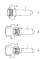
- FIG. 13 shows an example of a neck type and a preform.
- the neck mold of the blow molding device 200 has a lip mold design, so that the mold clamping device of a small size can achieve the maximum number of products and the maximum neck size.
- FIG. 13A shows a first lip mold (standard lip mold) in which the support ring of the preform 1 is set on a dividing surface (PL: parting line) with the injection cavity mold.
- FIG. 13( b) shows a second lip mold (single lip mold) that enables the formation of the preform 1 suitable for a large-sized (capacity) container by forming a reverse taper design above the body below the support ring.
- FIG. 13A shows a first lip mold (standard lip mold) in which the support ring of the preform 1 is set on a dividing surface (PL: parting line) with the injection cavity mold.
- FIG. 13( b) shows a second lip mold (single lip mold) that enables the formation of the preform 1 suitable
- 13(c) shows a die for reducing the size of the lip die and arranging two reduced diameter portions (a taper portion and an inverse taper portion) at the upper and lower ends, respectively, at the time of injection molding of the preform 1.
- the 3rd lip mold double lip mold which can reduce mold clamping power is shown.
- the blow molding apparatus 200 changes the concept of shortening the cycle time when using a conventional thin preform.
- the blow molding apparatus 200 has an effect of improving the orientation degree by adopting a preform design with a high draw ratio (the body is thicker and shorter than the conventional one). That is, it is possible to manufacture a container having high physical properties (rigidity) by improving the degree of orientation of the synthetic resin material by utilizing the low-temperature stretching blow characteristic that the shaping temperature is lowered at the time of high-magnification stretching.
- the second lip mold of the reverse taper type design in which the upper part of the body of the preform 1 is cooled to a temperature not higher than the optimum blowing temperature, and the mold clamping force It corresponds to the third lip mold (double taper lip etc.) of the design to reduce.
- the blow molding apparatus 200 can perform the blow molding process a plurality of times (for example, three times) during one injection molding process, as the production amount of the bottle container 1a is increased, the blow molding process per bottle container 1a is increased. Power consumption associated with manufacturing can be reduced.
- the molding cycle time can be shortened from the conventional 11 seconds to approximately 7 seconds. ..
- the production amount of the bottle containers 1a per unit time can be increased from about 13,000 to about 18,000.
- the power consumption of the blow molding device 200 per unit time is substantially the same, but the production amount can be increased by about 38%, so the power consumption associated with the production of each bottle container 1a is about the same as before. It can be reduced by 38%.
- the blow molding device 200 includes a multi-stage temperature adjusting process (post-cooling process, plural temperature equalizing processes, reheating process and temperature balance stabilizing process) and a machine between the injection molding process and the blow molding process. Since it has multiple temperature equalization processes that use operating time, you can select the shape of preform 1 that does not depend on the neck type (lip type) design, and secure sufficient heating time that can adjust the temperature distribution. can do.
- the synthetic resin material forming the preform 1 is not limited to PET.
- PET polyethylene naphthalate
- PC polycarbonate
- Tritan tritan
- PP polypropylene
- PE polyethylene
- PCLA polycyclohexylene dimethylene terephthalate
Landscapes
- Engineering & Computer Science (AREA)
- Mechanical Engineering (AREA)
- Manufacturing & Machinery (AREA)
- Physics & Mathematics (AREA)
- Thermal Sciences (AREA)
- Blow-Moulding Or Thermoforming Of Plastics Or The Like (AREA)
Abstract
Priority Applications (6)
| Application Number | Priority Date | Filing Date | Title |
|---|---|---|---|
| EP20749786.8A EP3919256A4 (fr) | 2019-01-31 | 2020-01-31 | Dispositif et procédé de production d'un récipient en résine |
| JP2020542474A JP6770666B1 (ja) | 2019-01-31 | 2020-01-31 | 樹脂製容器の製造装置および製造方法 |
| US17/427,401 US11850788B2 (en) | 2019-01-31 | 2020-01-31 | Device and method for producing resin container |
| CN202080023615.XA CN113613861A (zh) | 2019-01-31 | 2020-01-31 | 用于生产树脂容器的装置和方法 |
| KR1020217024558A KR102646476B1 (ko) | 2019-01-31 | 2020-01-31 | 수지제 용기의 제조장치 및 제조방법 |
| US18/496,332 US20240059004A1 (en) | 2019-01-31 | 2023-10-27 | Device and method for producing resin container |
Applications Claiming Priority (6)
| Application Number | Priority Date | Filing Date | Title |
|---|---|---|---|
| JP2019-015971 | 2019-01-31 | ||
| JP2019015971 | 2019-01-31 | ||
| JP2019027545 | 2019-02-19 | ||
| JP2019-027545 | 2019-02-19 | ||
| JP2019-178433 | 2019-09-30 | ||
| JP2019178433 | 2019-09-30 |
Related Child Applications (2)
| Application Number | Title | Priority Date | Filing Date |
|---|---|---|---|
| US17/427,401 A-371-Of-International US11850788B2 (en) | 2019-01-31 | 2020-01-31 | Device and method for producing resin container |
| US18/496,332 Continuation US20240059004A1 (en) | 2019-01-31 | 2023-10-27 | Device and method for producing resin container |
Publications (1)
| Publication Number | Publication Date |
|---|---|
| WO2020158920A1 true WO2020158920A1 (fr) | 2020-08-06 |
Family
ID=71842148
Family Applications (1)
| Application Number | Title | Priority Date | Filing Date |
|---|---|---|---|
| PCT/JP2020/003653 WO2020158920A1 (fr) | 2019-01-31 | 2020-01-31 | Dispositif et procédé de production d'un récipient en résine |
Country Status (6)
| Country | Link |
|---|---|
| US (2) | US11850788B2 (fr) |
| EP (1) | EP3919256A4 (fr) |
| JP (2) | JP6770666B1 (fr) |
| KR (1) | KR102646476B1 (fr) |
| CN (1) | CN113613861A (fr) |
| WO (1) | WO2020158920A1 (fr) |
Cited By (1)
| Publication number | Priority date | Publication date | Assignee | Title |
|---|---|---|---|---|
| JP2021054068A (ja) * | 2019-01-31 | 2021-04-08 | 日精エー・エス・ビー機械株式会社 | 樹脂製容器の製造装置および製造方法 |
Families Citing this family (2)
| Publication number | Priority date | Publication date | Assignee | Title |
|---|---|---|---|---|
| CN117940266A (zh) * | 2021-07-07 | 2024-04-26 | 日精Asb机械株式会社 | 树脂制容器的制造方法及温度调整装置 |
| WO2023182494A1 (fr) * | 2022-03-25 | 2023-09-28 | 日精エー・エス・ビー機械株式会社 | Dispositif et procédé de production d'un récipient en résine |
Citations (10)
| Publication number | Priority date | Publication date | Assignee | Title |
|---|---|---|---|---|
| JPS5291067A (en) * | 1976-01-22 | 1977-08-01 | American Can Co | Method of blow molding container |
| JPH0462028A (ja) * | 1990-06-25 | 1992-02-27 | Dainippon Printing Co Ltd | 高延伸ブロー成形容器の製造方法 |
| JPH0462027A (ja) * | 1990-06-25 | 1992-02-27 | Dainippon Printing Co Ltd | 高延伸ブロー成形容器の製造方法 |
| JPH0465216A (ja) | 1990-07-06 | 1992-03-02 | Dainippon Printing Co Ltd | 予備成形体の温度調節装置 |
| JPH05185493A (ja) | 1991-07-10 | 1993-07-27 | Nissei Asb Mach Co Ltd | 高速型二軸延伸吹込成形方法 |
| JPH06315973A (ja) | 1993-04-30 | 1994-11-15 | Nissei Asb Mach Co Ltd | 成形装置 |
| EP0900135B1 (fr) | 1996-04-18 | 2000-11-29 | SIPA S.p.A. | Ameliorations apportees a un procede et a une installation de fabrication d'ebauches de resine thermoplastique |
| WO2012057016A1 (fr) | 2010-10-25 | 2012-05-03 | 日精エー・エス・ビー機械株式会社 | Dispositif de moulage par étirage-soufflage par injection et dispositif de chauffage de pièce moulée |
| WO2013012067A1 (fr) | 2011-07-20 | 2013-01-24 | 日精エー・エス・ビー機械株式会社 | Appareil de régulation de température pour préformes, procédé de régulation de température pour préformes, récipient en résine et procédé de production d'un récipient en résine |
| WO2017098673A1 (fr) | 2015-12-11 | 2017-06-15 | 株式会社青木固研究所 | Moule de moulage par injection pour machine de moulage par injection-soufflage avec bi-étirage, procédé de moulage d'un préforme, préforme, et procédé de moulage d'un récipient, et récipient |
Family Cites Families (16)
| Publication number | Priority date | Publication date | Assignee | Title |
|---|---|---|---|---|
| JP3017602B2 (ja) * | 1992-05-27 | 2000-03-13 | 日精エー・エス・ビー機械株式会社 | 再充填可能な合成樹脂製容器 |
| JP2954858B2 (ja) * | 1994-09-16 | 1999-09-27 | 日精エー・エス・ビー機械株式会社 | 射出延伸ブロー成形装置及び方法 |
| WO2000023252A1 (fr) * | 1998-10-20 | 2000-04-27 | A.K. Technical Laboratory, Inc. | Procede de soufflage bi-oriente |
| JP4927594B2 (ja) * | 2007-02-22 | 2012-05-09 | 東洋製罐株式会社 | プリフォームの整列搬送装置およびその整列搬送方法 |
| JP5033469B2 (ja) * | 2007-05-08 | 2012-09-26 | 株式会社青木固研究所 | 耐熱ボトルの射出延伸ブロー成形方法 |
| JP4582464B2 (ja) | 2007-06-25 | 2010-11-17 | 東洋製罐株式会社 | 圧縮成形によるプリフォームの成形方法 |
| US9023446B2 (en) | 2009-09-22 | 2015-05-05 | Graham Packaging Lc, L.P. | PET containers with enhanced thermal properties and process for making same |
| US8507063B2 (en) | 2009-09-22 | 2013-08-13 | Graham Packaging Lc, L.P. | Pet containers with enhanced thermal properties |
| EP2549988A1 (fr) | 2010-03-23 | 2013-01-30 | Apr Applied Pharma Research S.A. | Systèmes d'administration de médicaments à dissolution rapide |
| JP6085815B2 (ja) * | 2011-10-24 | 2017-03-01 | 日精エー・エス・ビー機械株式会社 | 射出ブロー成形装置及びそれに用いられる金型ユニット |
| JP6570845B2 (ja) * | 2015-02-27 | 2019-09-04 | 株式会社吉野工業所 | 容器製造装置 |
| WO2017073685A1 (fr) * | 2015-10-29 | 2017-05-04 | 日精エー・エス・ビー機械株式会社 | Ensemble moule métallique, appareil de moulage par soufflage et procédé de moulage par soufflage |
| KR102507303B1 (ko) | 2016-02-22 | 2023-03-08 | 삼성전자주식회사 | 메모리 소자 |
| KR101804424B1 (ko) * | 2017-04-20 | 2017-12-04 | 안광석 | 저장 용기의 제조장치 |
| CN113613861A (zh) | 2019-01-31 | 2021-11-05 | 日精Asb机械株式会社 | 用于生产树脂容器的装置和方法 |
| JP6778354B1 (ja) * | 2019-01-31 | 2020-10-28 | 日精エー・エス・ビー機械株式会社 | 樹脂製容器の製造装置及び製造方法 |
-
2020
- 2020-01-31 CN CN202080023615.XA patent/CN113613861A/zh active Pending
- 2020-01-31 JP JP2020542474A patent/JP6770666B1/ja active Active
- 2020-01-31 EP EP20749786.8A patent/EP3919256A4/fr active Pending
- 2020-01-31 US US17/427,401 patent/US11850788B2/en active Active
- 2020-01-31 WO PCT/JP2020/003653 patent/WO2020158920A1/fr unknown
- 2020-01-31 KR KR1020217024558A patent/KR102646476B1/ko active IP Right Grant
- 2020-09-24 JP JP2020159284A patent/JP7482731B2/ja active Active
-
2023
- 2023-10-27 US US18/496,332 patent/US20240059004A1/en active Pending
Patent Citations (11)
| Publication number | Priority date | Publication date | Assignee | Title |
|---|---|---|---|---|
| JPS5291067A (en) * | 1976-01-22 | 1977-08-01 | American Can Co | Method of blow molding container |
| JPH0462028A (ja) * | 1990-06-25 | 1992-02-27 | Dainippon Printing Co Ltd | 高延伸ブロー成形容器の製造方法 |
| JPH0462027A (ja) * | 1990-06-25 | 1992-02-27 | Dainippon Printing Co Ltd | 高延伸ブロー成形容器の製造方法 |
| JPH0465216A (ja) | 1990-07-06 | 1992-03-02 | Dainippon Printing Co Ltd | 予備成形体の温度調節装置 |
| JPH05185493A (ja) | 1991-07-10 | 1993-07-27 | Nissei Asb Mach Co Ltd | 高速型二軸延伸吹込成形方法 |
| JPH06315973A (ja) | 1993-04-30 | 1994-11-15 | Nissei Asb Mach Co Ltd | 成形装置 |
| EP0900135B1 (fr) | 1996-04-18 | 2000-11-29 | SIPA S.p.A. | Ameliorations apportees a un procede et a une installation de fabrication d'ebauches de resine thermoplastique |
| WO2012057016A1 (fr) | 2010-10-25 | 2012-05-03 | 日精エー・エス・ビー機械株式会社 | Dispositif de moulage par étirage-soufflage par injection et dispositif de chauffage de pièce moulée |
| WO2013012067A1 (fr) | 2011-07-20 | 2013-01-24 | 日精エー・エス・ビー機械株式会社 | Appareil de régulation de température pour préformes, procédé de régulation de température pour préformes, récipient en résine et procédé de production d'un récipient en résine |
| JP2016199053A (ja) * | 2011-07-20 | 2016-12-01 | 日精エー・エス・ビー機械株式会社 | 樹脂製容器のブロー成形方法 |
| WO2017098673A1 (fr) | 2015-12-11 | 2017-06-15 | 株式会社青木固研究所 | Moule de moulage par injection pour machine de moulage par injection-soufflage avec bi-étirage, procédé de moulage d'un préforme, préforme, et procédé de moulage d'un récipient, et récipient |
Non-Patent Citations (2)
| Title |
|---|
| ANONYMOUS: "DSM Amite® D04 300 PET (European Grade)", SONGHAN PLASTIC TECHNOLOGY CO.,LTD., 1 January 2016 (2016-01-01), pages 1 - 3, XP093151208, [retrieved on 20240412] |
| See also references of EP3919256A4 |
Cited By (3)
| Publication number | Priority date | Publication date | Assignee | Title |
|---|---|---|---|---|
| JP2021054068A (ja) * | 2019-01-31 | 2021-04-08 | 日精エー・エス・ビー機械株式会社 | 樹脂製容器の製造装置および製造方法 |
| US11850788B2 (en) | 2019-01-31 | 2023-12-26 | Nissei Asb Machine Co., Ltd. | Device and method for producing resin container |
| JP7482731B2 (ja) | 2019-01-31 | 2024-05-14 | 日精エー・エス・ビー機械株式会社 | 樹脂製容器の製造装置および製造方法 |
Also Published As
| Publication number | Publication date |
|---|---|
| EP3919256A1 (fr) | 2021-12-08 |
| JPWO2020158920A1 (ja) | 2021-02-18 |
| KR20210109611A (ko) | 2021-09-06 |
| JP6770666B1 (ja) | 2020-10-14 |
| US20240059004A1 (en) | 2024-02-22 |
| KR102646476B1 (ko) | 2024-03-11 |
| US11850788B2 (en) | 2023-12-26 |
| JP2021054068A (ja) | 2021-04-08 |
| JP7482731B2 (ja) | 2024-05-14 |
| CN113613861A (zh) | 2021-11-05 |
| EP3919256A4 (fr) | 2022-10-12 |
| US20220097286A1 (en) | 2022-03-31 |
Similar Documents
| Publication | Publication Date | Title |
|---|---|---|
| JP7291062B2 (ja) | 樹脂製の容器の製造方法 | |
| WO2020158920A1 (fr) | Dispositif et procédé de production d'un récipient en résine | |
| WO2020158917A1 (fr) | Dispositif de production et procédé de production pour contenants en résine | |
| JP7492894B2 (ja) | 樹脂製容器の製造装置、温度調整装置、樹脂製容器の製造方法、及び温度調整方法 | |
| CN113547721B (zh) | 注射拉伸吹塑成型机以及聚乙烯制容器的成型方法 | |
| US20240181693A1 (en) | Resin container manufacturing apparatus, temperature adjusting device, resin container manufacturing method, and temperature adjusting method | |
| WO2022220270A1 (fr) | Procédé de production et dispositif de production pour récipient en résine | |
| CN114555330A (zh) | 树脂容器的制造方法及树脂容器的制造设备 |
Legal Events
| Date | Code | Title | Description |
|---|---|---|---|
| ENP | Entry into the national phase |
Ref document number: 2020542474 Country of ref document: JP Kind code of ref document: A |
|
| 121 | Ep: the epo has been informed by wipo that ep was designated in this application |
Ref document number: 20749786 Country of ref document: EP Kind code of ref document: A1 |
|
| ENP | Entry into the national phase |
Ref document number: 20217024558 Country of ref document: KR Kind code of ref document: A |
|
| NENP | Non-entry into the national phase |
Ref country code: DE |
|
| ENP | Entry into the national phase |
Ref document number: 2020749786 Country of ref document: EP Effective date: 20210831 |