WO2020158880A1 - 電気掃除機 - Google Patents
電気掃除機 Download PDFInfo
- Publication number
- WO2020158880A1 WO2020158880A1 PCT/JP2020/003494 JP2020003494W WO2020158880A1 WO 2020158880 A1 WO2020158880 A1 WO 2020158880A1 JP 2020003494 W JP2020003494 W JP 2020003494W WO 2020158880 A1 WO2020158880 A1 WO 2020158880A1
- Authority
- WO
- WIPO (PCT)
- Prior art keywords
- dust
- unit
- air flow
- vacuum cleaner
- flow path
- Prior art date
- Legal status (The legal status is an assumption and is not a legal conclusion. Google has not performed a legal analysis and makes no representation as to the accuracy of the status listed.)
- Ceased
Links
Images


Classifications
-
- A—HUMAN NECESSITIES
- A47—FURNITURE; DOMESTIC ARTICLES OR APPLIANCES; COFFEE MILLS; SPICE MILLS; SUCTION CLEANERS IN GENERAL
- A47L—DOMESTIC WASHING OR CLEANING; SUCTION CLEANERS IN GENERAL
- A47L9/00—Details or accessories of suction cleaners, e.g. mechanical means for controlling the suction or for effecting pulsating action; Storing devices specially adapted to suction cleaners or parts thereof; Carrying-vehicles specially adapted for suction cleaners
- A47L9/28—Installation of the electric equipment, e.g. adaptation or attachment to the suction cleaner; Controlling suction cleaners by electric means
Definitions
- the present invention relates to an electric vacuum cleaner.
- a mechanism for detecting that the amount of dust collected in the dust collecting section has reached the full amount (for example, Patent Documents 1 to 3). By detecting the full amount of dust using these mechanisms and notifying it to the user, the user can remove dust collected in the dust collecting section at an appropriate timing, and suppress a decrease in suction force. it can.
- the present invention has been made in view of the above circumstances, and provides an electric vacuum cleaner having a dust full amount detection mechanism with few malfunctions.
- the present invention provides a suction port, an electric blower provided to suck air into the electric vacuum cleaner from the suction port, and a collection unit provided to collect and collect dust in the air sucked from the suction port.
- a dust part an air flow path provided so that the air sucked from the suction port flows to the dust collecting part, a dust detection sensor provided in the air flow path, a notification part, and a control part.
- the dust detection sensor is provided so as to detect dust passing through the air flow passage, and the control unit integrates the amount of dust passing through the air flow passage based on the sensor output of the dust detection sensor.
- an electric cleaning device which is provided so as to notify the user via the notification unit when it is determined that the integrated amount of dust passing through the air flow path exceeds a predetermined amount. Machine.
- the dust full amount determination is performed based on the accumulated dust amount calculated from the sensor output of the dust detection sensor, it is possible to reduce malfunctions of the dust full amount detection.
- FIG. 3 is a schematic cross-sectional view of the electric vacuum cleaner taken along the broken line AA shown in FIGS. It is a block diagram which shows the electric constitution of the vacuum cleaner of one Embodiment of this invention. It is a block diagram which shows the electric constitution of the vacuum cleaner of one Embodiment of this invention. It is a schematic sectional drawing of the dust collection part contained in the vacuum cleaner of one embodiment of the present invention.
- the vacuum cleaner of the present invention is provided with a suction port, an electric blower provided to suck air into the vacuum cleaner from the suction port, and to collect and collect dust in the air sucked from the suction port.
- a dust collecting section provided, an air flow path provided so that the air sucked from the suction port flows to the dust collecting section, a dust detection sensor provided in the air flow path, and a notification section,
- the dust detection sensor is provided so as to detect dust passing through the air flow passage
- the control unit includes dust that has passed through the air flow passage based on a sensor output of the dust detection sensor.
- the dust collector included in the electric vacuum cleaner of the present invention preferably has a dust box provided to collect dust and a removal sensor provided to detect removal of the dust box, and the control unit is removable. It is preferable that the sensor is provided so as to reset the integrated amount of the dust that has passed through the air flow path when detecting the removal of the dust box. As a result, the control unit can reset the accumulated amount of dust at an appropriate timing, and can notify that dust must be discarded at an appropriate timing.
- the electric blower preferably has a fan and a first motor that rotates the fan, and the control unit includes a first measurement unit that is provided to measure an input power, an input current, or a rotation speed of the first motor.
- the air flow It is preferable to have, and when it is determined that the input power, the input current, or the rotation speed of the first motor measured by the first measuring unit has changed more than a predetermined change amount compared to the previous operation, the air flow It is preferably provided so as to reset the integrated amount of dust that has passed through the road.
- the control unit can reset the accumulated amount of dust at an appropriate timing, and can notify that dust must be discarded at an appropriate timing.
- the integrated amount of dust that has passed through the air flow path has not reached a predetermined amount, but the input power, input current or rotation speed of the first motor measured by the first measurement unit is not within the normal range. If it is determined that the filter needs to be cleaned, the user is preferably notified via the notification unit. This allows the user to clean the filter at an appropriate time.
- the dust collecting unit may include a dust box provided to collect dust separated by centrifugation, an inner cylinder having a side filter and a screw, and a second motor provided to rotate the screw. preferable. Further, the screw is preferably provided so as to compress the dust collected in the dust box.
- control unit has a second measurement unit provided so as to measure the input current of the second motor, and the cumulative amount of dust that has passed through the air flow path has not reached a predetermined amount. Is provided to notify the user via the notification unit that the side filter needs to be cleaned when it is determined that the input current value of the second motor measured by the second measurement unit is higher than the predetermined value. It is preferable. This allows the user to clean the side filter at an appropriate time.
- control unit determines that the accumulated amount of dust that has passed through the air flow path has not reached the predetermined amount, but the drive time of the electric blower has exceeded the predetermined time, it notifies that the dust detection sensor needs maintenance. It is preferably provided so as to notify the user via the section. As a result, the user can know the malfunction of the dust detection sensor at an early stage and can perform maintenance.
- FIG. 1 is a schematic perspective view of the electric vacuum cleaner of the present embodiment
- FIG. 2 is a schematic rear view of the electric vacuum cleaner
- FIG. 3 is a broken line AA shown in FIGS.
- FIG. 4 is a block diagram which shows the electric constitution of an electric vacuum cleaner.
- the electric vacuum cleaner 70 according to the present embodiment includes a suction port 2, an electric blower 16 provided to suck air from the suction port 2 into the electric vacuum cleaner 70, and dust 10 in the air sucked from the suction port 2.
- a dust collecting portion 4 provided to collect and store the air, an air passage 3 provided so that air sucked from the suction port 2 flows to the dust collecting portion 4, and an air passage 3 provided to the air passage 3.
- a dust detection sensor 7, a notification unit 9, and a control unit 8 are provided, and the dust detection sensor 7 is provided so as to detect the dust 10 passing through the air flow path 3, and the control unit 8 controls the dust detection sensor 7 Is provided so as to integrate the amount of dust 10 that has passed through the air flow path 3 based on the sensor output of, and if it is determined that the integrated amount of dust 10 that has passed through the air flow path 3 has exceeded a predetermined amount, the dust collection unit It is characterized in that it is provided so as to notify the user via the notification unit 9 that it is necessary to dispose of the dust 10 accumulated in 5.
- the electric vacuum cleaner 70 may include the rotating brush 21, the drive wheel 31, the power supply unit 35, the removal sensor 15, and the like.
- the electric vacuum cleaner 70 of this embodiment may be a self-propelled cleaner (robot cleaner), a stick type, or a canister type. 1 to 4 show an example of a self-propelled vacuum cleaner.
- the dust collecting method may be a filter method, a paper pack method, or a cyclone method.
- the electric vacuum cleaner 70 illustrated in FIGS. 1 to 4 collects dust by a filter method.
- the electric vacuum cleaner 70 of the present embodiment may be a cordless vacuum cleaner that uses a battery as a driving power source, or may be a corded vacuum cleaner that is connected to an outlet by an electric cord.
- the electric blower 16 is a member for intake and exhaust, and includes a fan 17 and an electric blower motor 18 for rotating the fan 17. Further, the electric blower 16 can be arranged on the downstream side of the dust collecting unit 4.
- the electric blower 16 may be attached with a control board including a drive circuit for the electric blower.
- the electric blower motor 18 may be a motor having a carbon brush or a brushless motor.
- the outside air can be sucked into the electric vacuum cleaner 70 together with the dust 10 from the suction port 2 to clean the floor surface and the like.
- the air sucked into the electric vacuum cleaner 70 through the suction port 2 flows through the air flow path 3 and flows into the dust collecting portion 4, and the dust sucked together with the air is collected inside the dust collecting portion 4 and becomes dust in the air. Are removed.
- the air that has passed through the dust collecting portion 4 is discharged from the exhaust port 27.
- the suction force of the electric vacuum cleaner 70 can be controlled by adjusting the electric power supplied from the power supply unit 35 to the electric blower motor 18 by the electric power adjusting unit 39 included in the control unit 8 to adjust the rotation speed of the fan 17. it can.
- the dust collecting unit 4 When the dust collecting method of the electric vacuum cleaner 70 is the filter method, the dust collecting unit 4 has the dust cup 5 and the filter 6 for collecting the dust 10.
- the dust collecting unit 4 When the dust collecting method of the electric vacuum cleaner 70 is the paper pack method, the dust collecting unit 4 has a paper pack.
- the dust collecting method of the electric vacuum cleaner 70 is a cyclone method, the dust collecting unit 4 has a dust cup 5 for collecting the dust 10 and a centrifugal separating unit.
- the dust cup 5 is provided so that the dust 10 accumulated in the dust cup 5 can be removed.
- the dust cup 5 can be detachably provided from the electric vacuum cleaner 70.
- the dust cup 5 in which the dust 10 has accumulated is removed from the electric vacuum cleaner 70, the dust 10 accumulated in the dust cup 5 is discarded in the trash box, and the empty dust cup 5 is attached to the electric vacuum cleaner 70 again to remove dust.
- the dust 10 accumulated in the cup 5 can be removed.
- the dust collecting unit 4 can have a removal sensor 15 provided to detect removal of the dust cup 5.
- the rotating brush 21 is a brush that rotates when cleaning the floor or the like.
- the rotating brush 21 can be arranged in the suction port 2. Dust on the floor can be scratched out by the rotating rotary brush 21, and the scraped dust can be sucked through the suction port 2. Therefore, it is possible to securely remove dust such as the floor surface.
- the rotary brush 21 may be rotated by the rotary brush motor 22, or may be a turbine brush rotated by suction air.
- the power supply unit 35 may be a DC power supply unit or an AC power supply unit. Further, the power supply unit 35 is connected to the control unit 8 by a power line, and the motor 18 of the electric blower 16, the motor 22 for rotating the rotary brush 21, and the motor for rotating the drive wheels 31 are connected via the power adjusting unit 39 of the control unit 8. Power can be supplied to 32 and the like.
- the power supply unit 35 is a DC power supply unit
- the power supply unit 35 may include a battery.
- the power supply unit 35 is an AC power supply unit
- the power supply unit 35 can be a power supply unit that uses an AC current supplied from an outlet.
- the notification unit 9 is a part that notifies the user of the information.
- the notification unit 9 is controlled by the control unit 8.
- the notification unit 9 is, for example, a lamp (LED), a buzzer, a speaker, or the like.
- the notification unit 9 may be a display unit such as a liquid crystal display or an organic EL display.
- the notification unit 9 may be a communication unit that communicates with an information processing terminal such as a smartphone or a mobile phone. In this case, the user is notified of the information via the information processing terminal.
- the notification unit 9 may notify the user of the information as an error display.
- the control unit 8 is a unit that controls the electric vacuum cleaner 70.
- the control unit 8 can include, for example, a CPU, a memory (storage unit 38), a timer, and a microcontroller having an input/output port.
- the storage unit 38 included in the control unit 8 can include a ROM such as a mask ROM, an EPROM, an EEPROM, and a flash memory (nonvolatile memory), and a RAM such as FeRAM, SRAM, and DRAM.
- the controller 8 may be composed of a plurality of control boards. The plurality of control boards can be connected by a signal line or a power line.
- the control unit 8 includes, for example, a control board for the dust detection sensor 7, a control board having a drive circuit for an electric blower, a control board having a drive circuit for a rotating brush, and a microcontroller.
- the control unit 8 can include a power adjustment unit 39 provided to adjust the power supplied from the power supply unit 35 to the electric blower motor 18, the rotary brush motor 22, the drive wheel motor 32, and the like.
- the power adjustment unit 39 is, for example, a PWM circuit, a phase control circuit having a bidirectional thyristor, or the like.
- the storage unit 38 of the control unit 8 stores control software for controlling the electric vacuum cleaner 70.
- the control software can include firmware that controls the dust detection sensor 7, the electric blower 16, the rotating brush 21, the drive wheel 31, the power supply unit 35, the removal sensor 15, the notification unit 9, and the like.
- the firmware can also be regarded as a part of the dust detection sensor 7, the electric blower 16, the rotating brush 21, the drive wheel 31, the power supply unit 35, the removal sensor 15, the notification unit 9, and the like.
- the control unit 8 can include a first measurement unit 19 provided to measure the input power, the input current, or the rotation speed of the electric blower motor 18.
- the first measurement unit 19 can include, for example, a current sensor.
- the dust detection sensor 7 is a sensor provided to detect the dust 10 passing through the air flow path 3.
- the dust detection sensor 7 is controlled by the control unit 8.
- the dust detection sensor 7 can include, for example, a light emitting unit 11 and a photoelectric conversion unit 12. Further, the light emitting unit 11 and the photoelectric conversion unit 12 are arranged so as to face each other with the air flow path 3 through which the sucked air and the dust 10 pass in the electric vacuum cleaner 70, and photoelectrically emit light emitted by the light emitting unit 11.
- the conversion unit 12 is provided so as to receive light.
- the electric vacuum cleaner 70 has one pair of the light emitting unit 11 and the photoelectric conversion unit 12, but the electric vacuum cleaner 70 may have a plurality of pairs of the light emitting unit 11 and the photoelectric conversion unit 12. ..
- the light emitted by the light emitting unit 11 may be infrared light.
- the dust detection sensor 7 When the electric vacuum cleaner 70 sucks only air from the suction port 2, the light emitted from the light emitting unit 11 reaches the photoelectric conversion unit 12 without being blocked, and therefore the output of the photoelectric conversion unit 12 (the dust detection sensor). Sensor output 7) is constant (this sensor output serves as the baseline). When the electric vacuum cleaner 70 sucks the dust 10 together with the air from the suction port 2 and the dust 10 passes through the air flow path 3, the light traveling from the light emitting unit 11 to the photoelectric conversion unit 12 is blocked by the dust 10 and the photoelectric conversion unit 12 is blocked. The output (sensor output of the dust detection sensor 7) temporarily drops from the baseline.
- the sensor output of the dust detection sensor 7 may be an output obtained by amplifying the output of the photoelectric conversion unit 12.
- the control unit 8 can calculate the amount of the dust 10 sucked from the suction port 2 from the frequency of decrease of the sensor output of the dust detection sensor 7 from the baseline, the output decrease amount, and the output decrease time. Further, the control unit 8 can change the suction force of the electric blower 16 or the rotation speed of the rotary brush 21 based on the frequency of decrease in the sensor output of the dust detection sensor 7, the output decrease amount, or the output decrease time. For example, when a larger amount of dust 10 is detected by the dust detection sensor 7, the suction force of the electric blower 16 can be increased and the rotational speed of the rotary brush 21 can be increased. As a result, the suction force of the electric blower 16 and the rotation speed of the rotary brush 21 can be changed according to the amount of dust, and the electric vacuum cleaner 70 can efficiently clean.
- the control unit 8 is provided so as to integrate the amount of the dust 10 that has passed through the air flow path 3 based on the sensor output of the dust detection sensor 7. For example, the control unit 8 can integrate the amount of the dust 10 that has passed through the air flow path 3 based on the frequency of decrease in the sensor output of the dust detection sensor 7, the output decrease amount, or the output decrease time. Since the dust 10 that has passed through the air flow path 3 is collected and collected in the dust collection unit 4, the integrated amount of the dust 10 that has passed through the air flow path 3 corresponds to the amount of dust 10 collected in the dust collection unit 4. Therefore, the control unit 8 can monitor the amount of the dust 10 accumulated in the dust collecting unit 4 based on the integrated amount calculated based on the sensor output of the dust detection sensor 7.
- the control unit 8 determines that the integrated amount of the dust 10 that has passed through the air flow path 3 exceeds a predetermined amount, the control unit 8 informs the user via the notification unit 9 that the dust 10 collected in the dust collecting unit 4 needs to be discarded.
- the predetermined amount is an amount corresponding to the full amount of the dust collecting unit 4.
- the predetermined amount is an amount corresponding to the full amount of the dust collecting unit 4, but an amount corresponding to three-fourths of the dust collecting unit 4 and the full amount of the dust collecting unit 4.
- the notification unit 9 notifies by the color display of the lamp, if the amount of dust collected in the dust collecting unit 4 is less than 3/4, the green lamp is turned on, and the dust collecting unit 4 collects dust. If the amount of is equal to or more than three-quarters and less than the full amount, the yellow lamp is turned on, and if the amount of dust collected in the dust collecting section 4 is over, the red lamp is turned on so that the user is colored. Can show the standard of cleaning.
- the control unit 8 notifies the user via the notifying unit 9 that the dust 10 accumulated in the dust collecting unit 4 needs to be discarded based on the integrated amount calculated from the sensor output of the dust detection sensor 7. Therefore, even with the self-propelled cleaner, the user can remove the dust 10 collected in the dust collecting portion 4 from the dust collecting portion 4 at an appropriate timing.
- the control unit 8 is provided to reset the integrated amount calculated based on the sensor output of the dust detection sensor 7 when the user removes the dust 10 accumulated in the dust collection unit 4.
- the control unit 8 can reset the integrated amount based on, for example, a sensor output of a removal sensor 15 provided to detect removal of the dust box 5. Further, the timing of resetting the integrated amount is not immediately performed after detecting that the dust collecting unit 4 has been removed, but when the dust collecting unit 4 is returned after a predetermined time has elapsed after being removed. It is preferable to reset.
- the integrated amount is not reset if the time from when the dust collecting unit 4 is removed to when it is returned is shorter than a predetermined time (for example, 15 seconds), and is reset if the time is longer than the predetermined time.
- the control unit 8 can reset the integrated amount based on the input power, the input current, or the rotation speed of the electric blower motor 18 measured by the first measuring unit 19. For example, the control unit 8 determines that the input power, the input current, or the rotation speed of the electric blower motor 18 measured by the first measurement unit 19 has changed more than a predetermined change amount compared to the previous operation. The integrated amount of dust that has passed through the air flow path 3 is reset.
- the suction resistance becomes higher than usual, the input power and input current of the electric blower motor 18 become smaller than the normal values, and the rotation speed of the electric blower motor 18 becomes the normal value. Will be higher than.
- the control unit 8 can detect the removal of the dust 10 in the dust collecting unit 4 based on the input power, the input current, or the rotation speed of the electric blower motor 18 measured by the first measuring unit 19, and The accumulated amount can be reset.
- control unit 8 resets the integrated amount based on both the sensor output of the detachment sensor 15 and the input power, input current or rotation speed of the electric blower motor 18 measured by the first measuring unit 19.
- the accumulated amount is not reset just by removing the dust collecting unit 4, and the flag A indicating that the dust collecting unit 4 is removed is set.
- the flag B is set.
- the integrated amount is reset and the flags A and B are lowered. If the input power, the input current, or the rotation speed of the electric blower motor 18 does not return to the normal value, the dust is not discarded, and thus the integrated amount is maintained. By doing so, it is possible to prevent the accumulated amount from being reset even though the dust collecting unit 4 is only removed and the dust is not discarded. Further, since it is possible to know whether or not the dust collecting portion 4 is removed by the removal sensor 15, it is possible to prevent the cleaning from being performed with the dust collecting portion 4 removed.
- the dust collecting part 4 has a filter 6 provided to collect the dust 10. Further, in the present embodiment, the control unit 8 sets the integrated amount of the dust 10 passing through the air flow path 3 calculated based on the sensor output of the dust detection sensor 7 to a predetermined amount (the full amount of the dust collecting unit 4). If it is determined that the input power, the input current or the rotation speed of the electric blower motor 18 measured by the first measuring unit 19 is not within the normal range, the filter 6 needs to be cleaned through the notification unit 9 To notify the user.
- the suction resistance becomes higher than usual and the electric blower becomes the same as when the dust in the dust collector 4 becomes full.
- the input power and the input current of the motor 18 for the blower become smaller than the normal values, and the rotation speed of the motor 18 for the electric blower becomes higher than the normal value. Only with the input power, the input current, or the rotation speed of the electric blower motor 18 measured by the first measuring unit 19, the cause is that the dust in the dust collecting unit 4 is full or the filter 6 is clogged. It's difficult to tell what happened.
- the integrated amount is If the input power, the input current, or the rotation speed of the electric blower motor 18 measured by the first measuring unit 19 is not within the normal range although the predetermined amount (the full amount of the dust collecting unit 4) has not been reached, the filter 6 There is a high possibility that clogging has occurred. Therefore, in this case, the control unit 8 notifies the user via the notification unit 9 that the filter 6 needs to be cleaned.
- the user removes the filter 6 from the electric vacuum cleaner 70 and removes the dust clogging the filter 6 by washing with water to attach the cleaned filter 6 to the electric vacuum cleaner 70.
- the clogging of the filter 6 can be eliminated.
- Other configurations are similar to those of the first embodiment.
- the description of the first embodiment also applies to the second embodiment as long as there is no contradiction.
- the control unit 8 controls the electric blower 16 although the integrated amount of the dust 10 that has passed through the air flow path 3 calculated based on the sensor output of the dust detection sensor 7 has not reached a predetermined amount.
- a predetermined time usually, the drive time when the dust collecting unit 4 is full
- the user is notified via the notification unit 9 that the dust detection sensor 7 needs maintenance. It is provided in.
- the dust detection sensor 7 includes the light emitting unit 11 and the photoelectric conversion unit 12 if the light emitting unit 11 and the photoelectric conversion unit 12 become dirty, the dust detection sensor 7 when the dust 10 does not pass through the air flow path 3 Sensor output (baseline) decreases. In this case, the amount of decrease in the sensor output when the dust 10 passes through the air passage 3 is also small, and thus the integrated amount of the dust 10 that has passed through the air passage 3 calculated by the control unit 8 is smaller than it actually is. There are cases. Therefore, the control unit 8 determines that the integrated amount has not reached the predetermined amount, but the drive time of the electric blower 16 has exceeded the predetermined time (usually, the drive time for which the dust collecting unit 4 is full).
- the user is notified via the notification unit 9 that the dust detection sensor 7 requires maintenance. Further, the control unit 8 notifies the user via the notification unit 9 that the dust 10 collected in the dust collecting unit 4 needs to be discarded. Then, the user discards the dust 10 collected in the dust collecting unit 4 and performs maintenance of the dust detection sensor 7 (for example, removes dirt on the light emitting unit 11 and dirt on the photoelectric conversion unit 12).
- the function of the dust detection sensor 7 can be normalized. Other configurations are similar to those of the first or second embodiment. The description of the first or second embodiment is also applicable to the third embodiment unless there is a contradiction.
- FIG. 5 is a block diagram showing an electrical configuration of the electric vacuum cleaner 70 of the present embodiment
- FIG. 6 is a schematic cross-sectional view of the dust collecting unit 4 included in the electric vacuum cleaner 70 of the present embodiment.
- the air sucked from the suction port 2 into the electric vacuum cleaner 70 passes through the air flow path 3 provided with the dust detection sensor 7 and flows from the inflow port 55 into the first centrifugal separation unit 56.
- the first centrifugal separation unit 56 has the dust box 5 in the lower part and the inner cylinder 51 in the central part.
- a side filter 53 is provided on the side surface of the inner cylinder 51, and a screw 50 is provided on the outer peripheral surface of the lower portion of the inner cylinder 51.
- the air that has flowed into the first centrifugal separation unit 56 flows so as to descend and swirl outside the inner cylinder 51, and then returns upward from the lower side of the inner cylinder 51 along the outer peripheral surface of the inner cylinder 51 to the side filter 53. It flows into the inner cylinder 51.
- the large dust 10 contained in the air that has flowed into the first centrifugal separation unit 56 is pushed outward by the centrifugal force generated by the downward swirling of the air, hits the wall surface, falls along the wall, and collects in the dust box 5.
- the screw 50 is provided so as to be rotated by a motor 52 for the screw 50 and compress the dust 10 accumulated in the dust box 5. Therefore, it is possible to prevent the dust 10 accumulated in the dust box 5 from flowing into the inner cylinder 51 together with the air.
- the screw 52 motor 52 shown in FIG. 6 is provided so as to rotate together with the internal unit of the dust collecting unit 4.
- the control unit 8 also has a second measuring unit 60 provided so as to measure the input current of the screw 52 motor 52.
- the 2nd measurement part 60 can have a current sensor, for example.
- the relatively small dust 10 is pushed out by the centrifugal force generated by the downward swirling of the air, hits the wall surface, falls along the wall, and accumulates in the lower portion of the second centrifugal separation unit 57.
- the air descending and swirling in the second centrifugal separator 57 flows into the inner cylinder of the second centrifugal separator 57 and flows out from the outlet 58.
- the dust collecting part 4 may have a plurality of second centrifugal separation parts 57.
- the dust collector 4 shown in FIG. 6 includes two second centrifugal separators 57a and 57b.
- the dust collecting unit 4 may include the filter 6 instead of the second centrifugal separation unit 57.
- the control unit 8 determines that the input current value of the screw 50 motor 52 measured by the second measurement unit 60 is lower than the predetermined value.
- the user is notified via the notification unit 9 that the side filter 53 needs to be cleaned.
- the dust box 5 is filled with dust 10
- a large force is required to push the dust 10 with the screw 50, and thus the input current of the screw motor 52 increases.
- the hair or the like impedes the rotation of the screw 50, so that the input current of the motor 52 for the screw 50 increases. Therefore, it is difficult to determine the amount of dust in the dust box 5 and the entanglement of the hair of the side filter 53 only by the input current of the motor 52 for the screw 50 measured by the second measuring unit 60.
- the integrated amount is a predetermined amount. If the input current value of the motor 52 for the screw 50 measured by the second measuring unit 60 is higher than the predetermined value, although (the full amount of the dust collecting unit 4) has not been reached, hair or the like is entangled in the side filter 53. Probability is high.
- the control unit 8 notifies the user via the notification unit 9 that it is necessary to clean the side surface filter 53 and remove hair or the like. For example, the user can open the dust cup 5 of the dust collecting part 4 to remove hair entangled in the side filter 53. As a result, the entanglement of hair or the like on the side surface filter 53 can be eliminated.
- Other configurations are similar to those of the first to third embodiments. The description of the first to third embodiments also applies to the fourth embodiment as long as there is no contradiction.
Landscapes
- Engineering & Computer Science (AREA)
- Mechanical Engineering (AREA)
- Electric Vacuum Cleaner (AREA)
- Filters For Electric Vacuum Cleaners (AREA)
Abstract
本発明の電気掃除機は、吸込口と、前記吸込口から空気を電気掃除機内に吸引するように設けられた電動送風機と、前記吸込口から吸引した空気中の塵埃を捕集し溜めるように設けられた集塵部と、前記吸込口から吸引した空気が前記集塵部へと流れるように設けられた空気流路と、前記空気流路に設けられたゴミ検知センサと、通知部と、制御部とを備え、前記ゴミ検知センサは、前記空気流路を通過する塵埃を検出するように設けられ、前記制御部は、前記ゴミ検知センサのセンサ出力に基づき前記空気流路を通過した塵埃の量を積算するように設けられ、かつ、前記空気流路を通過した塵埃の積算量が所定の量を超えたと判断すると前記通知部を介してユーザーに通知するように設けられたことを特徴とする。
Description
本発明は、電気掃除機に関する。
集塵部に溜まったゴミの量が満量に達したことを検出する機構が知られている(例えば、特許文献1~3)。これらの機構を用いてゴミ満量を検出し、ユーザーに知らせることにより、ユーザーは、適切なタイミングで集塵部に溜まったゴミを除去することができ、吸引力の低下などを抑制することができる。
しかし、従来のゴミ満量検出機構は誤作動が多い。
本発明は、このような事情に鑑みてなされたものであり、誤作動の少ないゴミ満量検出機構を有する電気掃除機を提供する。
本発明は、このような事情に鑑みてなされたものであり、誤作動の少ないゴミ満量検出機構を有する電気掃除機を提供する。
本発明は、吸込口と、前記吸込口から空気を電気掃除機内に吸引するように設けられた電動送風機と、前記吸込口から吸引した空気中の塵埃を捕集し溜めるように設けられた集塵部と、前記吸込口から吸引した空気が前記集塵部へと流れるように設けられた空気流路と、前記空気流路に設けられたゴミ検知センサと、通知部と、制御部とを備え、前記ゴミ検知センサは、前記空気流路を通過する塵埃を検出するように設けられ、前記制御部は、前記ゴミ検知センサのセンサ出力に基づき前記空気流路を通過した塵埃の量を積算するように設けられ、かつ、前記空気流路を通過した塵埃の積算量が所定の量を超えたと判断すると前記通知部を介してユーザーに通知するように設けられたことを特徴とする電気掃除機を提供する。
本発明では、ゴミ検知センサのセンサ出力から算出した塵埃の積算量に基づきゴミ満量判定を行うため、ゴミ満量検出の誤作動を少なくすることができる。
本発明の電気掃除機は、吸込口と、前記吸込口から空気を電気掃除機内に吸引するように設けられた電動送風機と、前記吸込口から吸引した空気中の塵埃を捕集し溜めるように設けられた集塵部と、前記吸込口から吸引した空気が前記集塵部へと流れるように設けられた空気流路と、前記空気流路に設けられたゴミ検知センサと、通知部と、制御部とを備え、前記ゴミ検知センサは、前記空気流路を通過する塵埃を検出するように設けられ、前記制御部は、前記ゴミ検知センサのセンサ出力に基づき前記空気流路を通過した塵埃の量を積算するように設けられ、かつ、前記空気流路を通過した塵埃の積算量が所定の量を超えたと判断すると前記集塵部に溜まった塵埃を捨てる必要があることを前記通知部を介してユーザーに通知するように設けられたことを特徴とする。
本発明の電気掃除機に含まれる集塵部は、塵埃が溜まるように設けられたダストボックスと、ダストボックスの取り外しを検出するように設けられた取り外しセンサとを有することが好ましく、制御部は、取り外しセンサがダストボックスの取り外しを検出すると空気流路を通過した塵埃の積算量をリセットするように設けられたことが好ましい。このことにより、制御部が塵埃の積算量を適切なタイミングでリセットすることができ、適切なタイミングでゴミ捨てが必要である旨の通知をすることができる。
前記電動送風機は、ファン及びそのファンを回転させる第1モータを有することが好ましく、制御部は、第1モータの入力電力、入力電流又は回転数を測定するように設けられた第1測定部を有することが好ましく、かつ、第1測定部により測定された第1モータの入力電力、入力電流又は回転数が前回の運転に比べ所定の変化量よりも大きく変化していると判断すると前記空気流路を通過した塵埃の積算量をリセットするように設けられることが好ましい。このことにより、制御部が塵埃の積算量を適切なタイミングでリセットすることができ、適切なタイミングでゴミ捨てが必要である旨の通知をすることができる。
前記電動送風機は、ファン及びそのファンを回転させる第1モータを有することが好ましく、制御部は、第1モータの入力電力、入力電流又は回転数を測定するように設けられた第1測定部を有することが好ましく、かつ、第1測定部により測定された第1モータの入力電力、入力電流又は回転数が前回の運転に比べ所定の変化量よりも大きく変化していると判断すると前記空気流路を通過した塵埃の積算量をリセットするように設けられることが好ましい。このことにより、制御部が塵埃の積算量を適切なタイミングでリセットすることができ、適切なタイミングでゴミ捨てが必要である旨の通知をすることができる。
前記制御部は、空気流路を通過した塵埃の積算量が所定の量に達していないが第1測定部により測定された第1モータの入力電力、入力電流又は回転数が正常範囲内にないと判断するとフィルタを清掃する必要があることを通知部を介してユーザーに通知するように設けられることが好ましい。このことにより、ユーザーは適切なタイミングでフィルタを清掃することができる。
前記集塵部は、遠心分離により分離された塵埃が溜まるように設けられたダストボックスと、側面フィルタ及びスクリューを有する内筒と、スクリューを回転させるように設けられた第2モータとを備えることが好ましい。また、スクリューは、ダストボックスに溜まった塵埃を圧縮するように設けられることが好ましい。また、制御部は、第2モータの入力電流を測定するように設けられた第2測定部を有することが好ましく、かつ、空気流路を通過した塵埃の積算量が所定の量に達していないが第2測定部により測定された第2モータの入力電流値が所定の値よりも高いと判断すると側面フィルタを清掃する必要があることを通知部を介してユーザーに通知するように設けられたことが好ましい。このことにより、ユーザーは、適切なタイミングで側面フィルタを清掃することができる。
前記制御部は、空気流路を通過した塵埃の積算量が所定の量に達していないが電動送風機の駆動時間が所定の時間を超えたと判断するとゴミ検知センサのメンテナンスが必要であることを通知部を介してユーザーに通知するように設けられたことが好ましい。このことにより、ユーザーはゴミ検知センサの不具合を早い段階で知ることができ、メンテナンスを行うことができる。
前記集塵部は、遠心分離により分離された塵埃が溜まるように設けられたダストボックスと、側面フィルタ及びスクリューを有する内筒と、スクリューを回転させるように設けられた第2モータとを備えることが好ましい。また、スクリューは、ダストボックスに溜まった塵埃を圧縮するように設けられることが好ましい。また、制御部は、第2モータの入力電流を測定するように設けられた第2測定部を有することが好ましく、かつ、空気流路を通過した塵埃の積算量が所定の量に達していないが第2測定部により測定された第2モータの入力電流値が所定の値よりも高いと判断すると側面フィルタを清掃する必要があることを通知部を介してユーザーに通知するように設けられたことが好ましい。このことにより、ユーザーは、適切なタイミングで側面フィルタを清掃することができる。
前記制御部は、空気流路を通過した塵埃の積算量が所定の量に達していないが電動送風機の駆動時間が所定の時間を超えたと判断するとゴミ検知センサのメンテナンスが必要であることを通知部を介してユーザーに通知するように設けられたことが好ましい。このことにより、ユーザーはゴミ検知センサの不具合を早い段階で知ることができ、メンテナンスを行うことができる。
以下、複数の実施形態を参照して本発明をより詳細に説明する。図面や以下の記述中で示す構成は、例示であって、本発明の範囲は、図面や以下の記述中で示すものに限定されない。
第1実施形態
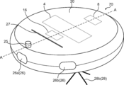
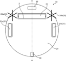
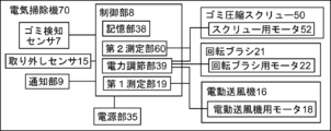
図1は本実施形態の電気掃除機の概略斜視図であり、図2は電気掃除機の概略裏面図であり、図3は、図1、2に示した破線A-Aにおける電気掃除機の概略断面図であり、図4は電気掃除機の電気的構成を示すブロック図である。
本実施形態の電気掃除機70は、吸込口2と、吸込口2から空気を電気掃除機70内に吸引するように設けられた電動送風機16と、吸込口2から吸引した空気中の塵埃10を捕集し溜めるように設けられた集塵部4と、吸込口2から吸引した空気が集塵部4へと流れるように設けられた空気流路3と、空気流路3に設けられたゴミ検知センサ7と、通知部9と、制御部8とを備え、ゴミ検知センサ7は、空気流路3を通過する塵埃10を検出するように設けられ、制御部8は、ゴミ検知センサ7のセンサ出力に基づき空気流路3を通過した塵埃10の量を積算するように設けられ、かつ、空気流路3を通過した塵埃10の積算量が所定の量を超えたと判断すると集塵部5に溜まった塵埃10を捨てる必要があることを通知部9を介してユーザーに通知するように設けられたことを特徴とする。
電気掃除機70は、回転ブラシ21、駆動輪31、電源部35、取り外しセンサ15などを有することができる。
図1は本実施形態の電気掃除機の概略斜視図であり、図2は電気掃除機の概略裏面図であり、図3は、図1、2に示した破線A-Aにおける電気掃除機の概略断面図であり、図4は電気掃除機の電気的構成を示すブロック図である。
本実施形態の電気掃除機70は、吸込口2と、吸込口2から空気を電気掃除機70内に吸引するように設けられた電動送風機16と、吸込口2から吸引した空気中の塵埃10を捕集し溜めるように設けられた集塵部4と、吸込口2から吸引した空気が集塵部4へと流れるように設けられた空気流路3と、空気流路3に設けられたゴミ検知センサ7と、通知部9と、制御部8とを備え、ゴミ検知センサ7は、空気流路3を通過する塵埃10を検出するように設けられ、制御部8は、ゴミ検知センサ7のセンサ出力に基づき空気流路3を通過した塵埃10の量を積算するように設けられ、かつ、空気流路3を通過した塵埃10の積算量が所定の量を超えたと判断すると集塵部5に溜まった塵埃10を捨てる必要があることを通知部9を介してユーザーに通知するように設けられたことを特徴とする。
電気掃除機70は、回転ブラシ21、駆動輪31、電源部35、取り外しセンサ15などを有することができる。
本実施形態の電気掃除機70は、自走式掃除機(ロボット掃除機)であってもよく、スティック型であってもよく、キャニスター型であってもよい。図1~4では、自走式掃除機の例を示している。また、集塵方式は、フィルタ方式であってもよく、紙パック式であってもよく、サイクロン式であってもよい。図1~4に例示した電気掃除機70は、フィルタ方式で集塵する。また、本実施形態の電気掃除機70は、バッテリーを駆動電源とするコードレス掃除機であってもよく、電気コードによりコンセントと接続するコード付掃除機であってもよい。
電動送風機16は、吸気及び排気をする部材であり、ファン17と、ファン17を回転させる電動送風機用モータ18とを備える。また、電動送風機16は、集塵部4の下流側に配置することができる。電動送風機16には、電動送風機用駆動回路などを備えた制御基板が取り付けられていてもよい。電動送風機用モータ18は、カーボンブラシを有するモータであってもよく、ブラシレスモータであってもよい。
電気掃除機70では、電動送風機16のファン17が回転することにより、吸込口2から外気を塵埃10と一緒に電気掃除機70内に吸込み、床面などを掃除することができる。吸込口2から電気掃除機70内に吸い込んだ空気は、空気流路3を流れ集塵部4に流入し、空気と共に吸い込んだ塵埃は集塵部4の内部に集塵され、空気中の塵埃が取り除かれる。集塵部4を通過した後の空気は、排気口27から排出される。
電気掃除機70の吸引力は、制御部8に含まれる電力調節部39により電源部35から電動送風機用モータ18に供給する電力を調節しファン17の回転数を調節することにより制御することができる。
電気掃除機70の吸引力は、制御部8に含まれる電力調節部39により電源部35から電動送風機用モータ18に供給する電力を調節しファン17の回転数を調節することにより制御することができる。
電気掃除機70の集塵方式がフィルタ方式である場合、集塵部4は塵埃10を溜めるダストカップ5及びフィルタ6を有する。電気掃除機70の集塵方式が紙パック方式である場合、集塵部4は紙パックを有する。また、電気掃除機70の集塵方式がサイクロン方式である場合、集塵部4は塵埃10を溜めるダストカップ5及び遠心分離部を有する。
ダストカップ5は、ダストカップ5に溜まった塵埃10を取り除くことができるように設けられる。例えば、ダストカップ5を電気掃除機70から取り外し可能に設けることができる。この場合、塵埃10が溜まったダストカップ5を電気掃除機70から取り外し、ダストカップ5に溜まった塵埃10をゴミ箱に捨て、空になったダストカップ5を再び電気掃除機70に取り付けることによりダストカップ5に溜まった塵埃10を除去することができる。集塵部4は、ダストカップ5の取り外しを検出するように設けられた取り外しセンサ15を有することができる。
ダストカップ5は、ダストカップ5に溜まった塵埃10を取り除くことができるように設けられる。例えば、ダストカップ5を電気掃除機70から取り外し可能に設けることができる。この場合、塵埃10が溜まったダストカップ5を電気掃除機70から取り外し、ダストカップ5に溜まった塵埃10をゴミ箱に捨て、空になったダストカップ5を再び電気掃除機70に取り付けることによりダストカップ5に溜まった塵埃10を除去することができる。集塵部4は、ダストカップ5の取り外しを検出するように設けられた取り外しセンサ15を有することができる。
回転ブラシ21は、床面などを掃除する際に回転するブラシである。回転ブラシ21は、吸込口2に配置することができる。回転する回転ブラシ21により床面などのゴミを掻き出すことができ、掻き出したゴミを吸引口2から吸引することができる。このため、床面などのゴミをしっかりと除去することができる。回転ブラシ21は、回転ブラシ用モータ22により回転するものであってもよく、吸引風により回転するタービンブラシでもよい。
電源部35は、直流電源部であってもよく、交流電源部であってもよい。また、電源部35は、電力線により制御部8と接続し、制御部8の電力調節部39を介して電動送風機16のモータ18、回転ブラシ21を回転させるモータ22、駆動輪31を回転させるモータ32などに電力を供給することができる。電源部35が直流電源部である場合、電源部35はバッテリーを備えることができる。電源部35が交流電源部である場合、電源部35はコンセントから供給される交流電流を利用した電源部とすることができる。
通知部9は、情報をユーザーに通知する部分である。通知部9は制御部8により制御される。通知部9は、例えば、ランプ(LED)、ブザー、スピーカーなどである。また、通知部9は、液晶ディスプレイ、有機ELディスプレイなどの表示部であってもよい。また、通知部9は、スマートフォン、携帯電話などの情報処理端末などと通信する通信部であってもよい。この場合、情報処理端末を介してユーザーに情報が通知される。通知部9はエラー表示として情報をユーザーに通知してもよい。
制御部8は、電気掃除機70を制御する部分である。制御部8は、例えば、CPU、メモリ(記憶部38)、タイマー、入出力ポートなどを有するマイクロコントローラを含むことができる。制御部8に含まれる記憶部38は、マスクROM, EPROM, EEPROM, フラッシュメモリ(不揮発性メモリ)などのROMと、FeRAM, SRAM, DRAMなどのRAMを含むことができる。制御部8は、複数の制御基板から構成されてもよい。これらの複数の制御基板は信号線又は電力線で接続することができる。制御部8は、例えば、ゴミ検知センサ7用制御基板、電動送風機用駆動回路を備えた制御基板、回転ブラシ用駆動回路を備えた制御基板、マイクロコントローラなどから構成される。
制御部8は、電源部35から電動送風機用モータ18、回転ブラシ用モータ22、駆動輪用モータ32などに供給する電力を調節するように設けられた電力調節部39を有することができる。電力調節部39は、例えば、PWM回路、双方向サイリスタを有する位相制御回路などである。
制御部8の記憶部38は、電気掃除機70を制御するための制御ソフトウェアを記憶している。制御ソフトウェアは、ゴミ検知センサ7、電動送風機16、回転ブラシ21、駆動輪31、電源部35、取り外しセンサ15、通知部9などを制御するファームウェアを含むことができる。また、ファームウェアは、ゴミ検知センサ7、電動送風機16、回転ブラシ21、駆動輪31、電源部35、取り外しセンサ15、通知部9などの一部とみなすこともできる。
制御部8は、電動送風機用モータ18の入力電力、入力電流又は回転数を測定するように設けられた第1測定部19を有することができる。第1測定部19は、例えば電流センサを含むことができる。
制御部8の記憶部38は、電気掃除機70を制御するための制御ソフトウェアを記憶している。制御ソフトウェアは、ゴミ検知センサ7、電動送風機16、回転ブラシ21、駆動輪31、電源部35、取り外しセンサ15、通知部9などを制御するファームウェアを含むことができる。また、ファームウェアは、ゴミ検知センサ7、電動送風機16、回転ブラシ21、駆動輪31、電源部35、取り外しセンサ15、通知部9などの一部とみなすこともできる。
制御部8は、電動送風機用モータ18の入力電力、入力電流又は回転数を測定するように設けられた第1測定部19を有することができる。第1測定部19は、例えば電流センサを含むことができる。
ゴミ検知センサ7は、空気流路3を通過する塵埃10を検出するように設けられたセンサである。ゴミ検知センサ7は、制御部8により制御される。ゴミ検知センサ7は、例えば、発光部11と光電変換部12とを有することができる。また、発光部11及び光電変換部12は、電気掃除機70内に吸引した空気及び塵埃10が通過する空気流路3を挟んで対向するように配置され、発光部11が発した光を光電変換部12が受光するように設けられる。本実施形態では、電気掃除機70は発光部11と光電変換部12のペアを1つ有しているが、電気掃除機70は発光部11と光電変換部12のペアを複数有することもできる。発光部11が発光する光は赤外線であってもよい。
電気掃除機70が吸込口2から空気だけを吸い込んでいる場合には、発光部11が発した光は遮られることなく光電変換部12へと届くため、光電変換部12の出力(ゴミ検知センサ7のセンサ出力)は一定となる(このセンサ出力がベースラインとなる)。電気掃除機70が吸込口2から空気とともに塵埃10を吸込み空気流路3を塵埃10が通過すると、発光部11から光電変換部12へと向かう光が塵埃10により遮られ、光電変換部12の出力(ゴミ検知センサ7のセンサ出力)はベースラインから一時的に低下する。なお、ゴミ検知センサ7のセンサ出力は光電変換部12の出力を増幅した出力であってもよい。
制御部8は、このゴミ検知センサ7のセンサ出力のベースラインからの低下の頻度、出力低下量、出力低下時間から吸込口2から吸い込んだ塵埃10の量を算出することができる。また、制御部8は、ゴミ検知センサ7のセンサ出力の低下の頻度、出力低下量又は出力低下時間に基づき、電動送風機16の吸引力又は回転ブラシ21の回転数を変化させることができる。例えば、ゴミ検知センサ7によりより多くの塵埃10を検出した場合には、電動送風機16の吸引力を大きくし、回転ブラシ21の回転数を増加させることができる。このことにより、ゴミの量に応じて電動送風機16の吸引力や回転ブラシ21の回転数を変化させることができ、電気掃除機70が効率よく掃除することが可能になる。
制御部8は、ゴミ検知センサ7のセンサ出力に基づき空気流路3を通過した塵埃10の量を積算するように設けられる。例えば、制御部8は、ゴミ検知センサ7のセンサ出力の低下の頻度、出力低下量又は出力低下時間に基づき空気流路3を通過した塵埃10の量を積算することができる。
空気流路3を通過した塵埃10は集塵部4において捕集され溜まるため、空気流路3を通過した塵埃10の積算量は、集塵部4に溜まった塵埃10の量に対応する。このため、制御部8は、ゴミ検知センサ7のセンサ出力に基づき算出した積算量に基づき集塵部4に溜まった塵埃10の量をモニタリングすることができる。
空気流路3を通過した塵埃10は集塵部4において捕集され溜まるため、空気流路3を通過した塵埃10の積算量は、集塵部4に溜まった塵埃10の量に対応する。このため、制御部8は、ゴミ検知センサ7のセンサ出力に基づき算出した積算量に基づき集塵部4に溜まった塵埃10の量をモニタリングすることができる。
制御部8は、空気流路3を通過した塵埃10の積算量が所定の量を超えたと判断すると集塵部4に溜まった塵埃10を捨てる必要があることを通知部9を介してユーザーに通知するように設けられる。前記所定の量は、集塵部4の満量に対応する量である。このことにより、ユーザーは適切なタイミングで集塵部4に溜まった塵埃10を集塵部4から除去することができ、吸引力の低下などを抑制することができる。
なお、本実施形態では、前記所定の量は、集塵部4の満量に対応する量であるが、集塵部4の4分の3の量に対応する量、集塵部4の満量に対応する量のように複数段階に分けてもよい。通知に際しては、通知部9がランプの色表示で通知する場合、集塵部4に溜まったゴミの量が4分の3未満であれば緑のランプを点灯、集塵部4に溜まったゴミの量が4分の3以上満量未満であれば黄色のランプを点灯、集塵部4に溜まったゴミの量が満了であれば赤のランプを点灯のように色分けすることで、ユーザーに掃除できる目安を示すことができる。
また、本実施形態のように、ダストボックス5が自走式掃除機(ロボット掃除機)の筐体20内に収められている場合、ユーザーが頻繁にダストボックス5の内部を目視することがないため、ダストボックス5内のゴミの量が集塵可能量を超え、ゴミ捨てが必要になった場合にそのことを正確に伝える必要がある。本実施形態では、制御部8は、ゴミ検知センサ7のセンサ出力から算出した積算量に基づき、集塵部4に溜まった塵埃10を捨てる必要があることを通知部9を介してユーザーに通知するため、自走式掃除機であっても、ユーザーは適切なタイミングで集塵部4に溜まった塵埃10を集塵部4から除去することができる。
なお、本実施形態では、前記所定の量は、集塵部4の満量に対応する量であるが、集塵部4の4分の3の量に対応する量、集塵部4の満量に対応する量のように複数段階に分けてもよい。通知に際しては、通知部9がランプの色表示で通知する場合、集塵部4に溜まったゴミの量が4分の3未満であれば緑のランプを点灯、集塵部4に溜まったゴミの量が4分の3以上満量未満であれば黄色のランプを点灯、集塵部4に溜まったゴミの量が満了であれば赤のランプを点灯のように色分けすることで、ユーザーに掃除できる目安を示すことができる。
また、本実施形態のように、ダストボックス5が自走式掃除機(ロボット掃除機)の筐体20内に収められている場合、ユーザーが頻繁にダストボックス5の内部を目視することがないため、ダストボックス5内のゴミの量が集塵可能量を超え、ゴミ捨てが必要になった場合にそのことを正確に伝える必要がある。本実施形態では、制御部8は、ゴミ検知センサ7のセンサ出力から算出した積算量に基づき、集塵部4に溜まった塵埃10を捨てる必要があることを通知部9を介してユーザーに通知するため、自走式掃除機であっても、ユーザーは適切なタイミングで集塵部4に溜まった塵埃10を集塵部4から除去することができる。
制御部8は、ユーザーが集塵部4に溜まった塵埃10を除去すると、ゴミ検知センサ7のセンサ出力に基づき算出した積算量をリセットするように設けられる。制御部8は、例えば、ダストボックス5の取り外しを検出するように設けられた取り外しセンサ15のセンサ出力に基づき、前記積算量をリセットすることができる。
また、積算量をリセットするタイミングは集塵部4が取り外されたことを検出してすぐに行われるのではなく、集塵部4が取り外されてから所定時間以上経過して戻されたときにリセットすることが好ましい。ユーザーが集塵部4に溜まった塵埃量を目視で確認するために、一時的に集塵部4を取り外す可能性があるので、取り外されたことを検出してすぐに積算量をリセットすると、塵埃が捨てられていないにもかかわらず積算量をリセットしてしまう可能性が有る。一時的に目視するだけなので、集塵部4のゴミを捨てる時間に比べると短い場合が多い。そこで、集塵部4が取り外されてから戻されるまでの時間が所定時間未満(例えば15秒)であれば積算量をリセットせず、所定時間以上であれば積算量をリセットする。
また、積算量をリセットするタイミングは集塵部4が取り外されたことを検出してすぐに行われるのではなく、集塵部4が取り外されてから所定時間以上経過して戻されたときにリセットすることが好ましい。ユーザーが集塵部4に溜まった塵埃量を目視で確認するために、一時的に集塵部4を取り外す可能性があるので、取り外されたことを検出してすぐに積算量をリセットすると、塵埃が捨てられていないにもかかわらず積算量をリセットしてしまう可能性が有る。一時的に目視するだけなので、集塵部4のゴミを捨てる時間に比べると短い場合が多い。そこで、集塵部4が取り外されてから戻されるまでの時間が所定時間未満(例えば15秒)であれば積算量をリセットせず、所定時間以上であれば積算量をリセットする。
制御部8は、第1測定部19により測定された電動送風機用モータ18の入力電力、入力電流又は回転数に基づき前記積算量をリセットすることができる。例えば、制御部8は、第1測定部19により測定された電動送風機用モータ18の入力電力、入力電流又は回転数が前回の運転に比べ所定の変化量よりも大きく変化していると判断すると空気流路3を通過した塵埃の積算量をリセットする。
集塵部4に多くの塵埃10が溜まると吸引抵抗が通常よりも高くなり電動送風機用モータ18の入力電力、入力電流が通常値よりも小さくなり、電動送風機用モータ18の回転数が通常値よりも高くなる。集塵部4に溜まった塵埃10が除去されると、電動送風機用モータ18の入力電力、入力電流及び回転数は通常値に戻る。このため、制御部8は、第1測定部19により測定された電動送風機用モータ18の入力電力、入力電流又は回転数に基づき集塵部4の塵埃10の除去を検出することができ、前記積算量をリセットすることができる。
また、制御部8は、取り外しセンサ15のセンサ出力と、第1測定部19により測定された電動送風機用モータ18の入力電力、入力電流又は回転数との両方に基づき前記積算量をリセットすることができる。
例えば、ユーザーが集塵部4に溜まった塵埃量を確認するために、集塵部4を取り外したが、塵埃を捨てずに集塵部4を戻したとする。このとき、集塵部4を取り外しただけでは、積算量はリセットされず、取り外したことを示すフラグAを立てる。その後、電気掃除機70が駆動されて、電動送風機用モータ18の入力電力、入力電流又は回転数が通常値に戻っていることを確認するとフラグBを立てる。フラグAとBとが両方立っていることを確認すると積算量をリセットし、フラグAとBを降ろす。電動送風機用モータ18の入力電力、入力電流又は回転数が通常値に戻っていなければ、塵埃は捨てられていないので、積算量は維持する。
このようにすることで、集塵部4が取り外されただけで塵埃が捨てられていないにも関わらず、積算量がリセットされることを防止することができる。
また、取り外しセンサ15により、集塵部4が取り外されているか否かがわかるので、集塵部4が取り外された状態で掃除が行われることを防止することもできる。
また、制御部8は、取り外しセンサ15のセンサ出力と、第1測定部19により測定された電動送風機用モータ18の入力電力、入力電流又は回転数との両方に基づき前記積算量をリセットすることができる。
例えば、ユーザーが集塵部4に溜まった塵埃量を確認するために、集塵部4を取り外したが、塵埃を捨てずに集塵部4を戻したとする。このとき、集塵部4を取り外しただけでは、積算量はリセットされず、取り外したことを示すフラグAを立てる。その後、電気掃除機70が駆動されて、電動送風機用モータ18の入力電力、入力電流又は回転数が通常値に戻っていることを確認するとフラグBを立てる。フラグAとBとが両方立っていることを確認すると積算量をリセットし、フラグAとBを降ろす。電動送風機用モータ18の入力電力、入力電流又は回転数が通常値に戻っていなければ、塵埃は捨てられていないので、積算量は維持する。
このようにすることで、集塵部4が取り外されただけで塵埃が捨てられていないにも関わらず、積算量がリセットされることを防止することができる。
また、取り外しセンサ15により、集塵部4が取り外されているか否かがわかるので、集塵部4が取り外された状態で掃除が行われることを防止することもできる。
第2実施形態
本実施形態では、集塵部4は、塵埃10を捕集するように設けられたフィルタ6を有する。
また、本実施形態では、制御部8は、ゴミ検知センサ7のセンサ出力に基づき算出された空気流路3を通過した塵埃10の積算量が所定の量(集塵部4の満量)に達していないが第1測定部19により測定された電動送風機用モータ18の入力電力、入力電流又は回転数が正常範囲内にない判断するとフィルタ6を清掃する必要があることを通知部9を介してユーザーに通知するように設けられる。
本実施形態では、集塵部4は、塵埃10を捕集するように設けられたフィルタ6を有する。
また、本実施形態では、制御部8は、ゴミ検知センサ7のセンサ出力に基づき算出された空気流路3を通過した塵埃10の積算量が所定の量(集塵部4の満量)に達していないが第1測定部19により測定された電動送風機用モータ18の入力電力、入力電流又は回転数が正常範囲内にない判断するとフィルタ6を清掃する必要があることを通知部9を介してユーザーに通知するように設けられる。
集塵部4がフィルタ6を有する場合、フィルタ6に慢性的な目詰まりが生じると、集塵部4のゴミが満量となったときと同様に、吸引抵抗が通常よりも高くなり電動送風機用モータ18の入力電力、入力電流が通常値よりも小さくなり、電動送風機用モータ18の回転数が通常値よりも高くなる。
第1測定部19により測定される電動送風機用モータ18の入力電力、入力電流又は回転数だけでは、これらの原因が集塵部4のゴミが満量になったか、又はフィルタ6が目詰まりを起こしたかを判別することは難しい。
第1測定部19により測定される電動送風機用モータ18の入力電力、入力電流又は回転数だけでは、これらの原因が集塵部4のゴミが満量になったか、又はフィルタ6が目詰まりを起こしたかを判別することは難しい。
ゴミ検知センサ7のセンサ出力に基づき算出された空気流路3を通過した塵埃10の積算量から集塵部4のゴミが満量になったか否かを判別することができるため、積算量が所定の量(集塵部4の満量)に達していないが第1測定部19により測定された電動送風機用モータ18の入力電力、入力電流又は回転数が正常範囲内にない場合、フィルタ6に目詰まりが生じた可能性が高い。従って、この場合、制御部8はフィルタ6を清掃する必要があることを通知部9を介してユーザーに通知する。ユーザーは例えば、フィルタ6を電気掃除機70から取り外し、水洗いすることによりフィルタ6に詰まったゴミを取り除き洗浄後のフィルタ6を電気掃除機70に取り付ける。このことにより、フィルタ6の目詰まりを解消することができる。
その他の構成は第1実施形態と同様である。また、第1実施形態についての記載は矛盾がない限り第2実施形態についても当てはまる。
その他の構成は第1実施形態と同様である。また、第1実施形態についての記載は矛盾がない限り第2実施形態についても当てはまる。
第3実施形態
本実施形態では、制御部8は、ゴミ検知センサ7のセンサ出力に基づき算出された空気流路3を通過した塵埃10の積算量が所定の量に達していないが電動送風機16の駆動時間が所定の時間(通常、集塵部4が満量となる駆動時間)を超えたと判断するとゴミ検知センサ7のメンテナンスが必要であることを通知部9を介してユーザーに通知するように設けられる。
本実施形態では、制御部8は、ゴミ検知センサ7のセンサ出力に基づき算出された空気流路3を通過した塵埃10の積算量が所定の量に達していないが電動送風機16の駆動時間が所定の時間(通常、集塵部4が満量となる駆動時間)を超えたと判断するとゴミ検知センサ7のメンテナンスが必要であることを通知部9を介してユーザーに通知するように設けられる。
ゴミ検知センサ7が発光部11と光電変換部12とから構成される場合、発光部11や光電変換部12が汚れると、空気流路3に塵埃10が通過していないときのゴミ検知センサ7のセンサ出力(ベースライン)が低下する。この場合、空気流路3に塵埃10が通過したときのセンサ出力の低下量も少なくなるため、制御部8により算出される空気流路3を通過した塵埃10の積算量が実際よりも少なくなる場合がある。このため、制御部8は、前記積算量が所定の量に達していないが電動送風機16の駆動時間が所定の時間(通常、集塵部4が満量となる駆動時間)を超えたと判断するとゴミ検知センサ7のメンテナンスが必要であることを通知部9を介してユーザーに通知する。また、制御部8は、集塵部4に溜まった塵埃10を捨てる必要があることを通知部9を介してユーザーに通知する。
そして、ユーザーが、集塵部4に溜まった塵埃10を捨て、ゴミ検知センサ7のメンテナンスを行う(例えば、発光部11に付いた汚れや光電変換部12に付いた汚れを取り除く)ことにより、ゴミ検知センサ7の機能を正常化することができる。
その他の構成は第1又は第2実施形態と同様である。また、第1又は第2実施形態についての記載は矛盾がない限り第3実施形態についても当てはまる。
そして、ユーザーが、集塵部4に溜まった塵埃10を捨て、ゴミ検知センサ7のメンテナンスを行う(例えば、発光部11に付いた汚れや光電変換部12に付いた汚れを取り除く)ことにより、ゴミ検知センサ7の機能を正常化することができる。
その他の構成は第1又は第2実施形態と同様である。また、第1又は第2実施形態についての記載は矛盾がない限り第3実施形態についても当てはまる。
第4実施形態
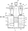
本実施形態の電気掃除機70の集塵部4の集塵方式は、サイクロン式である。図5は、本実施形態の電気掃除機70の電気的構成を示すブロック図であり、図6は、本実施形態の電気掃除機70に含まれる集塵部4の概略断面図である。
本実施形態では、吸込口2から電気掃除機70内に吸引された空気は、ゴミ検知センサ7が設けられた空気流路3を通り、流入口55から第1遠心分離部56に流入する。第1遠心分離部56は、下部にダストボックス5を有し、中心部に内筒51を有する。内筒51の側面には、側面フィルタ53が設けられ、内筒51の下部の外周面にはスクリュー50が設けられている。第1遠心分離部56に流入した空気は、内筒51の外側を下降旋回するように流れた後、内筒51の下側から内筒51の外周面に沿って上方に戻り側面フィルタ53から内筒51の内部に流入する。第1遠心分離部56に流入した空気に含まれる大きな塵埃10は空気が下降旋回することにより生じる遠心力により外側に押し出され、壁面にぶつかり壁伝いに落ちていきダストボックス5に溜まる。スクリュー50は、スクリュー50用モータ52により回転しダストボックス5に溜まった塵埃10を圧縮するように設けられる。このため、ダストボックス5に溜まった塵埃10が空気と共に内筒51の内側に流入することを抑制することができる。図6に示したスクリュー50用モータ52は、集塵部4の内部ユニットごと回転させるように設けられている。
また、制御部8は、スクリュー50用モータ52の入力電流を測定するように設けられた第2測定部60を有する。第2測定部60は、例えば電流センサを有することができる。
本実施形態の電気掃除機70の集塵部4の集塵方式は、サイクロン式である。図5は、本実施形態の電気掃除機70の電気的構成を示すブロック図であり、図6は、本実施形態の電気掃除機70に含まれる集塵部4の概略断面図である。
本実施形態では、吸込口2から電気掃除機70内に吸引された空気は、ゴミ検知センサ7が設けられた空気流路3を通り、流入口55から第1遠心分離部56に流入する。第1遠心分離部56は、下部にダストボックス5を有し、中心部に内筒51を有する。内筒51の側面には、側面フィルタ53が設けられ、内筒51の下部の外周面にはスクリュー50が設けられている。第1遠心分離部56に流入した空気は、内筒51の外側を下降旋回するように流れた後、内筒51の下側から内筒51の外周面に沿って上方に戻り側面フィルタ53から内筒51の内部に流入する。第1遠心分離部56に流入した空気に含まれる大きな塵埃10は空気が下降旋回することにより生じる遠心力により外側に押し出され、壁面にぶつかり壁伝いに落ちていきダストボックス5に溜まる。スクリュー50は、スクリュー50用モータ52により回転しダストボックス5に溜まった塵埃10を圧縮するように設けられる。このため、ダストボックス5に溜まった塵埃10が空気と共に内筒51の内側に流入することを抑制することができる。図6に示したスクリュー50用モータ52は、集塵部4の内部ユニットごと回転させるように設けられている。
また、制御部8は、スクリュー50用モータ52の入力電流を測定するように設けられた第2測定部60を有する。第2測定部60は、例えば電流センサを有することができる。
内筒51の側面フィルタ53を通過して内筒51内に流入した空気は、第2遠心分離部57へと流れる。
第2遠心分離部57では、比較的小さな塵埃10は空気が下降旋回することにより生じる遠心力により外側に押し出され、壁面にぶつかり壁伝いに落ちていき第2遠心分離部57の下部に溜まる。第2遠心分離部57において下降旋回した空気は、第2遠心分離部57の内筒内部に流入し流出口58から流出する。集塵部4は、複数の第2遠心分離部57を有することができる。このことにより、旋回半径を小さくして下降旋回流の角速度を速くすることができ、より小さな塵埃10も除去することが可能になる。図6に示した集塵部4は第2遠心分離部57a、57bの2つの第2遠心分離部を備えている。
なお、集塵部4は、第2遠心分離部57の代わりにフィルタ6を備えてもよい。
第2遠心分離部57では、比較的小さな塵埃10は空気が下降旋回することにより生じる遠心力により外側に押し出され、壁面にぶつかり壁伝いに落ちていき第2遠心分離部57の下部に溜まる。第2遠心分離部57において下降旋回した空気は、第2遠心分離部57の内筒内部に流入し流出口58から流出する。集塵部4は、複数の第2遠心分離部57を有することができる。このことにより、旋回半径を小さくして下降旋回流の角速度を速くすることができ、より小さな塵埃10も除去することが可能になる。図6に示した集塵部4は第2遠心分離部57a、57bの2つの第2遠心分離部を備えている。
なお、集塵部4は、第2遠心分離部57の代わりにフィルタ6を備えてもよい。
制御部8は、空気流路3を通過した塵埃10の積算量が所定の量に達していないが第2測定部60により測定されたスクリュー50用モータ52の入力電流値が所定の値よりも高いと判断すると側面フィルタ53を清掃する必要があることを通知部9を介してユーザーに通知するように設けられる。
ダストボックス5が塵埃10で満量となると、スクリュー50で塵埃10を押し込むために大きな力が必要となるため、スクリュー50用モータ52の入力電流が大きくなる。また、側面フィルタ53に髪の毛などが絡まると、髪の毛などがスクリュー50の回転を妨げるため、スクリュー50用モータ52の入力電流が大きくなる。従って、第2測定部60により測定されるスクリュー50用モータ52の入力電流だけでは、ダストボックス5のゴミ満量と、側面フィルタ53の髪の毛などの絡まりとを判別することが難しい。
ダストボックス5が塵埃10で満量となると、スクリュー50で塵埃10を押し込むために大きな力が必要となるため、スクリュー50用モータ52の入力電流が大きくなる。また、側面フィルタ53に髪の毛などが絡まると、髪の毛などがスクリュー50の回転を妨げるため、スクリュー50用モータ52の入力電流が大きくなる。従って、第2測定部60により測定されるスクリュー50用モータ52の入力電流だけでは、ダストボックス5のゴミ満量と、側面フィルタ53の髪の毛などの絡まりとを判別することが難しい。
ゴミ検知センサ7のセンサ出力に基づき算出された空気流路3を通過した塵埃10の積算量から集塵部4のゴミが満量になったか判別することができるため、積算量が所定の量(集塵部4の満量)に達していないが第2測定部60により測定されたスクリュー50用モータ52の入力電流値が所定の値よりも高い場合、髪の毛などが側面フィルタ53に絡まった可能性が高い。この場合、制御部8は側面フィルタ53を清掃し髪の毛などを除去する必要があることを通知部9を介してユーザーに通知する。ユーザーは例えば、集塵部4のダストカップ5を開けて側面フィルタ53に絡まった髪の毛などを除去することができる。このことにより、側面フィルタ53での髪の毛などの絡まりを解消することができる。
その他の構成は第1~第3実施形態と同様である。また、第1~第3実施形態についての記載は矛盾がない限り第4実施形態についても当てはまる。
その他の構成は第1~第3実施形態と同様である。また、第1~第3実施形態についての記載は矛盾がない限り第4実施形態についても当てはまる。
2:吸込口 3:空気流路 4:集塵部 5:ダストボックス 6:フィルタ 7:ゴミ検知センサ 8:制御部 9:通知部 10:塵埃 11:発光部 12:光電変換部 15:取り外しセンサ 16:電動送風機 17:ファン 18:電動送風機用モータ 19:第1測定部 20:筐体 21:回転ブラシ 22:回転ブラシ用モータ 25:全方位センサ 26、26a、26b:距離センサ 27:排気口 28、28a、28b:サイドブラシ 31、31a、31b:駆動輪 32:駆動輪用モータ 33:前輪 34:後輪 35:電源部 38:記憶部 39:電力調節部 50:スクリュー 51:内筒 52:スクリュー用モータ 53:側面フィルタ 55:流入口 56:第1遠心分離部 57、57a、57b:第2遠心分離部 58:流出口 60:第2測定部 70:電気掃除機
Claims (6)
- 吸込口と、前記吸込口から空気を電気掃除機内に吸引するように設けられた電動送風機と、前記吸込口から吸引した空気中の塵埃を捕集し溜めるように設けられた集塵部と、前記吸込口から吸引した空気が前記集塵部へと流れるように設けられた空気流路と、前記空気流路に設けられたゴミ検知センサと、通知部と、制御部とを備え、
前記ゴミ検知センサは、前記空気流路を通過する塵埃を検出するように設けられ、
前記制御部は、前記ゴミ検知センサのセンサ出力に基づき前記空気流路を通過した塵埃の量を積算するように設けられ、かつ、前記空気流路を通過した塵埃の積算量が所定の量を超えたと判断すると前記通知部を介してユーザーに通知するように設けられたことを特徴とする電気掃除機。 - 前記集塵部は、塵埃が溜まるように設けられたダストボックスと、前記ダストボックスの取り外しを検出するように設けられた取り外しセンサとを有し、
前記制御部は、前記取り外しセンサが前記ダストボックスの取り外しを検出すると前記空気流路を通過した塵埃の積算量をリセットするように設けられた請求項1に記載の電気掃除機。 - 前記電動送風機は、ファン及びそのファンを回転させる第1モータを有し、
前記制御部は、第1モータの入力電力、入力電流又は回転数を測定するように設けられた第1測定部を有し、かつ、第1測定部により測定された第1モータの入力電力、入力電流又は回転数が前回の運転に比べ所定の変化量よりも大きく変化していると判断すると前記空気流路を通過した塵埃の積算量をリセットするように設けられた請求項1又は2に記載の電気掃除機。 - 前記集塵部は、塵埃を捕集するように設けられたフィルタを有し、
前記電動送風機は、ファン及びそのファンを回転させる第1モータを有し、
前記制御部は、第1モータの入力電力、入力電流又は回転数を測定するように設けられた第1測定部を有し、かつ、前記空気流路を通過した塵埃の積算量が所定の量に達していないが第1測定部により測定された第1モータの入力電力、入力電流又は回転数が正常範囲内にないと判断すると前記通知部を介してユーザーに通知するように設けられた請求項1~3のいずれか1つに記載の電気掃除機。 - 前記集塵部は、遠心分離により分離された塵埃が溜まるように設けられたダストボックスと、側面フィルタ及びスクリューを有する内筒と、前記スクリューを回転させるように設けられた第2モータとを備え、
前記スクリューは、前記ダストボックスに溜まった塵埃を圧縮するように設けられ、
前記制御部は、第2モータの入力電流を測定するように設けられた第2測定部を有し、かつ、前記空気流路を通過した塵埃の積算量が所定の量に達していないが第2測定部により測定された第2モータの入力電流値が所定の値よりも高いと判断すると前記側面フィルタを清掃する必要があることを前記通知部を介してユーザーに通知するように設けられた請求項1~4のいずれか1つに記載の電気掃除機。 - 前記制御部は、前記空気流路を通過した塵埃の積算量が所定の量に達していないが前記電動送風機の駆動時間が所定の時間を超えたと判断すると前記通知部を介してユーザーに通知するように設けられた請求項1~5のいずれか1つに記載の電気掃除機。
Applications Claiming Priority (2)
| Application Number | Priority Date | Filing Date | Title |
|---|---|---|---|
| JP2019-015713 | 2019-01-31 | ||
| JP2019015713 | 2019-01-31 |
Publications (1)
| Publication Number | Publication Date |
|---|---|
| WO2020158880A1 true WO2020158880A1 (ja) | 2020-08-06 |
Family
ID=71841427
Family Applications (1)
| Application Number | Title | Priority Date | Filing Date |
|---|---|---|---|
| PCT/JP2020/003494 Ceased WO2020158880A1 (ja) | 2019-01-31 | 2020-01-30 | 電気掃除機 |
Country Status (1)
| Country | Link |
|---|---|
| WO (1) | WO2020158880A1 (ja) |
Cited By (2)
| Publication number | Priority date | Publication date | Assignee | Title |
|---|---|---|---|---|
| ES2911973A1 (es) * | 2020-11-20 | 2022-05-23 | Cecotec Res And Development Sl | Sistema de deposito inteligente para un aparato de limpieza y/o desinfeccion y metodo asociado |
| ES2912047A1 (es) * | 2020-11-23 | 2022-05-24 | Cecotec Res And Development Sl | Sistema de deteccion inteligente de llenado del deposito de un aparato de limpieza y/o desinfeccion y metodo para operarlo |
Citations (4)
| Publication number | Priority date | Publication date | Assignee | Title |
|---|---|---|---|---|
| JP2007275502A (ja) * | 2006-04-12 | 2007-10-25 | Matsushita Electric Ind Co Ltd | 電気掃除機 |
| JP2008220566A (ja) * | 2007-03-12 | 2008-09-25 | Matsushita Electric Ind Co Ltd | 電気掃除機 |
| JP2008301878A (ja) * | 2007-06-05 | 2008-12-18 | Sharp Corp | 電気掃除機 |
| JP2011062229A (ja) * | 2009-09-15 | 2011-03-31 | Toshiba Corp | 電気掃除機 |
-
2020
- 2020-01-30 WO PCT/JP2020/003494 patent/WO2020158880A1/ja not_active Ceased
Patent Citations (4)
| Publication number | Priority date | Publication date | Assignee | Title |
|---|---|---|---|---|
| JP2007275502A (ja) * | 2006-04-12 | 2007-10-25 | Matsushita Electric Ind Co Ltd | 電気掃除機 |
| JP2008220566A (ja) * | 2007-03-12 | 2008-09-25 | Matsushita Electric Ind Co Ltd | 電気掃除機 |
| JP2008301878A (ja) * | 2007-06-05 | 2008-12-18 | Sharp Corp | 電気掃除機 |
| JP2011062229A (ja) * | 2009-09-15 | 2011-03-31 | Toshiba Corp | 電気掃除機 |
Cited By (2)
| Publication number | Priority date | Publication date | Assignee | Title |
|---|---|---|---|---|
| ES2911973A1 (es) * | 2020-11-20 | 2022-05-23 | Cecotec Res And Development Sl | Sistema de deposito inteligente para un aparato de limpieza y/o desinfeccion y metodo asociado |
| ES2912047A1 (es) * | 2020-11-23 | 2022-05-24 | Cecotec Res And Development Sl | Sistema de deteccion inteligente de llenado del deposito de un aparato de limpieza y/o desinfeccion y metodo para operarlo |
Similar Documents
| Publication | Publication Date | Title |
|---|---|---|
| JP5957296B2 (ja) | 充電式電気掃除機 | |
| KR102656583B1 (ko) | 로봇 청소기 | |
| CN104107012B (zh) | 具有机载诊断系统的空气运输器具 | |
| CN1202417C (zh) | 用于吸湿吸尘器的水分指示器 | |
| JP4792476B2 (ja) | フロア掃除装置のための起動信号式自浄フィルター機構 | |
| CN105491930B (zh) | 自走式吸尘器 | |
| JP6012181B2 (ja) | 集塵装置およびそれを備えた自走式掃除機〔7〕 | |
| EP3311721A2 (en) | Vacuum cleaner | |
| JP2015092992A (ja) | 自走式掃除機 | |
| WO2020158880A1 (ja) | 電気掃除機 | |
| TWI584773B (zh) | 電吸塵器 | |
| JP5957135B2 (ja) | 集塵装置およびそれを備えた自走式掃除機 | |
| CN103169429B (zh) | 电动吸尘器 | |
| JP7365795B2 (ja) | 電気掃除機 | |
| JP2019098006A (ja) | 電気掃除機 | |
| JP2016131575A (ja) | 電気掃除機 | |
| CN209153415U (zh) | 一种湿干真空吸尘器 | |
| JP5894701B2 (ja) | 集塵装置およびそれを備えた自走式掃除機 | |
| JP5933090B2 (ja) | 集塵装置およびそれを備えた自走式掃除機 | |
| JP5933100B2 (ja) | 集塵装置およびそれを備えた自走式掃除機 | |
| JP2021186381A (ja) | 電気掃除機 | |
| JP6609452B2 (ja) | 電気掃除機 | |
| JP2008289764A (ja) | 電気掃除機 | |
| CN109717793B (zh) | 电动吸尘器 | |
| JP2021186380A (ja) | 電気掃除機及び目詰まり検知方法 |
Legal Events
| Date | Code | Title | Description |
|---|---|---|---|
| 121 | Ep: the epo has been informed by wipo that ep was designated in this application |
Ref document number: 20748921 Country of ref document: EP Kind code of ref document: A1 |
|
| NENP | Non-entry into the national phase |
Ref country code: DE |
|
| 122 | Ep: pct application non-entry in european phase |
Ref document number: 20748921 Country of ref document: EP Kind code of ref document: A1 |
|
| NENP | Non-entry into the national phase |
Ref country code: JP |