WO2020158074A1 - 過給システム - Google Patents
過給システム Download PDFInfo
- Publication number
- WO2020158074A1 WO2020158074A1 PCT/JP2019/041812 JP2019041812W WO2020158074A1 WO 2020158074 A1 WO2020158074 A1 WO 2020158074A1 JP 2019041812 W JP2019041812 W JP 2019041812W WO 2020158074 A1 WO2020158074 A1 WO 2020158074A1
- Authority
- WO
- WIPO (PCT)
- Prior art keywords
- supercharging
- supercharger
- supercharging mode
- mode
- compressor
- Prior art date
- Legal status (The legal status is an assumption and is not a legal conclusion. Google has not performed a legal analysis and makes no representation as to the accuracy of the status listed.)
- Ceased
Links
Images


Classifications
-
- F—MECHANICAL ENGINEERING; LIGHTING; HEATING; WEAPONS; BLASTING
- F02—COMBUSTION ENGINES; HOT-GAS OR COMBUSTION-PRODUCT ENGINE PLANTS
- F02B—INTERNAL-COMBUSTION PISTON ENGINES; COMBUSTION ENGINES IN GENERAL
- F02B37/00—Engines characterised by provision of pumps driven at least for part of the time by exhaust
-
- F—MECHANICAL ENGINEERING; LIGHTING; HEATING; WEAPONS; BLASTING
- F02—COMBUSTION ENGINES; HOT-GAS OR COMBUSTION-PRODUCT ENGINE PLANTS
- F02B—INTERNAL-COMBUSTION PISTON ENGINES; COMBUSTION ENGINES IN GENERAL
- F02B37/00—Engines characterised by provision of pumps driven at least for part of the time by exhaust
- F02B37/007—Engines characterised by provision of pumps driven at least for part of the time by exhaust with exhaust-driven pumps arranged in parallel, e.g. at least one pump supplying alternatively
-
- F—MECHANICAL ENGINEERING; LIGHTING; HEATING; WEAPONS; BLASTING
- F02—COMBUSTION ENGINES; HOT-GAS OR COMBUSTION-PRODUCT ENGINE PLANTS
- F02B—INTERNAL-COMBUSTION PISTON ENGINES; COMBUSTION ENGINES IN GENERAL
- F02B37/00—Engines characterised by provision of pumps driven at least for part of the time by exhaust
- F02B37/12—Control of the pumps
-
- F—MECHANICAL ENGINEERING; LIGHTING; HEATING; WEAPONS; BLASTING
- F02—COMBUSTION ENGINES; HOT-GAS OR COMBUSTION-PRODUCT ENGINE PLANTS
- F02B—INTERNAL-COMBUSTION PISTON ENGINES; COMBUSTION ENGINES IN GENERAL
- F02B37/00—Engines characterised by provision of pumps driven at least for part of the time by exhaust
- F02B37/12—Control of the pumps
- F02B37/24—Control of the pumps by using pumps or turbines with adjustable guide vanes
-
- F—MECHANICAL ENGINEERING; LIGHTING; HEATING; WEAPONS; BLASTING
- F02—COMBUSTION ENGINES; HOT-GAS OR COMBUSTION-PRODUCT ENGINE PLANTS
- F02D—CONTROLLING COMBUSTION ENGINES
- F02D23/00—Controlling engines characterised by their being supercharged
-
- Y—GENERAL TAGGING OF NEW TECHNOLOGICAL DEVELOPMENTS; GENERAL TAGGING OF CROSS-SECTIONAL TECHNOLOGIES SPANNING OVER SEVERAL SECTIONS OF THE IPC; TECHNICAL SUBJECTS COVERED BY FORMER USPC CROSS-REFERENCE ART COLLECTIONS [XRACs] AND DIGESTS
- Y02—TECHNOLOGIES OR APPLICATIONS FOR MITIGATION OR ADAPTATION AGAINST CLIMATE CHANGE
- Y02T—CLIMATE CHANGE MITIGATION TECHNOLOGIES RELATED TO TRANSPORTATION
- Y02T10/00—Road transport of goods or passengers
- Y02T10/10—Internal combustion engine [ICE] based vehicles
- Y02T10/12—Improving ICE efficiencies
Definitions
- This disclosure relates to a supercharging system, and particularly to a supercharging system having a plurality of superchargers connected in parallel.
- Patent Document 1 there was a supercharging system having two superchargers connected in parallel (see, for example, Patent Document 1).
- a single supercharging mode in which one supercharger supercharges the intake air of the engine according to the load of the engine and a twin supercharging mode in which two superchargers supercharge the intake air of the engine are used. Switch between feeding mode.
- the twin supercharge mode is used to drive the primary supercharger and the secondary supercharger. This is because two superchargers realize a high supercharging pressure in a speed range where exhaust energy is large.
- Patent Document 1 discloses a characteristic technique in switching from the single supercharging mode to the twin supercharging mode. However, Patent Document 1 does not disclose a characteristic technique of switching from the twin supercharging mode to the single supercharging mode. As described above, conventionally, a characteristic technique for switching from the twin supercharging mode to the single supercharging mode has not been considered so much. In the technique often used, the twin supercharging mode is switched to the single supercharging mode according to the engine speed and the load (fuel injection amount).
- FIG. 14 is a diagram for explaining switching from the conventional twin supercharging mode to the single supercharging mode.
- FIG. 14A shows a change in the rotation speed of the engine.
- FIG. 14B shows the change in the fuel injection amount.
- FIG. 14C shows a change in supercharging pressure.
- the target supercharging pressure which is determined by the engine speed and the fuel injection amount, also drops at once.
- the target supercharging pressure there is a delay in the decrease of the actual supercharging pressure, and the actual supercharging pressure gradually decreases.Therefore, there is a difference between the target supercharging pressure determined by the engine speed and the fuel injection amount and the actual supercharging pressure. Occurs. For this reason, switching from the twin supercharging mode to the single supercharging mode according to the engine speed and the fuel injection amount corresponds to the transient state in which the engine speed and the fuel injection amount are changing. Can not.
- This disclosure has been made to solve the above problems, and an object thereof is to provide a supercharging system capable of appropriately switching from a twin supercharging mode to a single supercharging mode even in a transient situation. Is to provide.
- a supercharging system includes a first turbine driven by exhaust gas discharged from an engine, a first variable nozzle mechanism that adjusts a flow velocity of exhaust gas flowing into the first turbine by an opening degree, and intake air to the engine.
- a first supercharger including a first compressor for supercharging, a second turbine driven by exhaust gas discharged from an engine, and a second variable nozzle for adjusting a flow rate of exhaust gas flowing into the second turbine by an opening degree.
- a second supercharger including a mechanism for supercharging intake air to the engine, a single supercharge mode in which air supercharged in the first supercharger is supplied to the engine, and a supercharger in the first supercharger.
- the compressor map includes a first axis of the amount of air taken into the first compressor of the first supercharger and a second axis of the pressure ratio of the discharge pressure to the suction pressure of the first compressor.
- the operating point specified by the pressure ratio and the air amount in the compressor map stored in the storage unit may be below a predetermined line on the compressor map. If indicated, switch supercharging mode to single supercharging mode.
- the predetermined line has a region where the pressure ratio increases faster in the twin supercharging mode than in the single supercharging mode when the fuel injection is restarted in the engine, and in the single supercharging mode compared to the twin supercharging mode.
- the mode is the boundary with the region where the pressure ratio rises faster.
- the predetermined line is a line of constant rotation speed during steady running of the first supercharger.
- the control device controls the first supercharger and the second supercharger to obtain the target supercharging pressure when the operating point is not lower than the predetermined line when the twin supercharging mode is switched.
- the required target opening amounts of the first variable nozzle mechanism and the second variable nozzle mechanism are calculated from the state quantities of the intake passage and the exhaust passage, and when the calculated target opening amounts are out of the controllable range, the supercharging mode is set. Switch to single supercharging mode.
- FIG. 1 It is a figure which shows an example of a compressor operation map which shows the relationship between the intake air amount of the compressor of a primary supercharger, and the pressure ratio before and behind a compressor. It is a figure for demonstrating the change of the supercharging pressure by the re-acceleration when the operating point of the compressor operation map has reached
- FIG. 1 is a diagram showing an example of a schematic configuration of an engine 1 in this embodiment.
- this engine 1 is mounted in a vehicle as a drive source for traveling, for example.
- engine 1 is described as an example of a diesel engine, but may be, for example, a gasoline engine.
- the engine 1 includes banks 10A and 10B, an air cleaner 20, an intercooler 25, intake manifolds 28A and 28B, a primary supercharger 30, a secondary supercharger 40, and exhaust manifolds 50A and 50B (hereinafter referred to as "exhaust manifold"). (Also referred to as a), an exhaust treatment device 81, and a control device 200.
- a plurality of cylinders 12A are formed in the bank 10A.
- a plurality of cylinders 12B are formed in the bank 10B.
- a piston (not shown) is housed in each cylinder 12A, 12B, and a combustion chamber (space in which fuel burns) is formed by the top of the piston and the inner wall of the cylinder. The volume of the combustion chamber is changed as the piston slides in each cylinder 12A, 12B.
- An injector (not shown) is provided in each of the cylinders 12A and 12B, and during operation of the engine 1, fuel of a timing and an amount set by the control device 200 is injected into each of the cylinders 12A and 12B. ..
- the injection amount and timing of the fuel injected from each injector are set by the control device 200 based on, for example, the engine speed, the intake air amount Ga, the accelerator pedal depression amount, the vehicle speed, and the like.
- the pistons of the cylinders 12A and 12B are connected to a common crankshaft (not shown) via a connecting rod.
- the combustion of fuel in the cylinders 12A and 12B in a predetermined order causes the piston to slide in the cylinders 12A and 12B, and the vertical movement of the piston is converted into the rotational movement of the crankshaft via the connecting rod. ..
- the primary supercharger 30 (first supercharger) is a turbocharger including a compressor 31 (first compressor) and a turbine 32 (first turbine).
- the compressor 31 of the primary supercharger 30 is provided in the intake passage of the engine 1 (that is, the passage from the air cleaner 20 to the intake manifolds 28A and 28B).
- the turbine 32 of the primary supercharger 30 is provided in the exhaust passage of the engine 1 (that is, the passage from the exhaust manifolds 50A and 50B to the exhaust treatment device 81).
- a compressor wheel 33 is rotatably housed in the compressor 31. Inside the turbine 32, a turbine wheel 34 and a variable nozzle mechanism 35 are provided. The turbine wheel 34 is rotatably housed in the turbine 32. The compressor wheel 33 and the turbine wheel 34 are connected by a rotating shaft 36 and rotate integrally. The compressor wheel 33 is rotationally driven by the energy of the exhaust gas (exhaust gas energy) supplied to the turbine wheel 34.
- the variable nozzle mechanism 35 (first variable nozzle mechanism) changes the flow velocity of the exhaust gas that operates the turbine 32.
- the variable nozzle mechanism 35 is arranged on the outer peripheral side of the turbine wheel 34, and rotates each of the plurality of nozzle vanes (not shown) that guides the exhaust gas supplied from the exhaust gas inlet to the turbine wheel 34, and the plurality of nozzle vanes.
- a drive device (not shown) that changes a gap between adjacent nozzle vanes (this gap is referred to as a VN opening degree in the following description).
- the variable nozzle mechanism 35 changes the VN opening degree by rotating a nozzle vane using a drive device in response to a control signal VN1 from the control device 200, for example.
- the secondary supercharger 40 (second supercharger) is a turbocharger including a compressor 41 and a turbine 42 (second turbine).
- the secondary supercharger 40 has the same structure and size as the primary supercharger 30.
- the compressor 41 of the secondary supercharger 40 is provided in the intake passage of the engine 1 in parallel with the compressor 31, and supercharges the intake air of the engine 1.
- the turbine 42 of the secondary supercharger 40 is provided in parallel with the turbine 32 in the exhaust passage of the engine 1.
- a compressor wheel 43 is rotatably housed in the compressor 41.
- a turbine wheel 44 and a variable nozzle mechanism 45 are provided in the turbine 42.
- the turbine wheel 44 is rotatably housed in the turbine 42.
- the compressor wheel 43 and the turbine wheel 44 are connected by a rotating shaft 46 and rotate integrally.
- the compressor wheel 43 is rotationally driven by the exhaust energy supplied to the turbine wheel 44.
- variable nozzle mechanism 45 Since variable nozzle mechanism 45 has the same configuration as variable nozzle mechanism 35, detailed description thereof will not be repeated.
- the variable nozzle mechanism 45 changes the VN opening degree, for example, by rotating the nozzle vane using a drive device in response to a control signal VN2 from the control device 200.
- the air cleaner 20 removes foreign matter from the air taken in from an intake port (not shown).
- One end of the intake pipe 23 is connected to the air cleaner 20.
- the other end of the intake pipe 23 is branched and connected to one end of the intake pipe 21 and one end of the intake pipe 22.
- the other end of the intake pipe 21 is connected to the intake inlet of the compressor 31 of the primary supercharger 30.
- One end of the intake pipe 37 is connected to the intake air outlet of the compressor 31 of the primary supercharger 30.
- the other end of the intake pipe 37 is connected to the intercooler 25.
- the compressor 31 supercharges the air sucked through the intake pipe 21 by the rotation of the compressor wheel 33 and supplies the supercharged air to the intake pipe 37.
- the other end of the intake pipe 22 is connected to the intake inlet of the compressor 41 of the secondary supercharger 40.
- One end of an intake pipe 47 is connected to the intake air outlet of the compressor 41 of the secondary supercharger 40.
- the other end of the intake pipe 47 is connected to the connecting portion C3 in the middle of the intake pipe 37.
- the compressor 41 supercharges the air taken in through the intake pipe 22 by the rotation of the compressor wheel 43 and supplies the supercharged air to the intake pipe 47.
- a first control valve 62 is provided in the middle of the intake pipe 47.
- the first control valve 62 is, for example, a normally-off VSV (negative pressure switching valve) that is ON (open)/OFF (closed) controlled according to a control signal CV1 from the control device 200.
- VSV negative pressure switching valve
- one end of the recirculation pipe 48 is connected to the connecting portion C4 located on the upstream side (the compressor 41 side) of the first control valve 62 in the intake pipe 47.
- the other end of the return pipe 48 is connected to the intake pipe 21.
- the recirculation pipe 48 is a passage for recirculating at least a part of the air flowing through the intake pipe 47 to the upstream side of the compressor 31 of the primary supercharger 30. The air recirculated to the intake pipe 21 through the recirculation pipe 48 is supplied to the compressor 31.
- a second control valve 64 is provided in the middle of the reflux pipe 48.
- the second control valve 64 is, for example, a normally-off electromagnetic valve (solenoid valve) that is ON (open)/OFF (closed) controlled according to a control signal CV2 from the control device 200.
- the air supercharged by the compressor 31 and the air supercharged by the compressor 41 and passing through the first control valve 62 are supplied to the connecting portion C3. These air merges at the connecting portion C3 and flows into the intercooler 25.
- the intercooler 25 is configured to cool the inflowing air.
- the intercooler 25 is, for example, an air-cooled or water-cooled heat exchanger.
- One end of the intake pipe 27A and one end of the intake pipe 27B are connected to the intake air outlet of the intercooler 25 via a diesel throttle 68.
- the diesel throttle 68 is configured so that its opening can be adjusted using an electric actuator, and adjusts the flow rate of intake air according to a control signal from the control device 200.
- the other end of the intake pipe 27A is connected to the intake manifold 28A.
- the other end of the intake pipe 27B is connected to the intake manifold 28B.
- the intake manifolds 28A and 28B are connected to intake ports (not shown) of the cylinders 12A and 12B in the banks 10A and 10B, respectively.
- the exhaust manifolds 50A and 50B are connected to the exhaust ports (not shown) of the cylinders 12A and 12B in the banks 10A and 10B, respectively.
- Exhaust gas (gas after combustion) discharged from the combustion chamber of each cylinder 12A, 12B to the outside of the cylinder through the exhaust port is discharged to the outside via the exhaust passage of the engine 1.
- the exhaust passage includes exhaust manifolds 50A and 50B, exhaust pipes 51A and 51B, a connecting portion C1, exhaust pipes 52A, 52B, 53A and 53B, and a connecting portion C2.
- One end of the exhaust pipe 51A is connected to the exhaust manifold 50A.
- One end of the exhaust pipe 51B is connected to the exhaust manifold 50B.
- the other end of the exhaust pipe 51A and the other end of the exhaust pipe 51B join together at the connection portion C1 and then branch to be connected to one end of the exhaust pipe 52A and one end of the exhaust pipe 52B.
- the other end of the exhaust pipe 52A is connected to the exhaust inlet of the turbine 32.
- One end of the exhaust pipe 53A is connected to the exhaust outlet of the turbine 32.
- the other end of the exhaust pipe 52B is connected to the exhaust inlet of the turbine 42.
- One end of an exhaust pipe 53B is connected to the exhaust outlet of the turbine 42.
- a third control valve 66 is provided in the middle of the exhaust pipe 52B.
- the third control valve 66 is, for example, a normally-on VSV (negative pressure switching valve) that is ON (open)/OFF (closed) controlled according to a control signal CV3 from the control device 200.
- the other end of the exhaust pipe 53A and the other end of the exhaust pipe 53B meet at the connecting portion C2 and are connected to the exhaust treatment device 81.
- the exhaust treatment device 81 is composed of, for example, an SCR catalyst, an oxidation catalyst, a PM removal filter, or the like, and purifies the exhaust gas flowing from the exhaust pipe 53A and the exhaust pipe 53B.
- the operation of the engine 1 is controlled by the control device 200.
- the control device 200 includes a CPU (Central Processing Unit) that performs various types of processing, a ROM (Read Only Memory) that stores programs and data, and a memory (memory that stores RAM (Random Access Memory), etc. that stores the processing results of the CPU, etc. Section) and an input/output port (both not shown) for exchanging information with the outside.
- Various sensors for example, the air flow meter 102, the first pressure sensor 106, the second pressure sensor 108, etc.
- Devices to be controlled for example, a plurality of injectors, variable nozzle mechanisms 35 and 45, first control valve 62, second control valve 64, third control valve 66, etc.
- the output port for example, a plurality of injectors, variable nozzle mechanisms 35 and 45, first control valve 62, second control valve 64, third control valve 66, etc.
- the control device 200 controls various devices so that the engine 1 is in a desired operating state based on signals from each sensor and devices and maps and programs stored in the memory.
- the various controls are not limited to the processing by software, and may be processed by dedicated hardware (electronic circuit). Further, the control device 200 has a built-in timer circuit (not shown) for measuring time.
- the air flow meter 102 detects the intake air amount Ga.
- the air flow meter 102 transmits a signal indicating the detected intake air amount Ga to the control device 200.
- the engine speed sensor detects the engine speed.
- the engine speed sensor sends a signal indicating the detected engine speed to the control device 200.
- the first pressure sensor 106 detects the pressure (hereinafter, referred to as the first supercharging pressure) Pp at the connecting portion C3 of the intake pipe 37.
- the first pressure sensor 106 transmits a signal indicating the detected first boost pressure Pp to the control device 200.
- the second pressure sensor 108 detects the pressure at the connection portion C4 of the intake pipe 47 (hereinafter, referred to as the second supercharging pressure Ps).
- the second pressure sensor 108 transmits a signal indicating the second boost pressure Ps to the control device 200.
- the primary supercharger 30, the secondary supercharger 40, and the control device 200 constitute a “supercharging system”.
- the control device 200 controls the first control valve 62, the second control valve 64, and the third control valve 66 to perform a single supercharging mode in which supercharging is performed only by the primary supercharger 30 (primary turbo), and a primary supercharging mode.
- a switching control for switching from one of the supercharger 30 (primary turbo) and the twin supercharger 40 (secondary turbo) to the other is carried out.
- the control device 200 executes the operation in the approach mode in which the supercharging pressure by the secondary supercharger 40 is increased above a certain level from the single supercharging mode. After that, the supercharging mode is switched to the twin supercharging mode.
- Control device 200 operates the supercharging system in the single supercharging mode when a predetermined execution condition is satisfied.
- the predetermined execution condition includes, for example, a condition that the operating state of the engine 1 based on the engine speed and the intake air amount Ga is a low load operating state.
- control device 200 closes all of first control valve 62, second control valve 64, and third control valve 66 (off state).
- FIG. 2 is a diagram for explaining the operation of the supercharging system in the single supercharging mode.
- the exhaust gas flowing through the exhaust manifolds 50A and 50B flows to the turbine 32 of the primary supercharger 30 via the exhaust pipe 52A, and to the exhaust treatment device 81 via the exhaust pipe 53A.
- the exhaust gas supplied to the turbine 32 causes the turbine wheel 34 to rotate, and the compressor wheel 33 also rotates as the turbine wheel 34 rotates.
- the air sucked from the air cleaner 20 flows into the compressor 31 via the intake pipe 23 and the intake pipe 21.
- the intake air discharged from the compressor 31 flows into the intercooler 25 via the intake pipe 37.
- the intake air that has flowed into the intercooler 25 branches into the intake pipes 27A and 27B and flows into each of the intake manifolds 28A and 28B.
- Control device 200 switches from the single supercharging mode to the twin supercharging mode when, for example, the supercharging mode is the single supercharging mode and the rotation speed of primary supercharger 30 exceeds the threshold value. Judge that there is a request.
- the control device 200 executes the run-up mode before switching to the twin supercharging mode. That is, the control device 200 puts both the second control valve 64 and the third control valve 66 into an open state (ON state) and puts the first control valve 62 into a closed state (OFF state).
- FIG. 3 is a diagram for explaining the operation of the supercharging system in the run-up mode.
- the exhaust gas flowing through the exhaust manifolds 50A and 50B once joins at the connection portion C1 and then branches into the exhaust pipes 52A and 52B, and the turbines of the primary supercharger 30 and the secondary supercharger 40 are discharged. It flows into both 32 and 42, and flows into the exhaust treatment device 81 via the exhaust pipes 53A and 53B.
- the turbine wheel 34 is rotated by the exhaust gas supplied to the turbine 32, and the compressor wheel 33 is rotated along with the rotation of the turbine wheel 34.
- the turbine wheel 44 is rotated by the exhaust gas supplied to the turbine 42, and the compressor wheel 43 is rotated with the rotation of the turbine wheel 44.
- the air taken in from the air cleaner 20 branches from the intake pipe 23 into the intake pipes 21 and 22 and flows into both the compressors 31 and 41.
- the intake air discharged from the compressor 31 flows into the intercooler 25 via the intake pipe 37.
- the intake air discharged from the compressor 41 flows from the intake pipe 47 to the recirculation pipe 48 via the connecting portion C4 and from the recirculation pipe 48 to the compressor 31 via the intake pipe 21.
- the intake air that has flowed into the intercooler 25 branches into the intake pipes 27A and 27B and flows into each of the intake manifolds 28A and 28B.
- the rotational speed of the secondary supercharger 40 is increased while supercharging the intake air flowing to the intercooler 25 by the primary supercharger 30.
- the pressure of the intake air discharged from the compressor 41 of the secondary supercharger 40 increases.
- the control device 200 operates the supercharging system in the twin supercharging mode at the timing when the supercharging ability of the secondary supercharger 40 in the approach mode becomes sufficiently high.
- the control device 200 sets the first control valve 62 to the open state (on state) and the second control valve 64 to the closed state (off state). 3
- the control valve 66 is opened (on).
- FIG. 4 is a diagram for explaining the operation of the supercharging system in the twin supercharging mode.
- the intake air discharged from the compressor 41 of the secondary supercharger 40 was flowing from the middle of the intake pipe 47 to the intake pipe 21 via the recirculation pipe 48, whereas in the twin supercharge mode.
- the intake air discharged from the compressor 41 of the secondary supercharger 40 flows from the intake pipe 47 to the intercooler 25 via the intake pipe 37 as shown by the arrow in FIG.
- the twin supercharging mode is switched to the single supercharging mode according to the engine speed and the load (fuel injection amount).
- the engine speed and the fuel injection amount are changing. It cannot handle transient conditions.
- the control device 200 controls the variable nozzles necessary for the primary supercharger 30 and the secondary supercharger 40 to obtain the target supercharging pressure when the twin supercharging mode is switched.
- the target VN opening degree (target opening degree) of the mechanism 35 and the variable nozzle mechanism 45 is calculated from the state quantities of the intake path and the exhaust path, and when the calculated target VN opening degree is out of the controllable range, the supercharging mode is set. Switch to single supercharging mode. As a result, the twin supercharging mode can be appropriately switched to the single supercharging mode even in a transient situation.
- the memory of the control device 200 stores data indicating a compressor map indicating the characteristics of the first compressor.
- the compressor map includes a first axis of the amount of air taken into the first compressor of the first supercharger and a second axis of the pressure ratio of the discharge pressure to the suction pressure of the first compressor.
- FIG. 5 is a flowchart showing an example of the flow of a process of switching to the single supercharging mode in this embodiment.
- control device 200 determines whether or not the supercharging mode flag is a value indicating the twin supercharging mode (step S111).
- the supercharging mode flag is a flag that indicates the supercharging mode that is currently being controlled, and is a value that indicates one of the single supercharging mode, the twin supercharging mode, and the run-up mode as the controlled supercharging mode. Can be taken.
- control device 200 When it is determined that the supercharging mode flag does not indicate the twin supercharging mode (NO in step S111), the control device 200 returns the process to be executed to the process of the calling source of this process.
- the control device 200 calculates the target VN opening degree from the state quantity of each part using the physical formula of the supercharger. (Step S112).
- the state quantities of the intake path and the exhaust path when calculating the target VN opening degree are the state quantity of the intake path before branching to the primary supercharger 30 and the secondary supercharger 40, and the primary supercharger, respectively.
- the state quantity of the exhaust path after joining from 30 and the secondary supercharger 40 is used.
- FIG. 6 is a first diagram for explaining the physical formula of the supercharger.
- the target post-compressor pressure P3 is calculated from the target diesel throttle pre-pressure and the intercooler pressure loss.
- the target diesel throttle pre-pressure is a target pressure between the diesel throttle 68 and the intercooler 25.
- the intercooler pressure loss is the pressure loss due to the intercooler 25.
- the target post-compressor pressure P3 is calculated by adding the intercooler pressure loss to the target diesel throttle pre-pressure (hereinafter referred to as "target D slot pre-pressure").
- the target compressor work is calculated using the formula (1) from the target post-compressor pressure P3, the intake air amount Ga, the intake air temperature Tha, and the pre-compressor pressure P2.
- Cpa is a constant temperature specific heat (0.24)
- k is a specific heat ratio of air (1.4).
- the intake air amount Ga is specified according to the detection signal from the air flow meter 102.
- the target turbine work is calculated using the formula (2) from the target compressor work and the total turbo efficiency ⁇ tot.
- the total turbo efficiency ⁇ tot is calculated by the control device 200 from the state quantity using a known calculation formula.
- the target exhaust manifold pressure is calculated using the formula (3) from the target turbine work, the exhaust gas temperature T4, the turbo post pressure P6, and the turbine passing gas amount Ga+Gf.
- Cpg is a constant pressure specific heat (0.26)
- K is a specific heat ratio of exhaust gas (1.33).
- the mass flow rate Gf of the injected fuel is calculated from the fuel injection amount calculated by the control device 200 for the fuel injection.
- FIG. 7 is a second diagram for explaining the physical formula of the supercharger.
- the target exhaust pressure P4 is subject to a constraint guard.
- P4 when the target exhaust manifold pressure P4 is higher than the limited exhaust manifold pressure, P4 is set as the limited exhaust manifold pressure.
- the limit exhaust manifold pressure is predetermined as a value that does not blow through the oil seal of the valve stem of the exhaust valve or open the exhaust valve.
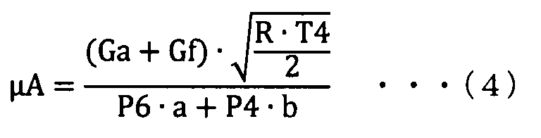
- the target effective opening area ⁇ A is calculated from the target exhaust manifold pressure P4, the exhaust manifold gas temperature T4, the turbo post pressure P6, and the turbine passing gas amount Ga+Gf using the nozzle formula of Formula (4). It should be noted that A: actual opening area, ⁇ A: target effective opening area, R: gas constant (287), a, b: P6/P4 are constants determined in advance for each value.
- the target VN opening is calculated from the calculated target effective opening area ⁇ A using the opening characteristic map showing the relationship between the VN opening and the effective opening area.
- the control device 200 determines whether the calculated target VN opening is outside the controllable range (step S113). Due to the structure of the nozzle vane, the VN opening cannot be controlled in a completely closed state (100%) or a completely opened state (0%). Therefore, the controllable range of the VN opening is, for example, a range of 10% to 96%. When it is determined that the calculated target VN opening is out of the controllable range (YES in step S113), the control device 200 continues the state in which the target VN opening is out of the controllable range for a predetermined period. It is determined whether or not (step S114).
- control device 200 When it is determined that the operation has continued for the predetermined period (YES in step S114), control device 200 changes the supercharging mode flag to a value indicating the single supercharging mode (step S117), and executes the processing of this processing. Return to the calling process. As a result, the mode is switched to the single supercharging mode.
- FIG. 8 is a diagram for explaining an example of a change in the target VN opening calculated by a physical formula.
- the accelerator is turned off as shown in FIG. 8(B) and the fuel injection amount is drastically reduced, the engine is turned off as shown in FIG. 8(A).
- the rotation speed of 1 gradually decreases.
- the target VN opening for determination calculated by the above-described physical formula also decreases, but if the target supercharging pressure exceeds the actual supercharging pressure at time T1, the target VN opening for determination increases.
- the target VN opening continues for a predetermined period in a state where the target VN opening exceeds the predetermined upper limit value on the closing side of the controllable range, and at time T2, the supercharging mode is switched from the twin supercharging mode to the single supercharging mode.
- the control device 200 determines that the intake air amount Ga of the primary supercharger 30 is equal to the post-compressor pressure P3 with respect to the pre-compressor pressure P2 of the primary supercharger 30. It is determined whether or not the threshold value is less than or equal to the threshold value calculated from the pressure ratio (step S115).
- FIG. 9 is a diagram showing an example of a compressor operation map (compressor map) showing the relationship between the intake air amount of the compressor 31 of the primary supercharger 30 and the pressure ratio before and after the compressor 31.
- the compressor operation map is a map showing an operation region of compressor 31 with the intake air amount and pressure ratio of compressor 31 of primary supercharger 30 as parameters.
- the horizontal axis and the vertical axis of this map represent the intake air amount and the pressure ratio of the compressor 31, respectively.
- the intake air amount of the compressor 31 can be estimated from the intake air amount detected by the air flow meter 102, for example.
- “Surge line” (two-dot chain line) indicates a boundary line with the surge region where surging is likely to occur in the primary supercharger 30.
- the “uniform rotation speed line” (thin solid line) is a line group in which operating points having the same rotation speed of the compressor 31 are connected to each other for each rotation speed of the compressor 31.
- the rotation speed of the compressor 31 becomes higher as the intake air amount of the compressor 31 increases and the pressure ratio increases. Further, the rotation speed of the compressor 31 becomes higher as the engine rotation speed becomes higher during the single supercharging mode.
- Switch line L2 is the line that switches from single supercharging mode to twin supercharging mode. At the time of acceleration, when the operating point of the compressor 31 moves along the operating line shown in FIG. 9 and reaches the switching line L2, it is switched to the pre-running mode of the preparatory stage for switching from the single supercharging mode to the twin supercharging mode, and thereafter. , Switch to twin supercharging mode.
- Switch line L1 is the line that switches from the twin supercharging mode to the single supercharging mode.
- the switching line L1 corresponds to the predetermined line in the present invention. At the time of deceleration, when the operating point of the compressor 31 moves along the operating line shown in FIG. 9 and reaches the switching line L1, the twin supercharging mode is switched to the single supercharging mode.
- the control device 200 changes the supercharging mode flag to a value indicating the single supercharging mode (step S117), and returns the processing to be executed to the calling processing of this processing. As a result, the mode is switched to the single supercharging mode.
- control device. 200 returns the processing to be executed to the calling processing of this processing while keeping the supercharging mode flag at the value indicating the twin supercharging mode (step S116).
- FIG. 10 is a diagram for explaining changes in supercharging pressure due to reacceleration when the operating point of the compressor operation map reaches the switching line L1 and when it does not.
- the accelerator opening is reduced from 100% to 20% as shown in FIG. 10(A)
- the target supercharging pressure is rapidly increased as shown in FIG. 10(B).
- the actual supercharging pressure gradually decreases.
- the twin supercharging mode is switched to the single supercharging mode.
- the thick broken line in (I) of FIG. 10 at time T2 immediately before time T3, when the accelerator is re-accelerated with the accelerator opening being 100%, the operating point is before reaching the switching line L1. Responsiveness of supercharging pressure is good even in the supply mode.
- FIG. 11 is a diagram for explaining the difference in the operating point depending on the accelerator opening degree in the steady state on the compressor operation map.
- the accelerator opening is indicated by A1% to A5%, and A1>A2>A3>A4>A5.
- the operating point moves in the upper right direction in which the intake air amount and the pressure ratio P3/P2 are higher as the accelerator opening is larger in the steady state.
- the operating point of accelerator opening A3% is on the switching line L1.
- the operating point of the accelerator opening A4% is a position below the switching line L1.
- FIG. 12 is a diagram for explaining the difference in supercharging pressure during reacceleration for each accelerator opening after deceleration.
- the post-compressor pressure P3 is increased as indicated by the thick solid line. rises.
- the post-compressor pressure P3 increases as indicated by the thick broken line.
- the responsiveness of the supercharging pressure after switching to the single supercharging mode is higher than that in the twin supercharging mode. Is good.
- the post-compressor pressure P3 is After being raised to some extent, the second control valve 64 is switched to the open state, and after the approach mode is set, the first control valve 62 is switched to the open state, thereby switching to the twin supercharging mode.
- the equal rotation speed line can be defined as the switching line L1.
- FIG. 13 is a diagram for explaining calculation of the target VN opening degree in the modified example.
- the target VN opening degree is calculated by the physical formula described in FIGS. 6 and 7, the target VN opening degree is rapidly calculated as a value on the closing side.
- the determination of the target VN opening degree in step S113 of FIG. 5 becomes unstable.
- the target supercharging pressure may be smoothed to be used for the calculation of the target VN opening. This makes it possible to stabilize the determination of the target VN opening degree.
- an intake throttle valve or an EGR (Exhaust Gas Recirculation) gas inlet of an exhaust gas recirculation device may be provided.
- the engine 1 has been described as an example of a V6 cylinder engine, but it may be, for example, another cylinder layout (for example, inline or horizontal) engine.
- the supercharging system has been described as having two superchargers, but it may have three or more superchargers.
- a supercharging system including a primary supercharger 30, a secondary supercharger 40, and a control device 200, disclosure of an internal combustion engine such as engine 1, internal combustion such as engine 1 It can be regarded as disclosure of a control device such as the ECU 100 of the engine, disclosure of a control method by such a control device, or disclosure of an internal combustion engine system including such an internal combustion engine and a control device.
- the supercharging system adjusts the turbine 32 driven by the exhaust gas discharged from the engine 1 and the flow velocity of the exhaust gas flowing into the turbine 32 according to the opening degree.
- a primary supercharger 30 including a variable nozzle mechanism 35 and a compressor 31 for supercharging intake air to the engine 1, a turbine 42 driven by exhaust gas discharged from the engine 1, and exhaust gas flowing into the turbine 42.
- a secondary supercharger 40 that includes a variable nozzle mechanism 45 that adjusts the flow velocity according to the opening, and that supercharges intake air to the engine 1, and a single supercharged air that is supplied to the engine 1 in the primary supercharger 30. From any one of the supercharging mode and the twin supercharging mode in which the air supercharged in the primary supercharger 30 and the air supercharged in the secondary supercharger 40 are supplied to the engine 1.
- a control device 200 for switching the supercharging mode.
- the control device 200 does not have the operating point below the switching line L1 when switched to the twin supercharging mode.
- the target VN opening of the variable nozzle mechanism 35 and the variable nozzle mechanism 45 required for the primary supercharger 30 and the secondary supercharger 40 to obtain the target supercharging pressure is calculated from the state quantities of the intake path and the exhaust path. If the calculated target VN opening is out of the controllable range, the supercharging mode is switched to the single supercharging mode.
- the correction map is used for the environmental change, but in this disclosure, the target VN opening degree used for the determination is calculated by the physical formula, The need for environmental correction can be eliminated. In addition, it is possible to reduce the trouble of creating the correction map.
- control device 200 uses, as a calculation formula for calculating the target VN opening degree, a simulation calculation formula based on the physical law of the intake path and the exhaust path of the engine 1. To use. This makes it possible to appropriately calculate the target VN opening degree for determination.
- the control device 200 determines, as the state quantities of the intake path and the exhaust path when calculating the target VN opening degree, the intake path before branching to the primary supercharger 30 and the secondary supercharger 40, respectively. And the state quantity of the exhaust path after the merging from the primary supercharger 30 and the secondary supercharger 40 are used. This makes it possible to appropriately calculate the target VN opening degree for determination.
- the primary supercharger 30 and the secondary supercharger 40 have the same type.
- the control device 200 regards the primary supercharger 30 and the secondary supercharger 40 as one supercharger, calculates one target VN opening degree, and uses the calculated one target VN opening degree as the variable nozzle mechanism 35, The target VN opening degree of 45 is determined. As a result, the calculation of the target VN opening and the control of the supercharging mode can be simplified.
- step S114 of FIG. 5 if the calculated target VN opening is out of the controllable range for a predetermined period, the control device 200 sets the supercharging mode to the single overcharge mode. Switch to feeding mode. As a result, hunting for switching the supercharging mode can be prevented.
- the supercharging system adjusts the turbine 32 driven by the exhaust gas discharged from the engine 1 and the flow velocity of the exhaust gas flowing into the turbine 32 according to the opening degree.
- a primary supercharger 30 including a variable nozzle mechanism 35 and a compressor 31 for supercharging intake air to the engine 1, a turbine 42 driven by exhaust gas discharged from the engine 1, and a flow velocity of exhaust gas flowing into the turbine 42.
- a control device 200 for switching the supply mode and a memory for storing data showing a compressor operation map showing characteristics of the compressor 31 are provided. As shown in FIG. 9, the compressor operation map shows the first axis of the intake air amount sucked into the compressor 31 of the primary supercharger 30 and the first ratio of the pressure ratio P3/P2 of the discharge pressure to the suction pressure of the compressor 31. Including two axes.
- the control device 200 when switched to the twin supercharging mode, controls the pressure ratio P3/P2 and the intake air amount in the compressor operation map stored in the memory.
- the supercharging mode is switched to the single supercharging mode.
- the correction map is used for the environmental change, but in this disclosure, the determination is made using the compressor operation map, and therefore the environment correction is not necessary. It can be lost. In addition, it is possible to reduce the trouble of creating the correction map.
- the switching line L1 when the fuel injection by the engine 1 is restarted, the switching line L1 has a pressure ratio that is higher in the twin supercharging mode than in the single supercharging mode.
- the switching line L1 is a line of equal rotation speed during steady running of the primary supercharger 30.
Landscapes
- Engineering & Computer Science (AREA)
- Chemical & Material Sciences (AREA)
- Combustion & Propulsion (AREA)
- Mechanical Engineering (AREA)
- General Engineering & Computer Science (AREA)
- Supercharger (AREA)
- Output Control And Ontrol Of Special Type Engine (AREA)
Abstract
Description
図1は、この実施の形態におけるエンジン1の概略構成の一例を示す図である。図1を参照して、このエンジン1は、たとえば、走行のための駆動源として車両に搭載される。この実施の形態においては、エンジン1は、ディーゼルエンジンである場合を一例として説明するが、たとえば、ガソリンエンジンであってもよい。
制御装置200は、所定の実行条件が成立する場合に、シングル過給モードで過給システムを動作させる。所定の実行条件とは、たとえば、エンジン回転数および吸入空気量Gaに基づくエンジン1の運転状態が低負荷運転状態であるという条件を含む。制御装置200は、過給モードがシングル過給モードである場合には、第1制御弁62、第2制御弁64および第3制御弁66をいずれも閉状態(オフ状態)にする。
制御装置200は、たとえば、過給モードがシングル過給モードであって、かつ、プライマリ過給機30の回転数がしきい値を超える場合に、シングル過給モードからツイン過給モードへの切替要求があると判定する。
制御装置200は、助走モード中におけるセカンダリ過給機40の過給能力が十分高くなったタイミングで、ツイン過給モードで過給システムを動作させる。制御装置200は、過給モードがツイン過給モードである場合には、第1制御弁62を開状態(オン状態)にするとともに、第2制御弁64を閉状態(オフ状態)にし、第3制御弁66を開状態(オン状態)にする。
従来よく用いられる技術では、エンジンの回転速度と負荷(燃料の噴射量)とに応じて、ツイン過給モードからシングル過給モードへ切替えられていた。前述の図14で説明したように、エンジンの回転速度および燃料の噴射量に応じたツイン過給モードからシングル過給モードへの切替は、エンジンの回転速度や燃料の噴射量が変化している過渡的な状態には対応できない。
そこで、この実施の形態においては、制御装置200は、ツイン過給モードに切替えられているときに、プライマリ過給機30およびセカンダリ過給機40が目標過給圧を得るために必要な可変ノズル機構35および可変ノズル機構45の目標VN開度(目標開度)を、吸気経路および排気経路の状態量から算出し、算出した目標VN開度が制御可能な範囲外である場合、過給モードをシングル過給モードに切替える。これにより、過渡的な状況であっても適切にツイン過給モードからシングル過給モードに切替えることができる。



(1) 前述した実施の形態においては、図6および図7で説明したように、Dスロ前圧力から算出したコンプレッサ後圧力P3をそのまま用いて目標VN開度を算出するようにした。図13は、変形例における目標VN開度の算出を説明するための図である。図13を参照して、この場合、図13(A)で示されるように、アクセル開度が増加されたときに、図12(B)で示されるように、実過給圧は徐々に上昇するが、目標過給圧は、急激に上昇させられる。これにより、図13(C)で示されるように、図6および図7で説明した物理式で目標VN開度を算出すると、目標VN開度が急激に閉め側の値として算出されてしまう。その結果、図5のステップS113の目標VN開度の判定が不安定となってしまう。
(1-1) 図1から図4で示したように、過給システムは、エンジン1から排出される排気によって駆動されるタービン32と、タービン32へ流入する排気の流速を開度によって調整する可変ノズル機構35とを含み、エンジン1への吸気を過給するコンプレッサ31を含むプライマリ過給機30と、エンジン1から排出される排気によって駆動されるタービン42と、タービン42へ流入する排気の流速を開度によって調整する可変ノズル機構45とを含み、エンジン1への吸気を過給するセカンダリ過給機40と、プライマリ過給機30において過給された空気がエンジン1に供給されるシングル過給モードと、プライマリ過給機30において過給された空気とセカンダリ過給機40において過給された空気とがエンジン1に供給されるツイン過給モードとのうちのいずれか一方から他方に過給モードを切替える制御装置200とを備える。
10A,10B バンク
12A,12B 気筒
20 エアクリーナ
21,22,23,27A,27B,37,47 吸気管
25 インタークーラ
28A,28B 吸気マニホールド
30 プライマリ過給機
31,41 コンプレッサ
32,42 タービン
33,43 コンプレッサホイール
34,44 タービンホイール
35,45 可変ノズル機構
36,46 回転軸
40 セカンダリ過給機
48 還流管
50A,50B 排気マニホールド
51A,51B,52A,52B,53A,53B 排気管
62 第1制御弁
64 第2制御弁
66 第3制御弁
68 ディーゼルスロットル
81 排気処理装置
102 エアフローメータ
106 第1圧力センサ
108 第2圧力センサ
200 制御装置
Claims (4)
- エンジンから排出される排気によって駆動される第1タービンと、前記第1タービンへ流入する排気の流速を開度によって調整する第1可変ノズル機構と、前記エンジンへの吸気を過給する第1コンプレッサとを含む第1過給機と、
前記エンジンから排出される排気によって駆動される第2タービンと、前記第2タービンへ流入する排気の流速を開度によって調整する第2可変ノズル機構とを含み、前記エンジンへの吸気を過給する第2過給機と、
前記第1過給機において過給された空気が前記エンジンに供給されるシングル過給モードと、前記第1過給機において過給された空気と前記第2過給機において過給された空気とが前記エンジンに供給されるツイン過給モードとのうちのいずれか一方から他方に過給モードを切替える制御装置と、
前記第1コンプレッサの特性を示すコンプレッサマップを示すデータを記憶する記憶部とを備え、
前記コンプレッサマップは、前記第1過給機の前記第1コンプレッサに吸入される空気量の第1軸と、前記第1コンプレッサの吸入圧力に対する吐出圧力の圧力比の第2軸とを含み、
前記制御装置は、前記ツイン過給モードに切替えられているときに、前記記憶部に記憶された前記コンプレッサマップにおいて前記圧力比と前記空気量とによって特定される動作点が、前記コンプレッサマップ上の所定ラインを下回ったことが示される場合、過給モードを前記シングル過給モードに切替える、過給システム。 - 前記所定ラインは、前記エンジンで燃料の噴射が再開されたときに、シングル過給モードよりもツイン過給モードの方が前記圧力比の上昇が速い領域と、ツイン過給モードよりもシングル過給モードの方が前記圧力比の上昇が速い領域との境界線である、請求項1に記載の過給システム。
- 前記所定ラインは、前記第1過給機の定常走行時の等回転速度のラインである、請求項1に記載の過給システム。
- 前記制御装置は、前記ツイン過給モードに切替えられているときに、前記動作点が前記所定ラインを下回っていない場合、前記第1過給機および前記第2過給機が目標過給圧を得るために必要な前記第1可変ノズル機構および第2可変ノズル機構の目標開度を、吸気経路および排気経路の状態量から算出し、算出した目標開度が制御可能な範囲外である場合、過給モードを前記シングル過給モードに切替える、請求項1に記載の過給システム。
Priority Applications (1)
| Application Number | Priority Date | Filing Date | Title |
|---|---|---|---|
| AU2019426487A AU2019426487B2 (en) | 2019-01-31 | 2019-10-25 | Supercharging system |
Applications Claiming Priority (2)
| Application Number | Priority Date | Filing Date | Title |
|---|---|---|---|
| JP2019-016055 | 2019-01-31 | ||
| JP2019016055A JP7056596B2 (ja) | 2019-01-31 | 2019-01-31 | 過給システム |
Publications (1)
| Publication Number | Publication Date |
|---|---|
| WO2020158074A1 true WO2020158074A1 (ja) | 2020-08-06 |
Family
ID=71841032
Family Applications (1)
| Application Number | Title | Priority Date | Filing Date |
|---|---|---|---|
| PCT/JP2019/041812 Ceased WO2020158074A1 (ja) | 2019-01-31 | 2019-10-25 | 過給システム |
Country Status (3)
| Country | Link |
|---|---|
| JP (1) | JP7056596B2 (ja) |
| AU (1) | AU2019426487B2 (ja) |
| WO (1) | WO2020158074A1 (ja) |
Families Citing this family (1)
| Publication number | Priority date | Publication date | Assignee | Title |
|---|---|---|---|---|
| JP7661897B2 (ja) | 2022-01-11 | 2025-04-15 | 株式会社豊田自動織機 | 内燃機関の制御装置 |
Citations (5)
| Publication number | Priority date | Publication date | Assignee | Title |
|---|---|---|---|---|
| JPS6287617A (ja) * | 1985-10-14 | 1987-04-22 | Toyota Motor Corp | 内燃機関の複合過給装置 |
| US20060021347A1 (en) * | 2004-07-28 | 2006-02-02 | Ford Global Technologies, Llc | Series/parallel turbochargers and switchable high/low pressure egr for internal combustion engines |
| JP2010209748A (ja) * | 2009-03-09 | 2010-09-24 | Toyota Motor Corp | 過給システムの異常検出装置 |
| JP2013019306A (ja) * | 2011-07-11 | 2013-01-31 | Toyota Motor Corp | ターボチャージャ付き内燃機関の制御装置 |
| JP2017072042A (ja) * | 2015-10-06 | 2017-04-13 | 株式会社豊田中央研究所 | エンジン過給装置、車両 |
Family Cites Families (5)
| Publication number | Priority date | Publication date | Assignee | Title |
|---|---|---|---|---|
| JP4300364B2 (ja) * | 2004-09-29 | 2009-07-22 | 日産自動車株式会社 | 可変過給システムの過給圧調整装置 |
| JP4877200B2 (ja) * | 2007-11-06 | 2012-02-15 | トヨタ自動車株式会社 | 内燃機関の制御装置 |
| JP2009250191A (ja) * | 2008-04-10 | 2009-10-29 | Toyota Motor Corp | 過給機付き内燃機関の制御装置 |
| JP6007504B2 (ja) * | 2012-02-13 | 2016-10-12 | いすゞ自動車株式会社 | ディーゼルエンジン |
| DE102017212065B4 (de) * | 2017-07-14 | 2021-01-14 | Ford Global Technologies, Llc | Aufgeladene Brennkraftmaschine mit parallel angeordneten Turbinen und Verfahren zum Betreiben einer derartigen Brennkraftmaschine |
-
2019
- 2019-01-31 JP JP2019016055A patent/JP7056596B2/ja active Active
- 2019-10-25 AU AU2019426487A patent/AU2019426487B2/en active Active
- 2019-10-25 WO PCT/JP2019/041812 patent/WO2020158074A1/ja not_active Ceased
Patent Citations (5)
| Publication number | Priority date | Publication date | Assignee | Title |
|---|---|---|---|---|
| JPS6287617A (ja) * | 1985-10-14 | 1987-04-22 | Toyota Motor Corp | 内燃機関の複合過給装置 |
| US20060021347A1 (en) * | 2004-07-28 | 2006-02-02 | Ford Global Technologies, Llc | Series/parallel turbochargers and switchable high/low pressure egr for internal combustion engines |
| JP2010209748A (ja) * | 2009-03-09 | 2010-09-24 | Toyota Motor Corp | 過給システムの異常検出装置 |
| JP2013019306A (ja) * | 2011-07-11 | 2013-01-31 | Toyota Motor Corp | ターボチャージャ付き内燃機関の制御装置 |
| JP2017072042A (ja) * | 2015-10-06 | 2017-04-13 | 株式会社豊田中央研究所 | エンジン過給装置、車両 |
Also Published As
| Publication number | Publication date |
|---|---|
| AU2019426487A1 (en) | 2021-08-12 |
| JP2020122467A (ja) | 2020-08-13 |
| JP7056596B2 (ja) | 2022-04-19 |
| AU2019426487B2 (en) | 2023-03-16 |
Similar Documents
| Publication | Publication Date | Title |
|---|---|---|
| CN101900042B (zh) | 用于两级串联式序贯涡轮增压器的模式转变的系统和方法 | |
| JP6028925B2 (ja) | 内燃機関の制御装置 | |
| CN105370387A (zh) | 具有排气涡轮增压器的机械增压内燃发动机及其运转方法 | |
| WO2020022212A1 (ja) | 過給システム | |
| CN104797810B (zh) | 用于运行具有废气涡轮增压器的外源点火内燃机的方法 | |
| EP1548249A1 (en) | Supercharge control apparatus and supercharge control method for supercharged internal combustion engine | |
| JP7012611B2 (ja) | 過給システム | |
| JP7020380B2 (ja) | 過給システム | |
| RU2704592C1 (ru) | Способ управления и устройство управления для двигателя внутреннего сгорания | |
| JP7056596B2 (ja) | 過給システム | |
| JP7159980B2 (ja) | 過給システム | |
| JP7059949B2 (ja) | 過給システム | |
| CN109595085A (zh) | 内燃机的控制装置 | |
| JP7413734B2 (ja) | ガス流量算出方法 | |
| JP7099406B2 (ja) | 過給システム | |
| JP7070368B2 (ja) | 過給システム | |
| JP7121563B2 (ja) | 過給システム | |
| JP6907977B2 (ja) | ターボチャージャの制御装置 | |
| JP2021085342A (ja) | 過給システム | |
| JP2021113546A (ja) | 制御装置 | |
| JP2021113547A (ja) | 制御装置 | |
| JP2607624Y2 (ja) | 過給機付エンジンの吸気装置 | |
| JPH1130126A (ja) | 過給内燃機関の給気量制御装置 | |
| JP2020012399A (ja) | 過給システム | |
| JP2018184901A (ja) | 内燃機関の制御装置 |
Legal Events
| Date | Code | Title | Description |
|---|---|---|---|
| 121 | Ep: the epo has been informed by wipo that ep was designated in this application |
Ref document number: 19913065 Country of ref document: EP Kind code of ref document: A1 |
|
| NENP | Non-entry into the national phase |
Ref country code: DE |
|
| ENP | Entry into the national phase |
Ref document number: 2019426487 Country of ref document: AU Date of ref document: 20191025 Kind code of ref document: A |
|
| 122 | Ep: pct application non-entry in european phase |
Ref document number: 19913065 Country of ref document: EP Kind code of ref document: A1 |