WO2020158021A1 - 操舵制御装置、および、操舵制御方法 - Google Patents
操舵制御装置、および、操舵制御方法 Download PDFInfo
- Publication number
- WO2020158021A1 WO2020158021A1 PCT/JP2019/032825 JP2019032825W WO2020158021A1 WO 2020158021 A1 WO2020158021 A1 WO 2020158021A1 JP 2019032825 W JP2019032825 W JP 2019032825W WO 2020158021 A1 WO2020158021 A1 WO 2020158021A1
- Authority
- WO
- WIPO (PCT)
- Prior art keywords
- vehicle
- steering
- control device
- wheel steering
- steering angle
- Prior art date
- Legal status (The legal status is an assumption and is not a legal conclusion. Google has not performed a legal analysis and makes no representation as to the accuracy of the status listed.)
- Ceased
Links
Images




Classifications
-
- B—PERFORMING OPERATIONS; TRANSPORTING
- B62—LAND VEHICLES FOR TRAVELLING OTHERWISE THAN ON RAILS
- B62D—MOTOR VEHICLES; TRAILERS
- B62D6/00—Arrangements for automatically controlling steering depending on driving conditions sensed and responded to, e.g. control circuits
- B62D6/002—Arrangements for automatically controlling steering depending on driving conditions sensed and responded to, e.g. control circuits computing target steering angles for front or rear wheels
-
- B—PERFORMING OPERATIONS; TRANSPORTING
- B62—LAND VEHICLES FOR TRAVELLING OTHERWISE THAN ON RAILS
- B62D—MOTOR VEHICLES; TRAILERS
- B62D15/00—Steering not otherwise provided for
- B62D15/02—Steering position indicators ; Steering position determination; Steering aids
- B62D15/027—Parking aids, e.g. instruction means
- B62D15/0285—Parking performed automatically
-
- B—PERFORMING OPERATIONS; TRANSPORTING
- B62—LAND VEHICLES FOR TRAVELLING OTHERWISE THAN ON RAILS
- B62D—MOTOR VEHICLES; TRAILERS
- B62D7/00—Steering linkage; Stub axles or their mountings
- B62D7/06—Steering linkage; Stub axles or their mountings for individually-pivoted wheels, e.g. on king-pins
- B62D7/14—Steering linkage; Stub axles or their mountings for individually-pivoted wheels, e.g. on king-pins the pivotal axes being situated in more than one plane transverse to the longitudinal centre line of the vehicle, e.g. all-wheel steering
- B62D7/15—Steering linkage; Stub axles or their mountings for individually-pivoted wheels, e.g. on king-pins the pivotal axes being situated in more than one plane transverse to the longitudinal centre line of the vehicle, e.g. all-wheel steering characterised by means varying the ratio between the steering angles of the steered wheels
- B62D7/1509—Steering linkage; Stub axles or their mountings for individually-pivoted wheels, e.g. on king-pins the pivotal axes being situated in more than one plane transverse to the longitudinal centre line of the vehicle, e.g. all-wheel steering characterised by means varying the ratio between the steering angles of the steered wheels with different steering modes, e.g. crab-steering, or steering specially adapted for reversing of the vehicle
Definitions
- the present invention relates to a steering control device for steering and controlling rear wheels in accordance with steering of front wheels of a vehicle.
- four-wheel steering type vehicles that can steer not only the front wheels but also the rear wheels are known.
- the ECU 40 of the steering control device 10 controls the steering angles of the left front wheel 21 to the right rear wheel 24 of the host vehicle 100.
- the ECU 40 indicates that the host vehicle 100 is parallel to the parking frame P. If not, the control is performed such that the steering directions of the left front wheel 21, the right front wheel 22, the left rear wheel 23, and the right rear wheel 24 are opposite directions, which are different directions. It becomes easier to change the direction, and it becomes easy to make the own vehicle 100 parallel to the parking frame P. Further, when the own vehicle 100 is parallel to the parking frame P, the ECU 40 sets the left front wheel 21 and the right front wheel 22.
- left rear wheel 23 and the right rear wheel 24 are controlled so that the steering directions are in the same direction and in phase with each other, so that the host vehicle 100 is moved in parallel while maintaining the direction of the host vehicle 100. It becomes easy to adjust the left and right gaps with the parking frame P.”
- Patent Document 1 unless the own vehicle is parallel to the parking frame, the steering control of the rear wheels with respect to the front wheels is not changed from the in-phase control to the in-phase control, so that the own vehicle is parallel to the parking frame. Until then, there was a problem that it was difficult to finely correct the posture of the vehicle. Further, when the steering direction of the rear wheels suddenly switches from the reverse phase of the front wheels to the same phase, the behavior of the vehicle during steering suddenly changes, which causes a problem that the driver feels uncomfortable.
- the present invention gradually adjusts the gain of the rear-wheel steering with respect to the front-wheel steering angle operated by the driver when the four-wheel steering vehicle is parked, according to the relative relationship between the own vehicle and the parking frame, and the vicinity of the parking frame.
- An object of the present invention is to provide a steering control device capable of reducing the steering load on the driver by enabling fine steering of the host vehicle.
- a vehicle steering control device of the present invention controls a rear wheel steering angle by a rear wheel steering system based on a front wheel steering angle by a driver's operation.
- the calculation device is provided to reduce the absolute value of the gain of the rear wheel steering angle with respect to the front wheel steering angle as the positional relationship between the vehicle and the parking frame becomes closer.
- the steering control device of the present invention when the four-wheel steering vehicle is parked, the gain of the rear wheel steering with respect to the front wheel steering angle operated by the driver is gradually adjusted according to the relative relationship between the own vehicle and the parking frame. Therefore, it is possible to finely steer the own vehicle in the vicinity of the parking frame, and it is possible to reduce the steering load on the driver.
- Example 1 Schematic configuration diagram of a vehicle of Example 1 1 is a schematic diagram of a rear wheel steering system according to a first embodiment.
- Functional block diagram of the steering control device of the first embodiment Operation flowchart of the parking determination unit of the steering control device according to the first embodiment
- the top view explaining the relationship between the vehicle of Example 1 and a parking frame.
- Conceptual diagram of gain adjustment of the first embodiment An example of time transition of the front wheel steering angle according to the first embodiment Specific Example of Relationship between ⁇ L x , ⁇ L y , ⁇ , and Gain when Parking Vehicle in Example 1
- Example 2 Schematic configuration diagram of a vehicle Functional block diagram of a steering control device according to a second embodiment The top view explaining the relationship between the vehicle of Example 2 and a parking frame.
- Functional block diagram of a steering control device according to a third embodiment Specific Example of Relationship between ⁇ f , ⁇ , v, and Gain when Parking Vehicle in Example 3 The top view explaining the relationship between the vehicle of Example 3 and a parking frame.
- the steering control device 1 according to the first embodiment of the present invention will be described with reference to FIGS. 1 to 8.
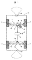
- FIG. 1 is a schematic configuration diagram of a vehicle 10 equipped with the steering control device 1 of the present embodiment.
- the vehicle 10 is a four-wheel steering (4WS) type vehicle that can steer both the front wheels 5 and the rear wheels 7.
- 4WS four-wheel steering
- the front wheels 5 and the rear wheels 7 are steered in the same direction.
- the front and rear wheels can be independently steered in opposite phases, and the minimum turning radius can be made smaller.
- the vehicle 10 includes a vehicle state sensor 2 for acquiring vehicle information such as vehicle speed information and shift lever information, a steering wheel 3 operated by a driver, a front wheel power steering device 4 for steering front wheels 5, and a rear wheel steering device 4.
- a rear wheel power steering device 6 that steers the wheels 7, an external world recognition sensor 8 that recognizes the external world of the vehicle 10 (a front recognition sensor 8f, a rear recognition sensor 8r), and a communication line (a part of which is illustrated) that connects them to each other. Is omitted).
- the steering control device 1 receives signals from the vehicle state sensor 2 and the external environment recognition sensor 8 via the communication line, and controls the front wheel power steering device 4 and the rear wheel power steering device 6 based on the received signals. Control.
- the steering control device 1 is actually a function of an ECU (Electronic Control Unit) including hardware such as a computing device such as a CPU, a main storage device, an auxiliary storage device, and a communication device. Then, while referring to the database recorded in the auxiliary storage device, the arithmetic unit executes the program loaded in the main storage device to realize each function of the parking determination unit 1a and the like described later. Description will be given while omitting such well-known techniques as appropriate.
- ECU Electronic Control Unit
- the front wheel power steering device 4 includes a steering sensor 3a (steering angle sensor, torque sensor, etc.) that detects a steering direction and a steering torque of the steering wheel 3 operated by a driver, and a front wheel rack shaft 4c connected to the front wheels 5 via a link. And a front wheel power steering motor 4b that applies a steering thrust to the front wheel rack shaft 4c, and a front wheel that applies a torque command to the front wheel power steering motor 4b based on a detection value of the steering sensor 3a (hereinafter referred to as "front wheel steering angle ⁇ f "). It comprises a steering angle control unit 4a.
- the front wheel power steering device 4 assists the steering of the front wheels 5 by causing the front wheel power steering motor 4b to generate steering thrust corresponding to the steering of the steering wheel 3 by the driver.
- the rear wheel power steering device 6 includes a rear wheel rack shaft 6c connected to the rear wheels 7 via a link, a rear wheel power steering motor 6b that applies steering thrust to the rear wheel rack shaft 6c, and a steering control device 1.
- the rear wheel steering angle control unit 6a provides a torque command to the rear wheel power steering motor 6b based on a command value (hereinafter, referred to as "rear wheel steering angle ⁇ r ").
- the rear wheel power steering device 6 causes the rear wheel power steering motor 6b to generate a steering thrust force corresponding to the command value from the steering control device 1, and steers the rear wheels 7.
- the relationship between the front wheel steering angle ⁇ f and the rear wheel steering angle ⁇ r will be described later.
- the external recognition sensor 8 processes image data captured by a stereo camera and recognizes obstacles and parking frames around the vehicle 10.
- the outside world recognition sensor 8 may be provided not only in the front and rear but also in the side of the vehicle for recognizing the side.
- the parking frame recognized by the outside world recognition sensor 8 is not limited to the area surrounded by the white line designated as the parking lot, and the vehicle 10 such as a vacant space between other vehicles or a vacant space surrounded by walls. It may be a parking area.
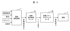
- a rear wheel steering angle control unit 6a and a rear wheel power steering motor 6b are mainly arranged between the steering control device 1 and the rear wheels 7.
- the vehicle information vehicle speed information, shift lever information
- the outside world recognition sensor 8 or the outside of the vehicle for example, a parking facility management system.
- Each information of the parking frame information of is input.
- the steering control device 1 calculates a predetermined rear wheel steering angle ⁇ r based on these input information, and gives the obtained rear wheel steering angle ⁇ r to the rear wheel steering angle control unit 6a.
- the rear wheel steering angle control unit 6a generates a torque command according to the difference between the input rear wheel steering angle ⁇ r and the actual rear wheel steering angle, and outputs the torque command to the rear wheel power steering motor 6b.
- the steering thrust is generated to change the direction of the rear wheels 7 to control the traveling direction of the vehicle 10.
- FIG. 3 is a functional block diagram showing details of the steering control device 1.
- the steering control device 1 includes a parking determination unit 1a, a vehicle/parking frame relationship determination unit 1b, and a gain control unit 1c.
- the parking determination unit 1a determines whether the driving mode of the vehicle 10 is the parking driving mode.
- the own vehicle/parking frame relationship determination unit 1b calculates the relationship between the vehicle 10 and the parking frame 9, and the gain control unit 1c is calculated by the own vehicle/parking frame relationship determination unit 1b.
- the rear wheel steering angle ⁇ r is determined based on the obtained information.
- ⁇ Parking determination unit 1a> As a method of determining the driving mode of the vehicle 10 by the parking determination unit 1a, there are a method of determining with a driver trigger and a method of determining based on vehicle information.
- the driver trigger method is a method of determining that the driving mode has been switched to the parking driving mode when the driver indicates to the vehicle 10 to start parking, such as when the driver presses the parking start button.
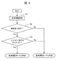
- the vehicle information method is a method of determining that the driving mode is switched to the parking driving mode based on the vehicle information (vehicle speed information, shift lever information) input from the vehicle state sensor 2. An example of this is shown in the flowchart of FIG.
- the parking determination unit 1a acquires vehicle information (vehicle speed information, shift lever information) necessary for determining the driving mode from the vehicle state sensor 2.
- the parking determination unit 1a determines whether the vehicle 10 is traveling at an extremely low speed (for example, 5 km/h or less) based on the acquired vehicle speed information.
- the processing is terminated after determining the normal operation mode, and when the vehicle is traveling at an extremely low speed, the processing proceeds to step S3.
- step S3 the parking determination unit 1a confirms the position of the shift lever based on the acquired shift lever information.
- a parking pattern such as parallel parking or reverse parking
- the vehicle 10 often repeats forward and reverse, and the shift lever enters "R" (Reverse, reverse) at least once. Based on such characteristics, the time shift of the shift lever position is observed, and when the shift lever does not enter "R" for a certain period of time, it is determined that the operation mode is the normal operation mode, and the processing is ended. On the other hand, if the shift lever enters "R" even once within a fixed time, it is determined that the operation mode is the parking operation mode, and the process ends.
- the flowchart in FIG. 4 is an example of a method of determining the driving mode using vehicle information, and determination may be performed using vehicle information other than vehicle speed information and shift lever information.
- vehicle information other than vehicle speed information and shift lever information.
- the time change of the front wheel steering angle, the accelerator pedal, the brake pedal, etc. may be used together when determining the driving mode.
- the driving mode may be estimated based on the surrounding situation detected by the outside world recognition sensor 8 or the map data (the vehicle 10 is in the parking area, etc.).
- ⁇ Own vehicle/parking frame relation determination unit 1b> Next, the relationship between the vehicle 10 and the parking frame 9 calculated by the own vehicle/parking frame relationship determination unit 1b will be described with reference to FIG. FIG.
- the lateral direction (lateral direction) of the parking frame 9 is x direction
- the longitudinal direction (front and rear direction) is y.
- the direction is.
- the own vehicle/parking frame relationship determination unit 1b grasps the position and shape of the parking frame 9 based on the parking frame information received from the outside world recognition sensor 8 or the outside of the vehicle.
- the parking frame 9 grasped by the own vehicle/parking frame relationship determination unit 1b is defined by its center coordinates 9C , an ideal posture angle ⁇ i during parking, an x-direction distance 9 x , and a y-direction distance 9 y .
- the relationship between the vehicle 10 and the parking frame 9 is the attitude angle difference ⁇ between the attitude angle ⁇ of the vehicle 10 and the ideal attitude angle ⁇ i , the x-direction distance ⁇ L x of the center coordinates 9 C of the vehicle 10 and the parking frame 9, and the vehicle 10 and the parking frame. It is expressed by the y-direction distance ⁇ L y of the center coordinate 9 C of the frame 9.
- the reference point of the vehicle 10 is the vehicle center point. Further, in FIG.
- the x-direction distance ⁇ L x and the y-direction distance ⁇ L y are represented by the relationship between the vehicle 10 and the center coordinates 9 C of the parking frame, but as a relationship with the points forming the parking frame 9. May be represented.
- ⁇ Gain controller 1c> After the relationship between the vehicle 10 and the parking frame 9 is calculated by the own vehicle/parking frame relationship determination unit 1b, the gain control unit 1c adjusts the gain of the rear wheel steering angle ⁇ r with respect to the front wheel steering angle ⁇ f . A gain adjusting method by the gain control unit 1c will be described with reference to FIGS.
- the gain control unit 1c positions the vehicle 10 in the rectangular area A 0 illustrated in FIG. 5, for example. If it is, the following gain adjustment control is started.
- the gain control unit 1c controls the gain of the rear wheel steering ⁇ r with respect to the front wheel steering angle ⁇ f to be constant.
- the minimum turning radius of the vehicle can be reduced, and the yaw motion is facilitated.
- the attitude angle of the vehicle changes significantly, and the attitude angle difference ⁇ greatly decreases.
- the attitude angle difference ⁇ is equal to or less than the threshold value (that is, when the attitude angle ⁇ of the vehicle 10 approaches the ideal attitude angle ⁇ i )
- the rear wheel steering with respect to the front wheel steering angle ⁇ f is changed according to the magnitude of the attitude angle difference ⁇ .
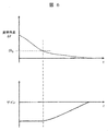
- Vary the gain of the angle ⁇ r Specifically, as shown in FIG. 6, the absolute value of the gain approaches 0 as the attitude angle difference ⁇ becomes smaller.
- the rear wheel steering angle ⁇ r is smaller than in the conventional control in which the gain is constant regardless of the attitude angle difference ⁇ , and the yaw motion of the vehicle 10 is less likely to occur.
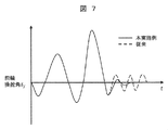
- the driver can easily change the attitude angle ⁇ of the vehicle 10 by a small amount, and as shown in FIG. 7, the correction steering angle of the driver near the parking frame is reduced and the steering frequency becomes a low frequency. The steering load on the driver can be reduced.
- the gain of the rear wheel steering angle ⁇ r with respect to the front wheel steering angle ⁇ f is adjusted according to the magnitude of the attitude angle difference ⁇ , but the x direction distance ⁇ L x and the y direction distance ⁇ L y are also taken into consideration.
- the gain may be adjusted by adjusting the gain. However, in this case, if the gain is set by giving priority to the attitude angle difference ⁇ over the x-direction distance ⁇ L x and the y-direction distance ⁇ L y , it is possible to realize steering more in line with the driver's feeling.
- FIG. 8 exemplifies a time transition of the x-direction distance ⁇ L x , the y-direction distance ⁇ L y , the attitude angle difference ⁇ , and the gain when the vehicle 10 is parked in the parking frame 9 shown in FIG.
- the driver operates the steering wheel 3 so as to gradually decrease the attitude angle difference ⁇ while reducing the x-direction distance ⁇ L x .
- the attitude angle ⁇ of the vehicle 10 is changed significantly while gradually reducing the x-direction distance ⁇ L x and the y-direction distance ⁇ L y .
- the attitude angle difference ⁇ is sharply reduced.
- the gain is constant and the value is the same as before.
- the driver makes the y-direction distance ⁇ L y closer to 0 while finely correcting the attitude angle difference ⁇ .
- the gain control unit 1c makes the gain of the rear-wheel steering angle ⁇ r relative to the front-wheel steering angle ⁇ f close to 0, which allows a slight change in the posture angle, thereby reducing the steering load on the driver's parking.
- the gain of the rear-wheel steering angle ⁇ r with respect to the front-wheel steering angle ⁇ f operated by the driver is controlled by the vehicle and the parking. Since the vehicle is gradually adjusted in accordance with the relative relationship between the frames, it is possible to finely steer the vehicle in the vicinity of the parking frame and reduce the steering load on the driver.
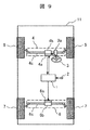
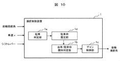
- the vehicle 10 according to the first embodiment includes the outside world recognition sensor 8 for recognizing the parking frame 9, but the vehicle 11 according to the present embodiment does not include the outside world recognition sensor 8 as illustrated in FIG. 9. Therefore, as shown in FIG. 10, unlike the first embodiment, the parking frame information is not input to the steering control device 1 of the present embodiment, but like the first embodiment, the front wheel steering angle information, the vehicle speed information, Each piece of shift lever information is input.
- the parking frame estimation unit 1d is added so that the same effect as that of the first embodiment can be obtained without inputting the parking frame information, and the parking frame estimated here is added.
- the rear wheel steering angle ⁇ r is decided based on the relative relationship between the vehicle and the vehicle.
- the operations of the parking determination unit 1a, the own vehicle/parking frame relation determination unit 1b, and the gain control unit 1c are the same as those in the first embodiment, and therefore, the description overlapping with the first embodiment will be omitted below.
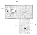
- the parking frame estimation unit 1d first predicts the vehicle 11 based on the front wheel steering angle ⁇ f , the steering angular velocity ⁇ , and the vehicle speed v, as illustrated in FIG. 11A. Estimate the path P 1 .
- the steering angular velocity ⁇ is a time derivative of the front wheel steering angle ⁇ f .
- the parking space estimation unit 1d is based on the predicted path P 1 that is estimated, estimates the parking space 9a.
- the estimated route end point P 1e is set as the center point of the parking frame 9a, and the total length 11 L and the total width 11 W of the vehicle 11 plus a margin is set as a distance from the parking frame center point (estimated route end point P 1e ).
- the parking frame 9a can be estimated by adding and subtracting. If it is difficult to estimate the y-direction distance 9 y of the parking frame 9 a from the vehicle speed v, the estimation need not be performed.
- the estimation accuracy by the parking frame estimation unit 1d improves, so that the margin amount added to the total length 11 L or the total width 11 W of the vehicle 11 is small. It may be a value.
- the parking frame 9b estimated at the end of parking becomes smaller than the parking frame 9a estimated at the start of parking, and it is considered that the parking frame 9b is closer to the actual parking frame 9.
- the gain of the rear-wheel steering angle ⁇ r with respect to the front-wheel steering angle ⁇ f operated by the driver is as follows even in the vehicle without the external environment recognition sensor 8. Since the vehicle is gradually adjusted according to the relative relationship between the own vehicle and the parking frame, it is possible to finely steer the own vehicle in the vicinity of the parking frame and reduce the steering load on the driver.
- the own vehicle/parking frame relation determination unit 1b performs calculation based on the parking frame or the like recognized by the external recognition sensor 8, and in the second embodiment, based on the parking frame estimated by the parking frame estimation unit 1d, although an appropriate gain value was set in the gain control unit 1c based on the calculation result, in the present embodiment, the gain control is performed without using the parking frame information from the external world recognition sensor 8 or the parking frame estimation unit 1d.
- the unit 1c sets an appropriate gain.
- the parking determination unit 1a detects the shift to the parking operation mode, the gain control portion 1c, the vehicle speed v, the front wheel steering angle [delta] f, on the basis of the time change data of the steering angular velocity omega, for front-wheel steering angle [delta] f
- the gain of the rear wheel steering angle ⁇ r is adjusted. This detailed procedure will be described with reference to FIGS. 13 and 14.
- Fig. 13 shows an example of the parking pattern of the driver.
- the posture of the vehicle 11 changes at the same time as the vehicle speed v is increased after the vehicle is stopped. Then, the operation of the handle 3 is started.
- An example of the driver performing this operation is in the area A 1 in FIG. 14 away from the area where the driver is trying to park.
- the driver steers the steering wheel 3 largely and starts decelerating in order to secure the yaw motion of the vehicle 11.
- the steering angular velocity ⁇ has a positive value.
- An example of the driver performing this operation is in the area A 2 in FIG.
- the steering wheel 3 is turned back while maintaining the vehicle speed v so that the posture angle ⁇ of the vehicle 11 converges to the ideal posture angle ⁇ i. Is done.
- An example of the driver performing this steering is in the area A 3 of FIG. In this region, when it is determined that the vehicle attitude angle is not significantly changed by comparing the vehicle speed v, the front wheel steering angle ⁇ f , the steering angular velocity ⁇ with time, and the positive/negative of the steering angle and the steering angular velocity ⁇ , Gradually reduce the gain of the rear wheels from the initial value.
- the driver approaches the vehicle speed v to 0 while performing a slight steering in order to finely correct the attitude angle ⁇ of the vehicle 11.
- This minute steering does not always have to be performed in one direction, and may be continuously performed in both directions as shown in FIG.
- An example of the driver performing this steering is in the area A 4 in FIG.
- the absolute value of the gain of the rear wheel steering angle ⁇ r with respect to the front wheel steering angle ⁇ f is brought close to 0 from the time transition of the vehicle speed v, the front wheel steering angle, and the steering angular velocity ⁇ .
- the control is similar to that of two-wheel steering, and the attitude angle of the vehicle is less likely to change, and the steering load on the driver is reduced.
- the gain of the rear wheel steering angle ⁇ r with respect to the front wheel steering angle ⁇ f operated by the driver is Since the vehicle is gradually adjusted according to the behavior of the vehicle, it is possible to finely steer the own vehicle and reduce the steering load on the driver.
- the present invention is not limited to the above-mentioned embodiments, but includes various modifications.
- the above-described embodiments have been described in detail for the purpose of explaining the present invention in an easy-to-understand manner, and are not necessarily limited to having all the configurations.
- SYMBOLS 1... Steering control device, 1a... Parking determination part, 1b... Own vehicle/parking frame relation determination part, 1c... Gain control part, 1d... Parking frame estimation part, 2... Vehicle state sensor, 3... Steering wheel, 3a... Steering sensor 4... Front wheel power steering device, 4a... Front wheel steering angle control unit 4b... Front wheel power steering motor, 4c... Front wheel rack shaft, 5... Front wheel, 6... Rear wheel power steering device, 6a... Rear wheel steering angle control unit, 6b ... rear wheel power steering motor, 6c... rear wheel rack shaft, 7... rear wheel, 8... external recognition sensor, 8f... front recognition sensor, 8r... rear recognition sensor, 9, 9a, 9b, 9c... parking frame 10, 11... Vehicle
Landscapes
- Engineering & Computer Science (AREA)
- Chemical & Material Sciences (AREA)
- Combustion & Propulsion (AREA)
- Transportation (AREA)
- Mechanical Engineering (AREA)
- Physics & Mathematics (AREA)
- Mathematical Physics (AREA)
- Steering Control In Accordance With Driving Conditions (AREA)
- Control Of Driving Devices And Active Controlling Of Vehicle (AREA)
- Steering-Linkage Mechanisms And Four-Wheel Steering (AREA)
Abstract
本発明は、四輪操舵車両の駐車時に、ドライバが操作する前輪操舵角δfに対する後輪操舵δrのゲインを、自車と駐車枠の相対的な関係に応じて徐々に調整し、駐車枠近傍での自車の微細な操舵を可能とすることで、ドライバの操舵負荷を低減させることができる操舵制御装置を提供することを目的とする。このため、ドライバの操作による前輪操舵角に基づいて、後輪操舵システムによる後輪操舵角を制御する車両の操舵制御装置であって、自車が駐車運転モードに移行したときに、自車と駐車枠の位置関係が近づくほど、前記前輪操舵角に対する前記後輪操舵角のゲインの絶対値を小さくする演算装置を備えた。
Description
本発明は、車両の前輪の操舵に応じて後輪を操舵制御する、操舵制御装置に関する。
4輪車等においては、前輪のみならず後輪も操舵できる四輪操舵式の車両が知られている。
例えば、特許文献1の要約書には、「操舵制御装置10のECU40は自車両100の左前輪21~右後輪24の操舵角を制御する。ECU40は、自車両100が駐車枠Pに平行ではないときは、左前輪21、右前輪22と左後輪23、右後輪24との操舵方向が異なる方向である逆相となるように制御する。逆相とすることにより自車両100の方向を変更しやすくなり、自車両100を駐車枠Pに平行にすることが容易となる。また、ECU40は、自車両100が駐車枠Pに平行であるときは、左前輪21、右前輪22と左後輪23、右後輪24との操舵方向が同じ方向である同相となるように制御する。同相とすることにより自車両100の方向を維持しつつ平行に移動させ、自車両100と駐車枠Pとの左右の間隙を調整することが容易となる。」と記載されている。
しかしながら、特許文献1では、自車が駐車枠に対して平行にならない限り、前輪に対する後輪の操舵制御が逆相制御から同相制御に変更されないので、自車が駐車枠に対して平行になるまでの期間は、車両の姿勢の微修正が行いづらいという問題があった。また、後輪の操舵方向が前輪の逆相から同相に急に切り替わると、操舵時の車両の挙動が急変するので、ドライバに違和感を与えるという問題もあった。
そこで、本発明は、四輪操舵車両の駐車時に、ドライバが操作する前輪操舵角に対する後輪操舵のゲインを、自車と駐車枠の相対的な関係に応じて徐々に調整し、駐車枠近傍での自車の微細な操舵を可能とすることで、ドライバの操舵負荷を低減させることができる操舵制御装置を提供することを目的とする。
上記課題を解決するため、本発明の車両の操舵制御装置は、ドライバの操作による前輪操舵角に基づいて、後輪操舵システムによる後輪操舵角を制御するものであって、自車が駐車運転モードに移行したときに、自車と駐車枠の位置関係が近づくほど、前記前輪操舵角に対する前記後輪操舵角のゲインの絶対値を小さくする演算装置を備えたものとした。
本発明の操舵制御装置によれば、四輪操舵車両の駐車時に、ドライバが操作する前輪操舵角に対する後輪操舵のゲインが、自車と駐車枠の相対的な関係に応じて徐々に調整されるため、駐車枠近傍での自車の微細な操舵が可能となり、ドライバの操舵負荷を低減させることができる。
以下、本発明の実施例に係る操舵制御装置について図面を用いて説明する。
図1から図8を用いて、本発明の実施例1に係る操舵制御装置1を説明する。
図1は、本実施例の操舵制御装置1を搭載した車両10の概略構成図である。この車両10は、前輪5と後輪7の双方を操舵可能な4輪操舵(4WS)式の車両であり、通常速度での走行時には、前輪5と後輪7は同じ方向に操舵されるが、低速走行時には前後輪を独立して逆相に操舵でき、最小回転半径をより小さくすることができる。
車両10には、操舵制御装置1の他に、車速情報やシフトレバー情報などの車両情報を取得する車両状態センサ2、ドライバが操作するハンドル3、前輪5を操舵する前輪パワーステアリング装置4、後輪7を操舵する後輪パワーステアリング装置6、車両10の外界を認識する外界認識センサ8(前方認識センサ8f、後方認識センサ8r)、および、それらを相互に接続する通信ライン(一部は図示を省略)を備えている。そして、操舵制御装置1は、通信ラインを介して、車両状態センサ2や外界認識センサ8からの信号を受信し、受信した信号に基づいて、前輪パワーステアリング装置4や後輪パワーステアリング装置6を制御する。なお、操舵制御装置1は、実際には、CPU等の演算装置、主記憶装置、補助記憶装置、および、通信装置などのハードウェアを備えたECU(Electronic Control Unit)の一機能である。そして、補助記憶装置に記録されたデータベースを参照しながら、主記憶装置にロードされたプログラムを演算装置が実行することで、後述する駐車判定部1a等の各機能を実現するが、以下では、このような周知技術を適宜省略しながら説明する。
前輪パワーステアリング装置4は、ドライバの操作によるハンドル3の操舵方向や操舵トルクを検出する操舵センサ3a(操舵角センサ、トルクセンサ等)と、リンクを介して前輪5と接続される前輪ラック軸4cと、前輪ラック軸4cに操舵推力を与える前輪パワーステアリングモータ4bと、操舵センサ3aの検出値(以下、「前輪操舵角δf」と称する)に基づき前輪パワーステアリングモータ4bにトルク指令を与える前輪操舵角制御ユニット4aからなる。これにより、前輪パワーステアリング装置4は、ドライバによるハンドル3の操舵に応じた操舵推力を前輪パワーステアリングモータ4bで発生させ、前輪5の操舵をアシストする。
後輪パワーステアリング装置6は、リンクを介して後輪7と接続される後輪ラック軸6cと、後輪ラック軸6cに操舵推力を与える後輪パワーステアリングモータ6bと、操舵制御装置1からの指令値(以下、「後輪操舵角δr」と称する)に基づき後輪パワーステ
アリングモータ6bにトルク指令を与える後輪操舵角制御ユニット6aからなる。これにより、後輪パワーステアリング装置6は、操舵制御装置1からの指令値に応じた操舵推力を後輪パワーステアリングモータ6bで発生させ、後輪7を操舵する。なお、前輪操舵角δfと後輪操舵角δrの関係は後述する。
アリングモータ6bにトルク指令を与える後輪操舵角制御ユニット6aからなる。これにより、後輪パワーステアリング装置6は、操舵制御装置1からの指令値に応じた操舵推力を後輪パワーステアリングモータ6bで発生させ、後輪7を操舵する。なお、前輪操舵角δfと後輪操舵角δrの関係は後述する。
更に、外界認識センサ8(前方認識センサ8f、後方認識センサ8r)は、ステレオカメラで撮影した画像データなどを処理して車両10の周囲の障害物や駐車枠などを認識する。なお、外界認識センサ8は、前方、後方のみならず、側方を認識するためのものを車両側方に備えてもよい。また、外界認識センサ8が認識する駐車枠とは、駐車場として指定された白線に囲まれ領域のみならず、他車両の間の空きスペースや、壁に囲まれた空きスペースなど、車両10が駐車可能な領域であってもよい。
次に、図2~図8を用い、操舵制御装置1による後輪7の操舵制御の詳細を説明する。
図2の後輪操舵システムの概略図に示すように、操舵制御装置1と後輪7の間には、主に、後輪操舵角制御ユニット6aと後輪パワーステアリングモータ6bが配置される。操舵制御装置1には、操舵センサ3aからの前輪操舵角情報、車両状態センサ2からの車両情報(車速情報、シフトレバー情報)、外界認識センサ8または車外(例えば、駐車施設の管理システム)からの駐車枠情報の各情報が入力される。そして、操舵制御装置1は、これらの入力情報に基づき所定の後輪操舵角δrを演算し、求めた後輪操舵角δrを後輪操舵角制御ユニット6aに与える。後輪操舵角制御ユニット6aでは、入力された後輪操舵角δrと実際の後輪操舵角の差などに応じたトルク指令を生成し、これを後輪パワーステアリングモータ6bに与えることで所望の操舵推力を発生させて後輪7の向きを変化させ、車両10の進行方向を制御する。
図3は、操舵制御装置1の詳細を示す機能ブロック図である。ここに示すように、操舵制御装置1は、駐車判定部1a、自車/駐車枠関係判定部1b、ゲイン制御部1cを備えている。まず、駐車判定部1aでは、車両10の運転モードが、駐車運転モードか否かを判断する。そして、駐車モードと判断された場合、自車/駐車枠関係判定部1bは、車両10と駐車枠9の関係を演算し、ゲイン制御部1cは、自車/駐車枠関係判定部1bで演算された情報を基に後輪操舵角δrを決定する。以下、図4から図8を用いて、操舵制御装置1の各部での詳細処理を説明する。
<駐車判定部1a>
駐車判定部1aが車両10の運転モードを判定する方法としては、ドライバトリガで判定する方法と、車両情報を基に判定する方法がある。ドライバトリガによる方法は、ドライバが駐車開始ボタンを押した場合など、ドライバが車両10に駐車開始の意思を示したときに、運転モードが駐車運転モードに切り替わったと判定する方法である。
<駐車判定部1a>
駐車判定部1aが車両10の運転モードを判定する方法としては、ドライバトリガで判定する方法と、車両情報を基に判定する方法がある。ドライバトリガによる方法は、ドライバが駐車開始ボタンを押した場合など、ドライバが車両10に駐車開始の意思を示したときに、運転モードが駐車運転モードに切り替わったと判定する方法である。
一方、車両情報による方法は、車両状態センサ2から入力された車両情報(車速情報、シフトレバー情報)を基に、運転モードが駐車運転モードに切り替わったと判定する方法である。この一例を、図4のフローチャートに示す。
まず、処理S1では、駐車判定部1aは、運転モードの判定に必要な車両情報(車速情報、シフトレバー情報)を、車両状態センサ2から取得する。
次に、処理S2では、駐車判定部1aは、取得した車速情報に基づいて車両10が極低速(例えば5km/h以下など)で走行しているか判定する。極低速で走行していない場合は通常運転モードと判定してから処理を終え、極低速で走行している場合は処理S3に進む。
次に、処理S3では、駐車判定部1aは、取得したシフトレバー情報に基づいてシフトレバーの位置を確認する。縦列駐車や後退駐車など駐車パターンでは、車両10は前進と後退を繰り返すことが多く、少なくとも1回はシフトレバーが「R」(Reverse、後退)に入る。このような特性を踏まえ、シフトレバー位置の時間推移を観察し、一定時間以上シフトレバーが「R」に入らなかった場合は、運転モードが通常運転モードであると判定し処理を終える。一方、シフトレバーが一定時間内に一回でも「R」に入った場合は、運転モードが駐車運転モードであると判定し処理を終える。
なお、図4のフローチャートは車両情報を用いた運転モードの判定方法の一例であり、車速情報やシフトレバー情報以外の車両情報を用いて判定してもよい。例えば、運転モードを判定する際に、前輪操舵角、アクセルペダル、ブレーキペダルなどの時刻変化を併用してもよい。また、外界認識センサ8が検出した周辺状況や、地図データ(車両10がパーキングエリアにいるなど)に基づいて、運転モードを推定してもよい。
<自車/駐車枠関係判定部1b>
次に、自車/駐車枠関係判定部1bで演算される、車両10と駐車枠9の関係について、図5を用いながら説明する。図5は、車両10が点線で示す長方形の駐車枠9に駐車する途中の様子を示す図であり、駐車枠9の短手方向(横方向)をx方向、長手方向(前後方向)をy方向としている。まず、自車/駐車枠関係判定部1bは、駐車枠9の位置や形状を、外界認識センサ8または車外から受信した駐車枠情報に基づき把握する。自車/駐車枠関係判定部1bが把握する駐車枠9は、その中心座標9C、駐車時の理想姿勢角θi、x方向距離9x、y方向距離9yで定義される。車両10と駐車枠9の関係は、車両10の姿勢角θと理想姿勢角θiの姿勢角差Δθ、車両10と駐車枠9の中心座標9Cのx方向距離ΔLx、車両10と駐車枠9の中心座標9Cのy方向距離ΔLyで表現される。なお、車両10と駐車枠9の姿勢角差Δθ及び距離を規定する際、車両10の基準点は車両中心点とする。また、図5では、x方向距離ΔLxとy方向距離ΔLyを車両10と駐車枠の中心座標9Cとの関係で表しているが、駐車枠9を構成している点との関係として表してもよい。
<ゲイン制御部1c>
自車/駐車枠関係判定部1bにより車両10と駐車枠9の関係が演算された後、ゲイン制御部1cにより前輪操舵角δfに対する後輪操舵角δrのゲインが調整される。図5~図8を用いながら、ゲイン制御部1cによるゲイン調整方法を説明する。
ゲイン制御部1cは、車両10と駐車枠9のx方向距離ΔLxまたはy方向距離ΔLyが閾値以内となったとき、例えば、図5に図示する矩形の領域A0に車両10が位置している場合に、以下のゲイン調整制御を開始する。
図6のグラフに示すように、姿勢角差Δθが所定の閾値th0以上である場合、ゲイン制御部1cは、前輪操舵角δfに対する後輪操舵δrのゲインを一定に制御する。この場合、従来通り後輪7を前輪5と逆方向に操舵(逆相)することで、車両の最小回転半径を小さくすることができ、ヨー運動が容易になる。これにより、車両の姿勢角が大きく変化し、姿勢角差Δθが大きく減少する。
一方、姿勢角差Δθが閾値以下になると(すなわち、車両10の姿勢角θが理想姿勢角θiに近づくと)、姿勢角差Δθの大きさに応じて前輪操舵角δfに対する後輪操舵角δrのゲインを変動させる。具体的には、図6に示すように、姿勢角差Δθが小さくなればなるほど、ゲインの絶対値を0に近づける。
これにより、姿勢角差Δθに拘わらずゲインが一定である従来制御と比較して、後輪操舵角δrは小さいものとなり、車両10のヨー運動が発生しにくくなる。この結果、ドライバが車両10の姿勢角θを微小量変化させることが容易となり、図7に示すとおり駐車枠付近におけるドライバの修正操舵角の低減及び操舵周波数が低周波になることで、駐車に対するドライバの操舵負荷を低減できる。
なお、図6では、姿勢角差Δθの大きさに応じて、前輪操舵角δfに対する後輪操舵角δrのゲインを調整したが、x方向距離ΔLx、y方向距離ΔLyも考慮してゲインを調整してもよい。ただし、この場合、x方向距離ΔLxやy方向距離ΔLyよりも、姿勢角差Δθを優先してゲインを設定すれば、よりドライバの感覚に沿った操舵を実現することができる。
図8は、図5に示す駐車枠9に車両10を駐車する際の、x方向距離ΔLx、y方向距離ΔLy、姿勢角差Δθ、ゲインの時間推移を例示したものである。
まず、第一期間(x方向距離ΔLxがth1より大きい期間)では、ドライバはx方向距離ΔLxを減らしつつ姿勢角差Δθを少しずつ減少させるようにハンドル3を操作する。
次に、第二期間(姿勢角差Δθがth2より大きい期間)では、x方向距離ΔLx及びy方向距離ΔLyを少しずつ減らしながら、車両10の姿勢角θを大きく変化させることで、姿勢角差Δθを急激に減少させる。
第一期間と第二期間においては、ゲインを一定とし従来通りの値とする。
最後に、第三期間(姿勢角差Δθがth2より小さい期間)では、ドライバは姿勢角差Δθを微修正しながら、y方向距離ΔLyを0に近づける。この期間では、ゲイン制御部1cで前輪操舵角δfに対する後輪操舵角δrのゲインを0に近づけることにより微小な姿勢角変化が可能となり、ドライバの駐車に対する操舵負荷を低減できる。
以上で説明したように、本実施例の操舵制御装置によれば、四輪操舵車両の駐車時に、ドライバが操作する前輪操舵角δfに対する後輪操舵角δrのゲインが、自車と駐車枠の相対的な関係に応じて徐々に調整されるため、駐車枠近傍での自車の微細な操舵が可能となり、ドライバの操舵負荷を低減させることができる。
次に、図9~図11Bを用いて、本発明の実施例2の操舵制御装置1を説明する。なお、実施例1との共通点は重複説明を省略する。
実施例1の車両10は、駐車枠9を認識するために外界認識センサ8を備えていたが、本実施例の車両11は、図9に示すように、外界認識センサ8を備えていない。このため、図10に示すように、本実施例の操舵制御装置1には、実施例1と異なり、駐車枠情報は入力されないが、実施例1と同様に、前輪操舵角情報、車速情報、シフトレバー情報の各情報は入力される。
そこで、本実施例の操舵制御装置1では、駐車枠情報の入力がなくとも実施例1と同様の効果を得ることができるように、駐車枠推定部1dを追加し、ここで推定した駐車枠と自車の相対関係を基に、後輪操舵角δrを決定することとした。なお、駐車判定部1a、自車/駐車枠関係判定部1b、ゲイン制御部1cの作用は実施例1と同等であるので、以下では、実施例1と重複する説明は省略する。
図11A、図11Bを用いながら、本実施例の駐車枠推定部1dの動作を説明する。
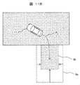
駐車判定部1aが駐車運転モードへの移行を検知すると、駐車枠推定部1dは、まず、図11Aに示すとおり、前輪操舵角δf、操舵角速度ω、車速vに基づいて、車両11の予測経路P1を推定する。ここで操舵角速度ωは前輪操舵角δfを時間微分したものである。次に、駐車枠推定部1dは、推定された予測経路P1を基準に、駐車枠9aを推定する。一例として、推定経路終端点P1eを駐車枠9aの中心点とし、車両11の全長11L、全幅11Wにマージンを加えたものを駐車枠中心点(推定経路終端点P1e)から距離を足し引きすることで駐車枠9aを推定できる。なお、車速vより駐車枠9aのy方向距離9yの推定が困難な場合は推定を行わなくてもよい。
車両11が推定した駐車枠9aに近づき更に減速すると、図11Bに示すように、駐車枠推定部1dによる推定精度が向上するため、車両11の全長11Lや全幅11Wに加えるマージン量を小さな値としてもよい。これにより駐車開始時に推定した駐車枠9aより、駐車終期に推定した駐車枠9bの方が小さくなり、駐車枠9bの方が実際の駐車枠9に近いと考えられる。
以上で説明したように、本実施例の操舵制御装置によれば、外界認識センサ8を有さない車両においても、ドライバが操作する前輪操舵角δfに対する後輪操舵角δrのゲインが、自車と駐車枠の相対的な関係に応じて徐々に調整されるため、駐車枠近傍での自車の微細な操舵が可能となり、ドライバの操舵負荷を低減させることができる。
次に、図12~図14を用いて、本発明の実施例3の操舵制御装置1を説明する。なお、実施例2との共通点は重複説明を省略する。
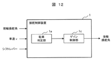
実施例1では外界認識センサ8が認識した駐車枠等を基に、実施例2では駐車枠推定部1dが推定した駐車枠を基に、自車/駐車枠関係判定部1bが演算を行い、その演算結果に基づいて、ゲイン制御部1cで適切なゲイン値を設定していたが、本実施例では、外界認識センサ8や駐車枠推定部1dからの駐車枠情報を用いずに、ゲイン制御部1cで適切なゲインを設定する。
このため、駐車判定部1aが駐車運転モードへの移行を検知すると、ゲイン制御部1cは、車速v、前輪操舵角δf、操舵角速度ωの時間推移情報に基づいて、前輪操舵角δfに対する後輪操舵角δrのゲインを調整する。この詳細な手順に関して図13及び図14を用いて説明する。
図13にドライバの駐車パターンの一例を示す。
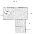
第一期間(駐車運転モード中の最高速度との関係で定まる閾値th3以下に車速vが減速するまでの期間)においては、停車時から車速vを上げていくと同時に車両11の姿勢が変わるようにハンドル3の操作を開始する。ドライバがこの操作を行う一例として、ドライバが駐車しようとしている領域から離れた図14の領域A1内が挙げられる。
第二期間(車速vが減速を始めてから操舵角速度ωがゼロクロスするまでの期間)においては、車両11のヨー運動を確保するため、ドライバはハンドル3を大きく操舵するとともに減速を行い始める。この際、図13に示す通り、操舵角速度ωは正の値をとっている。ドライバがこの操作を行う一例として図14の領域A2内が挙げられる。
なお、車速v、前輪操舵角δf、操舵角速度ωの時間推移より車両が大きく姿勢を変化している際中であると判断されたとき、すなわち、図13の第一期間と第二期間に相当すると判断されたときには、まだ車両11の操舵の微小修正は不要な期間と考えられるので、前輪操舵角δfに対する後輪操舵角δrのゲインは、通常走行時と同様に一定とする。
第三期間(操舵角速度ωがゼロクロスしてから再度ゼロクロスするまでの期間)においては、車両11の姿勢角θが理想姿勢角θiに収束するよう、車速vを保ちながらハンドル3の切り戻し動作が行われる。ドライバがこの操舵を行う一例として図14の領域A3内が挙げられる。この領域内では、車速v、前輪操舵角δf、操舵角速度ωの時間推移及び操舵角と操舵角速度ωの正負を比較することで車両の姿勢角を大きく変化させないと判断された場合、前輪に対する後輪のゲインを最初の値より少しずつ下げていく。
第四期間(操舵角速度ωが再度ゼロクロスした以降の期間)においては、車両11の姿勢角θを微修正するためドライバは微小な操舵を行いながら、車速vを0に近づけていく。この微小な操舵は必ずしも一方向に操舵を行うわけではなく、図13に示す通り連続的に双方向に行う場合もある。ドライバがこの操舵を行う一例として、図14の領域A4内が挙げられる。この領域内では、車速v、前輪操舵角、操舵角速度ωの時間推移より、前輪操舵角δfに対する後輪操舵角δrのゲインの絶対値を0に近づける。これより、駐車終期においては2輪操舵に近い制御になり、車両の姿勢角が変化しにくくなりドライバの操舵負荷が低減する。
以上で説明したように、本実施例の操舵制御装置によれば、駐車枠情報を用いない場合であっても、ドライバが操作する前輪操舵角δfに対する後輪操舵角δrのゲインが、車両の挙動に応じて徐々に調整されるため、自車の微細な操舵が可能となり、ドライバの操舵負荷を低減させることができる。
なお、本発明は上記した各実施例に限定されるものではなく、様々な変形例が含まれる。例えば、上記した実施例は本発明を分かりやすく説明するために詳細に説明したものであり、必ずしも全ての構成を備えるに限定させるものではない。
1…操舵制御装置、1a…駐車判定部、1b…自車/駐車枠関係判定部、1c…ゲイン制御部、1d…駐車枠推定部、2…車両状態センサ、3…ハンドル、3a…操舵センサ、4…前輪パワーステアリング装置、4a…前輪操舵角制御ユニット4b…前輪パワーステアリングモータ、4c…前輪ラック軸、5…前輪、6…後輪パワーステアリング装置、6a…後輪操舵角制御ユニット、6b…後輪パワーステアリングモータ、6c…後輪ラック軸、7…後輪、8…外界認識センサ、8f…前方認識センサ、8r…後方認識センサ、9、9a、9b、9c…駐車枠、10、11…車両
Claims (12)
- ドライバの操作による前輪操舵角に基づいて後輪操舵システムによる後輪操舵角を制御する、車両の操舵制御装置であって、
自車が駐車運転モードに移行したときに、自車と駐車枠の位置関係が近づくほど、前記前輪操舵角に対する前記後輪操舵角のゲインの絶対値を小さくする演算装置を備えたことを特徴とする操舵制御装置。 - 請求項1に記載の操舵制御装置において、
前記ゲインは0以下の値であることを特徴とする操舵制御装置。 - 請求項1に記載の操舵制御装置において、
前記位置関係は、自車と駐車枠との姿勢角差を含むことを特徴とする操舵制御装置。 - 請求項3に記載の操舵制御装置において、
前記位置関係は、自車と駐車枠との前後方向距離または横方向距離を含むことを特徴とする操舵制御装置。 - 請求項4に記載の操舵制御装置において、
前記前後方向距離または前記横方向距離よりも、前記姿勢角差を優先して、前記ゲインの絶対値を設定することを特徴とする操舵制御装置。 - 請求項1に記載の操舵制御装置において、
前記駐車枠は、前記車両の外界を認識する外界認識センサからの情報に基づき認識されたものであることを特徴とする操舵制御装置。 - 請求項1に記載の操舵制御装置において、
前記駐車枠は、前記前輪操舵角または操舵角速度、及び、車速の時間推移情報に基づき推定されたものであることを特徴とする操舵制御装置。 - 請求項1に記載の操舵制御装置において、
前記駐車枠は、車外から受信した駐車枠情報に基づき認識されたものであることを特徴とする操舵制御装置。 - ドライバの操作による前輪操舵角に基づいて後輪操舵システムによる後輪操舵角を制御する、車両の操舵制御装置であって、
自車が駐車運転モードに移行したときに、前記前輪操舵角または操舵角速度の時間推移情報に基づいて、前記前輪操舵角に対する後輪操舵角のゲインの絶対値を小さくすることを特徴とする操舵制御装置。 - 請求項9に記載の操舵制御装置において、
車速の時間推移情報に基づいて、前記前輪操舵角に対する後輪操舵角のゲインの絶対値を小さくすることを特徴とする操舵制御装置。 - 請求項10に記載の操舵制御装置において、
車速が極低速かつ切り戻し動作の修正操舵区間の操舵角と操舵角速度に基づいて、前記前輪操舵角に対する後輪操舵角のゲインの絶対値を小さくすることを特徴とする操舵制御装置。 - ドライバの操作による前輪操舵角に基づいて後輪操舵システムによる後輪操舵角を制御する、車両の操舵制御方法であって、
自車が駐車運転モードに移行したときに、自車と駐車枠の位置関係が近づくほど、前記前輪操舵角に対する前記後輪操舵角のゲインの絶対値を小さくすることを特徴とする操舵制御方法。
Priority Applications (3)
| Application Number | Priority Date | Filing Date | Title |
|---|---|---|---|
| CN201980085432.8A CN113260553B (zh) | 2019-01-28 | 2019-08-22 | 转向控制装置和转向控制方法 |
| DE112019006007.4T DE112019006007B4 (de) | 2019-01-28 | 2019-08-22 | Lenksteuervorrichtung und -verfahren |
| US17/416,126 US11975775B2 (en) | 2019-01-28 | 2019-08-22 | Steering control device and steering control method |
Applications Claiming Priority (2)
| Application Number | Priority Date | Filing Date | Title |
|---|---|---|---|
| JP2019012085A JP7203617B2 (ja) | 2019-01-28 | 2019-01-28 | 操舵制御装置、および、操舵制御方法 |
| JP2019-012085 | 2019-01-28 |
Publications (1)
| Publication Number | Publication Date |
|---|---|
| WO2020158021A1 true WO2020158021A1 (ja) | 2020-08-06 |
Family
ID=71840530
Family Applications (1)
| Application Number | Title | Priority Date | Filing Date |
|---|---|---|---|
| PCT/JP2019/032825 Ceased WO2020158021A1 (ja) | 2019-01-28 | 2019-08-22 | 操舵制御装置、および、操舵制御方法 |
Country Status (5)
| Country | Link |
|---|---|
| US (1) | US11975775B2 (ja) |
| JP (1) | JP7203617B2 (ja) |
| CN (1) | CN113260553B (ja) |
| DE (1) | DE112019006007B4 (ja) |
| WO (1) | WO2020158021A1 (ja) |
Families Citing this family (6)
| Publication number | Priority date | Publication date | Assignee | Title |
|---|---|---|---|---|
| KR102986773B1 (ko) * | 2021-06-28 | 2026-07-03 | 현대자동차주식회사 | 자동차용 후륜 조향 제어 시스템 및 방법 |
| US12583514B2 (en) * | 2021-08-23 | 2026-03-24 | Hyundai Mobis Co., Ltd. | Four-wheel steering control device and method |
| CN114312998B (zh) * | 2022-01-14 | 2023-03-28 | 中国第一汽车股份有限公司 | 后轮转向控制方法、装置、控制单元、车辆及存储介质 |
| KR102662632B1 (ko) * | 2022-01-14 | 2024-05-03 | 현대모비스 주식회사 | 4륜 독립 조향 장치 및 그 제어 방법 |
| US12296905B2 (en) | 2022-10-27 | 2025-05-13 | Trimble Inc. | Techniques for controlling autonomous 4WS vehicles |
| CN120462376A (zh) * | 2024-07-16 | 2025-08-12 | 比亚迪股份有限公司 | 泊车控制方法、设备、存储介质以及一种车辆 |
Citations (4)
| Publication number | Priority date | Publication date | Assignee | Title |
|---|---|---|---|---|
| JPS61163063A (ja) * | 1985-01-11 | 1986-07-23 | Fuji Heavy Ind Ltd | 自動車の前後輪操舵装置 |
| JPH0891238A (ja) * | 1994-09-28 | 1996-04-09 | Fuji Heavy Ind Ltd | 後輪操舵装置の制御方法 |
| JPH08287398A (ja) * | 1995-04-18 | 1996-11-01 | Toyota Motor Corp | 車両誘導装置 |
| JP2011225019A (ja) * | 2010-04-15 | 2011-11-10 | Toyota Motor Corp | 操舵制御装置 |
Family Cites Families (8)
| Publication number | Priority date | Publication date | Assignee | Title |
|---|---|---|---|---|
| JP3899739B2 (ja) * | 1999-09-21 | 2007-03-28 | 日産自動車株式会社 | 車両用操舵装置 |
| US9586471B2 (en) | 2013-04-26 | 2017-03-07 | Carla R. Gillett | Robotic omniwheel |
| US8430192B2 (en) | 2010-01-04 | 2013-04-30 | Carla R. Gillett | Robotic omniwheel vehicle |
| JP6388187B2 (ja) * | 2016-07-28 | 2018-09-12 | 日本精工株式会社 | 電動パワーステアリング装置 |
| RU2730808C1 (ru) * | 2017-06-23 | 2020-08-26 | Ниссан Мотор Ко., Лтд. | Способ управления парковкой и устройство управления парковкой |
| US10960820B2 (en) * | 2017-08-03 | 2021-03-30 | Mitsubishi Electric Corporation | Vehicle periphery image display device and vehicle periphery image display method |
| US12583514B2 (en) * | 2021-08-23 | 2026-03-24 | Hyundai Mobis Co., Ltd. | Four-wheel steering control device and method |
| KR102662632B1 (ko) * | 2022-01-14 | 2024-05-03 | 현대모비스 주식회사 | 4륜 독립 조향 장치 및 그 제어 방법 |
-
2019
- 2019-01-28 JP JP2019012085A patent/JP7203617B2/ja active Active
- 2019-08-22 WO PCT/JP2019/032825 patent/WO2020158021A1/ja not_active Ceased
- 2019-08-22 DE DE112019006007.4T patent/DE112019006007B4/de active Active
- 2019-08-22 CN CN201980085432.8A patent/CN113260553B/zh active Active
- 2019-08-22 US US17/416,126 patent/US11975775B2/en active Active
Patent Citations (4)
| Publication number | Priority date | Publication date | Assignee | Title |
|---|---|---|---|---|
| JPS61163063A (ja) * | 1985-01-11 | 1986-07-23 | Fuji Heavy Ind Ltd | 自動車の前後輪操舵装置 |
| JPH0891238A (ja) * | 1994-09-28 | 1996-04-09 | Fuji Heavy Ind Ltd | 後輪操舵装置の制御方法 |
| JPH08287398A (ja) * | 1995-04-18 | 1996-11-01 | Toyota Motor Corp | 車両誘導装置 |
| JP2011225019A (ja) * | 2010-04-15 | 2011-11-10 | Toyota Motor Corp | 操舵制御装置 |
Also Published As
| Publication number | Publication date |
|---|---|
| US11975775B2 (en) | 2024-05-07 |
| DE112019006007T5 (de) | 2021-09-02 |
| US20220073133A1 (en) | 2022-03-10 |
| CN113260553A (zh) | 2021-08-13 |
| JP7203617B2 (ja) | 2023-01-13 |
| CN113260553B (zh) | 2023-08-04 |
| DE112019006007B4 (de) | 2024-11-07 |
| JP2020117180A (ja) | 2020-08-06 |
Similar Documents
| Publication | Publication Date | Title |
|---|---|---|
| JP7203617B2 (ja) | 操舵制御装置、および、操舵制御方法 | |
| CN115140157B (zh) | 用于车辆的转向控制方法、装置、存储介质及车辆 | |
| JP7663315B2 (ja) | 車両の操舵支援装置 | |
| JP5299756B2 (ja) | 車両 | |
| JP6986463B2 (ja) | 運転支援装置、運転支援方法及び運転支援システム | |
| WO2020166092A1 (ja) | 車両用制御装置および車両用制御方法 | |
| JP3896995B2 (ja) | 車両用走行支援装置 | |
| KR20230109926A (ko) | 4륜 독립 조향 장치 및 그 제어 방법 | |
| JP6374308B2 (ja) | 車両の制御装置及び車両の制御方法 | |
| JP2020189609A (ja) | 操舵制御装置、操舵制御方法、及び操舵制御システム | |
| JP5347499B2 (ja) | 車両制御装置及び車両制御方法 | |
| JP6377971B2 (ja) | 車両の挙動制御装置及び車両の挙動制御方法 | |
| JP7861657B2 (ja) | 四輪操舵車両の制御装置 | |
| JP3896994B2 (ja) | 車両用走行支援装置 | |
| CN118494597A (zh) | 适用多驾驶场景的上下转中位同步方法及系统 | |
| JP5962074B2 (ja) | 車両用舵角制御装置 | |
| JP2006069496A (ja) | 前後輪操舵制御装置 | |
| JP4752306B2 (ja) | 車両用操舵装置 | |
| JP4576881B2 (ja) | 車両用自動操舵装置 | |
| JP2005324655A (ja) | 車両用後輪操舵装置 | |
| JP3736370B2 (ja) | 車両用操舵装置 | |
| JP7724793B2 (ja) | 経路生成装置および走行支援制御装置 | |
| JP2006069498A (ja) | 前後輪操舵制御装置 | |
| JP2023074883A (ja) | 車両制御方法 | |
| JP2007038696A (ja) | 操舵支援装置 |
Legal Events
| Date | Code | Title | Description |
|---|---|---|---|
| 121 | Ep: the epo has been informed by wipo that ep was designated in this application |
Ref document number: 19912649 Country of ref document: EP Kind code of ref document: A1 |
|
| 122 | Ep: pct application non-entry in european phase |
Ref document number: 19912649 Country of ref document: EP Kind code of ref document: A1 |