WO2020153459A1 - 蓄電デバイス用外装材、蓄電デバイス用外装材の製造方法、及び蓄電デバイス - Google Patents
蓄電デバイス用外装材、蓄電デバイス用外装材の製造方法、及び蓄電デバイス Download PDFInfo
- Publication number
- WO2020153459A1 WO2020153459A1 PCT/JP2020/002427 JP2020002427W WO2020153459A1 WO 2020153459 A1 WO2020153459 A1 WO 2020153459A1 JP 2020002427 W JP2020002427 W JP 2020002427W WO 2020153459 A1 WO2020153459 A1 WO 2020153459A1
- Authority
- WO
- WIPO (PCT)
- Prior art keywords
- layer
- storage device
- adhesive layer
- electricity storage
- base material
- Prior art date
Links
- 239000000463 material Substances 0.000 title claims abstract description 326
- 238000003860 storage Methods 0.000 title claims abstract description 200
- 238000000034 method Methods 0.000 title claims description 61
- 238000004519 manufacturing process Methods 0.000 title claims description 13
- 239000010410 layer Substances 0.000 claims abstract description 528
- 239000012790 adhesive layer Substances 0.000 claims abstract description 265
- 230000004888 barrier function Effects 0.000 claims abstract description 178
- 229920005989 resin Polymers 0.000 claims abstract description 161
- 239000011347 resin Substances 0.000 claims abstract description 161
- 230000007797 corrosion Effects 0.000 claims abstract description 101
- 238000005260 corrosion Methods 0.000 claims abstract description 101
- 229910000151 chromium(III) phosphate Inorganic materials 0.000 claims abstract description 30
- 238000005011 time of flight secondary ion mass spectroscopy Methods 0.000 claims abstract description 20
- 238000002042 time-of-flight secondary ion mass spectrometry Methods 0.000 claims abstract description 20
- 239000003792 electrolyte Substances 0.000 claims abstract description 9
- 230000005611 electricity Effects 0.000 claims description 153
- -1 polypropylene Polymers 0.000 claims description 87
- 229920000098 polyolefin Polymers 0.000 claims description 59
- 238000000576 coating method Methods 0.000 claims description 43
- 239000004743 Polypropylene Substances 0.000 claims description 32
- 229920001155 polypropylene Polymers 0.000 claims description 32
- 239000011248 coating agent Substances 0.000 claims description 26
- 239000004952 Polyamide Substances 0.000 claims description 23
- 238000010030 laminating Methods 0.000 claims description 23
- 229920002647 polyamide Polymers 0.000 claims description 23
- 229920000728 polyester Polymers 0.000 claims description 14
- 238000004566 IR spectroscopy Methods 0.000 claims description 12
- FPYJFEHAWHCUMM-UHFFFAOYSA-N maleic anhydride Chemical compound O=C1OC(=O)C=C1 FPYJFEHAWHCUMM-UHFFFAOYSA-N 0.000 claims description 10
- 239000005022 packaging material Substances 0.000 claims description 7
- 230000008569 process Effects 0.000 claims description 2
- 230000001747 exhibiting effect Effects 0.000 abstract description 6
- 101000611536 Agaricus bisporus Polyphenol oxidase 3 Proteins 0.000 abstract 2
- 239000000758 substrate Substances 0.000 abstract 2
- 230000000717 retained effect Effects 0.000 abstract 1
- 239000002585 base Substances 0.000 description 180
- 238000011282 treatment Methods 0.000 description 51
- 239000000853 adhesive Substances 0.000 description 41
- 230000001070 adhesive effect Effects 0.000 description 40
- 239000003795 chemical substances by application Substances 0.000 description 38
- 239000011888 foil Substances 0.000 description 38
- 235000019589 hardness Nutrition 0.000 description 30
- 229910000838 Al alloy Inorganic materials 0.000 description 28
- 230000032683 aging Effects 0.000 description 27
- 150000001875 compounds Chemical class 0.000 description 27
- 239000004814 polyurethane Substances 0.000 description 26
- 239000000314 lubricant Substances 0.000 description 24
- 229920002635 polyurethane Polymers 0.000 description 24
- 239000002345 surface coating layer Substances 0.000 description 24
- NBIIXXVUZAFLBC-UHFFFAOYSA-N Phosphoric acid Chemical compound OP(O)(O)=O NBIIXXVUZAFLBC-UHFFFAOYSA-N 0.000 description 23
- 229920006284 nylon film Polymers 0.000 description 23
- 239000008151 electrolyte solution Substances 0.000 description 21
- 239000003822 epoxy resin Substances 0.000 description 18
- 229920000647 polyepoxide Polymers 0.000 description 18
- 239000003086 colorant Substances 0.000 description 17
- 229920000642 polymer Polymers 0.000 description 17
- 238000012360 testing method Methods 0.000 description 17
- 239000000049 pigment Substances 0.000 description 16
- 239000002253 acid Substances 0.000 description 15
- 229920005862 polyol Polymers 0.000 description 15
- 125000003504 2-oxazolinyl group Chemical group O1C(=NCC1)* 0.000 description 14
- 239000000654 additive Substances 0.000 description 14
- 150000001845 chromium compounds Chemical class 0.000 description 14
- 239000007788 liquid Substances 0.000 description 14
- 125000004122 cyclic group Chemical group 0.000 description 13
- 229920000139 polyethylene terephthalate Polymers 0.000 description 13
- 239000011342 resin composition Substances 0.000 description 13
- XEEYBQQBJWHFJM-UHFFFAOYSA-N Iron Chemical compound [Fe] XEEYBQQBJWHFJM-UHFFFAOYSA-N 0.000 description 12
- 229910000147 aluminium phosphate Inorganic materials 0.000 description 12
- 229920001577 copolymer Polymers 0.000 description 12
- 150000002500 ions Chemical group 0.000 description 12
- 230000002708 enhancing effect Effects 0.000 description 11
- 239000012948 isocyanate Substances 0.000 description 11
- 239000000126 substance Substances 0.000 description 11
- 230000000996 additive effect Effects 0.000 description 10
- 238000006243 chemical reaction Methods 0.000 description 10
- IQPQWNKOIGAROB-UHFFFAOYSA-N isocyanate group Chemical group [N-]=C=O IQPQWNKOIGAROB-UHFFFAOYSA-N 0.000 description 10
- 150000001408 amides Chemical class 0.000 description 9
- 230000000052 comparative effect Effects 0.000 description 9
- 229910052751 metal Inorganic materials 0.000 description 9
- 239000002184 metal Substances 0.000 description 9
- 238000000465 moulding Methods 0.000 description 9
- 239000002245 particle Substances 0.000 description 9
- 229920006267 polyester film Polymers 0.000 description 9
- XLYOFNOQVPJJNP-UHFFFAOYSA-N water Substances O XLYOFNOQVPJJNP-UHFFFAOYSA-N 0.000 description 9
- 229910001220 stainless steel Inorganic materials 0.000 description 8
- 125000003700 epoxy group Chemical group 0.000 description 7
- 238000005259 measurement Methods 0.000 description 7
- 239000000203 mixture Substances 0.000 description 7
- 239000005020 polyethylene terephthalate Substances 0.000 description 7
- 238000005096 rolling process Methods 0.000 description 7
- 150000003839 salts Chemical class 0.000 description 7
- 239000010935 stainless steel Substances 0.000 description 7
- 238000010586 diagram Methods 0.000 description 6
- 238000001035 drying Methods 0.000 description 6
- 229910052742 iron Inorganic materials 0.000 description 6
- FTQWRYSLUYAIRQ-UHFFFAOYSA-N n-[(octadecanoylamino)methyl]octadecanamide Chemical compound CCCCCCCCCCCCCCCCCC(=O)NCNC(=O)CCCCCCCCCCCCCCCCC FTQWRYSLUYAIRQ-UHFFFAOYSA-N 0.000 description 6
- 238000007740 vapor deposition Methods 0.000 description 6
- 239000004925 Acrylic resin Substances 0.000 description 5
- HBBGRARXTFLTSG-UHFFFAOYSA-N Lithium ion Chemical compound [Li+] HBBGRARXTFLTSG-UHFFFAOYSA-N 0.000 description 5
- VYPSYNLAJGMNEJ-UHFFFAOYSA-N Silicium dioxide Chemical compound O=[Si]=O VYPSYNLAJGMNEJ-UHFFFAOYSA-N 0.000 description 5
- 150000008064 anhydrides Chemical class 0.000 description 5
- 230000015572 biosynthetic process Effects 0.000 description 5
- 238000005530 etching Methods 0.000 description 5
- 239000011521 glass Substances 0.000 description 5
- 238000010438 heat treatment Methods 0.000 description 5
- 229910001416 lithium ion Inorganic materials 0.000 description 5
- 230000004048 modification Effects 0.000 description 5
- 238000012986 modification Methods 0.000 description 5
- 239000000178 monomer Substances 0.000 description 5
- 229910052757 nitrogen Inorganic materials 0.000 description 5
- 150000002989 phenols Chemical class 0.000 description 5
- 238000007789 sealing Methods 0.000 description 5
- NIXOWILDQLNWCW-UHFFFAOYSA-N 2-Propenoic acid Natural products OC(=O)C=C NIXOWILDQLNWCW-UHFFFAOYSA-N 0.000 description 4
- 229920000178 Acrylic resin Polymers 0.000 description 4
- 229920001634 Copolyester Polymers 0.000 description 4
- 239000004677 Nylon Substances 0.000 description 4
- PPBRXRYQALVLMV-UHFFFAOYSA-N Styrene Chemical compound C=CC1=CC=CC=C1 PPBRXRYQALVLMV-UHFFFAOYSA-N 0.000 description 4
- KKEYFWRCBNTPAC-UHFFFAOYSA-N Terephthalic acid Chemical compound OC(=O)C1=CC=C(C(O)=O)C=C1 KKEYFWRCBNTPAC-UHFFFAOYSA-N 0.000 description 4
- WGLPBDUCMAPZCE-UHFFFAOYSA-N Trioxochromium Chemical compound O=[Cr](=O)=O WGLPBDUCMAPZCE-UHFFFAOYSA-N 0.000 description 4
- 238000004833 X-ray photoelectron spectroscopy Methods 0.000 description 4
- 230000001133 acceleration Effects 0.000 description 4
- 229920006318 anionic polymer Polymers 0.000 description 4
- 125000003118 aryl group Chemical group 0.000 description 4
- TZCXTZWJZNENPQ-UHFFFAOYSA-L barium sulfate Chemical compound [Ba+2].[O-]S([O-])(=O)=O TZCXTZWJZNENPQ-UHFFFAOYSA-L 0.000 description 4
- 239000003990 capacitor Substances 0.000 description 4
- 239000006229 carbon black Substances 0.000 description 4
- 229910000423 chromium oxide Inorganic materials 0.000 description 4
- 238000005227 gel permeation chromatography Methods 0.000 description 4
- 125000002887 hydroxy group Chemical group [H]O* 0.000 description 4
- QQVIHTHCMHWDBS-UHFFFAOYSA-N isophthalic acid Chemical compound OC(=O)C1=CC=CC(C(O)=O)=C1 QQVIHTHCMHWDBS-UHFFFAOYSA-N 0.000 description 4
- 229920001778 nylon Polymers 0.000 description 4
- 229920001707 polybutylene terephthalate Polymers 0.000 description 4
- 229920005906 polyester polyol Polymers 0.000 description 4
- 150000003077 polyols Chemical class 0.000 description 4
- 150000004671 saturated fatty acids Chemical class 0.000 description 4
- 150000004670 unsaturated fatty acids Chemical class 0.000 description 4
- 235000021122 unsaturated fatty acids Nutrition 0.000 description 4
- UPMLOUAZCHDJJD-UHFFFAOYSA-N 4,4'-Diphenylmethane Diisocyanate Chemical compound C1=CC(N=C=O)=CC=C1CC1=CC=C(N=C=O)C=C1 UPMLOUAZCHDJJD-UHFFFAOYSA-N 0.000 description 3
- OKTJSMMVPCPJKN-UHFFFAOYSA-N Carbon Chemical compound [C] OKTJSMMVPCPJKN-UHFFFAOYSA-N 0.000 description 3
- VYZAMTAEIAYCRO-UHFFFAOYSA-N Chromium Chemical compound [Cr] VYZAMTAEIAYCRO-UHFFFAOYSA-N 0.000 description 3
- VGGSQFUCUMXWEO-UHFFFAOYSA-N Ethene Chemical compound C=C VGGSQFUCUMXWEO-UHFFFAOYSA-N 0.000 description 3
- 239000005977 Ethylene Substances 0.000 description 3
- 229920002292 Nylon 6 Polymers 0.000 description 3
- 229920002302 Nylon 6,6 Polymers 0.000 description 3
- 239000004721 Polyphenylene oxide Substances 0.000 description 3
- 239000004793 Polystyrene Substances 0.000 description 3
- OFOBLEOULBTSOW-UHFFFAOYSA-N Propanedioic acid Natural products OC(=O)CC(O)=O OFOBLEOULBTSOW-UHFFFAOYSA-N 0.000 description 3
- XUIMIQQOPSSXEZ-UHFFFAOYSA-N Silicon Chemical compound [Si] XUIMIQQOPSSXEZ-UHFFFAOYSA-N 0.000 description 3
- GWEVSGVZZGPLCZ-UHFFFAOYSA-N Titan oxide Chemical compound O=[Ti]=O GWEVSGVZZGPLCZ-UHFFFAOYSA-N 0.000 description 3
- 230000005540 biological transmission Effects 0.000 description 3
- 150000001735 carboxylic acids Chemical class 0.000 description 3
- 239000011651 chromium Substances 0.000 description 3
- 229910052804 chromium Inorganic materials 0.000 description 3
- 238000004140 cleaning Methods 0.000 description 3
- 238000004132 cross linking Methods 0.000 description 3
- 239000003431 cross linking reagent Substances 0.000 description 3
- 238000009826 distribution Methods 0.000 description 3
- 238000009820 dry lamination Methods 0.000 description 3
- 239000000975 dye Substances 0.000 description 3
- 238000004146 energy storage Methods 0.000 description 3
- RTZKZFJDLAIYFH-UHFFFAOYSA-N ether Substances CCOCC RTZKZFJDLAIYFH-UHFFFAOYSA-N 0.000 description 3
- 238000001125 extrusion Methods 0.000 description 3
- 239000007789 gas Substances 0.000 description 3
- 238000007756 gravure coating Methods 0.000 description 3
- LNEPOXFFQSENCJ-UHFFFAOYSA-N haloperidol Chemical compound C1CC(O)(C=2C=CC(Cl)=CC=2)CCN1CCCC(=O)C1=CC=C(F)C=C1 LNEPOXFFQSENCJ-UHFFFAOYSA-N 0.000 description 3
- 238000007654 immersion Methods 0.000 description 3
- VZCYOOQTPOCHFL-UPHRSURJSA-N maleic acid Chemical compound OC(=O)\C=C/C(O)=O VZCYOOQTPOCHFL-UPHRSURJSA-N 0.000 description 3
- 239000011976 maleic acid Substances 0.000 description 3
- 239000010445 mica Substances 0.000 description 3
- 229910052618 mica group Inorganic materials 0.000 description 3
- 239000005011 phenolic resin Substances 0.000 description 3
- 229920000570 polyether Polymers 0.000 description 3
- 239000005056 polyisocyanate Substances 0.000 description 3
- 229920001228 polyisocyanate Polymers 0.000 description 3
- 229920005672 polyolefin resin Polymers 0.000 description 3
- 229920002223 polystyrene Polymers 0.000 description 3
- 229910052710 silicon Inorganic materials 0.000 description 3
- 239000010703 silicon Substances 0.000 description 3
- 239000000243 solution Substances 0.000 description 3
- OGIDPMRJRNCKJF-UHFFFAOYSA-N titanium oxide Inorganic materials [Ti]=O OGIDPMRJRNCKJF-UHFFFAOYSA-N 0.000 description 3
- VZCYOOQTPOCHFL-UHFFFAOYSA-N trans-butenedioic acid Natural products OC(=O)C=CC(O)=O VZCYOOQTPOCHFL-UHFFFAOYSA-N 0.000 description 3
- VKLNMSFSTCXMSB-UHFFFAOYSA-N 1,1-diisocyanatopentane Chemical compound CCCCC(N=C=O)N=C=O VKLNMSFSTCXMSB-UHFFFAOYSA-N 0.000 description 2
- FYGFTTWEWBXNMP-UHFFFAOYSA-N 10-amino-10-oxodecanoic acid Chemical compound NC(=O)CCCCCCCCC(O)=O FYGFTTWEWBXNMP-UHFFFAOYSA-N 0.000 description 2
- RNFJDJUURJAICM-UHFFFAOYSA-N 2,2,4,4,6,6-hexaphenoxy-1,3,5-triaza-2$l^{5},4$l^{5},6$l^{5}-triphosphacyclohexa-1,3,5-triene Chemical compound N=1P(OC=2C=CC=CC=2)(OC=2C=CC=CC=2)=NP(OC=2C=CC=CC=2)(OC=2C=CC=CC=2)=NP=1(OC=1C=CC=CC=1)OC1=CC=CC=C1 RNFJDJUURJAICM-UHFFFAOYSA-N 0.000 description 2
- SMZOUWXMTYCWNB-UHFFFAOYSA-N 2-(2-methoxy-5-methylphenyl)ethanamine Chemical compound COC1=CC=C(C)C=C1CCN SMZOUWXMTYCWNB-UHFFFAOYSA-N 0.000 description 2
- HIXDQWDOVZUNNA-UHFFFAOYSA-N 2-(3,4-dimethoxyphenyl)-5-hydroxy-7-methoxychromen-4-one Chemical compound C=1C(OC)=CC(O)=C(C(C=2)=O)C=1OC=2C1=CC=C(OC)C(OC)=C1 HIXDQWDOVZUNNA-UHFFFAOYSA-N 0.000 description 2
- LLLVZDVNHNWSDS-UHFFFAOYSA-N 4-methylidene-3,5-dioxabicyclo[5.2.2]undeca-1(9),7,10-triene-2,6-dione Chemical compound C1(C2=CC=C(C(=O)OC(=C)O1)C=C2)=O LLLVZDVNHNWSDS-UHFFFAOYSA-N 0.000 description 2
- LCFVJGUPQDGYKZ-UHFFFAOYSA-N Bisphenol A diglycidyl ether Chemical compound C=1C=C(OCC2OC2)C=CC=1C(C)(C)C(C=C1)=CC=C1OCC1CO1 LCFVJGUPQDGYKZ-UHFFFAOYSA-N 0.000 description 2
- KAKZBPTYRLMSJV-UHFFFAOYSA-N Butadiene Chemical compound C=CC=C KAKZBPTYRLMSJV-UHFFFAOYSA-N 0.000 description 2
- VTYYLEPIZMXCLO-UHFFFAOYSA-L Calcium carbonate Chemical compound [Ca+2].[O-]C([O-])=O VTYYLEPIZMXCLO-UHFFFAOYSA-L 0.000 description 2
- RYGMFSIKBFXOCR-UHFFFAOYSA-N Copper Chemical compound [Cu] RYGMFSIKBFXOCR-UHFFFAOYSA-N 0.000 description 2
- 229920000089 Cyclic olefin copolymer Polymers 0.000 description 2
- PEDCQBHIVMGVHV-UHFFFAOYSA-N Glycerine Chemical compound OCC(O)CO PEDCQBHIVMGVHV-UHFFFAOYSA-N 0.000 description 2
- 239000005057 Hexamethylene diisocyanate Substances 0.000 description 2
- RRHGJUQNOFWUDK-UHFFFAOYSA-N Isoprene Chemical compound CC(=C)C=C RRHGJUQNOFWUDK-UHFFFAOYSA-N 0.000 description 2
- JHWNWJKBPDFINM-UHFFFAOYSA-N Laurolactam Chemical compound O=C1CCCCCCCCCCCN1 JHWNWJKBPDFINM-UHFFFAOYSA-N 0.000 description 2
- CERQOIWHTDAKMF-UHFFFAOYSA-N Methacrylic acid Chemical compound CC(=C)C(O)=O CERQOIWHTDAKMF-UHFFFAOYSA-N 0.000 description 2
- 238000005481 NMR spectroscopy Methods 0.000 description 2
- PXHVJJICTQNCMI-UHFFFAOYSA-N Nickel Chemical compound [Ni] PXHVJJICTQNCMI-UHFFFAOYSA-N 0.000 description 2
- 229920000299 Nylon 12 Polymers 0.000 description 2
- 239000004642 Polyimide Substances 0.000 description 2
- 229920011250 Polypropylene Block Copolymer Polymers 0.000 description 2
- 229920001328 Polyvinylidene chloride Polymers 0.000 description 2
- 229910000831 Steel Inorganic materials 0.000 description 2
- XLOMVQKBTHCTTD-UHFFFAOYSA-N Zinc monoxide Chemical compound [Zn]=O XLOMVQKBTHCTTD-UHFFFAOYSA-N 0.000 description 2
- 230000004913 activation Effects 0.000 description 2
- 125000001931 aliphatic group Chemical group 0.000 description 2
- 239000003513 alkali Substances 0.000 description 2
- 150000001336 alkenes Chemical class 0.000 description 2
- 238000004458 analytical method Methods 0.000 description 2
- 239000003963 antioxidant agent Substances 0.000 description 2
- 230000003078 antioxidant effect Effects 0.000 description 2
- 229910000963 austenitic stainless steel Inorganic materials 0.000 description 2
- 229910052797 bismuth Inorganic materials 0.000 description 2
- JCXGWMGPZLAOME-UHFFFAOYSA-N bismuth atom Chemical compound [Bi] JCXGWMGPZLAOME-UHFFFAOYSA-N 0.000 description 2
- OSGAYBCDTDRGGQ-UHFFFAOYSA-L calcium sulfate Chemical compound [Ca+2].[O-]S([O-])(=O)=O OSGAYBCDTDRGGQ-UHFFFAOYSA-L 0.000 description 2
- 125000003178 carboxy group Chemical group [H]OC(*)=O 0.000 description 2
- 150000001732 carboxylic acid derivatives Chemical class 0.000 description 2
- UUAGAQFQZIEFAH-UHFFFAOYSA-N chlorotrifluoroethylene Chemical group FC(F)=C(F)Cl UUAGAQFQZIEFAH-UHFFFAOYSA-N 0.000 description 2
- 239000000470 constituent Substances 0.000 description 2
- 229910052802 copper Inorganic materials 0.000 description 2
- 239000010949 copper Substances 0.000 description 2
- 238000003851 corona treatment Methods 0.000 description 2
- 238000005520 cutting process Methods 0.000 description 2
- MGNZXYYWBUKAII-UHFFFAOYSA-N cyclohexa-1,3-diene Chemical compound C1CC=CC=C1 MGNZXYYWBUKAII-UHFFFAOYSA-N 0.000 description 2
- ZSWFCLXCOIISFI-UHFFFAOYSA-N cyclopentadiene Chemical compound C1C=CC=C1 ZSWFCLXCOIISFI-UHFFFAOYSA-N 0.000 description 2
- 235000014113 dietary fatty acids Nutrition 0.000 description 2
- GYZLOYUZLJXAJU-UHFFFAOYSA-N diglycidyl ether Chemical class C1OC1COCC1CO1 GYZLOYUZLJXAJU-UHFFFAOYSA-N 0.000 description 2
- 238000010790 dilution Methods 0.000 description 2
- 239000012895 dilution Substances 0.000 description 2
- 238000007598 dipping method Methods 0.000 description 2
- UAUDZVJPLUQNMU-KTKRTIGZSA-N erucamide Chemical compound CCCCCCCC\C=C/CCCCCCCCCCCC(N)=O UAUDZVJPLUQNMU-KTKRTIGZSA-N 0.000 description 2
- MVLVMROFTAUDAG-UHFFFAOYSA-N ethyl octadecanoate Chemical compound CCCCCCCCCCCCCCCCCC(=O)OCC MVLVMROFTAUDAG-UHFFFAOYSA-N 0.000 description 2
- 238000011156 evaluation Methods 0.000 description 2
- 239000000194 fatty acid Substances 0.000 description 2
- 229930195729 fatty acid Natural products 0.000 description 2
- 239000000945 filler Substances 0.000 description 2
- 239000003063 flame retardant Substances 0.000 description 2
- 150000002222 fluorine compounds Chemical class 0.000 description 2
- 125000003709 fluoroalkyl group Chemical group 0.000 description 2
- 125000000524 functional group Chemical group 0.000 description 2
- 238000002290 gas chromatography-mass spectrometry Methods 0.000 description 2
- 125000000623 heterocyclic group Chemical group 0.000 description 2
- RRAMGCGOFNQTLD-UHFFFAOYSA-N hexamethylene diisocyanate Chemical compound O=C=NCCCCCCN=C=O RRAMGCGOFNQTLD-UHFFFAOYSA-N 0.000 description 2
- 230000006872 improvement Effects 0.000 description 2
- 238000007373 indentation Methods 0.000 description 2
- 229910052809 inorganic oxide Inorganic materials 0.000 description 2
- 238000010884 ion-beam technique Methods 0.000 description 2
- 150000002513 isocyanates Chemical class 0.000 description 2
- HQKMJHAJHXVSDF-UHFFFAOYSA-L magnesium stearate Chemical compound [Mg+2].CCCCCCCCCCCCCCCCCC([O-])=O.CCCCCCCCCCCCCCCCCC([O-])=O HQKMJHAJHXVSDF-UHFFFAOYSA-L 0.000 description 2
- 238000002844 melting Methods 0.000 description 2
- 230000008018 melting Effects 0.000 description 2
- 239000007769 metal material Substances 0.000 description 2
- VNWKTOKETHGBQD-UHFFFAOYSA-N methane Chemical compound C VNWKTOKETHGBQD-UHFFFAOYSA-N 0.000 description 2
- XMYQHJDBLRZMLW-UHFFFAOYSA-N methanolamine Chemical compound NCO XMYQHJDBLRZMLW-UHFFFAOYSA-N 0.000 description 2
- PLDDOISOJJCEMH-UHFFFAOYSA-N neodymium(3+);oxygen(2-) Chemical compound [O-2].[O-2].[O-2].[Nd+3].[Nd+3] PLDDOISOJJCEMH-UHFFFAOYSA-N 0.000 description 2
- JFNLZVQOOSMTJK-KNVOCYPGSA-N norbornene Chemical compound C1[C@@H]2CC[C@H]1C=C2 JFNLZVQOOSMTJK-KNVOCYPGSA-N 0.000 description 2
- JRZJOMJEPLMPRA-UHFFFAOYSA-N olefin Natural products CCCCCCCC=C JRZJOMJEPLMPRA-UHFFFAOYSA-N 0.000 description 2
- 229920003207 poly(ethylene-2,6-naphthalate) Polymers 0.000 description 2
- 229920006149 polyester-amide block copolymer Polymers 0.000 description 2
- 239000011112 polyethylene naphthalate Substances 0.000 description 2
- 229920001721 polyimide Polymers 0.000 description 2
- 229920005749 polyurethane resin Polymers 0.000 description 2
- 239000005033 polyvinylidene chloride Substances 0.000 description 2
- QQONPFPTGQHPMA-UHFFFAOYSA-N propylene Natural products CC=C QQONPFPTGQHPMA-UHFFFAOYSA-N 0.000 description 2
- 125000004805 propylene group Chemical group [H]C([H])([H])C([H])([*:1])C([H])([H])[*:2] 0.000 description 2
- 229920005604 random copolymer Polymers 0.000 description 2
- 239000000377 silicon dioxide Substances 0.000 description 2
- 239000002904 solvent Substances 0.000 description 2
- 239000010959 steel Substances 0.000 description 2
- 230000003746 surface roughness Effects 0.000 description 2
- 229920002725 thermoplastic elastomer Polymers 0.000 description 2
- DVKJHBMWWAPEIU-UHFFFAOYSA-N toluene 2,4-diisocyanate Chemical compound CC1=CC=C(N=C=O)C=C1N=C=O DVKJHBMWWAPEIU-UHFFFAOYSA-N 0.000 description 2
- 229910000859 α-Fe Inorganic materials 0.000 description 2
- 239000004711 α-olefin Substances 0.000 description 2
- CPUBMKFFRRFXIP-YPAXQUSRSA-N (9z,33z)-dotetraconta-9,33-dienediamide Chemical compound NC(=O)CCCCCCC\C=C/CCCCCCCCCCCCCCCCCCCCCC\C=C/CCCCCCCC(N)=O CPUBMKFFRRFXIP-YPAXQUSRSA-N 0.000 description 1
- VZGOTNLOZGRSJA-ZZEZOPTASA-N (z)-n-octadecyloctadec-9-enamide Chemical compound CCCCCCCCCCCCCCCCCCNC(=O)CCCCCCC\C=C/CCCCCCCC VZGOTNLOZGRSJA-ZZEZOPTASA-N 0.000 description 1
- HECLRDQVFMWTQS-RGOKHQFPSA-N 1755-01-7 Chemical compound C1[C@H]2[C@@H]3CC=C[C@@H]3[C@@H]1C=C2 HECLRDQVFMWTQS-RGOKHQFPSA-N 0.000 description 1
- RDYWHMBYTHVOKZ-UHFFFAOYSA-N 18-hydroxyoctadecanamide Chemical compound NC(=O)CCCCCCCCCCCCCCCCCO RDYWHMBYTHVOKZ-UHFFFAOYSA-N 0.000 description 1
- XHSVWKJCURCWFU-UHFFFAOYSA-N 19-[3-(19-amino-19-oxononadecyl)phenyl]nonadecanamide Chemical compound NC(=O)CCCCCCCCCCCCCCCCCCC1=CC=CC(CCCCCCCCCCCCCCCCCCC(N)=O)=C1 XHSVWKJCURCWFU-UHFFFAOYSA-N 0.000 description 1
- JAHNSTQSQJOJLO-UHFFFAOYSA-N 2-(3-fluorophenyl)-1h-imidazole Chemical compound FC1=CC=CC(C=2NC=CN=2)=C1 JAHNSTQSQJOJLO-UHFFFAOYSA-N 0.000 description 1
- KHTJRKQAETUUQH-UHFFFAOYSA-N 2-(hydroxymethyl)octadecanamide Chemical compound CCCCCCCCCCCCCCCCC(CO)C(N)=O KHTJRKQAETUUQH-UHFFFAOYSA-N 0.000 description 1
- LZFNKJKBRGFWDU-UHFFFAOYSA-N 3,6-dioxabicyclo[6.3.1]dodeca-1(12),8,10-triene-2,7-dione Chemical compound O=C1OCCOC(=O)C2=CC=CC1=C2 LZFNKJKBRGFWDU-UHFFFAOYSA-N 0.000 description 1
- OFNISBHGPNMTMS-UHFFFAOYSA-N 3-methylideneoxolane-2,5-dione Chemical compound C=C1CC(=O)OC1=O OFNISBHGPNMTMS-UHFFFAOYSA-N 0.000 description 1
- GZVHEAJQGPRDLQ-UHFFFAOYSA-N 6-phenyl-1,3,5-triazine-2,4-diamine Chemical compound NC1=NC(N)=NC(C=2C=CC=CC=2)=N1 GZVHEAJQGPRDLQ-UHFFFAOYSA-N 0.000 description 1
- 241000251468 Actinopterygii Species 0.000 description 1
- GVNWZKBFMFUVNX-UHFFFAOYSA-N Adipamide Chemical compound NC(=O)CCCCC(N)=O GVNWZKBFMFUVNX-UHFFFAOYSA-N 0.000 description 1
- 239000004953 Aliphatic polyamide Substances 0.000 description 1
- 239000005995 Aluminium silicate Substances 0.000 description 1
- OIFBSDVPJOWBCH-UHFFFAOYSA-N Diethyl carbonate Chemical compound CCOC(=O)OCC OIFBSDVPJOWBCH-UHFFFAOYSA-N 0.000 description 1
- ORAWFNKFUWGRJG-UHFFFAOYSA-N Docosanamide Chemical compound CCCCCCCCCCCCCCCCCCCCCC(N)=O ORAWFNKFUWGRJG-UHFFFAOYSA-N 0.000 description 1
- JOYRKODLDBILNP-UHFFFAOYSA-N Ethyl urethane Chemical compound CCOC(N)=O JOYRKODLDBILNP-UHFFFAOYSA-N 0.000 description 1
- KMTRUDSVKNLOMY-UHFFFAOYSA-N Ethylene carbonate Chemical compound O=C1OCCO1 KMTRUDSVKNLOMY-UHFFFAOYSA-N 0.000 description 1
- 229920000219 Ethylene vinyl alcohol Polymers 0.000 description 1
- KRHYYFGTRYWZRS-UHFFFAOYSA-N Fluorane Chemical compound F KRHYYFGTRYWZRS-UHFFFAOYSA-N 0.000 description 1
- YCKRFDGAMUMZLT-UHFFFAOYSA-N Fluorine atom Chemical compound [F] YCKRFDGAMUMZLT-UHFFFAOYSA-N 0.000 description 1
- 229910013063 LiBF 4 Inorganic materials 0.000 description 1
- 229910013870 LiPF 6 Inorganic materials 0.000 description 1
- FYYHWMGAXLPEAU-UHFFFAOYSA-N Magnesium Chemical compound [Mg] FYYHWMGAXLPEAU-UHFFFAOYSA-N 0.000 description 1
- 229920000877 Melamine resin Polymers 0.000 description 1
- 239000004640 Melamine resin Substances 0.000 description 1
- 229920000459 Nitrile rubber Polymers 0.000 description 1
- 229920003189 Nylon 4,6 Polymers 0.000 description 1
- 229920000305 Nylon 6,10 Polymers 0.000 description 1
- CBENFWSGALASAD-UHFFFAOYSA-N Ozone Chemical compound [O-][O+]=O CBENFWSGALASAD-UHFFFAOYSA-N 0.000 description 1
- 229920002845 Poly(methacrylic acid) Polymers 0.000 description 1
- 239000004697 Polyetherimide Substances 0.000 description 1
- 239000004698 Polyethylene Substances 0.000 description 1
- 229920006121 Polyxylylene adipamide Polymers 0.000 description 1
- NRCMAYZCPIVABH-UHFFFAOYSA-N Quinacridone Chemical compound N1C2=CC=CC=C2C(=O)C2=C1C=C1C(=O)C3=CC=CC=C3NC1=C2 NRCMAYZCPIVABH-UHFFFAOYSA-N 0.000 description 1
- 238000001069 Raman spectroscopy Methods 0.000 description 1
- 229910004530 SIMS 5 Inorganic materials 0.000 description 1
- 239000006087 Silane Coupling Agent Substances 0.000 description 1
- RTAQQCXQSZGOHL-UHFFFAOYSA-N Titanium Chemical compound [Ti] RTAQQCXQSZGOHL-UHFFFAOYSA-N 0.000 description 1
- 229920001807 Urea-formaldehyde Polymers 0.000 description 1
- 229910021536 Zeolite Inorganic materials 0.000 description 1
- 150000008065 acid anhydrides Chemical class 0.000 description 1
- 238000010306 acid treatment Methods 0.000 description 1
- 230000002378 acidificating effect Effects 0.000 description 1
- WNLRTRBMVRJNCN-UHFFFAOYSA-L adipate(2-) Chemical compound [O-]C(=O)CCCCC([O-])=O WNLRTRBMVRJNCN-UHFFFAOYSA-L 0.000 description 1
- 125000002723 alicyclic group Chemical group 0.000 description 1
- 229920003231 aliphatic polyamide Polymers 0.000 description 1
- 229910052782 aluminium Inorganic materials 0.000 description 1
- XAGFODPZIPBFFR-UHFFFAOYSA-N aluminium Chemical compound [Al] XAGFODPZIPBFFR-UHFFFAOYSA-N 0.000 description 1
- WNROFYMDJYEPJX-UHFFFAOYSA-K aluminium hydroxide Chemical compound [OH-].[OH-].[OH-].[Al+3] WNROFYMDJYEPJX-UHFFFAOYSA-K 0.000 description 1
- PNEYBMLMFCGWSK-UHFFFAOYSA-N aluminium oxide Inorganic materials [O-2].[O-2].[O-2].[Al+3].[Al+3] PNEYBMLMFCGWSK-UHFFFAOYSA-N 0.000 description 1
- 235000012211 aluminium silicate Nutrition 0.000 description 1
- 229920003180 amino resin Polymers 0.000 description 1
- 238000000137 annealing Methods 0.000 description 1
- PYKYMHQGRFAEBM-UHFFFAOYSA-N anthraquinone Natural products CCC(=O)c1c(O)c2C(=O)C3C(C=CC=C3O)C(=O)c2cc1CC(=O)OC PYKYMHQGRFAEBM-UHFFFAOYSA-N 0.000 description 1
- 150000004056 anthraquinones Chemical class 0.000 description 1
- 230000003667 anti-reflective effect Effects 0.000 description 1
- 229910000410 antimony oxide Inorganic materials 0.000 description 1
- 239000002216 antistatic agent Substances 0.000 description 1
- 239000007864 aqueous solution Substances 0.000 description 1
- 150000001491 aromatic compounds Chemical class 0.000 description 1
- 239000012298 atmosphere Substances 0.000 description 1
- 229910001566 austenite Inorganic materials 0.000 description 1
- 125000000751 azo group Chemical group [*]N=N[*] 0.000 description 1
- 238000007611 bar coating method Methods 0.000 description 1
- MYONAGGJKCJOBT-UHFFFAOYSA-N benzimidazol-2-one Chemical compound C1=CC=CC2=NC(=O)N=C21 MYONAGGJKCJOBT-UHFFFAOYSA-N 0.000 description 1
- 229920006378 biaxially oriented polypropylene Polymers 0.000 description 1
- 239000011127 biaxially oriented polypropylene Substances 0.000 description 1
- 229920001400 block copolymer Polymers 0.000 description 1
- 239000002981 blocking agent Substances 0.000 description 1
- OJIJEKBXJYRIBZ-UHFFFAOYSA-N cadmium nickel Chemical compound [Ni].[Cd] OJIJEKBXJYRIBZ-UHFFFAOYSA-N 0.000 description 1
- 239000001030 cadmium pigment Substances 0.000 description 1
- 235000010237 calcium benzoate Nutrition 0.000 description 1
- 239000004301 calcium benzoate Substances 0.000 description 1
- 229910000019 calcium carbonate Inorganic materials 0.000 description 1
- QXDMQSPYEZFLGF-UHFFFAOYSA-L calcium oxalate Chemical compound [Ca+2].[O-]C(=O)C([O-])=O QXDMQSPYEZFLGF-UHFFFAOYSA-L 0.000 description 1
- 239000000378 calcium silicate Substances 0.000 description 1
- 229910052918 calcium silicate Inorganic materials 0.000 description 1
- HZQXCUSDXIKLGS-UHFFFAOYSA-L calcium;dibenzoate;trihydrate Chemical compound O.O.O.[Ca+2].[O-]C(=O)C1=CC=CC=C1.[O-]C(=O)C1=CC=CC=C1 HZQXCUSDXIKLGS-UHFFFAOYSA-L 0.000 description 1
- OYACROKNLOSFPA-UHFFFAOYSA-N calcium;dioxido(oxo)silane Chemical compound [Ca+2].[O-][Si]([O-])=O OYACROKNLOSFPA-UHFFFAOYSA-N 0.000 description 1
- 229910052799 carbon Inorganic materials 0.000 description 1
- 239000002041 carbon nanotube Substances 0.000 description 1
- 229910021393 carbon nanotube Inorganic materials 0.000 description 1
- 150000001768 cations Chemical class 0.000 description 1
- 239000001913 cellulose Substances 0.000 description 1
- 229920002678 cellulose Polymers 0.000 description 1
- 229910000420 cerium oxide Inorganic materials 0.000 description 1
- 238000006757 chemical reactions by type Methods 0.000 description 1
- ZCDOYSPFYFSLEW-UHFFFAOYSA-N chromate(2-) Chemical compound [O-][Cr]([O-])(=O)=O ZCDOYSPFYFSLEW-UHFFFAOYSA-N 0.000 description 1
- 229910021563 chromium fluoride Inorganic materials 0.000 description 1
- 238000004040 coloring Methods 0.000 description 1
- 229920003020 cross-linked polyethylene Polymers 0.000 description 1
- 239000004703 cross-linked polyethylene Substances 0.000 description 1
- LDHQCZJRKDOVOX-NSCUHMNNSA-N crotonic acid Chemical compound C\C=C\C(O)=O LDHQCZJRKDOVOX-NSCUHMNNSA-N 0.000 description 1
- 238000005238 degreasing Methods 0.000 description 1
- GUJOJGAPFQRJSV-UHFFFAOYSA-N dialuminum;dioxosilane;oxygen(2-);hydrate Chemical compound O.[O-2].[O-2].[O-2].[Al+3].[Al+3].O=[Si]=O.O=[Si]=O.O=[Si]=O.O=[Si]=O GUJOJGAPFQRJSV-UHFFFAOYSA-N 0.000 description 1
- GDVKFRBCXAPAQJ-UHFFFAOYSA-A dialuminum;hexamagnesium;carbonate;hexadecahydroxide Chemical compound [OH-].[OH-].[OH-].[OH-].[OH-].[OH-].[OH-].[OH-].[OH-].[OH-].[OH-].[OH-].[OH-].[OH-].[OH-].[OH-].[Mg+2].[Mg+2].[Mg+2].[Mg+2].[Mg+2].[Mg+2].[Al+3].[Al+3].[O-]C([O-])=O GDVKFRBCXAPAQJ-UHFFFAOYSA-A 0.000 description 1
- IEJIGPNLZYLLBP-UHFFFAOYSA-N dimethyl carbonate Chemical compound COC(=O)OC IEJIGPNLZYLLBP-UHFFFAOYSA-N 0.000 description 1
- PPSZHCXTGRHULJ-UHFFFAOYSA-N dioxazine Chemical compound O1ON=CC=C1 PPSZHCXTGRHULJ-UHFFFAOYSA-N 0.000 description 1
- HNPSIPDUKPIQMN-UHFFFAOYSA-N dioxosilane;oxo(oxoalumanyloxy)alumane Chemical compound O=[Si]=O.O=[Al]O[Al]=O HNPSIPDUKPIQMN-UHFFFAOYSA-N 0.000 description 1
- VVTXSHLLIKXMPY-UHFFFAOYSA-L disodium;2-sulfobenzene-1,3-dicarboxylate Chemical compound [Na+].[Na+].OS(=O)(=O)C1=C(C([O-])=O)C=CC=C1C([O-])=O VVTXSHLLIKXMPY-UHFFFAOYSA-L 0.000 description 1
- GZCKIUIIYCBICZ-UHFFFAOYSA-L disodium;benzene-1,3-dicarboxylate Chemical compound [Na+].[Na+].[O-]C(=O)C1=CC=CC(C([O-])=O)=C1 GZCKIUIIYCBICZ-UHFFFAOYSA-L 0.000 description 1
- 239000006185 dispersion Substances 0.000 description 1
- ILRSCQWREDREME-UHFFFAOYSA-N dodecanamide Chemical compound CCCCCCCCCCCC(N)=O ILRSCQWREDREME-UHFFFAOYSA-N 0.000 description 1
- LJZKUDYOSCNJPU-UHFFFAOYSA-N dotetracontanediamide Chemical compound NC(=O)CCCCCCCCCCCCCCCCCCCCCCCCCCCCCCCCCCCCCCCCC(N)=O LJZKUDYOSCNJPU-UHFFFAOYSA-N 0.000 description 1
- 229920001971 elastomer Polymers 0.000 description 1
- 238000010894 electron beam technology Methods 0.000 description 1
- 238000002149 energy-dispersive X-ray emission spectroscopy Methods 0.000 description 1
- SWSBIGKFUOXRNJ-CVBJKYQLSA-N ethene;(z)-octadec-9-enamide Chemical compound C=C.CCCCCCCC\C=C/CCCCCCCC(N)=O.CCCCCCCC\C=C/CCCCCCCC(N)=O SWSBIGKFUOXRNJ-CVBJKYQLSA-N 0.000 description 1
- 238000007765 extrusion coating Methods 0.000 description 1
- 239000010419 fine particle Substances 0.000 description 1
- 239000011737 fluorine Substances 0.000 description 1
- 229910052731 fluorine Inorganic materials 0.000 description 1
- XUCNUKMRBVNAPB-UHFFFAOYSA-N fluoroethene Chemical group FC=C XUCNUKMRBVNAPB-UHFFFAOYSA-N 0.000 description 1
- 230000004927 fusion Effects 0.000 description 1
- 235000011187 glycerol Nutrition 0.000 description 1
- 125000003055 glycidyl group Chemical group C(C1CO1)* 0.000 description 1
- PCHJSUWPFVWCPO-UHFFFAOYSA-N gold Chemical compound [Au] PCHJSUWPFVWCPO-UHFFFAOYSA-N 0.000 description 1
- 229910052737 gold Inorganic materials 0.000 description 1
- 239000010931 gold Substances 0.000 description 1
- 238000010559 graft polymerization reaction Methods 0.000 description 1
- 239000010439 graphite Substances 0.000 description 1
- 229910002804 graphite Inorganic materials 0.000 description 1
- FEEPBTVZSYQUDP-UHFFFAOYSA-N heptatriacontanediamide Chemical compound NC(=O)CCCCCCCCCCCCCCCCCCCCCCCCCCCCCCCCCCCC(N)=O FEEPBTVZSYQUDP-UHFFFAOYSA-N 0.000 description 1
- RKVQXYMNVZNJHZ-UHFFFAOYSA-N hexacosanediamide Chemical compound NC(=O)CCCCCCCCCCCCCCCCCCCCCCCCC(N)=O RKVQXYMNVZNJHZ-UHFFFAOYSA-N 0.000 description 1
- HSEMFIZWXHQJAE-UHFFFAOYSA-N hexadecanamide Chemical compound CCCCCCCCCCCCCCCC(N)=O HSEMFIZWXHQJAE-UHFFFAOYSA-N 0.000 description 1
- BHIXMQGGBKDGTH-UHFFFAOYSA-N hexatetracontanediamide Chemical compound NC(=O)CCCCCCCCCCCCCCCCCCCCCCCCCCCCCCCCCCCCCCCCCCCCC(N)=O BHIXMQGGBKDGTH-UHFFFAOYSA-N 0.000 description 1
- 229920001903 high density polyethylene Polymers 0.000 description 1
- 239000004700 high-density polyethylene Substances 0.000 description 1
- 239000001257 hydrogen Substances 0.000 description 1
- 229910052739 hydrogen Inorganic materials 0.000 description 1
- 229910000040 hydrogen fluoride Inorganic materials 0.000 description 1
- 229960001545 hydrotalcite Drugs 0.000 description 1
- 229910001701 hydrotalcite Inorganic materials 0.000 description 1
- 230000008595 infiltration Effects 0.000 description 1
- 238000001764 infiltration Methods 0.000 description 1
- 238000009413 insulation Methods 0.000 description 1
- UGKDIUIOSMUOAW-UHFFFAOYSA-N iron nickel Chemical compound [Fe].[Ni] UGKDIUIOSMUOAW-UHFFFAOYSA-N 0.000 description 1
- ZFSLODLOARCGLH-UHFFFAOYSA-N isocyanuric acid Chemical compound OC1=NC(O)=NC(O)=N1 ZFSLODLOARCGLH-UHFFFAOYSA-N 0.000 description 1
- NIMLQBUJDJZYEJ-UHFFFAOYSA-N isophorone diisocyanate Chemical compound CC1(C)CC(N=C=O)CC(C)(CN=C=O)C1 NIMLQBUJDJZYEJ-UHFFFAOYSA-N 0.000 description 1
- QQVIHTHCMHWDBS-UHFFFAOYSA-L isophthalate(2-) Chemical compound [O-]C(=O)C1=CC=CC(C([O-])=O)=C1 QQVIHTHCMHWDBS-UHFFFAOYSA-L 0.000 description 1
- NLYAJNPCOHFWQQ-UHFFFAOYSA-N kaolin Chemical compound O.O.O=[Al]O[Si](=O)O[Si](=O)O[Al]=O NLYAJNPCOHFWQQ-UHFFFAOYSA-N 0.000 description 1
- 150000003951 lactams Chemical class 0.000 description 1
- 238000003475 lamination Methods 0.000 description 1
- 239000001035 lead pigment Substances 0.000 description 1
- 239000004611 light stabiliser Substances 0.000 description 1
- 229920000092 linear low density polyethylene Polymers 0.000 description 1
- 239000004707 linear low-density polyethylene Substances 0.000 description 1
- XGZVUEUWXADBQD-UHFFFAOYSA-L lithium carbonate Chemical compound [Li+].[Li+].[O-]C([O-])=O XGZVUEUWXADBQD-UHFFFAOYSA-L 0.000 description 1
- 229910052808 lithium carbonate Inorganic materials 0.000 description 1
- 229920001684 low density polyethylene Polymers 0.000 description 1
- 239000004702 low-density polyethylene Substances 0.000 description 1
- 229910052749 magnesium Inorganic materials 0.000 description 1
- 239000011777 magnesium Substances 0.000 description 1
- VTHJTEIRLNZDEV-UHFFFAOYSA-L magnesium dihydroxide Chemical compound [OH-].[OH-].[Mg+2] VTHJTEIRLNZDEV-UHFFFAOYSA-L 0.000 description 1
- 239000000347 magnesium hydroxide Substances 0.000 description 1
- 229910001862 magnesium hydroxide Inorganic materials 0.000 description 1
- 239000000395 magnesium oxide Substances 0.000 description 1
- CPLXHLVBOLITMK-UHFFFAOYSA-N magnesium oxide Inorganic materials [Mg]=O CPLXHLVBOLITMK-UHFFFAOYSA-N 0.000 description 1
- 235000019359 magnesium stearate Nutrition 0.000 description 1
- AXZKOIWUVFPNLO-UHFFFAOYSA-N magnesium;oxygen(2-) Chemical compound [O-2].[Mg+2] AXZKOIWUVFPNLO-UHFFFAOYSA-N 0.000 description 1
- 238000012423 maintenance Methods 0.000 description 1
- WPBNNNQJVZRUHP-UHFFFAOYSA-L manganese(2+);methyl n-[[2-(methoxycarbonylcarbamothioylamino)phenyl]carbamothioyl]carbamate;n-[2-(sulfidocarbothioylamino)ethyl]carbamodithioate Chemical compound [Mn+2].[S-]C(=S)NCCNC([S-])=S.COC(=O)NC(=S)NC1=CC=CC=C1NC(=S)NC(=O)OC WPBNNNQJVZRUHP-UHFFFAOYSA-L 0.000 description 1
- 229910000734 martensite Inorganic materials 0.000 description 1
- 238000004949 mass spectrometry Methods 0.000 description 1
- 239000006224 matting agent Substances 0.000 description 1
- 229920001179 medium density polyethylene Polymers 0.000 description 1
- 239000004701 medium-density polyethylene Substances 0.000 description 1
- LVHBHZANLOWSRM-UHFFFAOYSA-N methylenebutanedioic acid Natural products OC(=O)CC(=C)C(O)=O LVHBHZANLOWSRM-UHFFFAOYSA-N 0.000 description 1
- 229910052901 montmorillonite Inorganic materials 0.000 description 1
- VMRGZRVLZQSNHC-ZCXUNETKSA-N n-[(z)-octadec-9-enyl]hexadecanamide Chemical compound CCCCCCCCCCCCCCCC(=O)NCCCCCCCC\C=C/CCCCCCCC VMRGZRVLZQSNHC-ZCXUNETKSA-N 0.000 description 1
- PECBPCUKEFYARY-ZPHPHTNESA-N n-[(z)-octadec-9-enyl]octadecanamide Chemical compound CCCCCCCCCCCCCCCCCC(=O)NCCCCCCCC\C=C/CCCCCCCC PECBPCUKEFYARY-ZPHPHTNESA-N 0.000 description 1
- KYMPOPAPQCIHEG-UHFFFAOYSA-N n-[2-(decanoylamino)ethyl]decanamide Chemical compound CCCCCCCCCC(=O)NCCNC(=O)CCCCCCCCC KYMPOPAPQCIHEG-UHFFFAOYSA-N 0.000 description 1
- DJWFNQUDPJTSAD-UHFFFAOYSA-N n-octadecyloctadecanamide Chemical compound CCCCCCCCCCCCCCCCCCNC(=O)CCCCCCCCCCCCCCCCC DJWFNQUDPJTSAD-UHFFFAOYSA-N 0.000 description 1
- 229910052759 nickel Inorganic materials 0.000 description 1
- QELJHCBNGDEXLD-UHFFFAOYSA-N nickel zinc Chemical compound [Ni].[Zn] QELJHCBNGDEXLD-UHFFFAOYSA-N 0.000 description 1
- SJYNFBVQFBRSIB-UHFFFAOYSA-N norbornadiene Chemical compound C1=CC2C=CC1C2 SJYNFBVQFBRSIB-UHFFFAOYSA-N 0.000 description 1
- 229920003986 novolac Polymers 0.000 description 1
- LYRFLYHAGKPMFH-UHFFFAOYSA-N octadecanamide Chemical compound CCCCCCCCCCCCCCCCCC(N)=O LYRFLYHAGKPMFH-UHFFFAOYSA-N 0.000 description 1
- WGOROJDSDNILMB-UHFFFAOYSA-N octatriacontanediamide Chemical compound NC(=O)CCCCCCCCCCCCCCCCCCCCCCCCCCCCCCCCCCCCC(N)=O WGOROJDSDNILMB-UHFFFAOYSA-N 0.000 description 1
- FATBGEAMYMYZAF-KTKRTIGZSA-N oleamide Chemical compound CCCCCCCC\C=C/CCCCCCCC(N)=O FATBGEAMYMYZAF-KTKRTIGZSA-N 0.000 description 1
- 239000012860 organic pigment Substances 0.000 description 1
- 239000003960 organic solvent Substances 0.000 description 1
- 230000003647 oxidation Effects 0.000 description 1
- 238000007254 oxidation reaction Methods 0.000 description 1
- TWNQGVIAIRXVLR-UHFFFAOYSA-N oxo(oxoalumanyloxy)alumane Chemical compound O=[Al]O[Al]=O TWNQGVIAIRXVLR-UHFFFAOYSA-N 0.000 description 1
- BMMGVYCKOGBVEV-UHFFFAOYSA-N oxo(oxoceriooxy)cerium Chemical compound [Ce]=O.O=[Ce]=O BMMGVYCKOGBVEV-UHFFFAOYSA-N 0.000 description 1
- VTRUBDSFZJNXHI-UHFFFAOYSA-N oxoantimony Chemical compound [Sb]=O VTRUBDSFZJNXHI-UHFFFAOYSA-N 0.000 description 1
- HTQOEHYNHFXMJJ-UHFFFAOYSA-N oxosilver zinc Chemical compound [Zn].[Ag]=O HTQOEHYNHFXMJJ-UHFFFAOYSA-N 0.000 description 1
- 125000004430 oxygen atom Chemical group O* 0.000 description 1
- WOQDVIVTFCTQCE-UHFFFAOYSA-N pentacontanediamide Chemical compound NC(=O)CCCCCCCCCCCCCCCCCCCCCCCCCCCCCCCCCCCCCCCCCCCCCCCCC(N)=O WOQDVIVTFCTQCE-UHFFFAOYSA-N 0.000 description 1
- IEQIEDJGQAUEQZ-UHFFFAOYSA-N phthalocyanine Chemical compound N1C(N=C2C3=CC=CC=C3C(N=C3C4=CC=CC=C4C(=N4)N3)=N2)=C(C=CC=C2)C2=C1N=C1C2=CC=CC=C2C4=N1 IEQIEDJGQAUEQZ-UHFFFAOYSA-N 0.000 description 1
- 229920001084 poly(chloroprene) Polymers 0.000 description 1
- 229920006111 poly(hexamethylene terephthalamide) Polymers 0.000 description 1
- 229920001281 polyalkylene Polymers 0.000 description 1
- 229920000768 polyamine Polymers 0.000 description 1
- 229920000515 polycarbonate Polymers 0.000 description 1
- 239000004417 polycarbonate Substances 0.000 description 1
- 229920001225 polyester resin Polymers 0.000 description 1
- 239000004645 polyester resin Substances 0.000 description 1
- 229920006146 polyetheresteramide block copolymer Polymers 0.000 description 1
- 229920001601 polyetherimide Polymers 0.000 description 1
- 229920000573 polyethylene Polymers 0.000 description 1
- 229920000921 polyethylene adipate Polymers 0.000 description 1
- 238000006116 polymerization reaction Methods 0.000 description 1
- 229920005629 polypropylene homopolymer Polymers 0.000 description 1
- 229920005630 polypropylene random copolymer Polymers 0.000 description 1
- 239000011118 polyvinyl acetate Substances 0.000 description 1
- 229920002689 polyvinyl acetate Polymers 0.000 description 1
- 239000000843 powder Substances 0.000 description 1
- 238000004881 precipitation hardening Methods 0.000 description 1
- 238000002360 preparation method Methods 0.000 description 1
- 238000003825 pressing Methods 0.000 description 1
- 230000009467 reduction Effects 0.000 description 1
- 239000005060 rubber Substances 0.000 description 1
- 239000000565 sealant Substances 0.000 description 1
- 239000000741 silica gel Substances 0.000 description 1
- 229910002027 silica gel Inorganic materials 0.000 description 1
- 229920002050 silicone resin Polymers 0.000 description 1
- 239000002356 single layer Substances 0.000 description 1
- 239000007787 solid Substances 0.000 description 1
- 238000004611 spectroscopical analysis Methods 0.000 description 1
- 239000011232 storage material Substances 0.000 description 1
- 229920003048 styrene butadiene rubber Polymers 0.000 description 1
- 238000004381 surface treatment Methods 0.000 description 1
- 239000000454 talc Substances 0.000 description 1
- 229910052623 talc Inorganic materials 0.000 description 1
- 229920001897 terpolymer Polymers 0.000 description 1
- 238000009823 thermal lamination Methods 0.000 description 1
- 239000010936 titanium Substances 0.000 description 1
- 229910052719 titanium Inorganic materials 0.000 description 1
- LDHQCZJRKDOVOX-UHFFFAOYSA-N trans-crotonic acid Natural products CC=CC(O)=O LDHQCZJRKDOVOX-UHFFFAOYSA-N 0.000 description 1
- FTBATIJJKIIOTP-UHFFFAOYSA-K trifluorochromium Chemical compound F[Cr](F)F FTBATIJJKIIOTP-UHFFFAOYSA-K 0.000 description 1
- 239000010457 zeolite Substances 0.000 description 1
- 239000011787 zinc oxide Substances 0.000 description 1
Images


Classifications
-
- B—PERFORMING OPERATIONS; TRANSPORTING
- B32—LAYERED PRODUCTS
- B32B—LAYERED PRODUCTS, i.e. PRODUCTS BUILT-UP OF STRATA OF FLAT OR NON-FLAT, e.g. CELLULAR OR HONEYCOMB, FORM
- B32B27/00—Layered products comprising a layer of synthetic resin
- B32B27/40—Layered products comprising a layer of synthetic resin comprising polyurethanes
-
- H—ELECTRICITY
- H01—ELECTRIC ELEMENTS
- H01G—CAPACITORS; CAPACITORS, RECTIFIERS, DETECTORS, SWITCHING DEVICES, LIGHT-SENSITIVE OR TEMPERATURE-SENSITIVE DEVICES OF THE ELECTROLYTIC TYPE
- H01G11/00—Hybrid capacitors, i.e. capacitors having different positive and negative electrodes; Electric double-layer [EDL] capacitors; Processes for the manufacture thereof or of parts thereof
- H01G11/78—Cases; Housings; Encapsulations; Mountings
-
- Y—GENERAL TAGGING OF NEW TECHNOLOGICAL DEVELOPMENTS; GENERAL TAGGING OF CROSS-SECTIONAL TECHNOLOGIES SPANNING OVER SEVERAL SECTIONS OF THE IPC; TECHNICAL SUBJECTS COVERED BY FORMER USPC CROSS-REFERENCE ART COLLECTIONS [XRACs] AND DIGESTS
- Y02—TECHNOLOGIES OR APPLICATIONS FOR MITIGATION OR ADAPTATION AGAINST CLIMATE CHANGE
- Y02E—REDUCTION OF GREENHOUSE GAS [GHG] EMISSIONS, RELATED TO ENERGY GENERATION, TRANSMISSION OR DISTRIBUTION
- Y02E60/00—Enabling technologies; Technologies with a potential or indirect contribution to GHG emissions mitigation
- Y02E60/10—Energy storage using batteries
Definitions
- the present disclosure relates to an exterior material for an electricity storage device, a method for manufacturing an exterior material for an electricity storage device, and an electricity storage device.
- the power storage device element composed of an electrode, an electrolyte and the like needs to be sealed with an exterior material or the like.
- an exterior material for the electricity storage device a metal exterior material is often used.
- a recess is formed by molding, and an electricity storage device element such as an electrode or an electrolytic solution is arranged in the space formed by the recess, and the heat sealing property is obtained.
- an electricity storage device element such as an electrode or an electrolytic solution
- the resin layers By heat-sealing the resin layers to each other, an electricity storage device in which an electricity storage device element is housed inside the exterior material for an electricity storage device is obtained.
- an electrolytic solution used in a lithium ion electricity storage device or the like contains a fluorine compound (LiPF 6 , LiBF 4, etc.) as an electrolyte, and when the fluorine compound reacts with water, hydrogen fluoride is generated. It is known.
- the barrier layer of the exterior material for an electricity storage device which is formed of a film-shaped laminate, is usually composed of a metal foil or the like, and there is a problem that corrosion tends to occur when an acid contacts the barrier layer.
- a technique for improving the corrosion resistance of such an exterior material for an electricity storage device there is known a technique using a barrier layer having a corrosion resistant film formed on its surface by chemical conversion treatment.
- a conventional barrier layer provided with a corrosion-resistant coating has good adhesion (ie, corrosion resistance) to a layer adjacent to the side provided with the corrosion-resistant coating. It became clear that the adhesiveness at the interface between the film and the layer in contact therewith becomes insufficient. More specifically, when the electrolytic solution adheres to the exterior material for an electricity storage device, high adhesion between the corrosion resistant film and the layer in contact with the film may not be maintained.
- the present disclosure provides an exterior material for an electricity storage device, which maintains high adhesion of a barrier layer provided with a corrosion-resistant film even when an electrolytic solution is attached, and which is excellent in moldability.
- the main purpose is that.
- Another object of the present disclosure is to provide a method for manufacturing the exterior material for an electricity storage device, and an electricity storage device using the exterior material for an electricity storage device.
- the inventors of the present disclosure have made earnest studies to solve the above problems. As a result, it is composed of a laminate including at least a first base material layer, a first adhesive layer, a second base material layer, a second adhesive layer, a barrier layer, and a heat-fusible resin layer in this order.
- the outer package is for a power storage device within range of 6 or more 120 or less, corrosion resistant coating on the surface of the barrier layer
- At least a first base material layer, a first adhesive layer, a second base material layer, a second adhesive layer, a barrier layer, and a heat-fusible resin layer is formed of a laminate provided in this order, At least one surface of the barrier layer is provided with a corrosion resistant film,
- the corrosion-resistant coating is analyzed by time-of-flight secondary ion mass spectrometry, the ratio of the peak intensity P PO3 derived from PO 3 ⁇ to the peak intensity P Cr3 derived from CrPO 4 ⁇ P PO3 /
- an exterior material for an electricity storage device which maintains high adhesiveness of a barrier layer provided with a corrosion-resistant film even when an electrolytic solution adheres and has excellent moldability. Further, according to the present disclosure, it is possible to provide a method for manufacturing the exterior material for an electricity storage device, and an electricity storage device using the exterior material for an electricity storage device.
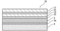
- FIG. 3 is a schematic diagram showing an example of a cross-sectional structure of a power storage device exterior material of the present disclosure.
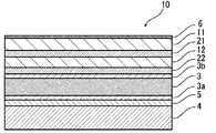
- FIG. 3 is a schematic diagram showing an example of a cross-sectional structure of a power storage device exterior material of the present disclosure.
- FIG. 3 is a schematic diagram showing an example of a cross-sectional structure of a power storage device exterior material of the present disclosure.
- FIG. 3 is a schematic diagram showing an example of a cross-sectional structure of a power storage device exterior material of the present disclosure.
- the exterior material for an electricity storage device of the present disclosure includes at least a first base material layer, a first adhesive layer, a second base material layer, a second adhesive layer, a barrier layer, and a heat-fusible resin layer in this order. It is composed of a laminated body, and the surface of at least one side of the barrier layer is provided with a corrosion resistant film, and the corrosion resistant film was analyzed using time-of-flight secondary ion mass spectrometry. case, CrPO 4 - PO 3 to the peak intensity P CrPO4 derived from - the ratio of the peak intensity P PO3 derived from P PO3 / CrPO4, characterized in that in the range of 6 to 120 or less.
- the exterior material for an electricity storage device and the electricity storage device using the exterior material for an electricity storage device according to the present disclosure will be described in detail.
- the numerical range indicated by “to” means “greater than or equal to” and “less than or equal to.”
- the expression 2 to 15 mm means 2 mm or more and 15 mm or less.
- the exterior material for an electric storage device includes at least a first base material layer 11, a first adhesive layer 21, a second base material layer 12, and a second base material layer 12.
- the laminated body includes the adhesive layer 22, the barrier layer 3, and the heat-fusible resin layer 4 in this order.
- the first base material layer 11 is the outermost layer side
- the heat-fusible resin layer 4 is the innermost layer. That is, at the time of assembling the electricity storage device, the heat-fusible resin layers 4 located on the periphery of the electricity storage device element are heat-sealed to seal the electricity storage device element, whereby the electricity storage device element is sealed.
- the exterior material for an electricity storage device includes an adhesive layer between the barrier layer 3 and the heat-fusible resin layer 4, if necessary, for the purpose of enhancing the adhesiveness between them. 5 may be provided. Further, as shown in FIG. 4, a surface coating layer 6 and the like may be provided on the outer side of the first base material layer 11 (on the side opposite to the heat-fusible resin layer 4 side), if necessary. ..
- FIG. 1 shows a schematic diagram in the case where the exterior material for an electricity storage device of the present disclosure is provided with a corrosion resistant coating 3 a on the surface of the barrier layer 3 on the side of the heat-fusible resin layer 4.
- FIGS. 2 to 4 are schematic diagrams in which the exterior material for an electricity storage device of the present disclosure includes the corrosion-resistant coatings 3 a and 3 b on both surfaces of the barrier layer 3, respectively.
- the corrosion resistant coating 3a may be provided only on the surface of the barrier layer 3 on the side of the heat-fusible resin layer 4, or the barrier layer 3 may be provided.
- the corrosion resistant coating 3b may be provided only on the surface of the second base material layer 12 side, or the corrosion resistant coatings 3a and 3b may be provided on both surfaces of the barrier layer 3, respectively.
- the thickness of the laminate constituting the exterior material 10 for an electricity storage device is not particularly limited, but the upper limit is preferably about 180 ⁇ m or less, about 155 ⁇ m or less, about 120 ⁇ m or less from the viewpoint of cost reduction, energy density improvement and the like.
- the lower limit is preferably about 35 ⁇ m or more, about 45 ⁇ m or more, about 60 ⁇ m or more, from the viewpoint of maintaining the function of the power storage device exterior material of protecting the power storage device element.
- the barrier layer 3 is made of an aluminum alloy foil
- linear streaks called so-called rolling marks are formed on the surface of the aluminum alloy foil in the rolling direction (RD: Rolling Direction) of the aluminum alloy foil. ing. Since the rolling mark extends along the rolling direction, the rolling direction of the aluminum alloy foil can be grasped by observing the surface of the aluminum alloy foil.
- the MD of the laminated body and the RD of the aluminum alloy foil usually match, the surface of the aluminum alloy foil of the laminated body is observed and the rolling direction (RD) of the aluminum alloy foil is observed.
- the MD of the laminated body can be specified.
- the TD of the laminated body is in the direction perpendicular to the MD of the laminated body, the TD of the laminated body can be specified.
- first base material layer 11 and second base material layer 12 are layers provided for the purpose of, for example, exhibiting a function as a base material of the exterior material for an electricity storage device.
- the 1st base material layer 11 is a layer located in the outermost layer side of the exterior material for electrical storage devices.
- the second base material layer 12 is a layer provided between the first base material layer 11 and the barrier layer 3 with a first adhesive layer 21 described later interposed therebetween.
- the materials forming the first base material layer 11 and the second base material layer 12 are not particularly limited as long as they have a function as a base material, that is, at least have an insulating property.
- Each of the first base material layer 11 and the second base material layer 12 can be formed using, for example, a resin, and the resin may include an additive described below.
- the first base material layer 11 and the second base material layer 12 are each formed of a resin
- the first base material layer 11 and the second base material layer 12 are each a resin film formed of a resin, for example. It may be present or may be formed by applying a resin.
- the resin film may be an unstretched film or a stretched film.
- the stretched film include a uniaxially stretched film and a biaxially stretched film, and a biaxially stretched film is preferable.
- the stretching method for forming the biaxially stretched film include a sequential biaxial stretching method, an inflation method and a simultaneous biaxial stretching method.
- the method for applying the resin include a roll coating method, a gravure coating method and an extrusion coating method.
- Examples of the resin forming the first base material layer 11 and the second base material layer 12 include, for example, resins such as polyester, polyamide, polyolefin, epoxy resin, acrylic resin, fluororesin, polyurethane, silicon resin, and phenol resin. , And modified products of these resins.
- the resin forming the first base material layer 11 and the second base material layer 12 may be a copolymer of these resins or a modified product of the copolymer. Further, it may be a mixture of these resins.
- polyester and polyamide are preferably used as the resins forming the first base material layer 11 and the second base material layer 12.
- polyester examples include polyethylene terephthalate, polybutylene terephthalate, polyethylene naphthalate, polybutylene naphthalate, polyethylene isophthalate, and copolyester.
- copolyester examples include a copolyester having ethylene terephthalate as a main repeating unit.
- a copolymer polyester (hereinafter, abbreviated to polyethylene (terephthalate/isophthalate)) in which ethylene terephthalate is a main repeating unit and is polymerized with ethylene isophthalate, polyethylene (terephthalate/adipate), polyethylene (terephthalate/ Sodium sulfoisophthalate), polyethylene (terephthalate/sodium isophthalate), polyethylene (terephthalate/phenyl-dicarboxylate), polyethylene (terephthalate/decanedicarboxylate), and the like.
- These polyesters may be used alone or in combination of two or more.
- polyamides include aliphatic polyamides such as nylon 6, nylon 66, nylon 610, nylon 12, nylon 46, and copolymers of nylon 6 and nylon 66; terephthalic acid and/or isophthalic acid.
- Hexamethylenediamine-isophthalic acid-terephthalic acid copolyamides such as nylon 6I, nylon 6T, nylon 6IT, nylon 6I6T (I represents isophthalic acid, T represents terephthalic acid) containing a constitutional unit derived therefrom, polyamide MXD6 (polymeta Polyamides containing aromatic compounds such as silylene adipamide; alicyclic polyamides such as polyamide PACM6 (polybis(4-aminocyclohexyl)methane adipamide); lactam components and isocyanate components such as 4,4′-diphenylmethane-diisocyanate Examples thereof include copolymerized polyamides, polyesteramide copolymers and polyetheresteramide copoly
- the first base material layer 11 and the second base material layer 12 preferably include at least one of polyamide and polyester. Further, from the viewpoint of further improving moldability, it is more preferable that the first base material layer 11 contains at least one of polyamide and polyester, and the second base material layer 12 contains polyamide. It is preferable that the base material layer 11 and the second base material layer 12 contain polyamide, and it is further preferable that the first base material layer 11 and the second base material layer 12 are made of polyamide.
- the first base material layer 11 and the second base material layer 12 preferably each include at least one of a polyester film, a polyamide film, and a polyolefin film, and include a stretched polyester film, a stretched polyamide film, and a stretched polyolefin film. It is preferable to include at least one of them, and it is more preferable to include at least one of a stretched polyethylene terephthalate film, a stretched polybutylene terephthalate film, a stretched nylon film, and a stretched polypropylene film.
- Biaxially stretched polyethylene terephthalate film biaxially stretched It is more preferable to include at least one of a polybutylene terephthalate film, a biaxially oriented nylon film, and a biaxially oriented polypropylene film.
- the combination of the first base material layer 11 and the second base material layer 12 preferably include polyester film and nylon film, nylon film and nylon film, polyester film and polyester film, and more preferably, Examples include stretched nylon film and stretched polyester film, stretched nylon film and stretched nylon film, stretched polyester film and stretched polyester film.
- the polyester film is preferably a polyethylene terephthalate film.
- a lubricant for at least one of the surface and the inside of the first base material layer 11 and the second base material layer 12, a lubricant, a flame retardant, an antiblocking agent, an antioxidant, a light stabilizer, a tackifier, and an antistatic property, respectively.
- Additives such as agents may be present. As the additive, only one kind may be used, or two or more kinds may be mixed and used.
- a lubricant is preferably present on the surface of the first base material layer 11 from the viewpoint of enhancing the moldability of the exterior material for an electricity storage device.
- the lubricant is not particularly limited, but preferably an amide lubricant is used.
- Specific examples of the amide-based lubricant include saturated fatty acid amide, unsaturated fatty acid amide, substituted amide, methylol amide, saturated fatty acid bisamide, unsaturated fatty acid bisamide, fatty acid ester amide, aromatic bisamide, and the like.
- Specific examples of the saturated fatty acid amide include lauric acid amide, palmitic acid amide, stearic acid amide, behenic acid amide, and hydroxystearic acid amide.
- unsaturated fatty acid amides include oleic acid amide and erucic acid amide.
- substituted amide include N-oleylpalmitic acid amide, N-stearyl stearic acid amide, N-stearyl oleic acid amide, N-oleyl stearic acid amide, and N-stearyl erucic acid amide.
- methylolamide include methylolstearic acid amide.
- saturated fatty acid bisamide examples include methylenebisstearic acid amide, ethylenebiscapric acid amide, ethylenebislauric acid amide, ethylenebisstearic acid amide, ethylenebishydroxystearic acid amide, ethylenebisbehenic acid amide, and hexamethylenebisstearic acid amide.
- saturated fatty acid bisamide examples include acid amide, hexamethylene bisbehenic acid amide, hexamethylene hydroxystearic acid amide, N,N′-distearyl adipic acid amide and N,N′-distearyl sebacic acid amide.
- the unsaturated fatty acid bisamide include ethylene bisoleic acid amide, ethylene bis erucic acid amide, hexamethylene bis oleic acid amide, N,N′-dioleyl adipate amide, N,N′-dioleyl sebacic acid amide. And so on.
- Specific examples of the fatty acid ester amide include stearoamide ethyl stearate.
- specific examples of the aromatic bisamide include m-xylylenebisstearic acid amide, m-xylylenebishydroxystearic acid amide, N,N'-distearylisophthalic acid amide and the like.
- the lubricant may be used alone or in combination of two or more.
- the lubricant When the lubricant is present on the surface of the first base material layer 11, its amount is not particularly limited, but is preferably about 3 mg/m 2 or more, more preferably about 4 to 15 mg/m 2 , and further preferably 5 It may be about 14 mg/m 2 .
- the lubricant present on the surface of the first base material layer 11 may be one in which the lubricant contained in the resin forming the first base material layer 11 is exuded, or on the surface of the first base material layer 11. It may be coated with a lubricant.
- the thickness of the first base material layer 11 is preferably about 10 ⁇ m or more, more preferably about 12 ⁇ m or more, and also preferably from the viewpoint of improving the moldability while making the exterior material for an electricity storage device thin. Is about 20 ⁇ m or less, more preferably about 18 ⁇ m or less, further preferably about 15 ⁇ m or less, and a preferable range is about 10 to 20 ⁇ m, about 10 to 18 ⁇ m, about 10 to 15 ⁇ m, about 12 to 20 ⁇ m, 12 to 18 ⁇ m. And about 12 to 15 ⁇ m.
- the thickness of the second base material layer 12 is preferably about 12 ⁇ m or more, more preferably about 15 ⁇ m or more, preferably about 30 ⁇ m or less, more preferably about 28 ⁇ m or less, and further preferably The thickness is about 25 ⁇ m or less, and preferable ranges are about 12 to 30 ⁇ m, about 12 to 28 ⁇ m, about 12 to 25 ⁇ m, about 15 to 30 ⁇ m, about 15 to 28 ⁇ m, about 15 to 25 ⁇ m.
- the total thickness of the first base material layer 11 and the second base material layer 12 is preferably about 20 ⁇ m or more, more preferably about 25 ⁇ m or more, further preferably about 28 ⁇ m or more, and preferably It is about 50 ⁇ m or less, more preferably about 45 ⁇ m or less, further preferably about 40 ⁇ m or less, further preferably about 35 ⁇ m or less, and the preferable range is about 20 to 50 ⁇ m, about 20 to 45 ⁇ m, about 20 to 40 ⁇ m, 20 to Examples include about 35 ⁇ m, about 25 to 50 ⁇ m, about 25 to 45 ⁇ m, about 25 to 40 ⁇ m, about 25 to 35 ⁇ m, about 28 to 50 ⁇ m, about 28 to 45 ⁇ m, about 28 to 40 ⁇ m, about 28 to 35 ⁇ m.
- the first base material layer 11, the first adhesive layer 21, and the first adhesive layer 21 are provided on the opposite side (outer layer side) to the barrier layer 3 side of the second adhesive layer 22 described later.
- other layers may be further provided.
- the materials forming the other layers are not particularly limited as long as they have insulating properties. Examples of the material for forming the other layer include polyester, polyamide, epoxy resin, acrylic resin, fluororesin, polyurethane, silicon resin, phenol resin, polyetherimide, polyimide, and mixtures and copolymers thereof.
- the thickness of the other layer is preferably about 0.1 to 20 ⁇ m, more preferably about 0.5 to 10 ⁇ m.
- the first adhesive layer 21 is a layer provided to bond the first base material layer 11 and the second base material layer 12.
- the hardness of the first adhesive layer 21 and the hardness of the second adhesive layer 22 described below are preferably 20 MPa or more, respectively. Thereby, particularly excellent moldability is exhibited in the exterior material for an electricity storage device in which the base material layer is formed of a plurality of layers (that is, the first base material layer 11 and the second base material layer 12). More specifically, when the hardness of each of the first adhesive layer 21 and the second adhesive layer 22 measured by the nanoindentation method is 20 MPa or more, particularly excellent moldability is exhibited.
- the hardness of the first adhesive layer 21 is more preferably 30 MPa or more, further preferably 51 MPa or more, and preferably 400 MPa or less, more preferably 350 MPa or less. Are listed. Preferable ranges of the hardness of the first adhesive layer 21 include about 20 to 400 MPa, about 20 to 350 MPa, about 30 to 400 MPa, about 30 to 350 MPa, about 51 to 400 MPa, about 51 to 350 MPa.
- the hardness of each of the first adhesive layer 21 and the second adhesive layer 22 measured by the nanoindentation method is a value measured as follows.
- a nanoindenter (“TriboIndenter TI950” manufactured by HYSITRON (Hyditron) Co., Ltd.) is used as an apparatus.
- a Berkovich indenter (triangular pyramid) is used as an indenter of the nanoindenter.
- Hardness of the second adhesive layer 22 For, regarding the relative humidity of 50% and 23° C. environment, the indenter is the surface of the second adhesive layer 22 of the exterior material for an electricity storage device (the surface where the second adhesive layer 22 is exposed, and the lamination of each layer).
- the indenter is pushed into the adhesive layer from the surface to a load of 40 ⁇ N for 10 seconds, the state is held for 5 seconds, and then the load is removed for 10 seconds.
- the indentation hardness (MPa) is calculated from P max /A using max ( ⁇ N) and the projected contact area A ( ⁇ m 2 ) at the maximum depth, and the hardness of the first adhesive layer 21. Is measured in the same manner as the second adhesive layer 22 except that the load is 10 ⁇ N.
- the hardness of the first adhesive layer 21 includes not only the type of resin contained in the adhesive, but also the molecular weight of the resin, the number of cross-linking points, the ratio of the main agent and the curing agent, the dilution ratio of the main agent and the curing agent, the drying temperature, By adjusting the aging temperature, the aging time, etc., the above values can be adjusted.
- the adhesive used for forming the first adhesive layer 21 is not limited, but may be any of a chemical reaction type, a solvent volatilization type, a heat melting type, a heat pressure type, and the like. Further, it may be a two-component curing type adhesive (two-component adhesive), a one-component curing type adhesive (one-component adhesive), or a resin that does not undergo a curing reaction.
- the first adhesive layer 21 may be a single layer or a multilayer.
- the adhesive component contained in the first adhesive layer 21 include polyesters such as polyethylene terephthalate, polybutylene terephthalate, polyethylene naphthalate, polybutylene naphthalate, polyethylene isophthalate and copolyester; polyether; polyurethane.
- These adhesive components may be used alone or in combination of two or more. Among these adhesive components, a polyurethane adhesive is preferable.
- the resin serving as the adhesive component may be used in combination with an appropriate curing agent to enhance the adhesive strength.
- the curing agent is appropriately selected from polyisocyanates, polyfunctional epoxy resins, oxazoline group-containing polymers, polyamine resins, acid anhydrides, etc. depending on the functional groups of the adhesive component.
- the polyurethane adhesive includes, for example, a polyurethane adhesive containing a base compound containing a polyol compound and a curing agent containing an isocyanate compound.
- a polyurethane adhesive containing a base compound containing a polyol compound and a curing agent containing an isocyanate compound.
- Preferred is a two-component curing type polyurethane adhesive containing a polyol such as a polyester polyol, a polyether polyol and an acrylic polyol as a main component and an aromatic or aliphatic polyisocyanate as a curing agent.
- a polyester polyol having a hydroxyl group at the side chain in addition to the hydroxyl group at the terminal of the repeating unit.
- the first adhesive layer 21 is made of a polyurethane adhesive, excellent electrolytic solution resistance is imparted to the exterior material for an electricity storage device, and the first base material layer 11 is peeled off even when the electrolytic solution adheres to the side surface. Is suppressed.
- the first adhesive layer 21 may contain other components as long as it does not impair the adhesiveness, and may contain a colorant, a thermoplastic elastomer, a tackifier, a filler, and the like. Since the first adhesive layer 21 contains the coloring agent, the exterior material for the electricity storage device can be colored. Known colorants such as pigments and dyes can be used as the colorant. Moreover, only one type of colorant may be used, or two or more types may be mixed and used.
- the type of pigment is not particularly limited as long as it does not impair the adhesiveness of the first adhesive layer 21.
- organic pigments include azo, phthalocyanine, quinacridone, anthraquinone, dioxazine, indigothioindigo, perinone-perylene, isoindolenin, benzimidazolone pigments, and the like.
- the pigment include carbon black pigments, titanium oxide pigments, cadmium pigments, lead pigments, chromium oxide pigments, iron pigments and the like, and mica (mica) fine powder, fish scale foil and the like.
- colorants for example, carbon black is preferable in order to make the exterior material of the electricity storage device have a black appearance.
- the average particle diameter of the pigment is not particularly limited and may be, for example, about 0.05 to 5 ⁇ m, preferably about 0.08 to 2 ⁇ m.
- the average particle size of the pigment is the median size measured by a laser diffraction/scattering particle size distribution measuring device.
- the content of the pigment in the first adhesive layer 21 is not particularly limited as long as the exterior material for the electricity storage device is colored, and is, for example, about 5 to 60% by mass, preferably 10 to 40% by mass.
- the thickness of the first adhesive layer 21 is preferably 5 ⁇ m or less, and preferably about 1 to 5 ⁇ m from the viewpoint of improving the moldability while reducing the thickness of the exterior material for an electricity storage device.
- the second adhesive layer 22 is a layer provided to bond the second base material layer 12 and the barrier layer 3.
- the hardness of the first adhesive layer 21 and the hardness of the second adhesive layer 22 are each 20 MPa or more.
- the base material layer is formed of a plurality of layers (that is, the first base material layer 11 and the second base material layer 12). More specifically, when the hardness of each of the first adhesive layer 21 and the second adhesive layer 22 measured by the nanoindentation method is 20 MPa or more, particularly excellent moldability is exhibited.
- the hardness of the second adhesive layer 22 is more preferably 30 MPa or more, further preferably 51 MPa or more, and preferably 400 MPa or less, more preferably 350 MPa. These include: Preferable ranges of the hardness of the second adhesive layer 22 include about 20 to 400 MPa, about 20 to 350 MPa, about 30 to 400 MPa, about 30 to 350 MPa, about 51 to 400 MPa, about 51 to 350 MPa.
- the hardness of the second adhesive layer 22 measured by the nanoindentation method is a value measured by the above method.
- the hardness of the second adhesive layer 22 is similar to that of the first adhesive layer 21 described above, not only the type of resin contained in the adhesive, but also the molecular weight of the resin, the number of cross-linking points, the ratio of the main agent and the curing agent, By adjusting the dilution ratio of the main agent and the curing agent, the drying temperature, the aging temperature, the aging time, etc., the above values can be adjusted.
- the adhesive used to form the second adhesive layer 22 is not particularly limited as long as it can provide the second adhesive layer 22 with the hardness described above, and the first adhesive described above is used.
- the same thing as the layer 21 is illustrated. That is, as specific examples of the adhesive component and the adhesive that can be used for forming the second adhesive layer 22, the same as the above-mentioned first adhesive layer 21 is exemplified.
- the second adhesive layer 22 may include a colorant, a thermoplastic elastomer, a tackifier, a filler, and the like. Since the second adhesive layer 22 contains the colorant, the power storage device exterior material can be colored. Known colorants such as pigments and dyes can be used as the colorant. Moreover, only one type of colorant may be used, or two or more types may be mixed and used.
- colorants for example, carbon black is preferable in order to make the exterior material of the electricity storage device have a black appearance.
- the average particle diameter of the pigment is not particularly limited and may be, for example, about 0.05 to 5 ⁇ m, preferably about 0.08 to 2 ⁇ m.
- the average particle size of the pigment is the median size measured by a laser diffraction/scattering particle size distribution measuring device.
- the content of the pigment in the second adhesive layer 22 is not particularly limited as long as the exterior material for the electricity storage device is colored, and is, for example, about 5 to 60% by mass, preferably 10 to 40% by mass.
- the thickness of the second adhesive layer 22 is preferably 5 ⁇ m or less, and preferably about 1 to 5 ⁇ m from the viewpoint of improving the moldability while reducing the thickness of the exterior material for an electricity storage device.
- the colored layer is, for example, a layer provided between the second base material layer 12 and the barrier layer 3 as necessary (not shown).
- the colored layer may be provided between the second base material layer 12 and the second adhesive layer 22, and between the second adhesive layer 22 and the barrier layer 3.
- a colored layer may be provided outside the second base material layer 12.
- the colored layer can be formed, for example, by applying an ink containing a coloring agent to the surface of the second base material layer 12, the surface of the barrier layer 3, or the like.
- a coloring agent such as pigments and dyes can be used as the colorant.
- only one type of colorant may be used, or two or more types may be mixed and used.
- coloring agent contained in the coloring layer are the same as those exemplified in the section of [First adhesive layer 21].
- the barrier layer 3 is a layer that suppresses at least entry of moisture.
- the barrier layer 3 examples include a metal foil having a barrier property, a vapor deposition film, a resin layer, and the like.
- the vapor deposition film may be a metal vapor deposition film, an inorganic oxide vapor deposition film, a carbon-containing inorganic oxide vapor deposition film, or the like
- the resin layer may be polyvinylidene chloride, chlorotrifluoroethylene (CTFE)-based polymers or tetra- Examples thereof include polymers containing fluoroethylene (TFE) as a main component, polymers having a fluoroalkyl group, fluorine-containing resins such as polymers having a fluoroalkyl unit as a main component, and ethylene vinyl alcohol copolymers.
- CTFE chlorotrifluoroethylene
- barrier layer 3 a resin film provided with at least one of the vapor deposition film and the resin layer may be used.
- a plurality of barrier layers 3 may be provided.
- the barrier layer 3 preferably includes a layer made of a metal material. Specific examples of the metal material forming the barrier layer 3 include aluminum alloys, stainless steels, titanium steels, and steel plates. When used as metal foils, at least one of aluminum alloy foils and stainless steel foils is included. It is preferable.
- the aluminum alloy foil is, from the viewpoint of improving the formability of the exterior material for an electricity storage device, for example, a soft aluminum alloy foil composed of annealed aluminum alloy or the like is more preferable, and the formability is further improved. Therefore, the aluminum alloy foil containing iron is preferable.
- the content of iron is preferably 0.1 to 9.0% by mass, and more preferably 0.5 to 2.0% by mass.
- the iron content is 0.1% by mass or more, it is possible to obtain an outer casing material for an electricity storage device having more excellent moldability.
- the iron content is 9.0 mass% or less, it is possible to obtain a more flexible outer packaging material for an electricity storage device.
- the soft aluminum alloy foil for example, an aluminum alloy having a composition defined by JIS H4160:1994 A8021H-O, JIS H4160:1994 A8079H-O, JIS H4000:2014 A8021P-O, or JIS H4000:2014 A8079P-O.
- Foil can be mentioned. If necessary, silicon, magnesium, copper, manganese, etc. may be added.
- the softening can be performed by annealing treatment or the like.
- examples of stainless steel foils include austenite-based, ferrite-based, austenite-ferrite-based, martensite-based, and precipitation-hardening-based stainless steel foils. Further, from the viewpoint of providing an exterior material for an electricity storage device having excellent moldability, the stainless steel foil is preferably made of austenitic stainless steel.
- SUS304, SUS301, SUS316L and the like are specific examples of the austenitic stainless steel forming the stainless steel foil, and among these, SUS304 is particularly preferable.
- the thickness of the barrier layer 3 may at least exhibit a function as a barrier layer that suppresses the infiltration of moisture, and is, for example, about 9 to 200 ⁇ m.
- the upper limit is preferably about 85 ⁇ m or less, more preferably about 50 ⁇ m or less, further preferably about 40 ⁇ m or less, particularly preferably about 35 ⁇ m or less, and the lower limit is preferably about.
- the preferable range of the thickness is about 10 to 85 ⁇ m, about 10 to 50 ⁇ m, about 10 to 40 ⁇ m, about 10 to 35 ⁇ m, 20 to Examples include about 85 ⁇ m, about 20 to 50 ⁇ m, about 20 to 40 ⁇ m, about 20 to 35 ⁇ m, about 25 to 85 ⁇ m, about 25 to 50 ⁇ m, about 25 to 40 ⁇ m, about 25 to 35 ⁇ m. Of these, about 25 to 50 ⁇ m, Furthermore, about 25 to 40 ⁇ m is particularly preferable. When the barrier layer 3 is made of an aluminum alloy foil, the above range is particularly preferable.
- the upper limit of the thickness of the stainless steel foil is preferably about 60 ⁇ m or less, more preferably about 50 ⁇ m or less, further preferably about 40 ⁇ m or less, It is more preferably about 30 ⁇ m or less, particularly preferably about 25 ⁇ m or less, the lower limit is preferably about 10 ⁇ m or more, more preferably about 15 ⁇ m or more, and the preferable thickness range is about 10 to 60 ⁇ m. ⁇ 50 ⁇ m, about 10-40 ⁇ m, about 10-30 ⁇ m, about 10-25 ⁇ m, about 15-60 ⁇ m, about 15-50 ⁇ m, about 15-40 ⁇ m, about 15-30 ⁇ m, about 15-25 ⁇ m.
- the barrier layer 3 is provided with a corrosion resistant film on at least one surface thereof.
- the corrosion resistant coating 3 a may be provided only on the surface of the barrier layer 3 on the side of the heat-fusible resin layer 4, or the second base material layer of the barrier layer 3. Only the surface on the 12th side may be provided with the corrosion resistant coating 3b, or both surfaces of the barrier layer 3 may be provided with the corrosion resistant coatings 3a and 3b, respectively.
- the peak intensity ratio P PO3 /CrPO4 in the corrosion-resistant coating on either surface may be within the above range.
- the peak intensity ratio P PO3 /CrPO 4 of each of the corrosion resistant films 3 a and 3 b is within the above range.
- the corrosion-resistant film located on the heat-fusible resin layer side of the barrier layer and the layer adjacent to this for example, an adhesive layer, a heat-fusible resin layer, etc.
- the exterior material for an electricity storage device of the present disclosure is provided with the corrosion-resistant coating 3a on at least the surface of the barrier layer 3 on the heat-fusible resin layer 4 side. It is preferable that the peak intensity ratio P PO3 /CrPO4 of the corrosion resistant coating 3a be within the above range. Regarding these points, the same applies to each peak intensity ratio shown below.
- the ratio P PO3 /CrPO4 of the peak intensity P PO3 derived from PO 3 ⁇ to the peak intensity P CrPO4 derived from CrPO 4 ⁇ may be in the range of 6 to 120, but is provided with a corrosion resistant film.
- the lower limit of the ratio P PO3 /CrPO4 is about 10 or more, and the upper limit is preferably about 115 or less, more preferably about 110 or less, and further preferably about 10 or less. 50 or less are mentioned.
- the preferable range of the ratio P PO3 /CrPO4 is about 6 to 115, about 6 to 110, about 6 to 50, about 10 to 120, about 10 to 115, about 10 to 110, about 10 to 50.
- the method for analyzing the corrosion resistant coatings 3a and 3b by using the time-of-flight secondary ion mass spectrometry is specifically performed by using a time-of-flight secondary ion mass spectrometer under the following measurement conditions. be able to.
- the corrosion resistant film contains chromium can be confirmed using X-ray photoelectron spectroscopy. Specifically, first, in the exterior material for an electricity storage device, the layers (adhesive layer, heat-fusible resin layer, adhesive layer, etc.) laminated on the barrier layer are physically peeled off. Next, the barrier layer is placed in an electric furnace, and the organic component existing on the surface of the barrier layer is removed at about 300° C. for about 30 minutes. Then, it is confirmed that chromium is contained by using X-ray photoelectron spectroscopy of the surface of the barrier layer.
- the corrosion resistant films 3a and 3b can be formed by subjecting the surface of the barrier layer 3 to chemical conversion treatment with a treatment liquid containing a chromium compound such as chromium oxide.
- a treatment liquid containing a chromium compound for example, phosphoric acid and/or its salt in which a chromium compound such as chromium oxide is dispersed is applied to the surface of the barrier layer 3 and baked.
- a method of forming a corrosion resistant film on the surface of the barrier layer 3 by carrying out the method can be mentioned.
- the peak intensity ratio P PO3 /CrPO4 of the corrosion resistant coatings 3a and 3b is adjusted by, for example, the composition of the treatment liquid forming the corrosion resistant coatings 3a and 3b, the manufacturing conditions such as the temperature and time of the baking treatment after the treatment, and the like. can do.
- the ratio of the chromium compound to the phosphoric acid and/or its salt in the treatment liquid containing the chromium compound is not particularly limited, but from the viewpoint of setting the peak intensity ratio P PO3 /CrPO4 within the above range, the chromium compound is
- the ratio of phosphoric acid and/or its salt to 100 parts by mass is preferably about 30 to 120 parts by mass, more preferably about 40 to 110 parts by mass.
- the phosphoric acid and its salt for example, condensed phosphoric acid and its salt can also be used.
- the treatment liquid containing the chromium compound may further contain an anionic polymer and a crosslinking agent for crosslinking the anionic polymer.
- the anionic polymer include poly(meth)acrylic acid or a salt thereof, a copolymer containing (meth)acrylic acid or a salt thereof as a main component, and the like.
- the cross-linking agent include compounds having a functional group of any one of an isocyanate group, a glycidyl group, a carboxyl group and an oxazoline group, and a silane coupling agent.
- the anionic polymer and the cross-linking agent may each be one type or two or more types.
- the treatment liquid containing the chromium compound contains an aminated phenol polymer.
- the content of the aminated phenol polymer is preferably about 100 to 400 parts by mass, more preferably about 200 to 300 parts by mass with respect to 100 parts by mass of the chromium compound.
- the weight average molecular weight of the aminated phenol polymer is preferably about 5,000 to 20,000.
- the weight average molecular weight of the aminated phenol polymer is a value measured by gel permeation chromatography (GPC), which was measured under the condition that polystyrene was used as a standard sample.
- the solvent of the treatment liquid containing the chromium compound is not particularly limited as long as it can evaporate the components contained in the treatment liquid by subsequent heating, but water is preferable.
- the solid content concentration of the chromium compound contained in the treatment liquid for forming the corrosion resistant film is not particularly limited, but the peak strength ratio P PO3 /CrPO 4 is set in the above predetermined range to obtain excellent corrosion resistance. From the viewpoint of enhancing the adhesion of the barrier layer provided with the corrosion resistant film while exhibiting, for example, about 1 to 15% by mass, preferably about 7.0 to 12.0% by mass, and more preferably 8.0 to 11% by mass. The amount is preferably about 0.0% by mass, more preferably about 9.0 to 10.0% by mass.
- the thickness of the corrosion resistant film is not particularly limited, but from the viewpoint of enhancing the adhesion of the barrier layer provided with the corrosion resistant film while exhibiting excellent corrosion resistance, it is preferably about 1 nm to 10 ⁇ m, more preferably The thickness is preferably about 1 to 100 nm, more preferably about 1 to 50 nm.
- the thickness of the corrosion-resistant coating can be measured by observation with a transmission electron microscope, or a combination of observation with a transmission electron microscope and energy dispersive X-ray spectroscopy or electron beam energy loss spectroscopy.
- the amount of the corrosion resistant film per 1 m 2 of the surface of the barrier layer 3 is preferably about 1 to 500 mg, more preferably about 1 to 100 mg, and further preferably about 1 to 50 mg.
- Examples of the method of applying the treatment liquid containing the chromium compound to the surface of the barrier layer include a bar coating method, a roll coating method, a gravure coating method and a dipping method.
- the treatment liquid is baked from the viewpoint of enhancing the adhesion of the barrier layer provided with the corrosion resistant film while exhibiting excellent corrosion resistance.
- the heating temperature for forming a corrosion-resistant film is preferably about 170 to 250°C, more preferably about 180 to 230°C, and further preferably about 190 to 220°C. From the same viewpoint, the baking time is preferably about 2 to 10 seconds, more preferably about 3 to 6 seconds.
- an alkali dipping method an electrolytic cleaning method, an acid cleaning method, an electrolytic acid cleaning method, an acid is used.
- Degreasing treatment is preferably performed by a known treatment method such as an activation method.
- the heat-fusible resin layer 4 corresponds to the innermost layer, and the heat-fusible resin layers are heat-fused to each other during assembly of the electricity storage device to seal the electricity storage device element. It is a layer (sealant layer) that exerts.
- the resin constituting the heat-fusible resin layer 4 is not particularly limited as long as it can be heat-bonded, but a resin containing a polyolefin skeleton such as polyolefin or acid-modified polyolefin is preferable.
- a resin containing a polyolefin skeleton such as polyolefin or acid-modified polyolefin is preferable.
- the fact that the resin constituting the heat-fusible resin layer 4 contains a polyolefin skeleton can be analyzed by, for example, infrared spectroscopy, gas chromatography mass spectrometry, or the like. Further, when the resin forming the heat-fusible resin layer 4 is analyzed by infrared spectroscopy, it is preferable that a peak derived from maleic anhydride is detected.
- a peak derived from maleic acid is detected in the vicinity of the wave number of 1760 cm -1 and near the wave number 1780 cm -1.
- the heat-fusible resin layer 4 is a layer composed of a maleic anhydride-modified polyolefin
- a peak derived from maleic anhydride is detected when measured by infrared spectroscopy.
- the degree of acid modification is low, the peak may be too small to be detected. In that case, it can be analyzed by nuclear magnetic resonance spectroscopy.
- polystyrene resin examples include polyethylene such as low-density polyethylene, medium-density polyethylene, high-density polyethylene, and linear low-density polyethylene; ethylene- ⁇ olefin copolymers; homopolypropylene, polypropylene block copolymers (for example, propylene and Examples thereof include polypropylene block copolymers of ethylene) and polypropylene random copolymers (for example, random copolymers of propylene and ethylene); propylene- ⁇ -olefin copolymers; terpolymers of ethylene-butene-propylene. Of these, polypropylene is preferred.
- the polyolefin resin is a copolymer, it may be a block copolymer or a random copolymer. These polyolefin resins may be used alone or in combination of two or more.
- the polyolefin may be a cyclic polyolefin.
- the cyclic polyolefin is a copolymer of an olefin and a cyclic monomer, and examples of the olefin which is a constituent monomer of the cyclic polyolefin include ethylene, propylene, 4-methyl-1-pentene, styrene, butadiene and isoprene.
- cyclic monomer which is a constituent monomer of the cyclic polyolefin examples include cyclic alkenes such as norbornene; and cyclic dienes such as cyclopentadiene, dicyclopentadiene, cyclohexadiene and norbornadiene. Of these, cyclic alkenes are preferable, and norbornene is more preferable.
- ⁇ Acid-modified polyolefin is a polymer modified by block or graft polymerization of polyolefin with an acid component.
- the acid-modified polyolefin the above-mentioned polyolefin, a copolymer obtained by copolymerizing the above-mentioned polyolefin with a polar molecule such as acrylic acid or methacrylic acid, or a polymer such as a cross-linked polyolefin can be used.
- the acid component used for acid modification include carboxylic acids such as maleic acid, acrylic acid, itaconic acid, crotonic acid, maleic anhydride, and itaconic anhydride, or anhydrides thereof.
- the acid-modified polyolefin may be an acid-modified cyclic polyolefin.
- the acid-modified cyclic polyolefin is a polymer obtained by copolymerizing a part of the monomers constituting the cyclic polyolefin in place of the acid component, or by block-polymerizing or graft-polymerizing the acid component with respect to the cyclic polyolefin. is there.
- the acid-modified cyclic polyolefin is the same as described above.
- the acid component used for the acid modification is the same as the acid component used for the modification of the polyolefin.
- Preferred acid-modified polyolefins include polyolefins modified with carboxylic acids or their anhydrides, polypropylene modified with carboxylic acids or their anhydrides, maleic anhydride-modified polyolefins, maleic anhydride-modified polypropylenes.
- the heat-fusible resin layer 4 may be formed of one type of resin alone, or may be formed of a blend polymer in which two or more types of resins are combined. Further, the heat-fusible resin layer 4 may be formed of only one layer, but may be formed of two or more layers of the same or different resin.
- the heat-fusible resin layer 4 may contain a lubricant and the like, if necessary.
- the heat-fusible resin layer 4 contains a lubricant, the moldability of the exterior material for an electricity storage device can be improved.
- the lubricant is not particularly limited, and a known lubricant can be used.
- the lubricant may be used singly or in combination of two or more.
- the lubricant is not particularly limited, but an amide lubricant is preferable. Specific examples of the lubricant include those exemplified for the first base material layer 11. The lubricant may be used alone or in combination of two or more.
- the lubricant is present on the surface of the heat-fusible resin layer 4, its amount is not particularly limited, but from the viewpoint of enhancing the moldability of the exterior material for an electricity storage device, it is preferably about 10 to 50 mg/m 2. And more preferably about 15 to 40 mg/m 2 .
- the lubricant present on the surface of the heat-fusible resin layer 4 may be one in which the lubricant contained in the resin forming the heat-fusible resin layer 4 is exuded, or The surface may be coated with a lubricant.
- the thickness of the heat-fusible resin layer 4 is not particularly limited as long as the heat-fusible resin layers have a function of heat-sealing each other and sealing the electricity storage device element, but for example, about 100 ⁇ m or less, preferably The thickness is about 85 ⁇ m or less, more preferably about 15 to 85 ⁇ m.
- the thickness of the heat-fusible resin layer 4 is preferably about 85 ⁇ m or less, more preferably about 15 to 45 ⁇ m.
- the thickness of the heat-fusible resin layer 4 is preferably about 20 ⁇ m or more, more preferably 35 to 85 ⁇ m. The degree can be mentioned.
- the adhesive layer 5 is provided between the barrier layer 3 (or the corrosion resistant film) and the heat-fusible resin layer 4 as necessary in order to firmly bond them together. It is a layer.
- the adhesive layer 5 is formed of a resin that can bond the barrier layer 3 and the heat-fusible resin layer 4.
- the resin used for forming the adhesive layer 5 for example, the same adhesives as those exemplified for the first adhesive layer 21 can be used.
- the resin used for forming the adhesive layer 5 preferably contains a polyolefin skeleton, and examples thereof include the polyolefins and the acid-modified polyolefins exemplified in the above heat-fusible resin layer 4.
- the fact that the resin constituting the adhesive layer 5 contains a polyolefin skeleton can be analyzed by, for example, infrared spectroscopy, gas chromatography mass spectrometry, etc., and the analysis method is not particularly limited.
- a peak derived from maleic anhydride is detected.
- a peak derived from maleic acid is detected in the vicinity of the wave number of 1760 cm -1 and near the wave number 1780 cm -1.
- the peak may be too small to be detected. In that case, it can be analyzed by nuclear magnetic resonance spectroscopy.
- the adhesive layer 5 preferably contains an acid-modified polyolefin.
- an acid-modified polyolefin a polyolefin modified with a carboxylic acid or an anhydride thereof, a polypropylene modified with a carboxylic acid or an anhydride thereof, a maleic anhydride modified polyolefin, and a maleic anhydride modified polypropylene are particularly preferable.
- the adhesive layer 5 is a resin composition containing an acid-modified polyolefin and a curing agent. It is more preferable that the cured product is.
- the acid-modified polyolefin those mentioned above can be preferably exemplified.
- the adhesive layer 5 is a cured product of a resin composition containing an acid-modified polyolefin and at least one selected from the group consisting of a compound having an isocyanate group, a compound having an oxazoline group, and a compound having an epoxy group. It is preferable that the cured product be a resin composition containing an acid-modified polyolefin and at least one selected from the group consisting of a compound having an isocyanate group and a compound having an epoxy group.
- the adhesive layer 5 preferably contains at least one selected from the group consisting of polyurethane, polyester, and epoxy resin, and more preferably contains polyurethane and epoxy resin.
- the polyester for example, an amide ester resin is preferable.
- the amide ester resin is generally produced by the reaction of a carboxyl group and an oxazoline group.
- the adhesive layer 5 is more preferably a cured product of a resin composition containing at least one of these resins and the acid-modified polyolefin.
- unreacted compounds such as a compound having an isocyanate group, a compound having an oxazoline group, and a curing agent such as an epoxy resin remain in the adhesive layer 5, the presence of the unreacted product is determined by infrared spectroscopy, for example. It can be confirmed by a method selected from Raman spectroscopy, time-of-flight secondary ion mass spectrometry (TOF-SIMS), and the like.
- the adhesive layer 5 is at least selected from the group consisting of an oxygen atom, a heterocycle, a C ⁇ N bond, and a C—O—C bond. It is preferably a cured product of a resin composition containing one type of curing agent.
- the curing agent having a heterocycle include a curing agent having an oxazoline group and a curing agent having an epoxy group.
- examples of the curing agent having a C—O—C bond include a curing agent having an oxazoline group, a curing agent having an epoxy group, and polyurethane.
- the fact that the adhesive layer 5 is a cured product of a resin composition containing these curing agents means, for example, gas chromatograph mass spectrometry (GCMS), infrared spectroscopy (IR), time-of-flight secondary ion mass spectrometry (TOF). -SIMS), X-ray photoelectron spectroscopy (XPS) and the like.
- GCMS gas chromatograph mass spectrometry
- IR infrared spectroscopy
- TOF time-of-flight secondary ion mass spectrometry
- -SIMS X-ray photoelectron spectroscopy
- the compound having an isocyanate group is not particularly limited, but from the viewpoint of effectively enhancing the adhesion between the barrier layer 3 and the adhesive layer 5, a polyfunctional isocyanate compound is preferable.
- the polyfunctional isocyanate compound is not particularly limited as long as it is a compound having two or more isocyanate groups.
- Specific examples of the polyfunctional isocyanate-based curing agent include pentane diisocyanate (PDI), isophorone diisocyanate (IPDI), hexamethylene diisocyanate (HDI), tolylene diisocyanate (TDI), diphenylmethane diisocyanate (MDI), and polymerization or nurate thereof. And the like, and mixtures thereof and copolymers with other polymers. Moreover, an adduct body, a burette body, an isocyanurate body, etc. are mentioned.
- the content of the compound having an isocyanate group in the adhesive layer 5 is preferably in the range of 0.1 to 50% by mass, and 0.5 to 40% by mass in the resin composition constituting the adhesive layer 5. More preferably, it is in the range. Thereby, the adhesiveness between the barrier layer 3 and the adhesive layer 5 can be effectively enhanced.
- the compound having an oxazoline group is not particularly limited as long as it is a compound having an oxazoline skeleton.
- Specific examples of the compound having an oxazoline group include those having a polystyrene main chain and those having an acrylic main chain. Examples of commercially available products include Epocros series manufactured by Nippon Shokubai Co., Ltd.
- the proportion of the compound having an oxazoline group in the adhesive layer 5 is preferably in the range of 0.1 to 50% by mass, and in the range of 0.5 to 40% by mass in the resin composition constituting the adhesive layer 5. Is more preferable. Thereby, the adhesiveness between the barrier layer 3 and the adhesive layer 5 can be effectively enhanced.
- Examples of compounds having an epoxy group include epoxy resins.
- the epoxy resin is not particularly limited as long as it is a resin capable of forming a crosslinked structure by an epoxy group existing in the molecule, and a known epoxy resin can be used.
- the weight average molecular weight of the epoxy resin is preferably about 50 to 2000, more preferably about 100 to 1000, and further preferably about 200 to 800.
- the weight average molecular weight of the epoxy resin is a value measured by gel permeation chromatography (GPC), which is measured under the condition that polystyrene is used as a standard sample.
- the epoxy resin examples include a glycidyl ether derivative of trimethylolpropane, bisphenol A diglycidyl ether, modified bisphenol A diglycidyl ether, novolac glycidyl ether, glycerin polyglycidyl ether, polyglycerin polyglycidyl ether, and the like.
- the epoxy resins may be used alone or in combination of two or more.
- the ratio of the epoxy resin in the adhesive layer 5 is preferably in the range of 0.1 to 50% by mass, and in the range of 0.5 to 40% by mass in the resin composition constituting the adhesive layer 5. Is more preferable. Thereby, the adhesiveness between the barrier layer 3 and the adhesive layer 5 can be effectively enhanced.
- the polyurethane is not particularly limited, and known polyurethane can be used.
- the adhesive layer 5 may be, for example, a cured product of two-component curing type polyurethane.
- the proportion of polyurethane in the adhesive layer 5 is preferably in the range of 0.1 to 50% by mass, and more preferably 0.5 to 40% by mass in the resin composition constituting the adhesive layer 5. More preferable. As a result, the adhesiveness between the barrier layer 3 and the adhesive layer 5 can be effectively enhanced in an atmosphere in which a component that induces corrosion of the barrier layer, such as an electrolytic solution, is present.
- the adhesive layer 5 is a cured product of a resin composition containing at least one selected from the group consisting of a compound having an isocyanate group, a compound having an oxazoline group, and an epoxy resin, and the acid-modified polyolefin.
- the acid-modified polyolefin functions as the main agent, and the compound having an isocyanate group, the compound having an oxazoline group, and the compound having an epoxy group each function as a curing agent.
- the upper limit of the thickness of the adhesive layer 5 is preferably about 50 ⁇ m or less, about 40 ⁇ m or less, about 30 ⁇ m or less, about 20 ⁇ m or less, about 5 ⁇ m or less, and the lower limit is preferably about 0.1 ⁇ m or more.
- the thickness range is preferably about 0.1 to 50 ⁇ m, about 0.1 to 40 ⁇ m, about 0.1 to 30 ⁇ m, about 0.1 to 20 ⁇ m, 0. 1 to 5 ⁇ m, 0.5 to 50 ⁇ m, 0.5 to 40 ⁇ m, 0.5 to 30 ⁇ m, 0.5 to 20 ⁇ m, and 0.5 to 5 ⁇ m.
- the adhesive exemplified in the adhesive layer 2 or a cured product of an acid-modified polyolefin and a curing agent it is preferably about 1 to 10 ⁇ m, more preferably about 1 to 5 ⁇ m.
- the resin exemplified in the heat-fusible resin layer 4 it is preferably about 2 to 50 ⁇ m, more preferably about 10 to 40 ⁇ m.
- the adhesive layer 5 is a cured product of the adhesive exemplified in the adhesive layer 2 or a resin composition containing an acid-modified polyolefin and a curing agent, for example, the resin composition is applied and cured by heating or the like. As a result, the adhesive layer 5 can be formed.
- the heat-fusible resin layer 4 and the adhesive layer 5 can be formed by extrusion molding, for example.
- the exterior material for an electricity storage device of the present disclosure is, if necessary, on the first base material layer 11 (first layer) for the purpose of at least one of improvement in designability, electrolytic solution resistance, scratch resistance, moldability, and the like.
- the surface coating layer 6 may be provided on the side of the base material layer 11 opposite to the barrier layer 3.
- the surface coating layer 6 is a layer positioned on the outermost layer side of the exterior material for an electricity storage device when the electricity storage device is assembled using the exterior material for an electricity storage device.
- the surface coating layer 6 can be formed of a resin such as polyvinylidene chloride, polyester, polyurethane, acrylic resin, or epoxy resin.
- the resin forming the surface coating layer 6 is a curable resin
- the resin may be either a one-component curing type or a two-component curing type, but is preferably a two-component curing type.
- the two-component curing type resin include two-component curing type polyurethane, two-component curing type polyester, and two-component curing type epoxy resin. Of these, two-component curing type polyurethane is preferable.
- the two-component curing type polyurethane includes, for example, a polyurethane containing a base compound containing a polyol compound and a curing agent containing an isocyanate compound.
- a polyurethane containing a base compound containing a polyol compound and a curing agent containing an isocyanate compound.
- Preferred is a two-component curing type polyurethane having a polyol such as a polyester polyol, a polyether polyol, and an acrylic polyol as a main component and an aromatic or aliphatic polyisocyanate as a curing agent.
- the polyol compound it is preferable to use a polyester polyol having a hydroxyl group at the side chain in addition to the hydroxyl group at the terminal of the repeating unit. Since the surface coating layer 6 is made of polyurethane, excellent electrolytic solution resistance is imparted to the exterior material for an electricity storage device.
- the surface coating layer 6 may be provided on at least one of the surface and the inside of the surface coating layer 6 depending on the surface coating layer 6 and the functionality to be provided on the surface, and if necessary, the above-mentioned lubricant or anti-reflective agent. It may contain additives such as a blocking agent, a matting agent, a flame retardant, an antioxidant, a tackifier, and an antistatic agent. Examples of the additive include fine particles having an average particle diameter of about 0.5 nm to 5 ⁇ m. The average particle size of the additive is the median size measured by a laser diffraction/scattering type particle size distribution measuring device.
- the additive may be an inorganic substance or an organic substance.
- the shape of the additive is not particularly limited, and examples thereof include spherical shape, fibrous shape, plate shape, amorphous shape, and scale shape.
- the additive include talc, silica, graphite, kaolin, montmorillonite, mica, hydrotalcite, silica gel, zeolite, aluminum hydroxide, magnesium hydroxide, zinc oxide, magnesium oxide, aluminum oxide, neodymium oxide, antimony oxide.
- Titanium oxide, cerium oxide, calcium sulfate, barium sulfate, calcium carbonate, calcium silicate, lithium carbonate, calcium benzoate, calcium oxalate, magnesium stearate, alumina, carbon black, carbon nanotubes, high melting point nylon, acrylate resin examples include crosslinked acrylic, crosslinked styrene, crosslinked polyethylene, benzoguanamine, gold, aluminum, copper and nickel.
- the additives may be used alone or in combination of two or more.
- silica, barium sulfate and titanium oxide are preferable from the viewpoint of dispersion stability and cost.
- the surface of the additive may be subjected to various surface treatments such as insulation treatment and high dispersibility treatment.
- the method of forming the surface coating layer 6 is not particularly limited, and examples thereof include a method of applying a resin forming the surface coating layer 6.
- a resin mixed with the additive may be applied.
- the thickness of the surface coating layer 6 is not particularly limited as long as it exhibits the above-mentioned functions as the surface coating layer 6, and is, for example, about 0.5 to 10 ⁇ m, preferably about 1 to 5 ⁇ m.
- the preparation method of the production method for an electricity storage device exterior material of the outer package for a power storage device as long as the laminate exterior material for a power storage device of the present disclosure a laminate of layers included in the obtained, not particularly limited, at least, a first
- the method includes a step of laminating the base material layer 11, the first adhesive layer 21, the second base material layer 12, the second adhesive layer 22, the barrier layer 3, and the heat-fusible resin layer 4 in this order.
- It comprises a step of obtaining a laminate by laminating the layers in this order, at the time of laminating the barrier layer, at least one surface of the barrier layer is provided with a corrosion-resistant coating,
- laminated body A a laminated body in which the first base material layer 11, the first adhesive layer 21, the second base material layer 12, the second adhesive layer 22, and the barrier layer 3 are laminated in this order.
- laminated body A it is preferable to prepare a laminated body in which the first base material layer 11, the first adhesive layer 21, and the second base material layer 12 are laminated in order.
- the adhesive used for forming the first adhesive layer 21 is applied to the first base material layer 11 or the second base material layer 12 by a coating method such as a gravure coating method or a roll coating method.
- the first base material layer 11 and the second base material layer 12 are laminated via the adhesive, and the first adhesive agent layer 21 is cured by a dry laminating method.
- the adhesive used for forming the second adhesive layer 22 is gravure-coated on the second base material layer 12 side of the obtained laminate or on the barrier layer 3 (which is provided with a corrosion resistant film).
- the second base material layer 12 side of the laminate and the barrier layer 3 are laminated via the adhesive to form the second adhesive layer 22.
- the laminate A is obtained by the dry laminating method of curing.
- the adhesive layer 5 and the heat-fusible resin layer 4 are laminated on the barrier layer 3 of the laminate A in this order.
- Method of laminating by thermal lamination method (4) Adhesion while pouring a melted adhesive layer 5 between the barrier layer 3 of the laminated body A and the heat-fusible resin layer 4 formed into a sheet in advance.
- Examples thereof include a method of laminating the laminate A and the heat-fusible resin layer 4 via the layer 5 (sandwich laminating method).
- the surface coating layer 6 When the surface coating layer 6 is provided, the surface coating layer 6 is laminated on the surface of the first base material layer 11 opposite to the barrier layer 3.
- the surface coating layer 6 can be formed, for example, by applying the resin forming the surface coating layer 6 to the surface of the first base material layer 11.
- the order of the step of laminating the barrier layer 3 on the surface of the first base material layer 11 and the step of laminating the surface coating layer 6 on the surface of the first base material layer 11 is not particularly limited.
- the barrier layer 3 may be formed on the surface of the first base material layer 11 opposite to the surface coating layer 6.
- Curing of the first adhesive layer 21 is performed by, for example, performing aging at the stage when a laminate of the first base material layer 11, the first adhesive material layer 21, and the second base material layer 12 is obtained.
- the laminated body A in which the barrier layers 3 are laminated can be further subjected to aging.
- the second adhesive layer 22 can be cured by aging the laminate of the second base material layer 12, the second adhesive layer 22, and the barrier layer, or the laminate A. It is also possible to carry out the above, or it is also possible to carry out by aging after laminating the adhesive layer 5, the heat-fusible resin layer 4 and the like which are provided if necessary.
- the curing conditions of the first adhesive layer 21 and the second adhesive layer 22 are adjusted so as to have the above-described predetermined hardness according to the type of adhesive used for forming these layers.
- the aging conditions are not particularly limited, but for example, the temperature is about 60 to 120° C., and the time is about 12 to 120 hours.
- a laminated body composed of a barrier layer 3 provided with a corrosion-resistant film/an adhesive layer 5 provided as necessary/a heat-fusible resin layer 4 is formed, and the first adhesive layer 21 or the second adhesive layer 22 is formed.
- heat treatment such as hot roll contact type, hot air type, near infrared ray type or far infrared ray type.
- the conditions for such heat treatment include, for example, 150 to 250° C. and 1 to 5 minutes.
- each layer constituting the laminate may be subjected to surface activation treatment such as corona treatment, blast treatment, oxidation treatment, or ozone treatment, if necessary, to improve processability. ..
- surface activation treatment such as corona treatment, blast treatment, oxidation treatment, or ozone treatment, if necessary, to improve processability. ..
- corona treatment on the surface of the first base material layer 11 opposite to the barrier layer 3, the printability of the ink on the surface of the first base material layer 11 can be improved.
- the exterior material for an energy storage device is used for a package for hermetically housing an energy storage device element such as a positive electrode, a negative electrode, and an electrolyte. That is, an electricity storage device can be prepared by accommodating an electricity storage device element including at least a positive electrode, a negative electrode, and an electrolyte in a package formed of the exterior material for an electricity storage device of the present disclosure.
- an electricity storage device element having at least a positive electrode, a negative electrode, and an electrolyte
- the exterior material for an electricity storage device of the present disclosure with the metal terminals connected to each of the positive electrode and the negative electrode protruding outward.
- a flange portion a region where the heat-fusible resin layers contact each other
- heat-seal the heat-fusible resin layers of the flange portion to hermetically seal them.
- the heat-fusible resin portion of the electricity storage device exterior material of the present disclosure is inside (a surface that contacts the electricity storage device element). ), and a package is formed.
- the exterior material for an electricity storage device of the present disclosure can be suitably used for an electricity storage device such as an electricity storage device (including a capacitor, a capacitor, etc.). Further, the exterior material for an electricity storage device of the present disclosure may be used for either a primary electricity storage device or a secondary electricity storage device, but is preferably a secondary electricity storage device.
- the type of secondary power storage device to which the exterior material for a power storage device of the present disclosure is applied is not particularly limited, and examples thereof include a lithium-ion power storage device, a lithium-ion polymer power storage device, an all-solid-state power storage device, a lead storage battery, and nickel-hydrogen.
- the storage battery examples include a nickel-cadmium storage battery, a nickel-iron storage battery, a nickel-zinc storage battery, a silver oxide-zinc storage battery, a metal air storage device, a polyvalent cation storage device, a capacitor, and a capacitor.
- suitable applications of the exterior material for a power storage device of the present disclosure include lithium ion power storage devices and lithium ion polymer power storage devices.
- Example 1 A two-component polyurethane-based adhesive (a polyol compound and an aromatic isocyanate-based compound, which is cured by a dry lamination method) for forming a first adhesive layer on a first base material layer made of a stretched nylon film (thickness 15 ⁇ m) The subsequent thickness is 3 ⁇ m), and a second base material layer made of a stretched nylon film (thickness 25 ⁇ m) is laminated thereon to form a first base material layer/first adhesive layer/second base material layer.
- a two-component polyurethane-based adhesive a polyol compound and an aromatic isocyanate-based compound, which is cured by a dry lamination method for forming a first adhesive layer on a first base material layer made of a stretched nylon film (thickness 15 ⁇ m) The subsequent thickness is 3 ⁇ m), and a second base material layer made of a stretched nylon film (thickness 25 ⁇ m) is laminated thereon to form a first base material layer/first adhesive layer/second
- the second base material layer side of the obtained laminate was subjected to a chemical conversion treatment on both sides by the method described below to provide an aluminum alloy foil (JIS H4160:1994 A8021H) having a corrosion resistant film (thickness 10 nm).
- a barrier layer composed of —O and a thickness of 40 ⁇ m) was laminated by a dry lamination method. Specifically, a two-component polyurethane adhesive (polyol compound and aromatic isocyanate compound) that forms a second adhesive layer is applied to one surface of an aluminum alloy foil provided with a corrosion-resistant coating to form a barrier. A second adhesive layer (thickness after curing 3 ⁇ m) was formed on the layer.
- the first base layer/first adhesive layer/second base layer/second adhesion A laminate A of the agent layer/barrier layer was produced.
- the laminate A was subjected to an aging treatment under the aging treatment conditions shown in Table 1 to adjust the hardness of the first adhesive layer and the second adhesive layer. Specifically, under the aging treatment conditions of Example 1, for the laminate A in which the first base material layer/first adhesive layer/second base material layer/second adhesive layer/barrier layer were laminated in order, The first adhesive layer and the second adhesive layer were simultaneously cured under the aging treatment conditions (80° C. for 24 hours) described in Table 1.
- the formation of the corrosion resistant film on the surface of the barrier layer was performed as follows.
- a treatment liquid containing 43 parts by weight of aminated phenol polymer, 16 parts by weight of chromium fluoride, and 13 parts by weight of phosphoric acid was prepared with respect to 100 parts by weight of water, and the treatment liquid was applied to both surfaces of the barrier layer (after drying).
- the barrier layer has a surface temperature of about 190 to 230° C. for about 3 to 6 seconds.
- the first base material layer (15 ⁇ m)/first adhesive layer (3 ⁇ m)/second base material layer (25 ⁇ m)/second base material layer 2
- An electric storage device exterior material was obtained, which was a laminate B in which an adhesive layer (3 ⁇ m)/barrier layer (40 ⁇ m)/adhesive layer (20 ⁇ m)/heat-fusible resin layer (15 ⁇ m) were laminated in this order.
- Example 2 Same as Example 1 except that an aluminum alloy foil (JIS H4160:1994 A8021H-O, thickness 35 ⁇ m) having the same corrosion-resistant coating (thickness 10 nm) as in Example 1 was used as the barrier layer. Then, the first base material layer (15 ⁇ m)/first adhesive layer (3 ⁇ m)/second base material layer (25 ⁇ m)/second adhesive layer (3 ⁇ m)/barrier layer (35 ⁇ m)/adhesive layer (20 ⁇ m) /A heat-sealing resin layer (15 ⁇ m) was laminated in this order to obtain an exterior material for an electricity storage device, which is a laminate B.
- an aluminum alloy foil JIS H4160:1994 A8021H-O, thickness 35 ⁇ m
- the barrier layer the first base material layer (15 ⁇ m)/first adhesive layer (3 ⁇ m)/second base material layer (25 ⁇ m)/second adhesive layer (3 ⁇ m)/barrier layer (35 ⁇ m)/adhesive layer (20
- Example 3 A stretched nylon film (thickness: 15 ⁇ m) was used as the second base material layer, and a maleic anhydride-modified polypropylene (thickness: 23 ⁇ m) as an adhesive layer and a random polypropylene (thickness: 22 ⁇ m) to form a first base material layer (15 ⁇ m)/first layer in the same manner as in Example 1 except that the adhesive layer/heat-fusible resin layer is laminated on the barrier layer.
- Adhesive layer (3 ⁇ m)/second base material layer (15 ⁇ m)/second adhesive layer (3 ⁇ m)/barrier layer (40 ⁇ m)/adhesive layer (23 ⁇ m)/heat-fusible resin layer (22 ⁇ m) are laminated in this order.
- An outer casing material for an electricity storage device including the laminated body B was obtained.
- Example 4 A stretched nylon film (thickness 15 ⁇ m) was used as the second base material layer, maleic anhydride-modified polypropylene (thickness 40 ⁇ m) as the adhesive layer, and random polypropylene (thickness 40 ⁇ m as the heat-fusible resin layer. ) was co-extruded to form an adhesive layer/heat-fusible resin layer on the barrier layer, and a first base material layer/first adhesive layer/second base material layer/second adhesive Regarding the laminate A in which the agent layer/barrier layer was laminated in order, the first adhesive layer and the second adhesive layer were simultaneously cured under the aging treatment conditions (120° C. for 24 hours) described in Table 1.
- the first base material layer (15 ⁇ m)/first adhesive layer (3 ⁇ m)/second base material layer (15 ⁇ m)/second adhesive layer (3 ⁇ m)/barrier layer ( 40 ⁇ m)/adhesive layer (40 ⁇ m)/thermofusible resin layer (40 ⁇ m) were laminated in this order to obtain an outer packaging material for an electricity storage device.
- Example 5 A stretched nylon film (thickness 15 ⁇ m) was formed on a barrier layer made of an aluminum alloy foil (JIS H4160:1994 A8021H—O, thickness 40 ⁇ m) having the same corrosion-resistant coating as in Example 1.
- Two base material layers were laminated by a dry laminating method. Specifically, a two-component polyurethane adhesive (polyol compound and aromatic isocyanate compound) that forms a second adhesive layer is applied to one surface of an aluminum alloy foil provided with a corrosion-resistant coating to form a barrier.
- a two-component polyurethane adhesive polyol compound and aromatic isocyanate compound
- a second adhesive layer (thickness 3 ⁇ m after curing) is formed on the layer, and a second base material layer made of a stretched nylon film is laminated thereon to form a second base material layer/second adhesive layer/barrier.
- a layer stack was obtained.
- the two-component polyurethane adhesive polyol compound and aromatic isocyanate-based compound, which is used for forming the first adhesive layer, on the side of the second base material layer of the laminate, is formed by the dry laminating method. 3 ⁇ m), and a first base material layer made of a biaxially stretched polyethylene terephthalate film (thickness 15 ⁇ m) is laminated thereon to form a first base material layer/first adhesive layer/second base material layer.
- a laminate A of /second adhesive layer/barrier layer was produced.
- Aging treatment was performed under the aging treatment conditions shown in Table 1 to adjust the hardness of the first adhesive layer and the second adhesive layer. Specifically, under the aging treatment conditions of Example 5, when the laminate of the second base material layer/second adhesive layer/barrier layer was produced, the aging treatment conditions shown in Table 1 (24 at 80° C. The second adhesive layer is cured for (time), and then a laminate A in which a first base material layer/a first adhesive layer/a second base material layer/a second adhesive layer/barrier layer are sequentially laminated. At the stage of producing, the first adhesive layer was cured under the aging treatment conditions (60° C. for 24 hours) described in Table 1.
- the formation of the corrosion resistant film on the surface of the barrier layer was performed in the same manner as in Example 1.
- the first base material layer (15 ⁇ m)/first adhesive layer (3 ⁇ m)/second base material layer (15 ⁇ m)/first base material layer (15 ⁇ m) 2
- An electric storage device exterior material was obtained, which was a laminate B in which an adhesive layer (3 ⁇ m)/barrier layer (40 ⁇ m)/adhesive layer (40 ⁇ m)/heat-fusible resin layer (40 ⁇ m) were laminated in this order.
- Example 6 A stretched nylon film (thickness 15 ⁇ m) was used as the second base material layer, maleic anhydride-modified polypropylene (thickness 40 ⁇ m) as the adhesive layer, and random polypropylene (thickness 40 ⁇ m as the heat-fusible resin layer. ) was co-extruded to form an adhesive layer/heat-fusible resin layer on the barrier layer, and a first base material layer/first adhesive layer/second base material layer/second adhesive Regarding the laminate A in which the agent layer/barrier layer was sequentially laminated, the first adhesive layer and the second adhesive layer were simultaneously cured under the aging treatment conditions (40° C. for 24 hours) described in Table 1.
- the first base material layer (15 ⁇ m)/first adhesive layer (3 ⁇ m)/second base material layer (15 ⁇ m)/second adhesive layer (3 ⁇ m)/barrier layer ( 40 ⁇ m)/adhesive layer (40 ⁇ m)/thermofusible resin layer (40 ⁇ m) were laminated in this order to obtain an outer packaging material for an electricity storage device.
- Example 7 Regarding a laminate A in which a first base material layer/first adhesive layer/second base material layer/second adhesive layer/barrier layer is laminated in order, second base material layer/second adhesive layer/barrier layer At the stage of producing the laminate, the second adhesive layer was cured under the aging treatment conditions (120° C. for 24 hours) described in Table 1, and then the first base material layer/the first adhesive layer/ At the stage of producing a laminate A in which the second base material layer/second adhesive layer/barrier layer are laminated in this order, the first adhesive layer is subjected to the aging treatment conditions (40° C. for 24 hours) described in Table 1. In the same manner as in Example 5, except that the curing of No.
- the first base material layer (15 ⁇ m)/first adhesive layer (3 ⁇ m)/second base material layer (15 ⁇ m)/second adhesive layer ( 3 ⁇ m)/barrier layer (40 ⁇ m)/adhesive layer (40 ⁇ m)/heat-fusible resin layer (40 ⁇ m) were laminated in this order to obtain an exterior material for an electricity storage device.
- Example 8 A biaxially stretched polyethylene terephthalate film (thickness 12 ⁇ m) was used as the first base material layer, a stretched nylon film (thickness 15 ⁇ m) was used as the second base material layer, and maleic anhydride as an adhesive layer. Modified polypropylene (thickness 40 ⁇ m) and random polypropylene (thickness 40 ⁇ m) as a heat-fusible resin layer are co-extruded to form an adhesive layer/heat-fusible resin layer on the barrier layer.
- the first base material layer (12 ⁇ m)/first adhesive layer (3 ⁇ m)/second base material layer (15 ⁇ m)/second adhesive layer (3 ⁇ m)/barrier layer (40 ⁇ m) )/Adhesive layer (40 ⁇ m)/Heat-fusible resin layer (40 ⁇ m) were laminated in this order to obtain a packaging material for an electricity storage device.
- Example 9 A stretched nylon film (thickness 15 ⁇ m) was used as the second base material layer, maleic anhydride-modified polypropylene (thickness 23 ⁇ m) as the adhesive layer, and random polypropylene (thickness 22 ⁇ m) as the heat-fusible resin layer. ) was co-extruded to laminate the adhesive layer/heat-fusible resin layer on the barrier layer, and the content of phosphoric acid was adjusted to 1 in Example 1 in the formation of the corrosion resistant film on the surface of the barrier layer. In the same manner as in Example 1 except that it was about 1/2 times (mass ratio), the first base material layer (15 ⁇ m)/the first adhesive layer (3 ⁇ m)/the second base material layer (15 ⁇ m).
- An outer packaging material for an electricity storage device was obtained, which was a laminate B in which a second adhesive layer (3 ⁇ m), a barrier layer (40 ⁇ m), an adhesive layer (23 ⁇ m), and a heat-fusible resin layer (22 ⁇ m) were laminated in this order.
- Example 10 A stretched nylon film (thickness 15 ⁇ m) was used as the second base material layer, maleic anhydride-modified polypropylene (thickness 23 ⁇ m) as the adhesive layer, and random polypropylene (thickness 22 ⁇ m) as the heat-fusible resin layer. ) was co-extruded to laminate the adhesive layer/heat-fusible resin layer on the barrier layer, and in the formation of the corrosion resistant film on the surface of the barrier layer, the content of phosphoric acid was set to that of Example 1. First base material layer (15 ⁇ m)/first adhesive layer (3 ⁇ m)/second base material layer (15 ⁇ m)/in the same manner as in Example 1 except that the amount was about 1.3 times (mass ratio).
- An exterior material for an electricity storage device was obtained, which was a laminate B in which a second adhesive layer (3 ⁇ m)/barrier layer (40 ⁇ m)/adhesive layer (23 ⁇ m)/heat-fusible resin layer (22 ⁇ m) were laminated in this order.
- Comparative Examples 1 and 2 An aluminum alloy foil (JIS H4160:1994 A8021H) provided with a corrosion-resistant coating (thickness: 10 nm) by subjecting both surfaces of a biaxially stretched nylon film (25 ⁇ m) as a base material layer to chemical conversion treatment by the method described below. A barrier layer composed of —O and a thickness of 40 ⁇ m) was laminated by a dry lamination method. Specifically, a two-component urethane adhesive (polyol compound and aromatic isocyanate-based compound) is applied to one surface of an aluminum alloy foil provided with a corrosion resistant film to form an adhesive layer (thickness 3 ⁇ m). did.
- a two-component urethane adhesive polyol compound and aromatic isocyanate-based compound
- maleic anhydride-modified polypropylene and random polypropylene are co-extruded to form a maleic anhydride-modified polypropylene (23 ⁇ m) as an adhesive layer and a heat-fusible resin layer on the barrier layer of the laminate.
- Random polypropylene (23 ⁇ m) was laminated.
- phosphoric acid was about 1/3 times (mass ratio) that of Example 1 in Comparative Example 1, and phosphoric acid was 1.5 times that of Example 1 in Comparative Example 2.
- a corrosion resistant film was formed in the same manner as in Example 1 except that the chemical conversion treatment was performed so that the ratio was about (mass ratio).
- the analysis of the corrosion resistant film was performed as follows. First, the barrier layer and the adhesive layer were peeled off. At this time, physical peeling was performed without using water, an organic solvent, an acid or alkali aqueous solution, or the like. After peeling between the barrier layer and the adhesive layer, since the adhesive layer remained on the surface of the barrier layer, the remaining adhesive layer was removed by etching with Ar-GCIB. The surface of the barrier layer thus obtained was analyzed for a corrosion resistant film by using a time-of-flight secondary ion mass spectrometry. Each CrPO 4 - and PO 3 - and from peak intensity P CrPO4 and P PO3, the ratio P PO3 / CrPO4 the peak intensity P PO3 to the peak intensity P CrPO4, respectively, shown in Table 1.
- Measuring device Time-of-flight secondary ion mass spectrometer TOF. manufactured by ION-TOF.
- SIMS 5 Measurement condition
- Primary ion Double-charged bismuth cluster ion (Bi 3 ++ ).
- Primary ion acceleration voltage 30 kV Mass range (m/z): 0 to 1500 Measuring range: 100 ⁇ m ⁇ 100 ⁇ m Number of scans: 16 scan/cycle Number of pixels (1 side): 256 pixels
- Etching ions Ar gas cluster ion beam (Ar-GCIB) Etching ion acceleration voltage: 5.0 kV
- each of the exterior materials for electric storage devices obtained above was cut into a test piece by cutting into a size of 15 mm (TD: Transverse Direction, lateral direction) and 100 mm (MD: Machine Direction, longitudinal direction).
- the glass bottle was covered and sealed.
- the sealed glass bottle was placed in an oven set at 85° C. and left standing for 24 hours.
- the glass bottle was taken out from the oven, the test piece was taken out from the glass bottle and washed with water, and the water on the surface of the test piece was wiped off with a towel.
- the heat-fusible resin layer and the barrier layer of the test piece were peeled off, and the heat-fusible resin layer side and the barrier layer side of the test piece were put on a tensile tester (trade name AG-XPlus manufactured by Shimadzu Corporation).
- the test piece was used to pull at a distance between marked lines of 50 mm at a speed of 50 mm/min in the direction of 180°, and the peel strength (N/15 mm) of the test piece was measured.
- the peel strength of the test piece was measured within 10 minutes after the water on the surface of the test piece was wiped off with a towel.
- the peel strength of the test piece was defined as the strength when the distance between marked lines reached 57 mm.
- the initial adhesion was evaluated as follows. First, each of the exterior materials for electric storage devices obtained above was cut into a size of 15 mm (TD) and 100 mm (MD) to obtain a test piece. Next, the heat-fusible resin layer and the barrier layer of the test piece were peeled off, and the heat-fusible resin layer and the barrier layer were marked with a tensile tester (trade name AG-XPlus manufactured by Shimadzu Corporation). The peel strength (N/15 mm) of the test piece was measured by pulling in the direction of 180° at a distance of 50 mm and a speed of 50 mm/min, and the initial adhesion was obtained. The results are shown in Table 1.
- Table 1 also shows the peel strength maintenance ratio and the peel strength (after 24 hours) in the adhesive strength after immersion in the electrolytic solution, where the peel strength in the initial adhesiveness is 100%.
- a nanoindenter (“TriboIndenter TI950” manufactured by HYSITRON (Hyditron) Co., Ltd.) is used as an apparatus.
- a Berkovich indenter (triangular pyramid) is used as an indenter of the nanoindenter.
- the indenter is applied to the surface of the second adhesive layer of the exterior material for an electricity storage device (the surface where the second adhesive layer is exposed, which is the direction perpendicular to the stacking direction of each layer) for 10 seconds.
- an indenter was pushed into the adhesive layer from the surface to a load of 40 ⁇ N, held in that state for 5 seconds, and then unloaded for 10 seconds.Maximum load P max ( ⁇ N) and contact at maximum depth Using the projected area A ( ⁇ m 2 ), the indentation hardness (MPa) was calculated by P max /A.The measurement point was changed and 5 points were measured and the average value was used. The hardness was measured in the same manner as the second adhesive layer except that the load was set to 10 ⁇ N, and the respective hardnesses are shown in Table 1.
- the surface to which the indenter is pressed is the central portion of the exterior material for an electricity storage device.
- the exterior materials for electricity storage devices of Examples 1 to 10 each include at least a first base material layer, a first adhesive layer, a second base material layer, a second adhesive layer, a barrier layer, and a heat-fusible resin layer. It is composed of a laminated body provided in this order, and at least one surface of the barrier layer is provided with a corrosion resistant film, and the corrosion resistant film is subjected to time-of-flight secondary ion mass spectrometry.
- the ratio P PO3 /CrPO4 of the peak intensity P PO3 derived from PO 3 ⁇ to the peak intensity P CrPO4 derived from CrPO 4 ⁇ is 6 to 120.
- the exterior materials for electricity storage devices of Examples 1 to 10 maintain high adhesion of the barrier layer provided with the corrosion-resistant film even when the electrolytic solution is attached, and The moldability was excellent.
- both the hardness of the first adhesive layer and the hardness of the second adhesive layer are set to 20 MPa or more, which is particularly high molding. It had sex.
- Comparative Example 1 the peak strength ratio P PO3 /CrPO 4 was less than 6, the initial adhesion and the adhesion after immersion in the electrolytic solution were inferior to those of the Examples, and the critical forming depth was 7 It was less than 0.5 mm and was inferior in moldability to the examples.
- the peak strength ratio P PO3 /CrPO 4 exceeds 120, the adhesion after immersion in the electrolytic solution is inferior to that of the Example, and the limiting forming depth is less than 7.5 mm. And the moldability was inferior to that of the example.
- At least a first base material layer, a first adhesive layer, a second base material layer, a second adhesive layer, a barrier layer, and a heat-fusible resin layer is formed of a laminate provided in this order, At least one surface of the barrier layer is provided with a corrosion resistant film, When the corrosion-resistant coating is analyzed by time-of-flight secondary ion mass spectrometry, the ratio of the peak intensity P PO3 derived from PO 3 ⁇ to the peak intensity P Cr3 derived from CrPO 4 ⁇ P PO3 / An outer casing material for an electricity storage device, in which CrPO4 is in the range of 6 or more and 120 or less.
- Item 2 An outer casing material for an electricity storage device, in which CrPO4 is in the range of 6 or more and 120 or less.
- the first adhesive layer has a hardness of 20 MPa or more measured by a nanoindentation method, and Item 2.
- the exterior material for an electricity storage device according to Item 1 wherein the second adhesive layer has a hardness of 20 MPa or more as measured by a nanoindentation method.
- the first base material layer contains at least one of polyamide and polyester, Item 3.
- the corrosion-resistant film is provided at least on the surface of the barrier layer on the heat-fusible resin layer side, Item 4.
- Item 5. The outer casing material for an electricity storage device according to Item 4, wherein the resin forming the adhesive layer has a polyolefin skeleton.
- Item 6. The exterior material for an electricity storage device according to Item 4 or 5, wherein the adhesive layer contains an acid-modified polyolefin.
- Item 7. Item 7. The packaging material for an electricity storage device according to any one of Items 4 to 6, wherein a peak derived from maleic anhydride is detected when the adhesive layer is analyzed by infrared spectroscopy.
- the acid-modified polyolefin of the adhesive layer is maleic anhydride-modified polypropylene, Item 7.
- the exterior material for an electricity storage device wherein the heat-fusible resin layer contains polypropylene.
- Item 9 At least the first base material layer, the first adhesive layer, the second base material layer, the second adhesive layer, the barrier layer, and the heat-fusible resin layer are laminated in this order to obtain a laminate.
- the surface of at least one side of the barrier layer is provided with a corrosion resistant film
- Item 10 An electricity storage device, wherein an electricity storage device element including at least a positive electrode, a negative electrode, and an electrolyte is housed in a package formed of the exterior material for an electricity storage device according to any one of Items 1 to 8.
Landscapes
- Engineering & Computer Science (AREA)
- Power Engineering (AREA)
- Microelectronics & Electronic Packaging (AREA)
- Sealing Battery Cases Or Jackets (AREA)
- Electric Double-Layer Capacitors Or The Like (AREA)
- Laminated Bodies (AREA)
Abstract
電解液が付着した場合にも耐腐食性皮膜を備えたバリア層の高い密着性が維持され、かつ、成形性に優れた蓄電デバイス用外装材を提供する。 少なくとも、第1基材層、第1接着剤層、第2基材層、第2接着剤層、バリア層、及び熱融着性樹脂層をこの順に備える積層体から構成されており、 前記バリア層の少なくとも一方側の表面には、耐腐食性皮膜を備えており、 前記耐腐食性皮膜について、飛行時間型2次イオン質量分析法を用いて分析した場合に、CrPO4 -に由来するピーク強度PCrPO4に対するPO3 -に由来するピーク強度PPO3の比PPO3/CrPO4が、6~120の範囲内にある、蓄電デバイス用外装材。
Description
本開示は、蓄電デバイス用外装材、蓄電デバイス用外装材の製造方法、及び蓄電デバイスに関する。
従来、様々なタイプの蓄電デバイスが開発されている。これらの蓄電デバイスにおいて、電極、電解質などにより構成される蓄電デバイス素子は、外装材などにより封止される必要がある。蓄電デバイス用外装材としては、金属製の外装材が多用されている。
近年、電気自動車、ハイブリッド電気自動車、パーソナルコンピュータ、カメラ、携帯電話などの高性能化に伴い、多様な形状を有する蓄電デバイスが求められている。また、蓄電デバイスには、薄型化、軽量化なども求められている。しかしながら、従来多用されている金属製の外装材では、蓄電デバイス形状の多様化に追従することが困難である。また、金属製であるため、外装材の軽量化にも限界がある。
そこで、多様な形状に加工が容易で、薄型化や軽量化を実現し得る蓄電デバイス用外装材として、基材層/バリア層/熱融着性樹脂層が順次積層されたフィルム状の積層体が提案されている(例えば、特許文献1を参照)。
このようなフィルム状の蓄電デバイス用外装材においては、一般的に、成形により凹部が形成され、当該凹部によって形成された空間に電極や電解液などの蓄電デバイス素子を配し、熱融着性樹脂層同士を熱融着させることにより、蓄電デバイス用外装材の内部に蓄電デバイス素子が収容された蓄電デバイスが得られる。
蓄電デバイスの内部に水分が侵入すると、水分と電解質などとが反応して、酸性物質を生成することがある。例えば、リチウムイオン蓄電デバイスなどに使用されている電解液には、電解質となるフッ素化合物(LiPF6、LiBF4など)が含まれており、フッ素化合物が水と反応すると、フッ化水素を発生することが知られている。
フィルム状の積層体によって形成された蓄電デバイス用外装材のバリア層は、通常、金属箔などによって構成されており、バリア層に酸が接触すると腐食しやすいという問題がある。このような蓄電デバイス用外装材の耐腐食性を高める技術としては、化成処理によって表面に耐腐食性皮膜を形成したバリア層を用いる技術が知られている。
従来、耐腐食性皮膜を形成する化成処理としては、酸化クロムなどのクロム化合物を用いたクロメート処理、リン酸化合物を用いたリン酸処理など種々の方法が知られている。
しかしながら、本開示の発明者らが検討を重ねたところ、耐腐食性皮膜を備えた従来のバリア層は、耐腐食性皮膜を設けた側に隣接する層との密着性(すなわち、耐腐食性皮膜と、これに接する層との界面における密着性)が不十分になることが明らかとなった。より具体的には、蓄電デバイス用外装材に電解液が付着すると、耐腐食性皮膜と、これに接する層との高い密着性が維持できない場合がある。
また、前記の通り、蓄電デバイス用外装材は成形に供されるため、高い成形性が求められる。
このような状況下、本開示は、電解液が付着した場合にも耐腐食性皮膜を備えたバリア層の高い密着性が維持され、かつ、成形性に優れた蓄電デバイス用外装材を提供することを主な目的とする。さらに、本開示は、当該蓄電デバイス用外装材の製造方法、及び当該蓄電デバイス用外装材を用いた蓄電デバイスを提供することも目的とする。
本開示の発明者らは、上記のような課題を解決すべく鋭意検討を行った。その結果、少なくとも、第1基材層、第1接着剤層、第2基材層、第2接着剤層、バリア層、及び熱融着性樹脂層をこの順に備える積層体から構成されており、前記バリア層の少なくとも一方側の表面には、耐腐食性皮膜を備えており、前記耐腐食性皮膜について、飛行時間型2次イオン質量分析法を用いて分析した場合に、CrPO4
-に由来するピーク強度PCrPO4に対するPO3
-に由来するピーク強度PPO3の比PPO3/CrPO4が、6以上120以下の範囲内にある蓄電デバイス用外装材は、バリア層の表面に耐腐食性皮膜を備えているにも拘わらず、電解液が付着した場合にも高い密着性が維持され、さらに優れた成形性も備えることを見出した。
本開示は、これらの知見に基づいて、さらに検討を重ねることにより完成された発明である。
本開示は、これらの知見に基づいて、さらに検討を重ねることにより完成された発明である。
すなわち、本開示は、下記に掲げる態様の発明を提供する。
少なくとも、第1基材層、第1接着剤層、第2基材層、第2接着剤層、バリア層、及び熱融着性樹脂層をこの順に備える積層体から構成されており、
前記バリア層の少なくとも一方側の表面には、耐腐食性皮膜を備えており、
前記耐腐食性皮膜について、飛行時間型2次イオン質量分析法を用いて分析した場合に、CrPO4 -に由来するピーク強度PCrPO4に対するPO3 -に由来するピーク強度PPO3の比PPO3/CrPO4が、6以上120以下の範囲内にある、蓄電デバイス用外装材。
少なくとも、第1基材層、第1接着剤層、第2基材層、第2接着剤層、バリア層、及び熱融着性樹脂層をこの順に備える積層体から構成されており、
前記バリア層の少なくとも一方側の表面には、耐腐食性皮膜を備えており、
前記耐腐食性皮膜について、飛行時間型2次イオン質量分析法を用いて分析した場合に、CrPO4 -に由来するピーク強度PCrPO4に対するPO3 -に由来するピーク強度PPO3の比PPO3/CrPO4が、6以上120以下の範囲内にある、蓄電デバイス用外装材。
本開示によれば、電解液が付着した場合にも耐腐食性皮膜を備えたバリア層の高い密着性が維持され、かつ、成形性に優れた蓄電デバイス用外装材を提供することができる。また、本開示によれば、当該蓄電デバイス用外装材の製造方法、及び当該蓄電デバイス用外装材を用いた蓄電デバイスを提供することもできる。
本開示の蓄電デバイス用外装材は、少なくとも、第1基材層、第1接着剤層、第2基材層、第2接着剤層、バリア層、及び熱融着性樹脂層をこの順に備える積層体から構成されており、前記バリア層の少なくとも一方側の表面には、耐腐食性皮膜を備えており、前記耐腐食性皮膜について、飛行時間型2次イオン質量分析法を用いて分析した場合に、CrPO4
-に由来するピーク強度PCrPO4に対するPO3
-に由来するピーク強度PPO3の比PPO3/CrPO4が、6以上120以下の範囲内にあることを特徴とする。以下、本開示の蓄電デバイス用外装材、当該蓄電デバイス用外装材を用いた蓄電デバイスについて詳述する。
なお、本明細書において、「~」で示される数値範囲は「以上」、「以下」を意味する。例えば、2~15mmとの表記は、2mm以上15mm以下を意味する。
1.蓄電デバイス用外装材の積層構造
本開示の蓄電デバイス用外装材は、図1に示すように、少なくとも、第1基材層11、第1接着剤層21、第2基材層12、第2接着剤層22、バリア層3、及び熱融着性樹脂層4をこの順に備える積層体からなる。本開示の蓄電デバイス用外装材において、第1基材層11が最外層側になり、熱融着性樹脂層4は最内層になる。即ち、蓄電デバイスの組み立て時に、蓄電デバイス素子の周縁に位置する熱融着性樹脂層4同士が熱融着して蓄電デバイス素子を密封することにより、蓄電デバイス素子が封止される。
本開示の蓄電デバイス用外装材は、図1に示すように、少なくとも、第1基材層11、第1接着剤層21、第2基材層12、第2接着剤層22、バリア層3、及び熱融着性樹脂層4をこの順に備える積層体からなる。本開示の蓄電デバイス用外装材において、第1基材層11が最外層側になり、熱融着性樹脂層4は最内層になる。即ち、蓄電デバイスの組み立て時に、蓄電デバイス素子の周縁に位置する熱融着性樹脂層4同士が熱融着して蓄電デバイス素子を密封することにより、蓄電デバイス素子が封止される。
本開示の蓄電デバイス用外装材は、図3,4に示すように、バリア層3と熱融着性樹脂層4との間に、これらの接着性を高める目的で、必要に応じて接着層5が設けられていてもよい。また、図4に示すように、第1基材層11の外側(熱融着性樹脂層4側とは反対側)には、必要に応じて表面被覆層6などが設けられていてもよい。
バリア層3の少なくとも一方側の表面には、耐腐食性皮膜を備えている。当該耐腐食性皮膜は、クロムを含んでいる。図1には、本開示の蓄電デバイス用外装材が、バリア層3の熱融着性樹脂層4側の表面に、耐腐食性皮膜3aを備える場合の模式図を示している。また、図2から図4には、本開示の蓄電デバイス用外装材が、バリア層3の両面に、それぞれ、耐腐食性皮膜3a,3bを備える場合の模式図を示している。なお、後述の通り、本開示の蓄電デバイス用外装材においては、バリア層3の熱融着性樹脂層4側の表面のみに、耐腐食性皮膜3aを備えていてもよいし、バリア層3の第2基材層12側の表面のみに、耐腐食性皮膜3bを備えていてもよいし、バリア層3の両面に、それぞれ、耐腐食性皮膜3a,3bを備えていてもよい。
蓄電デバイス用外装材10を構成する積層体の厚みとしては、特に制限されないが、上限については、コスト削減、エネルギー密度向上等の観点からは、好ましくは約180μm以下、約155μm以下、約120μm以下が挙げられ、下限については、蓄電デバイス素子を保護するという蓄電デバイス用外装材の機能を維持する観点からは、好ましくは約35μm以上、約45μm以上、約60μm以上が挙げられ、好ましい範囲については、例えば、35~180μm程度、35~155μm程度、35~120μm程度、45~180μm程度、45~155μm程度、45~120μm程度、60~180μm程度、60~155μm程度、60~120μm程度が挙げられ、これらの中でも60~180μm程度が特に好ましい。
なお、蓄電デバイス用外装材において、後述のバリア層3については、通常、その製造過程におけるMDとTDを判別することができる。例えば、バリア層3がアルミニウム合金箔により構成されている場合、アルミニウム合金箔の圧延方向(RD:Rolling Direction)には、アルミニウム合金箔の表面に、いわゆる圧延痕と呼ばれる線状の筋が形成されている。圧延痕は、圧延方向に沿って伸びているため、アルミニウム合金箔の表面を観察することによって、アルミニウム合金箔の圧延方向を把握することができる。また、積層体の製造過程においては、通常、積層体のMDと、アルミニウム合金箔のRDとが一致するため、積層体のアルミニウム合金箔の表面を観察し、アルミニウム合金箔の圧延方向(RD)を特定することにより、積層体のMDを特定することができる。また、積層体のTDは、積層体のMDとは垂直方向であるため、積層体のTDについても特定することができる。
2.蓄電デバイス用外装材を形成する各層の組成
[第1基材層11及び第2基材層12]
本開示の蓄電デバイス用外装材において、第1基材層11及び第2基材層12は、蓄電デバイス用外装材の基材としての機能を発揮させることなどを目的として設けられる層である。第1基材層11は、蓄電デバイス用外装材の最外層側に位置する層である。また、第2基材層12は、後述の第1接着剤層21を介して、第1基材層11とバリア層3との間に設けられる層である。
[第1基材層11及び第2基材層12]
本開示の蓄電デバイス用外装材において、第1基材層11及び第2基材層12は、蓄電デバイス用外装材の基材としての機能を発揮させることなどを目的として設けられる層である。第1基材層11は、蓄電デバイス用外装材の最外層側に位置する層である。また、第2基材層12は、後述の第1接着剤層21を介して、第1基材層11とバリア層3との間に設けられる層である。
第1基材層11及び第2基材層12を形成する素材については、それぞれ、基材としての機能、すなわち少なくとも絶縁性を備えるものであることを限度として特に制限されない。第1基材層11及び第2基材層12は、それぞれ、例えば樹脂を用いて形成することができ、樹脂には後述の添加剤が含まれていてもよい。
第1基材層11及び第2基材層12がそれぞれ樹脂により形成されている場合、第1基材層11及び第2基材層12は、それぞれ、例えば、樹脂により形成された樹脂フィルムであってもよいし、樹脂を塗布して形成したものであってもよい。樹脂フィルムは、未延伸フィルムであってもよいし、延伸フィルムであってもよい。延伸フィルムとしては、一軸延伸フィルム、二軸延伸フィルムが挙げられ、二軸延伸フィルムが好ましい。二軸延伸フィルムを形成する延伸方法としては、例えば、逐次二軸延伸法、インフレーション法、同時二軸延伸法等が挙げられる。樹脂を塗布する方法としては、ロールコーティング法、グラビアコーティング法、押出コーティング法などがあげられる。
第1基材層11及び第2基材層12を形成する樹脂としては、それぞれ、例えば、ポリエステル、ポリアミド、ポリオレフィン、エポキシ樹脂、アクリル樹脂、フッ素樹脂、ポリウレタン、珪素樹脂、フェノール樹脂などの樹脂や、これらの樹脂の変性物が挙げられる。また、第1基材層11及び第2基材層12を形成する樹脂は、それぞれ、これらの樹脂の共重合物であってもよいし、共重合物の変性物であってもよい。さらに、これらの樹脂の混合物であってもよい。
第1基材層11及び第2基材層12を形成する樹脂としては、それぞれ、これらの中でも、好ましくはポリエステル、ポリアミドが挙げられる。
ポリエステルとしては、具体的には、ポリエチレンテレフタレート、ポリブチレンテレフタレート、ポリエチレンナフタレート、ポリブチレンナフタレート、ポリエチレンイソフタレート、共重合ポリエステル等が挙げられる。また、共重合ポリエステルとしては、エチレンテレフタレートを繰り返し単位の主体とした共重合ポリエステル等が挙げられる。具体的には、エチレンテレフタレートを繰り返し単位の主体としてエチレンイソフタレートと重合する共重合体ポリエステル(以下、ポリエチレン(テレフタレート/イソフタレート)にならって略す)、ポリエチレン(テレフタレート/アジペート)、ポリエチレン(テレフタレート/ナトリウムスルホイソフタレート)、ポリエチレン(テレフタレート/ナトリウムイソフタレート)、ポリエチレン(テレフタレート/フェニル-ジカルボキシレート)、ポリエチレン(テレフタレート/デカンジカルボキシレート)等が挙げられる。これらのポリエステルは、1種単独で使用してもよく、また2種以上を組み合わせて使用してもよい。
また、ポリアミドとしては、具体的には、ナイロン6、ナイロン66、ナイロン610、ナイロン12、ナイロン46、ナイロン6とナイロン66との共重合体等の脂肪族ポリアミド;テレフタル酸及び/又はイソフタル酸に由来する構成単位を含むナイロン6I、ナイロン6T、ナイロン6IT、ナイロン6I6T(Iはイソフタル酸、Tはテレフタル酸を表す)等のヘキサメチレンジアミン-イソフタル酸-テレフタル酸共重合ポリアミド、ポリアミドMXD6(ポリメタキシリレンアジパミド)等の芳香族を含むポリアミド;ポリアミドPACM6(ポリビス(4‐アミノシクロヘキシル)メタンアジパミド)等の脂環式ポリアミド;さらにラクタム成分や、4,4’-ジフェニルメタン-ジイソシアネート等のイソシアネート成分を共重合させたポリアミド、共重合ポリアミドとポリエステルやポリアルキレンエーテルグリコールとの共重合体であるポリエステルアミド共重合体やポリエーテルエステルアミド共重合体;これらの共重合体等のポリアミドが挙げられる。これらのポリアミドは、1種単独で使用してもよく、また2種以上を組み合わせて使用してもよい。
第1基材層11及び第2基材層12は、それぞれ、ポリアミド及びポリエステルの少なくとも一方を含むことが好ましい。また、成形性をより向上させる観点から、第1基材層11がポリアミド及びポリエステルの少なくとも一方を含んでおり、第2基材層12がポリアミドを含んでいることがより好ましく、特に、第1基材層11及び第2基材層12が、ポリアミドを含んでいることが好ましく、第1基材層11及び第2基材層12がポリアミドからなることがさらに好ましい。
第1基材層11及び第2基材層12は、それぞれ、ポリエステルフィルム、ポリアミドフィルム、及びポリオレフィンフィルムのうち少なくとも1つを含むことが好ましく、延伸ポリエステルフィルム、延伸ポリアミドフィルム、及び延伸ポリオレフィンフィルムのうち少なくとも1つを含むことが好ましく、延伸ポリエチレンテレフタレートフィルム、延伸ポリブチレンテレフタレートフィルム、延伸ナイロンフィルム、延伸ポリプロピレンフィルムのうち少なくとも1つを含むことがさらに好ましく、二軸延伸ポリエチレンテレフタレートフィルム、二軸延伸ポリブチレンテレフタレートフィルム、二軸延伸ナイロンフィルム、二軸延伸ポリプロピレンフィルムのうち少なくとも1つを含むことがさらに好ましい。
第1基材層11と第2基材層12の組み合わせの具体例としては、好ましくは、ポリエステルフィルムとナイロンフィルム、ナイロンフィルムとナイロンフィルム、ポリエステルフィルムとポリエステルフィルムなどが挙げられ、より好ましくは、延伸ナイロンフィルムと延伸ポリエステルフィルム、延伸ナイロンフィルムと延伸ナイロンフィルム、延伸ポリエステルフィルムと延伸ポリエステルフィルムが挙げられる。また、これらの組み合わせにおいて、ポリエステルフィルムは、ポリエチレンテレフタレートフィルムが好ましい。
また、第1基材層11及び第2基材層12の表面及び内部の少なくとも一方には、それぞれ、滑剤、難燃剤、アンチブロッキング剤、酸化防止剤、光安定剤、粘着付与剤、耐電防止剤等の添加剤が存在していてもよい。添加剤は、1種類のみを用いてもよいし、2種類以上を混合して用いてもよい。
本開示において、蓄電デバイス用外装材の成形性を高める観点からは、第1基材層11の表面には、滑剤が存在していることが好ましい。滑剤としては、特に制限されないが、好ましくはアミド系滑剤が挙げられる。アミド系滑剤の具体例としては、例えば、飽和脂肪酸アミド、不飽和脂肪酸アミド、置換アミド、メチロールアミド、飽和脂肪酸ビスアミド、不飽和脂肪酸ビスアミド、脂肪酸エステルアミド、芳香族ビスアミドなどが挙げられる。飽和脂肪酸アミドの具体例としては、ラウリン酸アミド、パルミチン酸アミド、ステアリン酸アミド、ベヘン酸アミド、ヒドロキシステアリン酸アミドなどが挙げられる。不飽和脂肪酸アミドの具体例としては、オレイン酸アミド、エルカ酸アミドなどが挙げられる。置換アミドの具体例としては、N-オレイルパルミチン酸アミド、N-ステアリルステアリン酸アミド、N-ステアリルオレイン酸アミド、N-オレイルステアリン酸アミド、N-ステアリルエルカ酸アミドなどが挙げられる。また、メチロールアミドの具体例としては、メチロールステアリン酸アミドなどが挙げられる。飽和脂肪酸ビスアミドの具体例としては、メチレンビスステアリン酸アミド、エチレンビスカプリン酸アミド、エチレンビスラウリン酸アミド、エチレンビスステアリン酸アミド、エチレンビスヒドロキシステアリン酸アミド、エチレンビスベヘン酸アミド、ヘキサメチレンビスステアリン酸アミド、ヘキサメチレンビスベヘン酸アミド、ヘキサメチレンヒドロキシステアリン酸アミド、N,N’-ジステアリルアジピン酸アミド、N,N’-ジステアリルセバシン酸アミドなどが挙げられる。不飽和脂肪酸ビスアミドの具体例としては、エチレンビスオレイン酸アミド、エチレンビスエルカ酸アミド、ヘキサメチレンビスオレイン酸アミド、N,N’-ジオレイルアジピン酸アミド、N,N’-ジオレイルセバシン酸アミドなどが挙げられる。脂肪酸エステルアミドの具体例としては、ステアロアミドエチルステアレートなどが挙げられる。また、芳香族ビスアミドの具体例としては、m-キシリレンビスステアリン酸アミド、m-キシリレンビスヒドロキシステアリン酸アミド、N,N’-ジステアリルイソフタル酸アミドなどが挙げられる。滑剤は、1種類単独で使用してもよいし、2種類以上を組み合わせて使用してもよい。
第1基材層11の表面に滑剤が存在する場合、その存在量としては、特に制限されないが、好ましくは約3mg/m2以上、より好ましくは4~15mg/m2程度、さらに好ましくは5~14mg/m2程度が挙げられる。
第1基材層11の表面に存在する滑剤は、第1基材層11を構成する樹脂に含有させた滑剤を滲出させたものであってもよいし、第1基材層11の表面に滑剤を塗布したものであってもよい。
本開示において、蓄電デバイス用外装材を薄型化しつつ、成形性を向上させる観点から、第1基材層11の厚さとしては、好ましくは約10μm以上、より好ましくは約12μm以上、また、好ましくは約20μm以下、より好ましくは約18μm以下、さらに好ましくは約15μm以下が挙げられ、好ましい範囲としては、10~20μm程度、10~18μm程度、10~15μm程度、12~20μm程度、12~18μm程度、12~15μm程度が挙げられる。また、同様の観点から、第2基材層12の厚さとしては、好ましくは約12μm以上、より好ましくは約15μm以上、また、好ましくは約30μm以下、より好ましくは約28μm以下、さらに好ましくは約25μm以下が挙げられ、好ましい範囲としては、12~30μm程度、12~28μm程度、12~25μm程度、15~30μm程度、15~28μm程度、15~25μm程度が挙げられる。
さらに、同様の観点から、第1基材層11と第2基材層12の合計厚みとしては、好ましくは約20μm以上、より好ましくは約25μm以上、さらに好ましくは約28μm以上、また、好ましくは約50μm以下、より好ましくは約45μm以下、さらに好ましくは約40μm以下、さらに好ましくは約35μm以下が挙げられ、好ましい範囲としては、20~50μm程度、20~45μm程度、20~40μm程度、20~35μm程度、25~50μm程度、25~45μm程度、25~40μm程度、25~35μm程度、28~50μm程度、28~45μm程度、28~40μm程度、28~35μm程度が挙げられる。
本開示の蓄電デバイス用外装材において、後述の第2接着剤層22のバリア層3側とは反対側(外層側)には、第1基材層11、第1接着剤層21、及び第2基材層12に加えて、さらに他の層を備えていてもよい。他の層を形成する素材については、絶縁性を備えるものであることを限度として特に制限されるものではない。他の層を形成する素材としては、例えば、ポリエステル、ポリアミド、エポキシ樹脂、アクリル樹脂、フッ素樹脂、ポリウレタン、珪素樹脂、フェノール樹脂、ポリエーテルイミド、ポリイミド、及びこれらの混合物や共重合物等が挙げられる。他の層を備える場合、他の層の厚みとしては、好ましくは0.1~20μm程度、より好ましくは0.5~10μm程度が挙げられる。
[第1接着剤層21]
本開示の蓄電デバイス用外装材において、第1接着剤層21は、第1基材層11と第2基材層12とを接着するために設けられる層である。
本開示の蓄電デバイス用外装材において、第1接着剤層21は、第1基材層11と第2基材層12とを接着するために設けられる層である。
本開示の蓄電デバイス用外装材においては、第1接着剤層21の硬さと、後述の第2接着剤層22の硬さがとが、それぞれ、20MPa以上であることが好ましい。これにより、基材層が複数の層(すなわち、第1基材層11と第2基材層12)により形成されている蓄電デバイス用外装材において、特に優れた成形性が発揮される。より具体的には、第1接着剤層21及び第2接着剤層22のナノインデンテーション法により測定される硬さが、共に20MPa以上であることにより、特に優れた成形性が発揮される。
蓄電デバイス用外装材の成形性を高める観点から、第1接着剤層21の当該硬さとしては、より好ましくは30MPa以上、さらに好ましくは51MPa以上、また、好ましくは400MPa以下、より好ましくは350MPa以下が挙げられる。第1接着剤層21の当該硬さの好ましい範囲としては、20~400MPa程度、20~350MPa程度、30~400MPa程度、30~350MPa程度、51~400MPa程度、51~350MPa程度が挙げられる。
本開示において、第1接着剤層21及び第2接着剤層22のナノインデンテーション法により測定される硬さは、それぞれ、次のようにして測定された値である。装置として、ナノインデンター((HYSITRON(ハイジトロン)社製の「TriboIndenter TI950」)を用いる。ナノインデンターの圧子としては、Berkovich圧子(三角錐)を用いる。第2接着剤層22の硬さについては、相対湿度50%、23℃環境において、当該圧子を、蓄電デバイス用外装材の第2接着剤層22の表面(第2接着剤層22が露出している面であり、各層の積層方向とは垂直方向)に当て、10秒間かけて、当該表面から荷重40μNまで圧子を接着剤層に押し込み、その状態で5秒間保持し、次に、10秒間かけて除荷する。最大荷重Pmax(μN)と最大深さ時の接触投影面積A(μm2)を用い、Pmax/Aにより、当該インデンテーション硬さ(MPa)を算出する。また、第1接着剤層21の硬さについては、荷重を10μNとすること以外は、第2接着剤層22と同様にして測定する。
第1接着剤層21の硬さは、接着剤に含まれる樹脂の種類だけでなく、樹脂の分子量や架橋点の数、主剤と硬化剤の割合、主剤と硬化剤の希釈倍率、乾燥温度、エージング温度、エージング時間などを調整することにより、上記の値となるように調整することができる。
第1接着剤層21の形成に使用される接着剤は限定されないが、化学反応型、溶剤揮発型、熱溶融型、熱圧型等のいずれであってもよい。また、2液硬化型接着剤(2液性接着剤)であってもよく、1液硬化型接着剤(1液性接着剤)であってもよく、硬化反応を伴わない樹脂でもよい。また、第1接着剤層21は単層であってもよいし、多層であってもよい。
第1接着剤層21に含まれる接着成分としては、具体的には、ポリエチレンテレフタレート、ポリブチレンテレフタレート、ポリエチレンナフタレート、ポリブチレンナフタレート、ポリエチレンイソフタレート、共重合ポリエステル等のポリエステル;ポリエーテル;ポリウレタン;エポキシ樹脂;フェノール樹脂;ナイロン6、ナイロン66、ナイロン12、共重合ポリアミド等のポリアミド;ポリオレフィン、環状ポリオレフィン、酸変性ポリオレフィン、酸変性環状ポリオレフィンなどのポリオレフィン系樹脂;ポリ酢酸ビニル;セルロース;(メタ)アクリル樹脂;ポリイミド;ポリカーボネート;尿素樹脂、メラミン樹脂等のアミノ樹脂;クロロプレンゴム、ニトリルゴム、スチレン-ブタジエンゴム等のゴム;シリコーン樹脂等が挙げられる。これらの接着成分は1種単独で使用してもよく、また2種以上を組み合わせて使用してもよい。これらの接着成分の中でも、好ましくはポリウレタン接着剤が挙げられる。また、これらの接着成分となる樹脂は適切な硬化剤を併用して接着強度を高めることができる。前記硬化剤は、接着成分の持つ官能基に応じて、ポリイソシアネート、多官能エポキシ樹脂、オキサゾリン基含有ポリマー、ポリアミン樹脂、酸無水物などから適切なものを選択する。
ポリウレタン接着剤としては、例えば、ポリオール化合物を含有する主剤と、イソシアネート化合物を含有する硬化剤とを含むポリウレタン接着剤が挙げられる。好ましくはポリエステルポリオール、ポリエーテルポリオール、およびアクリルポリオール等のポリオールを主剤として、芳香族系又は脂肪族系のポリイソシアネートを硬化剤とした二液硬化型のポリウレタン接着剤が挙げられる。また、ポリオール化合物としては、繰り返し単位の末端の水酸基に加えて、側鎖にも水酸基を有するポリエステルポリオールを用いることが好ましい。第1接着剤層21がポリウレタン接着剤により形成されていることで蓄電デバイス用外装材に優れた電解液耐性が付与され、側面に電解液が付着しても第1基材層11が剥がれることが抑制される。
また、第1接着剤層21は、接着性を阻害しない限り他成分の添加が許容され、着色剤や熱可塑性エラストマー、粘着付与剤、フィラーなどを含有してもよい。第1接着剤層21が着色剤を含んでいることにより、蓄電デバイス用外装材を着色することができる。着色剤としては、顔料、染料などの公知のものが使用できる。また、着色剤は、1種類のみを用いてもよいし、2種類以上を混合して用いてもよい。
顔料の種類は、第1接着剤層21の接着性を損なわない範囲であれば、特に限定されない。有機顔料としては、例えば、アゾ系、フタロシアニン系、キナクリドン系、アンスラキノン系、ジオキサジン系、インジゴチオインジゴ系、ペリノン-ペリレン系、イソインドレニン系、ベンズイミダゾロン系等の顔料が挙げられ、無機顔料としては、カーボンブラック系、酸化チタン系、カドミウム系、鉛系、酸化クロム系、鉄系等の顔料が挙げられ、その他に、マイカ(雲母)の微粉末、魚鱗箔等が挙げられる。
着色剤の中でも、例えば蓄電デバイス用外装材の外観を黒色とするためには、カーボンブラックが好ましい。
顔料の平均粒子径としては、特に制限されず、例えば、0.05~5μm程度、好ましくは0.08~2μm程度が挙げられる。なお、顔料の平均粒子径は、レーザ回折/散乱式粒子径分布測定装置で測定されたメジアン径とする。
第1接着剤層21における顔料の含有量としては、蓄電デバイス用外装材が着色されれば特に制限されず、例えば5~60質量%程度、好ましくは10~40質量%が挙げられる。
第1接着剤層21の厚みについては、蓄電デバイス用外装材を薄型化しつつ、成形性を向上させる観点から、好ましくは5μm以下、好ましくは1~5μm程度が挙げられる。
[第2接着剤層22]
本開示の蓄電デバイス用外装材において、第2接着剤層22は、第2基材層12とバリア層3を接着するために設けられる層である。
本開示の蓄電デバイス用外装材において、第2接着剤層22は、第2基材層12とバリア層3を接着するために設けられる層である。
前述の通り、本開示の蓄電デバイス用外装材においては、前述の第1接着剤層21の硬さと、第2接着剤層22の硬さとが、それぞれ、20MPa以上であることが好ましい。これにより、基材層が複数の層(すなわち、第1基材層11と第2基材層12)により形成されている蓄電デバイス用外装材において、特に優れた成形性が発揮される。より具体的には、第1接着剤層21及び第2接着剤層22のナノインデンテーション法により測定される硬さが、共に20MPa以上であることにより、特に優れた成形性が発揮される。
蓄電デバイス用外装材の成形性をより高める観点から、第2接着剤層22の当該硬さとしては、より好ましくは30MPa以上、さらに好ましくは51MPa以上、また、好ましくは400MPa以下、より好ましくは350MPa以下が挙げられる。第2接着剤層22の当該硬さの好ましい範囲としては、20~400MPa程度、20~350MPa程度、30~400MPa程度、30~350MPa程度、51~400MPa程度、51~350MPa程度が挙げられる。
本開示において、第2接着剤層22のナノインデンテーション法により測定される硬さは、前述の方法により測定された値である。
第2接着剤層22の硬さは、前述の第1接着剤層21と同じく、接着剤に含まれる樹脂の種類だけでなく、樹脂の分子量や架橋点の数、主剤と硬化剤の割合、主剤と硬化剤の希釈倍率、乾燥温度、エージング温度、エージング時間などを調整することにより、上記の値となるように調整することができる。
第2接着剤層22の形成に使用される接着剤は、第2接着剤層22に対して上記硬さを備えさせることができるものであれば、特に限定されず、前述の第1接着剤層21と同じものが例示される。すなわち、第2接着剤層22の形成に使用できる接着成分及び接着剤の具体例としても、前述の第1接着剤層21と同じものが例示される。
また、第2接着剤層22は、着色剤や熱可塑性エラストマー、粘着付与剤、フィラーなどを含んでいてもよい。第2接着剤層22が着色剤を含んでいることにより、蓄電デバイス用外装材を着色することができる。着色剤としては、顔料、染料などの公知のものが使用できる。また、着色剤は、1種類のみを用いてもよいし、2種類以上を混合して用いてもよい。
着色剤の中でも、例えば蓄電デバイス用外装材の外観を黒色とするためには、カーボンブラックが好ましい。
顔料の平均粒子径としては、特に制限されず、例えば、0.05~5μm程度、好ましくは0.08~2μm程度が挙げられる。なお、顔料の平均粒子径は、レーザ回折/散乱式粒子径分布測定装置で測定されたメジアン径とする。
第2接着剤層22における顔料の含有量としては、蓄電デバイス用外装材が着色されれば特に制限されず、例えば5~60質量%程度、好ましくは10~40質量%が挙げられる。
第2接着剤層22の厚みについては、蓄電デバイス用外装材を薄型化しつつ、成形性を向上させる観点から、好ましくは5μm以下、好ましくは1~5μm程度が挙げられる。
[着色層]
着色層は、例えば、第2基材層12とバリア層3との間に必要に応じて設けられる層である(図示を省略する)。着色層は、第2基材層12と第2接着剤層22との間、第2接着剤層22とバリア層3との間に設けてもよい。また、第2基材層12の外側に着色層を設けてもよい。着色層を設けることにより、蓄電デバイス用外装材を着色することができる。
着色層は、例えば、第2基材層12とバリア層3との間に必要に応じて設けられる層である(図示を省略する)。着色層は、第2基材層12と第2接着剤層22との間、第2接着剤層22とバリア層3との間に設けてもよい。また、第2基材層12の外側に着色層を設けてもよい。着色層を設けることにより、蓄電デバイス用外装材を着色することができる。
着色層は、例えば、着色剤を含むインキを第2基材層12の表面、バリア層3の表面などに塗布することにより形成することができる。着色剤としては、顔料、染料などの公知のものが使用できる。また、着色剤は、1種類のみを用いてもよいし、2種類以上を混合して用いてもよい。
着色層に含まれる着色剤の具体例としては、[第1接着剤層21]の欄で例示したものと同じものが例示される。
[バリア層3]
蓄電デバイス用外装材において、バリア層3は、少なくとも水分の浸入を抑止する層である。
蓄電デバイス用外装材において、バリア層3は、少なくとも水分の浸入を抑止する層である。
バリア層3としては、例えば、バリア性を有する金属箔、蒸着膜、樹脂層などが挙げられる。蒸着膜としては金属蒸着膜、無機酸化物蒸着膜、炭素含有無機酸化物蒸着膜などが挙げられ、樹脂層としてはポリ塩化ビニリデン、クロロトリフルオロエチレン(CTFE)を主成分としたポリマー類やテトラフルオロエチレン(TFE)を主成分としたポリマー類やフルオロアルキル基を有するポリマー、およびフルオロアルキル単位を主成分としたポリマー類などのフッ素含有樹脂、エチレンビニルアルコール共重合体などが挙げられる。また、バリア層3としては、これらの蒸着膜及び樹脂層の少なくとも1層を設けた樹脂フィルムなども挙げられる。バリア層3は、複数層設けてもよい。バリア層3は、金属材料により構成された層を含むことが好ましい。バリア層3を構成する金属材料としては、具体的には、アルミニウム合金、ステンレス鋼、チタン鋼、鋼板などが挙げられ、金属箔として用いる場合は、アルミニウム合金箔及びステンレス鋼箔の少なくとも一方を含むことが好ましい。
アルミニウム合金箔は、蓄電デバイス用外装材の成形性を向上させる観点から、例えば、焼きなまし処理済みのアルミニウム合金などにより構成された軟質アルミニウム合金箔であることがより好ましく、より成形性を向上させる観点から、鉄を含むアルミニウム合金箔であることが好ましい。鉄を含むアルミニウム合金箔(100質量%)において、鉄の含有量は、0.1~9.0質量%であることが好ましく、0.5~2.0質量%であることがより好ましい。鉄の含有量が0.1質量%以上であることにより、より優れた成形性を有する蓄電デバイス用外装材を得ることができる。鉄の含有量が9.0質量%以下であることにより、より柔軟性に優れた蓄電デバイス用外装材を得ることができる。軟質アルミニウム合金箔としては、例えば、JIS H4160:1994 A8021H-O、JIS H4160:1994 A8079H-O、JIS H4000:2014 A8021P-O、又はJIS H4000:2014 A8079P-Oで規定される組成を備えるアルミニウム合金箔が挙げられる。また必要に応じて、ケイ素、マグネシウム、銅、マンガンなどが添加されていてもよい。また軟質化は焼鈍処理などで行うことができる。
また、ステンレス鋼箔としては、オーステナイト系、フェライト系、オーステナイト・フェライト系、マルテンサイト系、析出硬化系のステンレス鋼箔などが挙げられる。さらに成形性に優れた蓄電デバイス用外装材を提供する観点から、ステンレス鋼箔は、オーステナイト系のステンレス鋼により構成されていることが好ましい。
ステンレス鋼箔を構成するオーステナイト系のステンレス鋼の具体例としては、SUS304、SUS301、SUS316Lなどが挙げられ、これら中でも、SUS304が特に好ましい。
バリア層3の厚みは、金属箔の場合、少なくとも水分の浸入を抑止するバリア層としての機能を発揮すればよく、例えば9~200μm程度が挙げられる。バリア層3の厚みは、例えば、上限については、好ましくは約85μm以下、より好ましくは約50μm以下、さらに好ましくは約40μm以下、特に好ましくは約35μm以下が挙げられ、下限については、好ましくは約10μm以上、さらに好ましくは約20μm以上、より好ましくは約25μm以上が挙げられ、当該厚みの好ましい範囲としては、10~85μm程度、10~50μm程度、10~40μm程度、10~35μm程度、20~85μm程度、20~50μm程度、20~40μm程度、20~35μm程度、25~85μm程度、25~50μm程度、25~40μm程度、25~35μm程度が挙げられ、これらの中でも、25~50μm程度、さらには25~40μm程度が特に好ましい。バリア層3がアルミニウム合金箔により構成されている場合、上述した範囲が特に好ましい。また、特に、バリア層3がステンレス鋼箔により構成されている場合、ステンレス鋼箔の厚みとしては、上限については、好ましくは約60μm以下、より好ましくは約50μm以下、さらに好ましくは約40μm以下、さらに好ましくは約30μm以下、特に好ましくは約25μm以下が挙げられ、下限については、好ましくは約10μm以上、より好ましくは約15μm以上が挙げられ、好ましい厚みの範囲としては、10~60μm程度、10~50μm程度、10~40μm程度、10~30μm程度、10~25μm程度、15~60μm程度、15~50μm程度、15~40μm程度、15~30μm程度、15~25μm程度が挙げられる。
[耐腐食性皮膜3a、3b]
本開示の蓄電デバイス用外装材においては、バリア層3の少なくとも一方側の表面に耐腐食性皮膜を備えている。本開示の蓄電デバイス用外装材においては、バリア層3の熱融着性樹脂層4側の表面のみに、耐腐食性皮膜3aを備えていてもよいし、バリア層3の第2基材層12側の表面のみに、耐腐食性皮膜3bを備えていてもよいし、バリア層3の両面に、それぞれ、耐腐食性皮膜3a,3bを備えていてもよい。
本開示の蓄電デバイス用外装材においては、バリア層3の少なくとも一方側の表面に耐腐食性皮膜を備えている。本開示の蓄電デバイス用外装材においては、バリア層3の熱融着性樹脂層4側の表面のみに、耐腐食性皮膜3aを備えていてもよいし、バリア層3の第2基材層12側の表面のみに、耐腐食性皮膜3bを備えていてもよいし、バリア層3の両面に、それぞれ、耐腐食性皮膜3a,3bを備えていてもよい。
本開示の蓄電デバイス用外装材においては、前記耐腐食性皮膜について、飛行時間型2次イオン質量分析法を用いて分析した場合に、CrPO4
-に由来するピーク強度PCrPO4に対するPO3
-に由来するピーク強度PPO3の比PPO3/CrPO4が、6~120の範囲内にあることを特徴としている。当該ピーク強度比がこのような特定の範囲内にあることにより、蓄電デバイス用外装材に電解液が付着した場合にも、バリア層3の耐腐食性皮膜を設けた側に隣接する層との密着性に優れている。
なお、バリア層3の両面に耐腐食性皮膜3a,3bを備えている場合、いずれか一方の面の耐腐食性皮膜における前記ピーク強度比PPO3/CrPO4が、上記の範囲内にあればよいが、耐腐食性皮膜3a,3bのいずれについても、前記ピーク強度比PPO3/CrPO4が、上記の範囲内にあることが好ましい。特に、バリア層の熱融着性樹脂層側に位置している耐腐食性皮膜と、これに隣接する層(例えば、必要に応じて設けられる接着層、熱融着性樹脂層など)とは、電解液の浸透によって密着性が低下しやすいため、本開示の蓄電デバイス用外装材においては、バリア層3の少なくとも熱融着性樹脂層4側の表面に、耐腐食性皮膜3aを備えていることが好ましく、耐腐食性皮膜3aについての前記ピーク強度比PPO3/CrPO4が、上記の範囲内にあることが好ましい。これらの点については、以下に示す各ピーク強度比についても、同様である。
本開示において、CrPO4
-に由来するピーク強度PCrPO4に対するPO3
-に由来するピーク強度PPO3の比PPO3/CrPO4は、6~120の範囲にあればよいが、耐腐食性皮膜を備えたバリア層の密着性をより高める観点から、比PPO3/CrPO4としては、下限は、約10以上が挙げられ、上限は、好ましくは約115以下、より好ましくは約110以下、さらに好ましくは約50以下が挙げられる。また、当該比PPO3/CrPO4の好ましい範囲としては、6~115程度、6~110程度、6~50程度、10~120程度、10~115程度、10~110程度、10~50程度が挙げられる。
耐腐食性皮膜3a,3bについて、飛行時間型2次イオン質量分析法を用いて分析する方法は、具体的には、飛行時間型2次イオン質量分析装置を用いて、次の測定条件で行うことができる。
(測定条件)
1次イオン:ビスマスクラスターのダブルチャージイオン(Bi3 ++)
1次イオン加速電圧:30 kV
質量範囲(m/z):0~1500
測定範囲:100μm×100μm
スキャン数:16 scan/cycle
ピクセル数(1辺):256 pixel
エッチングイオン:Arガスクラスターイオンビーム(Ar-GCIB)
エッチングイオン加速電圧:5.0 kV
1次イオン:ビスマスクラスターのダブルチャージイオン(Bi3 ++)
1次イオン加速電圧:30 kV
質量範囲(m/z):0~1500
測定範囲:100μm×100μm
スキャン数:16 scan/cycle
ピクセル数(1辺):256 pixel
エッチングイオン:Arガスクラスターイオンビーム(Ar-GCIB)
エッチングイオン加速電圧:5.0 kV
また、耐腐食性皮膜にクロムが含まれていることは、X線光電子分光を用いて確認することができる。具体的には、まず、蓄電デバイス用外装材において、バリア層に積層されている層(接着剤層、熱融着性樹脂層、接着層など)を物理的に剥離する。次に、バリア層を電気炉に入れ、約300℃、約30分間で、バリア層の表面に存在している有機成分を除去する。その後、バリア層の表面のX線光電子分光を用いて、クロムが含まれることを確認する。
耐腐食性皮膜3a,3bは、バリア層3の表面を、酸化クロムなどのクロム化合物を含む処理液で化成処理することにより形成することができる。
クロム化合物を含む処理液を用いた化成処理としては、例えば、リン酸及び/またはその塩中に、酸化クロムなどのクロム化合物を分散させたものをバリア層3の表面に塗布し、焼付け処理を行うことにより、バリア層3の表面に耐腐食性皮膜を形成する方法が挙げられる。
耐腐食性皮膜3a,3bのピーク強度比PPO3/CrPO4は、例えば、耐腐食性皮膜3a,3bを形成する処理液の組成、処理後の焼付け処理の温度や時間等の製造条件などによって調整することができる。
クロム化合物を含む処理液におけるクロム化合物とリン酸及び/またはその塩との割合としては、特に制限されないが、上記ピーク強度比PPO3/CrPO4を上記の範囲内に設定する観点からは、クロム化合物100質量部に対するリン酸及び/またはその塩の割合としては、好ましくは30~120質量部程度、より好ましくは40~110質量部程度が挙げられる。リン酸及びその塩としては、例えば、縮合リン酸及びその塩を使用することもできる。
また、クロム化合物を含む処理液には、アニオン性ポリマーと、該アニオン性ポリマーを架橋させる架橋剤をさらに含んでいてもよい。アニオン性ポリマーとしては、ポリ(メタ)アクリル酸またはその塩、(メタ)アクリル酸またはその塩を主成分とする共重合体などが挙げられる。また、架橋剤としては、イソシアネート基、グリシジル基、カルボキシル基、オキサゾリン基のいずれかの官能基を有する化合物や、シランカップリング剤などが挙げられる。アニオン性ポリマー及び架橋剤は、それぞれ、1種類であってもよいし、2種類以上であってもよい。
また、優れた耐腐食性を発揮しつつ、耐腐食性皮膜を備えたバリア層の密着性を高める観点から、クロム化合物を含む処理液には、アミノ化フェノール重合体が含まれることが好ましい。クロム化合物を含む処理液において、アミノ化フェノール重合体の含有量としては、クロム化合物100質量部に対して、好ましくは100~400質量部程度、より好ましくは200~300質量部程度が挙げられる。また、アミノ化フェノール重合体の重量平均分子量としては、好ましくは5000~20000程度が挙げられる。なお、アミノ化フェノール重合体の重量平均分子量は、標準サンプルとしてポリスチレンを用いた条件で測定された、ゲル浸透クロマトグラフィ(GPC)により測定された値である。
クロム化合物を含む処理液の溶媒としては、処理液に含まれる成分を分散させ、その後の加熱により蒸発させられるものであれば特に制限されないが、好ましくは水が挙げられる。
耐腐食性皮膜を形成する処理液に含まれるクロム化合物の固形分濃度としては、特に制限されないが、上記ピーク強度比PPO3/CrPO4を上記所定の範囲に設定して、優れた耐腐食性を発揮しつつ、耐腐食性皮膜を備えたバリア層の密着性を高める観点から、例えば1~15質量%程度、好ましくは7.0~12.0質量%程度、より好ましくは8.0~11.0質量%程度、さらに好ましくは9.0~10.0質量%程度が挙げられる。
耐腐食性皮膜の厚さとしては、特に制限されないが、優れた耐腐食性を発揮しつつ、耐腐食性皮膜を備えたバリア層の密着性を高める観点から、好ましくは1nm~10μm程度、より好ましくは1~100nm程度、さらに好ましくは1~50nm程度が挙げられる。なお、耐腐食性皮膜の厚さは、透過電子顕微鏡による観察、又は、透過電子顕微鏡による観察と、エネルギー分散型X線分光法もしくは電子線エネルギー損失分光法との組み合わせによって測定することができる。
同様の観点から、バリア層3の表面1m2当たりの耐腐食性皮膜の量としては、好ましくは1~500mg程度、より好ましくは1~100mg程度、さらに好ましくは1~50mg程度が挙げられる。
クロム化合物を含む処理液をバリア層の表面に塗布する方法としては、例えば、バーコート法、ロールコート法、グラビアコート法、浸漬法などが挙げられる。
上記ピーク強度比PPO3/CrPO4を上記所定の範囲に設定して、優れた耐腐食性を発揮しつつ、耐腐食性皮膜を備えたバリア層の密着性を高める観点から、処理液を焼付けして耐腐食性皮膜にする際の加熱温度としては、好ましくは170~250℃程度、より好ましくは180~230℃程度、さらに好ましくは190~220℃程度が挙げられる。また、同様の観点から、焼付けする時間としては、好ましくは2~10秒程度、より好ましくは3~6秒程度が挙げられる。
バリア層の表面の化成処理をより効率的に行う観点から、バリア層3の表面に耐腐食性皮膜を設ける前には、アルカリ浸漬法、電解洗浄法、酸洗浄法、電解酸洗浄法、酸活性化法などの公知の処理方法で脱脂処理を行うことが好ましい。
[熱融着性樹脂層4]
本開示の蓄電デバイス用外装材において、熱融着性樹脂層4は、最内層に該当し、蓄電デバイスの組み立て時に熱融着性樹脂層同士が熱融着して蓄電デバイス素子を密封する機能を発揮する層(シーラント層)である。
本開示の蓄電デバイス用外装材において、熱融着性樹脂層4は、最内層に該当し、蓄電デバイスの組み立て時に熱融着性樹脂層同士が熱融着して蓄電デバイス素子を密封する機能を発揮する層(シーラント層)である。
熱融着性樹脂層4を構成している樹脂については、熱融着可能であることを限度として特に制限されないが、ポリオレフィン、酸変性ポリオレフィンなどのポリオレフィン骨格を含む樹脂が好ましい。熱融着性樹脂層4を構成している樹脂がポリオレフィン骨格を含むことは、例えば、赤外分光法、ガスクロマトグラフィー質量分析法などにより分析可能である。また、熱融着性樹脂層4を構成している樹脂を赤外分光法で分析すると、無水マレイン酸に由来するピークが検出されることが好ましい。例えば、赤外分光法にて無水マレイン酸変性ポリオレフィンを測定すると、波数1760cm-1付近と波数1780cm-1付近に無水マレイン酸由来のピークが検出される。熱融着性樹脂層4が無水マレイン酸変性ポリオレフィンより構成された層である場合、赤外分光法にて測定すると、無水マレイン酸由来のピークが検出される。ただし、酸変性度が低いとピークが小さくなり検出されない場合がある。その場合は核磁気共鳴分光法にて分析可能である。
ポリオレフィンとしては、具体的には、低密度ポリエチレン、中密度ポリエチレン、高密度ポリエチレン、線状低密度ポリエチレン等のポリエチレン;エチレン-αオレフィン共重合体;ホモポリプロピレン、ポリプロピレンのブロックコポリマー(例えば、プロピレンとエチレンのブロックコポリマー)、ポリプロピレンのランダムコポリマー(例えば、プロピレンとエチレンのランダムコポリマー)等のポリプロピレン;プロピレン-αオレフィン共重合体;エチレン-ブテン-プロピレンのターポリマー等が挙げられる。これらの中でも、ポリプロピレンが好ましい。共重合体である場合のポリオレフィン樹脂は、ブロック共重合体であってもよく、ランダム共重合体であってもよい。これらポリオレフィン系樹脂は、1種を単独で使用してもよく、2種以上を併用してもよい。
また、ポリオレフィンは、環状ポリオレフィンであってもよい。環状ポリオレフィンは、オレフィンと環状モノマーとの共重合体であり、前記環状ポリオレフィンの構成モノマーであるオレフィンとしては、例えば、エチレン、プロピレン、4-メチル-1-ペンテン、スチレン、ブタジエン、イソプレン等が挙げられる。また、環状ポリオレフィンの構成モノマーである環状モノマーとしては、例えば、ノルボルネン等の環状アルケン;シクロペンタジエン、ジシクロペンタジエン、シクロヘキサジエン、ノルボルナジエン等の環状ジエン等が挙げられる。これらの中でも、好ましくは環状アルケン、さらに好ましくはノルボルネンが挙げられる。
酸変性ポリオレフィンとは、ポリオレフィンを酸成分でブロック重合又はグラフト重合することにより変性したポリマーである。酸変性されるポリオレフィンとしては、前記のポリオレフィンや、前記のポリオレフィンにアクリル酸若しくはメタクリル酸等の極性分子を共重合させた共重合体、又は、架橋ポリオレフィン等の重合体等も使用できる。また、酸変性に使用される酸成分としては、例えば、マレイン酸、アクリル酸、イタコン酸、クロトン酸、無水マレイン酸、無水イタコン酸等のカルボン酸またはその無水物が挙げられる。
酸変性ポリオレフィンは、酸変性環状ポリオレフィンであってもよい。酸変性環状ポリオレフィンとは、環状ポリオレフィンを構成するモノマーの一部を、酸成分に代えて共重合することにより、または環状ポリオレフィンに対して酸成分をブロック重合又はグラフト重合することにより得られるポリマーである。酸変性される環状ポリオレフィンについては、前記と同様である。また、酸変性に使用される酸成分としては、前記のポリオレフィンの変性に使用される酸成分と同様である。
好ましい酸変性ポリオレフィンとしては、カルボン酸またはその無水物で変性されたポリオレフィン、カルボン酸またはその無水物で変性されたポリプロピレン、無水マレイン酸変性ポリオレフィン、無水マレイン酸変性ポリプロピレンが挙げられる。
熱融着性樹脂層4は、1種の樹脂単独で形成してもよく、また2種以上の樹脂を組み合わせたブレンドポリマーにより形成してもよい。さらに、熱融着性樹脂層4は、1層のみで形成されていてもよいが、同一又は異なる樹脂によって2層以上で形成されていてもよい。
また、熱融着性樹脂層4は、必要に応じて滑剤などを含んでいてもよい。熱融着性樹脂層4が滑剤を含む場合、蓄電デバイス用外装材の成形性を高め得る。滑剤としては、特に制限されず、公知の滑剤を用いることができる。滑剤は、1種単独で使用してもよく、また2種以上を組み合わせて使用してもよい。
滑剤としては、特に制限されないが、好ましくはアミド系滑剤が挙げられる。滑剤の具体例としては、第1基材層11で例示したものが挙げられる。滑剤は、1種類単独で使用してもよいし、2種類以上を組み合わせて使用してもよい。
熱融着性樹脂層4の表面に滑剤が存在する場合、その存在量としては、特に制限されないが、蓄電デバイス用外装材の成形性を高める観点からは、好ましくは10~50mg/m2程度、さらに好ましくは15~40mg/m2程度が挙げられる。
熱融着性樹脂層4の表面に存在する滑剤は、熱融着性樹脂層4を構成する樹脂に含まれる滑剤を滲出させたものであってもよいし、熱融着性樹脂層4の表面に滑剤を塗布したものであってもよい。
また、熱融着性樹脂層4の厚みとしては、熱融着性樹脂層同士が熱融着して蓄電デバイス素子を密封する機能を発揮すれば特に制限されないが、例えば約100μm以下、好ましくは約85μm以下、より好ましくは15~85μm程度が挙げられる。なお、例えば、後述の接着層5の厚みが10μm以上である場合には、熱融着性樹脂層4の厚みとしては、好ましくは約85μm以下、より好ましくは15~45μm程度が挙げられ、例えば後述の接着層5の厚みが10μm未満である場合や接着層5が設けられていない場合には、熱融着性樹脂層4の厚みとしては、好ましくは約20μm以上、より好ましくは35~85μm程度が挙げられる。
[接着層5]
本開示の蓄電デバイス用外装材において、接着層5は、バリア層3(又は耐腐食性皮膜)と熱融着性樹脂層4を強固に接着させるために、これらの間に必要に応じて設けられる層である。
本開示の蓄電デバイス用外装材において、接着層5は、バリア層3(又は耐腐食性皮膜)と熱融着性樹脂層4を強固に接着させるために、これらの間に必要に応じて設けられる層である。
接着層5は、バリア層3と熱融着性樹脂層4とを接着可能である樹脂によって形成される。接着層5の形成に使用される樹脂としては、例えば第1接着剤層21で例示した接着剤と同様のものが使用できる。なお、接着層5の形成に使用される樹脂としては、ポリオレフィン骨格を含んでいることが好ましく、前述の熱融着性樹脂層4で例示したポリオレフィン、酸変性ポリオレフィンが挙げられる。接着層5を構成している樹脂がポリオレフィン骨格を含むことは、例えば、赤外分光法、ガスクロマトグラフィー質量分析法などにより分析可能であり、分析方法は特に問わない。また、接着層5を構成している樹脂を赤外分光法で分析すると、無水マレイン酸に由来するピークが検出されることが好ましい。例えば、赤外分光法にて無水マレイン酸変性ポリオレフィンを測定すると、波数1760cm-1付近と波数1780cm-1付近に無水マレイン酸由来のピークが検出される。ただし、酸変性度が低いとピークが小さくなり検出されない場合がある。その場合は核磁気共鳴分光法にて分析可能である。
バリア層3と熱融着性樹脂層4とを強固に接着する観点から、接着層5は、酸変性ポリオレフィンを含むことが好ましい。酸変性ポリオレフィンとしては、カルボン酸またはその無水物で変性されたポリオレフィン、カルボン酸またはその無水物で変性されたポリプロピレン、無水マレイン酸変性ポリオレフィン、無水マレイン酸変性ポリプロピレンが特に好ましい。
さらに、蓄電デバイス用外装材の厚みを薄くしつつ、成形後の形状安定性に優れた蓄電デバイス用外装材とする観点からは、接着層5は、酸変性ポリオレフィンと硬化剤を含む樹脂組成物の硬化物であることがより好ましい。酸変性ポリオレフィンとしては、好ましくは、前記のものが例示できる。
また、接着層5は、酸変性ポリオレフィンと、イソシアネート基を有する化合物、オキサゾリン基を有する化合物、及びエポキシ基を有する化合物からなる群より選択される少なくとも1種とを含む樹脂組成物の硬化物であることが好ましく、酸変性ポリオレフィンと、イソシアネート基を有する化合物及びエポキシ基を有する化合物からなる群より選択される少なくとも1種とを含む樹脂組成物の硬化物であることが特に好ましい。また、接着層5は、ポリウレタン、ポリエステル、及びエポキシ樹脂からなる群より選択される少なくとも1種を含むことが好ましく、ポリウレタン及びエポキシ樹脂を含むことがより好ましい。ポリエステルとしては、例えばアミドエステル樹脂が好ましい。アミドエステル樹脂は、一般的にカルボキシル基とオキサゾリン基の反応で生成する。接着層5は、これらの樹脂のうち少なくとも1種と前記酸変性ポリオレフィンを含む樹脂組成物の硬化物であることがより好ましい。なお、接着層5に、イソシアネート基を有する化合物、オキサゾリン基を有する化合物、エポキシ樹脂などの硬化剤の未反応物が残存している場合、未反応物の存在は、例えば、赤外分光法、ラマン分光法、飛行時間型二次イオン質量分析法(TOF-SIMS)などから選択される方法で確認することが可能である。
また、バリア層3と接着層5との密着性をより高める観点から、接着層5は、酸素原子、複素環、C=N結合、及びC-O-C結合からなる群より選択される少なくとも1種を有する硬化剤を含む樹脂組成物の硬化物であることが好ましい。複素環を有する硬化剤としては、例えば、オキサゾリン基を有する硬化剤、エポキシ基を有する硬化剤などが挙げられる。また、C=N結合を有する硬化剤としては、オキサゾリン基を有する硬化剤、イソシアネート基を有する硬化剤などが挙げられる。また、C-O-C結合を有する硬化剤としては、オキサゾリン基を有する硬化剤、エポキシ基を有する硬化剤、ポリウレタンなどが挙げられる。接着層5がこれらの硬化剤を含む樹脂組成物の硬化物であることは、例えば、ガスクロマトグラフ質量分析(GCMS)、赤外分光法(IR)、飛行時間型二次イオン質量分析法(TOF-SIMS)、X線光電子分光法(XPS)などの方法で確認することができる。
イソシアネート基を有する化合物としては、特に制限されないが、バリア層3と接着層5との密着性を効果的に高める観点からは、好ましくは多官能イソシアネート化合物が挙げられる。多官能イソシアネート化合物は、2つ以上のイソシアネート基を有する化合物であれば、特に限定されない。多官能イソシアネート系硬化剤の具体例としては、ペンタンジイソシアネート(PDI)、イソホロンジイソシアネート(IPDI)、ヘキサメチレンジイソシアネート(HDI)、トリレンジイソシアネート(TDI)、ジフェニルメタンジイソシアネート(MDI)、これらをポリマー化やヌレート化したもの、これらの混合物や他ポリマーとの共重合物などが挙げられる。また、アダクト体、ビュレット体、イソシアヌレート体などが挙げられる。
接着層5における、イソシアネート基を有する化合物の含有量としては、接着層5を構成する樹脂組成物中、0.1~50質量%の範囲にあることが好ましく、0.5~40質量%の範囲にあることがより好ましい。これにより、バリア層3と接着層5との密着性を効果的に高めることができる。
オキサゾリン基を有する化合物は、オキサゾリン骨格を備える化合物であれば、特に限定されない。オキサゾリン基を有する化合物の具体例としては、ポリスチレン主鎖を有するもの、アクリル主鎖を有するものなどが挙げられる。また、市販品としては、例えば、日本触媒社製のエポクロスシリーズなどが挙げられる。
接着層5における、オキサゾリン基を有する化合物の割合としては、接着層5を構成する樹脂組成物中、0.1~50質量%の範囲にあることが好ましく、0.5~40質量%の範囲にあることがより好ましい。これにより、バリア層3と接着層5との密着性を効果的に高めることができる。
エポキシ基を有する化合物としては、例えば、エポキシ樹脂が挙げられる。エポキシ樹脂としては、分子内に存在するエポキシ基によって架橋構造を形成することが可能な樹脂であれば、特に制限されず、公知のエポキシ樹脂を用いることができる。エポキシ樹脂の重量平均分子量としては、好ましくは50~2000程度、より好ましくは100~1000程度、さらに好ましくは200~800程度が挙げられる。なお、第1の開示において、エポキシ樹脂の重量平均分子量は、標準サンプルとしてポリスチレンを用いた条件で測定された、ゲル浸透クロマトグラフィ(GPC)により測定された値である。
エポキシ樹脂の具体例としては、トリメチロールプロパンのグリシジルエーテル誘導体、ビスフェノールAジグリシジルエーテル、変性ビスフェノールAジグリシジルエーテル、ノボラックグリシジルエーテル、グリセリンポリグリシジルエーテル、ポリグリセリンポリグリシジルエーテルなどが挙げられる。エポキシ樹脂は、1種類単独で使用してもよいし、2種類以上を組み合わせて使用してもよい。
接着層5における、エポキシ樹脂の割合としては、接着層5を構成する樹脂組成物中、0.1~50質量%の範囲にあることが好ましく、0.5~40質量%の範囲にあることがより好ましい。これにより、バリア層3と接着層5との密着性を効果的に高めることができる。
ポリウレタンとしては、特に制限されず、公知のポリウレタンを使用することができる。接着層5は、例えば、2液硬化型ポリウレタンの硬化物であってもよい。
接着層5における、ポリウレタンの割合としては、接着層5を構成する樹脂組成物中、0.1~50質量%の範囲にあることが好ましく、0.5~40質量%の範囲にあることがより好ましい。これにより、電解液などのバリア層の腐食を誘発する成分が存在する雰囲気における、バリア層3と接着層5との密着性を効果的に高めることができる。
なお、接着層5が、イソシアネート基を有する化合物、オキサゾリン基を有する化合物、及びエポキシ樹脂からなる群より選択される少なくとも1種と、前記酸変性ポリオレフィンとを含む樹脂組成物の硬化物である場合、酸変性ポリオレフィンが主剤として機能し、イソシアネート基を有する化合物、オキサゾリン基を有する化合物、及びエポキシ基を有する化合物は、それぞれ、硬化剤として機能する。
接着層5の厚さは、上限については、好ましくは、約50μm以下、約40μm以下、約30μm以下、約20μm以下、約5μm以下が挙げられ、下限については、好ましくは、約0.1μm以上、約0.5μm以上が挙げられ、当該厚さの範囲としては、好ましくは、0.1~50μm程度、0.1~40μm程度、0.1~30μm程度、0.1~20μm程度、0.1~5μm程度、0.5~50μm程度、0.5~40μm程度、0.5~30μm程度、0.5~20μm程度、0.5~5μm程度が挙げられる。より具体的には、接着剤層2で例示した接着剤や、酸変性ポリオレフィンと硬化剤との硬化物である場合は、好ましくは1~10μm程度、より好ましくは1~5μm程度が挙げられる。また、熱融着性樹脂層4で例示した樹脂を用いる場合であれば、好ましくは2~50μm程度、より好ましくは10~40μm程度が挙げられる。なお、接着層5が接着剤層2で例示した接着剤や、酸変性ポリオレフィンと硬化剤を含む樹脂組成物の硬化物である場合、例えば、当該樹脂組成物を塗布し、加熱等により硬化させることにより、接着層5を形成することができる。また、熱融着性樹脂層4で例示した樹脂を用いる場合、例えば、熱融着性樹脂層4と接着層5との押出成形により形成することができる。
[表面被覆層6]
本開示の蓄電デバイス用外装材は、意匠性、耐電解液性、耐傷性、成形性などの向上の少なくとも一つを目的として、必要に応じて、第1基材層11の上(第1基材層11のバリア層3とは反対側)に、表面被覆層6を備えていてもよい。表面被覆層6は、蓄電デバイス用外装材を用いて蓄電デバイスを組み立てた時に、蓄電デバイス用外装材の最外層側に位置する層である。
本開示の蓄電デバイス用外装材は、意匠性、耐電解液性、耐傷性、成形性などの向上の少なくとも一つを目的として、必要に応じて、第1基材層11の上(第1基材層11のバリア層3とは反対側)に、表面被覆層6を備えていてもよい。表面被覆層6は、蓄電デバイス用外装材を用いて蓄電デバイスを組み立てた時に、蓄電デバイス用外装材の最外層側に位置する層である。
表面被覆層6は、例えば、ポリ塩化ビニリデン、ポリエステル、ポリウレタン、アクリル樹脂、エポキシ樹脂などの樹脂により形成することができる。
表面被覆層6を形成する樹脂が硬化型の樹脂である場合、当該樹脂は、1液硬化型及び2液硬化型のいずれであってもよいが、好ましくは2液硬化型である。2液硬化型樹脂としては、例えば、2液硬化型ポリウレタン、2液硬化型ポリエステル、2液硬化型エポキシ樹脂などが挙げられる。これらの中でも2液硬化型ポリウレタンが好ましい。
2液硬化型ポリウレタンとしては、例えば、ポリオール化合物を含有する主剤と、イソシアネート化合物を含有する硬化剤とを含むポリウレタンが挙げられる。好ましくはポリエステルポリオール、ポリエーテルポリオール、およびアクリルポリオール等のポリオールを主剤として、芳香族系又は脂肪族系のポリイソシアネートを硬化剤とした二液硬化型のポリウレタンが挙げられる。また、ポリオール化合物としては、繰り返し単位の末端の水酸基に加えて、側鎖にも水酸基を有するポリエステルポリオールを用いることが好ましい。表面被覆層6がポリウレタンにより形成されていることで蓄電デバイス用外装材に優れた電解液耐性が付与される。
表面被覆層6は、表面被覆層6の表面及び内部の少なくとも一方には、該表面被覆層6やその表面に備えさせるべき機能性等に応じて、必要に応じて、前述した滑剤や、アンチブロッキング剤、艶消し剤、難燃剤、酸化防止剤、粘着付与剤、耐電防止剤等の添加剤を含んでいてもよい。添加剤としては、例えば、平均粒子径が0.5nm~5μm程度の微粒子が挙げられる。添加剤の平均粒子径は、レーザ回折/散乱式粒子径分布測定装置で測定されたメジアン径とする。
添加剤は、無機物及び有機物のいずれであってもよい。また、添加剤の形状についても、特に制限されず、例えば、球状、繊維状、板状、不定形、鱗片状などが挙げられる。
添加剤の具体例としては、タルク、シリカ、グラファイト、カオリン、モンモリロナイト、マイカ、ハイドロタルサイト、シリカゲル、ゼオライト、水酸化アルミニウム、水酸化マグネシウム、酸化亜鉛、酸化マグネシウム、酸化アルミニウム、酸化ネオジウム、酸化アンチモン、酸化チタン、酸化セリウム、硫酸カルシウム、硫酸バリウム、炭酸カルシウム、ケイ酸カルシウム、炭酸リチウム、安息香酸カルシウム、シュウ酸カルシウム、ステアリン酸マグネシウム、アルミナ、カーボンブラック、カーボンナノチューブ、高融点ナイロン、アクリレート樹脂、架橋アクリル、架橋スチレン、架橋ポリエチレン、ベンゾグアナミン、金、アルミニウム、銅、ニッケルなどが挙げられる。添加剤は、1種単独で使用してもよく、また2種以上を組み合わせて使用してもよい。これらの添加剤の中でも、分散安定性やコストなどの観点から、好ましくはシリカ、硫酸バリウム、酸化チタンが挙げられる。また、添加剤には、表面に絶縁処理、高分散性処理などの各種表面処理を施してもよい。
表面被覆層6を形成する方法としては、特に制限されず、例えば、表面被覆層6を形成する樹脂を塗布する方法が挙げられる。表面被覆層6に添加剤を配合する場合には、添加剤を混合した樹脂を塗布すればよい。
表面被覆層6の厚みとしては、表面被覆層6としての上記の機能を発揮すれば特に制限されず、例えば0.5~10μm程度、好ましくは1~5μm程度が挙げられる。
3.蓄電デバイス用外装材の製造方法
蓄電デバイス用外装材の製造方法については、本開示の蓄電デバイス用外装材が備える各層を積層させた積層体が得られる限り、特に制限されず、少なくとも、第1基材層11、第1接着剤層21、第2基材層12、第2接着剤層22、バリア層3、及び熱融着性樹脂層4がこの順となるように積層する工程を備える方法が挙げられる。すなわち、本開示の蓄電デバイス用外装材の製造方法は、少なくとも、第1基材層、第1接着剤層、第2基材層、第2接着剤層、バリア層、及び熱融着性樹脂層がこの順となるように積層して積層体を得る工程を備えており、前記バリア層を積層する際に、前記バリア層の少なくとも一方側の表面に、耐腐食性皮膜を備えており、耐腐食性皮膜について、飛行時間型2次イオン質量分析法を用いて分析した場合に、CrPO4 -に由来するピーク強度PCrPO4に対するPO3 -に由来するピーク強度PPO3の比PPO3/CrPO4が、6~120の範囲内である。
蓄電デバイス用外装材の製造方法については、本開示の蓄電デバイス用外装材が備える各層を積層させた積層体が得られる限り、特に制限されず、少なくとも、第1基材層11、第1接着剤層21、第2基材層12、第2接着剤層22、バリア層3、及び熱融着性樹脂層4がこの順となるように積層する工程を備える方法が挙げられる。すなわち、本開示の蓄電デバイス用外装材の製造方法は、少なくとも、第1基材層、第1接着剤層、第2基材層、第2接着剤層、バリア層、及び熱融着性樹脂層がこの順となるように積層して積層体を得る工程を備えており、前記バリア層を積層する際に、前記バリア層の少なくとも一方側の表面に、耐腐食性皮膜を備えており、耐腐食性皮膜について、飛行時間型2次イオン質量分析法を用いて分析した場合に、CrPO4 -に由来するピーク強度PCrPO4に対するPO3 -に由来するピーク強度PPO3の比PPO3/CrPO4が、6~120の範囲内である。
本開示の蓄電デバイス用外装材の製造方法の一例としては、以下の通りである。まず、第1基材層11、第1接着剤層21、第2基材層12、第2接着剤層22、バリア層3が順に積層された積層体(以下、「積層体A」と表記することもある)を形成する。積層体Aの形成においては、第1基材層11、第1接着剤層21、第2基材層12が順に積層された積層体を用意することが好ましい。当該積層体は、第1基材層11又は第2基材層12に、第1接着剤層21の形成に使用される接着剤を、グラビアコート法、ロールコート法等の塗布方法で塗布・乾燥した後に、当該接着剤を介して第1基材層11と第2基材層12を積層させて、第1接着剤層21を硬化させるドライラミネート法によって行うことができる。次に、得られた積層体の第2基材層12側、又はバリア層3(耐腐食性皮膜を備えている)に、第2接着剤層22の形成に使用される接着剤を、グラビアコート法、ロールコート法等の塗布方法で塗布・乾燥した後に、当該接着剤を介して前記積層体の第2基材層12側とバリア層3を積層させて、第2接着剤層22を硬化させるドライラミネート法によって、積層体Aが得られる。
次いで、積層体Aのバリア層3上に、接着層5及び熱融着性樹脂層4をこの順になるように積層させる。例えば、(1)積層体Aのバリア層3上に、接着層5及び熱融着性樹脂層4を共押出しすることにより積層する方法(共押出しラミネート法)、(2)別途、接着層5と熱融着性樹脂層4が積層した積層体を形成し、これを積層体Aのバリア層3上に熱ラミネート法により積層する方法、(3)積層体Aのバリア層3上に、接着層5を形成させるための接着剤を押出し法や溶液コーティングし、高温で乾燥さらには焼き付ける方法等により積層させ、この接着層5上に予めシート状に製膜した熱融着性樹脂層4をサーマルラミネート法により積層する方法、(4)積層体Aのバリア層3と、予めシート状に製膜した熱融着性樹脂層4との間に、溶融させた接着層5を流し込みながら、接着層5を介して積層体Aと熱融着性樹脂層4を貼り合せる方法(サンドイッチラミネート法)等が挙げられる。
次いで、積層体Aのバリア層3上に、接着層5及び熱融着性樹脂層4をこの順になるように積層させる。例えば、(1)積層体Aのバリア層3上に、接着層5及び熱融着性樹脂層4を共押出しすることにより積層する方法(共押出しラミネート法)、(2)別途、接着層5と熱融着性樹脂層4が積層した積層体を形成し、これを積層体Aのバリア層3上に熱ラミネート法により積層する方法、(3)積層体Aのバリア層3上に、接着層5を形成させるための接着剤を押出し法や溶液コーティングし、高温で乾燥さらには焼き付ける方法等により積層させ、この接着層5上に予めシート状に製膜した熱融着性樹脂層4をサーマルラミネート法により積層する方法、(4)積層体Aのバリア層3と、予めシート状に製膜した熱融着性樹脂層4との間に、溶融させた接着層5を流し込みながら、接着層5を介して積層体Aと熱融着性樹脂層4を貼り合せる方法(サンドイッチラミネート法)等が挙げられる。
表面被覆層6を設ける場合には、第1基材層11のバリア層3とは反対側の表面に、表面被覆層6を積層する。表面被覆層6は、例えば表面被覆層6を形成する上記の樹脂を第1基材層11の表面に塗布することにより形成することができる。なお、第1基材層11の表面にバリア層3を積層する工程と、第1基材層11の表面に表面被覆層6を積層する工程の順番は、特に制限されない。例えば、第1基材層11の表面に表面被覆層6を形成した後、第1基材層11の表面被覆層6とは反対側の表面にバリア層3を形成してもよい。
第1接着剤層21の硬化は、例えば、第1基材層11と第1接着剤層21と第2基材層12との積層体を得た段階で、エージングを行うことによって実施することができ、さらに、バリア層3を積層した積層体Aについてエージングを行うことによって実施することもできる。また、第2接着剤層22の硬化は、第2基材層12と第2接着剤層22とバリア層との積層体についてエージングを行うことによって実施することもできるし、積層体Aについてエージングを行うことによって実施することもできるし、さらに、必要に応じて設けられる接着層5、熱融着性樹脂層4などを積層した後に、エージングを行うことによって実施することもできる。第1接着剤層21及び第2接着剤層22の硬化条件は、前述の通り、これらの層の形成に使用する接着剤の種類などに応じて、上記所定の硬さとなるように調整する。エージングの条件は特に制限されないが、例えば、温度としては60~120℃程度、時間としては12~120時間程度が挙げられる。
上記のようにして、必要に応じて設けられる表面被覆層6/第1基材層11/第1接着剤層21/第2基材層12/第2接着剤層22/少なくとも一方の表面に耐腐食性皮膜を備えるバリア層3/必要に応じて設けられる接着層5/熱融着性樹脂層4からなる積層体が形成されるが、第1接着剤層21または第2接着剤層22の接着性を強固にするために、更に、熱ロール接触式、熱風式、近赤外線式又は遠赤外線式等の加熱処理に供してもよい。このような加熱処理の条件としては、例えば150~250℃で1~5分間が挙げられる。
蓄電デバイス用外装材において、積層体を構成する各層には、必要に応じて、コロナ処理、ブラスト処理、酸化処理、オゾン処理などの表面活性化処理を施すことにより加工適性を向上させてもよい。例えば、第1基材層11のバリア層3とは反対側の表面にコロナ処理を施すことにより、第1基材層11表面へのインクの印刷適性を向上させることができる。
4.蓄電デバイス用外装材の用途
本開示の蓄電デバイス用外装材は、正極、負極、電解質等の蓄電デバイス素子を密封して収容するための包装体に使用される。すなわち、本開示の蓄電デバイス用外装材によって形成された包装体中に、少なくとも正極、負極、及び電解質を備えた蓄電デバイス素子を収容して、蓄電デバイスとすることができる。
本開示の蓄電デバイス用外装材は、正極、負極、電解質等の蓄電デバイス素子を密封して収容するための包装体に使用される。すなわち、本開示の蓄電デバイス用外装材によって形成された包装体中に、少なくとも正極、負極、及び電解質を備えた蓄電デバイス素子を収容して、蓄電デバイスとすることができる。
具体的には、少なくとも正極、負極、及び電解質を備えた蓄電デバイス素子を、本開示の蓄電デバイス用外装材で、前記正極及び負極の各々に接続された金属端子が外側に突出させた状態で、蓄電デバイス素子の周縁にフランジ部(熱融着性樹脂層同士が接触する領域)が形成できるようにして被覆し、前記フランジ部の熱融着性樹脂層同士をヒートシールして密封させることによって、蓄電デバイス用外装材を使用した蓄電デバイスが提供される。なお、本開示の蓄電デバイス用外装材により形成された包装体中に蓄電デバイス素子を収容する場合、本開示の蓄電デバイス用外装材の熱融着性樹脂部分が内側(蓄電デバイス素子と接する面)になるようにして、包装体を形成する。
本開示の蓄電デバイス用外装材は、蓄電デバイス(コンデンサー、キャパシター等を含む)などの蓄電デバイスに好適に使用することができる。また、本開示の蓄電デバイス用外装材は、一次蓄電デバイス、二次蓄電デバイスのいずれに使用してもよいが、好ましくは二次蓄電デバイスである。本開示の蓄電デバイス用外装材が適用される二次蓄電デバイスの種類については、特に制限されず、例えば、リチウムイオン蓄電デバイス、リチウムイオンポリマー蓄電デバイス、全固体蓄電デバイス、鉛蓄電池、ニッケル・水素蓄電池、ニッケル・カドミウム蓄電池、ニッケル・鉄蓄電池、ニッケル・亜鉛蓄電池、酸化銀・亜鉛蓄電池、金属空気蓄電デバイス、多価カチオン蓄電デバイス、コンデンサー、キャパシター等が挙げられる。これらの二次蓄電デバイスの中でも、本開示の蓄電デバイス用外装材の好適な適用対象として、リチウムイオン蓄電デバイス及びリチウムイオンポリマー蓄電デバイスが挙げられる。
以下に、実施例及び比較例を示して本開示を詳細に説明する。ただし、本開示は、実施例に限定されない。
<蓄電デバイス用外装材の製造>
実施例1
ドライラミネート法により、延伸ナイロンフィルム(厚さ15μm)からなる第1基材層の上に、第1接着剤層を形成する2液型ポリウレタン系接着剤(ポリオール化合物と芳香族イソシアネート系化合物、硬化後の厚みは3μm)を塗布し、その上から延伸ナイロンフィルム(厚さ25μm)からなる第2基材層を積層させて、第1基材層/第1接着剤層/第2基材層が順に積層された積層体を得た。次に、得られた積層体の第2基材層側に、後述の方法で両面に化成処理を施して、耐腐食性皮膜(厚さ10nm)を備えたアルミニウム合金箔(JIS H4160:1994 A8021H-O、厚さ40μm)から構成されるバリア層をドライラミネート法により積層させた。具体的には、耐腐食性皮膜を備えたアルミニウム合金箔の一方面に、第2接着剤層を形成する2液型ポリウレタン系接着剤(ポリオール化合物と芳香族イソシアネート系化合物)を塗布し、バリア層上に第2接着剤層(硬化後の厚み3μm)を形成した。次いで、バリア層上の第2接着剤層と、前記積層体の第2基材層側を積層することにより、第1基材層/第1接着剤層/第2基材層/第2接着剤層/バリア層の積層体Aを作製した。
積層体Aについて、表1に記載のエージング処理条件にて、エージング処理を行い、第1接着剤層と第2接着剤層の硬さを調整した。具体的には、実施例1のエージング処理条件では、第1基材層/第1接着剤層/第2基材層/第2接着剤層/バリア層が順に積層された積層体Aについて、表1に記載のエージング処理条件(80℃で24時間)にて第1接着剤層と第2接着剤層の硬化を同時に行った。
バリア層の表面における耐腐食性皮膜の形成は、次のようにして行った。水100質量に対して、アミノ化フェノール重合体43質量部、フッ化クロム16質量部、リン酸13質量部を含む処理液を用意し、バリア層の両面に当該処理液を塗布し(乾燥後の膜厚が10nm)、バリア層の表面温度が190~230℃程度となる温度で、3~6秒間程度、加熱乾燥させた。
次に、得られた積層体Aのバリア層の上に、接着層としての無水マレイン酸変性ポリプロピレン(厚さ20μm)と、熱融着性樹脂層としてのランダムポリプロピレン(厚さ15μm)を共押出しすることにより、バリア層上に接着層/熱融着性樹脂層を積層させて、第1基材層(15μm)/第1接着剤層(3μm)/第2基材層(25μm)/第2接着剤層(3μm)/バリア層(40μm)/接着層(20μm)/熱融着性樹脂層(15μm)が順に積層された積層体Bからなる蓄電デバイス用外装材を得た。
実施例2
バリア層として、実施例1と同じ耐腐食性皮膜(厚さ10nm)を備えた、アルミニウム合金箔(JIS H4160:1994 A8021H-O、厚さ35μm)を用いたこと以外は、実施例1と同様にして、第1基材層(15μm)/第1接着剤層(3μm)/第2基材層(25μm)/第2接着剤層(3μm)/バリア層(35μm)/接着層(20μm)/熱融着性樹脂層(15μm)が順に積層された積層体Bからなる蓄電デバイス用外装材を得た。
バリア層として、実施例1と同じ耐腐食性皮膜(厚さ10nm)を備えた、アルミニウム合金箔(JIS H4160:1994 A8021H-O、厚さ35μm)を用いたこと以外は、実施例1と同様にして、第1基材層(15μm)/第1接着剤層(3μm)/第2基材層(25μm)/第2接着剤層(3μm)/バリア層(35μm)/接着層(20μm)/熱融着性樹脂層(15μm)が順に積層された積層体Bからなる蓄電デバイス用外装材を得た。
実施例3
第2基材層として、延伸ナイロンフィルム(厚さ15μm)を用いたこと、及び、接着層としての無水マレイン酸変性ポリプロピレン(厚さ23μm)と、熱融着性樹脂層としてのランダムポリプロピレン(厚さ22μm)を共押出しすることにより、バリア層上に接着層/熱融着性樹脂層を積層させたこと以外は、実施例1と同様にして、第1基材層(15μm)/第1接着剤層(3μm)/第2基材層(15μm)/第2接着剤層(3μm)/バリア層(40μm)/接着層(23μm)/熱融着性樹脂層(22μm)が順に積層された積層体Bからなる蓄電デバイス用外装材を得た。
第2基材層として、延伸ナイロンフィルム(厚さ15μm)を用いたこと、及び、接着層としての無水マレイン酸変性ポリプロピレン(厚さ23μm)と、熱融着性樹脂層としてのランダムポリプロピレン(厚さ22μm)を共押出しすることにより、バリア層上に接着層/熱融着性樹脂層を積層させたこと以外は、実施例1と同様にして、第1基材層(15μm)/第1接着剤層(3μm)/第2基材層(15μm)/第2接着剤層(3μm)/バリア層(40μm)/接着層(23μm)/熱融着性樹脂層(22μm)が順に積層された積層体Bからなる蓄電デバイス用外装材を得た。
実施例4
第2基材層として、延伸ナイロンフィルム(厚さ15μm)を用いたこと、接着層としての無水マレイン酸変性ポリプロピレン(厚さ40μm)と、熱融着性樹脂層としてのランダムポリプロピレン(厚さ40μm)を共押出しすることにより、バリア層上に接着層/熱融着性樹脂層を積層させたこと、及び、第1基材層/第1接着剤層/第2基材層/第2接着剤層/バリア層が順に積層された積層体Aについて、表1に記載のエージング処理条件(120℃で24時間)にて第1接着剤層と第2接着剤層の硬化を同時に行ったこと以外は、実施例1と同様にして、第1基材層(15μm)/第1接着剤層(3μm)/第2基材層(15μm)/第2接着剤層(3μm)/バリア層(40μm)/接着層(40μm)/熱融着性樹脂層(40μm)が順に積層された積層体Bからなる蓄電デバイス用外装材を得た。
第2基材層として、延伸ナイロンフィルム(厚さ15μm)を用いたこと、接着層としての無水マレイン酸変性ポリプロピレン(厚さ40μm)と、熱融着性樹脂層としてのランダムポリプロピレン(厚さ40μm)を共押出しすることにより、バリア層上に接着層/熱融着性樹脂層を積層させたこと、及び、第1基材層/第1接着剤層/第2基材層/第2接着剤層/バリア層が順に積層された積層体Aについて、表1に記載のエージング処理条件(120℃で24時間)にて第1接着剤層と第2接着剤層の硬化を同時に行ったこと以外は、実施例1と同様にして、第1基材層(15μm)/第1接着剤層(3μm)/第2基材層(15μm)/第2接着剤層(3μm)/バリア層(40μm)/接着層(40μm)/熱融着性樹脂層(40μm)が順に積層された積層体Bからなる蓄電デバイス用外装材を得た。
実施例5
実施例1と同じ耐腐食性皮膜を備えた、アルミニウム合金箔(JIS H4160:1994 A8021H-O、厚さ40μm)から構成されるバリア層の上に、延伸ナイロンフィルム(厚さ15μm)からなる第2基材層をドライラミネート法により積層させた。具体的には、耐腐食性皮膜を備えたアルミニウム合金箔の一方面に、第2接着剤層を形成する2液型ポリウレタン系接着剤(ポリオール化合物と芳香族イソシアネート系化合物)を塗布し、バリア層上に第2接着剤層(硬化後の厚み3μm)を形成し、その上から延伸ナイロンフィルムからなる第2基材層を積層して、第2基材層/第2接着剤層/バリア層の積層体を得た。次に、ドライラミネート法により、当該積層体の第2基材層側に、第1接着剤層を形成する2液型ポリウレタン系接着剤(ポリオール化合物と芳香族イソシアネート系化合物、硬化後の厚みは3μm)を塗布し、その上から、2軸延伸ポリエチレンテレフタレートフィルム(厚さ15μm)からなる第1基材層を積層して、第1基材層/第1接着剤層/第2基材層/第2接着剤層/バリア層の積層体Aを作製した。
実施例1と同じ耐腐食性皮膜を備えた、アルミニウム合金箔(JIS H4160:1994 A8021H-O、厚さ40μm)から構成されるバリア層の上に、延伸ナイロンフィルム(厚さ15μm)からなる第2基材層をドライラミネート法により積層させた。具体的には、耐腐食性皮膜を備えたアルミニウム合金箔の一方面に、第2接着剤層を形成する2液型ポリウレタン系接着剤(ポリオール化合物と芳香族イソシアネート系化合物)を塗布し、バリア層上に第2接着剤層(硬化後の厚み3μm)を形成し、その上から延伸ナイロンフィルムからなる第2基材層を積層して、第2基材層/第2接着剤層/バリア層の積層体を得た。次に、ドライラミネート法により、当該積層体の第2基材層側に、第1接着剤層を形成する2液型ポリウレタン系接着剤(ポリオール化合物と芳香族イソシアネート系化合物、硬化後の厚みは3μm)を塗布し、その上から、2軸延伸ポリエチレンテレフタレートフィルム(厚さ15μm)からなる第1基材層を積層して、第1基材層/第1接着剤層/第2基材層/第2接着剤層/バリア層の積層体Aを作製した。
表1に記載のエージング処理条件にて、エージング処理を行い、第1接着剤層と第2接着剤層の硬さを調整した。具体的には、実施例5のエージング処理条件では、第2基材層/第2接着剤層/バリア層の積層体を作製した段階で、表1に記載のエージング処理条件(80℃で24時間)にて第2接着剤層の硬化を行い、次いで、第1基材層/第1接着剤層/第2基材層/第2接着剤層/バリア層が順に積層された積層体Aを作製した段階で、表1に記載のエージング処理条件(60℃で24時間)にて第1接着剤層の硬化を行った。
バリア層の表面における耐腐食性皮膜の形成は、実施例1と同様にして行った。
次に、得られた積層体Aのバリア層の上に、接着層としての無水マレイン酸変性ポリプロピレン(厚さ40μm)と、熱融着性樹脂層としてのランダムポリプロピレン(厚さ40μm)を共押出しすることにより、バリア層上に接着層/熱融着性樹脂層を積層させて、第1基材層(15μm)/第1接着剤層(3μm)/第2基材層(15μm)/第2接着剤層(3μm)/バリア層(40μm)/接着層(40μm)/熱融着性樹脂層(40μm)が順に積層された積層体Bからなる蓄電デバイス用外装材を得た。
実施例6
第2基材層として、延伸ナイロンフィルム(厚さ15μm)を用いたこと、接着層としての無水マレイン酸変性ポリプロピレン(厚さ40μm)と、熱融着性樹脂層としてのランダムポリプロピレン(厚さ40μm)を共押出しすることにより、バリア層上に接着層/熱融着性樹脂層を積層させたこと、及び、第1基材層/第1接着剤層/第2基材層/第2接着剤層/バリア層が順に積層された積層体Aについて、表1に記載のエージング処理条件(40℃で24時間)にて第1接着剤層と第2接着剤層の硬化を同時に行ったこと以外は、実施例1と同様にして、第1基材層(15μm)/第1接着剤層(3μm)/第2基材層(15μm)/第2接着剤層(3μm)/バリア層(40μm)/接着層(40μm)/熱融着性樹脂層(40μm)が順に積層された積層体Bからなる蓄電デバイス用外装材を得た。
第2基材層として、延伸ナイロンフィルム(厚さ15μm)を用いたこと、接着層としての無水マレイン酸変性ポリプロピレン(厚さ40μm)と、熱融着性樹脂層としてのランダムポリプロピレン(厚さ40μm)を共押出しすることにより、バリア層上に接着層/熱融着性樹脂層を積層させたこと、及び、第1基材層/第1接着剤層/第2基材層/第2接着剤層/バリア層が順に積層された積層体Aについて、表1に記載のエージング処理条件(40℃で24時間)にて第1接着剤層と第2接着剤層の硬化を同時に行ったこと以外は、実施例1と同様にして、第1基材層(15μm)/第1接着剤層(3μm)/第2基材層(15μm)/第2接着剤層(3μm)/バリア層(40μm)/接着層(40μm)/熱融着性樹脂層(40μm)が順に積層された積層体Bからなる蓄電デバイス用外装材を得た。
実施例7
第1基材層/第1接着剤層/第2基材層/第2接着剤層/バリア層が順に積層された積層体Aについて、第2基材層/第2接着剤層/バリア層の積層体を作製した段階で、表1に記載のエージング処理条件(120℃で24時間)にて第2接着剤層の硬化を行い、次いで、第1基材層/第1接着剤層/第2基材層/第2接着剤層/バリア層が順に積層された積層体Aを作製した段階で、表1に記載のエージング処理条件(40℃で24時間)にて第1接着剤層の硬化を行ったこと以外は、実施例5と同様にして、第1基材層(15μm)/第1接着剤層(3μm)/第2基材層(15μm)/第2接着剤層(3μm)/バリア層(40μm)/接着層(40μm)/熱融着性樹脂層(40μm)が順に積層された積層体Bからなる蓄電デバイス用外装材を得た。
第1基材層/第1接着剤層/第2基材層/第2接着剤層/バリア層が順に積層された積層体Aについて、第2基材層/第2接着剤層/バリア層の積層体を作製した段階で、表1に記載のエージング処理条件(120℃で24時間)にて第2接着剤層の硬化を行い、次いで、第1基材層/第1接着剤層/第2基材層/第2接着剤層/バリア層が順に積層された積層体Aを作製した段階で、表1に記載のエージング処理条件(40℃で24時間)にて第1接着剤層の硬化を行ったこと以外は、実施例5と同様にして、第1基材層(15μm)/第1接着剤層(3μm)/第2基材層(15μm)/第2接着剤層(3μm)/バリア層(40μm)/接着層(40μm)/熱融着性樹脂層(40μm)が順に積層された積層体Bからなる蓄電デバイス用外装材を得た。
実施例8
第1基材層として、2軸延伸ポリエチレンテレフタレートフィルム(厚さ12μm)を用いたこと、第2基材層として、延伸ナイロンフィルム(厚さ15μm)を用いたこと、接着層としての無水マレイン酸変性ポリプロピレン(厚さ40μm)と、熱融着性樹脂層としてのランダムポリプロピレン(厚さ40μm)を共押出しすることにより、バリア層上に接着層/熱融着性樹脂層を積層させたこと以外は、実施例1と同様にして、第1基材層(12μm)/第1接着剤層(3μm)/第2基材層(15μm)/第2接着剤層(3μm)/バリア層(40μm)/接着層(40μm)/熱融着性樹脂層(40μm)が順に積層された積層体Bからなる蓄電デバイス用外装材を得た。
第1基材層として、2軸延伸ポリエチレンテレフタレートフィルム(厚さ12μm)を用いたこと、第2基材層として、延伸ナイロンフィルム(厚さ15μm)を用いたこと、接着層としての無水マレイン酸変性ポリプロピレン(厚さ40μm)と、熱融着性樹脂層としてのランダムポリプロピレン(厚さ40μm)を共押出しすることにより、バリア層上に接着層/熱融着性樹脂層を積層させたこと以外は、実施例1と同様にして、第1基材層(12μm)/第1接着剤層(3μm)/第2基材層(15μm)/第2接着剤層(3μm)/バリア層(40μm)/接着層(40μm)/熱融着性樹脂層(40μm)が順に積層された積層体Bからなる蓄電デバイス用外装材を得た。
実施例9
第2基材層として、延伸ナイロンフィルム(厚さ15μm)を用いたこと、接着層としての無水マレイン酸変性ポリプロピレン(厚さ23μm)と、熱融着性樹脂層としてのランダムポリプロピレン(厚さ22μm)を共押出しすることにより、バリア層上に接着層/熱融着性樹脂層を積層させたこと、及びバリア層の表面における耐腐食性皮膜の形成において、リン酸の含有量を実施例1の1/2倍(質量比)程度としたこと以外は、実施例1と同様にして、第1基材層(15μm)/第1接着剤層(3μm)/第2基材層(15μm)/第2接着剤層(3μm)/バリア層(40μm)/接着層(23μm)/熱融着性樹脂層(22μm)が順に積層された積層体Bからなる蓄電デバイス用外装材を得た。
第2基材層として、延伸ナイロンフィルム(厚さ15μm)を用いたこと、接着層としての無水マレイン酸変性ポリプロピレン(厚さ23μm)と、熱融着性樹脂層としてのランダムポリプロピレン(厚さ22μm)を共押出しすることにより、バリア層上に接着層/熱融着性樹脂層を積層させたこと、及びバリア層の表面における耐腐食性皮膜の形成において、リン酸の含有量を実施例1の1/2倍(質量比)程度としたこと以外は、実施例1と同様にして、第1基材層(15μm)/第1接着剤層(3μm)/第2基材層(15μm)/第2接着剤層(3μm)/バリア層(40μm)/接着層(23μm)/熱融着性樹脂層(22μm)が順に積層された積層体Bからなる蓄電デバイス用外装材を得た。
実施例10
第2基材層として、延伸ナイロンフィルム(厚さ15μm)を用いたこと、接着層としての無水マレイン酸変性ポリプロピレン(厚さ23μm)と、熱融着性樹脂層としてのランダムポリプロピレン(厚さ22μm)を共押出しすることにより、バリア層上に接着層/熱融着性樹脂層を積層させたこと、バリア層の表面における耐腐食性皮膜の形成において、リン酸の含有量を実施例1の1.3倍(質量比)程度としたこと以外は、実施例1と同様にして、第1基材層(15μm)/第1接着剤層(3μm)/第2基材層(15μm)/第2接着剤層(3μm)/バリア層(40μm)/接着層(23μm)/熱融着性樹脂層(22μm)が順に積層された積層体Bからなる蓄電デバイス用外装材を得た。
第2基材層として、延伸ナイロンフィルム(厚さ15μm)を用いたこと、接着層としての無水マレイン酸変性ポリプロピレン(厚さ23μm)と、熱融着性樹脂層としてのランダムポリプロピレン(厚さ22μm)を共押出しすることにより、バリア層上に接着層/熱融着性樹脂層を積層させたこと、バリア層の表面における耐腐食性皮膜の形成において、リン酸の含有量を実施例1の1.3倍(質量比)程度としたこと以外は、実施例1と同様にして、第1基材層(15μm)/第1接着剤層(3μm)/第2基材層(15μm)/第2接着剤層(3μm)/バリア層(40μm)/接着層(23μm)/熱融着性樹脂層(22μm)が順に積層された積層体Bからなる蓄電デバイス用外装材を得た。
比較例1,2
基材層としての2軸延伸ナイロンフィルム(25μm)の表面に、後述の方法で両面に化成処理を施して、耐腐食性皮膜(厚さ10nm)を備えたアルミニウム合金箔(JIS H4160:1994 A8021H-O、厚さ40μm)から構成されるバリア層をドライラミネート法により積層させた。具体的には、耐腐食性皮膜を備えたアルミニウム合金箔の一方面に、2液型ウレタン接着剤(ポリオール化合物と芳香族イソシアネート系化合物)を塗布し、接着剤層(厚さ3μm)を形成した。次いで、耐腐食性皮膜を備えたバリア層上の接着剤層と、基材層の2軸延伸ナイロンフィルム側を積層した後、エージング処理(60℃で24時間静置した後、さらに80℃で24時間静置する)を実施することにより、2軸延伸ナイロンフィルム/接着剤層/両面に耐腐食性皮膜を備えたバリア層の積層体を作製した。
基材層としての2軸延伸ナイロンフィルム(25μm)の表面に、後述の方法で両面に化成処理を施して、耐腐食性皮膜(厚さ10nm)を備えたアルミニウム合金箔(JIS H4160:1994 A8021H-O、厚さ40μm)から構成されるバリア層をドライラミネート法により積層させた。具体的には、耐腐食性皮膜を備えたアルミニウム合金箔の一方面に、2液型ウレタン接着剤(ポリオール化合物と芳香族イソシアネート系化合物)を塗布し、接着剤層(厚さ3μm)を形成した。次いで、耐腐食性皮膜を備えたバリア層上の接着剤層と、基材層の2軸延伸ナイロンフィルム側を積層した後、エージング処理(60℃で24時間静置した後、さらに80℃で24時間静置する)を実施することにより、2軸延伸ナイロンフィルム/接着剤層/両面に耐腐食性皮膜を備えたバリア層の積層体を作製した。
次に、無水マレイン酸変性ポリプロピレンとランダムポリプロピレンとを共押出しすることにより、前記積層体のバリア層上に、接着層としての無水マレイン酸変性ポリプロピレン(23μm)と、熱融着性樹脂層としてのランダムポリプロピレン(23μm)を積層した。次に、得られた積層体をエージングすることにより、2軸延伸ナイロンフィルム(25μm)/接着剤層(3μm)/両面に耐腐食性皮膜(10nm)を備えたバリア層(40μm)/無水マレイン酸変性ポリプロピレン(23μm)/ランダムポリプロピレン(23μm)がこの順に積層された蓄電デバイス用外装材を得た。
バリア層の表面における耐腐食性皮膜の形成において、比較例1では、リン酸が実施例1の1/3倍(質量比)程度、比較例2では、リン酸が実施例の1.5倍(質量比)程度となるようにして化成処理を行ったこと以外は、実施例1と同様にして耐腐食性皮膜を形成した。
<飛行時間型2次イオン質量分析>
耐腐食性皮膜の分析は、次のようにして行った。まず、バリア層と接着層との間を引き剥がした。この際、水や有機溶剤、酸やアルカリの水溶液などを利用せずに、物理的に剥離させた。バリア層と接着層との間を剥離した後には、バリア層の表面に接着層が残存していたため、残存している接着層をAr-GCIBによるエッチングで除去した。このようにして得られたバリア層の表面について、飛行時間型2次イオン質量分析法を用いて、耐腐食性皮膜の分析を行った。それぞれ、CrPO4 -及びPO3 -に由来するピーク強度PCrPO4及びPPO3と、ピーク強度PCrPO4に対するピーク強度PPO3の比PPO3/CrPO4を、それぞれ、表1に示す。
耐腐食性皮膜の分析は、次のようにして行った。まず、バリア層と接着層との間を引き剥がした。この際、水や有機溶剤、酸やアルカリの水溶液などを利用せずに、物理的に剥離させた。バリア層と接着層との間を剥離した後には、バリア層の表面に接着層が残存していたため、残存している接着層をAr-GCIBによるエッチングで除去した。このようにして得られたバリア層の表面について、飛行時間型2次イオン質量分析法を用いて、耐腐食性皮膜の分析を行った。それぞれ、CrPO4 -及びPO3 -に由来するピーク強度PCrPO4及びPPO3と、ピーク強度PCrPO4に対するピーク強度PPO3の比PPO3/CrPO4を、それぞれ、表1に示す。
飛行時間型2次イオン質量分析法の測定装置及び測定条件の詳細は次の通りである。
測定装置:ION-TOF社製 飛行時間型2次イオン質量分析装置TOF.SIMS5
(測定条件)
1次イオン:ビスマスクラスターのダブルチャージイオン(Bi3 ++)
1次イオン加速電圧:30 kV
質量範囲(m/z):0~1500
測定範囲:100μm×100μm
スキャン数:16 scan/cycle
ピクセル数(1辺):256 pixel
エッチングイオン:Arガスクラスターイオンビーム(Ar-GCIB)
エッチングイオン加速電圧:5.0 kV
測定装置:ION-TOF社製 飛行時間型2次イオン質量分析装置TOF.SIMS5
(測定条件)
1次イオン:ビスマスクラスターのダブルチャージイオン(Bi3 ++)
1次イオン加速電圧:30 kV
質量範囲(m/z):0~1500
測定範囲:100μm×100μm
スキャン数:16 scan/cycle
ピクセル数(1辺):256 pixel
エッチングイオン:Arガスクラスターイオンビーム(Ar-GCIB)
エッチングイオン加速電圧:5.0 kV
<密着性の評価>
以下の方法により、蓄電デバイス用外装材に電解液が付着した場合のバリア層と熱融着性樹脂層との間の密着性の評価を、剥離強度(N/15mm)を測定することにより行った。
以下の方法により、蓄電デバイス用外装材に電解液が付着した場合のバリア層と熱融着性樹脂層との間の密着性の評価を、剥離強度(N/15mm)を測定することにより行った。
まず、上記で得られた各蓄電デバイス用外装材をそれぞれ、15mm(TD:Transverse Direction、横方向)、100mm(MD:Machine Direction、縦方向)のサイズに裁断して試験片とした。ガラス瓶に試験片を入れ、さらに電解液(エチレンカーボネート:ジエチルカーボネート:ジメチルカーボネート=1:1:1の容積比で混合した溶液に6フッ化リン酸リチウム(溶液中濃度1×10³mol/m3))を入れて、試験片の全体が電解液に浸漬されるようにした。この状態でガラス瓶に蓋をして密封した。密封したガラス瓶を、85℃に設定されたオーブン内に入れ、24時間静置した。次に、ガラス瓶をオーブンから取り出し、さらに試験片をガラス瓶から取り出して水洗し、試験片の表面の水分をタオルで拭き取った。
次に、試験片の熱融着性樹脂層とバリア層間を剥離させ、試験片の熱融着性樹脂層側とバリア層側とを引張試験機(島津製作所製の商品名AG-XPlus)を用いて、標線間距離50mm、50mm/分の速度で180°の方向に引張り、試験片の剥離強度(N/15mm)を測定した。なお、試験片の剥離強度の測定は、試験片の表面の水分をタオルで拭き取ってから10分以内に行った。標線間距離が57mmに達した際の強度を試験片の剥離強度とした。
一方、初期密着性を次のようにして評価した。まず、上記で得られた各蓄電デバイス用外装材を15mm(TD)、100mm(MD)のサイズに裁断して試験片とした。次に、試験片の熱融着性樹脂層とバリア層間を剥離させ、熱融着性樹脂層とバリア層とを引張試験機(島津製作所製の商品名AG-XPlus)を用いて、標線間距離50mm、50mm/分の速度で180°の方向に引張り、試験片の剥離強度(N/15mm)を測定し、初期密着性とした。結果を表1に示す。初期密着性における剥離強度を100%とし、これに対する、電解液浸漬後の密着性における剥離強度の維持率と剥離強度(24時間後)についても表1に示す。なお、熱融着性樹脂層とバリア層間を剥離させた際、これらの層の間に位置する接着層は、熱融着性樹脂層とバリア層のいずれか一方又は両層に積層された状態となる。
<各層の硬さの測定>
装置として、ナノインデンター((HYSITRON(ハイジトロン)社製の「TriboIndenter TI950」)を用いる。ナノインデンターの圧子としては、Berkovich圧子(三角錐)を用いた。まず、相対湿度50%、23℃環境において、当該圧子を、蓄電デバイス用外装材の第2接着剤層の表面(第2接着剤層が露出している面であり、各層の積層方向とは垂直方向)に当て、10秒間かけて、当該表面から荷重40μNまで圧子を接着剤層に押し込み、その状態で5秒間保持し、次に、10秒間かけて除荷した。最大荷重Pmax(μN)と最大深さ時の接触投影面積A(μm2)を用い、Pmax/Aにより、当該インデンテーション硬さ(MPa)を算出した。測定箇所を変え5か所を測定し平均値を用いた。第1接着剤層の硬さは、荷重を10μNとすること以外は第2接着剤層と同様にして測定した。それぞれの硬さを表1に示す。なお、圧子を押し込む表面は、蓄電デバイス用外装材の中心部を通るように厚み方向に切断して得られた、測定対象(第2接着剤層など)の断面が露出した部分である。切断は、市販品の回転式ミクロトームなどを用いて行った。なお、比較例1,2においては、基材層が1層であり、第1接着剤層に相当する層が存在しないため、接着剤層の硬さの測定を省略し、表1には「-」で示した。
装置として、ナノインデンター((HYSITRON(ハイジトロン)社製の「TriboIndenter TI950」)を用いる。ナノインデンターの圧子としては、Berkovich圧子(三角錐)を用いた。まず、相対湿度50%、23℃環境において、当該圧子を、蓄電デバイス用外装材の第2接着剤層の表面(第2接着剤層が露出している面であり、各層の積層方向とは垂直方向)に当て、10秒間かけて、当該表面から荷重40μNまで圧子を接着剤層に押し込み、その状態で5秒間保持し、次に、10秒間かけて除荷した。最大荷重Pmax(μN)と最大深さ時の接触投影面積A(μm2)を用い、Pmax/Aにより、当該インデンテーション硬さ(MPa)を算出した。測定箇所を変え5か所を測定し平均値を用いた。第1接着剤層の硬さは、荷重を10μNとすること以外は第2接着剤層と同様にして測定した。それぞれの硬さを表1に示す。なお、圧子を押し込む表面は、蓄電デバイス用外装材の中心部を通るように厚み方向に切断して得られた、測定対象(第2接着剤層など)の断面が露出した部分である。切断は、市販品の回転式ミクロトームなどを用いて行った。なお、比較例1,2においては、基材層が1層であり、第1接着剤層に相当する層が存在しないため、接着剤層の硬さの測定を省略し、表1には「-」で示した。
<成形性の評価>
上記で得られた各蓄電デバイス用外装材を長さ(MD(Machine Direction)の方向)90mm×幅(TD(Transverse Direction)の方向)150mmの長方形に裁断して試験サンプルとした。このサンプルを31.6mm(MDの方向)×54.5mm(TDの方向)の口径を有する矩形状の成形金型(雌型、表面は、JIS B 0659-1:2002附属書1(参考) 比較用表面粗さ標準片の表2に規定される、最大高さ粗さ(Rzの呼び値)が3.2μmである。コーナーR2.0mm、稜線R1.0mm)と、これに対応した成形金型(雄型、表面は、JIS B 0659-1:2002附属書1(参考) 比較用表面粗さ標準片の表2に規定される、最大高さ粗さ(Rzの呼び値)が1.6μmである。コーナーR2.0mm、稜線R1.0mm)を用いて、押さえ圧(面圧)0.25MPaで0.5mmの成形深さから0.5mm単位で成形深さを変えて、それぞれ10個のサンプルについて冷間成形(引き込み1段成形)を行った。このとき、雄型側に熱融着性樹脂層側が位置するよう、雌型上に上記試験サンプルを載置して成形を行った。また、雄型及び雌型のクリアランスは、0.3mmとした。冷間成形後のサンプルについて、暗室の中にてペンライトで光を当てて、光の透過によって、アルミニウム合金箔にピンホールやクラックが生じているか否かを確認した。アルミニウム合金箔にピンホール、クラックが10個のサンプル全てにおいて発生しない最も深い成形深さをAmm、アルミニウム合金箔にピンホール等が発生した最も浅い成形深さにおいてピンホール等が発生したサンプルの数をB個とし、以下の式により算出される値を小数点以下2桁目で四捨五入し、蓄電デバイス用外装材の限界成形深さとした。結果を表1に示す。
限界成形深さ=Amm+(0.5mm/10個)×(10個-B個)

*表1に記載された比較例1,2のエージング処理条件に関し、比較例1,2では第1接着剤層に相当する層が存在しておらず、当該エージング処理条件は、耐腐食性皮膜を備えたバリア層上の接着剤層と、基材層の2軸延伸ナイロンフィルム側を積層した後に行った、エージング処理(60℃で24時間静置した後、さらに80℃で24時間静置する)の条件を意味している。
実施例1~10の蓄電デバイス用外装材は、少なくとも、第1基材層、第1接着剤層、第2基材層、第2接着剤層、バリア層、及び熱融着性樹脂層をこの順に備える積層体から構成されており、前記バリア層の少なくとも一方側の表面には、耐腐食性皮膜を備えており、前記耐腐食性皮膜について、飛行時間型2次イオン質量分析法を用いて分析した場合に、CrPO4
-に由来するピーク強度PCrPO4に対するPO3
-に由来するピーク強度PPO3の比PPO3/CrPO4が、6~120の範囲内にある。表1に示される結果から明らかなとおり、実施例1~10の蓄電デバイス用外装材は、電解液が付着した場合にも耐腐食性皮膜を備えたバリア層の高い密着性が維持され、かつ、成形性に優れていた。また、これらの中でも、実施例1~5,8~10の蓄電デバイス用外装材は、第1接着剤層及び第2接着剤層の硬さが共に20MPa以上に設定されており、特に高い成形性を備えていた。
これに対して、比較例1では、ピーク強度比PPO3/CrPO4が6未満であり、初期密着性及び電解液浸漬後の密着性も実施例よりも劣っており、また、限界成形深さも7.5mmを下回っており、実施例よりも成形性に劣っていた。
また、比較例2についても、ピーク強度比PPO3/CrPO4が120を超えており、電解液浸漬後の密着性が実施例よりも劣っており、また、限界成形深さも7.5mmを下回っており、実施例よりも成形性に劣っていた。
以上の通り、本開示は、下記に掲げる態様の発明を提供する。
項1. 少なくとも、第1基材層、第1接着剤層、第2基材層、第2接着剤層、バリア層、及び熱融着性樹脂層をこの順に備える積層体から構成されており、
前記バリア層の少なくとも一方側の表面には、耐腐食性皮膜を備えており、
前記耐腐食性皮膜について、飛行時間型2次イオン質量分析法を用いて分析した場合に、CrPO4 -に由来するピーク強度PCrPO4に対するPO3 -に由来するピーク強度PPO3の比PPO3/CrPO4が、6以上120以下の範囲内にある、蓄電デバイス用外装材。
項2. 前記第1接着剤層は、ナノインデンテーション法により測定される硬さが、20MPa以上であり、かつ、
前記第2接着剤層は、ナノインデンテーション法により測定される硬さが、20MPa以上である、項1に記載の蓄電デバイス用外装材。
項3. 前記第1基材層が、ポリアミド及びポリエステルの少なくとも一方を含んでおり、
前記第2基材層が、ポリアミドを含んでいる、項1又は2に記載の蓄電デバイス用外装材。
項4. 前記耐腐食性皮膜が、少なくとも、前記バリア層の前記熱融着性樹脂層側の表面に設けられており、
前記耐腐食性皮膜と前記熱融着性樹脂層とが、接着層を介して積層されている、項1~3のいずれか1項に記載の蓄電デバイス用外装材。
項5. 前記接着層を構成している樹脂は、ポリオレフィン骨格を有している、項4に記載の蓄電デバイス用外装材。
項6. 前記接着層が、酸変性ポリオレフィンを含む、項4又は5に記載の蓄電デバイス用外装材。
項7. 前記接着層を赤外分光法で分析すると、無水マレイン酸に由来するピークが検出される、項4~6のいずれか1項に記載の蓄電デバイス用外装材。
項8. 前記接着層の前記酸変性ポリオレフィンが、無水マレイン酸変性ポリプロピレンであり、
前記熱融着性樹脂層が、ポリプロピレンを含む、項6に記載の蓄電デバイス用外装材。
項9. 少なくとも、第1基材層、第1接着剤層、第2基材層、第2接着剤層、バリア層、及び熱融着性樹脂層がこの順となるように積層して積層体を得る工程を備えており、
前記バリア層を積層する際に、前記バリア層の少なくとも一方側の表面に、耐腐食性皮膜を備えており、
耐腐食性皮膜について、飛行時間型2次イオン質量分析法を用いて分析した場合に、CrPO4 -に由来するピーク強度PCrPO4に対するPO3 -に由来するピーク強度PPO3の比PPO3/CrPO4が、6以上120以下の範囲内である、蓄電デバイス用外装材の製造方法。
項10. 少なくとも正極、負極、及び電解質を備えた蓄電デバイス素子が、項1~8のいずれか1項に記載の蓄電デバイス用外装材により形成された包装体中に収容されている、蓄電デバイス。
10 蓄電デバイス用外装材
11 第1基材層
12 第2基材層
21 第1接着剤層
22 第2接着剤層
3 バリア層
4 熱融着性樹脂層
5 接着層
6 表面被覆層
11 第1基材層
12 第2基材層
21 第1接着剤層
22 第2接着剤層
3 バリア層
4 熱融着性樹脂層
5 接着層
6 表面被覆層
Claims (10)
- 少なくとも、第1基材層、第1接着剤層、第2基材層、第2接着剤層、バリア層、及び熱融着性樹脂層をこの順に備える積層体から構成されており、
前記バリア層の少なくとも一方側の表面には、耐腐食性皮膜を備えており、
前記耐腐食性皮膜について、飛行時間型2次イオン質量分析法を用いて分析した場合に、CrPO4 -に由来するピーク強度PCrPO4に対するPO3 -に由来するピーク強度PPO3の比PPO3/CrPO4が、6以上120以下の範囲内にある、蓄電デバイス用外装材。 - 前記第1接着剤層は、ナノインデンテーション法により測定される硬さが、20MPa以上であり、かつ、
前記第2接着剤層は、ナノインデンテーション法により測定される硬さが、20MPa以上である、請求項1に記載の蓄電デバイス用外装材。 - 前記第1基材層が、ポリアミド及びポリエステルの少なくとも一方を含んでおり、
前記第2基材層が、ポリアミドを含んでいる、請求項1又は2に記載の蓄電デバイス用外装材。 - 前記耐腐食性皮膜が、少なくとも、前記バリア層の前記熱融着性樹脂層側の表面に設けられており、
前記耐腐食性皮膜と前記熱融着性樹脂層とが、接着層を介して積層されている、請求項1~3のいずれか1項に記載の蓄電デバイス用外装材。 - 前記接着層を構成している樹脂は、ポリオレフィン骨格を有している、請求項4に記載の蓄電デバイス用外装材。
- 前記接着層が、酸変性ポリオレフィンを含む、請求項4又は5に記載の蓄電デバイス用外装材。
- 前記接着層を赤外分光法で分析すると、無水マレイン酸に由来するピークが検出される、請求項4~6のいずれか1項に記載の蓄電デバイス用外装材。
- 前記接着層の前記酸変性ポリオレフィンが、無水マレイン酸変性ポリプロピレンであり、
前記熱融着性樹脂層が、ポリプロピレンを含む、請求項6に記載の蓄電デバイス用外装材。 - 少なくとも、第1基材層、第1接着剤層、第2基材層、第2接着剤層、バリア層、及び熱融着性樹脂層がこの順となるように積層して積層体を得る工程を備えており、
前記バリア層を積層する際に、前記バリア層の少なくとも一方側の表面に、耐腐食性皮膜を備えており、
耐腐食性皮膜について、飛行時間型2次イオン質量分析法を用いて分析した場合に、CrPO4 -に由来するピーク強度PCrPO4に対するPO3 -に由来するピーク強度PPO3の比PPO3/CrPO4が、6以上120以下の範囲内である、蓄電デバイス用外装材の製造方法。 - 少なくとも正極、負極、及び電解質を備えた蓄電デバイス素子が、請求項1~8のいずれか1項に記載の蓄電デバイス用外装材により形成された包装体中に収容されている、蓄電デバイス。
Priority Applications (2)
| Application Number | Priority Date | Filing Date | Title |
|---|---|---|---|
| JP2020567706A JP7452438B2 (ja) | 2019-01-23 | 2020-01-23 | 蓄電デバイス用外装材、蓄電デバイス用外装材の製造方法、及び蓄電デバイス |
| CN202080010644.2A CN113329876A (zh) | 2019-01-23 | 2020-01-23 | 蓄电器件用外包装材料、蓄电器件用外包装材料的制造方法和蓄电器件 |
Applications Claiming Priority (2)
| Application Number | Priority Date | Filing Date | Title |
|---|---|---|---|
| JP2019009813 | 2019-01-23 | ||
| JP2019-009813 | 2019-01-23 |
Publications (1)
| Publication Number | Publication Date |
|---|---|
| WO2020153459A1 true WO2020153459A1 (ja) | 2020-07-30 |
Family
ID=71736839
Family Applications (1)
| Application Number | Title | Priority Date | Filing Date |
|---|---|---|---|
| PCT/JP2020/002427 WO2020153459A1 (ja) | 2019-01-23 | 2020-01-23 | 蓄電デバイス用外装材、蓄電デバイス用外装材の製造方法、及び蓄電デバイス |
Country Status (3)
| Country | Link |
|---|---|
| JP (1) | JP7452438B2 (ja) |
| CN (1) | CN113329876A (ja) |
| WO (1) | WO2020153459A1 (ja) |
Citations (5)
| Publication number | Priority date | Publication date | Assignee | Title |
|---|---|---|---|---|
| JP2001176461A (ja) * | 1999-12-17 | 2001-06-29 | Dainippon Printing Co Ltd | ポリマー電池用包装材料の製造方法 |
| JP2003247079A (ja) * | 2002-02-20 | 2003-09-05 | Dainippon Printing Co Ltd | 電池用ニッケル部材およびそれを用いた電池とその包材 |
| JP2014175121A (ja) * | 2013-03-07 | 2014-09-22 | Yuka Denshi Co Ltd | 電池外装用ラミネートフィルム及びその製造方法 |
| WO2017073774A1 (ja) * | 2015-10-28 | 2017-05-04 | 大日本印刷株式会社 | 電池用包装材料、電池、電池用包装材料の製造方法、及びアルミニウム合金箔 |
| WO2019017457A1 (ja) * | 2017-07-19 | 2019-01-24 | 大日本印刷株式会社 | 電池用包装材料、電池用包装材料の製造方法、及び電池 |
Family Cites Families (3)
| Publication number | Priority date | Publication date | Assignee | Title |
|---|---|---|---|---|
| WO2017179636A1 (ja) * | 2016-04-12 | 2017-10-19 | 大日本印刷株式会社 | 電池用包装材料、その製造方法、及び電池 |
| CN108886112B (zh) * | 2016-11-28 | 2019-10-11 | 大日本印刷株式会社 | 电池用包装材料、电池用包装材料的制造方法以及电池 |
| WO2018097329A1 (ja) * | 2016-11-28 | 2018-05-31 | 大日本印刷株式会社 | 電池用包装材料、その製造方法、及び電池 |
-
2020
- 2020-01-23 WO PCT/JP2020/002427 patent/WO2020153459A1/ja active Application Filing
- 2020-01-23 JP JP2020567706A patent/JP7452438B2/ja active Active
- 2020-01-23 CN CN202080010644.2A patent/CN113329876A/zh active Pending
Patent Citations (5)
| Publication number | Priority date | Publication date | Assignee | Title |
|---|---|---|---|---|
| JP2001176461A (ja) * | 1999-12-17 | 2001-06-29 | Dainippon Printing Co Ltd | ポリマー電池用包装材料の製造方法 |
| JP2003247079A (ja) * | 2002-02-20 | 2003-09-05 | Dainippon Printing Co Ltd | 電池用ニッケル部材およびそれを用いた電池とその包材 |
| JP2014175121A (ja) * | 2013-03-07 | 2014-09-22 | Yuka Denshi Co Ltd | 電池外装用ラミネートフィルム及びその製造方法 |
| WO2017073774A1 (ja) * | 2015-10-28 | 2017-05-04 | 大日本印刷株式会社 | 電池用包装材料、電池、電池用包装材料の製造方法、及びアルミニウム合金箔 |
| WO2019017457A1 (ja) * | 2017-07-19 | 2019-01-24 | 大日本印刷株式会社 | 電池用包装材料、電池用包装材料の製造方法、及び電池 |
Also Published As
| Publication number | Publication date |
|---|---|
| CN113329876A (zh) | 2021-08-31 |
| JPWO2020153459A1 (ja) | 2021-12-02 |
| JP7452438B2 (ja) | 2024-03-19 |
Similar Documents
| Publication | Publication Date | Title |
|---|---|---|
| JP7405225B2 (ja) | 電池用包装材料、その製造方法、及び電池 | |
| JP7468715B2 (ja) | 電池用包装材料、電池用包装材料の製造方法、及び電池 | |
| WO2020153458A1 (ja) | 全固体電池用外装材、その製造方法、及び全固体電池 | |
| US20220059889A1 (en) | Sheathing material for all solid state battery, all solid state battery, and method for manufacturing same | |
| WO2020153460A1 (ja) | 蓄電デバイス用外装材、蓄電デバイス用外装材の製造方法、及び蓄電デバイス | |
| JP7225832B2 (ja) | 蓄電デバイス用外装材、蓄電デバイス用外装材の製造方法、及び蓄電デバイス | |
| CN113825638B (zh) | 蓄电装置用外包装材料、其制造方法、蓄电装置和聚酰胺膜 | |
| JP7414004B2 (ja) | 蓄電デバイス用外装材、その製造方法、及び蓄電デバイス | |
| WO2020085462A1 (ja) | 蓄電デバイス用外装材、その製造方法、及び蓄電デバイス | |
| WO2020085463A1 (ja) | 蓄電デバイス用外装材、その製造方法、及び蓄電デバイス | |
| WO2019078284A1 (ja) | 電池用包装材料及び電池 | |
| WO2020153457A1 (ja) | 全固体電池及びその製造方法 | |
| JP7151538B2 (ja) | 電池用包装材料、電池用包装材料の製造方法、及び電池 | |
| JP7056810B1 (ja) | 全固体電池用外装材、その製造方法、及び全固体電池 | |
| WO2021230251A1 (ja) | 蓄電デバイス用外装材、その製造方法、及び蓄電デバイス | |
| US20230198059A1 (en) | Outer package material for all-solid-state batteries, method for producing same and all-solid-state battery | |
| JP7225833B2 (ja) | 蓄電デバイス用外装材、蓄電デバイス用外装材の製造方法、及び蓄電デバイス | |
| JP7435598B2 (ja) | 蓄電デバイス用外装材、その製造方法、及び蓄電デバイス | |
| US20220173462A1 (en) | Outer package material for all-solid-state batteries, method for producing same and all-solid-state battery | |
| WO2020153459A1 (ja) | 蓄電デバイス用外装材、蓄電デバイス用外装材の製造方法、及び蓄電デバイス | |
| WO2021020583A1 (ja) | 蓄電デバイス用外装材、その製造方法、及び蓄電デバイス | |
| WO2020085461A1 (ja) | 蓄電デバイス用外装材、その製造方法、及び蓄電デバイス |
Legal Events
| Date | Code | Title | Description |
|---|---|---|---|
| 121 | Ep: the epo has been informed by wipo that ep was designated in this application |
Ref document number: 20746004 Country of ref document: EP Kind code of ref document: A1 |
|
| ENP | Entry into the national phase |
Ref document number: 2020567706 Country of ref document: JP Kind code of ref document: A |
|
| NENP | Non-entry into the national phase |
Ref country code: DE |
|
| 122 | Ep: pct application non-entry in european phase |
Ref document number: 20746004 Country of ref document: EP Kind code of ref document: A1 |