WO2020153003A1 - 光音響顕微鏡および音響波測定方法 - Google Patents
光音響顕微鏡および音響波測定方法 Download PDFInfo
- Publication number
- WO2020153003A1 WO2020153003A1 PCT/JP2019/047397 JP2019047397W WO2020153003A1 WO 2020153003 A1 WO2020153003 A1 WO 2020153003A1 JP 2019047397 W JP2019047397 W JP 2019047397W WO 2020153003 A1 WO2020153003 A1 WO 2020153003A1
- Authority
- WO
- WIPO (PCT)
- Prior art keywords
- excitation light
- acoustic wave
- refractive index
- wavelength
- measurement target
- Prior art date
- Legal status (The legal status is an assumption and is not a legal conclusion. Google has not performed a legal analysis and makes no representation as to the accuracy of the status listed.)
- Ceased
Links
Images

Classifications
-
- A—HUMAN NECESSITIES
- A61—MEDICAL OR VETERINARY SCIENCE; HYGIENE
- A61B—DIAGNOSIS; SURGERY; IDENTIFICATION
- A61B8/00—Diagnosis using ultrasonic, sonic or infrasonic waves
- A61B8/13—Tomography
-
- G—PHYSICS
- G01—MEASURING; TESTING
- G01N—INVESTIGATING OR ANALYSING MATERIALS BY DETERMINING THEIR CHEMICAL OR PHYSICAL PROPERTIES
- G01N29/00—Investigating or analysing materials by the use of ultrasonic, sonic or infrasonic waves; Visualisation of the interior of objects by transmitting ultrasonic or sonic waves through the object
- G01N29/22—Details, e.g. general constructional or apparatus details
- G01N29/24—Probes
Definitions
- the present invention relates to a photoacoustic microscope for measuring acoustic waves and an acoustic wave measuring method.
- Japanese Patent Application Laid-Open No. 2004-242242 discloses an optical device including an acoustic wave detection unit that detects an acoustic wave generated from a measurement target, a camera that images the measurement target, and a scanning mechanism that scans the acoustic wave detection unit and the camera with respect to the measurement target.
- An acoustic microscope is disclosed. In this photoacoustic microscope, the measurement position and the measurement range are accurately determined by scanning in the horizontal direction while maintaining the positional relationship between the acoustic wave detection unit and the camera.
- the present invention is to solve the above-described problems, and an object thereof is to provide a photoacoustic microscope or the like that can suppress deterioration of the quality of an image of a measurement target when the wavelength of excitation light is changed.
- a photoacoustic microscope according to an aspect of the present invention, an excitation light emitting unit that emits excitation light, and a refractive index variable device arranged on the optical path of the excitation light connecting the excitation light emitting unit and a measurement target, the An acoustic wave detection unit that detects an acoustic wave generated from the measurement object irradiated with the excitation light via the refractive index variable device, and changes the wavelength of the excitation light emitted from the excitation light emitting unit, The control unit that controls the refractive index of the refractive index variable device according to the wavelength of the excitation light.
- a photoacoustic microscope includes an excitation light emitting unit that emits excitation light, an optical system arranged on an optical path of the excitation light that connects the excitation light emitting unit and a measurement target, and the optical system.
- An acoustic wave detection unit that detects an acoustic wave generated from the measurement target irradiated with the excitation light via the measurement target, and the measurement target and the acoustic wave detection unit are moved in a first direction along the irradiation direction of the excitation light.
- At least one actuator, and a control unit that changes the wavelength of the excitation light emitted from the excitation light emitting unit and controls driving of the actuator according to the changed wavelength of the excitation light.
- An acoustic wave measuring method is a step of changing a wavelength of excitation light, and refraction of a refractive index variable device arranged on an optical path of the excitation light according to the changed wavelength of the excitation light.
- the method includes a step of changing the index, a step of irradiating the measurement target with the excitation light through the variable refractive index device, and a step of detecting an acoustic wave generated from the measurement target irradiated with the excitation light.
- the acoustic wave measuring method a step of changing the wavelength of the excitation light, according to the changed wavelength of the excitation light, of the optical system and the measurement target arranged on the optical path of the excitation light
- the photoacoustic microscope and the like of the present invention it is possible to suppress deterioration of the image quality of the measurement target when the wavelength of the excitation light is changed.
- FIG. 1 is a schematic diagram showing a photoacoustic microscope of a comparative example.
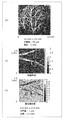
- FIG. 2 is a diagram showing an image of a mouse ear tissue visualized using a photoacoustic microscope.
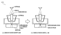
- FIG. 3 is a diagram showing the excitation light and the focus of the acoustic wave detector in the photoacoustic microscope of the comparative example.
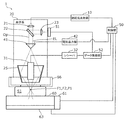
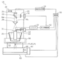
- FIG. 4 is a diagram showing the configuration of the photoacoustic microscope according to the first embodiment.
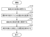
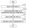
- FIG. 5 is a flowchart showing the acoustic wave measuring method according to the first embodiment.
- FIG. 6 is a diagram showing the configuration of the photoacoustic microscope according to the second embodiment.
- FIG. 1 is a schematic diagram showing a photoacoustic microscope of a comparative example.
- FIG. 2 is a diagram showing an image of a mouse ear tissue visualized using a photoacoustic microscope.
- FIG. 3 is a diagram showing the excitation light and the focus of the acous
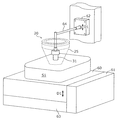
- FIG. 7 is a schematic diagram showing a first actuator and a second actuator of the photoacoustic microscope according to the second embodiment.
- FIG. 8 is a flowchart showing the acoustic wave measuring method according to the second embodiment.
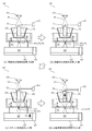
- FIG. 9 is a diagram showing the operation of the photoacoustic microscope according to the second embodiment.
- FIG. 1 is a schematic diagram showing photoacoustic microscopes 101 and 102 of a comparative example.
- a photoacoustic microscope is a device that visualizes the measurement target tissue by measuring the acoustic wave generated when the measurement target tissue that has absorbed the excitation light returns from the excited state to the steady state.
- FIG. 1A shows an acoustic resolution (AR) type photoacoustic microscope 101
- FIG. 1B shows an optical resolution (OR) type photoacoustic microscope 102.
- Each of these photoacoustic microscopes 101 and 102 includes an optical component that irradiates the measurement target with the excitation light, and an acoustic wave detection unit that detects the acoustic wave generated from the measurement target by irradiating the excitation light. ..
- FIG. 2 is a diagram showing an image of a mouse ear tissue visualized using the photoacoustic microscopes 101 and 102.
- FIG. 2A is an image in which the tissue structure is visualized using the AR-type photoacoustic microscope 101. As shown in FIG. 2A, by using the photoacoustic microscope 101, the tissue inside the living body can be visualized.
- FIG. 2B and 2C are images obtained by visualizing the tissue using the OR method photoacoustic microscope 102.
- FIG. 2B shows the tissue structure
- FIG. Shows the oxygen saturation (oxygen concentration) of blood in the blood vessel.
- the oxygen saturation of blood in a blood vessel can be determined by irradiating a tissue with excitation light having two kinds of wavelengths of 500 nm or more and 600 nm or less or 700 nm or more and 900 nm or less, as shown in (c) of FIG. To be visualized.
- the wavelength of the excitation light is changed according to the object to be visualized. For example, when visualizing a lipid component, a wavelength of 900 nm to 1400 nm is used, and when visualizing water, a wavelength of 1400 nm or more and 1500 nm or less is used. As described above, by changing the wavelength of the excitation light, it is possible to visualize various tissue structures and tissue states of the measurement target. However, if the wavelength of the excitation light is changed for each object to be visualized, the following problems occur.
- FIG. 3 is a diagram showing the excitation light and the focus of the acoustic wave detection unit in the photoacoustic microscope 101 of the comparative example.
- 3A is a diagram before changing the wavelength of the excitation light
- FIG. 3B is a diagram showing after changing the wavelength of the excitation light.
- the present invention provides a photoacoustic microscope capable of automatically adjusting the focus of the excitation light or the focus of the acoustic wave detection unit according to the changed wavelength even when the wavelength of the excitation light is changed. According to this photoacoustic microscope, it is possible to suppress deterioration of the quality of the image of the measurement target. Further, according to this photoacoustic microscope, the measurement target can be easily measured.
- FIG. 4 is a diagram showing the configuration of the photoacoustic microscope 1 according to the first embodiment.
- the photoacoustic microscope 1 is used, for example, when visualizing the tissue of the measurement target S1 such as biological tissues, blood vessel images, foods, industrial products such as resin materials and the like.
- the measurement target S1 is, for example, placed on the stage 60 and measured in a state of being in contact with the bottom surface of the water pool 66 (see FIG. 4 ).
- the photoacoustic microscope 1 includes an excitation light emitting unit 10, an optical system 20, a refractive index variable device 41, an acoustic wave detection unit 31, and a control unit 50.
- the photoacoustic microscope 1 also includes a power meter 51, a data acquisition unit 52, and a voltage output unit 42.
- the excitation light emitting unit 10 is a device that emits the excitation light EL, and is, for example, a laser device.
- the excitation light emitting unit 10 emits the excitation light EL having a wavelength of 400 nm or more and 2000 nm or less.
- the excitation light EL is pulsed light having a predetermined pulse width of, for example, 0.01 nsec or more and 10 nsec or less.
- a laser oscillator, a light emitting diode, or the like is used as the emission source of the excitation light emitting unit 10.
- the excitation light EL emitted from the excitation light emitting unit 10 is transmitted to the optical system 20 through an optical fiber or the like.
- the optical system 20 is a set of a plurality of optical elements for irradiating the measurement target S1 with the excitation light EL that has entered the optical system 20.
- the optical system 20 of the present embodiment includes optical components 21, 22, 23, a refractive index variable device 41, a prism 25, and a water pool 66 in which water is stored.
- the optical components 21 and 22, the variable refractive index device 41, the prism 25, and the water pool 66 are arranged on the optical path Op of the excitation light EL that connects the excitation light emitting unit 10 and the measurement target S1.
- the optical component 23 is arranged on the optical path of the excitation light EL that connects the optical component 22 and the power meter 51.
- the optical component 21 shapes the excitation light EL that has entered the optical component 21 in parallel and outputs it to the optical component 22.
- the optical component 21 is, for example, a collimator lens.
- the optical component 22 divides the excitation light EL incident on the optical component 22 into two, emits most of the excitation light EL to the refractive index variable device 41 side, and the remaining part of the excitation light EL to the optical component 23. Emit.
- the optical component 22 is, for example, a beam splitter.
- the optical component 23 collects a part of the incident excitation light EL and outputs it to the power meter 51.
- the optical component 23 is, for example, a condenser lens.
- the power meter 51 measures the power (intensity) of the incident excitation light EL and outputs the measurement result to the data acquisition unit (DAQ: Data Acquisition) 52. Since the excitation light EL has a property that the power varies depending on the wavelength, the data acquisition unit 52 corrects a signal related to the acoustic wave acquired via the acoustic wave detection unit 31 described later according to the measurement result of the power meter 51. Then, image information is formed.
- DAQ Data Acquisition
- the excitation light EL that has passed through the optical component 22 is applied to the measurement target S1 via the refractive index variable device 41, the prism 25, and the water pool 66.
- the variable refractive index device 41 is an optical element capable of changing the refractive index, and is, for example, a liquid lens.
- the refractive index variable device 41 is connected to the voltage output unit 42, and the refractive index changes according to the voltage applied from the voltage output unit 42.
- the voltage applied to the refractive index variable device 41 is a value determined according to the wavelength of the excitation light EL, and is controlled by the control unit 50 described later.
- the excitation light EL refracted by the refractive index variable device 41 is emitted to the prism 25 side.
- the excitation light EL emitted from the variable refractive index device 41 has a ring-shaped horizontal cross section.
- the prism 25 has an inverted truncated cone shape and also has a hollow region with a hollow inside.
- the prism 25 may be formed of a reflector such as a mirror.
- the prism 25 reflects the excitation light EL emitted from the variable refractive index device 41 and emits it to the water pool 66 side. Since the water pool 66 is made of a material that transmits the excitation light EL and the acoustic wave (ultrasonic wave), the excitation light EL emitted from the prism 25 passes through the water pool 66 and irradiates the measurement target S1. To be done.
- the focus F1 of the excitation light EL is set at the same height as the measurement point P1 of the measurement target S1.
- the tissue located at the measurement point P1 generates an acoustic wave when returning from the excited state to the steady state after absorbing the excitation light EL.
- the acoustic wave detection unit 31 is a probe that detects ultrasonic waves, and detects acoustic waves generated in the measurement target S1.
- the acoustic wave detection unit 31 is arranged above the measurement point P1 with a space from the measurement target S1. Specifically, the acoustic wave detection unit 31 is arranged in the hollow area of the prism 25.
- the focus F2 of the acoustic wave detector 31 is set at the same height as the measurement point P1.
- the acoustic wave detected by the acoustic wave detection unit 31 is converted into an electric signal according to the strength of the acoustic wave, amplified by the receiver 32, and output to the data acquisition unit 52.
- the data acquisition unit 52 corrects the acquired electric signal regarding the acoustic wave according to the measurement result of the power meter 51 to form image information.
- the control unit 50 instructs the excitation light emission unit 10 to change and emit the wavelength of the excitation light EL in order to visualize various tissue structures and tissue states of the measurement target S1.
- the control unit 50 controls the voltage of the voltage output unit 42 according to the changed wavelength of the excitation light EL, and controls the refractive index of the refractive index variable device 41.
- the control unit 50 is composed of a processor and a memory.
- the memory stores a calculation formula for obtaining the applied voltage of the voltage output unit 42 and the refractive index of the refractive index variable device 41 according to the wavelength of the excitation light EL, and a program for operating the processor.
- the control unit 50 changes the wavelength of the excitation light EL emitted from the excitation light emission unit 10, and controls the refractive index of the refractive index variable device 41 according to the changed wavelength of the excitation light EL. Specifically, when the wavelength of the excitation light EL is changed, the control unit 50 causes the focus F1 of the excitation light EL to approach the measurement point P1 before changing the wavelength, that is, the focus of the excitation light EL. The refractive index of the refractive index variable device 41 is controlled so that F1 approaches the focus F2 of the acoustic wave detection unit 31. With the control of the control unit 50, the photoacoustic microscope 1 can instantly and automatically perform focusing.
- control unit 50 changes so that the wavelength of the excitation light EL becomes longer, the control unit 50 changes so that the refractive index of the refractive index variable device 41 becomes larger, and when the wavelength of the excitation light EL becomes shorter. Is changed so that the refractive index of the refractive index variable device 41 becomes small.
- the photoacoustic microscope 1 can perform focusing in accordance with the change in the length of the wavelength of the excitation light EL.
- the photoacoustic microscope 1 includes a stage 60 on which the measurement target S1 is placed, a first actuator 61 that moves the stage 60 in a first direction D1 along the irradiation direction of the excitation light EL, and a vertical direction to the first direction D1.
- An actuator 63 that moves the stage 60 in various directions.
- Each actuator 61, 63 is provided with a position detector that detects the position coordinates of the stage 60.
- the first direction D1 is the vertical direction
- the direction perpendicular to the first direction D1 is the horizontal direction.
- the stage 60, the measurement target S1, and the water pool 66 are horizontally moved relative to the optical components 21 and 22, the refractive index variable device 41, the prism 25, and the acoustic wave detection unit 31 by driving the actuator 63. Further, the stage 60, the measurement target S1, and the water pool 66 are moved vertically relative to the optical components 21 and 22, the refractive index variable device 41, the prism 25, and the acoustic wave detection unit 31 by driving the actuator 61.
- the control unit 50 associates the image information formed by the data acquisition unit 52 with the position coordinates of the measurement point P1 of the measurement target S1 acquired from the actuators 61 and 63, and visualizes the tissue of the measurement target S1. Thereby, the control unit 50 can form a two-dimensional image and a three-dimensional image of the tissue of the measurement target S1.
- the photoacoustic microscope 1 has a variable index of refraction arranged on the optical path Op of the excitation light EL that emits the excitation light EL and the excitation light emission unit 10 and the measurement target S1.
- a control unit 50 that changes the wavelength and controls the refractive index of the refractive index variable device 41 according to the changed wavelength of the excitation light EL.
- control unit 50 controls the refractive index of the refractive index variable device 41 in accordance with the changed wavelength of the excitation light EL, so that the focus F1 of the excitation light EL and the focus F2 of the acoustic wave detection unit 31 are adjusted. Can be matched. According to this photoacoustic microscope 1, it is possible to suppress deterioration of the image quality of the measurement target S1. Further, the measurement target S1 can be easily measured.
- FIG. 5 is a flowchart showing the acoustic wave measuring method according to the first embodiment.
- the control unit 50 changes the wavelength of the excitation light EL (step S10). Specifically, the control unit 50 appropriately selects the wavelength of the excitation light EL from the range of 400 nm to 2000 nm depending on the object to be visualized. Then, the control unit 50 instructs the excitation light emitting unit 10 so that the wavelength of the excitation light EL becomes the selected wavelength.
- the refractive index of the refractive index variable device 41 is changed according to the changed wavelength of the excitation light EL (step S20). Specifically, the control unit 50 controls the voltage of the voltage output unit 42 according to the changed wavelength of the excitation light EL, and controls the refractive index of the refractive index variable device 41.
- control unit 50 may change the wavelength of the excitation light EL and the refractive index of the variable refractive index device 41 at the same time.
- the measurement light S1 is irradiated with the excitation light EL via the refractive index variable device 41 (step S30).
- the refractive index of the refractive index variable device 41 is changed according to the wavelength of the excitation light EL. Therefore, the position of the focal point F1 of the excitation light EL remains unchanged from the original position.
- the acoustic wave generated from the measurement target S1 irradiated with the excitation light EL is detected (step S40).
- the acoustic wave generated from the measurement target S1 can be measured in a state where the focus F1 of the excitation light EL and the focus F2 of the acoustic wave detection unit 31 are matched. As a result, it is possible to suppress deterioration of the image quality of the measurement target S1.
- the photoacoustic microscope 1 has a variable index of refraction arranged on the optical path Op of the excitation light EL that emits the excitation light EL and the excitation light emission unit 10 and the measurement target S1.
- a control unit 50 that changes the wavelength and controls the refractive index of the refractive index variable device 41 according to the changed wavelength of the excitation light EL.
- control unit 50 controls the refractive index of the refractive index variable device 41 in accordance with the changed wavelength of the excitation light EL, so that the focus F1 of the excitation light EL and the focus F2 of the acoustic wave detection unit 31 are adjusted. Can be matched. As a result, it is possible to suppress deterioration of the image quality of the measurement target S1.
- the control unit 50 may also control the refractive index of the refractive index variable device 41 so that the focus F1 of the excitation light EL approaches the focus F2 of the acoustic wave detection unit 31.
- the focus F1 of the excitation light EL and the focus F2 of the acoustic wave detection unit 31 can be matched. As a result, it is possible to suppress deterioration of the image quality of the measurement target S1.
- control unit 50 changes so that the wavelength of the excitation light EL becomes longer
- the control unit 50 changes so that the refractive index of the refractive index variable device 41 becomes larger, and when the wavelength of the excitation light EL becomes shorter.
- the refractive index variable device 41 may be modified so that the refractive index of the device 41 becomes small.
- variable refractive index device 41 may be an optical element whose refractive index changes according to the voltage applied to the variable refractive index device 41.
- variable refractive index device 41 may be a liquid lens.
- the refractive index of the refractive index variable device 41 can be easily changed. As a result, it is possible to easily suppress deterioration of the image quality of the measurement target S1.
- the control unit 50 may control the excitation light emitting unit 10 so that the wavelength of the excitation light EL is changed within the range of 400 nm or more and 2000 nm or less.
- the wavelength of the excitation light EL in the range of 400 nm or more and 2000 nm or less, various tissue structures and tissue states of the measurement target S1 can be visualized.
- the acoustic wave measuring method includes a step of changing the wavelength of the excitation light EL, and a refractive index variable device 41 arranged on the optical path Op of the excitation light EL according to the changed wavelength of the excitation light EL.
- the focus F1 of the excitation light EL and the focus of the acoustic wave at the time of detecting the acoustic wave are matched. You can As a result, it is possible to suppress deterioration of the image quality of the measurement target S1.
- FIG. 6 is a diagram showing the configuration of the photoacoustic microscope 1A according to the second embodiment.
- the photoacoustic microscope 1A includes an excitation light emitting unit 10, an optical system 20, an acoustic wave detection unit 31, and a control unit 50. Further, the photoacoustic microscope 1A includes a stage 60, a first actuator 61, and a second actuator 62.
- the excitation light emitting unit 10 is a device that emits the excitation light EL.
- the optical system 20 includes optical components 21, 22, 23, a lens 24, a prism 25, and a water pool 66.
- a lens 24 whose refractive index is not variable is arranged instead of the refractive index variable device 41 of the first embodiment.
- the excitation light EL that has passed through the optical component 22 is applied to the measurement target S1 via the lens 24, the prism 25, and the water pool 66.
- the focus F1 of the excitation light EL is set at the same height as the measurement point P1 of the measurement target S1.
- the tissue located at the measurement point P1 generates an acoustic wave when returning from the excited state to the steady state after absorbing the excitation light EL.
- the acoustic wave detection unit 31 detects the acoustic wave generated in the measurement target S1.
- the focus F2 of the acoustic wave detector 31 is set at the same height as the measurement point P1.
- the acoustic wave detection unit 31 is connected to the second actuator 62.
- FIG. 7 is a schematic diagram showing the first actuator 61 and the second actuator 62 of the photoacoustic microscope 1A.
- the second actuator 62 is connected to the acoustic wave detection unit 31 via the L-shaped connecting member 64, and moves the acoustic wave detection unit 31 in the first direction D1 along the irradiation direction of the excitation light EL.
- the first direction D1 is the height direction.
- the height position of the acoustic wave detection unit 31 is determined by driving the second actuator 62, and the driving of the second actuator 62 is controlled by the control unit 50.
- the second actuator 62 is, for example, a linear actuator that is driven by an ultrasonic motor.
- the first actuator 61 is connected to the stage 60 on which the measurement target S1 is placed, and moves the stage 60 in the first direction D1.
- the first actuator 61 and the second actuator 62 move in the same direction.
- the height position of the stage 60 is determined by driving the first actuator 61, and the driving of the first actuator 61 is controlled by the controller 50.
- the first actuator 61 is, for example, a linear actuator that is driven by a piezoelectric element or a uniaxial robot.
- the control unit 50 instructs the excitation light emission unit 10 to change and emit the wavelength of the excitation light EL in order to visualize various tissue structures and tissue states of the measurement target S1. Further, the control unit 50 controls the drive of each of the first actuator 61 and the second actuator 62 according to the changed wavelength of the excitation light EL.
- the values of the wavelength of the excitation light EL, the height position of the acoustic wave detection unit 31, and the height position of the stage 60 are associated and stored in advance in the memory of the control unit 50. Further, the memory stores a calculation formula for obtaining the height position of the acoustic wave detection unit 31 and the height position of the stage 60 according to the wavelength of the excitation light EL, and a program for operating the processor.
- the control unit 50 changes the wavelength of the excitation light EL emitted from the excitation light emission unit 10, and drives the first actuator 61 and the second actuator 62 according to the changed wavelength of the excitation light EL.
- Control Specifically, when the wavelength of the excitation light EL is changed, the control unit 50 drives the first actuator 61 so that the measurement point P1 of the measurement target S1 to be measured approaches the focus F1 of the excitation light EL. Then, the driving of the second actuator 62 is controlled so that the focus F2 of the acoustic wave detection unit 31 approaches the measurement point P1.
- the photoacoustic microscope 1A can automatically perform focusing.
- control unit 50 controls the drive of the first actuator 61 so that the distance between the optical system 20 and the measurement target S1 becomes large when the wavelength of the excitation light EL is changed to be long, and follows it. Then, the distance between the acoustic wave detection unit 31 and the measurement target S1 is adjusted using the second actuator 62. Further, the control unit 50 controls the drive of the first actuator 61 so that the distance between the optical system 20 and the measurement target S1 becomes small when the wavelength of the excitation light EL is changed to be short, and follows it. Then, the distance between the acoustic wave detection unit 31 and the measurement target S1 is adjusted using the second actuator 62.
- the photoacoustic microscope 1A can perform focusing according to the change in the length of the wavelength of the excitation light EL.
- the present invention is not limited to this.
- the acoustic wave detecting unit 31 is connected to the first actuator 61 via a connecting member different from the connecting member 64, the acoustic wave detecting unit 31 and the stage 60 are moved using only the first actuator 61. You may let me.
- the photoacoustic microscope 1A includes an excitation light emitting unit 10 that emits the excitation light EL, and an optical system 20 arranged on the optical path of the excitation light EL that connects the excitation light emitting unit 10 and the measurement target S1.
- the acoustic wave detection unit 31 that detects the acoustic wave generated from the measurement target S1 irradiated with the excitation light EL via the optical system 20, and the measurement target S1 and the acoustic wave detection unit 31 are arranged in the irradiation direction of the excitation light EL.
- At least one actuator (for example, actuators 61 and 62) that moves in the first direction D1 and the wavelength of the excitation light EL emitted from the excitation light emitting unit 10 are changed, and the actuator 61 is changed according to the changed wavelength of the excitation light EL. , 62 for controlling the driving of
- control unit 50 controls the driving of the actuators 61 and 62 according to the changed wavelength of the excitation light EL, so that the focus F1 of the excitation light EL and the focus F2 of the acoustic wave detection unit 31 are aligned with each other.
- FIG. 8 is a flowchart showing an acoustic wave measuring method according to the second embodiment.
- FIG. 9 is a diagram showing the operation of the photoacoustic microscope 1A.
- 9A is a diagram showing a state before the wavelength of the excitation light EL is changed
- FIG. 9B is a diagram showing a state after the wavelength of the excitation light EL is changed
- FIG. 9C is a diagram showing a state after the stage 60 is moved in the first direction D1 using the first actuator 61
- FIG. 9D is an acoustic wave detection unit using the second actuator 62. It is a figure which shows after moving 31 in the 1st direction D1.
- the control unit 50 changes the wavelength of the excitation light EL (step S10). As shown in (a) of FIG. 9, before the wavelength of the excitation light EL is changed, the focus F1 of the excitation light EL, the focus F2 of the acoustic wave detection unit 31, and the measurement point P1 match each other. (B), after the wavelength of the excitation light EL is changed, the focus F1 of the excitation light EL is deviated from the focus F2 of the acoustic wave detection unit 31 and the measurement point P1.
- the distance between the prism 25, which is one of the optical systems 20, and the measurement target S1 is the distance L1
- step S20A the distance between the optical system 20 and the measurement target S1 and the distance between the acoustic wave detection unit 31 and the measurement target S1 are changed according to the changed wavelength of the excitation light EL.
- the distance between the optical system 20 and the measurement target S1 is changed to the distance L11 (L11>L1) using the first actuator 61, and the measurement point P1 is changed.
- the focus F1 of the excitation light EL is brought closer.
- the first actuator 61 by driving the first actuator 61 to change the height position of the measurement target S1, the distance between the acoustic wave detection unit 31 and the measurement target S1 is changed to the distance L21 (L21>L2), and the acoustic The focus F2 of the wave detection unit 31 is deviated from the measurement point P1 after the movement. Therefore, as shown in (d) of FIG.
- the focal point F2 of is close to the measurement point P1.
- the focus F1 of the excitation light EL, the focus F2 of the acoustic wave detection unit 31, and the measurement point P1 are matched.
- the present invention is not limited to this.
- the first actuator 61 may be driven after driving the second actuator 62, or the first actuator 61 and the second actuator 62 may be simultaneously driven.
- the control unit 50 simultaneously changes the wavelength of the excitation light EL, changes the distance between the optical system 20 and the measurement target S1, and changes the distance between the acoustic wave detection unit 31 and the measurement target S1. Good.
- the measurement light S1 is irradiated with the excitation light EL via the optical system 20 (step S30).
- the acoustic wave detection unit 31 is used to detect the acoustic wave generated from the measurement target S1 (step S40).
- the acoustic wave generated from the measurement target S1 can be measured in a state where the focus F1 of the excitation light EL and the focus F2 of the acoustic wave detecting unit 31 are aligned with each other. As a result, it is possible to suppress deterioration of the image quality of the measurement target S1.
- the photoacoustic microscope 1A includes an excitation light emitting unit 10 that emits the excitation light EL, and an optical system 20 arranged on the optical path Op of the excitation light EL that connects the excitation light emitting unit 10 and the measurement target S1. And the acoustic wave detection unit 31 that detects the acoustic wave generated from the measurement target S1 irradiated with the excitation light EL via the optical system 20, and the measurement target S1 and the acoustic wave detection unit 31 in the irradiation direction of the excitation light EL.
- At least one actuator (for example, the actuators 61 and 62) that moves in the first direction D1 along with the wavelength of the excitation light EL emitted from the excitation light emitting unit 10, and the actuator according to the changed wavelength of the excitation light EL.
- a control unit 50 for controlling the driving of 61 and 62.
- control unit 50 controls the driving of the actuators 61 and 62 according to the changed wavelength of the excitation light EL, so that the focus F1 of the excitation light EL and the focus F2 of the acoustic wave detection unit 31 are aligned with each other. You can As a result, it is possible to suppress deterioration of the image quality of the measurement target S1.
- At least one actuator includes a first actuator 61 that moves the measurement target S1 in the first direction D1 and a second actuator 62 that moves the acoustic wave detection unit 31 in the first direction D1.
- the unit 50 may control the drive of each of the first actuator 61 and the second actuator 62 according to the wavelength of the excitation light EL.
- the focus F1 of the excitation light EL and the focus F2 of the acoustic wave detection unit 31 can be easily aligned. As a result, it is possible to easily suppress deterioration of the image quality of the measurement target S1.
- control unit 50 controls the drive of the first actuator 61 so that the measurement point P1 of the measurement target S1 to be measured approaches the focus F1 of the excitation light EL, and the focus F2 of the acoustic wave detection unit 31.
- the driving of the second actuator 62 may be controlled so that the point P approaches the measurement point P1.
- the focus F1 of the excitation light EL and the focus F2 of the acoustic wave detection unit 31 can be aligned. As a result, it is possible to suppress deterioration of the image quality of the measurement target S1.
- control unit 50 controls the drive of the first actuator 61 so that the distance between the optical system 20 and the measurement target S1 becomes large when the wavelength of the excitation light EL is changed to be long, and the excitation light EL is controlled.
- the driving of the first actuator 61 may be controlled so that the distance between the optical system 20 and the measurement target S1 becomes smaller.
- the control unit 50 may also control the excitation light emitting unit 10 so that the wavelength of the excitation light EL is changed in the range of 400 nm to 2000 nm.
- the wavelength of the excitation light EL in the range of 400 nm or more and 2000 nm or less, various tissue structures and tissue states of the measurement target S1 can be visualized.
- the acoustic wave measuring method includes a step of changing the wavelength of the excitation light EL, and a measurement with the optical system 20 arranged on the optical path Op of the excitation light EL according to the changed wavelength of the excitation light EL.
- a step of changing the distance between the measurement target S1 and the distance between the measurement target S1 and the acoustic wave detection unit 31 that is spaced apart from the measurement target S1, and the excitation light EL is measured through the optical system 20.
- the focus F1 of the excitation light EL can be obtained. It is possible to adjust the focus of the acoustic wave when detecting the acoustic wave. As a result, it is possible to suppress deterioration of the image quality of the measurement target S1.
- the AR-type photoacoustic microscope has been described as an example, but the present invention is not limited to this, and the photoacoustic microscope is an OR-type photoacoustic microscope including an optical component having an acoustic lens and an oil layer. Good.
- the focus F2 of the acoustic wave detection unit 31 is set at a position having a height determined according to the measurement point P1 of the measurement target S1, but the positioning of the focus F2 is not limited to manual work, and photoacoustic is performed. It may be performed by a camera or a sensor included in the microscope.
- a marker may be provided at a predetermined position of the measurement target S1, the marker may be detected by a camera, and the height position of the focus F2 may be calibrated.
- the photoacoustic microscope according to the present invention is used when visualizing a tissue to be measured such as a biological tissue, a blood vessel image, food, an industrial product such as a resin material, or the like.
- Photoacoustic microscope 10 Excitation light emitting part 20 Optical systems 21, 22, 23 Optical parts 24 Lens 25 Prism 31 Acoustic wave detecting part 32 Receiver 41 Refractive index variable device 42 Voltage output part 50 Control part 51 Power meter 52 Data acquisition Part 60 Stage 61 First Actuator 62 Second Actuator 63 Actuator 64 Connecting Member 66 Water Pool D1 First Direction EL Excitation Light F1 Focus of Excitation Light F2 Focuses of Acoustic Wave Detector L1, L2, L11, L21, L22 Distance Op optical path P1 measurement point S1 measurement target
Landscapes
- Health & Medical Sciences (AREA)
- Life Sciences & Earth Sciences (AREA)
- Pathology (AREA)
- General Health & Medical Sciences (AREA)
- Physics & Mathematics (AREA)
- Surgery (AREA)
- Biophysics (AREA)
- Engineering & Computer Science (AREA)
- Biomedical Technology (AREA)
- Heart & Thoracic Surgery (AREA)
- Medical Informatics (AREA)
- Molecular Biology (AREA)
- Nuclear Medicine, Radiotherapy & Molecular Imaging (AREA)
- Animal Behavior & Ethology (AREA)
- Radiology & Medical Imaging (AREA)
- Public Health (AREA)
- Veterinary Medicine (AREA)
- Chemical & Material Sciences (AREA)
- Analytical Chemistry (AREA)
- Biochemistry (AREA)
- General Physics & Mathematics (AREA)
- Immunology (AREA)
- Investigating Or Analyzing Materials By The Use Of Ultrasonic Waves (AREA)
- Ultra Sonic Daignosis Equipment (AREA)
- Investigating Or Analysing Materials By Optical Means (AREA)
Abstract
光音響顕微鏡(1)は、励起光(EL)を出射する励起光出射部(10)と、励起光出射部(10)および測定対象(S1)を結ぶ励起光(EL)の光路(Op)上に配置された屈折率可変デバイス(41)と、屈折率可変デバイス(41)を介して励起光(EL)が照射された測定対象(S1)から発生した音響波を検知する音響波検知部(31)と、励起光出射部(10)から出射される励起光(EL)の波長を変更し、変更した励起光(EL)の波長に応じて屈折率可変デバイス(41)の屈折率を制御する制御部(50)とを備える。
Description
本発明は、音響波を測定する光音響顕微鏡および音響波測定方法に関する。
測定対象に励起光が照射されることで、測定対象から音響波が発生する。この音響波を測定する装置として、光音響顕微鏡が知られている(例えば、特許文献1参照)。
特許文献1には、測定対象から発生した音響波を検知する音響波検知部と、測定対象を撮像するカメラと、音響波検知部およびカメラを測定対象に対して走査する走査機構とを備える光音響顕微鏡が開示されている。この光音響顕微鏡では、音響波検知部およびカメラの位置関係を維持したまま水平方向に走査することで、測定位置および測定範囲を正確に定めている。
しかしながら、特許文献1に開示された光音響顕微鏡では、励起光の波長を変更した場合に励起光の焦点の位置が変わり、音響波検知部を介して取得する測定対象の画像の質が低下するという問題がある。
本発明は、上述した課題を解決するものであり、励起光の波長を変更した場合に、測定対象の画像の質が低下することを抑制することができる光音響顕微鏡等を提供することを目的とする。
本発明の一態様に係る光音響顕微鏡は、励起光を出射する励起光出射部と、前記励起光出射部および測定対象を結ぶ前記励起光の光路上に配置された屈折率可変デバイスと、前記屈折率可変デバイスを介して前記励起光が照射された前記測定対象から発生した音響波を検知する音響波検知部と、前記励起光出射部から出射される前記励起光の波長を変更し、変更した前記励起光の波長に応じて前記屈折率可変デバイスの屈折率を制御する制御部とを備える。
本発明の一態様に係る光音響顕微鏡は、励起光を出射する励起光出射部と、前記励起光出射部および測定対象を結ぶ前記励起光の光路上に配置された光学系と、前記光学系を介して前記励起光が照射された前記測定対象から発生した音響波を検知する音響波検知部と、前記測定対象および前記音響波検知部を前記励起光の照射方向に沿う第1方向に移動させる少なくとも1つのアクチュエータと、前記励起光出射部から出射される前記励起光の波長を変更し、変更した前記励起光の波長に応じて前記アクチュエータの駆動を制御する制御部とを備える。
本発明の一態様に係る音響波測定方法は、励起光の波長を変更するステップと、変更した前記励起光の波長に応じて、前記励起光の光路上に配置された屈折率可変デバイスの屈折率を変更するステップと、前記屈折率可変デバイスを介して前記励起光を測定対象に照射するステップと、前記励起光が照射された前記測定対象から発生した音響波を検知するステップとを含む。
本発明の一態様に係る音響波測定方法は、励起光の波長を変更するステップと、変更した前記励起光の波長に応じて、励起光の光路上に配置された光学系と測定対象との距離および前記測定対象に対して間隔をあけて配置された音響波検知部と前記測定対象との距離を変更するステップと、前記光学系を介して前記励起光を前記測定対象に照射するステップと、前記励起光が照射された前記測定対象から発生した音響波を、前記音響波検知部を用いて検知するステップとを含む。
本発明の光音響顕微鏡等によれば、励起光の波長を変更した場合に、測定対象の画像の質が低下することを抑制することができる。
(本発明に至る経緯)
まず、本発明に至る経緯について、図1~図3を参照しながら説明する。
まず、本発明に至る経緯について、図1~図3を参照しながら説明する。
図1は、比較例の光音響顕微鏡101、102を示す模式図である。
光音響顕微鏡は、励起光を吸収した測定対象の組織が励起状態から定常状態に戻る際に発生する音響波を測定することで、測定対象の組織を可視化する装置である。図1の(a)には、Acoustic Resolution(AR)方式の光音響顕微鏡101が示され、図1の(b)には、Optical Resolution(OR)方式の光音響顕微鏡102が示されている。これらの光音響顕微鏡101、102は、励起光を測定対象に向けて照射する光学部品と、励起光を照射することで測定対象から発生した音響波を検知する音響波検知部とを備えている。
図2は、光音響顕微鏡101、102を用いて可視化したマウスの耳の組織の画像を示す図である。図2の(a)は、AR方式の光音響顕微鏡101を用いて組織構造を可視化した画像である。図2の(a)に示すように、光音響顕微鏡101を用いることで、生体内部の組織を可視化することができる。
図2の(b)および(c)は、OR方式の光音響顕微鏡102を用いて組織を可視化した画像であり、図2の(b)には組織構造が示され、図2の(c)には血管中の血液の酸素飽和度(酸素濃度)が示されている。例えば、血管中の血液の酸素飽和度は、500nm以上600nm以下または700nm以上900nm以下の波長のうち2種類の波長の励起光を組織に照射することで、図2の(c)に示すように可視化される。
可視化すべき対象によって吸収しやすい波長が異なるため、光音響顕微鏡では、可視化すべき対象に合わせて励起光の波長を変更する。例えば、脂質成分を可視化する場合は、900nm~1400nmの波長が用いられ、水分を可視化する場合は1400nm以上1500nm以下の波長が用いられる。このように、励起光の波長を変更することで、測定対象の様々な組織構造および組織の状態を可視化することが可能である。しかしながら、可視化する対象ごとに励起光の波長を変更すると、以下に示す問題が起きる。
図3は、比較例の光音響顕微鏡101における励起光および音響波検知部の焦点を示す図である。図3の(a)は励起光の波長を変更する前、(b)は励起光の波長を変更した後を示す図である。これらの図に示すように、励起光の波長を変更すると、光学部品を介して測定対象に照射される励起光の焦点の位置がずれ、励起光の焦点と音響波検知部の焦点とが合わなくなる。そのため、音響波検知部を介して取得する画像の質が低下するという問題がある。
それに対し、励起光の波長を変更するごとに、励起光の焦点と音響波検知部の焦点とを手作業で合わせることも可能である。しかしながら、励起光の波長を変更するごとに、音響波検知部の焦点を励起光の焦点に合わせることは、多大な労力と時間を必要とする。
また、励起光の波長を連続的に変更しながら音響波を測定し、測定対象を多面的に解析する構想もあるが、上記のように手作業で焦点を合わせる方法では、そのような構想を高速に実現することが困難である。
本発明は、励起光の波長を変更した場合であっても、変更した波長に応じて、励起光の焦点または音響波検知部の焦点を自動で合わせることができる光音響顕微鏡を提供する。この光音響顕微鏡によれば、測定対象の画像の質が低下することを抑制することができる。また、この光音響顕微鏡によれば、測定対象を簡易に測定することができる。
以下、本発明の実施の形態について、図面を用いて詳細に説明する。なお、以下で説明する実施の形態は、いずれも本発明の好ましい一具体例を示すものである。以下の実施の形態で示される数値、形状、材料、構成要素、構成要素の配置位置及び接続形態、ステップ、ステップの順序などは、一例であり、本発明を限定する主旨ではない。本発明は、請求の範囲によって特定される。よって、以下の実施の形態における構成要素のうち、独立請求項に記載されていない構成要素については、任意の構成要素として説明される。また、各図において、実質的に同一の構成に対しては同一の符号を付しており、重複する説明は、省略または簡略化する。
(実施の形態1)
[1-1.光音響顕微鏡の構成]
本実施の形態に係る光音響顕微鏡について、図4を参照しながら説明する。
[1-1.光音響顕微鏡の構成]
本実施の形態に係る光音響顕微鏡について、図4を参照しながら説明する。
図4は、実施の形態1に係る光音響顕微鏡1の構成を示す図である。
光音響顕微鏡1は、例えば、生体組織、血管像、食品、樹脂材料などの工業製品などの測定対象S1の組織を可視化する際に利用される。測定対象S1は、例えば、ステージ60上に配置され、ウォータプール66の底面に接した状態で測定される(図4参照)。
光音響顕微鏡1は、励起光出射部10と、光学系20と、屈折率可変デバイス41と、音響波検知部31と、制御部50とを備えている。また、光音響顕微鏡1は、パワーメータ51、データ集録部52および電圧出力部42を備えている。
励起光出射部10は、励起光ELを出射する装置であり、例えばレーザ装置である。励起光出射部10は、400nm以上2000nm以下の波長を有する励起光ELを出射する。励起光ELは、例えば0.01nsec以上10nsec以下の所定のパルス幅を有するパルス光である。励起光出射部10の出射源としては、レーザ発振器または発光ダイオードなどが用いられる。励起光出射部10から出射された励起光ELは、光ファイバーなどを通って光学系20まで伝送される。
光学系20は、光学系20に入射した励起光ELを測定対象S1に照射するための複数の光学素子の集合物である。本実施の形態の光学系20は、光学部品21、22、23と、屈折率可変デバイス41と、プリズム25と、水が蓄えられたウォータプール66とを備えている。
光学部品21、22、屈折率可変デバイス41、プリズム25およびウォータプール66は、励起光出射部10と測定対象S1とを結ぶ励起光ELの光路Op上に配置されている。光学部品23は、光学部品22とパワーメータ51とを結ぶ励起光ELの光路上に配置されている。
光学部品21は、光学部品21に入射した励起光ELを平行に整形して光学部品22に出射する。光学部品21は、例えばコリメートレンズである。
光学部品22は、光学部品22に入射した励起光ELを2つに分け、大部分の励起光ELを屈折率可変デバイス41側に出射し、残りの一部の励起光ELを光学部品23に出射する。光学部品22は、例えばビームスプリッタである。
光学部品23は、入射した一部の励起光ELを集光し、パワーメータ51に出射する。光学部品23は、例えば集光レンズである。
パワーメータ51は、入射した励起光ELのパワー(強度)を計測し、計測結果をデータ集録部(DAQ:Data AcQuisition)52に出力する。励起光ELは、波長によってパワーが異なるという性質を有するため、データ集録部52は、後述する音響波検知部31を介して取得した音響波に関する信号を、パワーメータ51の計測結果に応じて補正して画像情報を形成する。
光学部品22を通過した励起光ELは、屈折率可変デバイス41、プリズム25およびウォータプール66を介して測定対象S1に照射される。
屈折率可変デバイス41は、屈折率を変えることができる光学素子であり、例えば液体レンズである。屈折率可変デバイス41は、電圧出力部42に接続され、電圧出力部42から印加される電圧に応じて屈折率が変化する。屈折率可変デバイス41に印加される電圧は、励起光ELの波長に応じて決められた値であり、後述する制御部50によって制御される。屈折率可変デバイス41によって屈折させられた励起光ELは、プリズム25側に出射される。なお、屈折率可変デバイス41から出射される励起光ELは、水平断面がリング状の形状を有している。
プリズム25は、逆円錐台状の形状を有し、また、内部が中空となった中空領域を有している。プリズム25は、ミラーのような反射体で形成されていてもよい。プリズム25は、屈折率可変デバイス41から出射された励起光ELを反射して、ウォータプール66側に出射する。ウォータプール66は、励起光ELおよび音響波(超音波)を透過する材料によって構成されているので、プリズム25から出射された励起光ELは、ウォータプール66を透過して、測定対象S1に照射される。
図4に示すように、励起光ELの焦点F1は、測定対象S1の測定点P1と同じ高さの位置に設定される。測定点P1に位置する組織は、励起光ELを吸収した後、励起状態から定常状態に戻る際に音響波を発生する。
音響波検知部31は、超音波を検知する探触子であり、測定対象S1にて発生した音響波を検知する。音響波検知部31は、測定点P1の上方において測定対象S1に対して間隔をあけて配置される。具体的には、音響波検知部31は、プリズム25の中空領域に配置される。音響波検知部31の焦点F2は、測定点P1と同じ高さの位置に設定される。
音響波検知部31にて検知された音響波は、音響波の強さに応じた電気信号に変換され、レシーバ32によって増幅され、データ集録部52に出力される。データ集録部52は、取得した音響波に関する電気信号を、パワーメータ51の計測結果に応じて補正して画像情報を形成する。
制御部50は、測定対象S1の様々な組織構造および組織の状態を可視化するため、励起光ELの波長を変更して出射するように励起光出射部10に指示する。また、制御部50は、変更した励起光ELの波長に応じて、電圧出力部42の電圧を制御し、屈折率可変デバイス41の屈折率を制御する。
制御部50は、プロセッサおよびメモリなどによって構成されている。メモリには、励起光ELの波長、電圧出力部42の印加電圧、および、屈折率可変デバイス41の屈折率に関する値が、予め関連づけられて記憶されている。また、メモリには、励起光ELの波長に応じて電圧出力部42の印加電圧および屈折率可変デバイス41の屈折率を求める計算式、および、プロセッサを作動するプログラムが格納されている。
このように制御部50は、励起光出射部10から出射される励起光ELの波長を変更し、変更した励起光ELの波長に応じて屈折率可変デバイス41の屈折率を制御する。具体的には、制御部50は、励起光ELの波長を変更した場合に、励起光ELの焦点F1が、波長を変更する前の測定点P1に近づくように、すなわち、励起光ELの焦点F1が音響波検知部31の焦点F2に近づくように、屈折率可変デバイス41の屈折率を制御する。この制御部50の制御により、光音響顕微鏡1では、瞬時に自動で焦点合わせが可能となる。
また、制御部50は、励起光ELの波長が長くなるように変更した場合に屈折率可変デバイス41の屈折率が大きくなるように変更し、励起光ELの波長が短くなるように変更した場合に屈折率可変デバイス41の屈折率が小さくなるように変更する。この制御部50の制御により、光音響顕微鏡1では、励起光ELの波長の長短の変更に応じて焦点合わせが可能となる。
また、光音響顕微鏡1は、測定対象S1を載置するステージ60と、励起光ELの照射方向に沿う第1方向D1にステージ60を移動させる第1のアクチュエータ61と、第1方向D1に垂直な方向にステージ60を移動させるアクチュエータ63とを備えている。各アクチュエータ61、63には、ステージ60の位置座標を検出する位置検出器が設けられている。本実施の形態では、第1方向D1は鉛直方向であり、第1方向D1に垂直な方向は水平方向である。ステージ60、測定対象S1およびウォータプール66は、アクチュエータ63の駆動によって、光学部品21、22、屈折率可変デバイス41、プリズム25および音響波検知部31に対して、相対的に水平移動させられる。また、ステージ60、測定対象S1およびウォータプール66は、アクチュエータ61の駆動によって、光学部品21、22、屈折率可変デバイス41、プリズム25および音響波検知部31に対して、相対的に垂直移動させられる。
制御部50は、データ集録部52にて形成した画像情報と、各アクチュエータ61、63から取得した測定対象S1の測定点P1の位置座標とを対応づけて、測定対象S1の組織を可視化する。これにより、制御部50は、測定対象S1の組織の2次元画像および3次元画像を形成することができる。
本実施の形態に係る光音響顕微鏡1は、励起光ELを出射する励起光出射部10と、励起光出射部10および測定対象S1を結ぶ励起光ELの光路Op上に配置された屈折率可変デバイス41と、屈折率可変デバイス41を介して励起光ELが照射された測定対象S1から発生した音響波を検知する音響波検知部31と、励起光出射部10から出射される励起光ELの波長を変更し、変更した励起光ELの波長に応じて屈折率可変デバイス41の屈折率を制御する制御部50とを備える。
このように、制御部50が、変更した励起光ELの波長に応じて屈折率可変デバイス41の屈折率を制御することで、励起光ELの焦点F1と音響波検知部31の焦点F2とを合わせることができる。この光音響顕微鏡1によれば、測定対象S1の画像の質が低下することを抑制することができる。また、測定対象S1を簡易に測定することができる。
[1-2.音響波測定方法]
次に、光音響顕微鏡1を用いた音響波測定方法について、図5を参照しながら説明する。
次に、光音響顕微鏡1を用いた音響波測定方法について、図5を参照しながら説明する。
図5は、実施の形態1に係る音響波測定方法を示すフローチャートである。
まず、制御部50は、励起光ELの波長を変更する(ステップS10)。具体的には、制御部50は、可視化すべき対象に応じて、励起光ELの波長を400nm以上2000nm以下の範囲から適宜選択する。そして制御部50は、励起光ELの波長が、選択した波長となるように励起光出射部10に指示する。
次に、変更した励起光ELの波長に応じて、屈折率可変デバイス41の屈折率を変更する(ステップS20)。具体的には、制御部50が、変更した励起光ELの波長に応じて、電圧出力部42の電圧を制御し、屈折率可変デバイス41の屈折率を制御する。
なお、上記では励起光ELの波長を変更した後に、屈折率可変デバイス41の屈折率を変更する例を示したが、それに限られない。例えば、制御部50は、励起光ELの波長の変更と屈折率可変デバイス41の屈折率の変更とを同時に行ってもよい。
次に、屈折率可変デバイス41を介して励起光ELを測定対象S1に照射する(ステップS30)。例えば、励起光ELの波長が変更されると励起光ELの焦点F1の位置が変わってしまうが、本実施の形態では、励起光ELの波長に応じて屈折率可変デバイス41の屈折率を変更するので、励起光ELの焦点F1の位置は元の位置のまま変更されない。
次に、音響波検知部31を用いて、励起光ELが照射された測定対象S1から発生した音響波を検知する(ステップS40)。本実施の形態の音響波測定方法では、励起光ELの焦点F1と音響波検知部31の焦点F2とを一致させた状態で、測定対象S1から発生した音響波を測定することができる。これにより、測定対象S1の画像の質が低下することを抑制することができる。
[1-3.効果等]
本実施の形態に係る光音響顕微鏡1は、励起光ELを出射する励起光出射部10と、励起光出射部10および測定対象S1を結ぶ励起光ELの光路Op上に配置された屈折率可変デバイス41と、屈折率可変デバイス41を介して励起光ELが照射された測定対象S1から発生した音響波を検知する音響波検知部31と、励起光出射部10から出射される励起光ELの波長を変更し、変更した励起光ELの波長に応じて屈折率可変デバイス41の屈折率を制御する制御部50とを備える。
本実施の形態に係る光音響顕微鏡1は、励起光ELを出射する励起光出射部10と、励起光出射部10および測定対象S1を結ぶ励起光ELの光路Op上に配置された屈折率可変デバイス41と、屈折率可変デバイス41を介して励起光ELが照射された測定対象S1から発生した音響波を検知する音響波検知部31と、励起光出射部10から出射される励起光ELの波長を変更し、変更した励起光ELの波長に応じて屈折率可変デバイス41の屈折率を制御する制御部50とを備える。
このように、制御部50が、変更した励起光ELの波長に応じて屈折率可変デバイス41の屈折率を制御することで、励起光ELの焦点F1と音響波検知部31の焦点F2とを合わせることができる。これにより、測定対象S1の画像の質が低下することを抑制することができる。
また、制御部50は、励起光ELの焦点F1が音響波検知部31の焦点F2に近づくように、屈折率可変デバイス41の屈折率を制御してもよい。
この構成によれば、励起光ELの焦点F1と音響波検知部31の焦点F2とを合わせることができる。これにより、測定対象S1の画像の質が低下することを抑制することができる。
また、制御部50は、励起光ELの波長が長くなるように変更した場合に屈折率可変デバイス41の屈折率が大きくなるように変更し、励起光ELの波長が短くなるように変更した場合に屈折率可変デバイス41の屈折率が小さくなるように変更してもよい。
この構成によれば、励起光ELの波長の長短の変更に応じて焦点合わせをすることが可能となる。これにより、測定対象S1の画像の質が低下することを抑制することができる。
また、屈折率可変デバイス41は、屈折率可変デバイス41に印加される電圧によって屈折率が変わる光学素子であってもよい。
この構成によれば、屈折率可変デバイス41に印加される電圧を変えることによって焦点合わせをすることが可能となる。これにより、測定対象S1の画像の質が低下することを抑制することができる。
また、屈折率可変デバイス41は、液体レンズであってもよい。
この構成によれば、屈折率可変デバイス41の屈折率を簡易に変更することができる。これにより、測定対象S1の画像の質が低下することを簡易に抑制することができる。
また、制御部50は、400nm以上2000nm以下の範囲で励起光ELの波長が変更されるように、励起光出射部10を制御してもよい。
このように、400nm以上2000nm以下の範囲の励起光ELの波長を用いることで、測定対象S1の様々な組織構造および組織の状態を可視化することができる。
本実施の形態に係る音響波測定方法は、励起光ELの波長を変更するステップと、変更した励起光ELの波長に応じて、励起光ELの光路Op上に配置された屈折率可変デバイス41の屈折率を変更するステップと、屈折率可変デバイス41を介して励起光ELを測定対象S1に照射するステップと、励起光ELが照射された測定対象S1から発生した音響波を検知するステップとを含む。
このように、変更した励起光ELの波長に応じて屈折率可変デバイス41の屈折率を変更することで、励起光ELの焦点F1と音響波を検知する際の音響波の焦点とを合わせることができる。これにより、測定対象S1の画像の質が低下することを抑制することができる。
(実施の形態2)
[2-1.光音響顕微鏡の構成]
実施の形態2に係る光音響顕微鏡について、図6を参照しながら説明する。実施の形態2では、屈折率可変デバイスを用いるのでなく、ステージ60および音響波検知部31の高さ位置を変えることで焦点合わせを行う例について説明する。なお、実施の形態2では、実施の形態1と同じ構成要素について、説明を省略する場合がある。
[2-1.光音響顕微鏡の構成]
実施の形態2に係る光音響顕微鏡について、図6を参照しながら説明する。実施の形態2では、屈折率可変デバイスを用いるのでなく、ステージ60および音響波検知部31の高さ位置を変えることで焦点合わせを行う例について説明する。なお、実施の形態2では、実施の形態1と同じ構成要素について、説明を省略する場合がある。
図6は、実施の形態2に係る光音響顕微鏡1Aの構成を示す図である。図6に示すように、光音響顕微鏡1Aは、励起光出射部10と、光学系20と、音響波検知部31と、制御部50とを備えている。また、光音響顕微鏡1Aは、ステージ60と、第1のアクチュエータ61と、第2のアクチュエータ62とを備えている。
励起光出射部10は、励起光ELを出射する装置である。
光学系20は、光学部品21、22、23と、レンズ24と、プリズム25と、ウォータプール66とを備えている。実施の形態2では、実施の形態1の屈折率可変デバイス41の代わりに、屈折率が可変でないレンズ24が配置されている。
光学部品22を通過した励起光ELは、レンズ24、プリズム25およびウォータプール66を介して測定対象S1に照射される。
図6に示すように、励起光ELの焦点F1は、測定対象S1の測定点P1と同じ高さの位置に設定される。測定点P1に位置する組織は、励起光ELを吸収した後、励起状態から定常状態に戻る際に音響波を発生する。
音響波検知部31は、測定対象S1にて発生した音響波を検知する。音響波検知部31の焦点F2は、測定点P1と同じ高さの位置に設定される。音響波検知部31は、第2のアクチュエータ62に接続されている。
図7は、光音響顕微鏡1Aの第1のアクチュエータ61および第2のアクチュエータ62を示す模式図である。
第2のアクチュエータ62は、L字状の連結部材64を介して音響波検知部31に接続され、音響波検知部31を励起光ELの照射方向に沿う第1方向D1に移動させる。本実施の形態では、第1方向D1は高さ方向である。音響波検知部31の高さ位置は、第2のアクチュエータ62の駆動によって決定され、第2のアクチュエータ62は、制御部50によって駆動制御される。第2のアクチュエータ62は、例えば、超音波モータで駆動する直動アクチュエータである。
第1のアクチュエータ61は、測定対象S1が載置されたステージ60に接続され、ステージ60を第1方向D1に移動させる。第1のアクチュエータ61および第2のアクチュエータ62が移動する方向は、同じ方向である。ステージ60の高さ位置は、第1のアクチュエータ61の駆動によって決定され、第1のアクチュエータ61は、制御部50によって駆動制御される。第1のアクチュエータ61は、例えば、圧電素子または一軸ロボットにより駆動する直動アクチュエータである。
制御部50は、測定対象S1の様々な組織構造および組織の状態を可視化するため、励起光ELの波長を変更して出射するように励起光出射部10に指示する。また、制御部50は、変更した励起光ELの波長に応じて、第1のアクチュエータ61および第2のアクチュエータ62のそれぞれの駆動を制御する。
制御部50のメモリには、励起光ELの波長、音響波検知部31の高さ位置、ステージ60の高さ位置に関する値が、予め関連づけられて記憶されている。また、メモリには、励起光ELの波長に応じて、音響波検知部31の高さ位置およびステージ60の高さ位置を求める計算式、および、プロセッサを作動するプログラムが格納されている。
このように制御部50は、励起光出射部10から出射される励起光ELの波長を変更し、変更した励起光ELの波長に応じて第1のアクチュエータ61および第2のアクチュエータ62の駆動を制御する。具体的には、制御部50は、励起光ELの波長を変更した場合に、測定すべき測定対象S1の測定点P1が励起光ELの焦点F1に近づくように第1のアクチュエータ61の駆動を制御し、音響波検知部31の焦点F2が測定点P1に近づくように第2のアクチュエータ62の駆動を制御する。この制御部50の制御により、光音響顕微鏡1Aでは、自動で焦点合わせが可能となる。
また、制御部50は、励起光ELの波長が長くなるように変更した場合に光学系20と測定対象S1との距離が大きくなるように第1のアクチュエータ61の駆動を制御し、それに追随して、音響波検知部31と測定対象S1との距離を第2のアクチュエータ62を用いて調整する。また、制御部50は、励起光ELの波長が短くなるように変更した場合に、光学系20と測定対象S1との距離が小さくなるように第1のアクチュエータ61の駆動を制御し、それに追随して、音響波検知部31と測定対象S1との距離を第2のアクチュエータ62を用いて調整する。この制御部50の制御により、光音響顕微鏡1Aでは、励起光ELの波長の長短の変更に応じて焦点合わせが可能となる。
なお、上記では第1のアクチュエータ61および第2のアクチュエータ62という2つのアクチュエータを用いた例を示したが、それに限られない。例えば音響波検知部31が、連結部材64と異なる連結部材を介して第1のアクチュエータ61に接続されている場合は、第1のアクチュエータ61のみを用いて音響波検知部31およびステージ60を移動させてもよい。
本実施の形態に係る光音響顕微鏡1Aは、励起光ELを出射する励起光出射部10と、励起光出射部10および測定対象S1を結ぶ励起光ELの光路上に配置された光学系20と、光学系20を介して励起光ELが照射された測定対象S1から発生した音響波を検知する音響波検知部31と、測定対象S1および音響波検知部31を励起光ELの照射方向に沿う第1方向D1に移動させる少なくとも1つのアクチュエータ(例えばアクチュエータ61、62)と、励起光出射部10から出射される励起光ELの波長を変更し、変更した励起光ELの波長に応じてアクチュエータ61、62の駆動を制御する制御部50とを備える。
このように、制御部50が、変更した励起光ELの波長に応じてアクチュエータ61、62の駆動を制御することで、励起光ELの焦点F1と音響波検知部31の焦点F2とを合わせることができる。この光音響顕微鏡1Aによれば、測定対象S1の画像の質が低下することを抑制することができる。また、測定対象S1を簡易に測定することができる。
[2-2.音響波測定方法]
次に、光音響顕微鏡1Aを用いた音響波測定方法について、図8および図9を参照しながら説明する。
次に、光音響顕微鏡1Aを用いた音響波測定方法について、図8および図9を参照しながら説明する。
図8は、実施の形態2に係る音響波測定方法を示すフローチャートである。図9は、光音響顕微鏡1Aの動作を示す図である。図9の(a)は、励起光ELの波長を変更する前を示す図であり、図9の(b)は、励起光ELの波長を変更した後を示す図であり、図9の(c)は、第1のアクチュエータ61を用いてステージ60を第1方向D1に移動させた後を示す図であり、図9の(d)は、第2のアクチュエータ62を用いて音響波検知部31を第1方向D1に移動させた後を示す図である。
まず、制御部50は、励起光ELの波長を変更する(ステップS10)。図9の(a)に示すように、励起光ELの波長を変更する前は、励起光ELの焦点F1、音響波検知部31の焦点F2および測定点P1が一致しているが、図9の(b)に示すように、励起光ELの波長を変更した後は、励起光ELの焦点F1が、音響波検知部31の焦点F2および測定点P1に対してずれている。
なお、図9の(b)~(d)では、励起光ELの波長が長くなるように変更された例が示されている。
また、図9の(a)および(b)において、光学系20の1つであるプリズム25と測定対象S1との距離は、距離L1であり、音響波検知部31と測定対象S1との距離は、距離L2である。アクチュエータ61、62を駆動する前なので、図9の(a)および(b)にて各距離L1、L2の変動はない。
次に、変更した励起光ELの波長に応じて、光学系20と測定対象S1との距離および音響波検知部31と測定対象S1との距離を変更する(ステップS20A)。
具体的には、図9の(c)に示すように、第1のアクチュエータ61を用いて光学系20と測定対象S1との距離を距離L11(L11>L1)に変更し、測定点P1を励起光ELの焦点F1に近づける。一方、第1のアクチュエータ61の駆動によって測定対象S1の高さの位置が変更されることで、音響波検知部31と測定対象S1との距離が距離L21(L21>L2)に変更され、音響波検知部31の焦点F2が、移動後の測定点P1に対してずれてしまう。そこで、図9の(d)に示すように、第2のアクチュエータ62を用いて音響波検知部31と測定対象S1との距離を距離L22(L22=L2)に変更し、音響波検知部31の焦点F2を測定点P1に近づける。これにより、励起光ELの焦点F1、音響波検知部31の焦点F2および測定点P1を一致させる。
なお、上記では第1のアクチュエータ61を駆動した後に第2のアクチュエータ62を駆動する例を示したが、それに限られない。例えば、第2のアクチュエータ62を駆動した後に第1のアクチュエータ61を駆動してもよいし、第1のアクチュエータ61および第2のアクチュエータ62を同時に駆動してもよい。
また、上記では励起光ELの波長を変更した後に、光学系20と測定対象S1との距離および音響波検知部31と測定対象S1との距離を変更する例を示したが、それに限られない。例えば、制御部50は、励起光ELの波長の変更、ならびに、光学系20と測定対象S1との距離の変更、および、音響波検知部31と測定対象S1との距離の変更を同時に行ってもよい。
次に、光学系20を介して励起光ELを測定対象S1に照射する(ステップS30)。そして、音響波検知部31を用いて、測定対象S1から発生した音響波を検知する(ステップS40)。実施の形態2の音響波測定方法では、励起光ELの焦点F1と音響波検知部31の焦点F2とを一致させた状態で、測定対象S1から発生した音響波を測定することができる。これにより、測定対象S1の画像の質が低下することを抑制することができる。
[2-3.効果等]
本実施の形態に係る光音響顕微鏡1Aは、励起光ELを出射する励起光出射部10と、励起光出射部10および測定対象S1を結ぶ励起光ELの光路Op上に配置された光学系20と、光学系20を介して励起光ELが照射された測定対象S1から発生した音響波を検知する音響波検知部31と、測定対象S1および音響波検知部31を励起光ELの照射方向に沿う第1方向D1に移動させる少なくとも1つのアクチュエータ(例えばアクチュエータ61、62)と、励起光出射部10から出射される励起光ELの波長を変更し、変更した励起光ELの波長に応じてアクチュエータ61、62の駆動を制御する制御部50とを備える。
本実施の形態に係る光音響顕微鏡1Aは、励起光ELを出射する励起光出射部10と、励起光出射部10および測定対象S1を結ぶ励起光ELの光路Op上に配置された光学系20と、光学系20を介して励起光ELが照射された測定対象S1から発生した音響波を検知する音響波検知部31と、測定対象S1および音響波検知部31を励起光ELの照射方向に沿う第1方向D1に移動させる少なくとも1つのアクチュエータ(例えばアクチュエータ61、62)と、励起光出射部10から出射される励起光ELの波長を変更し、変更した励起光ELの波長に応じてアクチュエータ61、62の駆動を制御する制御部50とを備える。
このように、制御部50が、変更した励起光ELの波長に応じてアクチュエータ61、62の駆動を制御することで、励起光ELの焦点F1と音響波検知部31の焦点F2とを合わせることができる。これにより、測定対象S1の画像の質が低下することを抑制することができる。
また、少なくとも1つのアクチュエータは、測定対象S1を第1方向D1に移動させる第1のアクチュエータ61と、音響波検知部31を第1方向D1に移動させる第2のアクチュエータ62とを有し、制御部50は、励起光ELの波長に応じて第1のアクチュエータ61および第2のアクチュエータ62のそれぞれの駆動を制御してもよい。
この構成によれば、励起光ELの焦点F1と音響波検知部31の焦点F2とを簡易に合わせることができる。これにより、測定対象S1の画像の質が低下することを簡易に抑制することができる。
また、制御部50は、測定すべき測定対象S1の測定点P1が励起光ELの焦点F1が近づくように、第1のアクチュエータ61の駆動を制御し、かつ、音響波検知部31の焦点F2が測定点P1に近づくように、第2のアクチュエータ62の駆動を制御してもよい。
この構成によれば、励起光ELの焦点F1と音響波検知部31の焦点F2とを合わせることができる。これにより、測定対象S1の画像の質が低下することを抑制することができる。
また、制御部50は、励起光ELの波長が長くなるように変更した場合に光学系20と測定対象S1との距離が大きくなるように第1のアクチュエータ61の駆動を制御し、励起光ELの波長が短くなるように変更した場合に、光学系20と測定対象S1との距離が小さくなるように第1のアクチュエータ61の駆動を制御してもよい。
この構成によれば、励起光ELの波長の長短の変更に応じて焦点合わせをすることが可能となる。これにより、測定対象S1の画像の質が低下することを抑制することができる。
また、制御部50は、400nm以上2000nm以下の範囲で励起光ELの波長が変更されるように、励起光出射部10を制御してもよい。
このように、400nm以上2000nm以下の範囲の励起光ELの波長を用いることで、測定対象S1の様々な組織構造および組織の状態を可視化することができる。
本実施の形態に係る音響波測定方法は、励起光ELの波長を変更するステップと、変更した励起光ELの波長に応じて、励起光ELの光路Op上に配置された光学系20と測定対象S1との距離および測定対象S1に対して間隔をあけて配置された音響波検知部31と測定対象S1との距離を変更するステップと、光学系20を介して励起光ELを測定対象S1に照射するステップと、励起光ELが照射された測定対象S1から発生した音響波を、音響波検知部31を用いて検知するステップとを含む。
このように、変更した励起光ELの波長に応じて光学系20と測定対象S1との距離および音響波検知部31と測定対象S1との距離を変更することで、励起光ELの焦点F1と音響波を検知する際の音響波の焦点とを合わせることができる。これにより、測定対象S1の画像の質が低下することを抑制することができる。
(その他の実施の形態)
以上、本発明の実施の形態に係る光音響顕微鏡等ついて説明したが、本発明は、上記実施の形態には限定されない。例えば、上記実施の形態に次のような変形を施した態様も、本発明に含まれ得る。
以上、本発明の実施の形態に係る光音響顕微鏡等ついて説明したが、本発明は、上記実施の形態には限定されない。例えば、上記実施の形態に次のような変形を施した態様も、本発明に含まれ得る。
本実施の形態では、AR方式の光音響顕微鏡を例に挙げて説明したが、それに限られず、光音響顕微鏡は、音響レンズおよびオイル層を有する光学部品を備えるOR方式の光音響顕微鏡であってもよい。
例えば、音響波検知部31の焦点F2は、測定対象S1の測定点P1に応じて決められた高さの位置に設定されているが、焦点F2の位置合わせは手作業に限られず、光音響顕微鏡が有するカメラまたはセンサによって行われてもよい。例えば、焦点F2を合わせ直すために、測定対象S1の所定の位置にマーカを設け、このマーカをカメラで検出し、焦点F2の高さ位置のキャリブレーションを行ってもよい。
本発明に係る光音響顕微鏡等は、生体組織、血管像、食品、樹脂材料などの工業製品などの測定対象の組織を可視化する際に利用される。
1、1A 光音響顕微鏡
10 励起光出射部
20 光学系
21、22、23 光学部品
24 レンズ
25 プリズム
31 音響波検知部
32 レシーバ
41 屈折率可変デバイス
42 電圧出力部
50 制御部
51 パワーメータ
52 データ集録部
60 ステージ
61 第1のアクチュエータ
62 第2のアクチュエータ
63 アクチュエータ
64 連結部材
66 ウォータプール
D1 第1方向
EL 励起光
F1 励起光の焦点
F2 音響波検知部の焦点
L1、L2、L11、L21、L22 距離
Op 光路
P1 測定点
S1 測定対象
10 励起光出射部
20 光学系
21、22、23 光学部品
24 レンズ
25 プリズム
31 音響波検知部
32 レシーバ
41 屈折率可変デバイス
42 電圧出力部
50 制御部
51 パワーメータ
52 データ集録部
60 ステージ
61 第1のアクチュエータ
62 第2のアクチュエータ
63 アクチュエータ
64 連結部材
66 ウォータプール
D1 第1方向
EL 励起光
F1 励起光の焦点
F2 音響波検知部の焦点
L1、L2、L11、L21、L22 距離
Op 光路
P1 測定点
S1 測定対象
Claims (13)
- 励起光を出射する励起光出射部と、
前記励起光出射部および測定対象を結ぶ前記励起光の光路上に配置された屈折率可変デバイスと、
前記屈折率可変デバイスを介して前記励起光が照射された前記測定対象から発生した音響波を検知する音響波検知部と、
前記励起光出射部から出射される前記励起光の波長を変更し、変更した前記励起光の波長に応じて前記屈折率可変デバイスの屈折率を制御する制御部と
を備える光音響顕微鏡。 - 前記制御部は、前記励起光の焦点が前記音響波検知部の焦点に近づくように、前記屈折率可変デバイスの屈折率を制御する
請求項1に記載の光音響顕微鏡。 - 前記制御部は、前記励起光の波長が長くなるように変更した場合に前記屈折率可変デバイスの屈折率が大きくなるように変更し、前記励起光の波長が短くなるように変更した場合に前記屈折率可変デバイスの屈折率が小さくなるように変更する
請求項1または2に記載の光音響顕微鏡。 - 前記屈折率可変デバイスは、前記屈折率可変デバイスに印加される電圧によって屈折率が変わる光学素子である
請求項1~3のいずれか1項に記載の光音響顕微鏡。 - 前記屈折率可変デバイスは、液体レンズである
請求項1~4のいずれか1項に記載の光音響顕微鏡。 - 前記制御部は、400nm以上2000nm以下の範囲で前記励起光の波長が変更されるように、前記励起光出射部を制御する
請求項1~4のいずれか1項に記載の光音響顕微鏡。 - 励起光を出射する励起光出射部と、
前記励起光出射部および測定対象を結ぶ前記励起光の光路上に配置された光学系と、
前記光学系を介して前記励起光が照射された前記測定対象から発生した音響波を検知する音響波検知部と、
前記測定対象および前記音響波検知部を前記励起光の照射方向に沿う第1方向に移動させる少なくとも1つのアクチュエータと、
前記励起光出射部から出射される前記励起光の波長を変更し、変更した前記励起光の波長に応じて前記アクチュエータの駆動を制御する制御部と
を備える光音響顕微鏡。 - 前記少なくとも1つのアクチュエータは、前記測定対象を前記第1方向に移動させる第1のアクチュエータと、前記音響波検知部を前記第1方向に移動させる第2のアクチュエータとを有し、
前記制御部は、前記励起光の波長に応じて前記第1のアクチュエータおよび前記第2のアクチュエータのそれぞれの駆動を制御する
請求項7に記載の光音響顕微鏡。 - 前記制御部は、測定すべき前記測定対象の測定点が前記励起光の焦点に近づくように、前記第1のアクチュエータの駆動を制御し、かつ、前記音響波検知部の焦点が前記測定点に近づくように、前記第2のアクチュエータの駆動を制御する
請求項8に記載の光音響顕微鏡。 - 前記制御部は、前記励起光の波長が長くなるように変更した場合に前記光学系と前記測定対象との距離が大きくなるように前記第1のアクチュエータの駆動を制御し、前記励起光の波長が短くなるように変更した場合に、前記光学系と前記測定対象との距離が小さくなるように前記第1のアクチュエータの駆動を制御する
請求項8または9に記載の光音響顕微鏡。 - 前記制御部は、400nm以上2000nm以下の範囲で前記励起光の波長が変更されるように、前記励起光出射部を制御する
請求項7~10のいずれか1項に記載の光音響顕微鏡。 - 励起光の波長を変更するステップと、
変更した前記励起光の波長に応じて、前記励起光の光路上に配置された屈折率可変デバイスの屈折率を変更するステップと、
前記屈折率可変デバイスを介して前記励起光を測定対象に照射するステップと、
前記励起光が照射された前記測定対象から発生した音響波を検知するステップと
を含む音響波測定方法。 - 励起光の波長を変更するステップと、
変更した前記励起光の波長に応じて、励起光の光路上に配置された光学系と測定対象との距離および前記測定対象に対して間隔をあけて配置された音響波検知部と前記測定対象との距離を変更するステップと、
前記光学系を介して前記励起光を前記測定対象に照射するステップと、
前記励起光が照射された前記測定対象から発生した音響波を、前記音響波検知部を用いて検知するステップと
を含む音響波測定方法。
Applications Claiming Priority (2)
| Application Number | Priority Date | Filing Date | Title |
|---|---|---|---|
| JP2019-007827 | 2019-01-21 | ||
| JP2019007827A JP7248282B2 (ja) | 2019-01-21 | 2019-01-21 | 光音響顕微鏡および音響波測定方法 |
Publications (1)
| Publication Number | Publication Date |
|---|---|
| WO2020153003A1 true WO2020153003A1 (ja) | 2020-07-30 |
Family
ID=71735505
Family Applications (1)
| Application Number | Title | Priority Date | Filing Date |
|---|---|---|---|
| PCT/JP2019/047397 Ceased WO2020153003A1 (ja) | 2019-01-21 | 2019-12-04 | 光音響顕微鏡および音響波測定方法 |
Country Status (2)
| Country | Link |
|---|---|
| JP (1) | JP7248282B2 (ja) |
| WO (1) | WO2020153003A1 (ja) |
Citations (3)
| Publication number | Priority date | Publication date | Assignee | Title |
|---|---|---|---|---|
| JP2003185639A (ja) * | 2001-12-20 | 2003-07-03 | Toshiba Corp | レーザ超音波検査装置 |
| JP2012163526A (ja) * | 2011-02-09 | 2012-08-30 | Canon Inc | 測定装置 |
| JP2017076095A (ja) * | 2015-10-16 | 2017-04-20 | オリンパス株式会社 | 顕微鏡 |
-
2019
- 2019-01-21 JP JP2019007827A patent/JP7248282B2/ja active Active
- 2019-12-04 WO PCT/JP2019/047397 patent/WO2020153003A1/ja not_active Ceased
Patent Citations (3)
| Publication number | Priority date | Publication date | Assignee | Title |
|---|---|---|---|---|
| JP2003185639A (ja) * | 2001-12-20 | 2003-07-03 | Toshiba Corp | レーザ超音波検査装置 |
| JP2012163526A (ja) * | 2011-02-09 | 2012-08-30 | Canon Inc | 測定装置 |
| JP2017076095A (ja) * | 2015-10-16 | 2017-04-20 | オリンパス株式会社 | 顕微鏡 |
Also Published As
| Publication number | Publication date |
|---|---|
| JP7248282B2 (ja) | 2023-03-29 |
| JP2020115978A (ja) | 2020-08-06 |
Similar Documents
| Publication | Publication Date | Title |
|---|---|---|
| US8259305B2 (en) | Surface shape measuring system and surface shape measuring method using the same | |
| KR102224371B1 (ko) | 레이저 용접부 검사를 위한 모니터링 시스템 | |
| KR101825923B1 (ko) | 레이저 가공장치 및 레이저 가공방법 | |
| JP6358735B2 (ja) | 光音響顕微鏡装置 | |
| US11215814B2 (en) | Detection of optical surface of patient interface for ophthalmic laser applications using a non-confocal configuration | |
| JP2007263730A (ja) | 多光子励起型観察装置 | |
| JP2007515220A (ja) | 光学測定システム及び光学測定方法 | |
| JP2010043954A (ja) | 寸法測定装置 | |
| US20050280818A1 (en) | Confocal observation system | |
| US10830585B2 (en) | Non-contact type displacement sensor | |
| JP2013508756A (ja) | オートフォーカス装置 | |
| US20110279893A1 (en) | Laser scanning microscope | |
| JP6210754B2 (ja) | 走査型光学顕微鏡 | |
| JP2010230662A (ja) | 成分測定装置 | |
| JP4974060B2 (ja) | 創薬スクリーニング方法 | |
| JP7248282B2 (ja) | 光音響顕微鏡および音響波測定方法 | |
| JP2014190899A (ja) | X線回折測定装置及びx線回折測定システム | |
| US10429353B2 (en) | Photoacoustic microscope and photoacoustic signal detection method | |
| JP4851737B2 (ja) | 距離測定装置 | |
| JP7553811B2 (ja) | 亀裂検出における検出光の入射角測定方法及び装置並びに亀裂検出方法及び装置 | |
| JP6205140B2 (ja) | 走査型レーザ顕微鏡装置 | |
| JP6086719B2 (ja) | 光音響顕微鏡 | |
| JP2000056236A (ja) | 焦点合わせ装置および方法並びに光学定数測定装置および顕微鏡 | |
| JP7553810B2 (ja) | 亀裂検出装置及び方法 | |
| JP4877588B2 (ja) | 合焦補正方法 |
Legal Events
| Date | Code | Title | Description |
|---|---|---|---|
| 121 | Ep: the epo has been informed by wipo that ep was designated in this application |
Ref document number: 19911332 Country of ref document: EP Kind code of ref document: A1 |
|
| NENP | Non-entry into the national phase |
Ref country code: DE |
|
| 122 | Ep: pct application non-entry in european phase |
Ref document number: 19911332 Country of ref document: EP Kind code of ref document: A1 |