WO2020149070A1 - 車輌用部品及び車輌用灯具 - Google Patents
車輌用部品及び車輌用灯具 Download PDFInfo
- Publication number
- WO2020149070A1 WO2020149070A1 PCT/JP2019/049208 JP2019049208W WO2020149070A1 WO 2020149070 A1 WO2020149070 A1 WO 2020149070A1 JP 2019049208 W JP2019049208 W JP 2019049208W WO 2020149070 A1 WO2020149070 A1 WO 2020149070A1
- Authority
- WO
- WIPO (PCT)
- Prior art keywords
- gripping
- projections
- grip
- projection
- protrusion
- Prior art date
- Legal status (The legal status is an assumption and is not a legal conclusion. Google has not performed a legal analysis and makes no representation as to the accuracy of the status listed.)
- Ceased
Links
Images
















Classifications
-
- B—PERFORMING OPERATIONS; TRANSPORTING
- B23—MACHINE TOOLS; METAL-WORKING NOT OTHERWISE PROVIDED FOR
- B23P—METAL-WORKING NOT OTHERWISE PROVIDED FOR; COMBINED OPERATIONS; UNIVERSAL MACHINE TOOLS
- B23P21/00—Machines for assembling a multiplicity of different parts to compose units, with or without preceding or subsequent working of such parts, e.g. with program control
-
- B—PERFORMING OPERATIONS; TRANSPORTING
- B23—MACHINE TOOLS; METAL-WORKING NOT OTHERWISE PROVIDED FOR
- B23Q—DETAILS, COMPONENTS, OR ACCESSORIES FOR MACHINE TOOLS, e.g. ARRANGEMENTS FOR COPYING OR CONTROLLING; MACHINE TOOLS IN GENERAL CHARACTERISED BY THE CONSTRUCTION OF PARTICULAR DETAILS OR COMPONENTS; COMBINATIONS OR ASSOCIATIONS OF METAL-WORKING MACHINES, NOT DIRECTED TO A PARTICULAR RESULT
- B23Q7/00—Arrangements for handling work specially combined with or arranged in, or specially adapted for use in connection with, machine tools, e.g. for conveying, loading, positioning, discharging, sorting
- B23Q7/04—Arrangements for handling work specially combined with or arranged in, or specially adapted for use in connection with, machine tools, e.g. for conveying, loading, positioning, discharging, sorting by means of grippers
-
- B—PERFORMING OPERATIONS; TRANSPORTING
- B25—HAND TOOLS; PORTABLE POWER-DRIVEN TOOLS; MANIPULATORS
- B25J—MANIPULATORS; CHAMBERS PROVIDED WITH MANIPULATION DEVICES
- B25J15/00—Gripping heads and other end effectors
-
- B—PERFORMING OPERATIONS; TRANSPORTING
- B25—HAND TOOLS; PORTABLE POWER-DRIVEN TOOLS; MANIPULATORS
- B25J—MANIPULATORS; CHAMBERS PROVIDED WITH MANIPULATION DEVICES
- B25J15/00—Gripping heads and other end effectors
- B25J15/08—Gripping heads and other end effectors having finger members
-
- B—PERFORMING OPERATIONS; TRANSPORTING
- B60—VEHICLES IN GENERAL
- B60Q—ARRANGEMENT OF SIGNALLING OR LIGHTING DEVICES, THE MOUNTING OR SUPPORTING THEREOF OR CIRCUITS THEREFOR, FOR VEHICLES IN GENERAL
- B60Q1/00—Arrangement of optical signalling or lighting devices, the mounting or supporting thereof or circuits therefor
- B60Q1/02—Arrangement of optical signalling or lighting devices, the mounting or supporting thereof or circuits therefor the devices being primarily intended to illuminate the way ahead or to illuminate other areas of way or environments
- B60Q1/04—Arrangement of optical signalling or lighting devices, the mounting or supporting thereof or circuits therefor the devices being primarily intended to illuminate the way ahead or to illuminate other areas of way or environments the devices being headlights
-
- F—MECHANICAL ENGINEERING; LIGHTING; HEATING; WEAPONS; BLASTING
- F21—LIGHTING
- F21S—NON-PORTABLE LIGHTING DEVICES; SYSTEMS THEREOF; VEHICLE LIGHTING DEVICES SPECIALLY ADAPTED FOR VEHICLE EXTERIORS
- F21S41/00—Illuminating devices specially adapted for vehicle exteriors, e.g. headlamps
- F21S41/30—Illuminating devices specially adapted for vehicle exteriors, e.g. headlamps characterised by reflectors
- F21S41/39—Attachment thereof
-
- F—MECHANICAL ENGINEERING; LIGHTING; HEATING; WEAPONS; BLASTING
- F21—LIGHTING
- F21S—NON-PORTABLE LIGHTING DEVICES; SYSTEMS THEREOF; VEHICLE LIGHTING DEVICES SPECIALLY ADAPTED FOR VEHICLE EXTERIORS
- F21S43/00—Signalling devices specially adapted for vehicle exteriors, e.g. brake lamps, direction indicator lights or reversing lights
- F21S43/30—Signalling devices specially adapted for vehicle exteriors, e.g. brake lamps, direction indicator lights or reversing lights characterised by reflectors
- F21S43/37—Attachment thereof
-
- F—MECHANICAL ENGINEERING; LIGHTING; HEATING; WEAPONS; BLASTING
- F21—LIGHTING
- F21V—FUNCTIONAL FEATURES OR DETAILS OF LIGHTING DEVICES OR SYSTEMS THEREOF; STRUCTURAL COMBINATIONS OF LIGHTING DEVICES WITH OTHER ARTICLES, NOT OTHERWISE PROVIDED FOR
- F21V11/00—Screens not covered by groups F21V1/00, F21V3/00, F21V7/00 or F21V9/00
-
- F—MECHANICAL ENGINEERING; LIGHTING; HEATING; WEAPONS; BLASTING
- F21—LIGHTING
- F21V—FUNCTIONAL FEATURES OR DETAILS OF LIGHTING DEVICES OR SYSTEMS THEREOF; STRUCTURAL COMBINATIONS OF LIGHTING DEVICES WITH OTHER ARTICLES, NOT OTHERWISE PROVIDED FOR
- F21V15/00—Protecting lighting devices from damage
- F21V15/01—Housings, e.g. material or assembling of housing parts
-
- F—MECHANICAL ENGINEERING; LIGHTING; HEATING; WEAPONS; BLASTING
- F21—LIGHTING
- F21V—FUNCTIONAL FEATURES OR DETAILS OF LIGHTING DEVICES OR SYSTEMS THEREOF; STRUCTURAL COMBINATIONS OF LIGHTING DEVICES WITH OTHER ARTICLES, NOT OTHERWISE PROVIDED FOR
- F21V5/00—Refractors for light sources
-
- F—MECHANICAL ENGINEERING; LIGHTING; HEATING; WEAPONS; BLASTING
- F21—LIGHTING
- F21V—FUNCTIONAL FEATURES OR DETAILS OF LIGHTING DEVICES OR SYSTEMS THEREOF; STRUCTURAL COMBINATIONS OF LIGHTING DEVICES WITH OTHER ARTICLES, NOT OTHERWISE PROVIDED FOR
- F21V7/00—Reflectors for light sources
Definitions
- the present invention relates to a technical field of a vehicle component including a plurality of grip projections that are gripped by being sandwiched by a first holding arm of a work jig from the opposite direction, and a vehicle lamp including the same. ..
- Vehicle parts such as lamp housings, covers, lenses, reflectors, extensions, and shades that form part of vehicle lamps such as vehicle headlights and vehicle marker lights are used as work jigs in each process during manufacturing. It is held and conveyed, assembled, or the like (see, for example, Patent Document 1).
- the work jig is provided with a plurality of first holding arms for holding a vehicle component, and the vehicle component is provided with a plurality of gripping projections to be gripped by the first holding arm. There is something.
- each part of the work jig is moved in each predetermined direction in a state where the vehicle parts are mounted on a mounting part such as a mounting table, and each gripping projection part is moved. Are held by the first holding arms, and the vehicle parts are held and taken out from the mounting portion. The vehicle parts taken out from the mounting portion are conveyed to a predetermined position such as another mounting portion by a work jig, and are assembled, inspected, packed, etc. in the next step.
- the vehicular component is held by the work jig by the gripping projections being gripped by the first holding arm, and the other parts by the work jig. It is conveyed to a predetermined position such as the placing part of the. Therefore, it is necessary to hold the vehicular component in a stable state by the work jig in each step of manufacturing the vehicular lamp.
- the vehicular component according to the present invention is a vehicular component that constitutes a part of a vehicular lamp, and is gripped by being clamped from the opposite direction by the first holding arm of the work jig.
- a plurality of gripping projections are provided, and the gripping projections are formed such that surfaces on both sides in the gripping direction gripped by the first holding arm are formed as a first surface and a second surface, respectively.
- the vehicle component is held by the first holding arm in a state in which the plurality of engaging protrusions that are provided so as to project from the first surface in the gripping direction are engaged with the first holding arm.
- the gripping protrusion is sandwiched and gripped by the first holding arm from both sides in a state where a part of the first holding arm is pressed against the plurality of engaging protrusions.
- the second surface is formed as a flat surface.
- three of the gripping protrusions are provided as a first gripping protrusion, a second gripping protrusion, and a third gripping protrusion.
- the first gripping protrusion and the second gripping protrusion are horizontally separated from each other, and the third gripping protrusion is It is desirable that the first gripping protrusion and the second gripping protrusion are located below the first gripping protrusion and the second gripping protrusion on the center line.
- the positional relationship between the first gripping projection, the second gripping projection, and the third gripping projection is such that they are located at the respective vertices of the isosceles triangle.
- the work jig is provided with a second holding arm having an insertion hole, and the insertion protrusion is supported by being inserted into the insertion hole. Is preferably provided.
- the plurality of gripping projections are gripped by the first holding arm, and the insertion projection is inserted into and supported by the second holding arm to hold the vehicle component.
- the component for use will be gripped or supported at at least three places.
- the two gripping protrusions are provided and the two gripping protrusions are inserted into the insertion protrusion in a state of being held by the work jig. It is desirable that the insertion protrusions are located horizontally apart from each other on the upper side of the portion and the insertion protrusions are located on the center lines of the two gripping protrusions.
- the two gripping protrusions and the insertion protrusions are in a positional relationship of being located at each vertex of the isosceles triangle.
- the vehicular lamp according to the present invention includes a plurality of gripping projections that are gripped by being sandwiched by the first holding arm of the work jig from the opposite direction, and the gripping projections are Surfaces on both sides in the gripping direction that are gripped by the first holding arm are formed as a first surface and a second surface, and the gripping projection is projected from the first surface in the gripping direction.
- a plurality of engaging projections with which the holding arm is engaged are provided.
- the vehicular lamp is held by the first holding arm in a state in which the plurality of engaging protrusions that are provided to project from the first surface in the gripping direction are engaged with the first holding arm.
- the gripping protrusion is sandwiched and gripped by the first holding arm from both sides in a state where a part of the first holding arm is pressed against the plurality of engaging protrusions.
- the plurality of engaging protrusions that are provided so as to project in the gripping direction from the first surface are held by the first holding arm in a state of being engaged with the first holding arm,
- the gripping protrusion is sandwiched and gripped from both sides by the first holding arm in a state in which a part of the first holding arm is pressed against the plurality of engaging protrusions, resulting in an increase in size of the gripping protrusion. It is possible to secure a stable holding state by the work jig.
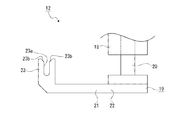
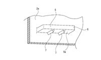
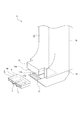
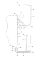
- FIG. 2 shows an embodiment of the present invention together with Figs. 2 to 30, and is a perspective view showing a first holding arm of a work jig. It is a side view which shows the 2nd holding arm of a work jig. It is a bottom view of the vehicle lamp. It is a side view of a vehicle lamp. It is a perspective view of a protrusion for grasping. It is a perspective view showing a 1st holding arm and a projection for grasping.
- FIG. 3 is a side view showing a state immediately before a vehicle lamp is held by a work jig.
- FIG. 3 is a side view showing a state in which the vehicle lamp is held by a work jig.
- FIG. 10 to 22 show another example of the engaging projections, and this drawing shows an example in which two engaging projections are provided in a protruding direction from the bottom surface of the gripping projection.
- FIG. It is a figure which shows the example provided in the state which the two engaging protrusions incline with respect to the width direction of the grasping protrusion. It is a figure which shows the example in which three engagement protrusions were provided apart. It is a figure which shows the example in which several engaging protrusions were formed in a C-shape continuously. It is a figure which shows the example in which several engaging protrusions were formed continuously in U shape. It is a figure which shows the example in which several engaging protrusions were continuously formed in H shape.
- FIG. 6 is a diagram showing an example in which a plurality of engaging protrusions are continuously formed and are separated from each other. It is a figure which shows the example of the engaging protrusion formed in the cross-sectional shape at right angled triangle. It is a figure which shows the example of the engagement protrusion formed in the shape which a front-end
- FIGS. 24 to 30 show the positional relationship between the formation position of the grip projection and the formation position of the insertion projection, or the positional relationship of a plurality of grip projections.
- FIG. It is a figure which shows the example which the protrusion for insertion was located in each vertex of a right triangle.
- ⁇ Vehicle parts or vehicle lamps are carried and assembled by being held by a work jig in each process during manufacturing.
- the movement direction of each part of the work jig is the up-down direction and the front-back direction, and the up-down, front-back, left-right directions are shown. Note that the up, down, front, back, left, and right directions shown below are shown for convenience of description, and the present invention is not limited to these directions and applied.
- a lamp housing is shown as an example of a vehicle component, but the application of the vehicle component of the present invention is not limited to the lamp housing, and a vehicle lamp such as a vehicle headlamp or a vehicle marker lamp is used. It can be applied to various vehicle parts such as a cover, a lens, a reflector, an extension, and a shade, which form a part of the vehicle.
- the work jig can be moved, for example, in any direction of up, down, left, right, front and back.
- the work jig is operated in order to carry and assemble the vehicle lamp by holding the vehicle lamp or a vehicle component forming a part of the vehicle lamp in each step of manufacturing the vehicle lamp. It has arms 11, 11 and a second holding arm 12. Each part of the first holding arms 11 and 11 and the second holding arm 12 is formed of, for example, a metal material.
- the work jig is provided with a main body base (not shown) on the upper end side, and the upper ends of the first holding arms 11 and 11 and the second holding arm 12 are connected to the main body base.
- the first holding arms 11 and 11 are spaced apart from each other on the left and right, and the second holding arm 12 is located between the first holding arms 11 and 11.
- the work jig may be configured to have three or more first holding arms 11 and not the second holding arms 12.
- the first holding arm 11 has a support pillar 13 that extends vertically and a movable portion 14 that can move in the vertical direction with respect to the support pillar 13 by an air cylinder mechanism or the like (see FIG. 1 ).
- a first grip 15 protruding forward is provided at the lower end of the support pillar 13.
- the lower surface of the first grip portion 15 is formed as a holding portion 15a composed of a plurality of irregularities arranged side by side.
- the movable portion 14 has a supported portion 16 extending vertically and a second grip portion 17 protruding forward from a lower end portion of the supported portion 16, and the supported portion 16 is movably supported by the support pillar 13. ing. Pressing ridges 17a, 17a are provided on the upper surface of the tip end portion of the second grip portion 17 so as to be separated from each other in the front-rear direction.
- the pressing ridges 17a, 17a are formed in a shape that tapers in the upward direction, and is formed in a shape that extends in the left-right direction.
- the pressing ridges 17a, 17a are located directly below the pressing portion 15a. Therefore, when the movable portion 14 is moved in the vertical direction with respect to the support pillar 13, the pressing ridges 17a, 17a are brought into contact with and separated from the pressing portion 15a.
- the second holding arm 12 has a support base 18 that extends vertically and a movable base 19 that can move in the vertical direction with respect to the support base 18 by an air cylinder mechanism or the like (see FIG. 2).
- the movable base 19 has a vertically extending shaft portion 20 and a base portion 21 connected to the shaft portion 20, and the shaft portion 20 is movably supported by the support base 18.
- the base portion 21 has a flat plate-like connecting plate portion 22 that faces in the vertical direction and an insertion support portion 23 that protrudes upward from the front end portion of the connecting plate portion 22, and the rear end portion of the connecting plate portion 22 is the shaft portion 20. Is connected to the lower end of.
- the insertion support portion 23 is formed with an insertion hole 23a that is open upward and left and right.
- Guide slant portions 23b, 23b are formed at the upper edge of the insertion support portion 23 at the opening edge of the insertion hole 23a, and the slant guide portions 23b, 23b are slanted in a direction away from each other as they go upward.
- the vehicular lamp 1 includes a lamp housing that has an opening and is a vehicular component 2, and a cover 3 that closes the opening of the lamp housing (see FIGS. 3 and 4).
- the lamp housing and the cover 3 constitute a lamp outer casing 4, and the internal space of the lamp outer casing 4 is formed as a lamp chamber.
- Required parts such as reflectors, extensions and shades are arranged in the lamp chamber.
- the vehicle component 2 has a bottom surface portion 2a located below and a wall surface portion 2b protruding substantially upward from a part of an outer peripheral portion of the bottom surface portion 2a when the vehicle lighting device 1 is attached to a vehicle body. Each part is integrally formed of a resin material.
- the wall surface portion 2b is a portion positioned as a rear surface portion, a front surface portion or a side surface portion when the vehicular lamp 1 is attached to the vehicle body.
- the vehicle component 2 is provided with gripping protrusions 5 and 5 protruding from the bottom surface 2a in the same direction, separated from each other on the left and right (see FIGS. 3 and 5).
- the grip projections 5 and 5 are provided as a first grip projection 5A and a second grip projection 5B, respectively.
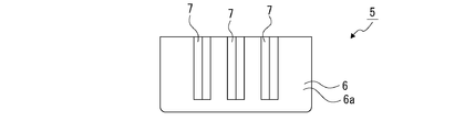
- the grip projections 5 and 5 are integrally formed with the bottom surface 2a, and are composed of a flat plate-shaped projection surface 6 and engagement projections 7 and 7 projected from the projection surface 6 (see FIG. 4).
- the grip projection 5 is not limited to the bottom surface 2a, and may be, for example, the wall surface 2b or any part of the vehicle component 2. However, it is desirable that the grip projection 5 is provided in a non-designed portion that is not visible from the outside or a portion that is unlikely to interfere with other components when the vehicular lamp 1 is attached to the vehicle body.
- the arrangement direction of the gripping protruding portions 5 and 5 is the width direction, and the direction orthogonal to the width direction and orthogonal to the protruding direction from the bottom surface portion 2a is the thickness direction.
- One surface in the thickness direction of the projecting surface portion 6 is formed as a first surface 6a, and the other surface in the thickness direction is formed as a second surface 6b.
- the second surface 6b is formed into a flat surface.
- the engaging projections 7, 7 are projected from the first surface 6a of the projecting surface portion 6 and are located apart from each other in the width direction of the projecting surface portion 6.
- the engaging projection 7 is formed in a shape extending in the protruding direction from the bottom surface 2a of the protruding surface portion 6, and is formed in a taper shape as it goes in the protruding direction from the protruding surface portion 6.
- the cross-sectional shape is an isosceles triangle. It is formed in a shape.
- the interval between the engaging protrusions 7, 7 is shorter than the length of the pressing protrusion 17 a provided on the first holding arm 11.
- the vehicular component 2 is provided with an insertion projection 8 that is projected from an end of the bottom surface 2a near the wall surface portion 2b or an end of the wall surface portion 2b near the bottom surface portion 2a (see FIGS. 3 and 4). ).
- the insertion projection 8 is projected in a direction orthogonal to the grip projection 5, and the width direction is the same as the width direction of the grip projection 5.
- the projection 8 for insertion is provided in a non-designed portion that is not visible from the outside or a portion that is unlikely to interfere with other components when the vehicle lamp 1 is attached to the vehicle body.
- the insertion projection 8 is located on the center line P of the grip projections 5 and 5 (see FIG. 3). Therefore, an isosceles triangle is formed by the straight lines Q, Q, and Q that connect the gripping projections 5 and 5 and the insertion projection 8, respectively, and the gripping projections 5 and 5 and the insertion projection 8 are respectively isosceles triangles. It is located at each vertex of.
- the gripping projections 5 and 5 provided on the vehicular component 2 are projected rearward and the insertion projection 8 is downward. It is mounted on a mounting table or the like (not shown) in the direction in which it is projected.
- the gripping protrusions 5 and 5 are horizontally separated from each other, and the insertion protrusion 8 is positioned below the gripping protrusions 5 and 5.
- the work jig is located behind the vehicle component 1.
- the work jig is a movable part of the first holding arms 11 and 11 so that the first grips 15 and 15 and the second grips 17 and 17 are located substantially right behind the grip projections 5 and 5, respectively. 14, 14 are moved in the vertical direction (see FIG. 6). At the same time, in the work jig, the movable base 19 of the second holding arm 12 is moved in the vertical direction so that the insertion support portion 23 is positioned slightly below the position directly behind the insertion projection 8.
- the work jig is moved forward (see Figure 7).
- the first grip portion 15 and the second grip portion 17 are positioned above and below the grip projection 5, and the insertion support 23 is positioned directly below the insertion projection 8. To be done.
- the second grip 17 When the movable portion 14 is moved upward, the second grip 17 is pressed against the grip projection 5 from below and the grip projection 5 is lifted to move the first grip 15 and the second grip. It is sandwiched by 17 from above and below. In the state where the gripping projection 5 is sandwiched between the first grip 15 and the second grip 17, the second surface 6 b of the grip projection 5 is attached to the pressing portion 15 a of the first grip 15. The pressing projections 17a, 17a of the second grip portion 17 are engaged with the engagement projections 7, 7 of the grip projection portion 5 while being pressed.
- the first grip 15 is in a state of being fixed without being moved in the vertical direction, and the second surface 6b formed in a plane is pressed against the pressing portion 15a. Therefore, the second surface 6b serves as a reference surface in the vertical direction when the vehicular lamp 1 is held by the work jig.
- the pressing protrusions 17a, 17a of the second grip portion 17 are formed in a shape that tapers as they go upward, and the engaging protrusions 7, 7 of the gripping protrusion 5 extend in the protruding direction from the protruding surface portion 6. Since the pressing projections 17a, 17a are engaged with the engaging projections 7, 7, since the pressing projections 17a, 17a are engaged with the engaging projections 7, a part of the pressing projections 17a, 17a is formed. , 7 is cut into the state. Therefore, the holding force of the second grip 17 with respect to the grip projection 5 is increased, and the grip projection 5 is gripped in a stable state by the first grip 15 and the second grip 17. ..
- the pressing portion 15a of the first grip portion 15 is formed by a plurality of irregularities arranged side by side, the grip projection 5 is gripped by the first grip portion 15 and the second grip portion 17.
- the pressing portion 15a may be formed by a plurality of concaves and convexes arranged in the front and rear, and in this case, the gripping protrusion 5 is particularly difficult to be displaced in the front-rear direction with respect to the first gripping portion 15. .
- the pressing portion 15a may be configured by a plurality of concaves and convexes arranged in a direction inclined with respect to the front, rear, left, and right. It becomes difficult to displace in the front-back direction and the left-right direction.
- the insertion projection 8 is relatively inserted from above into the insertion hole 23a of the insertion support 23.
- the guide support inclined portions 23b and 23b are formed at the opening edge of the insertion hole 23a in the insertion support portion 23, the insertion protrusion 8 is guided by the guide inclined portions 23b and 23b and smoothly inserted into the insertion hole 23a. Is inserted.
- the gripping projections 5 and 5 are sandwiched by the first gripping portions 15 and 15 and the second gripping portions 17 and 17 from above and below, respectively, and the insertion projection 8 is inserted into the insertion support portion 23.
- the vehicular lamp 1 is held by the work jig.
- the vehicle lamp 1 held by the work jig is transported to a predetermined position by the work jig, for example.
- the gripping projections 5 and 5 are released from the gripping state by the first gripping portions 15 and 15 and the second gripping portions 17 and 17, and the insertion projection is released.
- the portion 8 is pulled out from the insertion hole 23a of the insertion support portion 23, and the holding state of the vehicular lamp 1 by the work jig is released.
- the plurality of grip projections 5 that are gripped by being clamped from the opposite direction by the first holding arm 11 of the work jig are provided.
- the gripping projection 5 is provided with surfaces on both sides in the gripping direction gripped by the first holding arm 11 as a first surface 6a and a second surface 6b.
- a plurality of engaging projections 7 are provided that project from the surface 6a in the gripping direction and engage with the pressing projections 17a of the first holding arm 11.
- the plurality of engaging protrusions 7 provided so as to project from the first surface 6a in the gripping direction are held by the first holding arm 11 while being engaged with the pressing protrusions 17a, a plurality of engaging protrusions 7 are held.
- the gripping projection 5 is sandwiched and gripped by the first holding arm 11 from both sides in a state where a part of the first holding arm 11 is pressed against the engaging projection 7, The holding force of the holding arm 11 is increased, and a stable holding state by the work jig can be secured without increasing the size of the gripping protrusion 5.
- the second surface 6b of the grip projection 5 is formed to be a flat surface, the second surface 6b can be used as a reference surface when gripping with the work jig, and the vehicular lamp 1 Alternatively, it is possible to improve the positional accuracy of the vehicle lamp 1 or the vehicle component 2 with respect to the work jig while the vehicle component 2 is held by the work jig.
- the vehicle component 2 is provided with an insertion projection 8 that is supported by being inserted into the second holding arm 12 of the work jig. Therefore, the plurality of gripping projections 5 are gripped by the first holding arm 11 respectively, and the insertion projection 8 is inserted into and supported by the second holding arm 12 to hold the vehicle component 2. Therefore, the vehicular component 2 is gripped or supported at at least three places, and the vehicular lamp 1 or the vehicular component 2 can be held in a stable state by a work jig with a simple configuration.
- the two gripping projections 5 are positioned above the insertion projection 8 in the horizontal direction and separated from each other.
- the insertion protrusion 8 is located on the center line P of the two gripping protrusions 5.
- the vehicle lamp 1 or the vehicle component 2 can be stably held by the work jig. Can be held.
- the example of the engaging projections 7 and 7 which are separated in the width direction of the gripping projection 5 and extend in the projecting direction from the bottom surface portion 2a of the gripping projection 5 is shown.
- 7 may be provided apart from each other in the protruding direction from the bottom surface portion 2a of the gripping projection 5 (see FIG. 9), and at least one of them is inclined with respect to the width direction of the gripping projection 5. It may be provided (see FIG. 10).
- the number of the engaging protrusions 7 may be three or more as long as it is plural, and for example, the three engaging protrusions 7, 7, 7 may be provided separately (see FIG. 11). ).
- a plurality of engaging protrusions 7 may be provided continuously, and in this case, for example, a U-shape (see FIG. 12), a U-shape (see FIG. 13), an H-shape (see FIG. 14). (Refer to FIG. 15) and a frame shape (see FIG. 15). Further, a plurality of these various shapes may be provided separately (see FIG. 16).
- the grip projection 5 may be provided with a plurality of engagement projections 7 that are separated from each other in any direction or continuously provided in any direction. Since it also functions as a reinforcing rib, it is possible to secure a high reinforcing effect of the gripping projection 5 by increasing the number of the engagement projections 7, the continuous shape of the engagement projections 7, and the like. It becomes possible to secure a stable holding state by the first grip 15 and the second grip 17 depending on the shape and number of the engaging projections 7, and it is possible to improve the degree of freedom in design. ..
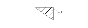
- the engagement projection 7 is formed in the shape of an isosceles triangle in which the cross-sectional shape is tapered.
- the engagement projection 7 is formed in any triangular shape in the cross-section.
- one base angle may be formed in a triangular shape with a right angle (see FIG. 17).
- the engaging projection 7 may have a cross-sectional shape with a tip having a curved surface (see FIG. 18), or may have a shape other than a triangle such as a trapezoid (see FIG. 19). ), and may be formed in a shape in which a concave portion is formed at the tip portion (see FIG. 20). Further, the engaging projection 7 may be formed in a shape in which different shapes are continuous in the projecting direction from the projecting surface portion 6 in the cross-sectional shape, for example, a shape in which a rectangular shape and a triangular shape are continuous (see FIG. 21). Alternatively, the trapezoidal shape and the triangular shape may be formed continuously (see FIG. 22).
- the engaging projection 7 By thus forming the engaging projection 7 in an arbitrary shape, the strength of the grip projection 5 is increased, and a stable holding state by the first grip 15 and the second grip 17 is secured. It becomes possible to improve the degree of freedom in design.
- the portion 8 may be configured to be located at each vertex of an arbitrary triangle.
- the gripping protrusions 5 and 5 and the insertion protrusion 8 may be disposed at each vertex of a right triangle whose base angle is a right angle. It may be located (see FIG. 23).
- the vehicle component 2 may not be provided with the insertion protrusion 8 but may be provided with three gripping protrusions 5, 5, 5.
- the work jig is provided with three first holding arms 11, 11, 11 and the holding projections 5, 5, 5 are held by the first holding arms 11, 11, 11 respectively. ..
- the gripping protrusions 5, 5, 5 may be arranged at the respective vertices of an arbitrary triangle.
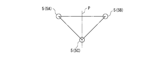
- the first gripping projection 5A which is one of the gripping projections 5 and 5, and the second gripping projection 5B are spaced apart in the horizontal direction, and the first gripping projection 5A and the second grip
- the third gripping projection 5C may be located on the center line P of the projecting projection 5B, and the gripping projections 5, 5 and 5 may be located at each vertex of the isosceles triangle as a whole (FIG. 24). reference).
- the first gripping projection 5A, the second gripping projection 5B, and the third gripping projection 5C are placed in the above-described positional relationship, so that the three gripping projections 5, 5, 5, Since the positional relationship of 1 is positioned at each vertex of the isosceles triangle, the vehicle lamp 1 or the vehicle component 2 can be stably held by the work jig.
- grip projections 5 and insertion projections 8 may be provided in total.
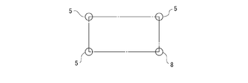
- the two grip projections 5 and 5 and the two insertion projections 8 and 8 are square or rectangular. May be configured to be located at each apex of each (see FIG. 25), or the three gripping protrusions 5, 5, 5 may be configured to be located at each apex of a square or a rectangle (FIG. 26). , May be arranged at each vertex of a square or a rectangle (see FIG. 27).
- grip projections 5 and insertion projections 8 are provided in total
- two grip projections 5 and 5 and two insertion projections 8 and 8 are provided.
- Three gripping protrusions 5, 5, 5 and one insertion protrusion 8 may be provided, and four gripping protrusions 5, 5,... Are provided. Good.
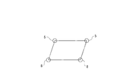
- the protrusions 5, 5,... May be arranged at each vertex of the trapezoid (see FIG. 28) or may be arranged at each vertex of the parallelogram (FIG. 29). (Refer to FIG. 30).
- the engagement projection 7 may be provided on the second surface 6b side, for example. It may be provided, or may be provided on both the first surface 6a side and the second surface 6b side.
- SYMBOLS 1... Vehicle lamp, 2... Vehicle parts, 5... Gripping projection, 6a... 1st surface, 6b... 2nd surface, 7... Engaging projection, 8... Inserting projection, 11... 1 holding arm, 12... 2nd holding arm, 23a... insertion hole, 5A... 1st grasping protrusion, 5B... 2nd grasping protrusion, 5C... 3rd grasping protrusion
Landscapes
- Engineering & Computer Science (AREA)
- General Engineering & Computer Science (AREA)
- Mechanical Engineering (AREA)
- Robotics (AREA)
- Lighting Device Outwards From Vehicle And Optical Signal (AREA)
Abstract
ワーク治具の第1の保持アーム(11)に反対方向から挟持されることにより把持される複数の把持用突部(5)を備え、把持用突部は第1の保持アームに把持される把持方向における両側の面が第1の面(6a)と第2の面(6b)として形成され、把持用突部に第1の面から把持方向へ突出され第1の保持アームが係合される複数の係合突部(7)が設けられた。これにより、第1の面から把持方向へ突出されて設けられた複数の係合突部が第1の保持アームに係合された状態で第1の保持アームによって保持されるため、複数の係合突部に第1の保持アームの一部が押し付けられた状態で把持用突部が第1の保持アームによって両側から挟持されて把持され、把持用突部の大型化を来すことなくワーク治具による安定した保持状態を確保することができる。
Description
本発明は、ワーク治具の第1の保持アームに反対方向から挟持されることにより把持される複数の把持用突部を備えた車輌用部品及びこれを備えた車輌用灯具についての技術分野に関する。
車輌用前照灯や車輌用標識灯等の車輌用灯具の一部を構成するランプハウジング、カバー、レンズ、リフレクター、エクステンション、シェード等の車輌用部品は、製造時の各工程においてワーク治具に保持されて搬送や組立等が行われる(例えば、特許文献1参照)。
ワーク治具には車輌用部品を保持するための複数の第1の保持アームが設けられており、車輌用部品には第1の保持アームによって把持される複数の把持用突部が設けられているものがある。
車輌用灯具における製造時の各工程では、車輌用部品が載置テーブル等の載置部に載置された状態において、ワーク治具の各部が所定の各方向へ移動され、各把持用突部がそれぞれ第1の保持アームによって把持されることにより車輌用部品が保持され、載置部から取り出される。載置部から取り出された車輌用部品はワーク治具によって他の載置部等の所定の位置に搬送され、次の工程において組立や検査や梱包等が行われる。
上記のように、車輌用灯具における製造時の各工程において、車輌用部品は各把持用突部がそれぞれ第1の保持アームによって把持されることによりワーク治具に保持され、ワーク治具によって他の載置部等の所定の位置に搬送される。従って、車輌用灯具における製造時の各工程において、車輌用部品がワーク治具によって安定した状態で保持される必要がある。
一方、ワーク治具による車輌用部品の安定した保持状態を確保するためには、例えば、把持用突部を大きくして把持用突部における第1の保持アームによる把持面積を大きくすることが望ましいが、把持用突部が大きくなってしまうと、把持用突部が他の車輌用部品や車輌の組付状態において車体の各部に干渉する可能性が高くなる。
そこで、本発明の車輌用部品及び車輌用灯具は、把持用突部の大型化を来すことなくワーク治具による安定した保持状態を確保することを目的とする。
第1に、本発明に係る車輌用部品は、車輌用灯具の一部を構成する車輌用部品であって、ワーク治具の第1の保持アームに反対方向から挟持されることにより把持される複数の把持用突部を備え、前記把持用突部は前記第1の保持アームに把持される把持方向における両側の面が第1の面と第2の面として形成され、前記把持用突部に前記第1の面から把持方向へ突出され前記第1の保持アームが係合される複数の係合突部が設けられたものである。
これにより、車輌用部品は第1の面から把持方向へ突出されて設けられた複数の係合突部が第1の保持アームに係合された状態で第1の保持アームによって保持されるため、複数の係合突部に第1の保持アームの一部が押し付けられた状態で把持用突部が第1の保持アームによって両側から挟持されて把持される。
第2に、上記した本発明に係る車輌用部品においては、前記第2の面が平面に形成されることが望ましい。
これにより、第2の面をワーク治具によって把持するときの基準面にすることが可能になる。
第3に、上記した本発明に係る車輌用部品においては、前記把持用突部が第1の把持用突部と第2の把持用突部と第3の把持用突部として三つ設けられ、前記ワーク治具に保持される状態において、前記第1の把持用突部と前記第2の把持用突部が水平方向に離隔して位置されると共に前記第3の把持用突部が前記第1の把持用突部と前記第2の把持用突部の下方において前記第1の把持用突部と前記第2の把持用突部の中央線上に位置されることが望ましい。
これにより、第1の把持用突部と第2の把持用突部と第3の把持用突部の位置関係が二等辺三角形の各頂点に位置される関係になる。
第4に、上記した本発明に係る車輌用部品においては、前記ワーク治具に挿入穴を有する第2の保持アームが設けられ、前記挿入穴に挿入されることにより支持される挿入用突部が設けられることが望ましい。
これにより、複数の把持用突部がそれぞれ第1の保持アームに把持されると共に挿入用突部が第2の保持アームに挿入されて支持されることにより車輌用部品が保持されるため、車輌用部品を少なくとも3箇所で把持又は支持することになる。
第5に、上記した本発明に係る車輌用部品においては、前記把持用突部が二つ設けられ、前記ワーク治具に保持される状態において、前記二つの把持用突部が前記挿入用突部の上側において水平方向に離隔して位置されると共に前記挿入用突部が前記二つの把持用突部の中央線上に位置されることが望ましい。
これにより、二つの把持用突部と挿入用突部が二等辺三角形の各頂点に位置される位置関係になる。
第6に、本発明に係る車輌用灯具は、ワーク治具の第1の保持アームに反対方向から挟持されることにより把持される複数の把持用突部を備え、前記把持用突部は前記第1の保持アームに把持される把持方向における両側の面が第1の面と第2の面として形成され、前記把持用突部に前記第1の面から把持方向へ突出され前記第1の保持アームが係合される複数の係合突部が設けられたものである。
これにより、車輌用灯具は第1の面から把持方向へ突出されて設けられた複数の係合突部が第1の保持アームに係合された状態で第1の保持アームによって保持されるため、複数の係合突部に第1の保持アームの一部が押し付けられた状態で把持用突部が第1の保持アームによって両側から挟持されて把持される。
本発明によれば、第1の面から把持方向へ突出されて設けられた複数の係合突部が第1の保持アームに係合された状態で第1の保持アームによって保持されるため、複数の係合突部に第1の保持アームの一部が押し付けられた状態で把持用突部が第1の保持アームによって両側から挟持されて把持され、把持用突部の大型化を来すことなくワーク治具による安定した保持状態を確保することができる。
以下に、本発明の車輌用部品及び車輌用灯具を実施するための形態について添付図面を参照して説明する。
車輌用部品又は車輌用灯具は、製造時の各工程においてワーク治具に保持されて搬送や組立等が行われる。
以下の説明においては、ワーク治具の各部の移動方向を上下方向及び前後方向として上下前後左右の方向を示す。尚、以下に示す上下前後左右の方向は、説明の便宜上示すものであり、本発明はこれらの方向に限定して適用されることはない。
また、以下には、車輌用部品としてランプハウジングを例として示すが、本発明車輌用部品の適用はランプハウジングに限られることはなく、車輌用前照灯や車輌用標識灯等の車輌用灯具の一部を構成するカバー、レンズ、リフレクター、エクステンション、シェード等の各種の車輌用部品に適用することが可能である。
先ず、ワーク治具について説明する(図1及び図2参照)。
ワーク治具は、例えば、上下左右前後の何れの方向へも移動可能にされている。ワーク治具は車輌用灯具の製造時の各工程において車輌用灯具又は車輌用灯具の一部をを構成する車輌用部品を保持して搬送や組立等を行うために動作され、第1の保持アーム11、11と第2の保持アーム12を有している。第1の保持アーム11、11と第2の保持アーム12は各部が、例えば、金属材料によって形成されている。
ワーク治具には上端側に図示しない本体ベースが設けられ、第1の保持アーム11、11と第2の保持アーム12は上端部が本体ベースに連結されている。第1の保持アーム11、11は左右に離隔して位置され、第1の保持アーム11、11間に第2の保持アーム12が位置されている。
尚、ワーク治具は三つ以上の第1の保持アーム11を有し第2の保持アーム12を有していない構成にされていてもよい。
第1の保持アーム11は上下に延びる支持ピラー13とエアーシリンダー機構等によって支持ピラー13に対して上下方向へ移動可能な可動部14とを有している(図1参照)。
支持ピラー13の下端部には前方に突出された第1の把持部15が設けられている。第1の把持部15の下面は左右に並ぶ複数の凹凸によって構成された押さえ部15aとして形成されている。
可動部14は上下に延びる被支持部16と被支持部16の下端部から前方に突出された第2の把持部17とを有し、被支持部16が支持ピラー13に移動可能に支持されている。第2の把持部17における先端部の上面には押さえ突条17a、17aが前後に離隔して設けられている。押さえ突条17a、17aは上方へ行くに従って先細りとなる形状に形成され、左右に延びる形状に形成されている。
押さえ突条17a、17aは押さえ部15aの真下に位置されている。従って、可動部14が支持ピラー13に対して上下方向へ移動されると、押さえ突条17a、17aが押さえ部15aに離接される。
第2の保持アーム12は上下に延びる支持ベース18とエアーシリンダー機構等によって支持ベース18に対して上下方向へ移動可能な可動ベース19とを有している(図2参照)。
可動ベース19は上下に延びる軸部20と軸部20に連結されたベース部21とを有し、軸部20が支持ベース18に移動可能に支持されている。ベース部21は上下方向を向く平板状の連結板部22と連結板部22の前端部から上方に突出された挿入支持部23とを有し、連結板部22の後端部が軸部20の下端部に連結されている。挿入支持部23には上方及び左右に開口された挿入穴23aが形成されている。
挿入支持部23の上端部には挿入穴23aの開口縁に案内傾斜部23b、23bが形成され、案内傾斜部23b、23bは上方へ行くに従って互いに離隔する方向へ傾斜されている。
次に、ワーク治具によって保持される車輌用灯具について説明する(図3乃至図5参照)。
車輌用灯具1は、開口を有し車輌用部品2であるランプハウジングと、ランプハウジングの開口を閉塞するカバー3とを備えている(図3及び図4参照)。ランプハウジングとカバー3によって灯具外筐4が構成され、灯具外筐4の内部空間が灯室として形成されている。灯室には所要の各部、例えば、リフレクターやエクステンションやシェード等が配置される。
車輌用部品2は車輌用灯具1が車体に取り付けられた状態において下方に位置する底面部2aと底面部2aにおける外周部の一部から略上方に突出された壁面部2bとを有し、例えば、樹脂材料によって各部が一体に形成されている。壁面部2bは車輌用灯具1が車体に取り付けられた状態において後面部、前面部又は側面部として位置される部分である。
車輌用部品2には底面部2aから同じ方向へ突出された把持用突部5、5が左右に離隔して設けられている(図3及び図5参照)。把持用突部5、5はそれぞれ第1の把持用突部5Aと第2の把持用突部5Bとして設けられている。把持用突部5、5は底面部2aと一体に形成され、平板状の突面部6と突面部6から突出された係合突部7、7とから成る(図4参照)。
尚、把持用突部5は底面部2aに限らず、例えば、壁面部2bから突出されていてもよく、車輌用部品2の何れの部分から突出されていてもよい。但し、把持用突部5は車輌用灯具1が車体に取り付けられた状態において、外部から視認されない非意匠部分や他の部品と干渉され難い部分に設けられることが望ましい。
突面部6は、把持用突部5、5の並び方向が幅方向とされ、幅方向に直交し底面部2aからの突出方向に直交する方向が厚み方向とされている。突面部6は厚み方向における一方の面が第1の面6aとして形成され厚み方向における他方の面が第2の面6bとして形成されている。第2の面6bは平面に形成されている。
係合突部7、7は突面部6の第1の面6aから突出され突面部6の幅方向において離隔して位置されている。係合突部7は突面部6の底面部2aからの突出方向に延びる形状に形成され、突面部6からの突出方向へ行くに従って先細りとなる形状に形成され、例えば、断面形状が二等辺三角形状に形成されている。係合突部7、7間の間隔は第1の保持アーム11に設けられた押さえ突条17aの長さより短くされている。
車輌用部品2には底面部2aの壁面部2b寄りの端部又は壁面部2bの底面部2a寄りの端部から突出された挿入用突部8が設けられている(図3及び図4参照)。挿入用突部8は把持用突部5に対して直交する方向に突出され、幅方向が把持用突部5の幅方向と同じにされている。
挿入用突部8は車輌用灯具1が車体に取り付けられた状態において、外部から視認されない非意匠部分や他の部品と干渉され難い部分に設けられることが望ましい。
挿入用突部8は把持用突部5、5の中央線P上に位置されている(図3参照)。従って、把持用突部5、5と挿入用突部8をそれぞれ結ぶ直線Q、Q、Qによって二等辺三角形が形成され、把持用突部5、5と挿入用突部8はそれぞれ二等辺三角形の各頂点に位置されている。
次に、ワーク治具によって車輌用灯具1が保持されるときのワーク治具の動作について説明する(図6乃至図8参照)。
車輌用灯具1がワーク治具に保持される状態において、車輌用灯具1は、例えば、車輌用部品2に設けられた把持用突部5、5が後方に突出され挿入用突部8が下方に突出される向きで図示しない載置台等に載置される。把持用突部5、5は水平方向に離隔して位置され、挿入用突部8は把持用突部5、5の下方に位置される。このときワーク治具は車輌用部品1の後方に位置されている。
ワーク治具は第1の把持部15、15と第2の把持部17、17がそれぞれ把持用突部5、5の略真後ろに位置されるように第1の保持アーム11、11の可動部14、14が上下方向へ移動される(図6参照)。同時に、ワーク治具は挿入支持部23が挿入用突部8の真後ろより稍下側に位置されるように第2の保持アーム12の可動ベース19が上下方向へ移動される。
次に、ワーク治具は前方へ移動される(図7参照)。ワーク治具が前方へ移動されると、第1の把持部15と第2の把持部17が把持用突部5の上下に位置され、挿入支持部23が挿入用突部8の真下に位置される。
続いて、第1の保持アーム11は可動部14が上方へ移動され、第2の保持アーム12は可動ベース19が上方へ移動される(図8参照)。
可動部14が上方へ移動されると、把持用突部5に下方から第2の把持部17が押し当てられ把持用突部5が持ち上げられて第1の把持部15と第2の把持部17によって上下から挟持される。第1の把持部15と第2の把持部17によって把持用突部5が挟持された状態においては、第1の把持部15の押さえ部15aに把持用突部5の第2の面6bが押し当てられると共に第2の把持部17の押さえ突条17a、17aが把持用突部5の係合突部7、7に係合される。
このとき第1の把持部15は上下方向へ移動されず固定された状態であり、平面に形成された第2の面6bが押さえ部15aに押し当てられる。従って、第2の面6bは車輌用灯具1がワーク治具によって保持されるときの上下方向における基準面とされる。
また、第2の把持部17の押さえ突条17a、17aが上方へ行くに従って先細りとなる形状に形成され、把持用突部5の係合突部7、7が突面部6からの突出方向へ行くに従って先細りとなる形状に形成されているため、押さえ突条17a、17aが係合突部7、7に係合された状態において、押さえ突条17a、17aの一部が係合突部7、7に食い込まれた状態にされる。従って、把持用突部5に対する第2の把持部17の保持力が高くされており、把持用突部5が第1の把持部15と第2の把持部17によって安定した状態で把持される。
さらに、第1の把持部15の押さえ部15aが左右に並ぶ複数の凹凸によって構成されているため、把持用突部5が第1の把持部15と第2の把持部17によって把持された状態において、特に、第1の把持部15に対して左右方向へ変位し難く、把持用突部5の第1の把持部15と第2の把持部17による一層安定した把持状態が確保される。
このように把持用突部5は第1の把持部15と第2の把持部17によって安定した状態で保持されるため、底面部2aからの突出量や幅方向における大きさを小さくして小型にすることが可能である。
尚、押さえ部15aは前後に並ぶ複数の凹凸によって構成されていてもよく、この場合には、把持用突部5が、特に、第1の把持部15に対して前後方向へ変位し難くなる。また、押さえ部15aは前後左右に対して傾斜された方向に並ぶ複数の凹凸によって構成されていてもよく、この場合には、把持用突部5が、特に、第1の把持部15に対して前後方向及び左右方向へ変位し難くなる。
一方、可動ベース19が上方へ移動されると、挿入支持部23の挿入穴23aに挿入用突部8が相対的に上方から挿入される。このとき挿入支持部23には挿入穴23aの開口縁に案内傾斜部23b、23bが形成されているため、挿入用突部8が案内傾斜部23b、23bに案内されて円滑に挿入穴23aに挿入される。
上記のように、把持用突部5、5がそれぞれ第1の把持部15、15と第2の把持部17、17によって上下から挟持されると共に挿入用突部8が挿入支持部23の挿入穴23aに挿入されることにより、車輌用灯具1がワーク治具によって保持される。
ワーク治具によって保持された車輌用灯具1は、例えば、ワーク治具によって所定の位置まで搬送される。車輌用灯具1が所定の位置まで搬送されると、把持用突部5、5に対する第1の把持部15、15と第2の把持部17、17による把持状態が解除されると共に挿入用突部8が挿入支持部23の挿入穴23aから引き出され、ワーク治具による車輌用灯具1の保持状態が解除される。
以上に記載した通り、車輌用灯具1及び車輌用部品2にあっては、ワーク治具の第1の保持アーム11に反対方向から挟持されることにより把持される複数の把持用突部5が設けられ、把持用突部5は第1の保持アーム11に把持される把持方向における両側の面が第1の面6aと第2の面6bとして形成され、把持用突部5に第1の面6aから把持方向へ突出され第1の保持アーム11の押さえ突条17aが係合される複数の係合突部7が設けられている。
従って、第1の面6aから把持方向へ突出されて設けられた複数の係合突部7が押さえ突条17aに係合された状態で第1の保持アーム11によって保持されるため、複数の係合突部7に第1の保持アーム11の一部が押し付けられた状態で把持用突部5が第1の保持アーム11によって両側から挟持されて把持され、把持用突部5に対する第1の保持アーム11の保持力が高くされ、把持用突部5の大型化を来すことなくワーク治具による安定した保持状態を確保することができる。
また、把持用突部5の第2の面6bが平面に形成されているため、第2の面6bをワーク治具によって把持するときの基準面にすることが可能になり、車輌用灯具1又は車輌用部品2がワーク治具に保持された状態において車輌用灯具1又は車輌用部品2のワーク治具に対する位置精度の向上を図ることができる。
さらに、車輌用部品2にはワーク治具の第2の保持アーム12に挿入されることにより支持される挿入用突部8が設けられている。従って、複数の把持用突部5がそれぞれ第1の保持アーム11に把持されると共に挿入用突部8が第2の保持アーム12に挿入されて支持されることにより車輌用部品2が保持されるため、車輌用部品2を少なくとも3箇所で把持又は支持することになり、車輌用灯具1又は車輌用部品2をワーク治具によって簡易な構成によって安定した状態で保持することができる。
さらにまた、把持用突部5が二つ設けられ、ワーク治具に保持される状態において、二つの把持用突部5が挿入用突部8の上側において水平方向に離隔して位置されると共に挿入用突部8が二つの把持用突部5の中央線P上に位置される。
従って、二つの把持用突部5と挿入用突部8が二等辺三角形の各頂点に位置される位置関係になるため、車輌用灯具1又は車輌用部品2をワーク治具によって安定した状態で保持することができる。
次に、把持用突部5に設けられる係合突部7の別の例について説明する(図9乃至図22参照)。
上記には、把持用突部5の幅方向に離隔し把持用突部5の底面部2aからの突出方向に延びる係合突部7、7の例を示したが、係合突部7、7は、把持用突部5の底面部2aからの突出方向に離隔して設けられていてもよく(図9参照)、少なくとも一方が把持用突部5の幅方向に対して傾斜した状態で設けられていてもよい(図10参照)。
また、係合突部7の数も複数であれば三つ以上であってもよく、例えば、三つの係合突部7、7、7が離隔して設けられていてもよい(図11参照)。
さらに、複数の係合突部7が連続して設けられていてもよく、この場合に、例えば、コ字状(図12参照)、U字状(図13参照)、H字状(図14参照)、枠状(図15参照)等の各種の形状に形成されていてもよい。また、これらの各種の形状が複数離隔して設けられていてもよい(図16参照)。
このように把持用突部5には複数の係合突部7が任意の方向において離隔し又は任意の向きで連続して設けられていてもよく、係合突部7は把持用突部5の補強リブとしても機能するため、係合突部7の数の増加や係合突部7の連続する形状等によって把持用突部5の高い補強効果を確保することも可能であり、また、係合突部7の形状や数によって第1の把持部15と第2の把持部17による安定した保持状態を確保することが可能になり、設計の自由度の向上を図ることも可能になる。
また、上記には、係合突部7の形状が断面形状において先細りとなる二等辺三角形状に形成された例を示したが、係合突部7は断面形状において何れの三角形状に形成されていてもよく、例えば、一つの底角が直角にされた三角形状に形成されていてもよい(図17参照)。
さらに、係合突部7は断面形状において、先端部が曲面を有する形状に形成されていてもよく(図18参照)、台形等の三角形以外の形状に形成されていてもよく(図19参照)、先端部に凹部が形成された形状に形成されていてもよい(図20参照)。また、係合突部7は断面形状において、突面部6からの突出方向において異なる形状が連続する形状に形成されていてもよく、例えば、矩形状と三角形状が連続する形状(図21参照)や台形状と三角形状が連続する形状(図22参照)に形成されていてもよい。
このように係合突部7が任意の形状に形成されることにより、把持用突部5の強度を高めたり、第1の把持部15と第2の把持部17による安定した保持状態を確保することが可能になり、設計の自由度の向上を図ることも可能になる。
次いで、車輌用部品2における把持用突部5の形成位置と挿入用突部8の形成位置との位置関係又は複数の把持用突部5の位置関係について説明する(図23乃至図30参照)。
上記には、二つの把持用突部5、5と一つの挿入用突部8とがそれぞれ二等辺三角形の各頂点に位置する例を示したが、把持用突部5、5と挿入用突部8は任意の三角形の各頂点に位置する構成にされていてもよく、例えば、把持用突部5、5と挿入用突部8は底角の一つが直角である直角三角形の各頂点に位置されていてもよい(図23参照)。
また、車輌用部品2には挿入用突部8が設けられておらず、三つの把持用突部5、5、5が設けられていてもよい。この場合には、ワーク治具に三つの第1の保持アーム11、11、11が設けられ、把持用突部5、5、5がそれぞれ第1の保持アーム11、11、11に把持される。三つの把持用突部5、5、5が設けられている場合においても、把持用突部5、5、5は任意の三角形の各頂点に位置する構成にされていればよく、例えば、二つの把持用突部5、5である第1の把持用突部5Aと第2の把持用突部5Bが水平方向において離隔して位置され、第1の把持用突部5Aと第2の把持用突部5Bの中央線P上に第3の把持用突部5Cが位置され、全体として把持用突部5、5、5が二等辺三角形の各頂点に位置されていてもよい(図24参照)。
第1の把持用突部5Aと第2の把持用突部5Bと第3の把持用突部5Cが上記のような位置関係にされることにより、三つの把持用突部5、5、5の位置関係が二等辺三角形の各頂点に位置される関係になるため、車輌用灯具1又は車輌用部品2をワーク治具によって安定した状態で保持することができる。
また、把持用突部5と挿入用突部8は合計で四つ以上が設けられていてもよい。把持用突部5と挿入用突部8が合計で、例えば、四つ設けられている場合には、二つの把持用突部5、5と二つの挿入用突部8、8が正方形又は長方形の各頂点に位置する構成にされていてもよく(図25参照)、三つの把持用突部5、5、5が正方形又は長方形の各頂点に位置する構成にされていてもよく(図26参照)、四つの把持用突部5、5、・・・が正方形又は長方形の各頂点に位置する構成にされていてもよい(図27参照)。
さらに、把持用突部5と挿入用突部8が合計で、例えば、四つ設けられている場合に、二つの把持用突部5、5と二つの挿入用突部8、8が設けられていてもよく、三つの把持用突部5、5、5と一つの挿入用突部8が設けられていてもよく、四つの把持用突部5、5、・・・が設けられていてもよい。
この場合に、例えば、二つの把持用突部5、5と二つの挿入用突部8、8、三つの把持用突部5、5、5と一つの挿入用突部8又は四つの把持用突部5、5、・・・が、台形の各頂点に位置する構成にされていてもよく(図28参照)、平行四辺形の各頂点に位置する構成にされていてもよく(図29参照)、不等辺四角形の各頂点に位置する構成にされていてもよい(図30参照)。
上記のように、四つ以上の把持用突部5又は合計で四つ以上の把持用突部5と挿入用突部8が設けられる場合には、車輌用部品2を把持する部分の数が多く、ワーク治具による車輌用灯具1又は車輌用部品2のより安定した保持状態を確保することができる。
尚、上記には、第1の面6a側に係合突部7が設けられた把持用突部5の例を示したが、係合突部7は、例えば、第2の面6b側に設けられていてもよく、また、第1の面6a側と第2の面6b側の双方の側に設けられていてもよい。
1…車輌用灯具、2…車輌用部品、5…把持用突部、6a…第1の面、6b…第2の面、7…係合突部、8…挿入用突部、11…第1の保持アーム、12…第2の保持アーム、23a…挿入穴、5A…第1の把持用突部、5B…第2の把持用突部、5C…第3の把持用突部
Claims (6)
- 車輌用灯具の一部を構成する車輌用部品であって、
ワーク治具の第1の保持アームに反対方向から挟持されることにより把持される複数の把持用突部を備え、
前記把持用突部は前記第1の保持アームに把持される把持方向における両側の面が第1の面と第2の面として形成され、
前記把持用突部に前記第1の面から把持方向へ突出され前記第1の保持アームが係合される複数の係合突部が設けられた
車輌用部品。 - 前記第2の面が平面に形成された
請求項1に記載の車輌用部品。 - 前記把持用突部が第1の把持用突部と第2の把持用突部と第3の把持用突部として三つ設けられ、
前記ワーク治具に保持される状態において、前記第1の把持用突部と前記第2の把持用突部が水平方向に離隔して位置されると共に前記第3の把持用突部が前記第1の把持用突部と前記第2の把持用突部の下方において前記第1の把持用突部と前記第2の把持用突部の中央線上に位置される
請求項1又は請求項2に記載の車輌用部品。 - 前記ワーク治具に挿入穴を有する第2の保持アームが設けられ、
前記挿入穴に挿入されることにより支持される挿入用突部が設けられた
請求項1又は請求項2に記載の車輌用部品。 - 前記把持用突部が二つ設けられ、
前記ワーク治具に保持される状態において、前記二つの把持用突部が前記挿入用突部の上側において水平方向に離隔して位置されると共に前記挿入用突部が前記二つの把持用突部の中央線上に位置される
請求項4に記載の車輌用部品。 - ワーク治具の第1の保持アームに反対方向から挟持されることにより把持される複数の把持用突部を備え、
前記把持用突部は前記第1の保持アームに把持される把持方向における両側の面が第1の面と第2の面として形成され、
前記把持用突部に前記第1の面から把持方向へ突出され前記第1の保持アームが係合される複数の係合突部が設けられた
車輌用灯具。
Priority Applications (1)
| Application Number | Priority Date | Filing Date | Title |
|---|---|---|---|
| JP2020566157A JP7350785B2 (ja) | 2019-01-16 | 2019-12-16 | 車輌用部品及び車輌用灯具 |
Applications Claiming Priority (2)
| Application Number | Priority Date | Filing Date | Title |
|---|---|---|---|
| JP2019-005055 | 2019-01-16 | ||
| JP2019005055 | 2019-01-16 |
Publications (1)
| Publication Number | Publication Date |
|---|---|
| WO2020149070A1 true WO2020149070A1 (ja) | 2020-07-23 |
Family
ID=71613112
Family Applications (1)
| Application Number | Title | Priority Date | Filing Date |
|---|---|---|---|
| PCT/JP2019/049208 Ceased WO2020149070A1 (ja) | 2019-01-16 | 2019-12-16 | 車輌用部品及び車輌用灯具 |
Country Status (2)
| Country | Link |
|---|---|
| JP (1) | JP7350785B2 (ja) |
| WO (1) | WO2020149070A1 (ja) |
Citations (6)
| Publication number | Priority date | Publication date | Assignee | Title |
|---|---|---|---|---|
| JPH08155865A (ja) * | 1994-12-05 | 1996-06-18 | Nippondenso Co Ltd | 搬送装置 |
| JP2548011Y2 (ja) * | 1991-04-04 | 1997-09-17 | 三菱自動車工業株式会社 | ランプの自動組付け装置におけるランプ把持装置 |
| JPH10235590A (ja) * | 1996-12-25 | 1998-09-08 | Araco Corp | ワークの把持装置 |
| JP2006007348A (ja) * | 2004-06-24 | 2006-01-12 | Daifuku Co Ltd | 把持装置 |
| JP2008272882A (ja) * | 2007-04-27 | 2008-11-13 | Nissan Motor Co Ltd | 部品投入方法および部品投入装置 |
| JP2011173218A (ja) * | 2010-02-25 | 2011-09-08 | Toyota Motor Corp | 搬送装置及びその位置決め方法 |
-
2019
- 2019-12-16 JP JP2020566157A patent/JP7350785B2/ja active Active
- 2019-12-16 WO PCT/JP2019/049208 patent/WO2020149070A1/ja not_active Ceased
Patent Citations (6)
| Publication number | Priority date | Publication date | Assignee | Title |
|---|---|---|---|---|
| JP2548011Y2 (ja) * | 1991-04-04 | 1997-09-17 | 三菱自動車工業株式会社 | ランプの自動組付け装置におけるランプ把持装置 |
| JPH08155865A (ja) * | 1994-12-05 | 1996-06-18 | Nippondenso Co Ltd | 搬送装置 |
| JPH10235590A (ja) * | 1996-12-25 | 1998-09-08 | Araco Corp | ワークの把持装置 |
| JP2006007348A (ja) * | 2004-06-24 | 2006-01-12 | Daifuku Co Ltd | 把持装置 |
| JP2008272882A (ja) * | 2007-04-27 | 2008-11-13 | Nissan Motor Co Ltd | 部品投入方法および部品投入装置 |
| JP2011173218A (ja) * | 2010-02-25 | 2011-09-08 | Toyota Motor Corp | 搬送装置及びその位置決め方法 |
Also Published As
| Publication number | Publication date |
|---|---|
| JP7350785B2 (ja) | 2023-09-26 |
| JPWO2020149070A1 (ja) | 2021-11-25 |
Similar Documents
| Publication | Publication Date | Title |
|---|---|---|
| US10052728B2 (en) | Assembling apparatus and assembling method | |
| JP6974996B2 (ja) | 車両用灯具 | |
| ITTO990792A1 (it) | Proiettore per veicolo | |
| WO2020149070A1 (ja) | 車輌用部品及び車輌用灯具 | |
| CN102798068B (zh) | 车辆用前照灯以及投影透镜的安装方法 | |
| JP3136469B2 (ja) | 車輌用灯具 | |
| JP5195460B2 (ja) | 車両用灯具 | |
| EP3222903B1 (fr) | Dispositif lumineux de véhicule automobile et procédé d'assemblage associé | |
| CN119836543A (zh) | 头灯组件和组装的方法 | |
| CN204300913U (zh) | 汽车前照灯 | |
| JP5277990B2 (ja) | 車両用灯具 | |
| JP2009248900A (ja) | 車両のランプユニット取付け構造 | |
| JP2011023140A (ja) | 車両用灯具 | |
| JP2010123519A (ja) | 車両用灯具 | |
| JP7266473B2 (ja) | 灯具ユニット | |
| JPH1055703A (ja) | 車輌用前照灯 | |
| US20240044468A1 (en) | Vehicle-mounted light source unit | |
| CN216532165U (zh) | 一种延展反射面的多曲面前照灯 | |
| CN115480336B (zh) | 导光模块 | |
| JPS6129127Y2 (ja) | ||
| WO2025263252A1 (ja) | 車輌用灯具 | |
| US3560733A (en) | Take-apart lamp harp | |
| JPH0110805Y2 (ja) | ||
| CN108620790B (zh) | 将支架固定在v型零件上的通用夹具 | |
| JPH0648645Y2 (ja) | 自動車用ヘッドランプにおけるビーム形成用シェード |
Legal Events
| Date | Code | Title | Description |
|---|---|---|---|
| 121 | Ep: the epo has been informed by wipo that ep was designated in this application |
Ref document number: 19910128 Country of ref document: EP Kind code of ref document: A1 |
|
| ENP | Entry into the national phase |
Ref document number: 2020566157 Country of ref document: JP Kind code of ref document: A |
|
| NENP | Non-entry into the national phase |
Ref country code: DE |
|
| 122 | Ep: pct application non-entry in european phase |
Ref document number: 19910128 Country of ref document: EP Kind code of ref document: A1 |