WO2020145247A1 - モーションコントローラ及び成形機 - Google Patents
モーションコントローラ及び成形機 Download PDFInfo
- Publication number
- WO2020145247A1 WO2020145247A1 PCT/JP2020/000099 JP2020000099W WO2020145247A1 WO 2020145247 A1 WO2020145247 A1 WO 2020145247A1 JP 2020000099 W JP2020000099 W JP 2020000099W WO 2020145247 A1 WO2020145247 A1 WO 2020145247A1
- Authority
- WO
- WIPO (PCT)
- Prior art keywords
- motion controller
- abnormality detection
- unit
- data collection
- data
- Prior art date
- Legal status (The legal status is an assumption and is not a legal conclusion. Google has not performed a legal analysis and makes no representation as to the accuracy of the status listed.)
- Ceased
Links
Images




Classifications
-
- B—PERFORMING OPERATIONS; TRANSPORTING
- B29—WORKING OF PLASTICS; WORKING OF SUBSTANCES IN A PLASTIC STATE IN GENERAL
- B29C—SHAPING OR JOINING OF PLASTICS; SHAPING OF MATERIAL IN A PLASTIC STATE, NOT OTHERWISE PROVIDED FOR; AFTER-TREATMENT OF THE SHAPED PRODUCTS, e.g. REPAIRING
- B29C45/00—Injection moulding, i.e. forcing the required volume of moulding material through a nozzle into a closed mould; Apparatus therefor
- B29C45/17—Component parts, details or accessories; Auxiliary operations
- B29C45/76—Measuring, controlling or regulating
-
- B—PERFORMING OPERATIONS; TRANSPORTING
- B29—WORKING OF PLASTICS; WORKING OF SUBSTANCES IN A PLASTIC STATE IN GENERAL
- B29C—SHAPING OR JOINING OF PLASTICS; SHAPING OF MATERIAL IN A PLASTIC STATE, NOT OTHERWISE PROVIDED FOR; AFTER-TREATMENT OF THE SHAPED PRODUCTS, e.g. REPAIRING
- B29C45/00—Injection moulding, i.e. forcing the required volume of moulding material through a nozzle into a closed mould; Apparatus therefor
- B29C45/03—Injection moulding apparatus
-
- G—PHYSICS
- G05—CONTROLLING; REGULATING
- G05B—CONTROL OR REGULATING SYSTEMS IN GENERAL; FUNCTIONAL ELEMENTS OF SUCH SYSTEMS; MONITORING OR TESTING ARRANGEMENTS FOR SUCH SYSTEMS OR ELEMENTS
- G05B19/00—Program-control systems
- G05B19/02—Program-control systems electric
- G05B19/18—Numerical control [NC], i.e. automatically operating machines, in particular machine tools, e.g. in a manufacturing environment, so as to execute positioning, movement or co-ordinated operations by means of program data in numerical form
-
- B—PERFORMING OPERATIONS; TRANSPORTING
- B29—WORKING OF PLASTICS; WORKING OF SUBSTANCES IN A PLASTIC STATE IN GENERAL
- B29C—SHAPING OR JOINING OF PLASTICS; SHAPING OF MATERIAL IN A PLASTIC STATE, NOT OTHERWISE PROVIDED FOR; AFTER-TREATMENT OF THE SHAPED PRODUCTS, e.g. REPAIRING
- B29C37/00—Component parts, details, accessories or auxiliary operations, not covered by group B29C33/00 or B29C35/00
- B29C2037/90—Measuring, controlling or regulating
- B29C2037/903—Measuring, controlling or regulating by means of a computer
-
- B—PERFORMING OPERATIONS; TRANSPORTING
- B29—WORKING OF PLASTICS; WORKING OF SUBSTANCES IN A PLASTIC STATE IN GENERAL
- B29C—SHAPING OR JOINING OF PLASTICS; SHAPING OF MATERIAL IN A PLASTIC STATE, NOT OTHERWISE PROVIDED FOR; AFTER-TREATMENT OF THE SHAPED PRODUCTS, e.g. REPAIRING
- B29C45/00—Injection moulding, i.e. forcing the required volume of moulding material through a nozzle into a closed mould; Apparatus therefor
- B29C45/17—Component parts, details or accessories; Auxiliary operations
- B29C45/76—Measuring, controlling or regulating
- B29C2045/7606—Controlling or regulating the display unit
-
- B—PERFORMING OPERATIONS; TRANSPORTING
- B29—WORKING OF PLASTICS; WORKING OF SUBSTANCES IN A PLASTIC STATE IN GENERAL
- B29C—SHAPING OR JOINING OF PLASTICS; SHAPING OF MATERIAL IN A PLASTIC STATE, NOT OTHERWISE PROVIDED FOR; AFTER-TREATMENT OF THE SHAPED PRODUCTS, e.g. REPAIRING
- B29C2945/00—Indexing scheme relating to injection moulding, i.e. forcing the required volume of moulding material through a nozzle into a closed mould
- B29C2945/76—Measuring, controlling or regulating
-
- B—PERFORMING OPERATIONS; TRANSPORTING
- B29—WORKING OF PLASTICS; WORKING OF SUBSTANCES IN A PLASTIC STATE IN GENERAL
- B29C—SHAPING OR JOINING OF PLASTICS; SHAPING OF MATERIAL IN A PLASTIC STATE, NOT OTHERWISE PROVIDED FOR; AFTER-TREATMENT OF THE SHAPED PRODUCTS, e.g. REPAIRING
- B29C2945/00—Indexing scheme relating to injection moulding, i.e. forcing the required volume of moulding material through a nozzle into a closed mould
- B29C2945/76—Measuring, controlling or regulating
- B29C2945/76451—Measurement means
Definitions
- the present invention relates to a motion controller and a molding machine.
- Patent Documents 1 and 2 there is known a technique of sensing the behavior of a mechanical device such as a molding machine to detect an abnormality of the mechanical device or predict a failure (for example, see Patent Documents 1 and 2).
- an acceleration sensor may be attached and vibration detected by this acceleration sensor may be monitored.
- the motor that drives the drive unit is controlled by the motion controller via the motor driver.
- the vibration data measured by the acceleration sensor is frequency-analyzed by an FFT (Fast Fourier transform) analyzer using the rotation speed detected by the tachometer. Then, based on the analysis result, a computing device such as a personal computer or a person determines whether or not an abnormality has occurred in the mechanical device.
- FFT Fast Fourier transform
- the above-described conventional technique requires a device dedicated to measurement, such as an FFT analyzer or a tachometer, and thus has a problem that it takes a lot of time and labor including setting of this device and wiring between the devices. ..
- An object of the present invention is to provide a motion controller and a molding machine that can easily detect an abnormality of a mechanical device whose operation is controlled by the motion controller.
- the present invention is a motion controller for controlling the operation of a mechanical device
- a data collection unit that collects data measured by an external sensor installed in the mechanical device, Based on the measurement data collected by the data collection unit, and control information used for operation control of the mechanical device, an abnormality detection unit that detects an abnormality of the mechanical device, It is configured to include.
- the present invention is An apparatus main body having an injection device for injecting a molding material, and a mold clamping device for moving a mold device filled with the molding material, A motion controller that controls the operation of each motor that drives the injection device and the mold clamping device;
- a molding apparatus comprising:
- the motion controller is A data collection unit that collects data measured by an external sensor installed in the apparatus body, Based on the measurement data collected by the data collection unit, and control information used for operation control of the device body, an abnormality detection unit that detects an abnormality of the device body, It is configured to include.
- the present invention it is possible to provide a motion controller and a molding machine that can easily detect an abnormality in a mechanical device whose operation is controlled by the motion controller.
- FIG. 2 is a diagram showing an overall configuration of a control unit included in the injection molding machine of FIG. It is a block diagram which shows the control structure of the motion controller in embodiment. 5 is a block diagram for explaining the flow of abnormality detection processing in the motion controller in the embodiment.
- FIG. It is a figure which shows the example of a setting screen of the simple mode which can set an abnormality detection content simply. It is a figure which shows the example of a setting screen of the detailed mode which can set the abnormality detection content in detail. It is a figure which shows the process example of the vibration data in an abnormality detection process. It is a figure which shows the process example of the vibration data in an abnormality detection process.
- FIG. 1 is a diagram showing an injection molding machine 1 according to this embodiment.
- the injection molding machine 1 according to the present embodiment includes a device body 10 of the injection molding machine 1 and a control unit 200 for controlling the device body 10.
- FIG. 1 shows a schematic configuration of the control unit 200.
- the apparatus main body 10 includes an injection device 11 that melts and injects a molding material, a plasticizing moving device 20 that conveys the injection device 11, a mold clamping device 12 that moves a mold device 43 that is filled with the molding material, and is solidified.
- An ejector device 71 for pushing out a molded product from the mold device 43 is provided.
- the mold device 43 includes a fixed mold 44 held by a fixed platen 51 and a movable mold 45 held by a movable platen 54.
- the mold clamping device 12 has a mold clamping motor 57 which is a three-phase motor, and when the mold clamping motor 57 is driven, the movable platen 54 holding the movable mold 45 moves to open and close the mold device 43. And mold clamping is performed.
- the injection device 11 has an injection motor 86 that is a three-phase motor, and the screw 26 is translated by the drive of the injection motor 86, and the molding material is injected from the heating cylinder 15.
- the injection device 11 has a metering motor 83 which is a three-phase motor, and the screw 26 is rotated by the driving of the metering motor 83 so that the molding material is supplied from the hopper 17 to the heating cylinder 15.
- the plasticizing movement device 20 has a plasticizing movement motor 22 which is a three-phase motor, and the movable portion operates by driving the plasticizing movement motor 22.
- the ejector device 71 has an ejecting motor 72 that is a three-phase motor, and the movable portion is operated by driving the ejecting motor 72.
- the mold clamping motor 57, the injection motor 86, the metering motor 83, the plasticizing movement motor 22, and the ejecting motor 72 are referred to as the first motor 110A to the nth motor 110X.
- the control unit 200 includes a motion controller 201 and a plurality of motor drivers 100A-100X.
- the motion controller 201 controls the operation of the injection molding machine 1 (apparatus main body 10). Specifically, the motion controller 201 outputs a motion command (specifically, a speed command) to the plurality of motor drivers 100A to 100X of the injection molding machine 1 according to a predetermined control program.
- the motion command is a control command for controlling the operation of the injection molding machine 1 (apparatus main body 10), and is a series of operations of the injection molding machine 1 such as the order of each process such as injection and mold clamping and the working time. It includes the information of.
- the detailed control configuration of the motion controller 201 will be described later.
- the plurality of motor drivers 100A to 100X Based on the motion command from the motion controller 201, the plurality of motor drivers 100A to 100X output electric power to each of the first motor 110A to the nth motor 110X to drive each of these motors. Further, the motor drivers 100A to 100X acquire the position/speed response information of each motor from the encoders 120A to 120X (see FIG. 2) that detect the positions of the first motor 110A to the nth motor 110X, and then the motion controller 201. Output to. As a result, the respective units of the injection molding machine 1 operate in cooperation with each other to execute a predetermined molding process. Although FIG. 1 shows a state in which the motion controller 201 serially controls the motor drivers 100A to 100X, the motion controller 201 may perform parallel control to individually communicate with the motor drivers 100A to 100X.
- the control unit 200 also has a configuration for detecting an abnormality in the apparatus body 10.
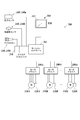
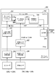
- FIG. 2 is a diagram showing the overall configuration of the control unit 200. As shown in this figure, the control unit 200 is provided with a motion controller 201, a plurality of motor drivers 100A to 100X, a plurality of external sensors 140, and an HMI (Human Machine Interface) 160.
- the plurality of external sensors 140 are sensors that measure and detect information (physical quantities) of each part of the apparatus body 10, and are separate from the sensors (encoders 120A to 120X, etc.) incorporated in the injection molding machine 1 for operation control. belongs to.
- a pressure sensor 140a that measures pressure (force)
- an acceleration sensor 140b that measures acceleration
- a microphone 140c that measures sound are provided as the external sensor 140.
- the plurality of external sensors 140 are arranged in each part of the apparatus main body 10 and are connected to the analog input unit 210 of the motion controller 201 which is a sensor input terminal.
- the motion controller 201 includes a plurality of signal terminals (ports) including those of the analog input unit 210.
- This port includes three types of ports for serial communication, analog signal, and I/O.
- the port for serial communication is used for encoder input, for example.
- the port for analog signal is used, for example, for inputting a tie bar sensor (strain measurement) or a load cell injection pressure.
- the I/O port is used, for example, as a door open/close determination switch or various limit switches.
- a plurality of these three types of ports are provided respectively, and the number is larger than the number normally required for operation control of the apparatus main body 10 (for example, the total number of motors of a general injection molding machine and various measurement amounts).
- the type of the external sensor 140 is not limited to that of the present embodiment, and may include, for example, a gyro sensor or a strain gauge.
- the HMI 160 is an interface for the user to operate the motion controller 201 and acquire various information, and is connected to the motion controller 201.
- the HMI 160 includes a display 161 on which various information is displayed, and an input device (mouse, keyboard, touch panel, etc.; not shown) that receives user operations.
- the interface for the user to operate the motion controller 201 may be provided on the motion controller 201 or the apparatus main body 10, or may be a mobile terminal such as a tablet connected by communication.
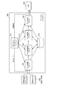
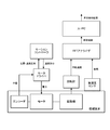
- FIG. 3 is a block diagram showing the control configuration of the motion controller 201. Note that FIG. 3 mainly shows the control configuration of the motion controller 201 for detecting an abnormality of the injection molding machine 1 (apparatus main body 10). As shown in this figure, the motion controller 201 includes an encoder reception circuit 220, an external sensor reception circuit 230, an FPGA (Field Programmable Gate Array) 240, and a microcomputer 250.
- the motion controller 201 includes an encoder reception circuit 220, an external sensor reception circuit 230, an FPGA (Field Programmable Gate Array) 240, and a microcomputer 250.
- FPGA Field Programmable Gate Array
- the encoder reception circuit 220 receives the position signals of the motors 110A to 110X output from the encoders 120A to 120X via the motor drivers 100A to 100X.
- the external sensor receiving circuit 230 receives each measurement signal output from the external sensors 140a to 140c.
- the external sensor reception circuit 230 may be provided for each external sensor 140.
- the FPGA 240 has five functional blocks: a position/speed measurement system 241, an external sensor measurement system 242, a data collection system 243, an abnormality detection system 244, and an output unit 245.
- a CPU Central Processing Unit
- a CPU Central Processing Unit
- the position/speed measurement system 241 acquires information on the speed and position of each motor based on the position signal of each motor received by the encoder reception circuit 220, and uses this speed/position information with the data collection system 243 and motion control. Output to the system 251.
- the external sensor measurement system 242 acquires information on measured physical quantities (acceleration, sound, pressure in the present embodiment) based on the measurement signals from the external sensors 140a to 140c received by the external sensor reception circuit 230, The information of this measurement value is output to the data collection system 243.
- the external sensor measurement system 242 may perform filter processing for removing noise.
- the data collection system 243 collects and accumulates information on measurement values output from the position/speed measurement system 241 and the external sensor measurement system 242.
- the data collection system 243 may collect data at all times until it is operated by the user, or by acquiring an operation signal of the device body 10 based on motion command information from the motion control system 251 as a trigger signal,
- the collection timing (collection start and end timing) may be set according to the operation of the apparatus body 10. Further, the data to be accumulated may be selected from the collected data. For example, only normal operation data and latest data may be stored.
- the abnormality detection system 244 is based on the collected measurement value information (that is, the measurement data of the external sensor 140 and the position/speed information of each motor) and the motion command information that the motion control system 251 has. , The abnormality of the apparatus main body 10 is detected. That is, the abnormality detection system 244 detects the abnormality of the device body 10 based on the measurement data of the external sensor 140 and the control information used for the operation control of the device body 10. In this abnormality detection system 244, it is determined that an abnormality has occurred, for example, when the measured value exceeds a predetermined threshold value (or normal value range). The specific content of the abnormality detection process will be described later.
- the output unit 245 appropriately outputs the abnormality detection result received from the abnormality detection system 244 to an external device or the like. Further, the abnormality detection result may be output to the motion control system 251, so that when an abnormality occurs, the motion control system 251 may limit the torque or speed of each motor.
- an external sensor measurement system 242 that can be referred to as a data input unit that receives a measurement value of the external sensor 140 in the FPGA 240 and an output unit 245 are pre-installed in the FPGA 240.
- the data collection system 243 and the abnormality detection system 244 may be configured so that they can be retrofitted to the FPGA 240.
- the data collection system 243 and the abnormality detection system 244 can be mounted relatively easily by retrofitting, for example, by rewriting a logic circuit in a hardware description language. As a result, it is possible to flexibly respond to a user's request that an abnormality detection function that was initially unnecessary is needed later without requiring major device modification.
- the position/speed measuring system 241 that receives the measured values of the encoders 120A to 120X necessary for motion control be mounted on the FPGA 240 in advance.
- a terminal (analog input unit 210) for connecting the external sensor 140 is also provided in advance, but it may be added later if necessary.
- the external sensor measurement system 242 and the output unit 245 may be mounted in the microcomputer 250 in advance.
- the microcomputer 250 is configured by incorporating hardware such as a CPU, a memory, and a peripheral circuit, integrally controls the motion controller 201, and has a motion control system 251.
- the motion control system 251 generates a speed command for controlling each motor based on the speed/position information of each motor output from the position/speed measurement system 241. When controlling the operation of the apparatus main body 10, this speed command is output to the motor drivers 100A to 100X.
- FIG. 4 is a block diagram for explaining the flow of abnormality detection processing in the motion controller 201.
- the motion controller 201 has four functional blocks of a data collection block 261, a data preprocessing block 262, a data processing block 263, and a data output block 264, as well as a storage device 270 capable of reading and writing various information. I have it.
- the abnormality detection process in the motion controller 201 is executed by a series of processes divided into four functional blocks. As will be described later, the content of processing in each functional block can be easily set by the user through a user interface provided via the HMI 160.
- the data collection block 261 corresponds to the position/velocity measurement system 241, the external sensor measurement system 242, and the data collection system 243, and the data preprocessing block 262 and the data processing block 263 described above.
- the data output block 264 corresponds to the abnormality detection system 244, and corresponds to the output unit 245 described above.
- the data collection block 261 collects necessary data at a set cycle.
- the collected data includes control data from the motion control system 251, position/speed data of each motor from encoders 120A to 120X, which are built-in sensors, acceleration, sound, pressure/force, etc. from the external sensor 140. Further, the motor current, the motor voltage, and the internal temperature may be acquired from the motor drivers 100A to 100X as the data from the built-in sensor.
- the timing at which the process is performed depends on the trigger from the motion control system 251.
- the processing cycle can be set at, for example, 1 ms or 10 ms pitch.
- the data preprocessing block 262 preprocesses data for detecting an abnormality.
- the processing contents here are digital filters (low-pass filter, high-pass filter, band-pass filter, smoothing, etc.), integration, frequency conversion, and custom processing by the user.
- the timing at which the process is performed depends on the trigger from the motion control system 251.
- the processing cycle can be set at, for example, 1 ms or 10 ms pitch.
- the data processing block 263 detects an abnormality by setting a threshold value or the like.
- the processing content here is the setting of the threshold value and the customization setting by the user.
- the failure may be predicted by comparing with a known failure mode, for example.
- the abnormality may be detected by using machine learning.
- the timing at which the process is performed depends on the trigger from the motion control system 251.
- the processing cycle can be set at, for example, 1 ms or 10 ms pitch.
- the data output block 264 outputs the result of data processing. You can select an external device or alarm notification as the output destination. Further, it is possible to output the result to the motion control system 251, and to execute a predetermined operation (stop of the apparatus main body 10, deceleration of each motor, etc.) when an abnormality is detected.
- the timing at which the process is performed depends on the trigger from the motion control system 251.
- the processing cycle can be set at, for example, 1 ms or 10 ms pitch.
- the data to be processed may be written in or read from the storage device 270.
- the data collected by the data collection block 261 may be written to the storage device 270, or the data preprocessing block 262 may process the data and write the processed data to the storage device 270.
- the data may be processed by the data processing block 263 and the processed result may be written to the storage device 270, or the data output block 264 may read and output the result.
- the user can select a simple mode in which the abnormality detection content can be easily set and a detailed mode in which the details can be set by performing a predetermined setting program execution operation from the HMI 160. ing. First, when a new sensor is connected to the port of the analog input unit 210, an address or ID is assigned to this sensor signal based on, for example, a predetermined operation.
- a plurality of tabs corresponding to a plurality of sensor signals connected to the port are displayed, and by operating/selecting the tab, the waveform of the sensor signal corresponding to this tab (for example, a raw waveform) is displayed. Is displayed. The address and ID of the corresponding sensor signal are displayed on the tab.
- the tabs displayed on the display 161 can be selected (added or deleted) as appropriate. Further, a plurality of tabs may be divided into a plurality of pages so that the page to be displayed on the display 161 can be selected.
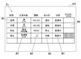
- FIG. 5 is a diagram showing an example of a setting screen in the simple mode.
- the data preprocessing is not performed, and the data processing is determined by the threshold value.
- the microcomputer 250 or the CPU on the FPGA 240 displays the simple setting list Ls on the display 161 of the HMI 160.
- the simple setting list Ls a plurality of abnormality detection points are listed and displayed.
- the contents of each item in the simple setting list Ls except for the status display field B5 can be button-selected by the user, and the selected contents are displayed on the button.
- the section selection button B1, the measurement target selection button B2, the threshold setting button B3, the output destination selection button B4, the status display field B5, and the start/stop button B6 are displayed in the simple setting list Ls.
- the user selects a section of the apparatus body 10 in which the abnormality detection processing is performed.
- selectable sections corresponding to each process of the injection molding machine such as “mold closing” and “mold opening”, are displayed as a drop-down list, and one of them can be selected. It is like this.
- the measurement target selection button B2 the user selects a physical quantity (for example, acceleration, sound, pressure, current, etc.) to be measured.
- that channel number is also selected.
- the terminal channel number of the analog input unit 210 may be simply selected.
- the threshold value setting button B3 the user sets a threshold value for determining abnormality.
- the unit is determined by the physical quantity of the measurement target selected with the measurement target selection button B2.
- the threshold can be arbitrarily set by the user.
- various physical quantities such as a variation per unit time, a temporal average value with respect to a reference level, a variation, and a variation rate can be set as the threshold.
- the output destination selection button B4 is used to select the data output destination when the value of the measurement target exceeds the threshold value, or the operation in that case.
- “notification” for outputting a predetermined alarm display or sound, “stop” for stopping the apparatus body 10, “external” for notifying an external device of abnormality detection, etc. can be selected.
- the output of data or the “notification” may be transmitted to a predetermined terminal, server, or cloud by wired or wireless communication.
- the status display field B5 displays the execution status of the abnormality detection processing. In the present embodiment, one of "monitoring” in which abnormality detection is being performed, “stopping” in which abnormality detection is stopped, and “adjusting” in which abnormality detection cannot be performed due to some cause is displayed.
- start/stop button B6 "START”, “STOP”, and “AUTO” (start of automatic adjustment) are displayed in a drop-down list by a user operation so that start, stop, and automatic adjustment start of the abnormality detection process can be selected. Is becoming However, the selection result is not displayed on the start/stop button B6. Further, the start/stop button B6 changes to a color such as gray when the processing cannot be started due to, for example, adjustment, and the operation is not accepted.
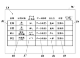
- FIG. 6 is a diagram showing an example of a detailed mode setting screen.
- the microcomputer 250 or the CPU on the FPGA 240 causes the display 161 of the HMI 160 to display the detailed setting list Ld, as shown in FIG.
- a plurality of abnormality detection points are displayed in a list form. Specifically, in the detailed setting list Ld, the same section selection button B1, measurement target selection button B2, output destination selection button B4, status display field B5, start/stop button B6 as in the simple setting list Ls are displayed. A data preprocessing selection button B7 and a data processing selection button B8 are displayed.
- the user selects the content of the data preprocessing (digital filter, integration, frequency conversion, etc.).
- the selected content is displayed on the button.
- the data processing selection button B8 the user selects the content of data processing.
- the content of the data processing can be separately set by the user, for example, an abnormality determination using a threshold value of a predetermined numerical value.
- the selected data processing name is displayed on the button.
- the user can easily detect an abnormality by displaying a GUI (Graphical User Interface) such as the simple setting list Ls or the detailed setting list Ld that receives a user operation on the display 161.
- GUI Graphic User Interface
- the threshold value may be set in a state where the waveform of the sensor signal is displayed on the display 161 of the HMI 160 (that is, during normal operation of the apparatus body 10) so that a threshold line can be set for this waveform. ..
- the threshold value in this case may be arbitrarily set by the user, or may be automatically set according to the numerical value (for example, maximum value) of the sensor signal.
- FIG. 7A are diagrams showing a processing example of vibration data in the abnormality detection processing.
- vibration data that periodically increases is obtained for a rotating device with play.
- the motion controller 201 acquires this vibration data, acquires position/velocity information, and determines a cycle for collecting the vibration data based on this information. Then, when the collected vibration data exceeds a preset threshold value, it is determined that an abnormality has occurred. At this time, as shown in FIG.
- a threshold may be set for a simple time response waveform of the vibration data to detect an abnormality, or as shown in FIG. 7C, frequency analysis of the vibration data is performed. An abnormality may be detected by setting a threshold value for the result.
- frequency analysis may be performed on a raw waveform of vibration subjected to envelope processing (envelope analysis), and a threshold value may be set for the result to detect an abnormality.
- the position (for example, the tip end position) in the moving direction is analyzed.
- Information may be obtained and the vibration response to this position may be viewed. That is, instead of the time response of vibration, analysis may be performed with the position on the horizontal axis. This makes it possible to clarify the correlation between the movement position and the vibration, and further, the correlation between the movement position and the abnormality occurrence timing.
- FIG. 8 is a time chart showing the generation of operation noise in the operation cycle of the injection molding machine 1.
- the mold clamping shaft is a shaft driven by the mold clamping motor 57
- the injection shaft is a shaft driven by the injection motor 86.
- a large operating noise is generated in the sections “mold closing” and “mold opening” in which the mold clamping shaft and the like operate and in the section “injection” in which the injection shaft and the like operates. Occurs.
- the motion controller 201 collects the operation sound data based on the motion command information of the apparatus main body 10 which is held in advance only for the sections “mold closing” and “mold opening” in which the mold clamping axis operates. Then, when the collected driving sound data exceeds a threshold value set in advance for the sections “mold closing” and “mold opening”, it is determined that an abnormality has occurred. In the example of FIG. 8, an abnormality has occurred in the N-th driving sound data.
- the threshold value may be set to a value that is larger by a predetermined value than the normal driving sound stored in advance.
- the motion controller 201 that controls the operation of the injection molding machine 1 (apparatus body 10) collects the data measured by the external sensor 140, and the measured data and the apparatus body 10 are collected.
- the abnormality of the apparatus main body 10 is detected based on the control information for the operation control. That is, it is possible to detect the abnormality of the device body 10 by using the control information (position/speed information of each motor and motion command information) that the motion controller 201 has to control the device body 10.
- the control information position/speed information of each motor and motion command information
- the abnormality of the injection molding machine 1 (apparatus body 10) whose operation is controlled by the motion controller 201 can be easily detected. Further, by using the motion command information, it is possible to more easily perform the abnormality detection process, for example, by using this information as a trigger to collect data.
- an external sensor measurement system 242 that is an input unit that receives a measurement signal from the external sensor 140 and an output unit 245 that outputs an abnormality detection result by the abnormality detection system 244 are pre-installed in the FPGA 240, and the data collection system 243 and The abnormality detection system 244 may be configured to be retrofittable to the FPGA 240 (or the microcomputer 250). With this configuration, the abnormality detection processing by the data collection system 243 and the abnormality detection system 244 can be relatively easily constructed even afterward. As a result, it is possible to flexibly respond to a user's request that an abnormality detection function, which is initially unnecessary, is needed later without a major device modification.
- the data collection system 243 and the abnormality detection system 244 are installed in the FPGA 240 instead of the microcomputer 250 in which the motion control system 251 is installed. Thereby, the abnormality detection processing by the data collection system 243 and the abnormality detection system 244 can be realized without affecting the motion control of the injection molding machine 1.
- the data collection timing can be set by the trigger signal based on the motion command information, so the user can easily set the data collection timing.
- the HMI 160 can be connected to the motion controller 201, and a display screen 161 of the HMI 160 displays a setting screen (simple setting list Ls or detailed setting list Ld) for setting the abnormality detection content based on a user operation. It has become so. Thus, the user can easily set the abnormality detection content by using the setting screen which is the GUI.
- a setting screen simple setting list Ls or detailed setting list Ld
- the present invention is not limited to the above embodiments.
- the data collection system 243 and the abnormality detection system 244 are mounted on the FPGA 240.
- the data collection system 243 and the abnormality detection system 244 may be mounted on the microcomputer 250 instead of the FPGA 240.
- the data collection system 243 may receive the position/velocity information from the motion control system 251.
- the data collection system 243 and the abnormality detection system 244 may be configured so that they can be mounted on the microcomputer 250 later.
- the data collection system 243 and the abnormality detection system 244 are prepared as functions for data collection, data preprocessing, and data processing described in, for example, C language and installed in the microcomputer 250, so that they can be installed later. But it can be implemented relatively easily.
- the external sensor measurement system 242 and the output unit 245 may be mounted on the microcomputer 250.
- the injection molding machine 1 (apparatus main body 10) has been described as the mechanical device whose operation is controlled by the motion controller 201, but the mechanical device may be a molding machine other than the injection molding machine. .. Furthermore, the present invention can be widely applied to mechanical devices other than the molding machine, such as a press machine and a rolling machine, as long as the operation is controlled by the motion controller. In addition, the details shown in the embodiment can be appropriately changed without departing from the spirit of the invention.
- the motion controller and the molding machine according to the present invention are useful for detecting an abnormality in a mechanical device whose operation is controlled by the motion controller.
- Injection Molding Machine 10 Device Main Body 11 Injection Device 12 Mold Clamping Device 43 Mold Device 100A-100X Motor Driver 110A-110X Motor 120A-120X Encoder 140 External Sensor 160 HMI 161 Display 200 Control unit 201 Motion controller 210 Analog input unit 220 Encoder receiving circuit 230 External sensor receiving circuit 240 FPGA 241 Position/velocity measurement system 242 External sensor measurement system 243 Data collection system 244 Abnormality detection system 245 Output unit 250 Microcomputer 251 Motion control system 261 Data collection block 262 Data pre-processing block 263 Data processing block 264 Data output block 270 Storage device B1 section Selection button B2 Measurement target selection button B3 Threshold setting button B4 Output destination selection button B5 Status display field B6 Start/Stop button B7 Data pre-processing selection button B8 Data processing selection button Ld Detailed setting list Ls Simple setting list Ls Simple setting list Ls Simple setting list
Landscapes
- Engineering & Computer Science (AREA)
- Manufacturing & Machinery (AREA)
- Mechanical Engineering (AREA)
- Human Computer Interaction (AREA)
- Physics & Mathematics (AREA)
- General Physics & Mathematics (AREA)
- Automation & Control Theory (AREA)
- Injection Moulding Of Plastics Or The Like (AREA)
- Testing And Monitoring For Control Systems (AREA)
Abstract
Description
加速度センサにより計測された振動データは、回転計で検出した回転数を用いてFFT(Fast Fourier transform)アナライザで周波数解析などされる。そして、この解析結果に基づいて、パソコンなどの演算装置や人間が、機械装置に異常が発生しているか否かを判定する。
前記機械装置に設置した外部センサにより計測されたデータを収集するデータ収集部と、
前記データ収集部により収集された計測データ、及び、前記機械装置の動作制御に用いる制御情報に基づいて、前記機械装置の異常を検知する異常検知部と、
を備える構成とした。
成形材料を射出する射出装置と、成形材料が充填される金型装置を動かす型締装置とを有する装置本体と、
前記射出装置及び前記型締装置を駆動する各モータの動作を制御するモーションコントローラと、
を備える成形装置であって、
前記モーションコントローラは、
前記装置本体に設置した外部センサにより計測されたデータを収集するデータ収集部と、
前記データ収集部により収集された計測データ、及び、前記装置本体の動作制御に用いる制御情報に基づいて、前記装置本体の異常を検知する異常検知部と、
を備える構成とした。
図1は、本実施形態における射出成形機1を示す図である。
この図に示すように、本実施形態における射出成形機1は、当該射出成形機1の装置本体10と、装置本体10を制御するための制御ユニット200とを備えている。なお、図1では、制御ユニット200の概略構成を示している。
なお、以下では、型締用モータ57、射出用モータ86、計量用モータ83、可塑化移動用モータ22、エジェクト用モータ72を、第1モータ110A~第nモータ110Xと記載する。
制御ユニット200は、モーションコントローラ201と、複数のモータドライバ100A~100Xとを備えている。
モーションコントローラ201は、射出成形機1(装置本体10)の動作を制御するものである。具体的に、モーションコントローラ201は、所定の制御プログラムに従って射出成形機1の複数のモータドライバ100A~100Xにモーション指令(具体的には速度指令)を出力する。モーション指令とは、射出成形機1(装置本体10)の動作を制御するための制御指令であって、射出や型締めなどの各工程の順番や作業時間といった、射出成形機1の一連の動作の情報を含むものである。モーションコントローラ201の詳細な制御構成については後述する。
複数のモータドライバ100A~100Xは、モーションコントローラ201からのモーション指令に基づいて、第1モータ110A~第nモータ110Xの各々に電力を出力し、これら各モータを駆動する。また、モータドライバ100A~100Xは、各モータの位置・速度応答の情報を、第1モータ110A~第nモータ110Xの位置を検出するエンコーダ120A~120X(図2参照)から取得し、モーションコントローラ201に出力する。
これらにより、射出成形機1の各部が連携して動作し、所定の成形処理が実行される。
なお、図1では、モーションコントローラ201がモータドライバ100A~100Xをシリアル制御する状態を示しているが、モーションコントローラ201がモータドライバ100A~100Xと個別に通信するパラレル制御を行うこととしてもよい。
図2は、制御ユニット200の全体構成を示す図である。
この図に示すように、制御ユニット200には、モーションコントローラ201及び複数のモータドライバ100A~100Xのほか、複数の外部センサ140と、HMI(Human Machine Interface)160とが設けられている。
モーションコントローラ201は、アナログ入力ユニット210のものも含め、複数の信号端子(ポート)を備える。このポートは、シリアル通信用、アナログ信号用、I/O用の3種類のものを含む。シリアル通信用のポートは、例えばエンコーダ入力に用いられる。アナログ信号用のポートは、例えばタイバーセンサ(ひずみ計測)やロードセル射出圧の入力に用いられる。I/O用のポートは、例えばドア開閉判断用スイッチや各種リミットスイッチ等に用いられる。これら3種類のポートは、それぞれ複数設けられ、装置本体10の動作制御に通常必要な数量(例えば、一般的な射出成形機のモータ数や計測諸量の合計)よりも多く設けられる。
なお、外部センサ140の種別は、本実施形態のものに限定されず、例えばジャイロセンサや歪ゲージなどを含んでいてもよい。
なお、ユーザがモーションコントローラ201を操作等するためのインターフェースは、モーションコントローラ201又は装置本体10に設けられたものでもよいし、通信接続されたタブレットなどの携帯端末であってもよい。
図3は、モーションコントローラ201の制御構成を示すブロック図である。なお、図3では、主に射出成形機1(装置本体10)の異常を検知するためのモーションコントローラ201の制御構成を示している。
この図に示すように、モーションコントローラ201は、エンコーダ受信回路220と、外部センサ受信回路230と、FPGA(Field Programmable Gate Array)240と、マイコン250とを備えて構成されている。
外部センサ受信回路230は、外部センサ140a~140cから出力されたそれぞれの計測信号を受け付ける。この外部センサ受信回路230は、外部センサ140ごとに設けられていてもよい。
外部センサ計測システム242は、外部センサ受信回路230が受信した外部センサ140a~140cからの計測信号に基づいて、計測された物理量(本実施形態では、加速度、音、圧力)の情報を取得し、この計測値の情報をデータ収集システム243に出力する。外部センサ計測システム242では、ノイズを除去するフィルタ処理を行うこととしてもよい。
出力部245は、異常検知システム244から受けた異常検知結果を、外部機器などに適宜出力する。また、異常検知結果をモーションコントロールシステム251にも出力することとし、異常が発生した場合に、モーションコントロールシステム251が各モータのトルクや速度を制限するようにしてもよい。
モーションコントロールシステム251は、位置・速度計測システム241から出力された各モータの速度・位置情報に基づいて、各モータを制御するための速度指令を生成する。装置本体10を動作制御する場合には、この速度指令がモータドライバ100A~100Xに出力される。
続いて、ユーザによる異常検知内容の設定について説明する。
図4は、モーションコントローラ201における異常検知処理の流れを説明するためのブロック図である。
なお、4つの機能ブロックのうち、データ収集ブロック261が上述の位置・速度計測システム241と外部センサ計測システム242とデータ収集システム243に対応し、データ前処理ブロック262及びデータ処理ブロック263が上述の異常検知システム244に対応し、データ出力ブロック264が上述の出力部245に対応している。
収集されるデータは、モーションコントロールシステム251からの制御データ、内蔵センサであるエンコーダ120A~120Xからの各モータの位置・速度データ、外部センサ140からの加速度、音、圧力/力などである。また、内蔵センサからのデータとして、モータドライバ100A~100Xからモータ電流、モータ電圧、内部温度を取得できるようにしてもよい。
処理を行うタイミングは、モーションコントロールシステム251からのトリガによる。
処理を行う周期は、例えば、1ms、10msピッチなどで設定可能である。
ここでの処理内容は、デジタルフィルタ(ローパスフィルタ、ハイパスフィルタ、バンドパスフィルタ、平滑化など)、積算、周波数変換や、ユーザによるカスタム処理である。
処理を行うタイミングは、モーションコントロールシステム251からのトリガによる。
処理を行う周期は、例えば、1ms、10msピッチなどで設定可能である。
ここでの処理内容は、閾値の設定や、ユーザによるカスタマイズ設定である。カスタマイズ設定では、例えば既知の故障モードとの比較などにより、故障の予測を行うこととしてもよい。また、機械学習を用いて異常を検知できるようにしてもよい。
処理を行うタイミングは、モーションコントロールシステム251からのトリガによる。
処理を行う周期は、例えば、1ms、10msピッチなどで設定可能である。
出力先には、外部機器やアラーム通知などを選択できる。また、モーションコントロールシステム251に結果を出力して、異常が検知された場合に所定の動作(装置本体10の停止や各モータの減速など)を実行させることができる。
処理を行うタイミングは、モーションコントロールシステム251からのトリガによる。
処理を行う周期は、例えば、1ms、10msピッチなどで設定可能である。
続いて、上述した異常検知内容の設定について、具体例を挙げて説明する。
本実施形態のモーションコントローラ201では、ユーザがHMI160から所定の設定プロブラムの実行操作を行うことにより、異常検知内容を簡便に設定できる簡易モードと、詳細に設定できる詳細モードとを選択できるようになっている。
まず、アナログ入力ユニット210のポートに新たなセンサが接続されると、例えば所定の操作に基づいて、このセンサ信号にアドレスやIDが割り振られる。HMI160のディスプレイ161上には、ポートに接続された複数のセンサ信号に対応した複数のタブが表示され、タブを操作・選択することでこのタブに対応したセンサ信号の波形(例えば生波形)が表示される。タブ上には、対応するセンサ信号のアドレスやIDが表示される。ディスプレイ161上に表示させるタブは適宜選択(追加や削除)できる。また、複数のタブが複数のページに分割され、ディスプレイ161上に表示させるページを選択できるようにしてもよい。
図5は、簡易モードの設定画面例を示す図である。
簡易モードでは、データ前処理は行われず、データ処理は閾値による判定となっている。
ユーザが簡易モードを選択すると、図5に示すように、マイコン250(又はFPGA240上のCPU)が、簡易設定リストLsをHMI160のディスプレイ161に表示させる。
具体的に、簡易設定リストLsには、区間選択ボタンB1、計測対象選択ボタンB2、閾値設定ボタンB3、出力先選択ボタンB4、状態表示欄B5、開始・停止ボタンB6が表示される。
計測対象選択ボタンB2では、ユーザが計測対象の物理量(例えば、加速度、音、圧力、電流など)を選択する。同じ区間の同じ計測対象が複数ある場合には、そのチャンネル番号も選択する。なお、ここでは、単にアナログ入力ユニット210の端子ch番号を選択することとしてもよい。
閾値設定ボタンB3では、ユーザが、異常と判定する閾値を設定する。単位は計測対象選択ボタンB2で選択した計測対象の物理量によって決まる。閾値はユーザが任意に設定できる。閾値には、単なるレベルではなく、単位時間当たりの変動量、基準レベルに対する時間的平均値、変化量、変化率等の様々な物理量を設定できる。
状態表示欄B5には、異常検知処理の実行状態が表示される。本実施形態では、異常検知を実行している「監視中」、異常検知を停止している「停止中」、何らかの要因により異常検知を行えない「調整中」の、いずれかが表示される。
開始・停止ボタンB6では、ユーザ操作により「START」、「STOP」、「AUTO」(自動調整開始)がドロップダウンリストで表示され、異常検知処理の開始、停止、自動調整開始を選択できるようになっている。ただし、この選択結果は開始・停止ボタンB6上には表示されない。また、開始・停止ボタンB6は、例えば調整中などのために処理を開始できない場合に、色がグレーなどに変わり、操作を受け付けない状態となる。
図6は、詳細モードの設定画面例を示す図である。
ユーザが詳細モードを選択すると、図6に示すように、マイコン250(又はFPGA240上のCPU)が、詳細設定リストLdをHMI160のディスプレイ161に表示させる。
具体的に、詳細設定リストLdには、簡易設定リストLsと同様の区間選択ボタンB1、計測対象選択ボタンB2、出力先選択ボタンB4、状態表示欄B5、開始・停止ボタンB6が表示されるほか、データ前処理選択ボタンB7と、データ処理選択ボタンB8とが表示される。
データ処理選択ボタンB8では、ユーザがデータ処理の内容を選択する。データ処理の内容は、例えば所定の数値の閾値による異常判定などが、ユーザにより別途設定できるようになっている。選択されたデータ処理名がボタン上に表示される。
なお、閾値の設定は、HMI160のディスプレイ161上にセンサ信号の波形を表示させた状態で(すなわち装置本体10の正常運転時に)、この波形に対して閾値のラインを設定できるようにしてもよい。この場合の閾値は、ユーザが任意に設定できてもよいし、センサ信号の数値(例えば最大値)に応じて自動で設定されてもよい。
続いて、異常検知処理を実行する際のモーションコントローラ201の動作について、具体例を示して説明する。
まず、モータなどの回転機器のガタによる振動を加速度センサ140bで検出して、異常を検知する場合について説明する。
図7A~図7Dは、異常検知処理における振動データの処理例を示す図である。
図7Aに示すように、ガタのある回転機器では、周期的に大きくなる振動データが得られる。
モーションコントローラ201では、この振動データを取得するとともに、位置・速度情報を取得し、この情報に基づいて振動データを収集する周期を決定する。
そして、収集した振動データが、予め設定された閾値を超えた場合に、異常が発生したと判定する。このとき、図7Bに示すように、振動データの単純な時間応答波形に対して閾値を設定して異常を検知してもよいし、図7Cに示すように、振動データの周波数解析を行い、その結果に対する閾値を設定して異常を検知してもよい。あるいは、図7A、Dに示すように、振動の生波形を包絡線処理(エンベロープ解析)したものに対して周波数解析を行い、その結果に対する閾値を設定して異常を検知してもよい。
これにより、移動位置と振動との相関、ひいては移動位置と異常発生タイミングとの相関を、明らかにすることができる。
次に、射出成形機1の特定の軸(例えば型締軸)の動作音をマイクロホン140cで検出して、異常を検知する場合について説明する。
図8は、射出成形機1の作動サイクルにおける運転音の発生を示すタイムチャートである。なお、型締軸とは型締用モータ57により駆動される軸であり、射出軸とは射出用モータ86により駆動される軸である。
この図に示すように、射出成形機1を作動させると、型締軸等が動作する区間「型閉」、「型開」や、射出軸等が動作する区間「射出」において、大きな運転音が発生する。
モーションコントローラ201では、予め持っている装置本体10のモーション指令情報に基づいて、型締軸が動作する区間「型閉」と「型開」のみを対象として、運転音データを収集する。
そして、収集した運転音データが、この区間「型閉」と「型開」に対して予め設定された閾値を超えた場合に、異常が発生したと判定する。図8の例では、N回目の運転音データにおいて異常が発生している。なお、閾値は、予め保存しておいた正常時の運転音よりも所定値だけ大きい値として設定してもよい。
以上のように、本実施形態によれば、射出成形機1(装置本体10)の動作を制御するモーションコントローラ201が、外部センサ140により計測されたデータを収集し、この計測データと装置本体10の動作制御用の制御情報とに基づいて、装置本体10の異常を検知する。
すなわち、装置本体10を制御するためにモーションコントローラ201が持っている制御情報(各モータの位置・速度情報やモーション指令情報)を利用して、装置本体10の異常検知を行うことができる。これにより、FFTアナライザや回転計などの計測専用の機器を必要であった従来と異なり、モーションコントローラ201に外部センサ140を接続するだけで、装置本体10の異常検知を行うことができる。
したがって、モーションコントローラ201により動作制御される射出成形機1(装置本体10)の異常検知を、簡便に行うことができる。また、モーション指令情報を利用することで、例えばこの情報をトリガとしてデータ収集を実行するなどして、より容易に異常検知処理を行うことができる。
このように構成することにより、データ収集システム243と異常検知システム244による異常検知処理を、後からでも比較的簡便に構築することができる。ひいては、例えば当初は不要とした異常検知機能が後から必要になったといったユーザの要望などにも、大掛かりな装置改造を伴うことなく柔軟に対応することができる。
これにより、射出成形機1のモーションコントロールに影響を及ぼすことなく、データ収集システム243及び異常検知システム244による異常検知処理を実現することができる。
これにより、ユーザは、GUIである設定画面を利用して簡単に異常検知内容を設定することができる。
以上、本発明の各実施の形態について説明したが、本発明は上記の実施の形態に限られない。
例えば上記実施例では、モーションコントローラ201において、データ収集システム243及び異常検知システム244がFPGA240上に実装されていることとした。しかし、図9に示すように、データ収集システム243及び異常検知システム244は、FPGA240でなく、マイコン250上に実装されていてもよい。この場合、データ収集システム243は、モーションコントロールシステム251から位置・速度情報を受け取ることとすればよい。
また、この構成の場合でも、データ収集システム243及び異常検知システム244は、後付けでマイコン250上に実装可能なように構成されていればよい。これらデータ収集システム243と異常検知システム244は、例えばC言語などで記述されたデータ収集やデータ前処理、データ処理についての関数として準備しておき、これをマイコン250にインストールすることで、後からでも比較的簡単に実装することができる。なお、外部センサ計測システム242と出力部245は、マイコン250に実装されていてもよい。
その他、実施の形態で示した細部は、発明の趣旨を逸脱しない範囲で適宜変更可能である。
10 装置本体
11 射出装置
12 型締装置
43 金型装置
100A~100X モータドライバ
110A~110X モータ
120A~120X エンコーダ
140 外部センサ
160 HMI
161 ディスプレイ
200 制御ユニット
201 モーションコントローラ
210 アナログ入力ユニット
220 エンコーダ受信回路
230 外部センサ受信回路
240 FPGA
241 位置・速度計測システム
242 外部センサ計測システム
243 データ収集システム
244 異常検知システム
245 出力部
250 マイコン
251 モーションコントロールシステム
261 データ収集ブロック
262 データ前処理ブロック
263 データ処理ブロック
264 データ出力ブロック
270 記憶装置
B1 区間選択ボタン
B2 計測対象選択ボタン
B3 閾値設定ボタン
B4 出力先選択ボタン
B5 状態表示欄
B6 開始・停止ボタン
B7 データ前処理選択ボタン
B8 データ処理選択ボタン
Ld 詳細設定リスト
Ls 簡易設定リスト
Claims (11)
- 機械装置の動作を制御するモーションコントローラであって、
前記機械装置に設置した外部センサにより計測されたデータを収集するデータ収集部と、
前記データ収集部により収集された計測データ、及び、前記機械装置の動作制御に用いる制御情報に基づいて、前記機械装置の異常を検知する異常検知部と、
を備える、
モーションコントローラ。 - マイコンとFPGAとを備え、
前記FPGAには、当該FPGA上に前記外部センサによる計測信号を受け付ける入力部と、前記異常検知部による異常検知結果を出力する出力部とが予め実装され、
前記データ収集部及び前記異常検知部は、前記マイコン又は前記FPGAに、後付けで実装可能に構成されている、
請求項1記載のモーションコントローラ。 - マイコンとFPGAとを備え、
前記マイコンには、モーション指令を生成するモーション制御部が実装され、
前記FPGAには、前記データ収集部及び前記異常検知部が実装されている、
請求項1又は請求項2に記載のモーションコントローラ。 - 前記制御情報は、前記機械装置を駆動するモータの位置情報及び速度情報と、前記機械装置に対するモーション指令情報とを含み、
前記モータの位置情報及び速度情報は、当該モータに設けられたエンコーダからの信号に基づいて取得される、
請求項1から請求項3の何れか一項に記載のモーションコントローラ。 - 前記データ収集部は、前記モーション指令情報に基づくトリガ信号によって、データ収集タイミングを設定する、
請求項4記載のモーションコントローラ。 - 表示部を有する機器と接続可能に構成され、
ユーザ操作に基づいて異常検知内容を設定する設定画面を前記表示部に表示させる表示制御手段を備える、
請求項1から請求項5の何れか一項に記載のモーションコントローラ。 - 前記外部センサは、加速度センサ、マイクロホン、圧力センサ、ジャイロセンサ及び歪ゲージのうち少なくとも1つを含む、
請求項1から請求項6の何れか一項に記載のモーションコントローラ。 - シリアル通信用、アナログ信号用及びI/O用を含む複数の信号端子を備える、
請求項1から請求項7の何れか一項に記載のモーションコントローラ。 - 前記複数の信号端子は、前記機械装置の動作制御に通常必要な数量よりも多い、
請求項8に記載のモーションコントローラ。 - 前記外部センサが接続される信号端子と、
前記信号端子に入力される前記外部センサの信号波形を表示する表示手段と、
ユーザ操作に基づいて、前記外部センサの信号に対する異常判定用の閾値を前記表示手段上で設定する設定手段と、を備える、
請求項1から請求項9の何れか一項に記載のモーションコントローラ。 - 成形材料を射出する射出装置と、成形材料が充填される金型装置を動かす型締装置とを有する装置本体と、
前記射出装置及び前記型締装置を駆動する各モータの動作を制御するモーションコントローラと、
を備える成形装置であって、
前記モーションコントローラは、
前記装置本体に設置した外部センサにより計測されたデータを収集するデータ収集部と、
前記データ収集部により収集された計測データ、及び、前記装置本体の動作制御に用いる制御情報に基づいて、前記装置本体の異常を検知する異常検知部と、
を備える、
成形機。
Priority Applications (3)
| Application Number | Priority Date | Filing Date | Title |
|---|---|---|---|
| KR1020217020397A KR102727816B1 (ko) | 2019-01-07 | 2020-01-07 | 모션컨트롤러 및 성형기 |
| JP2020565149A JP7399108B2 (ja) | 2019-01-07 | 2020-01-07 | モーションコントローラ |
| CN202080008247.1A CN113302032A (zh) | 2019-01-07 | 2020-01-07 | 运动控制器及成型机 |
Applications Claiming Priority (2)
| Application Number | Priority Date | Filing Date | Title |
|---|---|---|---|
| JP2019000496 | 2019-01-07 | ||
| JP2019-000496 | 2019-01-07 |
Publications (1)
| Publication Number | Publication Date |
|---|---|
| WO2020145247A1 true WO2020145247A1 (ja) | 2020-07-16 |
Family
ID=71521643
Family Applications (1)
| Application Number | Title | Priority Date | Filing Date |
|---|---|---|---|
| PCT/JP2020/000099 Ceased WO2020145247A1 (ja) | 2019-01-07 | 2020-01-07 | モーションコントローラ及び成形機 |
Country Status (4)
| Country | Link |
|---|---|
| JP (1) | JP7399108B2 (ja) |
| KR (1) | KR102727816B1 (ja) |
| CN (1) | CN113302032A (ja) |
| WO (1) | WO2020145247A1 (ja) |
Cited By (3)
| Publication number | Priority date | Publication date | Assignee | Title |
|---|---|---|---|---|
| CN113942203A (zh) * | 2020-07-17 | 2022-01-18 | 伊之密精密机械(苏州)有限公司 | 震动自适应调节方法及注塑机 |
| WO2023053544A1 (ja) * | 2021-09-29 | 2023-04-06 | オムロン株式会社 | 制御システム |
| CN119773175A (zh) * | 2025-01-15 | 2025-04-08 | 广州中和互联网技术有限公司 | 一种自适应全自动样条注塑系统 |
Families Citing this family (1)
| Publication number | Priority date | Publication date | Assignee | Title |
|---|---|---|---|---|
| KR102682654B1 (ko) * | 2022-05-02 | 2024-07-09 | 주식회사 이몰디노 | 성형 제품의 품질 관리를 위한 센싱장치 |
Citations (7)
| Publication number | Priority date | Publication date | Assignee | Title |
|---|---|---|---|---|
| JPH10249901A (ja) * | 1997-03-18 | 1998-09-22 | Toyo Mach & Metal Co Ltd | 成形機の型締め制御方法 |
| US20050129794A1 (en) * | 2003-12-12 | 2005-06-16 | Chin-Yu Chao | Servo motor control apparatus for electric injection molding machine |
| JP2012516175A (ja) * | 2009-01-30 | 2012-07-19 | レイン アプライド ダイアノスティクス リミテッド | 信号サンプルトリガー装置、データ収集システムおよびアナログ信号をサンプリングする方法 |
| JP2013022842A (ja) * | 2011-07-21 | 2013-02-04 | Nissei Plastics Ind Co | 射出成形機の波形モニタ装置 |
| WO2015133175A1 (ja) * | 2014-03-04 | 2015-09-11 | オムロン株式会社 | 制御システム、制御装置および制御方法 |
| JP2016101643A (ja) * | 2014-11-28 | 2016-06-02 | 株式会社安川電機 | ブレーキ診断装置及びブレーキ診断方法 |
| JP2018166378A (ja) * | 2017-03-28 | 2018-10-25 | 住友重機械工業株式会社 | モータ駆動システムおよび射出成形機 |
Family Cites Families (5)
| Publication number | Priority date | Publication date | Assignee | Title |
|---|---|---|---|---|
| JPH05157662A (ja) | 1991-12-04 | 1993-06-25 | Sumitomo Heavy Ind Ltd | 射出成形機の故障診断方法及び故障診断装置 |
| JP2003181900A (ja) * | 2001-12-20 | 2003-07-02 | Omron Corp | コントローラ並びにモーション制御装置 |
| JP6348161B2 (ja) * | 2016-11-29 | 2018-06-27 | ファナック株式会社 | 射出成形機の制御装置及び管理システム |
| JP6781612B2 (ja) | 2016-12-02 | 2020-11-04 | 大成建設株式会社 | シールドマシンの劣化診断方法 |
| JP6399136B1 (ja) * | 2017-03-31 | 2018-10-03 | オムロン株式会社 | 制御装置、制御プログラム、および制御システム |
-
2020
- 2020-01-07 WO PCT/JP2020/000099 patent/WO2020145247A1/ja not_active Ceased
- 2020-01-07 KR KR1020217020397A patent/KR102727816B1/ko active Active
- 2020-01-07 CN CN202080008247.1A patent/CN113302032A/zh active Pending
- 2020-01-07 JP JP2020565149A patent/JP7399108B2/ja active Active
Patent Citations (7)
| Publication number | Priority date | Publication date | Assignee | Title |
|---|---|---|---|---|
| JPH10249901A (ja) * | 1997-03-18 | 1998-09-22 | Toyo Mach & Metal Co Ltd | 成形機の型締め制御方法 |
| US20050129794A1 (en) * | 2003-12-12 | 2005-06-16 | Chin-Yu Chao | Servo motor control apparatus for electric injection molding machine |
| JP2012516175A (ja) * | 2009-01-30 | 2012-07-19 | レイン アプライド ダイアノスティクス リミテッド | 信号サンプルトリガー装置、データ収集システムおよびアナログ信号をサンプリングする方法 |
| JP2013022842A (ja) * | 2011-07-21 | 2013-02-04 | Nissei Plastics Ind Co | 射出成形機の波形モニタ装置 |
| WO2015133175A1 (ja) * | 2014-03-04 | 2015-09-11 | オムロン株式会社 | 制御システム、制御装置および制御方法 |
| JP2016101643A (ja) * | 2014-11-28 | 2016-06-02 | 株式会社安川電機 | ブレーキ診断装置及びブレーキ診断方法 |
| JP2018166378A (ja) * | 2017-03-28 | 2018-10-25 | 住友重機械工業株式会社 | モータ駆動システムおよび射出成形機 |
Non-Patent Citations (1)
| Title |
|---|
| WOLF, WAYNE: "COMPUTERS AS COMPONENTS", part 9.8.1 16 March 2009, article "Principles of Embedded Computer System Design", pages: 572 - 577 * |
Cited By (6)
| Publication number | Priority date | Publication date | Assignee | Title |
|---|---|---|---|---|
| CN113942203A (zh) * | 2020-07-17 | 2022-01-18 | 伊之密精密机械(苏州)有限公司 | 震动自适应调节方法及注塑机 |
| CN113942203B (zh) * | 2020-07-17 | 2023-12-29 | 伊之密精密机械(苏州)有限公司 | 震动自适应调节方法及注塑机 |
| WO2023053544A1 (ja) * | 2021-09-29 | 2023-04-06 | オムロン株式会社 | 制御システム |
| JP2023049535A (ja) * | 2021-09-29 | 2023-04-10 | オムロン株式会社 | 制御システム |
| JP7739906B2 (ja) | 2021-09-29 | 2025-09-17 | オムロン株式会社 | 制御システム |
| CN119773175A (zh) * | 2025-01-15 | 2025-04-08 | 广州中和互联网技术有限公司 | 一种自适应全自动样条注塑系统 |
Also Published As
| Publication number | Publication date |
|---|---|
| JPWO2020145247A1 (ja) | 2021-11-25 |
| JP7399108B2 (ja) | 2023-12-15 |
| KR102727816B1 (ko) | 2024-11-07 |
| KR20210111253A (ko) | 2021-09-10 |
| CN113302032A (zh) | 2021-08-24 |
Similar Documents
| Publication | Publication Date | Title |
|---|---|---|
| JP7399108B2 (ja) | モーションコントローラ | |
| US6527534B1 (en) | Ejector controller of injection molding machine | |
| JP6975188B2 (ja) | 状態判定装置及び状態判定方法 | |
| JP7010861B2 (ja) | 状態判定装置及び状態判定方法 | |
| JP2002172670A (ja) | 射出成形機の異物検出方法 | |
| CN110962316B (zh) | 状态判断装置以及状态判断方法 | |
| JP2020066178A (ja) | 状態判定装置及び状態判定方法 | |
| US11150636B2 (en) | State determination device and state determination method | |
| JP2003200456A (ja) | 射出成形機の表示装置及び射出成形機 | |
| US11772312B2 (en) | State determination device and state determination method for determining operation state of injection molding machine | |
| CN100548621C (zh) | 具有装设存储介质检测器的注射成形机 | |
| CN103900904B (zh) | 一种中子原位力学加载系统 | |
| JP7011106B1 (ja) | 状態判定装置及び状態判定方法 | |
| CN117795308A (zh) | 控制装置以及控制方法 | |
| CN112805669A (zh) | 测量物理测量参量的方法和执行该方法的测量系统 | |
| JP2005343029A (ja) | 成形機の監視表示方法 | |
| JP7184997B2 (ja) | 状態判定装置及び状態判定方法 | |
| JP4405855B2 (ja) | 成形機の監視表示方法 | |
| KR100820677B1 (ko) | 로터리 엔코더 점검 장치 | |
| KR101408247B1 (ko) | 양방향 통신이 가능한 앵글시퀀스가 구비된 피엘씨 컨트롤러 | |
| JP2006297603A (ja) | 成形機及びその監視表示方法 | |
| JP4982273B2 (ja) | 成形機のデータ表示方法 | |
| JP2013111892A (ja) | 射出成形機のトラブルシューティング方法 | |
| WO2024004106A1 (ja) | 判定システム及び方法 | |
| KR20130123738A (ko) | 양방향 통신이 가능한 앵글시퀀스가 구비된 피엘씨 컨트롤러 |
Legal Events
| Date | Code | Title | Description |
|---|---|---|---|
| 121 | Ep: the epo has been informed by wipo that ep was designated in this application |
Ref document number: 20737959 Country of ref document: EP Kind code of ref document: A1 |
|
| ENP | Entry into the national phase |
Ref document number: 20217020397 Country of ref document: KR Kind code of ref document: A |
|
| ENP | Entry into the national phase |
Ref document number: 2020565149 Country of ref document: JP Kind code of ref document: A |
|
| NENP | Non-entry into the national phase |
Ref country code: DE |
|
| 122 | Ep: pct application non-entry in european phase |
Ref document number: 20737959 Country of ref document: EP Kind code of ref document: A1 |