WO2020138450A1 - Matériau d'acier apte à être utilisé comme matière première pour composant de palier carbonitruré - Google Patents
Matériau d'acier apte à être utilisé comme matière première pour composant de palier carbonitruré Download PDFInfo
- Publication number
- WO2020138450A1 WO2020138450A1 PCT/JP2019/051503 JP2019051503W WO2020138450A1 WO 2020138450 A1 WO2020138450 A1 WO 2020138450A1 JP 2019051503 W JP2019051503 W JP 2019051503W WO 2020138450 A1 WO2020138450 A1 WO 2020138450A1
- Authority
- WO
- WIPO (PCT)
- Prior art keywords
- content
- steel material
- carbides
- less
- bearing component
- Prior art date
Links
Images

Classifications
-
- C—CHEMISTRY; METALLURGY
- C22—METALLURGY; FERROUS OR NON-FERROUS ALLOYS; TREATMENT OF ALLOYS OR NON-FERROUS METALS
- C22C—ALLOYS
- C22C38/00—Ferrous alloys, e.g. steel alloys
- C22C38/18—Ferrous alloys, e.g. steel alloys containing chromium
- C22C38/40—Ferrous alloys, e.g. steel alloys containing chromium with nickel
- C22C38/46—Ferrous alloys, e.g. steel alloys containing chromium with nickel with vanadium
-
- C—CHEMISTRY; METALLURGY
- C21—METALLURGY OF IRON
- C21D—MODIFYING THE PHYSICAL STRUCTURE OF FERROUS METALS; GENERAL DEVICES FOR HEAT TREATMENT OF FERROUS OR NON-FERROUS METALS OR ALLOYS; MAKING METAL MALLEABLE, e.g. BY DECARBURISATION OR TEMPERING
- C21D1/00—General methods or devices for heat treatment, e.g. annealing, hardening, quenching or tempering
- C21D1/06—Surface hardening
-
- C—CHEMISTRY; METALLURGY
- C21—METALLURGY OF IRON
- C21D—MODIFYING THE PHYSICAL STRUCTURE OF FERROUS METALS; GENERAL DEVICES FOR HEAT TREATMENT OF FERROUS OR NON-FERROUS METALS OR ALLOYS; MAKING METAL MALLEABLE, e.g. BY DECARBURISATION OR TEMPERING
- C21D1/00—General methods or devices for heat treatment, e.g. annealing, hardening, quenching or tempering
- C21D1/18—Hardening; Quenching with or without subsequent tempering
-
- C—CHEMISTRY; METALLURGY
- C21—METALLURGY OF IRON
- C21D—MODIFYING THE PHYSICAL STRUCTURE OF FERROUS METALS; GENERAL DEVICES FOR HEAT TREATMENT OF FERROUS OR NON-FERROUS METALS OR ALLOYS; MAKING METAL MALLEABLE, e.g. BY DECARBURISATION OR TEMPERING
- C21D1/00—General methods or devices for heat treatment, e.g. annealing, hardening, quenching or tempering
- C21D1/26—Methods of annealing
-
- C—CHEMISTRY; METALLURGY
- C21—METALLURGY OF IRON
- C21D—MODIFYING THE PHYSICAL STRUCTURE OF FERROUS METALS; GENERAL DEVICES FOR HEAT TREATMENT OF FERROUS OR NON-FERROUS METALS OR ALLOYS; MAKING METAL MALLEABLE, e.g. BY DECARBURISATION OR TEMPERING
- C21D1/00—General methods or devices for heat treatment, e.g. annealing, hardening, quenching or tempering
- C21D1/74—Methods of treatment in inert gas, controlled atmosphere, vacuum or pulverulent material
- C21D1/76—Adjusting the composition of the atmosphere
-
- C—CHEMISTRY; METALLURGY
- C21—METALLURGY OF IRON
- C21D—MODIFYING THE PHYSICAL STRUCTURE OF FERROUS METALS; GENERAL DEVICES FOR HEAT TREATMENT OF FERROUS OR NON-FERROUS METALS OR ALLOYS; MAKING METAL MALLEABLE, e.g. BY DECARBURISATION OR TEMPERING
- C21D8/00—Modifying the physical properties by deformation combined with, or followed by, heat treatment
- C21D8/06—Modifying the physical properties by deformation combined with, or followed by, heat treatment during manufacturing of rods or wires
- C21D8/065—Modifying the physical properties by deformation combined with, or followed by, heat treatment during manufacturing of rods or wires of ferrous alloys
-
- C—CHEMISTRY; METALLURGY
- C21—METALLURGY OF IRON
- C21D—MODIFYING THE PHYSICAL STRUCTURE OF FERROUS METALS; GENERAL DEVICES FOR HEAT TREATMENT OF FERROUS OR NON-FERROUS METALS OR ALLOYS; MAKING METAL MALLEABLE, e.g. BY DECARBURISATION OR TEMPERING
- C21D9/00—Heat treatment, e.g. annealing, hardening, quenching or tempering, adapted for particular articles; Furnaces therefor
- C21D9/0075—Heat treatment, e.g. annealing, hardening, quenching or tempering, adapted for particular articles; Furnaces therefor for rods of limited length
-
- C—CHEMISTRY; METALLURGY
- C22—METALLURGY; FERROUS OR NON-FERROUS ALLOYS; TREATMENT OF ALLOYS OR NON-FERROUS METALS
- C22C—ALLOYS
- C22C38/00—Ferrous alloys, e.g. steel alloys
- C22C38/001—Ferrous alloys, e.g. steel alloys containing N
-
- C—CHEMISTRY; METALLURGY
- C22—METALLURGY; FERROUS OR NON-FERROUS ALLOYS; TREATMENT OF ALLOYS OR NON-FERROUS METALS
- C22C—ALLOYS
- C22C38/00—Ferrous alloys, e.g. steel alloys
- C22C38/002—Ferrous alloys, e.g. steel alloys containing In, Mg, or other elements not provided for in one single group C22C38/001 - C22C38/60
-
- C—CHEMISTRY; METALLURGY
- C22—METALLURGY; FERROUS OR NON-FERROUS ALLOYS; TREATMENT OF ALLOYS OR NON-FERROUS METALS
- C22C—ALLOYS
- C22C38/00—Ferrous alloys, e.g. steel alloys
- C22C38/02—Ferrous alloys, e.g. steel alloys containing silicon
-
- C—CHEMISTRY; METALLURGY
- C22—METALLURGY; FERROUS OR NON-FERROUS ALLOYS; TREATMENT OF ALLOYS OR NON-FERROUS METALS
- C22C—ALLOYS
- C22C38/00—Ferrous alloys, e.g. steel alloys
- C22C38/04—Ferrous alloys, e.g. steel alloys containing manganese
-
- C—CHEMISTRY; METALLURGY
- C22—METALLURGY; FERROUS OR NON-FERROUS ALLOYS; TREATMENT OF ALLOYS OR NON-FERROUS METALS
- C22C—ALLOYS
- C22C38/00—Ferrous alloys, e.g. steel alloys
- C22C38/06—Ferrous alloys, e.g. steel alloys containing aluminium
-
- C—CHEMISTRY; METALLURGY
- C22—METALLURGY; FERROUS OR NON-FERROUS ALLOYS; TREATMENT OF ALLOYS OR NON-FERROUS METALS
- C22C—ALLOYS
- C22C38/00—Ferrous alloys, e.g. steel alloys
- C22C38/18—Ferrous alloys, e.g. steel alloys containing chromium
- C22C38/20—Ferrous alloys, e.g. steel alloys containing chromium with copper
-
- C—CHEMISTRY; METALLURGY
- C22—METALLURGY; FERROUS OR NON-FERROUS ALLOYS; TREATMENT OF ALLOYS OR NON-FERROUS METALS
- C22C—ALLOYS
- C22C38/00—Ferrous alloys, e.g. steel alloys
- C22C38/18—Ferrous alloys, e.g. steel alloys containing chromium
- C22C38/22—Ferrous alloys, e.g. steel alloys containing chromium with molybdenum or tungsten
-
- C—CHEMISTRY; METALLURGY
- C22—METALLURGY; FERROUS OR NON-FERROUS ALLOYS; TREATMENT OF ALLOYS OR NON-FERROUS METALS
- C22C—ALLOYS
- C22C38/00—Ferrous alloys, e.g. steel alloys
- C22C38/18—Ferrous alloys, e.g. steel alloys containing chromium
- C22C38/24—Ferrous alloys, e.g. steel alloys containing chromium with vanadium
-
- C—CHEMISTRY; METALLURGY
- C22—METALLURGY; FERROUS OR NON-FERROUS ALLOYS; TREATMENT OF ALLOYS OR NON-FERROUS METALS
- C22C—ALLOYS
- C22C38/00—Ferrous alloys, e.g. steel alloys
- C22C38/18—Ferrous alloys, e.g. steel alloys containing chromium
- C22C38/26—Ferrous alloys, e.g. steel alloys containing chromium with niobium or tantalum
-
- C—CHEMISTRY; METALLURGY
- C22—METALLURGY; FERROUS OR NON-FERROUS ALLOYS; TREATMENT OF ALLOYS OR NON-FERROUS METALS
- C22C—ALLOYS
- C22C38/00—Ferrous alloys, e.g. steel alloys
- C22C38/18—Ferrous alloys, e.g. steel alloys containing chromium
- C22C38/28—Ferrous alloys, e.g. steel alloys containing chromium with titanium or zirconium
-
- C—CHEMISTRY; METALLURGY
- C22—METALLURGY; FERROUS OR NON-FERROUS ALLOYS; TREATMENT OF ALLOYS OR NON-FERROUS METALS
- C22C—ALLOYS
- C22C38/00—Ferrous alloys, e.g. steel alloys
- C22C38/18—Ferrous alloys, e.g. steel alloys containing chromium
- C22C38/32—Ferrous alloys, e.g. steel alloys containing chromium with boron
-
- C—CHEMISTRY; METALLURGY
- C22—METALLURGY; FERROUS OR NON-FERROUS ALLOYS; TREATMENT OF ALLOYS OR NON-FERROUS METALS
- C22C—ALLOYS
- C22C38/00—Ferrous alloys, e.g. steel alloys
- C22C38/18—Ferrous alloys, e.g. steel alloys containing chromium
- C22C38/40—Ferrous alloys, e.g. steel alloys containing chromium with nickel
- C22C38/44—Ferrous alloys, e.g. steel alloys containing chromium with nickel with molybdenum or tungsten
-
- C—CHEMISTRY; METALLURGY
- C23—COATING METALLIC MATERIAL; COATING MATERIAL WITH METALLIC MATERIAL; CHEMICAL SURFACE TREATMENT; DIFFUSION TREATMENT OF METALLIC MATERIAL; COATING BY VACUUM EVAPORATION, BY SPUTTERING, BY ION IMPLANTATION OR BY CHEMICAL VAPOUR DEPOSITION, IN GENERAL; INHIBITING CORROSION OF METALLIC MATERIAL OR INCRUSTATION IN GENERAL
- C23C—COATING METALLIC MATERIAL; COATING MATERIAL WITH METALLIC MATERIAL; SURFACE TREATMENT OF METALLIC MATERIAL BY DIFFUSION INTO THE SURFACE, BY CHEMICAL CONVERSION OR SUBSTITUTION; COATING BY VACUUM EVAPORATION, BY SPUTTERING, BY ION IMPLANTATION OR BY CHEMICAL VAPOUR DEPOSITION, IN GENERAL
- C23C30/00—Coating with metallic material characterised only by the composition of the metallic material, i.e. not characterised by the coating process
- C23C30/005—Coating with metallic material characterised only by the composition of the metallic material, i.e. not characterised by the coating process on hard metal substrates
-
- C—CHEMISTRY; METALLURGY
- C23—COATING METALLIC MATERIAL; COATING MATERIAL WITH METALLIC MATERIAL; CHEMICAL SURFACE TREATMENT; DIFFUSION TREATMENT OF METALLIC MATERIAL; COATING BY VACUUM EVAPORATION, BY SPUTTERING, BY ION IMPLANTATION OR BY CHEMICAL VAPOUR DEPOSITION, IN GENERAL; INHIBITING CORROSION OF METALLIC MATERIAL OR INCRUSTATION IN GENERAL
- C23C—COATING METALLIC MATERIAL; COATING MATERIAL WITH METALLIC MATERIAL; SURFACE TREATMENT OF METALLIC MATERIAL BY DIFFUSION INTO THE SURFACE, BY CHEMICAL CONVERSION OR SUBSTITUTION; COATING BY VACUUM EVAPORATION, BY SPUTTERING, BY ION IMPLANTATION OR BY CHEMICAL VAPOUR DEPOSITION, IN GENERAL
- C23C8/00—Solid state diffusion of only non-metal elements into metallic material surfaces; Chemical surface treatment of metallic material by reaction of the surface with a reactive gas, leaving reaction products of surface material in the coating, e.g. conversion coatings, passivation of metals
- C23C8/06—Solid state diffusion of only non-metal elements into metallic material surfaces; Chemical surface treatment of metallic material by reaction of the surface with a reactive gas, leaving reaction products of surface material in the coating, e.g. conversion coatings, passivation of metals using gases
- C23C8/28—Solid state diffusion of only non-metal elements into metallic material surfaces; Chemical surface treatment of metallic material by reaction of the surface with a reactive gas, leaving reaction products of surface material in the coating, e.g. conversion coatings, passivation of metals using gases more than one element being applied in one step
- C23C8/30—Carbo-nitriding
- C23C8/32—Carbo-nitriding of ferrous surfaces
-
- C—CHEMISTRY; METALLURGY
- C23—COATING METALLIC MATERIAL; COATING MATERIAL WITH METALLIC MATERIAL; CHEMICAL SURFACE TREATMENT; DIFFUSION TREATMENT OF METALLIC MATERIAL; COATING BY VACUUM EVAPORATION, BY SPUTTERING, BY ION IMPLANTATION OR BY CHEMICAL VAPOUR DEPOSITION, IN GENERAL; INHIBITING CORROSION OF METALLIC MATERIAL OR INCRUSTATION IN GENERAL
- C23C—COATING METALLIC MATERIAL; COATING MATERIAL WITH METALLIC MATERIAL; SURFACE TREATMENT OF METALLIC MATERIAL BY DIFFUSION INTO THE SURFACE, BY CHEMICAL CONVERSION OR SUBSTITUTION; COATING BY VACUUM EVAPORATION, BY SPUTTERING, BY ION IMPLANTATION OR BY CHEMICAL VAPOUR DEPOSITION, IN GENERAL
- C23C8/00—Solid state diffusion of only non-metal elements into metallic material surfaces; Chemical surface treatment of metallic material by reaction of the surface with a reactive gas, leaving reaction products of surface material in the coating, e.g. conversion coatings, passivation of metals
- C23C8/80—After-treatment
-
- C—CHEMISTRY; METALLURGY
- C21—METALLURGY OF IRON
- C21D—MODIFYING THE PHYSICAL STRUCTURE OF FERROUS METALS; GENERAL DEVICES FOR HEAT TREATMENT OF FERROUS OR NON-FERROUS METALS OR ALLOYS; MAKING METAL MALLEABLE, e.g. BY DECARBURISATION OR TEMPERING
- C21D2211/00—Microstructure comprising significant phases
- C21D2211/001—Austenite
-
- C—CHEMISTRY; METALLURGY
- C21—METALLURGY OF IRON
- C21D—MODIFYING THE PHYSICAL STRUCTURE OF FERROUS METALS; GENERAL DEVICES FOR HEAT TREATMENT OF FERROUS OR NON-FERROUS METALS OR ALLOYS; MAKING METAL MALLEABLE, e.g. BY DECARBURISATION OR TEMPERING
- C21D2211/00—Microstructure comprising significant phases
- C21D2211/002—Bainite
-
- C—CHEMISTRY; METALLURGY
- C21—METALLURGY OF IRON
- C21D—MODIFYING THE PHYSICAL STRUCTURE OF FERROUS METALS; GENERAL DEVICES FOR HEAT TREATMENT OF FERROUS OR NON-FERROUS METALS OR ALLOYS; MAKING METAL MALLEABLE, e.g. BY DECARBURISATION OR TEMPERING
- C21D2211/00—Microstructure comprising significant phases
- C21D2211/005—Ferrite
-
- C—CHEMISTRY; METALLURGY
- C21—METALLURGY OF IRON
- C21D—MODIFYING THE PHYSICAL STRUCTURE OF FERROUS METALS; GENERAL DEVICES FOR HEAT TREATMENT OF FERROUS OR NON-FERROUS METALS OR ALLOYS; MAKING METAL MALLEABLE, e.g. BY DECARBURISATION OR TEMPERING
- C21D2211/00—Microstructure comprising significant phases
- C21D2211/009—Pearlite
-
- C—CHEMISTRY; METALLURGY
- C21—METALLURGY OF IRON
- C21D—MODIFYING THE PHYSICAL STRUCTURE OF FERROUS METALS; GENERAL DEVICES FOR HEAT TREATMENT OF FERROUS OR NON-FERROUS METALS OR ALLOYS; MAKING METAL MALLEABLE, e.g. BY DECARBURISATION OR TEMPERING
- C21D9/00—Heat treatment, e.g. annealing, hardening, quenching or tempering, adapted for particular articles; Furnaces therefor
- C21D9/40—Heat treatment, e.g. annealing, hardening, quenching or tempering, adapted for particular articles; Furnaces therefor for rings; for bearing races
-
- Y—GENERAL TAGGING OF NEW TECHNOLOGICAL DEVELOPMENTS; GENERAL TAGGING OF CROSS-SECTIONAL TECHNOLOGIES SPANNING OVER SEVERAL SECTIONS OF THE IPC; TECHNICAL SUBJECTS COVERED BY FORMER USPC CROSS-REFERENCE ART COLLECTIONS [XRACs] AND DIGESTS
- Y02—TECHNOLOGIES OR APPLICATIONS FOR MITIGATION OR ADAPTATION AGAINST CLIMATE CHANGE
- Y02P—CLIMATE CHANGE MITIGATION TECHNOLOGIES IN THE PRODUCTION OR PROCESSING OF GOODS
- Y02P10/00—Technologies related to metal processing
- Y02P10/20—Recycling
Definitions
- the present disclosure relates to a steel material, and more specifically, to a steel material that is a raw material for a carbonitrided bearing part that is a carbonitrided bearing part.
- the steel material used for the bearing parts is represented by SUJ2 specified in JIS G 4805 (2008). These steel materials are manufactured into bearing parts by the following method. Hot forging and/or cutting is performed on the steel material to produce an intermediate product having a desired shape. The intermediate product is heat-treated to adjust the hardness and microstructure of the steel material. The heat treatment is, for example, quenching and tempering, carburizing treatment, or carbonitriding treatment. Through the above steps, a bearing component having desired bearing performance (wear resistance and toughness of the core of the bearing component) is manufactured.
- the carbonitriding treatment means a treatment for performing carbonitriding quenching and tempering.
- a carbonitriding layer is formed on the surface layer of the steel material and the surface layer of the steel material is hardened.
- a bearing component that has been carbonitrided is referred to as a carbonitrided bearing component.
- Patent Document 1 JP-A-8-49057
- Patent Document 2 JP-A-11-12684
- Patent Document 3 International Publication No. 2016/017162
- At least one of the bearing ring and the rolling element has C: 0.1 to 0.7% by weight, Cr: 0.5 to 3.0% by weight, and Mn: 0.3. Up to 1.2% by weight, Si: 0.3 to 1.5% by weight, Mo: 3% by weight or less of a medium low carbon low alloy steel containing V: 0.8 to 2.0% by weight. Use as material. Carburizing or carbonitriding treatment is applied at the time of heat treatment of the product formed by using the material, the carbon concentration of the product surface is 0.8 to 1.5% by weight and the V/C concentration ratio of the surface is 1 to 2.5. Try to satisfy the relationship. Patent Document 1 describes that this rolling bearing can deposit V carbide on the surface to enhance wear resistance.
- Patent Document 2 In the case-hardening steel for cold forging disclosed in Patent Document 2, the area ratio of ferrite+pearlite is 75% or more, the average particle diameter of ferrite is 40 ⁇ m or less, and the average particle diameter of pearlite is 30 ⁇ m or less. .. Patent Document 2 describes that the case-hardening steel for cold forging can have improved wear resistance by having the above-described microstructure.
- the carbonitriding bearing steel disclosed in Patent Document 3 is C: 0.22 to 0.45%, Si: 0.50% or less, Mn: 0.40 to 1.50%, and P: 0.015% or less, S: 0.005% or less, Cr: 0.30 to 2.0%, Mo: 0.10 to 0.35%, V: 0.20 to 0.40%, Al: 0 0.005 to 0.10%, N: 0.030% or less, O: 0.0015% or less, B: 0 to 0.0050%, Nb: 0 to 0.10%, and Ti: 0 to 0. It contains 10% and the balance is Fe and impurities, and has a chemical composition satisfying the formulas (1) and (2).
- the formula (1) is 1.20 ⁇ 0.4Cr+0.4Mo+4.5V ⁇ 2.60
- the formula (2) is 2.7C+0.4Si+Mn+0.8Cr+Mo+V>2.20. It is described in Patent Document 3 that this carbonitrided bearing steel is excellent in hardenability, excellent in toughness after heat treatment, excellent in abrasion resistance, and in surface peeling life even if it does not contain Ni.
- JP-A-8-49057 Japanese Patent Laid-Open No. 11-12684 International Publication No. 2016/017162
- bearing parts there are medium-sized or large-sized bearing parts used for mining machinery or construction machinery, and small bearing parts used for automobiles.
- the small bearing component is, for example, a bearing component applied in an engine.
- Bearing parts for automobiles are often used in an environment where lubricating oil such as engine oil circulates.
- the viscosity of lubricating oil is reduced to reduce friction resistance and transmission resistance, and the amount of circulating lubricating oil is reduced. Therefore, the lubricating oil in use is decomposed and hydrogen is easily generated.
- hydrogen When hydrogen is generated in the environment in which the bearing component is used, hydrogen will intrude into the bearing component from the outside. The invaded hydrogen causes a structural change in a part of the microstructure of the bearing component. Structural changes during use of the bearing component reduce the debonding life of the bearing component.
- hydrogen generation environment an environment in which hydrogen that causes a structural change is generated is referred to as “hydrogen generation environment”.
- Patent Documents 1 to 3 do not consider the peeling life of carbonitrided bearing parts under a hydrogen generation environment. Further, in the case of a steel material which is a raw material of a carbonitrided bearing component, an intermediate product after hot forging in the process of manufacturing the carbonitrided bearing component may be subjected to a cutting process for obtaining a final shape. In this case, the steel material used for the carbonitrided bearing component is also required to have excellent machinability.
- An object of the present disclosure is excellent in machinability, in a carbonitrided bearing component after carbonitriding treatment, which is excellent in wear resistance, toughness of a core portion, and exfoliation life accompanying a microstructural change in a hydrogen generating environment.
- the purpose of the present invention is to provide a steel material that is a raw material of a nitride bearing part.
- the steel material according to the present disclosure is The chemical composition is In mass %, C: 0.15 to 0.45%, Si: 0.50% or less, Mn: 0.20-0.60%, P: 0.015% or less, S: 0.005% or less, Cr: 0.80 to 1.50%, Mo: 0.17 to 0.30%, V: 0.24 to 0.40%, Al: 0.005 to 0.100%, N: 0.0300% or less, O: 0.0015% or less, Cu: 0 to 0.20%, Ni: 0 to 0.20%, B: 0 to 0.0050%, Nb: 0-0.100%, Ti: 0 to 0.100%, Ca: 0 to 0.0010%, and The balance consists of Fe and impurities, Satisfying the formulas (1) to (4), The total area ratio of ferrite and pearlite in the microstructure is 10.0% or more, and the balance consists of bainite, The ratio of the V content (mass %) in the electrolytic extraction residue to the V content (mass %) in the chemical
- the steel material according to the present disclosure has excellent machinability and, after carbonitriding, has excellent wear resistance, core toughness, and exfoliation life due to microstructural changes in a hydrogen generating environment.
- FIG. 1 shows a bearing part (comparative example) obtained by quenching and tempering a steel material corresponding to SUJ2 defined in JIS G 4805 (2008), and the above chemical composition, and the formula (1) Carburizing the steel material of the present embodiment satisfying (4) and having a ratio of the V content (mass %) in the electrolytic extraction residue to the V content (mass %) in the chemical composition of 10.0% or less.
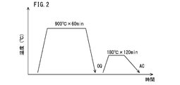
- FIG. 2 is a diagram showing heat patterns of quenching and tempering for test pieces for a hardenability evaluation test and a toughness evaluation test in Examples.
- FIG. 1 shows a bearing part (comparative example) obtained by quenching and tempering a steel material corresponding to SUJ2 defined in JIS G 4805 (2008), and the above chemical composition, and the formula (1) Carburizing the steel material of the present embodiment
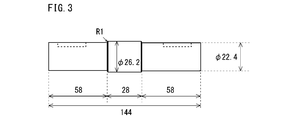
- FIG. 3 is a side view of an intermediate product of a small roller test piece used in the roller pitching test of the example.
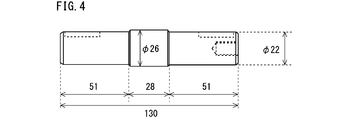
- FIG. 4 is a side view of a small roller test piece used in the roller pitching test of the example.
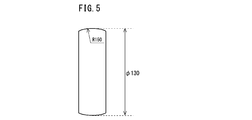
- FIG. 5 is a front view of a large roller used in the roller pitching test of the example.
- the present inventors have found that the machinability of a steel material as a raw material of a carbonitrided bearing part, and the wear resistance, the toughness of a core part, and the structure under a hydrogen generating environment in the carbonitrided bearing part after carbonitriding treatment.
- the peeling life due to the change was investigated and examined.
- the present inventors examined the chemical composition of the steel material to obtain the above-mentioned characteristics.
- C 0.15 to 0.45%
- Si 0.50% or less
- Mn 0.20 to 0.60%
- P 0.015% or less
- S 0.005 % Or less
- Cr 0.80 to 1.50%
- Mo 0.17 to 0.30%
- V 0.24 to 0.40%
- Al 0.005 to 0.100%
- N 0 0.0300% or less
- Ti 0 to 0.100%
- Ca 0 to 0.0010%
- a steel material having a chemical composition with the balance being Fe and impurities is used, machinability and carbonitrided bearing parts after carbonitriding treatment are used. It is considered that the abrasion resistance, the toughness of the core, and the peel
- V-carbide having a circle equivalent diameter of 150 nm or less In order to increase the peeling life of carbonitrided bearing parts in a hydrogen generation environment, in the carbonitrided bearing parts, V-carbide having a circle equivalent diameter of 150 nm or less, V-carbonitride having a circle equivalent diameter of 150 nm or less, and circle equivalent It is effective to generate a large number of one or more kinds selected from the group consisting of V-composite carbides having a diameter of 150 nm or less and V-composite carbonitrides having a circle equivalent diameter of 150 nm or less.
- the V composite carbide means a carbide containing V and Mo.
- the V composite carbonitride means a carbonitride containing V and Mo.
- V carbides and V carbonitrides are also referred to as “V carbides and the like”, and V composite carbides and V composite carbonitrides are referred to as “V composite carbides and the like”.
- V carbides and V composite carbides and the like V carbides and the like
- V carbides and V composite carbides and the like V carbides and the like
- a V carbide having a circle equivalent diameter of 150 nm or less is referred to as "small V carbide”
- a V composite carbide having a circle equivalent diameter of 150 nm or less is referred to as "small V composite carbide”.
- the equivalent circle diameter means the diameter of a circle having the same area as the area of V carbide or the like or V composite carbide or the like.
- the V carbide and the V composite carbide are small V carbides and the like having a circle equivalent diameter of 150 nm or less and the small V composite carbides, the small V carbides and the small V composite carbides trap hydrogen. Further, the small V carbide and the like and the small V composite carbide and the like are small in size, so that they are unlikely to be a starting point of cracking. Therefore, if the small V carbides and small V composite carbides are sufficiently dispersed in the carbonitrided bearing parts, it is difficult for the microstructure to change under the hydrogen generating environment, and as a result, the carbonitrided bearing parts under the hydrogen generating environment. The peeling life of can be increased.
- F1 is an index relating to the amount of small V carbides and the like, and small V composite carbides and the like that trap hydrogen and increase the peeling life of the carbonitrided bearing component under a hydrogen generating environment.
- the production of small V carbides and small V composite carbides is promoted by containing Cr and Mo as well as V.
- Cr produces Fe-based carbides such as cementite or Cr carbides in a temperature range lower than the temperature range in which V carbides and the like and V composite carbides and the like are generated.
- Mo produces Mo carbide (Mo 2 C) in a temperature range lower than the temperature range in which V carbide and the like and V composite carbide and the like are produced.
- Fe-based carbides, Cr-based carbides, and Mo-carbides form a solid solution to form precipitation nucleation sites for V-carbides and V-composite carbides.
- the equivalent circle diameter is V-carbides having a diameter of more than 150 nm and V-composite carbides having an equivalent circle diameter of more than 150 nm are produced.
- V-carbides having a circle equivalent diameter of more than 150 nm are also referred to as "coarse V carbides” and V-composite carbides having a circle-equivalent diameter of more than 150 nm are also referred to as "coarse V-composite carbides”.
- Coarse V carbides and coarse V composite carbides and the like have low ability to trap hydrogen, and are therefore likely to cause structural changes. Therefore, the coarse V carbide and the coarse V composite carbide reduce the peeling life of the carbonitrided bearing component under the hydrogen generation environment.
- F2 2.7C+0.4Si+Mn+0.45Ni+0.8Cr+Mo+V.
- Each element (C, Si, Mn, Ni, Cr, Mo and V) in F2 is a main element that enhances the hardenability of steel among the elements in the above chemical composition. Therefore, F2 is an index of the strength of the core of the carbonitrided bearing part and the machinability of the steel material.
- F2 is 2.20 or less, even if the content of each element in the chemical composition is within the range of the present embodiment and the formulas (1), (3) and (4) are satisfied, the steel material The hardenability of is not sufficient. Therefore, the strength of the core of the carbonitrided bearing component is not sufficient, and the peeling life of the carbonitrided bearing component in a hydrogen generating environment cannot be sufficiently obtained.
- F2 is 2.80 or more, even if the content of each element in the chemical composition is within the range of the present embodiment and the formulas (1), (3) and (4) are satisfied, However, the hardenability of steel becomes excessively high. In this case, sufficient machinability of the steel material cannot be obtained.
- F2 is higher than 2.20 and lower than 2.80, the content of each element in the chemical composition is within the range of the present embodiment, and the formula (1), the formula (3), and the formula (4) ) Is satisfied, sufficient machinability is obtained in the steel material. Further, the strength of the core portion of the carbonitrided bearing component is sufficiently increased, and the peeling life of the carbonitrided bearing component is sufficiently increased under the hydrogen generating environment.
- F3 Mo/V.
- F3 is less than 0.58, even if the content of each element in the chemical composition is within the range of the present embodiment and the formulas (1), (2) and (4) are satisfied, the size is small. V carbides and small V composite carbides are not sufficiently formed. As a result, the peeling life of the carbonitrided bearing component cannot be sufficiently obtained in the hydrogen generating environment. If F3 is 0.58 or more and the formula (3) is satisfied, the content of each element in the chemical composition is within the range of this embodiment, and the formula (1), the formula (2), and the formula (4) ) Is satisfied, small V carbides and the like and small V composite carbides and the like are sufficiently generated. As a result, the peeling life of the carbonitrided bearing component becomes sufficiently long under the hydrogen generation environment.
- F4 (Mo+V+Cr)/(Mn+20P).
- F4 is 2.40 or more, it is assumed that the content of each element in the chemical composition is within the range of the present embodiment and that the formulas (1) to (3) are satisfied, and the strengthening in the crystal grains is performed. A synergistic effect of the mechanism, the grain boundary strengthening mechanism, and the hydrogen invasion suppressing mechanism can be obtained, and the peeling life of the carbonitrided bearing component under a hydrogen generating environment can be sufficiently obtained.
- the ratio of the V content (mass %) in the electrolytic extraction residue of the steel material to the V content (mass %) in the chemical composition of the steel material is 10.0% or less.
- V carbides and V composite carbides should be as solid as possible in the steel material used for the carbonitrided bearing parts. It is preferable that it is melted. If V carbides, V composite carbides, etc. remain in the steel material, the V carbides, V composite carbides, etc. remaining in the steel material grow and coarsen during the carbonitriding bearing component manufacturing process. Coarse V carbides and coarse V composite carbides have a low ability to trap hydrogen during the use of carbonitrided bearing parts under a hydrogen generating environment.
- coarse V carbide and the like and coarse V composite carbide and the like are likely to cause a structural change during use of the carbonitrided bearing component in a hydrogen generating environment, and are also likely to be a starting point of cracking. Therefore, the peeling life of the carbonitrided bearing component is reduced.
- residue V amount ratio RA V defined in (A) is not more than 10.0%.
- RA V [V] R / [V] C ⁇ 100 (A) If the V content ratio RA V in the residue is 10.0% or less, V carbide and the like and V composite carbide and the like are sufficiently solid-dissolved in the steel material that is the material of the carbonitrided bearing component. Therefore, the reduction of the peeling life of the carbonitrided bearing component under the hydrogen generation environment due to the coarse V carbide and the like and the coarse V composite carbide and the like is suppressed.
- FIG. 1 shows a bearing component (comparative example) obtained by quenching and tempering a steel material corresponding to SUJ2 defined in JIS G 4805 (2008), and the above chemical composition, In a bearing component (carbonitrided bearing component: example of the present invention) manufactured by carbonitriding the steel material of the present embodiment satisfying (4) and having a V content ratio RA V in the residue of 10.0% or less.
- FIG. 3 is a diagram showing a stripping life under a hydrogen generation environment. The peeling life test under a hydrogen generating environment was carried out by the method described in Examples below.
- the vertical axis of FIG. 1 represents the ratio of the peeling life of each inventive example to the peeling life of the comparative example (hereinafter referred to as the peeling life ratio) when the peeling life of the comparative example is defined as 1.0 (reference). Show.
- the exfoliation life of a bearing component of a conventional chemical composition (comparative example) under a hydrogen generating environment is at least 2.0 times as long as the exfoliation life of the inventive example under a hydrogen generating environment. Is over.
- the peeling life of the carbonitrided bearing component manufactured using the steel material of the present embodiment under the hydrogen generating environment is extremely remarkably improved as compared with the conventional bearing component.
- the steel material that is the material of the carbonitrided bearing component according to the present embodiment completed based on the above knowledge has the following configuration.
- the chemical composition is In mass %, C: 0.15 to 0.45%, Si: 0.50% or less, Mn: 0.20-0.60%, P: 0.015% or less, S: 0.005% or less, Cr: 0.80 to 1.50%, Mo: 0.17 to 0.30%, V: 0.24 to 0.40%, Al: 0.005 to 0.100%, N: 0.0300% or less, O: 0.0015% or less, Cu: 0 to 0.20%, Ni: 0 to 0.20%, B: 0 to 0.0050%, Nb: 0-0.100%, Ti: 0 to 0.100%, Ca: 0 to 0.0010%, and
- the balance consists of Fe and impurities, Satisfying the formulas (1) to (4),
- the total area ratio of ferrite and pearlite in the microstructure is 10.0% or more, and the balance consists of bainite,
- the ratio of the V content (mass %) in the electrolytic extraction residue to the V content (mass %) in the chemical composition is 10.
- the steel material according to [1] The chemical composition is Cu: 0.01 to 0.20%, Ni: 0.01 to 0.20%, B: 0.0001 to 0.0050%, Nb: 0.005 to 0.100%, and Ti: 0.005 to 0.100%, containing one element or two or more elements selected from the group consisting of: Steel material.
- the steel material according to [1] or [2], The chemical composition is Ca: contains 0.0001 to 0.0010%, Steel material.
- the steel material of this embodiment is a raw material for carbonitrided bearing parts.
- the chemical composition of the steel material of this embodiment contains the following elements.
- C 0.15 to 0.45% Carbon (C) enhances the hardenability of steel. Therefore, the strength of the core portion and the toughness of the core portion of the carbonitrided bearing component manufactured using the steel material of the present embodiment as the raw material are increased. C further forms fine carbides and carbonitrides by carbonitriding to enhance the wear resistance of carbonitrided bearing components. Furthermore, C mainly forms small V carbides and small V composite carbides during carbonitriding. Small V carbides and small V composite carbides trap hydrogen in steel during the use of carbonitrided bearing parts in a hydrogen generating environment. Therefore, the small V carbide and the small V composite carbide increase the peeling life of the carbonitrided bearing component under the hydrogen generation environment.
- the C content is less than 0.15%, the above effects cannot be sufficiently obtained even if the content of other elements in the chemical composition is within the range of this embodiment.
- the C content exceeds 0.45%, even if the content of other elements is within the range of the present embodiment, V carbides, V composite carbides, etc. are not completely dissolved in the steel material manufacturing process. Remains in. The remaining V carbides and V composite carbides do not form a solid solution sufficiently in the manufacturing process of carbonitrided bearing parts. Then, the V carbides and V composite carbides and the like remaining in the steel material grow during the manufacturing process of the carbonitrided bearing component and remain as coarse V carbides and V composite carbides and the like in the carbonitrided bearing component.
- the C content is 0.15 to 0.45%.
- the preferable lower limit of the C content is 0.16%, more preferably 0.17%, and further preferably 0.18%.
- the preferable upper limit of the C content is 0.40%, more preferably 0.35%, and further preferably 0.32%.
- Si Silicon
- Si is inevitably contained. That is, the Si content is more than 0%. Si enhances the hardenability of the steel material, and further forms a solid solution with the ferrite of the steel material to strengthen the ferrite. This increases the strength of the core of the carbonitrided bearing component.
- the Si content is 0.50% or less.
- the preferable lower limit of the Si content is 0.01%, more preferably 0.02%, and further preferably 0.05%.
- the preferable upper limit of the Si content is 0.40%, more preferably 0.35%, further preferably 0.32%, and further preferably 0.30%.
- Mn 0.20-0.60%
- Manganese (Mn) enhances the hardenability of steel materials. As a result, the strength of the core of the carbonitrided bearing component is increased, and the peeling life of the carbonitrided bearing component in a hydrogen generating environment is increased. If the Mn content is less than 0.20%, the above effects cannot be sufficiently obtained even if the content of other elements is within the range of this embodiment. On the other hand, if the Mn content exceeds 0.60%, the hardness of the steel material becomes too high and the machinability of the steel material deteriorates, even if the content of other elements is within the range of this embodiment.
- the Mn content is 0.20 to 0.60%.
- the preferable lower limit of the Mn content is 0.22%, more preferably 0.24%, and further preferably 0.26%.
- the preferable upper limit of the Mn content is 0.55%, more preferably 0.50%, and further preferably 0.45%.
- Phosphorus (P) is an unavoidable impurity. That is, the P content is more than 0%. P segregates at the grain boundaries and reduces the grain boundary strength. If the P content exceeds 0.015%, even if the content of other elements is within the range of the present embodiment, P is excessively segregated at the grain boundaries to lower the grain boundary strength. As a result, the peeling life of the carbonitrided bearing component in a hydrogen generating environment is reduced. Therefore, the P content is 0.015% or less.
- the upper limit of the P content is preferably 0.013%, more preferably 0.010%. It is preferable that the P content is as low as possible. However, excessive reduction of P content raises manufacturing cost. Therefore, in consideration of normal industrial production, the lower limit of the P content is preferably 0.001%, and more preferably 0.002%.
- S 0.005% or less Sulfur (S) is an unavoidable impurity. That is, the S content is more than 0%. S produces sulfide-based inclusions. Coarse sulfide-based inclusions are likely to be the starting point of cracking during the use of carbonitrided bearing parts in a hydrogen generating environment. If the S content exceeds 0.005%, even if the content of other elements is within the range of the present embodiment, the sulfide-based inclusions become coarse, and the carbonitrided bearing component peels off in a hydrogen generating environment. The life is shortened. Therefore, the S content is 0.005% or less.
- the preferable upper limit of the S content is 0.004%, and more preferably 0.003%. It is preferable that the S content is as low as possible. However, excessive reduction of S content raises manufacturing cost. Therefore, in consideration of ordinary industrial production, the lower limit of the S content is preferably 0.001%, more preferably 0.002%.
- Chromium (Cr) enhances the hardenability of steel materials. This increases the strength of the core of the carbonitrided bearing component. Cr is further contained in combination with V and Mo to promote generation of small V carbides and small V composite carbides during carbonitriding. As a result, not only the wear resistance of the carbonitrided bearing component but also the peeling life of the carbonitrided component in a hydrogen generating environment is increased. If the Cr content is less than 0.80%, the above effect cannot be sufficiently obtained. On the other hand, if the Cr content exceeds 1.50%, the carburizing property at the time of carbonitriding treatment deteriorates even if the content of other elements is within the range of this embodiment.
- the Cr content is 0.80 to 1.50%.
- the preferable lower limit of the Cr content is 0.85%, more preferably 0.88%, and further preferably 0.90%.
- the preferable upper limit of the Cr content is 1.45%, more preferably 1.40%, and further preferably 1.35%.
- Mo 0.17 to 0.30% Molybdenum (Mo), like Cr, enhances the hardenability of steel materials. This increases the strength of the core of the carbonitrided bearing component. Mo is further contained in combination with V and Cr to promote generation of small V carbides and small V composite carbides during carbonitriding. As a result, not only the wear resistance of the carbonitrided bearing component but also the peeling life of the carbonitrided bearing component in a hydrogen generating environment is increased. If the Mo content is less than 0.17%, the above effect cannot be sufficiently obtained. On the other hand, if the Mo content exceeds 0.30%, the strength of the steel material becomes too high. In this case, the machinability of the steel material decreases.
- the Mo content is 0.17 to 0.30%.
- the preferable lower limit of the Mo content is 0.18%, more preferably 0.19%, and further preferably 0.20%.
- the preferable upper limit of the Mo content is 0.29%, more preferably 0.28%, and further preferably 0.27%.
- V 0.24 to 0.40% Vanadium (V) forms small V carbides and small V composite carbides and the like in the process of manufacturing carbonitrided bearing parts using steel.
- the small V carbides and the small V composite carbides trap hydrogen that has entered the carbonitrided bearing components during use of the carbonitrided bearing components in a hydrogen generating environment.
- the equivalent circle diameter of small V carbides and small V composite carbides in carbonitrided bearing parts is as small as 150 nm or less. Therefore, even if small V carbides and small V composite carbides trap hydrogen, they are unlikely to be the starting points of structural changes. Therefore, the peeling life of the carbonitrided bearing component in a hydrogen generating environment is increased.
- V further forms small V carbides and small V composite carbides in the manufacturing process of carbonitrided bearing parts to enhance the wear resistance of carbonitrided bearing parts. If the V content is less than 0.24%, the above effect cannot be sufficiently obtained. On the other hand, if the V content exceeds 0.40%, even if the content of other elements is within the range of the present embodiment, V carbides and V composite carbides are not completely dissolved in the steel material manufacturing process. To remain. The remaining V carbides and V composite carbides, etc. do not dissolve sufficiently in the manufacturing process of carbonitrided bearing parts, and grow during the manufacturing process of carbonitrided bearing parts to form coarse V carbides and coarse V composite carbides.
- V carbides and coarse V composite carbides reduce the toughness of the core of carbonitrided bearing parts. Further, the coarse V carbide and the like and the coarse V composite carbide and the like in the carbonitrided bearing component have a low ability to trap hydrogen. Therefore, the coarse V-carbide and the coarse V-composite carbide are likely to cause a structural change during the use of the carbonitrided bearing component under the hydrogen generation environment. Coarse V carbides and coarse V composite carbides also serve as crack initiation points. Therefore, the coarse V carbide and the coarse V composite carbide reduce the peeling life of the carbonitrided bearing part under the hydrogen generation environment. Therefore, the V content is 0.24 to 0.40%. The preferable lower limit of the V content is 0.25%, more preferably 0.26%, and further preferably 0.27%. The preferable upper limit of the V content is 0.39%, more preferably 0.38%, and further preferably 0.36%.
- Al 0.005 to 0.100%
- Aluminum (Al) deoxidizes steel. If the Al content is less than 0.005%, the above effect cannot be sufficiently obtained even if the content of other elements is within the range of this embodiment. On the other hand, if the Al content exceeds 0.100%, coarse oxide-based inclusions are generated even if the content of other elements is within the range of this embodiment. Coarse oxide-based inclusions are the starting point for fatigue failure of carbonitrided bearing parts under hydrogen generation environment. Therefore, the peeling life of the carbonitrided bearing component in a hydrogen generating environment is shortened. Therefore, the Al content is 0.005 to 0.100%.
- the preferable lower limit of the Al content is 0.008%, more preferably 0.010%.
- the preferable upper limit of the Al content is 0.080%, more preferably 0.070%, further preferably 0.060%.
- the Al content as used herein means the content of total Al (Total Al).
- N 0.0300% or less Nitrogen (N) is an unavoidable impurity. That is, the N content is more than 0%. N forms a solid solution in the steel material and reduces the hot workability of the steel material. If the N content exceeds 0.0300%, the hot workability of the steel material is significantly reduced. Therefore, the N content is 0.0300% or less.
- the preferable upper limit of the N content is 0.0250%, more preferably 0.0200%, further preferably 0.0150%, further preferably 0.0130%.
- the N content is preferably as low as possible. However, excessive reduction of N content raises manufacturing costs. Therefore, in consideration of ordinary industrial production, the lower limit of the N content is preferably 0.0001%, and more preferably 0.0002%.
- Oxygen (O) is an impurity that is inevitably contained. That is, the O content is more than 0%. O combines with other elements in the steel to form coarse oxide-based inclusions. Coarse oxide-based inclusions are the starting point for fatigue failure of carbonitrided bearing parts under hydrogen generation environment. Therefore, the peeling life of the carbonitrided bearing component in a hydrogen generating environment is shortened. When the O content exceeds 0.0015%, the peeling life of the carbonitrided bearing component in a hydrogen generating environment is significantly reduced even if the content of other elements is within the range of this embodiment. Therefore, the O content is 0.0015% or less.
- the preferable upper limit of the O content is 0.0013%, and more preferably 0.0012%.
- the O content is preferably as low as possible. However, excessive reduction of O content raises manufacturing cost. Therefore, in consideration of ordinary industrial production, the lower limit of the O content is preferably 0.0001%, and more preferably 0.0002%.
- the balance of the chemical composition of the steel material according to this embodiment is Fe and impurities.
- the impurities are those that are mixed from the ore as a raw material, scrap, or the manufacturing environment when the steel material is industrially manufactured, and are allowed within a range that does not adversely affect the steel material of the present embodiment. Means what is done.
- the chemical composition of the steel material of the present embodiment may further contain one kind or two or more kinds selected from the group consisting of Cu, Ni, B, Nb and Ti, instead of part of Fe. These elements are optional elements, and all increase the strength of the carbonitrided bearing component.
- Cu 0 to 0.20%
- Copper (Cu) is an optional element and may not be contained. That is, the Cu content may be 0%.
- Cu enhances the hardenability of the steel material. This increases the strength of the steel material and the strength of the core of the carbonitrided bearing component. If Cu is contained even a little, the above effect can be obtained to some extent. However, if the Cu content exceeds 0.20%, the strength of the steel material excessively increases and the machinability of the steel material deteriorates even if the content of other elements is within the range of this embodiment. Therefore, the Cu content is 0 to 0.20%.
- the preferable lower limit of the Cu content is more than 0%, more preferably 0.01%, further preferably 0.02%, further preferably 0.03%, further preferably 0.05%. Is.
- the preferable upper limit of the Cu content is 0.18%, more preferably 0.16%, and further preferably 0.15%.
- Nickel (Ni) is an optional element and may not be contained. That is, the Ni content may be 0%. When contained, Ni enhances the hardenability of the steel material. This increases the strength of the steel material and the strength of the core of the carbonitrided bearing component. If Ni is contained even a little, the above effect can be obtained to some extent. However, if the Ni content exceeds 0.20%, the strength of the steel material excessively increases and the machinability of the steel material deteriorates even if the content of other elements is within the range of this embodiment. Therefore, the Ni content is 0 to 0.20%.
- the preferable lower limit of the Ni content is more than 0%, more preferably 0.01%, further preferably 0.02%, further preferably 0.03%, further preferably 0.05%. Is.
- the preferable upper limit of the Ni content is 0.18%, more preferably 0.16%, and further preferably 0.15%.
- B 0 to 0.0050%
- Boron (B) is an optional element and may not be contained. That is, the B content may be 0%. When contained, B enhances the hardenability of the steel material. This increases the strength of the steel material and the strength of the core of the carbonitrided bearing component. B further suppresses P from segregating at the grain boundaries. If B is contained in even a small amount, the above effect can be obtained to some extent. However, if the B content exceeds 0.0050%, B nitride (BN) is generated and the toughness of the core portion of the carbonitrided bearing component is reduced. Therefore, the B content is 0 to 0.0050%.
- the preferable lower limit of the B content is more than 0%, more preferably 0.0001%, further preferably 0.0003%, further preferably 0.0005%, further preferably 0.0010%. Is.
- the preferable upper limit of the B content is 0.0030%, more preferably 0.0025%, and further preferably 0.0020%.
- Niobium (Nb) is an optional element and may not be contained. That is, the Nb content may be 0%. When contained, Nb combines with C and N in steel to form carbides, nitrides, and carbonitrides. These precipitates enhance the strength of carbonitrided bearing parts by precipitation strengthening. If Nb is contained even a little, the above effect can be obtained to some extent. However, if the Nb content exceeds 0.100%, the toughness of the core portion of the carbonitrided bearing component decreases. Therefore, the Nb content is 0 to 0.100%.
- the preferable lower limit of the Nb content is more than 0%, more preferably 0.005%, further preferably 0.010%.
- the preferable upper limit of the Nb content is 0.080%, more preferably 0.070%, further preferably 0.050%, further preferably 0.040%.
- Titanium (Ti) is an optional element and may not be contained. That is, the Ti content may be 0%. When included, Ti forms carbides, nitrides, and carbonitrides similar to Nb, increasing the strength of carbonitrided bearing components. If Ti is contained even a little, the above effect can be obtained to some extent. However, if the Ti content exceeds 0.100%, the toughness of the core portion of the carbonitrided bearing component decreases. Therefore, the Ti content is 0 to 0.100%.
- the preferable lower limit of the Ti content is more than 0%, more preferably 0.005%, further preferably 0.010%.
- the preferable upper limit of the Ti content is 0.080%, more preferably 0.070%, further preferably 0.050%, further preferably 0.040%.
- the chemical composition of the steel material of the present embodiment may further contain Ca instead of part of Fe.
- Ca 0 to 0.0010%
- Calcium (Ca) is an optional element and may not be contained. That is, the Ca content may be 0%. When contained, Ca forms a solid solution with the inclusions in the steel material to make the sulfide fine and spherical. In this case, the hot workability of the steel material is enhanced. If Ca is contained even in a small amount, the above effect can be obtained to some extent. However, if the Ca content exceeds 0.0010%, coarse oxide inclusions are formed in the steel material. If the coarse oxide-based inclusions trap hydrogen during the use of the carburized bearing component in a hydrogen generating environment, a microstructure change is likely to occur. The occurrence of structural change shortens the peeling life of carbonitrided bearing parts.
- the Ca content is 0 to 0.0010%.
- the preferable lower limit of the Ca content is more than 0%, more preferably 0.0001%, and further preferably 0.0003%.
- the preferable upper limit of the Ca content is 0.0009%, more preferably 0.0008%.
- the chemical composition of the steel material of the present embodiment further satisfies the following formulas (1) to (4). 1.50 ⁇ 0.4Cr+0.4Mo+4.5V ⁇ 2.45 (1) 2.20 ⁇ 2.7C+0.4Si+Mn+0.45Ni+0.8Cr+Mo+V ⁇ 2.80 (2) Mo/V ⁇ 0.58 (3) (Mo+V+Cr)/(Mn+20P) ⁇ 2.40 (4) Here, the content (mass %) of the corresponding element is substituted for each element symbol in the formulas (1) to (4).
- F1 is a small V carbide or the like (small V carbide or small V carbonitride) or a small V composite carbide (small V composite carbide or the like) that traps hydrogen and enhances the peeling life of the carbonitrided bearing component under a hydrogen generating environment. It is an index for the generation of small V composite carbonitrides. As described above, the generation of small V carbides and small V composite carbides is promoted by the inclusion of Cr and Mo as well as V. Cr produces Fe-based carbides such as cementite or Cr carbides in a temperature range lower than the temperature range in which V carbides and the like and V composite carbides and the like are generated.
- Mo produces Mo carbide (Mo 2 C) in a temperature range lower than the temperature range in which V carbide and the like and V composite carbide and the like are produced. As the temperature rises, Fe-based carbides, Cr-based carbides, and Mo-carbides form a solid solution to form precipitation nucleation sites for V-carbides and V-composite carbides.
- the V carbide and the like and the V composite carbide and the like remain in the steel material without sufficiently forming a solid solution. Therefore, in the manufacturing process of the carbonitrided bearing component, the V carbides and V composite carbides and the like remaining in the steel material grow to become coarse V carbides and coarse V composite carbides. Coarse V carbides and coarse V composite carbides have low hydrogen trapping ability. Therefore, the coarse V-carbide and the coarse V-composite carbide are likely to cause a structural change during the use of the carbonitrided bearing component under the hydrogen generation environment. Coarse V carbides and coarse V composite carbides also serve as crack initiation points. Therefore, the peeling life of the carbonitrided bearing component in a hydrogen generating environment is shortened.
- the preferable lower limit of F1 is 1.51, more preferably 1.52, further preferably 1.54, further preferably 1.55, and further preferably 1.56.
- the preferable upper limit of F1 is 2.44, more preferably 2.43, and further preferably 2.42.
- the value of F1 shall be the value obtained by rounding off the third decimal place.
- F2 is an index of the strength of the core of the carbonitrided bearing component.
- F2 is 2.20 or less, even if the content of each element in the chemical composition is within the range of the present embodiment and the formulas (1), (3) and (4) are satisfied, the steel material The hardenability of is not sufficient. Therefore, the strength of the core of the carbonitrided bearing component is not sufficient. In this case, the peeling life of the carbonitrided bearing component cannot be sufficiently obtained in the hydrogen generating environment.
- F2 is 2.80 or more, even if the content of each element in the chemical composition is within the range of the present embodiment and the formulas (1), (3) and (4) are satisfied, However, the hardenability of steel becomes excessively high. In this case, in the microstructure of the steel material, the total area ratio of ferrite and pearlite is less than 10.0%. Therefore, the machinability of the steel material cannot be sufficiently obtained.
- F2 is higher than 2.20 and lower than 2.80, the content of each element in the chemical composition is within the range of the present embodiment, and the formula (1), the formula (3), and the formula (4) ) Is satisfied, sufficient machinability is obtained in the steel material. Further, the strength of the core portion of the carbonitrided bearing component is sufficiently increased, and the peeling life of the carbonitrided bearing component is sufficiently increased under the hydrogen generating environment.
- the preferable lower limit of F2 is 2.23, more preferably 2.25, further preferably 2.30, further preferably 2.35, and further preferably 2.45.
- the preferable upper limit of F2 is 2.78, more preferably 2.75, further preferably 2.73, and further preferably 2.70.
- the value of F2 shall be the value obtained by rounding off the third decimal place.
- F3 Mo/V.
- the total V content, Cr content, and Mo content necessary for producing small V carbides and small V composite carbides are summed up. The content is obtained.
- F3 is 0.58 or more and the formula (3) is satisfied, the content of each element in the chemical composition is within the range of this embodiment, and the formula (1), the formula (2), and the formula (4) ) Is satisfied, small V carbides and small V composite carbides are sufficiently generated in the carbonitrided bearing component. As a result, the peeling life of the carbonitrided bearing component under hydrogen generating environment is sufficiently long.
- the preferable lower limit of F3 is 0.60, more preferably 0.65, further preferably 0.68, further preferably 0.70, further preferably 0.73, and further preferably It is 0.76.
- the value of F3 shall be the value obtained by rounding off the third decimal place.
- F4 (Mo+V+Cr)/(Mn+20P).
- Small V carbides and small V composite carbides not only trap hydrogen but also strengthen the inside of crystal grains by precipitation strengthening.
- (a) intra-grain strengthening (b) crystal grain boundary strengthening, (c) Due to the three synergistic effects of suppressing hydrogen invasion, the peeling life of carbonitrided bearing parts in a hydrogen generating environment is further extended.
- the intra-grain strengthening of (a) depends on the total content of Mo content, V content, and Cr content as described above.
- F4 is 2.40 or more, it is assumed that the content of each element in the chemical composition is within the range of the present embodiment and that the formulas (1) to (3) are satisfied, and the strengthening in the crystal grains is performed. A synergistic effect of the mechanism, the grain boundary strengthening mechanism, and the hydrogen invasion suppressing mechanism can be obtained, and the peeling life of the carbonitrided bearing component under a hydrogen generating environment can be sufficiently obtained.
- the preferable lower limit of F4 is 2.42, more preferably 2.45, further preferably 2.47, further preferably 2.50, and further preferably 2.52.
- the value of F4 shall be the value obtained by rounding off the third decimal place.
- the microstructure of the steel material of the present embodiment means a structure in which the total area ratio of ferrite and pearlite is 10.0% or more and the balance is bainite.
- the C content in the chemical composition is low, in the microstructure of the steel material of the present embodiment, the total area ratio of ferrite and pearlite is 50.0% or more, and the balance is bainite.
- the C content in the chemical composition is high, in the microstructure of the steel material of the present embodiment, the area ratio of bainite is 50.0% or more, and the balance consists of ferrite and pearlite.
- the total area ratio of ferrite and pearlite is at least 10.0% or more, and the balance consists of bainite.
- the preferable total area ratio of ferrite and pearlite is 10.0 to 90.0%, and the balance is bainite.
- the preferable upper limit of the total area ratio of ferrite and pearlite is 80.0%, and more preferably 78.0%.
- the preferred lower limit of ferrite and pearlite is 20.0%, more preferably 25.0%.
- regions other than bainite, ferrite and pearlite are, for example, retained austenite, precipitates (including cementite) and inclusions, but the total austenite, precipitates and inclusions in the microstructure are The area ratio is so small that it can be ignored.
- the total area ratio (%) of ferrite and pearlite and the area ratio (%) of bainite in the microstructure of the steel material of this embodiment are measured by the following method.
- a sample is taken from the center position (R/2 position) of the radius R connecting the surface and the central axis in the cross section (hereinafter referred to as the cross section) perpendicular to the longitudinal direction (axial direction) of the steel bar or the steel material which is the wire rod. ..
- the surface corresponding to the above-mentioned cross section is the observation surface.
- the observation surface is etched using 2% nitric acid alcohol (nital etchant). The etched observation surface is observed using a 500 ⁇ optical microscope, and a photographic image of arbitrary 20 fields of view is generated. The size of each visual field is 100 ⁇ m ⁇ 100 ⁇ m.
- each phase is specified based on the contrast.
- the total area ([mu] m 2) of the ferrite in each field and determines the total area of perlite ( ⁇ m 2).
- the ratio of the total area of the total area of ferrite and the total area of pearlite in all the visual fields to the total area of all the visual fields is defined as the total area ratio (%) of ferrite and pearlite.
- the total area ratio (%) of ferrite and pearlite is a value obtained by rounding the second decimal place.
- V carbide and the like and V composite carbide and the like are sufficiently dissolved, and the residual amount of V carbide and the like and V composite carbide and the like is sufficiently low.
- the residue V amount ratio RA V defined by formula (A) is not more than 10.0%.
- residue V amount ratio RA V exceeds 10.0%, the steel, V carbides and V composite carbides are not sufficiently dissolved.
- the V carbides and V composite carbides remaining in the steel material grow to become coarse V carbides and coarse V composite carbides. ..
- Coarse V carbides and coarse V composite carbides have low hydrogen trapping ability. Therefore, the coarse V carbide and the coarse V composite carbide and the like are likely to cause a structural change during the use of the carbonitrided bearing component in a hydrogen generating environment. If the microstructure is changed, the peeling life of the carbonitrided bearing part in a hydrogen generating environment is shortened.
- the preferable upper limit of the residue V amount ratio RA V is 9.5%, more preferably 9.2%, more preferably 9.0%, more preferably 8.5%, more preferably Is 8.3%, more preferably 8.0%, further preferably 7.5%, further preferably 7.0%, further preferably 6.5%, and further preferably Is 6.0%.
- the V content in the electrolytic extraction residue of the steel material of this embodiment can be measured by the following method. First, the precipitates and inclusions in the steel material are captured as a residue. A cylindrical test piece having a diameter of 6 mm and a length of 50 mm is taken from the steel material. Specifically, three cylindrical test pieces are sampled from the R/2 position of a cross section (hereinafter referred to as a cross section) perpendicular to the longitudinal direction (axial direction) of the steel material. The surface of the sampled cylindrical test piece is polished by preliminary electrolytic polishing to about 50 ⁇ m to obtain a new surface.
- a cross section perpendicular to the longitudinal direction (axial direction) of the steel material.
- the electrolytically polished cylindrical test piece is electrolyzed with an electrolytic solution (10% acetylacetone+1% tetraammonium+methanol).
- the electrolytic solution after electrolysis is filtered through a 0.2 ⁇ m filter to capture the residue.
- the obtained electrolysis extraction residue is acid-decomposed and ICP (inductively coupled plasma) emission analysis is performed to quantify the V content in the electrolysis extraction residue when the steel material (base material) is 100 mass %.
- the arithmetic mean value of V content in the electrolytic extraction residue of each columnar test piece (that is, the arithmetic mean value of three V contents) is defined as V content [V] R in the electrolytic extraction residue of steel.
- V content [V] R in the electrolytic extraction residue is a value obtained by rounding off the second decimal place of the arithmetic mean value.
- Residue V amount ratio RA V is a value obtained by rounding off to one decimal place.
- RA V [V] R / [V] C ⁇ 100 (A)
- the content of each element is within the range of the present embodiment described above, and F1 to F4 satisfy the formulas (1) to (4).
- the microstructure comprising a ferrite and a total area ratio of pearlite of 10.0% or more balance being bainite, further residue V amount ratio RA V is less than or equal to 10.0%. Therefore, the steel material of this embodiment is excellent in machinability. Furthermore, after performing hot forging treatment on the steel material of the present embodiment, in a carbonitrided bearing component obtained by carbonitriding treatment, excellent wear resistance and excellent toughness of the core portion are obtained, and further, Excellent peeling life is obtained for carbonitrided bearing parts under hydrogen generation environment.
- the method for manufacturing a steel material described below is an example for manufacturing a steel material that is a raw material for the carbonitrided bearing component of the present embodiment. Therefore, the steel material having the above configuration may be manufactured by a manufacturing method other than the manufacturing method described below. However, the manufacturing method described below is a preferred example of the method for manufacturing the steel material of the present embodiment.
- An example of the method for manufacturing a steel material according to the present embodiment includes a steelmaking step of refining molten steel and casting the material (cast slab), and a hot working step of hot working the material to produce a steel material. ..
- a steelmaking step of refining molten steel and casting the material (cast slab) and a hot working step of hot working the material to produce a steel material. ..
- each step will be described.
- Step making process In the steelmaking process, first, molten steel having the above chemical composition in which the content of each element is within the range of the present embodiment and F1 to F4 satisfy the formulas (1) to (4) is manufactured.
- the refining method is not particularly limited, and a known method may be used.
- refining (primary refining) in a converter is performed on the hot metal produced by a known method.
- the well-known secondary refining is performed on the molten steel tapped from the converter.
- addition of alloying elements for component adjustment is performed, and the content of each element is within the range of this embodiment, and F1 to F4 are chemical compositions satisfying formulas (1) to (4).
- the raw material is manufactured by the well-known casting method using the molten steel manufactured by the above refining method.
- molten steel is used to produce an ingot by the ingot making method.
- bloom or billet may be manufactured by continuous casting method using molten steel.
- the material (bloom, ingot) is manufactured by the above method.
- the material (bloom or ingot) manufactured in the steel manufacturing step is subjected to hot working to manufacture a steel material.
- the steel material is a steel bar or a wire rod.
- the hot working process includes a rough rolling process and a finish rolling process.
- the material is hot worked to produce a billet.
- the rough rolling process uses, for example, a slab mill.
- the slab is rolled by a slab to produce a billet.
- a continuous rolling mill is installed downstream of the slab, the bilge-rolled billet is further hot-rolled using a continuous rolling mill to produce a smaller billet. May be.
- a horizontal stand having a pair of horizontal rolls and a vertical stand having a pair of vertical rolls are alternately arranged in a line.
- the heating temperature and holding time in the heating furnace in the rough rolling process are as follows. Heating temperature: 1150 to 1300°C Holding time at the heating temperature: 1.5 to 10.0 hours
- the heating temperature is the furnace temperature (° C.) of the heating furnace.
- the holding time is the holding time (hour) when the furnace temperature of the heating furnace is 1150 to 1300°C.
- the heating temperature is less than 1150° C. or the holding time at the heating temperature of 1150 to 1300° C. is less than 1.5 hours, the V carbides and V composite carbides in the raw material will not be sufficiently dissolved. Therefore, the residue V amount ratio RA V in the steel exceeds 10.0%.
- the heating temperature exceeds 1300° C. or the holding time at 1150 to 1300° C. exceeds 10.0 hours, the unit consumption becomes excessively high and the manufacturing cost becomes high.
- the heating temperature in the rough rolling step is 1150 to 1300°C and the holding time at 1150 to 1300°C is 1.5 to 10.0 hours, the V carbides and V composite carbides in the material are sufficient. Dissolve in.
- the billet is first heated using a heating furnace.
- the billet after heating is hot-rolled using a continuous rolling mill to manufacture a steel bar or a wire rod.
- the heating temperature and holding time in the heating furnace in the finish rolling process are as follows. Heating temperature: 1150 to 1300°C Holding time at the heating temperature: 1.5 to 5.0 hours
- the heating temperature is the furnace temperature (° C.) of the heating furnace.
- the holding time is the holding time (hour) when the furnace temperature of the heating furnace is 1150 to 1300°C.
- the heating temperature in the heating furnace in the finish rolling process is less than 1150°C or the holding time at 1150 to 1300°C is less than 1.5 hours, the load applied to the rolling mill during finish rolling becomes excessively large. .. On the other hand, if the heating temperature exceeds 1300° C. or the holding time at 1150 to 1300° C. exceeds 5.0 hours, the unit consumption becomes excessively high and the manufacturing cost becomes high.
- the heating temperature in the finish rolling step is 1150 to 1300° C. and the holding time at 1150 to 1300° C. is 1.5 to 5.0 hours, V carbides and V composite carbides in the material Dissolve sufficiently.
- the steel material after finish rolling is cooled at a cooling rate equal to or lower than cooling to manufacture the steel material of this embodiment.
- the average cooling rate CR in the temperature range where the steel material temperature is 800°C to 500°C is 0.1 to 5.0°C/sec.
- a phase transformation from austenite to ferrite, pearlite, or bainite occurs.
- the microstructure has a total area ratio of ferrite and pearlite of 10.0% or more. Yes, and the balance consists of bainite.
- the average cooling rate CR is measured by the following method.
- the steel material after finish rolling is conveyed downstream in the conveying line.
- a plurality of thermometers are arranged along the transfer line, and the steel material temperature at each position of the transfer line can be measured. Based on a plurality of thermometers arranged along the transfer line, the time until the temperature of the steel material reaches 800°C to 500°C is obtained, and the average cooling rate CR (°C/sec) is obtained.
- the average cooling rate CR can be adjusted by disposing a plurality of slow cooling covers at intervals on the transfer line.
- the steel material of this embodiment having the above-mentioned configuration can be manufactured by the above manufacturing process.
- the steel material of this embodiment is used for carbonitriding bearing parts.
- the carbonitrided bearing component means a bearing component that has been carbonitrided.
- the carbonitriding treatment means a treatment for performing carbonitriding quenching and tempering.
- Bearing parts mean parts of rolling bearings.
- the bearing component is, for example, a bearing ring, a bearing washer, a rolling element, or the like.
- the bearing ring may be an inner ring or an outer ring, and the bearing washer may be an axial bearing washer, a housing bearing washer, a central bearing washer, or a centering housing bearing washer.
- the bearing ring and the bearing washer are not particularly limited as long as they are members having a raceway surface.
- the rolling elements may be balls or rollers.
- the rollers are, for example, cylindrical rollers, rod rollers, needle rollers, tapered rollers, convex rollers and the like.
- the carbonitrided bearing part includes a carbonitrided layer formed on the surface layer by carbonitriding treatment, and a core portion inside the carbonitrided layer.
- the depth of the carbonitriding layer is not particularly limited, but the depth from the surface of the carbonitriding layer is, for example, 0.2 mm to 5.0 mm.
- the chemical composition of the core portion is the same as the chemical composition of the steel material of this embodiment.
- An example of the method for manufacturing the carbonitrided bearing component having the above-described configuration is as follows. First, an intermediate product is manufactured by processing the steel material of the present embodiment, which is a raw material for carbonitrided bearing parts, into a predetermined shape.
- the processing method is, for example, hot forging or machining.
- the machining is, for example, cutting. It suffices to carry out the hot forging under known conditions.
- the heating temperature of the steel material in the hot forging step is, for example, 1000 to 1300°C.
- the intermediate product after hot forging is allowed to cool. In addition, you may implement a machining process after hot forging.
- a well-known spheroidizing annealing treatment may be performed on the steel material or the intermediate product before performing the machining process.
- machining it is preferable that the machinability of the steel material (intermediate product) is high.
- the steel material of this embodiment has excellent machinability. Therefore, the steel material of the present embodiment is suitable for the machining process.
- Carbonitriding is performed on the manufactured intermediate product to manufacture a carbonitrided bearing component.
- the carbonitriding treatment includes carbonitriding and quenching and tempering as described above.
- carbonitriding and quenching an intermediate product is heated and held at a carbonitriding temperature of Ac 3 transformation point or higher in a known atmosphere gas containing ammonia gas in a known carburization conversion gas, and then rapidly cooled.
- the tempering treatment the carbonitrided intermediate product is held at a tempering temperature of 100 to 500° C. for a predetermined time.
- the carburizing shift gas means a well-known endothermic shift gas (RX gas).
- the RX gas is a gas obtained by mixing a hydrocarbon gas such as butane and propane with air and allowing the mixture to pass through a heated Ni catalyst to cause a reaction, and is a mixed gas containing CO, H 2 , N 2, and the like.
- the surface C concentration, surface N concentration, and surface hardness of carbonitrided bearing parts can be adjusted by controlling the conditions of carbonitriding and quenching and tempering. Specifically, the surface C concentration and the surface N concentration are adjusted by controlling the carbon potential and the ammonia concentration in the atmosphere gas during carbonitriding and quenching.
- the surface C concentration of carbonitrided bearing parts is mainly adjusted by the carbon potential of carbonitriding and quenching, the carbonitriding temperature, and the holding time at the carbonitriding temperature.
- the lower the carbon potential, the lower carbonitriding temperature, and the shorter the holding time at the carbonitriding temperature the lower the surface C concentration becomes.
- the surface N concentration is mainly adjusted by the ammonia concentration during carbonitriding and quenching, the carbonitriding temperature, and the holding time at the carbonitriding temperature.
- the lower the ammonia concentration, the higher the carbonitriding temperature, and the shorter the holding time at the carbonitriding temperature the lower the surface N concentration.
- Surface hardness is related to surface C concentration and surface N concentration. Specifically, the higher the surface C concentration and the surface N concentration, the higher the surface hardness. On the other hand, when the surface C concentration and the surface N concentration decrease, the surface hardness also decreases.
- the surface hardness increased by carbonitriding and quenching can be reduced by tempering. If the tempering temperature is high and the holding time at the tempering temperature is long, the surface hardness of the carbonitrided part decreases. If the tempering temperature is low and the holding time at the tempering temperature is short, the surface hardness of the carbonitrided part can be maintained high.
- Carbon potential CP in atmospheric gas 0.70 to 1.40
- the carbon potential CP in the atmospheric gas is 0.70 or more
- the C concentration on the surface of the carbonitrided bearing component is sufficiently increased, and for example, the surface C concentration is 0.70% or more by mass %.
- the carbonitriding treatment produces a sufficient amount of carbonitrides, and the wear resistance is remarkably enhanced.
- the carbon potential CP is 1.40 or less
- the surface C concentration becomes 1.20% or less, and the generation of coarse carbonitride can be sufficiently suppressed. Therefore, the preferable carbon potential CP is 0.70 to 1.40.
- Ammonia concentration with respect to carburizing shift gas flow rate in the atmosphere 1.00 to 6.00%
- the ammonia concentration with respect to the flow rate of the carburizing shift gas in the atmosphere means the ammonia concentration (mass %) when the flow rate of the carburizing shift gas is 100%.
- the ammonia concentration with respect to the flow rate of the carburized and transformed gas is 1.00% or more
- the surface N concentration of the carbonitrided bearing component is sufficiently increased and the surface N concentration is 0.15% or more. In this case, the carbonitriding treatment produces a sufficient amount of carbonitrides, and the wear resistance is remarkably enhanced.
- the ammonia concentration with respect to the flow rate of the carburized shift gas is 6.00% or less, the surface N concentration of the carbonitrided bearing component will be 0.60% or less. In this case, the formation of coarse carbonitride is sufficiently suppressed. Therefore, the ammonia concentration is 1.00 to 6.00% with respect to the flow rate of the carburizing shift gas in the atmosphere.
- Holding temperature during carbonitriding (carbonitriding temperature): 830 to 930°C Holding time at carbonitriding temperature: 30 to 100 minutes If the carbonitriding temperature is too low, the diffusion rate of C and N becomes slow. In this case, the processing time required to obtain a predetermined heat treatment property becomes long and the manufacturing cost becomes high. On the other hand, if the carbonitriding temperature is too high, ammonia in the atmosphere is decomposed, and the amount of N penetrating into the steel material decreases. Furthermore, the amount of invaded C and N in solid solution in the steel material matrix increases. Therefore, a sufficient amount of carbonitride is not generated, and the wear resistance of the carbonitrided bearing part is reduced. Therefore, the carbonitriding temperature is 830 to 930°C.
- the holding time at the carbonitriding temperature is not particularly limited as long as a sufficient C concentration and N concentration can be secured on the surface of the steel material.
- the holding time is, for example, 30 to 100 minutes.
- Quenching temperature 830-930°C If the quenching temperature is too low, sufficient C cannot be solid-dissolved in the steel, and the hardness of the steel will decrease. On the other hand, if the quenching temperature is too high, the crystal grains become coarse, and coarse carbonitrides along the grain boundaries are likely to precipitate. Therefore, the quenching temperature is 830 to 930°C.
- the carbonitriding temperature may also serve as the carburizing and quenching temperature.
- Tempering temperature 150 ⁇ 200°C Holding time at tempering temperature: 30 to 240 minutes If the tempering temperature is too low, sufficient toughness of the core of the carbonitrided bearing component cannot be obtained. On the other hand, if the tempering temperature is too high, the surface hardness of the carbonitrided bearing component decreases, and the wear resistance of the carbonitrided bearing component decreases. Therefore, the tempering temperature is 150 to 200°C.
- the holding time at the tempering temperature is 30 to 240 minutes.
- C concentration, N concentration and Rockwell C hardness on the surface of carbonitrided bearing parts The C concentration, N concentration and Rockwell C hardness HRC on the surface of the carbonitrided bearing component manufactured by the above manufacturing process are as follows.
- the carbon concentration of the surface of the carbonitrided bearing component produced by carbonitriding and tempering the steel material of the present embodiment under the above conditions is 0.7 to 1.2%. If the C concentration on the surface is too low, the surface hardness will be too low and the wear resistance will be reduced. On the other hand, if the C concentration on the surface is too high, coarse carbides, coarse carbonitrides, and the like are generated, and the stripping life in a hydrogen generation environment is reduced. When the C concentration on the surface is 0.70 to 1.20%, the abrasion resistance and the peeling life in a hydrogen generating environment are excellent.
- the lower limit of the C concentration on the surface is preferably 0.75%, more preferably 0.80%.
- the preferable upper limit of the C concentration on the surface is 1.10%, more preferably 1.05%, and further preferably 1.00%.
- the N concentration on the surface of the carbonitrided bearing component produced by carbonitriding and quenching and tempering the steel material of the present embodiment under the above conditions is 0.15 to 0.60%. If the N concentration on the surface is too low, the generation of fine carbonitrides is suppressed, so that the wear resistance of the carbonitrided bearing component is reduced. On the other hand, if the N concentration on the surface is too high, an excessive amount of retained austenite is produced. In this case, the hardness of the surface of the carbonitrided bearing component decreases, and the peeling life in a hydrogen generating environment decreases.
- the carbonitrided bearing component is excellent in wear resistance and peeling life under a hydrogen generating environment.
- the preferable lower limit of the N concentration on the surface is 0.18%, more preferably 0.20%.
- the preferable upper limit of the N concentration on the surface is 0.58%, more preferably 0.56%, and further preferably 0.54%.
- the C concentration and N concentration on the surface are measured by the following methods.
- An electron beam microanalyzer (EPMA) is used to measure the C and N concentrations at an arbitrary surface position of the carbonitrided bearing component up to a depth of 100 ⁇ m at a pitch of 1.0 ⁇ m.
- the arithmetic mean value of the measured C concentration is defined as the surface C concentration (mass %).
- the arithmetic mean value of the measured N concentrations is defined as the surface N concentration (mass %).
- the surface of the carbonitrided bearing component has a Rockwell C hardness HRC of 58 to 65.
- the Rockwell C hardness HRC of the surface is less than 58, the wear resistance of the carbonitrided bearing component is deteriorated.
- the Rockwell C hardness of the surface exceeds 65, the generation and propagation of fine cracks are facilitated, and the peeling life in a hydrogen generating environment is shortened.
- the Rockwell C hardness of the surface is 58 to 65, excellent abrasion resistance and excellent peeling life under hydrogen generating environment can be obtained.
- the preferable lower limit of the Rockwell C hardness of the surface is 59.
- the preferable upper limit of the Rockwell C hardness of the surface is 64.
- the Rockwell C hardness HRC of carbonitrided bearing parts is measured by the following method. Arbitrary four measurement positions are specified on the surface of the carbonitrided bearing component. A Rockwell hardness test using a C scale is carried out at the four specified measurement positions in accordance with JIS Z 2245 (2011). The arithmetic mean value of the four obtained Rockwell C hardness HRC is defined as the Rockwell C hardness HRC on the surface.
- Blank in Table 1 means that the content of the corresponding element was below the detection limit.
- the steel type Y had a chemical composition equivalent to SUJ2 defined in JIS G 4805 (2008) which is a conventional steel material.
- the steel type Y is referred to as a comparative reference steel material. Blooms were manufactured by continuously casting the molten steels shown in Table 1. A rough rolling process was performed on the bloom. Specifically, bloom was heated at the heating temperature (° C.) shown in Table 2. The holding time at the heating temperature was 3.0 to 3.5 hours in all cases.
- the heated bloom was slab-rolled to produce a billet having a rectangular cross section of 160 mm x 160 mm. Further, the billet was subjected to a finish rolling process. In the finish rolling step, the billet was heated at the heating temperature (°C) shown in Table 2. The holding time at the heating temperature was 2.5 to 3.0 hours in all cases. The heated billet was hot rolled to produce a steel bar having a diameter of 60 mm. The manufactured billet was cooled at the average cooling rate CR (°C/sec) shown in Table 2.
- a steel bar which is a steel material, was manufactured. A steel bar having a diameter of 60 mm was manufactured under the same manufacturing conditions for the comparative reference steel material.
- the heating temperature in the rough rolling process of the comparative reference steel was 1250° C., and the holding time was 3.0 hours.
- the heating temperature in the finish rolling step was 1250°C, and the holding time was 2.5 hours.
- the average cooling rate CR was 1.0° C./second.
- [Microstructure observation test] A sample was taken from the R/2 position in the cross section (transverse cross section) perpendicular to the longitudinal direction (axial direction) of the steel material (bar steel) of each test number. Of the surfaces of the collected samples, the surface corresponding to the above-mentioned cross section was used as the observation surface. After mirror-polishing the observation surface, the observation surface was etched with 2% nitric acid alcohol (nital etchant). The etched observation surface was observed using a 500 ⁇ optical microscope, and a photographic image of arbitrary 20 fields of view was generated. The size of each visual field was 100 ⁇ m ⁇ 100 ⁇ m.
- each phase (ferrite, pearlite, bainite) was specified based on the contrast.
- the total area of the ferrite in the field of view [mu] m 2), and to determine the total area of perlite ( ⁇ m 2).
- the ratio of the total area of the total area of ferrite and the total area of pearlite in all the visual fields to the total area of all the visual fields was defined as the total area ratio (%) of ferrite and pearlite.
- the total area ratio (%) of ferrite and pearlite was a value obtained by rounding the second decimal place.
- the microstructure other than ferrite and pearlite was bainite (excluding inclusions and precipitates).
- the total area ratio of ferrite and pearlite of each test number is shown in the "F+P total area ratio" column in Table 2.
- the obtained residue was subjected to acid decomposition and ICP (inductively coupled plasma) emission analysis was performed to quantify the V content in the electrolytic extraction residue when the steel material (base material) was 100 mass% in mass% unit.
- the arithmetic mean value of V content in the electrolytic extraction residue of each columnar test piece (that is, the arithmetic mean value of three V contents) was defined as the V content in the electrolytic extraction residue of steel as [V] R. ..
- the V content [V] R in the electrolytic extraction residue was a value obtained by rounding off the second decimal place of the arithmetic mean value.
- V content ratio RA V in the residue according to the formula (A) (%) was calculated.
- Residue V amount ratio RA V is a value obtained by rounding off to one decimal place.
- RA V [V] R / [V] C ⁇ 100 (A)
- the V amount ratio RA V (%) in the obtained residue is shown in the “RA V ” column in Table 2.
- the toughness evaluation test was carried out by the following method.
- the steel bar of each test number was subjected to machining (peripheral turning) to obtain an intermediate product (bar steel) having a diameter of 40 mm.
- Carbonitriding was simulated for the intermediate product after machining, and quenching and tempering (simulated carbonitriding) of the heat pattern shown in FIG. 2 were performed.
- the quenching temperature was 900° C. and the holding time was 60 minutes.
- the intermediate product (bar steel) after the holding time had elapsed was oil-cooled (described as "OQ" in the figure).
- the tempering temperature was 180° C.
- the intermediate product (bar steel) after the holding time had elapsed was air-cooled (described as "AC" in the figure).
- the steel bar subjected to the above-mentioned simulated carbonitriding treatment corresponded to the core of the carbonitrided bearing component.
- a Charpy test piece having a V notch was sampled from the R/2 position of the steel bar subjected to the above-mentioned simulated carbonitriding treatment (quenching and tempering).
- a Charpy test piece Using a Charpy test piece, a Charpy test according to JIS Z2242 (2009) was performed at room temperature (20° C. ⁇ 15° C.). The absorbed energy obtained by the test was divided by the original cross-sectional area of the notch (the cross-sectional area of the notch of the test piece before the test) to obtain the impact value vE 20 (J/cm 2 ). The obtained impact value vE 20 is shown in the “vE 20 ”column in Table 2.
- a rod-shaped No. 4 tensile test piece conforming to JIS Z 2241 (2011) was taken from the steel material (bar steel) that had been subjected to the above-mentioned simulated carbonitriding treatment (quenching and tempering).
- a tensile test according to JIS Z 2241 (2011) was carried out in the atmosphere at room temperature (20°C ⁇ 15°C), and 0.2% offset proof stress ⁇ y was obtained from the obtained stress strain curve. (MPa) was determined. The obtained 0.2% offset proof stress ⁇ y is shown in the column “ ⁇ y” in Table 2.
- the obtained Index is shown in the "Index" column of Table 2.
- the carbonitrided bearing component is required to have an Index of 950 or more. Therefore, in the toughness evaluation test, it was judged that the toughness was excellent when the Index was 950 or more (indicated by "E” mark in the toughness evaluation column in Table 2). On the other hand, when the index was less than 950, the toughness was determined to be low (indicated by the "B" mark in the toughness evaluation column in Table 2).
- FIG. 3 is a side view of the intermediate product.
- the numerical values in FIG. 3 indicate the dimensions (mm) of each part of the intermediate product.
- the numerical value next to “ ⁇ ” in FIG. 3 indicates the diameter (mm).
- FIG. 4 is a side view of the small roller test piece.
- the numerical values in FIG. 4 indicate the dimensions (mm) of each part of the test piece.
- the numerical value next to “ ⁇ ” in FIG. 4 indicates the diameter (mm).
- a roller pitching test (2-cylinder rolling fatigue test) was performed on small roller test pieces of each test number.
- the material of the large roller had the chemical composition of steel type Y, which is the comparative reference steel material in Table 1.
- Quenching treatment and tempering treatment were performed on the material of the large roller.
- the quenching temperature in the quenching treatment was 860° C., and the holding time at the quenching temperature was 60 minutes. After the holding time, the material was oil-cooled with oil at 80°C.
- a tempering treatment was performed on the material after the quenching treatment.
- the tempering temperature in the tempering treatment was 180° C., and the holding time at the tempering temperature was 120 minutes.
- the contact stress between the small roller test piece and the large roller during the test was set to 3.0 GPa.
- a lubricant commercial automatic transmission oil: ATF
- ATF commercial automatic transmission oil
- the roughness of the sliding portion of the test piece after the test was measured. Specifically, the roughness profile was measured at four positions at 90° pitch in the circumferential direction on the peripheral surface of the small roller test piece. The maximum depth of the roughness profile at the above four locations was defined as the wear depth, and the average of the wear depths at these four locations was defined as the average wear depth ( ⁇ m). The average wear depth is shown in the "Average wear depth" column in Table 2. When the average wear depth was 10 ⁇ m or less, it was judged that the wear resistance was excellent (indicated by “E” in the wear resistance evaluation in Table 2). On the other hand, when the average wear depth exceeds 10 ⁇ m, it was judged that the wear resistance was low (indicated by “B” in the wear resistance evaluation in Table 2).
- a disk-shaped intermediate product having a diameter of 60 mm and a thickness of 5.5 mm was created from the steel material (bar steel having a diameter of 60 mm) of each test number by machining.
- the thickness of the intermediate product (5.5 mm) corresponded to the longitudinal direction of the steel bar.
- the intermediate product was subjected to carbonitriding treatment (carbonitriding quenching and tempering) to manufacture a carbonitriding bearing component. At this time, carbonitriding quenching and tempering are performed so that the surface C concentration of each carbonitrided bearing component is 0.80%, the surface N concentration is 0.30%, and the surface Rockwell C hardness HRC is 60. did.
- the tempering treatment was carried out at the tempering temperature and the holding time shown in Table 3, and after the holding time, air cooling was performed. The surface of the obtained test piece was lapped to obtain a rolling fatigue test piece.
- the atmosphere in the heat treatment furnace used for the quenching treatment was adjusted so that decarburization did not occur in the intermediate product after the quenching treatment.
- a tempering process was performed on the intermediate product after the quenching process.
- the tempering temperature in the tempering treatment was 180° C., and the holding time at the tempering temperature was 120 minutes.
- the surface of the obtained test piece was lapped to obtain a rolling fatigue test piece of a comparative reference steel material.
- the following peel life test was implemented using the rolling fatigue test piece of each test number and the rolling fatigue test piece of the comparative reference steel material (steel type Y). Specifically, in order to simulate a hydrogen generation environment, a rolling fatigue test piece was immersed in a 20% ammonium thiocyanate (NH 4 SCN) aqueous solution to carry out a hydrogen charge treatment. Specifically, hydrogen charge treatment was performed at an aqueous solution temperature of 50° C. and an immersion time of 24 hours.
- NH 4 SCN ammonium thiocyanate
- a rolling fatigue test was performed on a rolling fatigue test piece that had been hydrogen-charged using a thrust type rolling fatigue tester.
- the maximum contact surface pressure during the test was 3.0 GPa, and the repetition rate was 1800 cpm (cycle per minute).
- the lubricating oil used during the test was turbine oil, and the steel balls used during the test were the refining material of SUJ2 specified in JIS G 4805 (2008).
- peel life ratio Peel life of each test number / Peel life of steel type Y
- the obtained peeling life ratio is shown in the "Peeling life ratio" column of Table 2. If the obtained peeling life ratio was 2.0 or more, it was judged that the peeling life in a hydrogen generating environment was excellent (indicated by "E” in the “Evaluation” column of "Peeling life ratio” in Table 2). .. On the other hand, if the stripping life ratio was less than 2.0, it was determined that the stripping life in the hydrogen generating environment was low (indicated by "B” in the “Evaluation” column of "Stripping life ratio” in Table 2).
- Table 2 shows the test results.
- the content of each element was appropriate, and F1 to F4 satisfied formulas (1) to (4).
- the manufacturing conditions were also appropriate. Therefore, it is a total area ratio of ferrite and pearlite in the microstructure 10.0% or more, and the balance of bainite, the residue V amount ratio RA V was below 10.0%.
- the tool life ratio of the steel material was 0.8 or more, and excellent machinability was obtained.
- the Index was 950 or more, and it could be expected that excellent toughness could be obtained in the core of the carbonitrided bearing component.
- the carbonitrided bearing component after carbonitriding treatment had a surface C concentration of 0.70 to 1.20% and a surface N concentration of 0.15 to 0.60%.
- Rockwell C hardness HRC was 58 to 65.
- the average abrasion depth was 10 ⁇ m or less, and the abrasion resistance was excellent.
- the carbonitrided bearing part after carbonitriding treatment has a surface C concentration of 0.70 to 1.20% and a surface N concentration of 0.15 to 0.60. %, and the Rockwell C hardness HRC of the surface was 58 to 65. Further, the peeling life ratio was 2.0 or more, which was excellent in the peeling life in a hydrogen generating environment.
- test number 11 the Mn content was too low. Therefore, the peeling life ratio was less than 2.0, and the peeling life in a hydrogen environment was low.
- test number 12 the Mn content was too high. Therefore, the peeling life ratio was less than 2.0, and the peeling life in a hydrogen environment was low.
- test number 14 the Mo content was too high. Therefore, the tool life ratio of the steel material was less than 0.8, and the machinability was low.
- test number 15 the V content was too low. Therefore, in the abrasion resistance evaluation test, the average abrasion depth exceeded 10 ⁇ m, and the abrasion resistance was low. Furthermore, the peeling life ratio was less than 2.0, and the peeling life in a hydrogen environment was low.
- test number 16 the V content was too high. Therefore, the residue V amount ratio RA V exceeds 10.0%. As a result, after the simulated carbonitriding treatment, the index was less than 950 and the toughness was low. Furthermore, the peeling life ratio was less than 2.0, and the peeling life in a hydrogen environment was low.
- test number 25 the content of each element was appropriate in the chemical composition, and F1 to F4 satisfied the formulas (1) to (4).
- the heating temperature in the rough rolling step was too low. Therefore, the residue V amount ratio RA V exceeds 10.0%. Therefore, after the simulated carbonitriding treatment, the index was less than 950 and the toughness was low. Furthermore, the peeling life ratio was less than 2.0, and the peeling life in a hydrogen environment was low.
- test number 26 the content of each element was appropriate in the chemical composition, and F1 to F4 satisfied the formulas (1) to (4).
- the heating temperature in the finish rolling process was too low. Therefore, the residue V amount ratio RA V exceeds 10.0%. Therefore, after the simulated carbonitriding treatment, the index was less than 950 and the toughness was low. Furthermore, the peeling life ratio was less than 2.0, and the peeling life in a hydrogen environment was low.
- test number 27 the content of each element was appropriate in the chemical composition, and F1 to F4 satisfied formulas (1) to (4).
- the cooling rate CR in the finish rolling process was too fast. Therefore, the total area ratio of ferrite and pearlite was less than 10.0%. As a result, the tool life ratio of the steel material was less than 0.8, and the machinability was low.
Abstract
L'invention concerne un matériau d'acier qui peut être utilisé comme une matière première pour un composant de palier carbonitruré, et qui présente une excellente usinabilité et qui peut présenter une excellente résistance à l'usure, une robustesse de partie de noyau et durée de vie de délaminage associées au changement de composition dans un environnement de génération d'hydrogène après avoir été soumis à un traitement de carbonitruration. Le matériau d'acier a une composition chimique comprenant, en % en masse, 0,15 à 0,45 % de C, 0,50 % ou moins de Si, 0,20 à 0,60 % de Mn, 0,015 % ou moins de P, 0,005 % ou moins de S, 0,80 à 1,50 % de Cr, 0,17 à 0,30 % de Mo, 0,24 à 0,40 % de V, 0,005 à 0,100 % d'Al, 0,0300 % ou moins de N et 0,0015 % ou moins de O, le reste étant constitué de Fe et d'impuretés, et satisfaisant aux exigences représentées par les formules (1) à (4) présentées dans les modes de réalisation, le rapport de surface totale de ferrite et de perlite dans une microstructure étant de 10,0 % ou plus, et le rapport du contenu (% en masse) de V dans un résidu d'extraction électrolytique par rapport à la teneur (% en masse) de V dans la composition chimique est de 10,0 % ou moins.
Priority Applications (4)
| Application Number | Priority Date | Filing Date | Title |
|---|---|---|---|
| CN201980086382.5A CN113227424B (zh) | 2018-12-27 | 2019-12-27 | 作为渗碳氮化轴承部件的坯料的钢材 |
| JP2020562520A JP7095116B2 (ja) | 2018-12-27 | 2019-12-27 | 浸炭窒化軸受部品の素材となる鋼材 |
| DE112019006504.1T DE112019006504T5 (de) | 2018-12-27 | 2019-12-27 | Stahlmaterial als ausgangsmaterial für karbonitrierte lagerkomponente |
| US17/417,735 US11965231B2 (en) | 2018-12-27 | 2019-12-27 | Steel material to be starting material of carbonitrided bearing component |
Applications Claiming Priority (2)
| Application Number | Priority Date | Filing Date | Title |
|---|---|---|---|
| JP2018-245699 | 2018-12-27 | ||
| JP2018245699 | 2018-12-27 |
Publications (1)
| Publication Number | Publication Date |
|---|---|
| WO2020138450A1 true WO2020138450A1 (fr) | 2020-07-02 |
Family
ID=71126337
Family Applications (1)
| Application Number | Title | Priority Date | Filing Date |
|---|---|---|---|
| PCT/JP2019/051503 WO2020138450A1 (fr) | 2018-12-27 | 2019-12-27 | Matériau d'acier apte à être utilisé comme matière première pour composant de palier carbonitruré |
Country Status (4)
| Country | Link |
|---|---|
| JP (1) | JP7095116B2 (fr) |
| CN (1) | CN113227424B (fr) |
| DE (1) | DE112019006504T5 (fr) |
| WO (1) | WO2020138450A1 (fr) |
Cited By (3)
| Publication number | Priority date | Publication date | Assignee | Title |
|---|---|---|---|---|
| WO2021201159A1 (fr) * | 2020-03-31 | 2021-10-07 | 日本製鉄株式会社 | Matériau en acier |
| WO2021201157A1 (fr) * | 2020-03-31 | 2021-10-07 | 日本製鉄株式会社 | Composant de palier carburé |
| WO2022242793A1 (fr) * | 2021-05-21 | 2022-11-24 | Schaeffler Technologies AG & Co. KG | Procédé de fabrication d'un composant de palier à élément de roulement, composant de palier à élément de roulement et palier à élément de roulement |
Citations (3)
| Publication number | Priority date | Publication date | Assignee | Title |
|---|---|---|---|---|
| JP2008280583A (ja) * | 2007-05-10 | 2008-11-20 | Daido Steel Co Ltd | 水素脆性型の面疲労強度に優れた肌焼鋼 |
| WO2016017160A1 (fr) * | 2014-07-29 | 2016-02-04 | 新日鐵住金株式会社 | Élément de palier carbonitruré |
| WO2019039610A1 (fr) * | 2017-08-25 | 2019-02-28 | 新日鐵住金株式会社 | Matériau d'acier pour élément cémenté |
Family Cites Families (6)
| Publication number | Priority date | Publication date | Assignee | Title |
|---|---|---|---|---|
| JP3413975B2 (ja) | 1994-08-08 | 2003-06-09 | 日本精工株式会社 | 耐摩耗性に優れた転がり軸受 |
| JPH1112684A (ja) | 1997-06-19 | 1999-01-19 | Kobe Steel Ltd | 冷間鍛造用肌焼鋼 |
| TWI424067B (zh) * | 2009-01-16 | 2014-01-21 | Nippon Steel & Sumitomo Metal Corp | 膚鍛鋼、滲碳零件及膚鍛鋼之製造方法 |
| CN101649425B (zh) * | 2009-09-08 | 2011-10-05 | 武汉钢铁(集团)公司 | 低裂纹敏感性高韧性x120管线钢及其制造方法 |
| JP5522084B2 (ja) * | 2011-02-24 | 2014-06-18 | 新日鐵住金株式会社 | 厚鋼板の製造方法 |
| JP6467153B2 (ja) | 2014-07-10 | 2019-02-06 | 三井化学株式会社 | 重合体組成物ならびに該重合体組成物からなるパッキン、シール材、キャップライナー |
-
2019
- 2019-12-27 WO PCT/JP2019/051503 patent/WO2020138450A1/fr active Application Filing
- 2019-12-27 CN CN201980086382.5A patent/CN113227424B/zh active Active
- 2019-12-27 DE DE112019006504.1T patent/DE112019006504T5/de active Pending
- 2019-12-27 JP JP2020562520A patent/JP7095116B2/ja active Active
Patent Citations (4)
| Publication number | Priority date | Publication date | Assignee | Title |
|---|---|---|---|---|
| JP2008280583A (ja) * | 2007-05-10 | 2008-11-20 | Daido Steel Co Ltd | 水素脆性型の面疲労強度に優れた肌焼鋼 |
| WO2016017160A1 (fr) * | 2014-07-29 | 2016-02-04 | 新日鐵住金株式会社 | Élément de palier carbonitruré |
| WO2016017162A1 (fr) * | 2014-07-29 | 2016-02-04 | 新日鐵住金株式会社 | Acier pour palier carbonitruré |
| WO2019039610A1 (fr) * | 2017-08-25 | 2019-02-28 | 新日鐵住金株式会社 | Matériau d'acier pour élément cémenté |
Cited By (3)
| Publication number | Priority date | Publication date | Assignee | Title |
|---|---|---|---|---|
| WO2021201159A1 (fr) * | 2020-03-31 | 2021-10-07 | 日本製鉄株式会社 | Matériau en acier |
| WO2021201157A1 (fr) * | 2020-03-31 | 2021-10-07 | 日本製鉄株式会社 | Composant de palier carburé |
| WO2022242793A1 (fr) * | 2021-05-21 | 2022-11-24 | Schaeffler Technologies AG & Co. KG | Procédé de fabrication d'un composant de palier à élément de roulement, composant de palier à élément de roulement et palier à élément de roulement |
Also Published As
| Publication number | Publication date |
|---|---|
| CN113227424B (zh) | 2022-09-23 |
| US20220074032A1 (en) | 2022-03-10 |
| DE112019006504T5 (de) | 2021-09-16 |
| CN113227424A (zh) | 2021-08-06 |
| JP7095116B2 (ja) | 2022-07-04 |
| JPWO2020138450A1 (ja) | 2021-10-21 |
Similar Documents
| Publication | Publication Date | Title |
|---|---|---|
| US10202677B2 (en) | Production method of carburized steel component and carburized steel component | |
| JP6205061B2 (ja) | 浸炭窒化軸受用鋼 | |
| WO2020138458A1 (fr) | Composant de palier carbonitruré | |
| WO2020138450A1 (fr) | Matériau d'acier apte à être utilisé comme matière première pour composant de palier carbonitruré | |
| CN115667566B (zh) | 渗碳轴承部件 | |
| WO2020138432A1 (fr) | Acier | |
| JP6735589B2 (ja) | 製造性と耐水素脆性に優れた耐環境用軸受鋼 | |
| US11965231B2 (en) | Steel material to be starting material of carbonitrided bearing component | |
| JP7460884B2 (ja) | 軸受用鋼 | |
| JP7417093B2 (ja) | 鋼材 | |
| CN115667565B (zh) | 钢材 | |
| JP7469596B2 (ja) | 軸受用鋼 | |
| JP7360060B2 (ja) | 鋼及び軸受 | |
| JP7368724B2 (ja) | 浸炭鋼部品用鋼材 | |
| JP7368723B2 (ja) | 浸炭鋼部品用鋼材 | |
| JP2023097583A (ja) | 鋼、および、浸炭焼入れ部品 | |
| JP2024034953A (ja) | 鋼材及び鋼部品 | |
| JP2023069388A (ja) | 鋼、および、浸炭焼入れ部品 | |
| JP2024016808A (ja) | 鋼材、及び、浸炭機械構造用部品 | |
| JP2024034952A (ja) | 窒化高周波焼入れ用鋼材及び鋼部品 | |
| JP2023163968A (ja) | 棒鋼及び浸炭焼入れ部品 |
Legal Events
| Date | Code | Title | Description |
|---|---|---|---|
| 121 | Ep: the epo has been informed by wipo that ep was designated in this application |
Ref document number: 19901495 Country of ref document: EP Kind code of ref document: A1 |
|
| ENP | Entry into the national phase |
Ref document number: 2020562520 Country of ref document: JP Kind code of ref document: A |
|
| 122 | Ep: pct application non-entry in european phase |
Ref document number: 19901495 Country of ref document: EP Kind code of ref document: A1 |