WO2020138450A1 - Steel material capable of being used as raw material for carbonitrided bearing component - Google Patents
Steel material capable of being used as raw material for carbonitrided bearing component Download PDFInfo
- Publication number
- WO2020138450A1 WO2020138450A1 PCT/JP2019/051503 JP2019051503W WO2020138450A1 WO 2020138450 A1 WO2020138450 A1 WO 2020138450A1 JP 2019051503 W JP2019051503 W JP 2019051503W WO 2020138450 A1 WO2020138450 A1 WO 2020138450A1
- Authority
- WO
- WIPO (PCT)
- Prior art keywords
- content
- steel material
- carbides
- less
- bearing component
- Prior art date
Links
Images

Classifications
-
- C—CHEMISTRY; METALLURGY
- C22—METALLURGY; FERROUS OR NON-FERROUS ALLOYS; TREATMENT OF ALLOYS OR NON-FERROUS METALS
- C22C—ALLOYS
- C22C38/00—Ferrous alloys, e.g. steel alloys
- C22C38/18—Ferrous alloys, e.g. steel alloys containing chromium
- C22C38/40—Ferrous alloys, e.g. steel alloys containing chromium with nickel
- C22C38/46—Ferrous alloys, e.g. steel alloys containing chromium with nickel with vanadium
-
- C—CHEMISTRY; METALLURGY
- C21—METALLURGY OF IRON
- C21D—MODIFYING THE PHYSICAL STRUCTURE OF FERROUS METALS; GENERAL DEVICES FOR HEAT TREATMENT OF FERROUS OR NON-FERROUS METALS OR ALLOYS; MAKING METAL MALLEABLE, e.g. BY DECARBURISATION OR TEMPERING
- C21D1/00—General methods or devices for heat treatment, e.g. annealing, hardening, quenching or tempering
- C21D1/06—Surface hardening
-
- C—CHEMISTRY; METALLURGY
- C21—METALLURGY OF IRON
- C21D—MODIFYING THE PHYSICAL STRUCTURE OF FERROUS METALS; GENERAL DEVICES FOR HEAT TREATMENT OF FERROUS OR NON-FERROUS METALS OR ALLOYS; MAKING METAL MALLEABLE, e.g. BY DECARBURISATION OR TEMPERING
- C21D1/00—General methods or devices for heat treatment, e.g. annealing, hardening, quenching or tempering
- C21D1/18—Hardening; Quenching with or without subsequent tempering
-
- C—CHEMISTRY; METALLURGY
- C21—METALLURGY OF IRON
- C21D—MODIFYING THE PHYSICAL STRUCTURE OF FERROUS METALS; GENERAL DEVICES FOR HEAT TREATMENT OF FERROUS OR NON-FERROUS METALS OR ALLOYS; MAKING METAL MALLEABLE, e.g. BY DECARBURISATION OR TEMPERING
- C21D1/00—General methods or devices for heat treatment, e.g. annealing, hardening, quenching or tempering
- C21D1/26—Methods of annealing
-
- C—CHEMISTRY; METALLURGY
- C21—METALLURGY OF IRON
- C21D—MODIFYING THE PHYSICAL STRUCTURE OF FERROUS METALS; GENERAL DEVICES FOR HEAT TREATMENT OF FERROUS OR NON-FERROUS METALS OR ALLOYS; MAKING METAL MALLEABLE, e.g. BY DECARBURISATION OR TEMPERING
- C21D1/00—General methods or devices for heat treatment, e.g. annealing, hardening, quenching or tempering
- C21D1/74—Methods of treatment in inert gas, controlled atmosphere, vacuum or pulverulent material
- C21D1/76—Adjusting the composition of the atmosphere
-
- C—CHEMISTRY; METALLURGY
- C21—METALLURGY OF IRON
- C21D—MODIFYING THE PHYSICAL STRUCTURE OF FERROUS METALS; GENERAL DEVICES FOR HEAT TREATMENT OF FERROUS OR NON-FERROUS METALS OR ALLOYS; MAKING METAL MALLEABLE, e.g. BY DECARBURISATION OR TEMPERING
- C21D8/00—Modifying the physical properties by deformation combined with, or followed by, heat treatment
- C21D8/06—Modifying the physical properties by deformation combined with, or followed by, heat treatment during manufacturing of rods or wires
- C21D8/065—Modifying the physical properties by deformation combined with, or followed by, heat treatment during manufacturing of rods or wires of ferrous alloys
-
- C—CHEMISTRY; METALLURGY
- C21—METALLURGY OF IRON
- C21D—MODIFYING THE PHYSICAL STRUCTURE OF FERROUS METALS; GENERAL DEVICES FOR HEAT TREATMENT OF FERROUS OR NON-FERROUS METALS OR ALLOYS; MAKING METAL MALLEABLE, e.g. BY DECARBURISATION OR TEMPERING
- C21D9/00—Heat treatment, e.g. annealing, hardening, quenching or tempering, adapted for particular articles; Furnaces therefor
- C21D9/0075—Heat treatment, e.g. annealing, hardening, quenching or tempering, adapted for particular articles; Furnaces therefor for rods of limited length
-
- C—CHEMISTRY; METALLURGY
- C22—METALLURGY; FERROUS OR NON-FERROUS ALLOYS; TREATMENT OF ALLOYS OR NON-FERROUS METALS
- C22C—ALLOYS
- C22C38/00—Ferrous alloys, e.g. steel alloys
- C22C38/001—Ferrous alloys, e.g. steel alloys containing N
-
- C—CHEMISTRY; METALLURGY
- C22—METALLURGY; FERROUS OR NON-FERROUS ALLOYS; TREATMENT OF ALLOYS OR NON-FERROUS METALS
- C22C—ALLOYS
- C22C38/00—Ferrous alloys, e.g. steel alloys
- C22C38/002—Ferrous alloys, e.g. steel alloys containing In, Mg, or other elements not provided for in one single group C22C38/001 - C22C38/60
-
- C—CHEMISTRY; METALLURGY
- C22—METALLURGY; FERROUS OR NON-FERROUS ALLOYS; TREATMENT OF ALLOYS OR NON-FERROUS METALS
- C22C—ALLOYS
- C22C38/00—Ferrous alloys, e.g. steel alloys
- C22C38/02—Ferrous alloys, e.g. steel alloys containing silicon
-
- C—CHEMISTRY; METALLURGY
- C22—METALLURGY; FERROUS OR NON-FERROUS ALLOYS; TREATMENT OF ALLOYS OR NON-FERROUS METALS
- C22C—ALLOYS
- C22C38/00—Ferrous alloys, e.g. steel alloys
- C22C38/04—Ferrous alloys, e.g. steel alloys containing manganese
-
- C—CHEMISTRY; METALLURGY
- C22—METALLURGY; FERROUS OR NON-FERROUS ALLOYS; TREATMENT OF ALLOYS OR NON-FERROUS METALS
- C22C—ALLOYS
- C22C38/00—Ferrous alloys, e.g. steel alloys
- C22C38/06—Ferrous alloys, e.g. steel alloys containing aluminium
-
- C—CHEMISTRY; METALLURGY
- C22—METALLURGY; FERROUS OR NON-FERROUS ALLOYS; TREATMENT OF ALLOYS OR NON-FERROUS METALS
- C22C—ALLOYS
- C22C38/00—Ferrous alloys, e.g. steel alloys
- C22C38/18—Ferrous alloys, e.g. steel alloys containing chromium
- C22C38/20—Ferrous alloys, e.g. steel alloys containing chromium with copper
-
- C—CHEMISTRY; METALLURGY
- C22—METALLURGY; FERROUS OR NON-FERROUS ALLOYS; TREATMENT OF ALLOYS OR NON-FERROUS METALS
- C22C—ALLOYS
- C22C38/00—Ferrous alloys, e.g. steel alloys
- C22C38/18—Ferrous alloys, e.g. steel alloys containing chromium
- C22C38/22—Ferrous alloys, e.g. steel alloys containing chromium with molybdenum or tungsten
-
- C—CHEMISTRY; METALLURGY
- C22—METALLURGY; FERROUS OR NON-FERROUS ALLOYS; TREATMENT OF ALLOYS OR NON-FERROUS METALS
- C22C—ALLOYS
- C22C38/00—Ferrous alloys, e.g. steel alloys
- C22C38/18—Ferrous alloys, e.g. steel alloys containing chromium
- C22C38/24—Ferrous alloys, e.g. steel alloys containing chromium with vanadium
-
- C—CHEMISTRY; METALLURGY
- C22—METALLURGY; FERROUS OR NON-FERROUS ALLOYS; TREATMENT OF ALLOYS OR NON-FERROUS METALS
- C22C—ALLOYS
- C22C38/00—Ferrous alloys, e.g. steel alloys
- C22C38/18—Ferrous alloys, e.g. steel alloys containing chromium
- C22C38/26—Ferrous alloys, e.g. steel alloys containing chromium with niobium or tantalum
-
- C—CHEMISTRY; METALLURGY
- C22—METALLURGY; FERROUS OR NON-FERROUS ALLOYS; TREATMENT OF ALLOYS OR NON-FERROUS METALS
- C22C—ALLOYS
- C22C38/00—Ferrous alloys, e.g. steel alloys
- C22C38/18—Ferrous alloys, e.g. steel alloys containing chromium
- C22C38/28—Ferrous alloys, e.g. steel alloys containing chromium with titanium or zirconium
-
- C—CHEMISTRY; METALLURGY
- C22—METALLURGY; FERROUS OR NON-FERROUS ALLOYS; TREATMENT OF ALLOYS OR NON-FERROUS METALS
- C22C—ALLOYS
- C22C38/00—Ferrous alloys, e.g. steel alloys
- C22C38/18—Ferrous alloys, e.g. steel alloys containing chromium
- C22C38/32—Ferrous alloys, e.g. steel alloys containing chromium with boron
-
- C—CHEMISTRY; METALLURGY
- C22—METALLURGY; FERROUS OR NON-FERROUS ALLOYS; TREATMENT OF ALLOYS OR NON-FERROUS METALS
- C22C—ALLOYS
- C22C38/00—Ferrous alloys, e.g. steel alloys
- C22C38/18—Ferrous alloys, e.g. steel alloys containing chromium
- C22C38/40—Ferrous alloys, e.g. steel alloys containing chromium with nickel
- C22C38/44—Ferrous alloys, e.g. steel alloys containing chromium with nickel with molybdenum or tungsten
-
- C—CHEMISTRY; METALLURGY
- C23—COATING METALLIC MATERIAL; COATING MATERIAL WITH METALLIC MATERIAL; CHEMICAL SURFACE TREATMENT; DIFFUSION TREATMENT OF METALLIC MATERIAL; COATING BY VACUUM EVAPORATION, BY SPUTTERING, BY ION IMPLANTATION OR BY CHEMICAL VAPOUR DEPOSITION, IN GENERAL; INHIBITING CORROSION OF METALLIC MATERIAL OR INCRUSTATION IN GENERAL
- C23C—COATING METALLIC MATERIAL; COATING MATERIAL WITH METALLIC MATERIAL; SURFACE TREATMENT OF METALLIC MATERIAL BY DIFFUSION INTO THE SURFACE, BY CHEMICAL CONVERSION OR SUBSTITUTION; COATING BY VACUUM EVAPORATION, BY SPUTTERING, BY ION IMPLANTATION OR BY CHEMICAL VAPOUR DEPOSITION, IN GENERAL
- C23C30/00—Coating with metallic material characterised only by the composition of the metallic material, i.e. not characterised by the coating process
- C23C30/005—Coating with metallic material characterised only by the composition of the metallic material, i.e. not characterised by the coating process on hard metal substrates
-
- C—CHEMISTRY; METALLURGY
- C23—COATING METALLIC MATERIAL; COATING MATERIAL WITH METALLIC MATERIAL; CHEMICAL SURFACE TREATMENT; DIFFUSION TREATMENT OF METALLIC MATERIAL; COATING BY VACUUM EVAPORATION, BY SPUTTERING, BY ION IMPLANTATION OR BY CHEMICAL VAPOUR DEPOSITION, IN GENERAL; INHIBITING CORROSION OF METALLIC MATERIAL OR INCRUSTATION IN GENERAL
- C23C—COATING METALLIC MATERIAL; COATING MATERIAL WITH METALLIC MATERIAL; SURFACE TREATMENT OF METALLIC MATERIAL BY DIFFUSION INTO THE SURFACE, BY CHEMICAL CONVERSION OR SUBSTITUTION; COATING BY VACUUM EVAPORATION, BY SPUTTERING, BY ION IMPLANTATION OR BY CHEMICAL VAPOUR DEPOSITION, IN GENERAL
- C23C8/00—Solid state diffusion of only non-metal elements into metallic material surfaces; Chemical surface treatment of metallic material by reaction of the surface with a reactive gas, leaving reaction products of surface material in the coating, e.g. conversion coatings, passivation of metals
- C23C8/06—Solid state diffusion of only non-metal elements into metallic material surfaces; Chemical surface treatment of metallic material by reaction of the surface with a reactive gas, leaving reaction products of surface material in the coating, e.g. conversion coatings, passivation of metals using gases
- C23C8/28—Solid state diffusion of only non-metal elements into metallic material surfaces; Chemical surface treatment of metallic material by reaction of the surface with a reactive gas, leaving reaction products of surface material in the coating, e.g. conversion coatings, passivation of metals using gases more than one element being applied in one step
- C23C8/30—Carbo-nitriding
- C23C8/32—Carbo-nitriding of ferrous surfaces
-
- C—CHEMISTRY; METALLURGY
- C23—COATING METALLIC MATERIAL; COATING MATERIAL WITH METALLIC MATERIAL; CHEMICAL SURFACE TREATMENT; DIFFUSION TREATMENT OF METALLIC MATERIAL; COATING BY VACUUM EVAPORATION, BY SPUTTERING, BY ION IMPLANTATION OR BY CHEMICAL VAPOUR DEPOSITION, IN GENERAL; INHIBITING CORROSION OF METALLIC MATERIAL OR INCRUSTATION IN GENERAL
- C23C—COATING METALLIC MATERIAL; COATING MATERIAL WITH METALLIC MATERIAL; SURFACE TREATMENT OF METALLIC MATERIAL BY DIFFUSION INTO THE SURFACE, BY CHEMICAL CONVERSION OR SUBSTITUTION; COATING BY VACUUM EVAPORATION, BY SPUTTERING, BY ION IMPLANTATION OR BY CHEMICAL VAPOUR DEPOSITION, IN GENERAL
- C23C8/00—Solid state diffusion of only non-metal elements into metallic material surfaces; Chemical surface treatment of metallic material by reaction of the surface with a reactive gas, leaving reaction products of surface material in the coating, e.g. conversion coatings, passivation of metals
- C23C8/80—After-treatment
-
- C—CHEMISTRY; METALLURGY
- C21—METALLURGY OF IRON
- C21D—MODIFYING THE PHYSICAL STRUCTURE OF FERROUS METALS; GENERAL DEVICES FOR HEAT TREATMENT OF FERROUS OR NON-FERROUS METALS OR ALLOYS; MAKING METAL MALLEABLE, e.g. BY DECARBURISATION OR TEMPERING
- C21D2211/00—Microstructure comprising significant phases
- C21D2211/001—Austenite
-
- C—CHEMISTRY; METALLURGY
- C21—METALLURGY OF IRON
- C21D—MODIFYING THE PHYSICAL STRUCTURE OF FERROUS METALS; GENERAL DEVICES FOR HEAT TREATMENT OF FERROUS OR NON-FERROUS METALS OR ALLOYS; MAKING METAL MALLEABLE, e.g. BY DECARBURISATION OR TEMPERING
- C21D2211/00—Microstructure comprising significant phases
- C21D2211/002—Bainite
-
- C—CHEMISTRY; METALLURGY
- C21—METALLURGY OF IRON
- C21D—MODIFYING THE PHYSICAL STRUCTURE OF FERROUS METALS; GENERAL DEVICES FOR HEAT TREATMENT OF FERROUS OR NON-FERROUS METALS OR ALLOYS; MAKING METAL MALLEABLE, e.g. BY DECARBURISATION OR TEMPERING
- C21D2211/00—Microstructure comprising significant phases
- C21D2211/005—Ferrite
-
- C—CHEMISTRY; METALLURGY
- C21—METALLURGY OF IRON
- C21D—MODIFYING THE PHYSICAL STRUCTURE OF FERROUS METALS; GENERAL DEVICES FOR HEAT TREATMENT OF FERROUS OR NON-FERROUS METALS OR ALLOYS; MAKING METAL MALLEABLE, e.g. BY DECARBURISATION OR TEMPERING
- C21D2211/00—Microstructure comprising significant phases
- C21D2211/009—Pearlite
-
- C—CHEMISTRY; METALLURGY
- C21—METALLURGY OF IRON
- C21D—MODIFYING THE PHYSICAL STRUCTURE OF FERROUS METALS; GENERAL DEVICES FOR HEAT TREATMENT OF FERROUS OR NON-FERROUS METALS OR ALLOYS; MAKING METAL MALLEABLE, e.g. BY DECARBURISATION OR TEMPERING
- C21D9/00—Heat treatment, e.g. annealing, hardening, quenching or tempering, adapted for particular articles; Furnaces therefor
- C21D9/40—Heat treatment, e.g. annealing, hardening, quenching or tempering, adapted for particular articles; Furnaces therefor for rings; for bearing races
-
- Y—GENERAL TAGGING OF NEW TECHNOLOGICAL DEVELOPMENTS; GENERAL TAGGING OF CROSS-SECTIONAL TECHNOLOGIES SPANNING OVER SEVERAL SECTIONS OF THE IPC; TECHNICAL SUBJECTS COVERED BY FORMER USPC CROSS-REFERENCE ART COLLECTIONS [XRACs] AND DIGESTS
- Y02—TECHNOLOGIES OR APPLICATIONS FOR MITIGATION OR ADAPTATION AGAINST CLIMATE CHANGE
- Y02P—CLIMATE CHANGE MITIGATION TECHNOLOGIES IN THE PRODUCTION OR PROCESSING OF GOODS
- Y02P10/00—Technologies related to metal processing
- Y02P10/20—Recycling
Definitions
- the present disclosure relates to a steel material, and more specifically, to a steel material that is a raw material for a carbonitrided bearing part that is a carbonitrided bearing part.
- the steel material used for the bearing parts is represented by SUJ2 specified in JIS G 4805 (2008). These steel materials are manufactured into bearing parts by the following method. Hot forging and/or cutting is performed on the steel material to produce an intermediate product having a desired shape. The intermediate product is heat-treated to adjust the hardness and microstructure of the steel material. The heat treatment is, for example, quenching and tempering, carburizing treatment, or carbonitriding treatment. Through the above steps, a bearing component having desired bearing performance (wear resistance and toughness of the core of the bearing component) is manufactured.
- the carbonitriding treatment means a treatment for performing carbonitriding quenching and tempering.
- a carbonitriding layer is formed on the surface layer of the steel material and the surface layer of the steel material is hardened.
- a bearing component that has been carbonitrided is referred to as a carbonitrided bearing component.
- Patent Document 1 JP-A-8-49057
- Patent Document 2 JP-A-11-12684
- Patent Document 3 International Publication No. 2016/017162
- At least one of the bearing ring and the rolling element has C: 0.1 to 0.7% by weight, Cr: 0.5 to 3.0% by weight, and Mn: 0.3. Up to 1.2% by weight, Si: 0.3 to 1.5% by weight, Mo: 3% by weight or less of a medium low carbon low alloy steel containing V: 0.8 to 2.0% by weight. Use as material. Carburizing or carbonitriding treatment is applied at the time of heat treatment of the product formed by using the material, the carbon concentration of the product surface is 0.8 to 1.5% by weight and the V/C concentration ratio of the surface is 1 to 2.5. Try to satisfy the relationship. Patent Document 1 describes that this rolling bearing can deposit V carbide on the surface to enhance wear resistance.
- Patent Document 2 In the case-hardening steel for cold forging disclosed in Patent Document 2, the area ratio of ferrite+pearlite is 75% or more, the average particle diameter of ferrite is 40 ⁇ m or less, and the average particle diameter of pearlite is 30 ⁇ m or less. .. Patent Document 2 describes that the case-hardening steel for cold forging can have improved wear resistance by having the above-described microstructure.
- the carbonitriding bearing steel disclosed in Patent Document 3 is C: 0.22 to 0.45%, Si: 0.50% or less, Mn: 0.40 to 1.50%, and P: 0.015% or less, S: 0.005% or less, Cr: 0.30 to 2.0%, Mo: 0.10 to 0.35%, V: 0.20 to 0.40%, Al: 0 0.005 to 0.10%, N: 0.030% or less, O: 0.0015% or less, B: 0 to 0.0050%, Nb: 0 to 0.10%, and Ti: 0 to 0. It contains 10% and the balance is Fe and impurities, and has a chemical composition satisfying the formulas (1) and (2).
- the formula (1) is 1.20 ⁇ 0.4Cr+0.4Mo+4.5V ⁇ 2.60
- the formula (2) is 2.7C+0.4Si+Mn+0.8Cr+Mo+V>2.20. It is described in Patent Document 3 that this carbonitrided bearing steel is excellent in hardenability, excellent in toughness after heat treatment, excellent in abrasion resistance, and in surface peeling life even if it does not contain Ni.
- JP-A-8-49057 Japanese Patent Laid-Open No. 11-12684 International Publication No. 2016/017162
- bearing parts there are medium-sized or large-sized bearing parts used for mining machinery or construction machinery, and small bearing parts used for automobiles.
- the small bearing component is, for example, a bearing component applied in an engine.
- Bearing parts for automobiles are often used in an environment where lubricating oil such as engine oil circulates.
- the viscosity of lubricating oil is reduced to reduce friction resistance and transmission resistance, and the amount of circulating lubricating oil is reduced. Therefore, the lubricating oil in use is decomposed and hydrogen is easily generated.
- hydrogen When hydrogen is generated in the environment in which the bearing component is used, hydrogen will intrude into the bearing component from the outside. The invaded hydrogen causes a structural change in a part of the microstructure of the bearing component. Structural changes during use of the bearing component reduce the debonding life of the bearing component.
- hydrogen generation environment an environment in which hydrogen that causes a structural change is generated is referred to as “hydrogen generation environment”.
- Patent Documents 1 to 3 do not consider the peeling life of carbonitrided bearing parts under a hydrogen generation environment. Further, in the case of a steel material which is a raw material of a carbonitrided bearing component, an intermediate product after hot forging in the process of manufacturing the carbonitrided bearing component may be subjected to a cutting process for obtaining a final shape. In this case, the steel material used for the carbonitrided bearing component is also required to have excellent machinability.
- An object of the present disclosure is excellent in machinability, in a carbonitrided bearing component after carbonitriding treatment, which is excellent in wear resistance, toughness of a core portion, and exfoliation life accompanying a microstructural change in a hydrogen generating environment.
- the purpose of the present invention is to provide a steel material that is a raw material of a nitride bearing part.
- the steel material according to the present disclosure is The chemical composition is In mass %, C: 0.15 to 0.45%, Si: 0.50% or less, Mn: 0.20-0.60%, P: 0.015% or less, S: 0.005% or less, Cr: 0.80 to 1.50%, Mo: 0.17 to 0.30%, V: 0.24 to 0.40%, Al: 0.005 to 0.100%, N: 0.0300% or less, O: 0.0015% or less, Cu: 0 to 0.20%, Ni: 0 to 0.20%, B: 0 to 0.0050%, Nb: 0-0.100%, Ti: 0 to 0.100%, Ca: 0 to 0.0010%, and The balance consists of Fe and impurities, Satisfying the formulas (1) to (4), The total area ratio of ferrite and pearlite in the microstructure is 10.0% or more, and the balance consists of bainite, The ratio of the V content (mass %) in the electrolytic extraction residue to the V content (mass %) in the chemical
- the steel material according to the present disclosure has excellent machinability and, after carbonitriding, has excellent wear resistance, core toughness, and exfoliation life due to microstructural changes in a hydrogen generating environment.
- FIG. 1 shows a bearing part (comparative example) obtained by quenching and tempering a steel material corresponding to SUJ2 defined in JIS G 4805 (2008), and the above chemical composition, and the formula (1) Carburizing the steel material of the present embodiment satisfying (4) and having a ratio of the V content (mass %) in the electrolytic extraction residue to the V content (mass %) in the chemical composition of 10.0% or less.
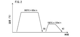
- FIG. 2 is a diagram showing heat patterns of quenching and tempering for test pieces for a hardenability evaluation test and a toughness evaluation test in Examples.
- FIG. 1 shows a bearing part (comparative example) obtained by quenching and tempering a steel material corresponding to SUJ2 defined in JIS G 4805 (2008), and the above chemical composition, and the formula (1) Carburizing the steel material of the present embodiment
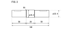
- FIG. 3 is a side view of an intermediate product of a small roller test piece used in the roller pitching test of the example.
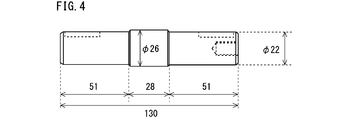
- FIG. 4 is a side view of a small roller test piece used in the roller pitching test of the example.
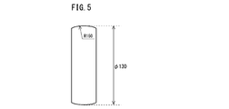
- FIG. 5 is a front view of a large roller used in the roller pitching test of the example.
- the present inventors have found that the machinability of a steel material as a raw material of a carbonitrided bearing part, and the wear resistance, the toughness of a core part, and the structure under a hydrogen generating environment in the carbonitrided bearing part after carbonitriding treatment.
- the peeling life due to the change was investigated and examined.
- the present inventors examined the chemical composition of the steel material to obtain the above-mentioned characteristics.
- C 0.15 to 0.45%
- Si 0.50% or less
- Mn 0.20 to 0.60%
- P 0.015% or less
- S 0.005 % Or less
- Cr 0.80 to 1.50%
- Mo 0.17 to 0.30%
- V 0.24 to 0.40%
- Al 0.005 to 0.100%
- N 0 0.0300% or less
- Ti 0 to 0.100%
- Ca 0 to 0.0010%
- a steel material having a chemical composition with the balance being Fe and impurities is used, machinability and carbonitrided bearing parts after carbonitriding treatment are used. It is considered that the abrasion resistance, the toughness of the core, and the peel
- V-carbide having a circle equivalent diameter of 150 nm or less In order to increase the peeling life of carbonitrided bearing parts in a hydrogen generation environment, in the carbonitrided bearing parts, V-carbide having a circle equivalent diameter of 150 nm or less, V-carbonitride having a circle equivalent diameter of 150 nm or less, and circle equivalent It is effective to generate a large number of one or more kinds selected from the group consisting of V-composite carbides having a diameter of 150 nm or less and V-composite carbonitrides having a circle equivalent diameter of 150 nm or less.
- the V composite carbide means a carbide containing V and Mo.
- the V composite carbonitride means a carbonitride containing V and Mo.
- V carbides and V carbonitrides are also referred to as “V carbides and the like”, and V composite carbides and V composite carbonitrides are referred to as “V composite carbides and the like”.
- V carbides and V composite carbides and the like V carbides and the like
- V carbides and V composite carbides and the like V carbides and the like
- a V carbide having a circle equivalent diameter of 150 nm or less is referred to as "small V carbide”
- a V composite carbide having a circle equivalent diameter of 150 nm or less is referred to as "small V composite carbide”.
- the equivalent circle diameter means the diameter of a circle having the same area as the area of V carbide or the like or V composite carbide or the like.
- the V carbide and the V composite carbide are small V carbides and the like having a circle equivalent diameter of 150 nm or less and the small V composite carbides, the small V carbides and the small V composite carbides trap hydrogen. Further, the small V carbide and the like and the small V composite carbide and the like are small in size, so that they are unlikely to be a starting point of cracking. Therefore, if the small V carbides and small V composite carbides are sufficiently dispersed in the carbonitrided bearing parts, it is difficult for the microstructure to change under the hydrogen generating environment, and as a result, the carbonitrided bearing parts under the hydrogen generating environment. The peeling life of can be increased.
- F1 is an index relating to the amount of small V carbides and the like, and small V composite carbides and the like that trap hydrogen and increase the peeling life of the carbonitrided bearing component under a hydrogen generating environment.
- the production of small V carbides and small V composite carbides is promoted by containing Cr and Mo as well as V.
- Cr produces Fe-based carbides such as cementite or Cr carbides in a temperature range lower than the temperature range in which V carbides and the like and V composite carbides and the like are generated.
- Mo produces Mo carbide (Mo 2 C) in a temperature range lower than the temperature range in which V carbide and the like and V composite carbide and the like are produced.
- Fe-based carbides, Cr-based carbides, and Mo-carbides form a solid solution to form precipitation nucleation sites for V-carbides and V-composite carbides.
- the equivalent circle diameter is V-carbides having a diameter of more than 150 nm and V-composite carbides having an equivalent circle diameter of more than 150 nm are produced.
- V-carbides having a circle equivalent diameter of more than 150 nm are also referred to as "coarse V carbides” and V-composite carbides having a circle-equivalent diameter of more than 150 nm are also referred to as "coarse V-composite carbides”.
- Coarse V carbides and coarse V composite carbides and the like have low ability to trap hydrogen, and are therefore likely to cause structural changes. Therefore, the coarse V carbide and the coarse V composite carbide reduce the peeling life of the carbonitrided bearing component under the hydrogen generation environment.
- F2 2.7C+0.4Si+Mn+0.45Ni+0.8Cr+Mo+V.
- Each element (C, Si, Mn, Ni, Cr, Mo and V) in F2 is a main element that enhances the hardenability of steel among the elements in the above chemical composition. Therefore, F2 is an index of the strength of the core of the carbonitrided bearing part and the machinability of the steel material.
- F2 is 2.20 or less, even if the content of each element in the chemical composition is within the range of the present embodiment and the formulas (1), (3) and (4) are satisfied, the steel material The hardenability of is not sufficient. Therefore, the strength of the core of the carbonitrided bearing component is not sufficient, and the peeling life of the carbonitrided bearing component in a hydrogen generating environment cannot be sufficiently obtained.
- F2 is 2.80 or more, even if the content of each element in the chemical composition is within the range of the present embodiment and the formulas (1), (3) and (4) are satisfied, However, the hardenability of steel becomes excessively high. In this case, sufficient machinability of the steel material cannot be obtained.
- F2 is higher than 2.20 and lower than 2.80, the content of each element in the chemical composition is within the range of the present embodiment, and the formula (1), the formula (3), and the formula (4) ) Is satisfied, sufficient machinability is obtained in the steel material. Further, the strength of the core portion of the carbonitrided bearing component is sufficiently increased, and the peeling life of the carbonitrided bearing component is sufficiently increased under the hydrogen generating environment.
- F3 Mo/V.
- F3 is less than 0.58, even if the content of each element in the chemical composition is within the range of the present embodiment and the formulas (1), (2) and (4) are satisfied, the size is small. V carbides and small V composite carbides are not sufficiently formed. As a result, the peeling life of the carbonitrided bearing component cannot be sufficiently obtained in the hydrogen generating environment. If F3 is 0.58 or more and the formula (3) is satisfied, the content of each element in the chemical composition is within the range of this embodiment, and the formula (1), the formula (2), and the formula (4) ) Is satisfied, small V carbides and the like and small V composite carbides and the like are sufficiently generated. As a result, the peeling life of the carbonitrided bearing component becomes sufficiently long under the hydrogen generation environment.
- F4 (Mo+V+Cr)/(Mn+20P).
- F4 is 2.40 or more, it is assumed that the content of each element in the chemical composition is within the range of the present embodiment and that the formulas (1) to (3) are satisfied, and the strengthening in the crystal grains is performed. A synergistic effect of the mechanism, the grain boundary strengthening mechanism, and the hydrogen invasion suppressing mechanism can be obtained, and the peeling life of the carbonitrided bearing component under a hydrogen generating environment can be sufficiently obtained.
- the ratio of the V content (mass %) in the electrolytic extraction residue of the steel material to the V content (mass %) in the chemical composition of the steel material is 10.0% or less.
- V carbides and V composite carbides should be as solid as possible in the steel material used for the carbonitrided bearing parts. It is preferable that it is melted. If V carbides, V composite carbides, etc. remain in the steel material, the V carbides, V composite carbides, etc. remaining in the steel material grow and coarsen during the carbonitriding bearing component manufacturing process. Coarse V carbides and coarse V composite carbides have a low ability to trap hydrogen during the use of carbonitrided bearing parts under a hydrogen generating environment.
- coarse V carbide and the like and coarse V composite carbide and the like are likely to cause a structural change during use of the carbonitrided bearing component in a hydrogen generating environment, and are also likely to be a starting point of cracking. Therefore, the peeling life of the carbonitrided bearing component is reduced.
- residue V amount ratio RA V defined in (A) is not more than 10.0%.
- RA V [V] R / [V] C ⁇ 100 (A) If the V content ratio RA V in the residue is 10.0% or less, V carbide and the like and V composite carbide and the like are sufficiently solid-dissolved in the steel material that is the material of the carbonitrided bearing component. Therefore, the reduction of the peeling life of the carbonitrided bearing component under the hydrogen generation environment due to the coarse V carbide and the like and the coarse V composite carbide and the like is suppressed.
- FIG. 1 shows a bearing component (comparative example) obtained by quenching and tempering a steel material corresponding to SUJ2 defined in JIS G 4805 (2008), and the above chemical composition, In a bearing component (carbonitrided bearing component: example of the present invention) manufactured by carbonitriding the steel material of the present embodiment satisfying (4) and having a V content ratio RA V in the residue of 10.0% or less.
- FIG. 3 is a diagram showing a stripping life under a hydrogen generation environment. The peeling life test under a hydrogen generating environment was carried out by the method described in Examples below.
- the vertical axis of FIG. 1 represents the ratio of the peeling life of each inventive example to the peeling life of the comparative example (hereinafter referred to as the peeling life ratio) when the peeling life of the comparative example is defined as 1.0 (reference). Show.
- the exfoliation life of a bearing component of a conventional chemical composition (comparative example) under a hydrogen generating environment is at least 2.0 times as long as the exfoliation life of the inventive example under a hydrogen generating environment. Is over.
- the peeling life of the carbonitrided bearing component manufactured using the steel material of the present embodiment under the hydrogen generating environment is extremely remarkably improved as compared with the conventional bearing component.
- the steel material that is the material of the carbonitrided bearing component according to the present embodiment completed based on the above knowledge has the following configuration.
- the chemical composition is In mass %, C: 0.15 to 0.45%, Si: 0.50% or less, Mn: 0.20-0.60%, P: 0.015% or less, S: 0.005% or less, Cr: 0.80 to 1.50%, Mo: 0.17 to 0.30%, V: 0.24 to 0.40%, Al: 0.005 to 0.100%, N: 0.0300% or less, O: 0.0015% or less, Cu: 0 to 0.20%, Ni: 0 to 0.20%, B: 0 to 0.0050%, Nb: 0-0.100%, Ti: 0 to 0.100%, Ca: 0 to 0.0010%, and
- the balance consists of Fe and impurities, Satisfying the formulas (1) to (4),
- the total area ratio of ferrite and pearlite in the microstructure is 10.0% or more, and the balance consists of bainite,
- the ratio of the V content (mass %) in the electrolytic extraction residue to the V content (mass %) in the chemical composition is 10.
- the steel material according to [1] The chemical composition is Cu: 0.01 to 0.20%, Ni: 0.01 to 0.20%, B: 0.0001 to 0.0050%, Nb: 0.005 to 0.100%, and Ti: 0.005 to 0.100%, containing one element or two or more elements selected from the group consisting of: Steel material.
- the steel material according to [1] or [2], The chemical composition is Ca: contains 0.0001 to 0.0010%, Steel material.
- the steel material of this embodiment is a raw material for carbonitrided bearing parts.
- the chemical composition of the steel material of this embodiment contains the following elements.
- C 0.15 to 0.45% Carbon (C) enhances the hardenability of steel. Therefore, the strength of the core portion and the toughness of the core portion of the carbonitrided bearing component manufactured using the steel material of the present embodiment as the raw material are increased. C further forms fine carbides and carbonitrides by carbonitriding to enhance the wear resistance of carbonitrided bearing components. Furthermore, C mainly forms small V carbides and small V composite carbides during carbonitriding. Small V carbides and small V composite carbides trap hydrogen in steel during the use of carbonitrided bearing parts in a hydrogen generating environment. Therefore, the small V carbide and the small V composite carbide increase the peeling life of the carbonitrided bearing component under the hydrogen generation environment.
- the C content is less than 0.15%, the above effects cannot be sufficiently obtained even if the content of other elements in the chemical composition is within the range of this embodiment.
- the C content exceeds 0.45%, even if the content of other elements is within the range of the present embodiment, V carbides, V composite carbides, etc. are not completely dissolved in the steel material manufacturing process. Remains in. The remaining V carbides and V composite carbides do not form a solid solution sufficiently in the manufacturing process of carbonitrided bearing parts. Then, the V carbides and V composite carbides and the like remaining in the steel material grow during the manufacturing process of the carbonitrided bearing component and remain as coarse V carbides and V composite carbides and the like in the carbonitrided bearing component.
- the C content is 0.15 to 0.45%.
- the preferable lower limit of the C content is 0.16%, more preferably 0.17%, and further preferably 0.18%.
- the preferable upper limit of the C content is 0.40%, more preferably 0.35%, and further preferably 0.32%.
- Si Silicon
- Si is inevitably contained. That is, the Si content is more than 0%. Si enhances the hardenability of the steel material, and further forms a solid solution with the ferrite of the steel material to strengthen the ferrite. This increases the strength of the core of the carbonitrided bearing component.
- the Si content is 0.50% or less.
- the preferable lower limit of the Si content is 0.01%, more preferably 0.02%, and further preferably 0.05%.
- the preferable upper limit of the Si content is 0.40%, more preferably 0.35%, further preferably 0.32%, and further preferably 0.30%.
- Mn 0.20-0.60%
- Manganese (Mn) enhances the hardenability of steel materials. As a result, the strength of the core of the carbonitrided bearing component is increased, and the peeling life of the carbonitrided bearing component in a hydrogen generating environment is increased. If the Mn content is less than 0.20%, the above effects cannot be sufficiently obtained even if the content of other elements is within the range of this embodiment. On the other hand, if the Mn content exceeds 0.60%, the hardness of the steel material becomes too high and the machinability of the steel material deteriorates, even if the content of other elements is within the range of this embodiment.
- the Mn content is 0.20 to 0.60%.
- the preferable lower limit of the Mn content is 0.22%, more preferably 0.24%, and further preferably 0.26%.
- the preferable upper limit of the Mn content is 0.55%, more preferably 0.50%, and further preferably 0.45%.
- Phosphorus (P) is an unavoidable impurity. That is, the P content is more than 0%. P segregates at the grain boundaries and reduces the grain boundary strength. If the P content exceeds 0.015%, even if the content of other elements is within the range of the present embodiment, P is excessively segregated at the grain boundaries to lower the grain boundary strength. As a result, the peeling life of the carbonitrided bearing component in a hydrogen generating environment is reduced. Therefore, the P content is 0.015% or less.
- the upper limit of the P content is preferably 0.013%, more preferably 0.010%. It is preferable that the P content is as low as possible. However, excessive reduction of P content raises manufacturing cost. Therefore, in consideration of normal industrial production, the lower limit of the P content is preferably 0.001%, and more preferably 0.002%.
- S 0.005% or less Sulfur (S) is an unavoidable impurity. That is, the S content is more than 0%. S produces sulfide-based inclusions. Coarse sulfide-based inclusions are likely to be the starting point of cracking during the use of carbonitrided bearing parts in a hydrogen generating environment. If the S content exceeds 0.005%, even if the content of other elements is within the range of the present embodiment, the sulfide-based inclusions become coarse, and the carbonitrided bearing component peels off in a hydrogen generating environment. The life is shortened. Therefore, the S content is 0.005% or less.
- the preferable upper limit of the S content is 0.004%, and more preferably 0.003%. It is preferable that the S content is as low as possible. However, excessive reduction of S content raises manufacturing cost. Therefore, in consideration of ordinary industrial production, the lower limit of the S content is preferably 0.001%, more preferably 0.002%.
- Chromium (Cr) enhances the hardenability of steel materials. This increases the strength of the core of the carbonitrided bearing component. Cr is further contained in combination with V and Mo to promote generation of small V carbides and small V composite carbides during carbonitriding. As a result, not only the wear resistance of the carbonitrided bearing component but also the peeling life of the carbonitrided component in a hydrogen generating environment is increased. If the Cr content is less than 0.80%, the above effect cannot be sufficiently obtained. On the other hand, if the Cr content exceeds 1.50%, the carburizing property at the time of carbonitriding treatment deteriorates even if the content of other elements is within the range of this embodiment.
- the Cr content is 0.80 to 1.50%.
- the preferable lower limit of the Cr content is 0.85%, more preferably 0.88%, and further preferably 0.90%.
- the preferable upper limit of the Cr content is 1.45%, more preferably 1.40%, and further preferably 1.35%.
- Mo 0.17 to 0.30% Molybdenum (Mo), like Cr, enhances the hardenability of steel materials. This increases the strength of the core of the carbonitrided bearing component. Mo is further contained in combination with V and Cr to promote generation of small V carbides and small V composite carbides during carbonitriding. As a result, not only the wear resistance of the carbonitrided bearing component but also the peeling life of the carbonitrided bearing component in a hydrogen generating environment is increased. If the Mo content is less than 0.17%, the above effect cannot be sufficiently obtained. On the other hand, if the Mo content exceeds 0.30%, the strength of the steel material becomes too high. In this case, the machinability of the steel material decreases.
- the Mo content is 0.17 to 0.30%.
- the preferable lower limit of the Mo content is 0.18%, more preferably 0.19%, and further preferably 0.20%.
- the preferable upper limit of the Mo content is 0.29%, more preferably 0.28%, and further preferably 0.27%.
- V 0.24 to 0.40% Vanadium (V) forms small V carbides and small V composite carbides and the like in the process of manufacturing carbonitrided bearing parts using steel.
- the small V carbides and the small V composite carbides trap hydrogen that has entered the carbonitrided bearing components during use of the carbonitrided bearing components in a hydrogen generating environment.
- the equivalent circle diameter of small V carbides and small V composite carbides in carbonitrided bearing parts is as small as 150 nm or less. Therefore, even if small V carbides and small V composite carbides trap hydrogen, they are unlikely to be the starting points of structural changes. Therefore, the peeling life of the carbonitrided bearing component in a hydrogen generating environment is increased.
- V further forms small V carbides and small V composite carbides in the manufacturing process of carbonitrided bearing parts to enhance the wear resistance of carbonitrided bearing parts. If the V content is less than 0.24%, the above effect cannot be sufficiently obtained. On the other hand, if the V content exceeds 0.40%, even if the content of other elements is within the range of the present embodiment, V carbides and V composite carbides are not completely dissolved in the steel material manufacturing process. To remain. The remaining V carbides and V composite carbides, etc. do not dissolve sufficiently in the manufacturing process of carbonitrided bearing parts, and grow during the manufacturing process of carbonitrided bearing parts to form coarse V carbides and coarse V composite carbides.
- V carbides and coarse V composite carbides reduce the toughness of the core of carbonitrided bearing parts. Further, the coarse V carbide and the like and the coarse V composite carbide and the like in the carbonitrided bearing component have a low ability to trap hydrogen. Therefore, the coarse V-carbide and the coarse V-composite carbide are likely to cause a structural change during the use of the carbonitrided bearing component under the hydrogen generation environment. Coarse V carbides and coarse V composite carbides also serve as crack initiation points. Therefore, the coarse V carbide and the coarse V composite carbide reduce the peeling life of the carbonitrided bearing part under the hydrogen generation environment. Therefore, the V content is 0.24 to 0.40%. The preferable lower limit of the V content is 0.25%, more preferably 0.26%, and further preferably 0.27%. The preferable upper limit of the V content is 0.39%, more preferably 0.38%, and further preferably 0.36%.
- Al 0.005 to 0.100%
- Aluminum (Al) deoxidizes steel. If the Al content is less than 0.005%, the above effect cannot be sufficiently obtained even if the content of other elements is within the range of this embodiment. On the other hand, if the Al content exceeds 0.100%, coarse oxide-based inclusions are generated even if the content of other elements is within the range of this embodiment. Coarse oxide-based inclusions are the starting point for fatigue failure of carbonitrided bearing parts under hydrogen generation environment. Therefore, the peeling life of the carbonitrided bearing component in a hydrogen generating environment is shortened. Therefore, the Al content is 0.005 to 0.100%.
- the preferable lower limit of the Al content is 0.008%, more preferably 0.010%.
- the preferable upper limit of the Al content is 0.080%, more preferably 0.070%, further preferably 0.060%.
- the Al content as used herein means the content of total Al (Total Al).
- N 0.0300% or less Nitrogen (N) is an unavoidable impurity. That is, the N content is more than 0%. N forms a solid solution in the steel material and reduces the hot workability of the steel material. If the N content exceeds 0.0300%, the hot workability of the steel material is significantly reduced. Therefore, the N content is 0.0300% or less.
- the preferable upper limit of the N content is 0.0250%, more preferably 0.0200%, further preferably 0.0150%, further preferably 0.0130%.
- the N content is preferably as low as possible. However, excessive reduction of N content raises manufacturing costs. Therefore, in consideration of ordinary industrial production, the lower limit of the N content is preferably 0.0001%, and more preferably 0.0002%.
- Oxygen (O) is an impurity that is inevitably contained. That is, the O content is more than 0%. O combines with other elements in the steel to form coarse oxide-based inclusions. Coarse oxide-based inclusions are the starting point for fatigue failure of carbonitrided bearing parts under hydrogen generation environment. Therefore, the peeling life of the carbonitrided bearing component in a hydrogen generating environment is shortened. When the O content exceeds 0.0015%, the peeling life of the carbonitrided bearing component in a hydrogen generating environment is significantly reduced even if the content of other elements is within the range of this embodiment. Therefore, the O content is 0.0015% or less.
- the preferable upper limit of the O content is 0.0013%, and more preferably 0.0012%.
- the O content is preferably as low as possible. However, excessive reduction of O content raises manufacturing cost. Therefore, in consideration of ordinary industrial production, the lower limit of the O content is preferably 0.0001%, and more preferably 0.0002%.
- the balance of the chemical composition of the steel material according to this embodiment is Fe and impurities.
- the impurities are those that are mixed from the ore as a raw material, scrap, or the manufacturing environment when the steel material is industrially manufactured, and are allowed within a range that does not adversely affect the steel material of the present embodiment. Means what is done.
- the chemical composition of the steel material of the present embodiment may further contain one kind or two or more kinds selected from the group consisting of Cu, Ni, B, Nb and Ti, instead of part of Fe. These elements are optional elements, and all increase the strength of the carbonitrided bearing component.
- Cu 0 to 0.20%
- Copper (Cu) is an optional element and may not be contained. That is, the Cu content may be 0%.
- Cu enhances the hardenability of the steel material. This increases the strength of the steel material and the strength of the core of the carbonitrided bearing component. If Cu is contained even a little, the above effect can be obtained to some extent. However, if the Cu content exceeds 0.20%, the strength of the steel material excessively increases and the machinability of the steel material deteriorates even if the content of other elements is within the range of this embodiment. Therefore, the Cu content is 0 to 0.20%.
- the preferable lower limit of the Cu content is more than 0%, more preferably 0.01%, further preferably 0.02%, further preferably 0.03%, further preferably 0.05%. Is.
- the preferable upper limit of the Cu content is 0.18%, more preferably 0.16%, and further preferably 0.15%.
- Nickel (Ni) is an optional element and may not be contained. That is, the Ni content may be 0%. When contained, Ni enhances the hardenability of the steel material. This increases the strength of the steel material and the strength of the core of the carbonitrided bearing component. If Ni is contained even a little, the above effect can be obtained to some extent. However, if the Ni content exceeds 0.20%, the strength of the steel material excessively increases and the machinability of the steel material deteriorates even if the content of other elements is within the range of this embodiment. Therefore, the Ni content is 0 to 0.20%.
- the preferable lower limit of the Ni content is more than 0%, more preferably 0.01%, further preferably 0.02%, further preferably 0.03%, further preferably 0.05%. Is.
- the preferable upper limit of the Ni content is 0.18%, more preferably 0.16%, and further preferably 0.15%.
- B 0 to 0.0050%
- Boron (B) is an optional element and may not be contained. That is, the B content may be 0%. When contained, B enhances the hardenability of the steel material. This increases the strength of the steel material and the strength of the core of the carbonitrided bearing component. B further suppresses P from segregating at the grain boundaries. If B is contained in even a small amount, the above effect can be obtained to some extent. However, if the B content exceeds 0.0050%, B nitride (BN) is generated and the toughness of the core portion of the carbonitrided bearing component is reduced. Therefore, the B content is 0 to 0.0050%.
- the preferable lower limit of the B content is more than 0%, more preferably 0.0001%, further preferably 0.0003%, further preferably 0.0005%, further preferably 0.0010%. Is.
- the preferable upper limit of the B content is 0.0030%, more preferably 0.0025%, and further preferably 0.0020%.
- Niobium (Nb) is an optional element and may not be contained. That is, the Nb content may be 0%. When contained, Nb combines with C and N in steel to form carbides, nitrides, and carbonitrides. These precipitates enhance the strength of carbonitrided bearing parts by precipitation strengthening. If Nb is contained even a little, the above effect can be obtained to some extent. However, if the Nb content exceeds 0.100%, the toughness of the core portion of the carbonitrided bearing component decreases. Therefore, the Nb content is 0 to 0.100%.
- the preferable lower limit of the Nb content is more than 0%, more preferably 0.005%, further preferably 0.010%.
- the preferable upper limit of the Nb content is 0.080%, more preferably 0.070%, further preferably 0.050%, further preferably 0.040%.
- Titanium (Ti) is an optional element and may not be contained. That is, the Ti content may be 0%. When included, Ti forms carbides, nitrides, and carbonitrides similar to Nb, increasing the strength of carbonitrided bearing components. If Ti is contained even a little, the above effect can be obtained to some extent. However, if the Ti content exceeds 0.100%, the toughness of the core portion of the carbonitrided bearing component decreases. Therefore, the Ti content is 0 to 0.100%.
- the preferable lower limit of the Ti content is more than 0%, more preferably 0.005%, further preferably 0.010%.
- the preferable upper limit of the Ti content is 0.080%, more preferably 0.070%, further preferably 0.050%, further preferably 0.040%.
- the chemical composition of the steel material of the present embodiment may further contain Ca instead of part of Fe.
- Ca 0 to 0.0010%
- Calcium (Ca) is an optional element and may not be contained. That is, the Ca content may be 0%. When contained, Ca forms a solid solution with the inclusions in the steel material to make the sulfide fine and spherical. In this case, the hot workability of the steel material is enhanced. If Ca is contained even in a small amount, the above effect can be obtained to some extent. However, if the Ca content exceeds 0.0010%, coarse oxide inclusions are formed in the steel material. If the coarse oxide-based inclusions trap hydrogen during the use of the carburized bearing component in a hydrogen generating environment, a microstructure change is likely to occur. The occurrence of structural change shortens the peeling life of carbonitrided bearing parts.
- the Ca content is 0 to 0.0010%.
- the preferable lower limit of the Ca content is more than 0%, more preferably 0.0001%, and further preferably 0.0003%.
- the preferable upper limit of the Ca content is 0.0009%, more preferably 0.0008%.
- the chemical composition of the steel material of the present embodiment further satisfies the following formulas (1) to (4). 1.50 ⁇ 0.4Cr+0.4Mo+4.5V ⁇ 2.45 (1) 2.20 ⁇ 2.7C+0.4Si+Mn+0.45Ni+0.8Cr+Mo+V ⁇ 2.80 (2) Mo/V ⁇ 0.58 (3) (Mo+V+Cr)/(Mn+20P) ⁇ 2.40 (4) Here, the content (mass %) of the corresponding element is substituted for each element symbol in the formulas (1) to (4).
- F1 is a small V carbide or the like (small V carbide or small V carbonitride) or a small V composite carbide (small V composite carbide or the like) that traps hydrogen and enhances the peeling life of the carbonitrided bearing component under a hydrogen generating environment. It is an index for the generation of small V composite carbonitrides. As described above, the generation of small V carbides and small V composite carbides is promoted by the inclusion of Cr and Mo as well as V. Cr produces Fe-based carbides such as cementite or Cr carbides in a temperature range lower than the temperature range in which V carbides and the like and V composite carbides and the like are generated.
- Mo produces Mo carbide (Mo 2 C) in a temperature range lower than the temperature range in which V carbide and the like and V composite carbide and the like are produced. As the temperature rises, Fe-based carbides, Cr-based carbides, and Mo-carbides form a solid solution to form precipitation nucleation sites for V-carbides and V-composite carbides.
- the V carbide and the like and the V composite carbide and the like remain in the steel material without sufficiently forming a solid solution. Therefore, in the manufacturing process of the carbonitrided bearing component, the V carbides and V composite carbides and the like remaining in the steel material grow to become coarse V carbides and coarse V composite carbides. Coarse V carbides and coarse V composite carbides have low hydrogen trapping ability. Therefore, the coarse V-carbide and the coarse V-composite carbide are likely to cause a structural change during the use of the carbonitrided bearing component under the hydrogen generation environment. Coarse V carbides and coarse V composite carbides also serve as crack initiation points. Therefore, the peeling life of the carbonitrided bearing component in a hydrogen generating environment is shortened.
- the preferable lower limit of F1 is 1.51, more preferably 1.52, further preferably 1.54, further preferably 1.55, and further preferably 1.56.
- the preferable upper limit of F1 is 2.44, more preferably 2.43, and further preferably 2.42.
- the value of F1 shall be the value obtained by rounding off the third decimal place.
- F2 is an index of the strength of the core of the carbonitrided bearing component.
- F2 is 2.20 or less, even if the content of each element in the chemical composition is within the range of the present embodiment and the formulas (1), (3) and (4) are satisfied, the steel material The hardenability of is not sufficient. Therefore, the strength of the core of the carbonitrided bearing component is not sufficient. In this case, the peeling life of the carbonitrided bearing component cannot be sufficiently obtained in the hydrogen generating environment.
- F2 is 2.80 or more, even if the content of each element in the chemical composition is within the range of the present embodiment and the formulas (1), (3) and (4) are satisfied, However, the hardenability of steel becomes excessively high. In this case, in the microstructure of the steel material, the total area ratio of ferrite and pearlite is less than 10.0%. Therefore, the machinability of the steel material cannot be sufficiently obtained.
- F2 is higher than 2.20 and lower than 2.80, the content of each element in the chemical composition is within the range of the present embodiment, and the formula (1), the formula (3), and the formula (4) ) Is satisfied, sufficient machinability is obtained in the steel material. Further, the strength of the core portion of the carbonitrided bearing component is sufficiently increased, and the peeling life of the carbonitrided bearing component is sufficiently increased under the hydrogen generating environment.
- the preferable lower limit of F2 is 2.23, more preferably 2.25, further preferably 2.30, further preferably 2.35, and further preferably 2.45.
- the preferable upper limit of F2 is 2.78, more preferably 2.75, further preferably 2.73, and further preferably 2.70.
- the value of F2 shall be the value obtained by rounding off the third decimal place.
- F3 Mo/V.
- the total V content, Cr content, and Mo content necessary for producing small V carbides and small V composite carbides are summed up. The content is obtained.
- F3 is 0.58 or more and the formula (3) is satisfied, the content of each element in the chemical composition is within the range of this embodiment, and the formula (1), the formula (2), and the formula (4) ) Is satisfied, small V carbides and small V composite carbides are sufficiently generated in the carbonitrided bearing component. As a result, the peeling life of the carbonitrided bearing component under hydrogen generating environment is sufficiently long.
- the preferable lower limit of F3 is 0.60, more preferably 0.65, further preferably 0.68, further preferably 0.70, further preferably 0.73, and further preferably It is 0.76.
- the value of F3 shall be the value obtained by rounding off the third decimal place.
- F4 (Mo+V+Cr)/(Mn+20P).
- Small V carbides and small V composite carbides not only trap hydrogen but also strengthen the inside of crystal grains by precipitation strengthening.
- (a) intra-grain strengthening (b) crystal grain boundary strengthening, (c) Due to the three synergistic effects of suppressing hydrogen invasion, the peeling life of carbonitrided bearing parts in a hydrogen generating environment is further extended.
- the intra-grain strengthening of (a) depends on the total content of Mo content, V content, and Cr content as described above.
- F4 is 2.40 or more, it is assumed that the content of each element in the chemical composition is within the range of the present embodiment and that the formulas (1) to (3) are satisfied, and the strengthening in the crystal grains is performed. A synergistic effect of the mechanism, the grain boundary strengthening mechanism, and the hydrogen invasion suppressing mechanism can be obtained, and the peeling life of the carbonitrided bearing component under a hydrogen generating environment can be sufficiently obtained.
- the preferable lower limit of F4 is 2.42, more preferably 2.45, further preferably 2.47, further preferably 2.50, and further preferably 2.52.
- the value of F4 shall be the value obtained by rounding off the third decimal place.
- the microstructure of the steel material of the present embodiment means a structure in which the total area ratio of ferrite and pearlite is 10.0% or more and the balance is bainite.
- the C content in the chemical composition is low, in the microstructure of the steel material of the present embodiment, the total area ratio of ferrite and pearlite is 50.0% or more, and the balance is bainite.
- the C content in the chemical composition is high, in the microstructure of the steel material of the present embodiment, the area ratio of bainite is 50.0% or more, and the balance consists of ferrite and pearlite.
- the total area ratio of ferrite and pearlite is at least 10.0% or more, and the balance consists of bainite.
- the preferable total area ratio of ferrite and pearlite is 10.0 to 90.0%, and the balance is bainite.
- the preferable upper limit of the total area ratio of ferrite and pearlite is 80.0%, and more preferably 78.0%.
- the preferred lower limit of ferrite and pearlite is 20.0%, more preferably 25.0%.
- regions other than bainite, ferrite and pearlite are, for example, retained austenite, precipitates (including cementite) and inclusions, but the total austenite, precipitates and inclusions in the microstructure are The area ratio is so small that it can be ignored.
- the total area ratio (%) of ferrite and pearlite and the area ratio (%) of bainite in the microstructure of the steel material of this embodiment are measured by the following method.
- a sample is taken from the center position (R/2 position) of the radius R connecting the surface and the central axis in the cross section (hereinafter referred to as the cross section) perpendicular to the longitudinal direction (axial direction) of the steel bar or the steel material which is the wire rod. ..
- the surface corresponding to the above-mentioned cross section is the observation surface.
- the observation surface is etched using 2% nitric acid alcohol (nital etchant). The etched observation surface is observed using a 500 ⁇ optical microscope, and a photographic image of arbitrary 20 fields of view is generated. The size of each visual field is 100 ⁇ m ⁇ 100 ⁇ m.
- each phase is specified based on the contrast.
- the total area ([mu] m 2) of the ferrite in each field and determines the total area of perlite ( ⁇ m 2).
- the ratio of the total area of the total area of ferrite and the total area of pearlite in all the visual fields to the total area of all the visual fields is defined as the total area ratio (%) of ferrite and pearlite.
- the total area ratio (%) of ferrite and pearlite is a value obtained by rounding the second decimal place.
- V carbide and the like and V composite carbide and the like are sufficiently dissolved, and the residual amount of V carbide and the like and V composite carbide and the like is sufficiently low.
- the residue V amount ratio RA V defined by formula (A) is not more than 10.0%.
- residue V amount ratio RA V exceeds 10.0%, the steel, V carbides and V composite carbides are not sufficiently dissolved.
- the V carbides and V composite carbides remaining in the steel material grow to become coarse V carbides and coarse V composite carbides. ..
- Coarse V carbides and coarse V composite carbides have low hydrogen trapping ability. Therefore, the coarse V carbide and the coarse V composite carbide and the like are likely to cause a structural change during the use of the carbonitrided bearing component in a hydrogen generating environment. If the microstructure is changed, the peeling life of the carbonitrided bearing part in a hydrogen generating environment is shortened.
- the preferable upper limit of the residue V amount ratio RA V is 9.5%, more preferably 9.2%, more preferably 9.0%, more preferably 8.5%, more preferably Is 8.3%, more preferably 8.0%, further preferably 7.5%, further preferably 7.0%, further preferably 6.5%, and further preferably Is 6.0%.
- the V content in the electrolytic extraction residue of the steel material of this embodiment can be measured by the following method. First, the precipitates and inclusions in the steel material are captured as a residue. A cylindrical test piece having a diameter of 6 mm and a length of 50 mm is taken from the steel material. Specifically, three cylindrical test pieces are sampled from the R/2 position of a cross section (hereinafter referred to as a cross section) perpendicular to the longitudinal direction (axial direction) of the steel material. The surface of the sampled cylindrical test piece is polished by preliminary electrolytic polishing to about 50 ⁇ m to obtain a new surface.
- a cross section perpendicular to the longitudinal direction (axial direction) of the steel material.
- the electrolytically polished cylindrical test piece is electrolyzed with an electrolytic solution (10% acetylacetone+1% tetraammonium+methanol).
- the electrolytic solution after electrolysis is filtered through a 0.2 ⁇ m filter to capture the residue.
- the obtained electrolysis extraction residue is acid-decomposed and ICP (inductively coupled plasma) emission analysis is performed to quantify the V content in the electrolysis extraction residue when the steel material (base material) is 100 mass %.
- the arithmetic mean value of V content in the electrolytic extraction residue of each columnar test piece (that is, the arithmetic mean value of three V contents) is defined as V content [V] R in the electrolytic extraction residue of steel.
- V content [V] R in the electrolytic extraction residue is a value obtained by rounding off the second decimal place of the arithmetic mean value.
- Residue V amount ratio RA V is a value obtained by rounding off to one decimal place.
- RA V [V] R / [V] C ⁇ 100 (A)
- the content of each element is within the range of the present embodiment described above, and F1 to F4 satisfy the formulas (1) to (4).
- the microstructure comprising a ferrite and a total area ratio of pearlite of 10.0% or more balance being bainite, further residue V amount ratio RA V is less than or equal to 10.0%. Therefore, the steel material of this embodiment is excellent in machinability. Furthermore, after performing hot forging treatment on the steel material of the present embodiment, in a carbonitrided bearing component obtained by carbonitriding treatment, excellent wear resistance and excellent toughness of the core portion are obtained, and further, Excellent peeling life is obtained for carbonitrided bearing parts under hydrogen generation environment.
- the method for manufacturing a steel material described below is an example for manufacturing a steel material that is a raw material for the carbonitrided bearing component of the present embodiment. Therefore, the steel material having the above configuration may be manufactured by a manufacturing method other than the manufacturing method described below. However, the manufacturing method described below is a preferred example of the method for manufacturing the steel material of the present embodiment.
- An example of the method for manufacturing a steel material according to the present embodiment includes a steelmaking step of refining molten steel and casting the material (cast slab), and a hot working step of hot working the material to produce a steel material. ..
- a steelmaking step of refining molten steel and casting the material (cast slab) and a hot working step of hot working the material to produce a steel material. ..
- each step will be described.
- Step making process In the steelmaking process, first, molten steel having the above chemical composition in which the content of each element is within the range of the present embodiment and F1 to F4 satisfy the formulas (1) to (4) is manufactured.
- the refining method is not particularly limited, and a known method may be used.
- refining (primary refining) in a converter is performed on the hot metal produced by a known method.
- the well-known secondary refining is performed on the molten steel tapped from the converter.
- addition of alloying elements for component adjustment is performed, and the content of each element is within the range of this embodiment, and F1 to F4 are chemical compositions satisfying formulas (1) to (4).
- the raw material is manufactured by the well-known casting method using the molten steel manufactured by the above refining method.
- molten steel is used to produce an ingot by the ingot making method.
- bloom or billet may be manufactured by continuous casting method using molten steel.
- the material (bloom, ingot) is manufactured by the above method.
- the material (bloom or ingot) manufactured in the steel manufacturing step is subjected to hot working to manufacture a steel material.
- the steel material is a steel bar or a wire rod.
- the hot working process includes a rough rolling process and a finish rolling process.
- the material is hot worked to produce a billet.
- the rough rolling process uses, for example, a slab mill.
- the slab is rolled by a slab to produce a billet.
- a continuous rolling mill is installed downstream of the slab, the bilge-rolled billet is further hot-rolled using a continuous rolling mill to produce a smaller billet. May be.
- a horizontal stand having a pair of horizontal rolls and a vertical stand having a pair of vertical rolls are alternately arranged in a line.
- the heating temperature and holding time in the heating furnace in the rough rolling process are as follows. Heating temperature: 1150 to 1300°C Holding time at the heating temperature: 1.5 to 10.0 hours
- the heating temperature is the furnace temperature (° C.) of the heating furnace.
- the holding time is the holding time (hour) when the furnace temperature of the heating furnace is 1150 to 1300°C.
- the heating temperature is less than 1150° C. or the holding time at the heating temperature of 1150 to 1300° C. is less than 1.5 hours, the V carbides and V composite carbides in the raw material will not be sufficiently dissolved. Therefore, the residue V amount ratio RA V in the steel exceeds 10.0%.
- the heating temperature exceeds 1300° C. or the holding time at 1150 to 1300° C. exceeds 10.0 hours, the unit consumption becomes excessively high and the manufacturing cost becomes high.
- the heating temperature in the rough rolling step is 1150 to 1300°C and the holding time at 1150 to 1300°C is 1.5 to 10.0 hours, the V carbides and V composite carbides in the material are sufficient. Dissolve in.
- the billet is first heated using a heating furnace.
- the billet after heating is hot-rolled using a continuous rolling mill to manufacture a steel bar or a wire rod.
- the heating temperature and holding time in the heating furnace in the finish rolling process are as follows. Heating temperature: 1150 to 1300°C Holding time at the heating temperature: 1.5 to 5.0 hours
- the heating temperature is the furnace temperature (° C.) of the heating furnace.
- the holding time is the holding time (hour) when the furnace temperature of the heating furnace is 1150 to 1300°C.
- the heating temperature in the heating furnace in the finish rolling process is less than 1150°C or the holding time at 1150 to 1300°C is less than 1.5 hours, the load applied to the rolling mill during finish rolling becomes excessively large. .. On the other hand, if the heating temperature exceeds 1300° C. or the holding time at 1150 to 1300° C. exceeds 5.0 hours, the unit consumption becomes excessively high and the manufacturing cost becomes high.
- the heating temperature in the finish rolling step is 1150 to 1300° C. and the holding time at 1150 to 1300° C. is 1.5 to 5.0 hours, V carbides and V composite carbides in the material Dissolve sufficiently.
- the steel material after finish rolling is cooled at a cooling rate equal to or lower than cooling to manufacture the steel material of this embodiment.
- the average cooling rate CR in the temperature range where the steel material temperature is 800°C to 500°C is 0.1 to 5.0°C/sec.
- a phase transformation from austenite to ferrite, pearlite, or bainite occurs.
- the microstructure has a total area ratio of ferrite and pearlite of 10.0% or more. Yes, and the balance consists of bainite.
- the average cooling rate CR is measured by the following method.
- the steel material after finish rolling is conveyed downstream in the conveying line.
- a plurality of thermometers are arranged along the transfer line, and the steel material temperature at each position of the transfer line can be measured. Based on a plurality of thermometers arranged along the transfer line, the time until the temperature of the steel material reaches 800°C to 500°C is obtained, and the average cooling rate CR (°C/sec) is obtained.
- the average cooling rate CR can be adjusted by disposing a plurality of slow cooling covers at intervals on the transfer line.
- the steel material of this embodiment having the above-mentioned configuration can be manufactured by the above manufacturing process.
- the steel material of this embodiment is used for carbonitriding bearing parts.
- the carbonitrided bearing component means a bearing component that has been carbonitrided.
- the carbonitriding treatment means a treatment for performing carbonitriding quenching and tempering.
- Bearing parts mean parts of rolling bearings.
- the bearing component is, for example, a bearing ring, a bearing washer, a rolling element, or the like.
- the bearing ring may be an inner ring or an outer ring, and the bearing washer may be an axial bearing washer, a housing bearing washer, a central bearing washer, or a centering housing bearing washer.
- the bearing ring and the bearing washer are not particularly limited as long as they are members having a raceway surface.
- the rolling elements may be balls or rollers.
- the rollers are, for example, cylindrical rollers, rod rollers, needle rollers, tapered rollers, convex rollers and the like.
- the carbonitrided bearing part includes a carbonitrided layer formed on the surface layer by carbonitriding treatment, and a core portion inside the carbonitrided layer.
- the depth of the carbonitriding layer is not particularly limited, but the depth from the surface of the carbonitriding layer is, for example, 0.2 mm to 5.0 mm.
- the chemical composition of the core portion is the same as the chemical composition of the steel material of this embodiment.
- An example of the method for manufacturing the carbonitrided bearing component having the above-described configuration is as follows. First, an intermediate product is manufactured by processing the steel material of the present embodiment, which is a raw material for carbonitrided bearing parts, into a predetermined shape.
- the processing method is, for example, hot forging or machining.
- the machining is, for example, cutting. It suffices to carry out the hot forging under known conditions.
- the heating temperature of the steel material in the hot forging step is, for example, 1000 to 1300°C.
- the intermediate product after hot forging is allowed to cool. In addition, you may implement a machining process after hot forging.
- a well-known spheroidizing annealing treatment may be performed on the steel material or the intermediate product before performing the machining process.
- machining it is preferable that the machinability of the steel material (intermediate product) is high.
- the steel material of this embodiment has excellent machinability. Therefore, the steel material of the present embodiment is suitable for the machining process.
- Carbonitriding is performed on the manufactured intermediate product to manufacture a carbonitrided bearing component.
- the carbonitriding treatment includes carbonitriding and quenching and tempering as described above.
- carbonitriding and quenching an intermediate product is heated and held at a carbonitriding temperature of Ac 3 transformation point or higher in a known atmosphere gas containing ammonia gas in a known carburization conversion gas, and then rapidly cooled.
- the tempering treatment the carbonitrided intermediate product is held at a tempering temperature of 100 to 500° C. for a predetermined time.
- the carburizing shift gas means a well-known endothermic shift gas (RX gas).
- the RX gas is a gas obtained by mixing a hydrocarbon gas such as butane and propane with air and allowing the mixture to pass through a heated Ni catalyst to cause a reaction, and is a mixed gas containing CO, H 2 , N 2, and the like.
- the surface C concentration, surface N concentration, and surface hardness of carbonitrided bearing parts can be adjusted by controlling the conditions of carbonitriding and quenching and tempering. Specifically, the surface C concentration and the surface N concentration are adjusted by controlling the carbon potential and the ammonia concentration in the atmosphere gas during carbonitriding and quenching.
- the surface C concentration of carbonitrided bearing parts is mainly adjusted by the carbon potential of carbonitriding and quenching, the carbonitriding temperature, and the holding time at the carbonitriding temperature.
- the lower the carbon potential, the lower carbonitriding temperature, and the shorter the holding time at the carbonitriding temperature the lower the surface C concentration becomes.
- the surface N concentration is mainly adjusted by the ammonia concentration during carbonitriding and quenching, the carbonitriding temperature, and the holding time at the carbonitriding temperature.
- the lower the ammonia concentration, the higher the carbonitriding temperature, and the shorter the holding time at the carbonitriding temperature the lower the surface N concentration.
- Surface hardness is related to surface C concentration and surface N concentration. Specifically, the higher the surface C concentration and the surface N concentration, the higher the surface hardness. On the other hand, when the surface C concentration and the surface N concentration decrease, the surface hardness also decreases.
- the surface hardness increased by carbonitriding and quenching can be reduced by tempering. If the tempering temperature is high and the holding time at the tempering temperature is long, the surface hardness of the carbonitrided part decreases. If the tempering temperature is low and the holding time at the tempering temperature is short, the surface hardness of the carbonitrided part can be maintained high.
- Carbon potential CP in atmospheric gas 0.70 to 1.40
- the carbon potential CP in the atmospheric gas is 0.70 or more
- the C concentration on the surface of the carbonitrided bearing component is sufficiently increased, and for example, the surface C concentration is 0.70% or more by mass %.
- the carbonitriding treatment produces a sufficient amount of carbonitrides, and the wear resistance is remarkably enhanced.
- the carbon potential CP is 1.40 or less
- the surface C concentration becomes 1.20% or less, and the generation of coarse carbonitride can be sufficiently suppressed. Therefore, the preferable carbon potential CP is 0.70 to 1.40.
- Ammonia concentration with respect to carburizing shift gas flow rate in the atmosphere 1.00 to 6.00%
- the ammonia concentration with respect to the flow rate of the carburizing shift gas in the atmosphere means the ammonia concentration (mass %) when the flow rate of the carburizing shift gas is 100%.
- the ammonia concentration with respect to the flow rate of the carburized and transformed gas is 1.00% or more
- the surface N concentration of the carbonitrided bearing component is sufficiently increased and the surface N concentration is 0.15% or more. In this case, the carbonitriding treatment produces a sufficient amount of carbonitrides, and the wear resistance is remarkably enhanced.
- the ammonia concentration with respect to the flow rate of the carburized shift gas is 6.00% or less, the surface N concentration of the carbonitrided bearing component will be 0.60% or less. In this case, the formation of coarse carbonitride is sufficiently suppressed. Therefore, the ammonia concentration is 1.00 to 6.00% with respect to the flow rate of the carburizing shift gas in the atmosphere.
- Holding temperature during carbonitriding (carbonitriding temperature): 830 to 930°C Holding time at carbonitriding temperature: 30 to 100 minutes If the carbonitriding temperature is too low, the diffusion rate of C and N becomes slow. In this case, the processing time required to obtain a predetermined heat treatment property becomes long and the manufacturing cost becomes high. On the other hand, if the carbonitriding temperature is too high, ammonia in the atmosphere is decomposed, and the amount of N penetrating into the steel material decreases. Furthermore, the amount of invaded C and N in solid solution in the steel material matrix increases. Therefore, a sufficient amount of carbonitride is not generated, and the wear resistance of the carbonitrided bearing part is reduced. Therefore, the carbonitriding temperature is 830 to 930°C.
- the holding time at the carbonitriding temperature is not particularly limited as long as a sufficient C concentration and N concentration can be secured on the surface of the steel material.
- the holding time is, for example, 30 to 100 minutes.
- Quenching temperature 830-930°C If the quenching temperature is too low, sufficient C cannot be solid-dissolved in the steel, and the hardness of the steel will decrease. On the other hand, if the quenching temperature is too high, the crystal grains become coarse, and coarse carbonitrides along the grain boundaries are likely to precipitate. Therefore, the quenching temperature is 830 to 930°C.
- the carbonitriding temperature may also serve as the carburizing and quenching temperature.
- Tempering temperature 150 ⁇ 200°C Holding time at tempering temperature: 30 to 240 minutes If the tempering temperature is too low, sufficient toughness of the core of the carbonitrided bearing component cannot be obtained. On the other hand, if the tempering temperature is too high, the surface hardness of the carbonitrided bearing component decreases, and the wear resistance of the carbonitrided bearing component decreases. Therefore, the tempering temperature is 150 to 200°C.
- the holding time at the tempering temperature is 30 to 240 minutes.
- C concentration, N concentration and Rockwell C hardness on the surface of carbonitrided bearing parts The C concentration, N concentration and Rockwell C hardness HRC on the surface of the carbonitrided bearing component manufactured by the above manufacturing process are as follows.
- the carbon concentration of the surface of the carbonitrided bearing component produced by carbonitriding and tempering the steel material of the present embodiment under the above conditions is 0.7 to 1.2%. If the C concentration on the surface is too low, the surface hardness will be too low and the wear resistance will be reduced. On the other hand, if the C concentration on the surface is too high, coarse carbides, coarse carbonitrides, and the like are generated, and the stripping life in a hydrogen generation environment is reduced. When the C concentration on the surface is 0.70 to 1.20%, the abrasion resistance and the peeling life in a hydrogen generating environment are excellent.
- the lower limit of the C concentration on the surface is preferably 0.75%, more preferably 0.80%.
- the preferable upper limit of the C concentration on the surface is 1.10%, more preferably 1.05%, and further preferably 1.00%.
- the N concentration on the surface of the carbonitrided bearing component produced by carbonitriding and quenching and tempering the steel material of the present embodiment under the above conditions is 0.15 to 0.60%. If the N concentration on the surface is too low, the generation of fine carbonitrides is suppressed, so that the wear resistance of the carbonitrided bearing component is reduced. On the other hand, if the N concentration on the surface is too high, an excessive amount of retained austenite is produced. In this case, the hardness of the surface of the carbonitrided bearing component decreases, and the peeling life in a hydrogen generating environment decreases.
- the carbonitrided bearing component is excellent in wear resistance and peeling life under a hydrogen generating environment.
- the preferable lower limit of the N concentration on the surface is 0.18%, more preferably 0.20%.
- the preferable upper limit of the N concentration on the surface is 0.58%, more preferably 0.56%, and further preferably 0.54%.
- the C concentration and N concentration on the surface are measured by the following methods.
- An electron beam microanalyzer (EPMA) is used to measure the C and N concentrations at an arbitrary surface position of the carbonitrided bearing component up to a depth of 100 ⁇ m at a pitch of 1.0 ⁇ m.
- the arithmetic mean value of the measured C concentration is defined as the surface C concentration (mass %).
- the arithmetic mean value of the measured N concentrations is defined as the surface N concentration (mass %).
- the surface of the carbonitrided bearing component has a Rockwell C hardness HRC of 58 to 65.
- the Rockwell C hardness HRC of the surface is less than 58, the wear resistance of the carbonitrided bearing component is deteriorated.
- the Rockwell C hardness of the surface exceeds 65, the generation and propagation of fine cracks are facilitated, and the peeling life in a hydrogen generating environment is shortened.
- the Rockwell C hardness of the surface is 58 to 65, excellent abrasion resistance and excellent peeling life under hydrogen generating environment can be obtained.
- the preferable lower limit of the Rockwell C hardness of the surface is 59.
- the preferable upper limit of the Rockwell C hardness of the surface is 64.
- the Rockwell C hardness HRC of carbonitrided bearing parts is measured by the following method. Arbitrary four measurement positions are specified on the surface of the carbonitrided bearing component. A Rockwell hardness test using a C scale is carried out at the four specified measurement positions in accordance with JIS Z 2245 (2011). The arithmetic mean value of the four obtained Rockwell C hardness HRC is defined as the Rockwell C hardness HRC on the surface.
- Blank in Table 1 means that the content of the corresponding element was below the detection limit.
- the steel type Y had a chemical composition equivalent to SUJ2 defined in JIS G 4805 (2008) which is a conventional steel material.
- the steel type Y is referred to as a comparative reference steel material. Blooms were manufactured by continuously casting the molten steels shown in Table 1. A rough rolling process was performed on the bloom. Specifically, bloom was heated at the heating temperature (° C.) shown in Table 2. The holding time at the heating temperature was 3.0 to 3.5 hours in all cases.
- the heated bloom was slab-rolled to produce a billet having a rectangular cross section of 160 mm x 160 mm. Further, the billet was subjected to a finish rolling process. In the finish rolling step, the billet was heated at the heating temperature (°C) shown in Table 2. The holding time at the heating temperature was 2.5 to 3.0 hours in all cases. The heated billet was hot rolled to produce a steel bar having a diameter of 60 mm. The manufactured billet was cooled at the average cooling rate CR (°C/sec) shown in Table 2.
- a steel bar which is a steel material, was manufactured. A steel bar having a diameter of 60 mm was manufactured under the same manufacturing conditions for the comparative reference steel material.
- the heating temperature in the rough rolling process of the comparative reference steel was 1250° C., and the holding time was 3.0 hours.
- the heating temperature in the finish rolling step was 1250°C, and the holding time was 2.5 hours.
- the average cooling rate CR was 1.0° C./second.
- [Microstructure observation test] A sample was taken from the R/2 position in the cross section (transverse cross section) perpendicular to the longitudinal direction (axial direction) of the steel material (bar steel) of each test number. Of the surfaces of the collected samples, the surface corresponding to the above-mentioned cross section was used as the observation surface. After mirror-polishing the observation surface, the observation surface was etched with 2% nitric acid alcohol (nital etchant). The etched observation surface was observed using a 500 ⁇ optical microscope, and a photographic image of arbitrary 20 fields of view was generated. The size of each visual field was 100 ⁇ m ⁇ 100 ⁇ m.
- each phase (ferrite, pearlite, bainite) was specified based on the contrast.
- the total area of the ferrite in the field of view [mu] m 2), and to determine the total area of perlite ( ⁇ m 2).
- the ratio of the total area of the total area of ferrite and the total area of pearlite in all the visual fields to the total area of all the visual fields was defined as the total area ratio (%) of ferrite and pearlite.
- the total area ratio (%) of ferrite and pearlite was a value obtained by rounding the second decimal place.
- the microstructure other than ferrite and pearlite was bainite (excluding inclusions and precipitates).
- the total area ratio of ferrite and pearlite of each test number is shown in the "F+P total area ratio" column in Table 2.
- the obtained residue was subjected to acid decomposition and ICP (inductively coupled plasma) emission analysis was performed to quantify the V content in the electrolytic extraction residue when the steel material (base material) was 100 mass% in mass% unit.
- the arithmetic mean value of V content in the electrolytic extraction residue of each columnar test piece (that is, the arithmetic mean value of three V contents) was defined as the V content in the electrolytic extraction residue of steel as [V] R. ..
- the V content [V] R in the electrolytic extraction residue was a value obtained by rounding off the second decimal place of the arithmetic mean value.
- V content ratio RA V in the residue according to the formula (A) (%) was calculated.
- Residue V amount ratio RA V is a value obtained by rounding off to one decimal place.
- RA V [V] R / [V] C ⁇ 100 (A)
- the V amount ratio RA V (%) in the obtained residue is shown in the “RA V ” column in Table 2.
- the toughness evaluation test was carried out by the following method.
- the steel bar of each test number was subjected to machining (peripheral turning) to obtain an intermediate product (bar steel) having a diameter of 40 mm.
- Carbonitriding was simulated for the intermediate product after machining, and quenching and tempering (simulated carbonitriding) of the heat pattern shown in FIG. 2 were performed.
- the quenching temperature was 900° C. and the holding time was 60 minutes.
- the intermediate product (bar steel) after the holding time had elapsed was oil-cooled (described as "OQ" in the figure).
- the tempering temperature was 180° C.
- the intermediate product (bar steel) after the holding time had elapsed was air-cooled (described as "AC" in the figure).
- the steel bar subjected to the above-mentioned simulated carbonitriding treatment corresponded to the core of the carbonitrided bearing component.
- a Charpy test piece having a V notch was sampled from the R/2 position of the steel bar subjected to the above-mentioned simulated carbonitriding treatment (quenching and tempering).
- a Charpy test piece Using a Charpy test piece, a Charpy test according to JIS Z2242 (2009) was performed at room temperature (20° C. ⁇ 15° C.). The absorbed energy obtained by the test was divided by the original cross-sectional area of the notch (the cross-sectional area of the notch of the test piece before the test) to obtain the impact value vE 20 (J/cm 2 ). The obtained impact value vE 20 is shown in the “vE 20 ”column in Table 2.
- a rod-shaped No. 4 tensile test piece conforming to JIS Z 2241 (2011) was taken from the steel material (bar steel) that had been subjected to the above-mentioned simulated carbonitriding treatment (quenching and tempering).
- a tensile test according to JIS Z 2241 (2011) was carried out in the atmosphere at room temperature (20°C ⁇ 15°C), and 0.2% offset proof stress ⁇ y was obtained from the obtained stress strain curve. (MPa) was determined. The obtained 0.2% offset proof stress ⁇ y is shown in the column “ ⁇ y” in Table 2.
- the obtained Index is shown in the "Index" column of Table 2.
- the carbonitrided bearing component is required to have an Index of 950 or more. Therefore, in the toughness evaluation test, it was judged that the toughness was excellent when the Index was 950 or more (indicated by "E” mark in the toughness evaluation column in Table 2). On the other hand, when the index was less than 950, the toughness was determined to be low (indicated by the "B" mark in the toughness evaluation column in Table 2).
- FIG. 3 is a side view of the intermediate product.
- the numerical values in FIG. 3 indicate the dimensions (mm) of each part of the intermediate product.
- the numerical value next to “ ⁇ ” in FIG. 3 indicates the diameter (mm).
- FIG. 4 is a side view of the small roller test piece.
- the numerical values in FIG. 4 indicate the dimensions (mm) of each part of the test piece.
- the numerical value next to “ ⁇ ” in FIG. 4 indicates the diameter (mm).
- a roller pitching test (2-cylinder rolling fatigue test) was performed on small roller test pieces of each test number.
- the material of the large roller had the chemical composition of steel type Y, which is the comparative reference steel material in Table 1.
- Quenching treatment and tempering treatment were performed on the material of the large roller.
- the quenching temperature in the quenching treatment was 860° C., and the holding time at the quenching temperature was 60 minutes. After the holding time, the material was oil-cooled with oil at 80°C.
- a tempering treatment was performed on the material after the quenching treatment.
- the tempering temperature in the tempering treatment was 180° C., and the holding time at the tempering temperature was 120 minutes.
- the contact stress between the small roller test piece and the large roller during the test was set to 3.0 GPa.
- a lubricant commercial automatic transmission oil: ATF
- ATF commercial automatic transmission oil
- the roughness of the sliding portion of the test piece after the test was measured. Specifically, the roughness profile was measured at four positions at 90° pitch in the circumferential direction on the peripheral surface of the small roller test piece. The maximum depth of the roughness profile at the above four locations was defined as the wear depth, and the average of the wear depths at these four locations was defined as the average wear depth ( ⁇ m). The average wear depth is shown in the "Average wear depth" column in Table 2. When the average wear depth was 10 ⁇ m or less, it was judged that the wear resistance was excellent (indicated by “E” in the wear resistance evaluation in Table 2). On the other hand, when the average wear depth exceeds 10 ⁇ m, it was judged that the wear resistance was low (indicated by “B” in the wear resistance evaluation in Table 2).
- a disk-shaped intermediate product having a diameter of 60 mm and a thickness of 5.5 mm was created from the steel material (bar steel having a diameter of 60 mm) of each test number by machining.
- the thickness of the intermediate product (5.5 mm) corresponded to the longitudinal direction of the steel bar.
- the intermediate product was subjected to carbonitriding treatment (carbonitriding quenching and tempering) to manufacture a carbonitriding bearing component. At this time, carbonitriding quenching and tempering are performed so that the surface C concentration of each carbonitrided bearing component is 0.80%, the surface N concentration is 0.30%, and the surface Rockwell C hardness HRC is 60. did.
- the tempering treatment was carried out at the tempering temperature and the holding time shown in Table 3, and after the holding time, air cooling was performed. The surface of the obtained test piece was lapped to obtain a rolling fatigue test piece.
- the atmosphere in the heat treatment furnace used for the quenching treatment was adjusted so that decarburization did not occur in the intermediate product after the quenching treatment.
- a tempering process was performed on the intermediate product after the quenching process.
- the tempering temperature in the tempering treatment was 180° C., and the holding time at the tempering temperature was 120 minutes.
- the surface of the obtained test piece was lapped to obtain a rolling fatigue test piece of a comparative reference steel material.
- the following peel life test was implemented using the rolling fatigue test piece of each test number and the rolling fatigue test piece of the comparative reference steel material (steel type Y). Specifically, in order to simulate a hydrogen generation environment, a rolling fatigue test piece was immersed in a 20% ammonium thiocyanate (NH 4 SCN) aqueous solution to carry out a hydrogen charge treatment. Specifically, hydrogen charge treatment was performed at an aqueous solution temperature of 50° C. and an immersion time of 24 hours.
- NH 4 SCN ammonium thiocyanate
- a rolling fatigue test was performed on a rolling fatigue test piece that had been hydrogen-charged using a thrust type rolling fatigue tester.
- the maximum contact surface pressure during the test was 3.0 GPa, and the repetition rate was 1800 cpm (cycle per minute).
- the lubricating oil used during the test was turbine oil, and the steel balls used during the test were the refining material of SUJ2 specified in JIS G 4805 (2008).
- peel life ratio Peel life of each test number / Peel life of steel type Y
- the obtained peeling life ratio is shown in the "Peeling life ratio" column of Table 2. If the obtained peeling life ratio was 2.0 or more, it was judged that the peeling life in a hydrogen generating environment was excellent (indicated by "E” in the “Evaluation” column of "Peeling life ratio” in Table 2). .. On the other hand, if the stripping life ratio was less than 2.0, it was determined that the stripping life in the hydrogen generating environment was low (indicated by "B” in the “Evaluation” column of "Stripping life ratio” in Table 2).
- Table 2 shows the test results.
- the content of each element was appropriate, and F1 to F4 satisfied formulas (1) to (4).
- the manufacturing conditions were also appropriate. Therefore, it is a total area ratio of ferrite and pearlite in the microstructure 10.0% or more, and the balance of bainite, the residue V amount ratio RA V was below 10.0%.
- the tool life ratio of the steel material was 0.8 or more, and excellent machinability was obtained.
- the Index was 950 or more, and it could be expected that excellent toughness could be obtained in the core of the carbonitrided bearing component.
- the carbonitrided bearing component after carbonitriding treatment had a surface C concentration of 0.70 to 1.20% and a surface N concentration of 0.15 to 0.60%.
- Rockwell C hardness HRC was 58 to 65.
- the average abrasion depth was 10 ⁇ m or less, and the abrasion resistance was excellent.
- the carbonitrided bearing part after carbonitriding treatment has a surface C concentration of 0.70 to 1.20% and a surface N concentration of 0.15 to 0.60. %, and the Rockwell C hardness HRC of the surface was 58 to 65. Further, the peeling life ratio was 2.0 or more, which was excellent in the peeling life in a hydrogen generating environment.
- test number 11 the Mn content was too low. Therefore, the peeling life ratio was less than 2.0, and the peeling life in a hydrogen environment was low.
- test number 12 the Mn content was too high. Therefore, the peeling life ratio was less than 2.0, and the peeling life in a hydrogen environment was low.
- test number 14 the Mo content was too high. Therefore, the tool life ratio of the steel material was less than 0.8, and the machinability was low.
- test number 15 the V content was too low. Therefore, in the abrasion resistance evaluation test, the average abrasion depth exceeded 10 ⁇ m, and the abrasion resistance was low. Furthermore, the peeling life ratio was less than 2.0, and the peeling life in a hydrogen environment was low.
- test number 16 the V content was too high. Therefore, the residue V amount ratio RA V exceeds 10.0%. As a result, after the simulated carbonitriding treatment, the index was less than 950 and the toughness was low. Furthermore, the peeling life ratio was less than 2.0, and the peeling life in a hydrogen environment was low.
- test number 25 the content of each element was appropriate in the chemical composition, and F1 to F4 satisfied the formulas (1) to (4).
- the heating temperature in the rough rolling step was too low. Therefore, the residue V amount ratio RA V exceeds 10.0%. Therefore, after the simulated carbonitriding treatment, the index was less than 950 and the toughness was low. Furthermore, the peeling life ratio was less than 2.0, and the peeling life in a hydrogen environment was low.
- test number 26 the content of each element was appropriate in the chemical composition, and F1 to F4 satisfied the formulas (1) to (4).
- the heating temperature in the finish rolling process was too low. Therefore, the residue V amount ratio RA V exceeds 10.0%. Therefore, after the simulated carbonitriding treatment, the index was less than 950 and the toughness was low. Furthermore, the peeling life ratio was less than 2.0, and the peeling life in a hydrogen environment was low.
- test number 27 the content of each element was appropriate in the chemical composition, and F1 to F4 satisfied formulas (1) to (4).
- the cooling rate CR in the finish rolling process was too fast. Therefore, the total area ratio of ferrite and pearlite was less than 10.0%. As a result, the tool life ratio of the steel material was less than 0.8, and the machinability was low.
Abstract
Provided is a steel material which can be used as a raw material for a carbonitrided bearing component, and which has excellent machinability and can have excellent wear resistance, core part toughness and delamination life associated with the change in composition under a hydrogen-generating environment after being subjected to a carbonitriding treatment. The steel material has a chemical composition comprising, in % by mass, 0.15 to 0.45% of C, 0.50% or less of Si, 0.20 to 0.60% of Mn, 0.015% or less of P, 0.005% or less of S, 0.80 to 1.50% of Cr, 0.17 to 0.30% of Mo, 0.24 to 0.40% of V, 0.005 to 0.100% of Al, 0.0300% or less of N and 0.0015% or less of O, with the remainder made up by Fe and impurities, and satisfies the requirements represented by formulae (1) to (4) shown in the embodiments, wherein the total area ratio of ferrite and perlite in a microstructure is 10.0% or more, and the ratio of the content (% by mass) of V in an electrolytic extraction residue to the content (% by mass) of V in the chemical composition is 10.0% or less.
Description
本開示は、鋼材に関し、さらに詳しくは、浸炭窒化処理された軸受部品である浸炭窒化軸受部品の素材となる、鋼材に関する。
The present disclosure relates to a steel material, and more specifically, to a steel material that is a raw material for a carbonitrided bearing part that is a carbonitrided bearing part.
軸受部品の素材となる鋼材は、JIS G 4805(2008)に規定されたSUJ2に代表される。これらの鋼材は、次の方法により軸受部品に製造される。鋼材に対して熱間鍛造及び/又は切削加工を実施して、所望の形状の中間品を製造する。中間品に対して熱処理を実施して、鋼材の硬さ及びミクロ組織を調整する。熱処理はたとえば、焼入れ焼戻し、浸炭処理、又は、浸炭窒化処理等である。以上の工程により、所望の軸受性能(耐摩耗性及び軸受部品の芯部の靱性)を有する軸受部品が製造される。
The steel material used for the bearing parts is represented by SUJ2 specified in JIS G 4805 (2008). These steel materials are manufactured into bearing parts by the following method. Hot forging and/or cutting is performed on the steel material to produce an intermediate product having a desired shape. The intermediate product is heat-treated to adjust the hardness and microstructure of the steel material. The heat treatment is, for example, quenching and tempering, carburizing treatment, or carbonitriding treatment. Through the above steps, a bearing component having desired bearing performance (wear resistance and toughness of the core of the bearing component) is manufactured.
軸受性能として、特に耐摩耗性が要求される場合、上述の熱処理として、浸炭窒化処理が実施される。本明細書において、浸炭窒化処理とは、浸炭窒化焼入れ及び焼戻しを実施する処理を意味する。浸炭窒化処理では、鋼材の表層に、浸炭窒化層を形成して、鋼材の表層を硬化させる。本明細書では、浸炭窒化処理が実施された軸受部品を浸炭窒化軸受部品という。
When bearing performance is particularly required to be wear resistant, carbonitriding is performed as the above heat treatment. In the present specification, the carbonitriding treatment means a treatment for performing carbonitriding quenching and tempering. In the carbonitriding treatment, a carbonitriding layer is formed on the surface layer of the steel material and the surface layer of the steel material is hardened. In this specification, a bearing component that has been carbonitrided is referred to as a carbonitrided bearing component.
軸受部品の耐摩耗性及び靱性等を高める技術が特開平8-49057号公報(特許文献1)、特開平11-12684号公報(特許文献2)、及び、国際公開第2016/017162号(特許文献3)に提案されている。
Techniques for increasing the wear resistance and toughness of bearing parts are disclosed in JP-A-8-49057 (Patent Document 1), JP-A-11-12684 (Patent Document 2), and International Publication No. 2016/017162 (Patent Document 1). Proposed in reference 3).
特許文献1に開示された転がり軸受は、軌道輪及び転動体の少なくとも一つが、C:0.1~0.7重量%、Cr:0.5~3.0重量%、Mn:0.3~1.2重量%、Si:0.3~1.5重量%、Mo:3重量%以下の中低炭素低合金鋼にV:0.8~2.0重量%を含有させた鋼を素材とする。その素材を用いて形成した製品の熱処理時に浸炭又は浸炭窒化処理を施し、製品表面の炭素濃度を0.8~1.5重量%で且つ表面のV/C濃度比が1~2.5の関係を満たすようにする。この転がり軸受は、表面にV炭化物を析出して耐摩耗性を高めることができる、と特許文献1には記載されている。
In the rolling bearing disclosed in Patent Document 1, at least one of the bearing ring and the rolling element has C: 0.1 to 0.7% by weight, Cr: 0.5 to 3.0% by weight, and Mn: 0.3. Up to 1.2% by weight, Si: 0.3 to 1.5% by weight, Mo: 3% by weight or less of a medium low carbon low alloy steel containing V: 0.8 to 2.0% by weight. Use as material. Carburizing or carbonitriding treatment is applied at the time of heat treatment of the product formed by using the material, the carbon concentration of the product surface is 0.8 to 1.5% by weight and the V/C concentration ratio of the surface is 1 to 2.5. Try to satisfy the relationship. Patent Document 1 describes that this rolling bearing can deposit V carbide on the surface to enhance wear resistance.
特許文献2に開示された冷間鍛造用肌焼鋼は、フェライト+パーライトの面積率が75%以上であり、フェライトの平均粒径が40μm以下であり、パーライトの平均粒径が30μm以下である。この冷間鍛造用肌焼鋼は、上述のミクロ組織を有することにより、耐摩耗性を高めることができる、と特許文献2には記載されている。
In the case-hardening steel for cold forging disclosed in Patent Document 2, the area ratio of ferrite+pearlite is 75% or more, the average particle diameter of ferrite is 40 μm or less, and the average particle diameter of pearlite is 30 μm or less. .. Patent Document 2 describes that the case-hardening steel for cold forging can have improved wear resistance by having the above-described microstructure.
特許文献3に開示された浸炭窒化軸受用鋼は、質量%で、C:0.22~0.45%、Si:0.50%以下、Mn:0.40~1.50%、P:0.015%以下、S:0.005%以下、Cr:0.30~2.0%、Mo:0.10~0.35%、V:0.20~0.40%、Al:0.005~0.10%、N:0.030%以下、O:0.0015%以下、B:0~0.0050%、Nb:0~0.10%、及び、Ti:0~0.10%を含有し、残部がFe及び不純物からなり、式(1)及び式(2)を満たす化学組成を有する。ここで、式(1)は、1.20<0.4Cr+0.4Mo+4.5V<2.60であり、式(2)は、2.7C+0.4Si+Mn+0.8Cr+Mo+V>2.20である。この浸炭窒化軸受用鋼は、Niを含有しなくても、焼入れ性に優れ、熱処理後の靭性、耐摩耗性及び表面起点はく離寿命に優れる、と特許文献3には記載されている。
The carbonitriding bearing steel disclosed in Patent Document 3 is C: 0.22 to 0.45%, Si: 0.50% or less, Mn: 0.40 to 1.50%, and P: 0.015% or less, S: 0.005% or less, Cr: 0.30 to 2.0%, Mo: 0.10 to 0.35%, V: 0.20 to 0.40%, Al: 0 0.005 to 0.10%, N: 0.030% or less, O: 0.0015% or less, B: 0 to 0.0050%, Nb: 0 to 0.10%, and Ti: 0 to 0. It contains 10% and the balance is Fe and impurities, and has a chemical composition satisfying the formulas (1) and (2). Here, the formula (1) is 1.20<0.4Cr+0.4Mo+4.5V<2.60, and the formula (2) is 2.7C+0.4Si+Mn+0.8Cr+Mo+V>2.20. It is described in Patent Document 3 that this carbonitrided bearing steel is excellent in hardenability, excellent in toughness after heat treatment, excellent in abrasion resistance, and in surface peeling life even if it does not contain Ni.
ところで、軸受部品は、鉱山機械用途又は建設機械用途に用いられる中型又は大型の軸受部品と、自動車用途に用いられる小型の軸受部品とが存在する。小型の軸受部品はたとえば、エンジン内に適用される軸受部品等である。自動車用途の軸受部品は、エンジンオイル等の潤滑油が循環する環境にて使用される場合が多い。
By the way, as for bearing parts, there are medium-sized or large-sized bearing parts used for mining machinery or construction machinery, and small bearing parts used for automobiles. The small bearing component is, for example, a bearing component applied in an engine. Bearing parts for automobiles are often used in an environment where lubricating oil such as engine oil circulates.
最近では、燃費向上を目的として、潤滑油の粘度を低下して摩擦抵抗及び伝達抵抗を低減したり、循環させる潤滑油の使用量を低減したりしている。そのため、使用中の潤滑油が分解して水素が発生しやすくなっている。軸受部品の使用環境において水素が発生すると、外部から軸受部品内に水素が侵入する。侵入した水素は軸受部品のミクロ組織の一部において組織変化をもたらす。軸受部品の使用中での組織変化は、軸受部品の剥離寿命を低下させる。以下、本明細書において、組織変化の要因となる水素が発生する環境を「水素発生環境」という。
Recently, for the purpose of improving fuel efficiency, the viscosity of lubricating oil is reduced to reduce friction resistance and transmission resistance, and the amount of circulating lubricating oil is reduced. Therefore, the lubricating oil in use is decomposed and hydrogen is easily generated. When hydrogen is generated in the environment in which the bearing component is used, hydrogen will intrude into the bearing component from the outside. The invaded hydrogen causes a structural change in a part of the microstructure of the bearing component. Structural changes during use of the bearing component reduce the debonding life of the bearing component. Hereinafter, in the present specification, an environment in which hydrogen that causes a structural change is generated is referred to as “hydrogen generation environment”.
上述の特許文献1~3では、水素発生環境下における浸炭窒化軸受部品の剥離寿命について検討されていない。また、浸炭窒化軸受部品の素材となる鋼材では、浸炭窒化軸受部品を製造する工程の熱間鍛造後の中間品に対して、最終形状とするための切削加工が実施される場合がある。この場合、浸炭窒化軸受部品の素材となる鋼材には、優れた被削性も求められる。
The above Patent Documents 1 to 3 do not consider the peeling life of carbonitrided bearing parts under a hydrogen generation environment. Further, in the case of a steel material which is a raw material of a carbonitrided bearing component, an intermediate product after hot forging in the process of manufacturing the carbonitrided bearing component may be subjected to a cutting process for obtaining a final shape. In this case, the steel material used for the carbonitrided bearing component is also required to have excellent machinability.
本開示の目的は、被削性に優れ、浸炭窒化処理後の浸炭窒化軸受部品において、耐摩耗性、芯部の靱性、及び、水素発生環境下での組織変化に伴う剥離寿命に優れる、浸炭窒化軸受部品の素材となる鋼材を提供することである。
An object of the present disclosure is excellent in machinability, in a carbonitrided bearing component after carbonitriding treatment, which is excellent in wear resistance, toughness of a core portion, and exfoliation life accompanying a microstructural change in a hydrogen generating environment. The purpose of the present invention is to provide a steel material that is a raw material of a nitride bearing part.
本開示による鋼材は、
化学組成が、
質量%で、
C:0.15~0.45%、
Si:0.50%以下、
Mn:0.20~0.60%、
P:0.015%以下、
S:0.005%以下、
Cr:0.80~1.50%、
Mo:0.17~0.30%、
V:0.24~0.40%、
Al:0.005~0.100%、
N:0.0300%以下、
O:0.0015%以下、
Cu:0~0.20%、
Ni:0~0.20%、
B:0~0.0050%、
Nb:0~0.100%、
Ti:0~0.100%、
Ca:0~0.0010%、及び、
残部がFe及び不純物からなり、
式(1)~式(4)を満たし、
ミクロ組織におけるフェライト及びパーライトの総面積率が10.0%以上であり、残部がベイナイトからなり、
前記化学組成中のV含有量(質量%)に対する、電解抽出残渣中のV含有量(質量%)の割合が10.0%以下である。
1.50<0.4Cr+0.4Mo+4.5V<2.45 (1)
2.20<2.7C+0.4Si+Mn+0.45Ni+0.8Cr+Mo+V<2.80 (2)
Mo/V≧0.58 (3)
(Mo+V+Cr)/(Mn+20P)≧2.40 (4)
ここで、式(1)~式(4)中の各元素記号には、対応する元素の含有量(質量%)が代入される。 The steel material according to the present disclosure is
The chemical composition is
In mass %,
C: 0.15 to 0.45%,
Si: 0.50% or less,
Mn: 0.20-0.60%,
P: 0.015% or less,
S: 0.005% or less,
Cr: 0.80 to 1.50%,
Mo: 0.17 to 0.30%,
V: 0.24 to 0.40%,
Al: 0.005 to 0.100%,
N: 0.0300% or less,
O: 0.0015% or less,
Cu: 0 to 0.20%,
Ni: 0 to 0.20%,
B: 0 to 0.0050%,
Nb: 0-0.100%,
Ti: 0 to 0.100%,
Ca: 0 to 0.0010%, and
The balance consists of Fe and impurities,
Satisfying the formulas (1) to (4),
The total area ratio of ferrite and pearlite in the microstructure is 10.0% or more, and the balance consists of bainite,
The ratio of the V content (mass %) in the electrolytic extraction residue to the V content (mass %) in the chemical composition is 10.0% or less.
1.50<0.4Cr+0.4Mo+4.5V<2.45 (1)
2.20<2.7C+0.4Si+Mn+0.45Ni+0.8Cr+Mo+V<2.80 (2)
Mo/V≧0.58 (3)
(Mo+V+Cr)/(Mn+20P)≧2.40 (4)
Here, the content (mass %) of the corresponding element is substituted for each element symbol in the formulas (1) to (4).
本開示による鋼材は、被削性に優れ、浸炭窒化処理後において、耐摩耗性、芯部の靱性、及び、水素発生環境下での組織変化に伴う剥離寿命に優れる。
The steel material according to the present disclosure has excellent machinability and, after carbonitriding, has excellent wear resistance, core toughness, and exfoliation life due to microstructural changes in a hydrogen generating environment.
本発明者らは、浸炭窒化軸受部品の素材となる鋼材の被削性、及び、浸炭窒化処理後の浸炭窒化軸受部品における耐摩耗性、芯部の靱性、及び、水素発生環境下での組織変化に伴う剥離寿命について調査及び検討を行った。
The present inventors have found that the machinability of a steel material as a raw material of a carbonitrided bearing part, and the wear resistance, the toughness of a core part, and the structure under a hydrogen generating environment in the carbonitrided bearing part after carbonitriding treatment. The peeling life due to the change was investigated and examined.
初めに、本発明者らは、上述の特性を得るための鋼材の化学組成について検討を行った。その結果、質量%で、C:0.15~0.45%、Si:0.50%以下、Mn:0.20~0.60%、P:0.015%以下、S:0.005%以下、Cr:0.80~1.50%、Mo:0.17~0.30%、V:0.24~0.40%、Al:0.005~0.100%、N:0.0300%以下、O:0.0015%以下、Cu:0~0.20%、Ni:0~0.20%、B:0~0.0050%、Nb:0~0.100%、Ti:0~0.100%、Ca:0~0.0010%、及び、残部がFe及び不純物からなる化学組成を有する鋼材を用いれば、被削性、及び、浸炭窒化処理後の浸炭窒化軸受部品における耐摩耗性、芯部の靱性、及び、水素発生環境下での組織変化に伴う剥離寿命を向上できる可能性があると考えた。
First, the present inventors examined the chemical composition of the steel material to obtain the above-mentioned characteristics. As a result, in mass%, C: 0.15 to 0.45%, Si: 0.50% or less, Mn: 0.20 to 0.60%, P: 0.015% or less, S: 0.005 % Or less, Cr: 0.80 to 1.50%, Mo: 0.17 to 0.30%, V: 0.24 to 0.40%, Al: 0.005 to 0.100%, N:0 0.0300% or less, O: 0.0015% or less, Cu: 0 to 0.20%, Ni: 0 to 0.20%, B: 0 to 0.0050%, Nb: 0 to 0.100%, Ti :0 to 0.100%, Ca: 0 to 0.0010%, and if a steel material having a chemical composition with the balance being Fe and impurities is used, machinability and carbonitrided bearing parts after carbonitriding treatment are used. It is considered that the abrasion resistance, the toughness of the core, and the peeling life due to the change in the structure under the hydrogen generating environment can be improved.
しかしながら、単に各元素が上述の範囲内となる鋼材であっても、必ずしも上述の特性(被削性、浸炭窒化軸受部品の耐摩耗性、芯部の靱性及び水素発生環境下での剥離寿命)が向上しないことが判明した。そこで、本発明者らはさらに検討を行った。その結果、上述の化学組成がさらに、次の式(1)~式(4)を満たすことにより、上述の特性を高めることができることを見出した。
1.50<0.4Cr+0.4Mo+4.5V<2.45 (1)
2.20<2.7C+0.4Si+Mn+0.45Ni+0.8Cr+Mo+V<2.80 (2)
Mo/V≧0.58 (3)
(Mo+V+Cr)/(Mn+20P)≧2.40 (4)
ここで、式(1)~式(4)中の各元素記号には、対応する元素の含有量(質量%)が代入される。 However, even in the case of a steel material in which each element simply falls within the above range, the above characteristics (machinability, wear resistance of carbonitrided bearing parts, toughness of the core part, and peeling life in a hydrogen generating environment) Was found not to improve. Therefore, the present inventors have made further studies. As a result, they have found that the above-mentioned chemical composition can further enhance the above-mentioned characteristics by satisfying the following equations (1) to (4).
1.50<0.4Cr+0.4Mo+4.5V<2.45 (1)
2.20<2.7C+0.4Si+Mn+0.45Ni+0.8Cr+Mo+V<2.80 (2)
Mo/V≧0.58 (3)
(Mo+V+Cr)/(Mn+20P)≧2.40 (4)
Here, the content (mass %) of the corresponding element is substituted for each element symbol in the formulas (1) to (4).
1.50<0.4Cr+0.4Mo+4.5V<2.45 (1)
2.20<2.7C+0.4Si+Mn+0.45Ni+0.8Cr+Mo+V<2.80 (2)
Mo/V≧0.58 (3)
(Mo+V+Cr)/(Mn+20P)≧2.40 (4)
ここで、式(1)~式(4)中の各元素記号には、対応する元素の含有量(質量%)が代入される。 However, even in the case of a steel material in which each element simply falls within the above range, the above characteristics (machinability, wear resistance of carbonitrided bearing parts, toughness of the core part, and peeling life in a hydrogen generating environment) Was found not to improve. Therefore, the present inventors have made further studies. As a result, they have found that the above-mentioned chemical composition can further enhance the above-mentioned characteristics by satisfying the following equations (1) to (4).
1.50<0.4Cr+0.4Mo+4.5V<2.45 (1)
2.20<2.7C+0.4Si+Mn+0.45Ni+0.8Cr+Mo+V<2.80 (2)
Mo/V≧0.58 (3)
(Mo+V+Cr)/(Mn+20P)≧2.40 (4)
Here, the content (mass %) of the corresponding element is substituted for each element symbol in the formulas (1) to (4).
[式(1)について]
水素発生環境下での浸炭窒化軸受部品の剥離寿命を高めるためには、浸炭窒化軸受部品内において、円相当径が150nm以下のV炭化物、円相当径が150nm以下のV炭窒化物、円相当径が150nm以下のV複合炭化物、及び、円相当径が150nm以下のV複合炭窒化物からなる群から選択される1種以上を多数生成させることが有効である。ここで、V複合炭化物とは、V及びMoを含む炭化物を意味する。V複合炭窒化物とは、V及びMoを含有する炭窒化物を意味する。以降の説明では、V炭化物及びV炭窒化物を「V炭化物等」とも称し、V複合炭化物及びV複合炭窒化物を「V複合炭化物等」と称する。また、円相当径が150nm以下のV炭化物等を「小型V炭化物等」と称し、円相当径が150nm以下のV複合炭化物等を「小型V複合炭化物等」と称する。ここで、円相当径とは、V炭化物等、又は、V複合炭化物等の面積と同じ面積の円の直径を意味する。 [About Formula (1)]
In order to increase the peeling life of carbonitrided bearing parts in a hydrogen generation environment, in the carbonitrided bearing parts, V-carbide having a circle equivalent diameter of 150 nm or less, V-carbonitride having a circle equivalent diameter of 150 nm or less, and circle equivalent It is effective to generate a large number of one or more kinds selected from the group consisting of V-composite carbides having a diameter of 150 nm or less and V-composite carbonitrides having a circle equivalent diameter of 150 nm or less. Here, the V composite carbide means a carbide containing V and Mo. The V composite carbonitride means a carbonitride containing V and Mo. In the following description, V carbides and V carbonitrides are also referred to as “V carbides and the like”, and V composite carbides and V composite carbonitrides are referred to as “V composite carbides and the like”. Further, a V carbide having a circle equivalent diameter of 150 nm or less is referred to as "small V carbide" and a V composite carbide having a circle equivalent diameter of 150 nm or less is referred to as "small V composite carbide". Here, the equivalent circle diameter means the diameter of a circle having the same area as the area of V carbide or the like or V composite carbide or the like.
V炭化物等及びV複合炭化物等が円相当径で150nm以下の小型V炭化物等及び小型V複合炭化物等であれば、小型V炭化物等及び小型V複合炭化物等は、水素をトラップする。さらに、小型V炭化物等及び小型V複合炭化物等は、小型であるために、割れの起点になりにくい。そのため、小型V炭化物等及び小型V複合炭化物等を浸炭窒化軸受部品中に十分に分散させれば、水素発生環境下において組織変化が発生しにくく、その結果、水素発生環境下における浸炭窒化軸受部品の剥離寿命を高めることができる。
If the V carbide and the V composite carbide are small V carbides and the like having a circle equivalent diameter of 150 nm or less and the small V composite carbides, the small V carbides and the small V composite carbides trap hydrogen. Further, the small V carbide and the like and the small V composite carbide and the like are small in size, so that they are unlikely to be a starting point of cracking. Therefore, if the small V carbides and small V composite carbides are sufficiently dispersed in the carbonitrided bearing parts, it is difficult for the microstructure to change under the hydrogen generating environment, and as a result, the carbonitrided bearing parts under the hydrogen generating environment. The peeling life of can be increased.
F1=0.4Cr+0.4Mo+4.5Vと定義する。F1は、水素をトラップして水素発生環境下での浸炭窒化軸受部品の剥離寿命を高める小型V炭化物等及び小型V複合炭化物等の生成量に関する指標である。小型V炭化物等及び小型V複合炭化物等の生成は、Vだけでなく、Cr及びMoを含有することにより、促進される。CrはV炭化物等及びV複合炭化物等が生成する温度域よりも低い温度域において、セメンタイト等のFe系炭化物又はCr炭化物を生成する。Moは、V炭化物等及びV複合炭化物等が生成する温度域よりも低い温度域において、Mo炭化物(Mo2C)を生成する。温度の上昇に伴い、Fe系炭化物、Cr系炭化物、及び、Mo炭化物が固溶してV炭化物等及びV複合炭化物等の析出核生成サイトとなる。
It is defined as F1=0.4Cr+0.4Mo+4.5V. F1 is an index relating to the amount of small V carbides and the like, and small V composite carbides and the like that trap hydrogen and increase the peeling life of the carbonitrided bearing component under a hydrogen generating environment. The production of small V carbides and small V composite carbides is promoted by containing Cr and Mo as well as V. Cr produces Fe-based carbides such as cementite or Cr carbides in a temperature range lower than the temperature range in which V carbides and the like and V composite carbides and the like are generated. Mo produces Mo carbide (Mo 2 C) in a temperature range lower than the temperature range in which V carbide and the like and V composite carbide and the like are produced. As the temperature rises, Fe-based carbides, Cr-based carbides, and Mo-carbides form a solid solution to form precipitation nucleation sites for V-carbides and V-composite carbides.
F1が1.50以下であれば、化学組成中の各元素含有量が本実施形態の範囲内であり、かつ、式(2)~式(4)を満たしても、Cr及びMoが不足しており、V炭化物等及びV複合炭化物等の析出核生成サイトが不足する。又は、V炭化物等及びV複合炭化物等の生成に必要なV含有量自体が、Cr含有量及びMo含有量に対して不足する。その結果、V炭化物等及びV複合炭化物等が十分に生成しない。一方、F1が2.45以上であれば、化学組成中の各元素含有量が本実施形態の範囲内であり、かつ、式(2)~式(4)を満たしても、円相当径が150nm超のV炭化物等及び円相当径が150nm超のV複合炭化物等が生成する。以降の説明では、円相当径が150nm超のV炭化物等を「粗大V炭化物等」とも称し、円相当径が150nm超のV複合炭化物等を「粗大V複合炭化物等」とも称する。粗大V炭化物等及び粗大V複合炭化物等は、水素をトラップする能力が低いため、組織変化を引き起こしやすい。そのため、粗大V炭化物等及び粗大V複合炭化物等は、水素発生環境下において、浸炭窒化軸受部品の剥離寿命を低下する。
When F1 is 1.50 or less, the content of each element in the chemical composition is within the range of the present embodiment, and even if the formulas (2) to (4) are satisfied, Cr and Mo are insufficient. Therefore, the precipitation nucleation sites such as V carbide and V composite carbide are insufficient. Alternatively, the V content itself required for producing V carbides and V composite carbides is insufficient with respect to the Cr content and the Mo content. As a result, V carbides and V composite carbides are not sufficiently generated. On the other hand, when F1 is 2.45 or more, even if the content of each element in the chemical composition is within the range of this embodiment and the formulas (2) to (4) are satisfied, the equivalent circle diameter is V-carbides having a diameter of more than 150 nm and V-composite carbides having an equivalent circle diameter of more than 150 nm are produced. In the following description, V-carbides having a circle equivalent diameter of more than 150 nm are also referred to as "coarse V carbides" and V-composite carbides having a circle-equivalent diameter of more than 150 nm are also referred to as "coarse V-composite carbides". Coarse V carbides and coarse V composite carbides and the like have low ability to trap hydrogen, and are therefore likely to cause structural changes. Therefore, the coarse V carbide and the coarse V composite carbide reduce the peeling life of the carbonitrided bearing component under the hydrogen generation environment.
F1が1.50よりも高く、2.45未満であれば、化学組成中の各元素含有量が本実施形態の範囲内であり、かつ、式(2)~式(4)を満たすことを前提として、浸炭窒化軸受部品中において、小型V炭化物等及び小型V複合炭化物等が十分に多く生成し、かつ、浸炭窒化軸受部品の素材となる鋼材中において、V炭化物等及びV複合炭化物等は十分に固溶する。そのため、水素発生環境下において組織変化が発生しにくく、水素発生環境下において、浸炭窒化軸受部品の剥離寿命が高まる。また、F1が2.45未満であれば、浸炭窒化軸受部品において、粗大V炭化物等及び粗大V複合炭化物等の生成が抑制され、かつ、小型V炭化物等及び小型V複合炭化物等が表層にも多数生成している。そのため、浸炭窒化軸受部品の耐摩耗性も向上する。
When F1 is higher than 1.50 and lower than 2.45, the content of each element in the chemical composition is within the range of the present embodiment, and formulas (2) to (4) are satisfied. As a premise, a large amount of small V carbides and small V composite carbides are generated in the carbonitrided bearing parts, and V carbides and V composite carbides are not formed in the steel material used as the material of the carbonitrided bearing parts. Dissolve sufficiently. Therefore, the microstructure does not easily occur under the hydrogen generating environment, and the peeling life of the carbonitrided bearing component is increased under the hydrogen generating environment. Further, when F1 is less than 2.45, in the carbonitriding bearing component, the formation of coarse V carbides and coarse V composite carbides is suppressed, and small V carbides and small V composite carbides are also present on the surface layer. Many are generated. Therefore, the wear resistance of the carbonitrided bearing component is also improved.
[式(2)について]
浸炭窒化軸受部品の水素発生環境下での剥離寿命を高めるためにはさらに、浸炭窒化軸受部品の芯部の強度を高めることが有効である。浸炭窒化軸受部品の芯部の強度を高めるためには、浸炭窒化軸受部品の素材となる鋼材の焼入れ性を高めることが有効である。しかしながら、鋼材の焼入れ性を過剰に高めれば、鋼材の被削性が低下してしまう。 [Regarding Expression (2)]
It is further effective to increase the strength of the core of the carbonitrided bearing component in order to increase the peeling life of the carbonitrided bearing component in a hydrogen generating environment. In order to increase the strength of the core of the carbonitrided bearing component, it is effective to enhance the hardenability of the steel material that is the raw material of the carbonitrided bearing component. However, if the hardenability of the steel material is excessively increased, the machinability of the steel material deteriorates.
F2=2.7C+0.4Si+Mn+0.45Ni+0.8Cr+Mo+Vと定義する。F2内の各元素(C、Si、Mn、Ni、Cr、Mo及びV)は、上述の化学組成中の元素のうち、鋼の焼入れ性を高める主たる元素である。したがって、F2は、浸炭窒化軸受部品の芯部の強度、及び、鋼材の被削性の指標である。
Define as F2=2.7C+0.4Si+Mn+0.45Ni+0.8Cr+Mo+V. Each element (C, Si, Mn, Ni, Cr, Mo and V) in F2 is a main element that enhances the hardenability of steel among the elements in the above chemical composition. Therefore, F2 is an index of the strength of the core of the carbonitrided bearing part and the machinability of the steel material.
F2が2.20以下であれば、化学組成中の各元素含有量が本実施形態の範囲内であり、かつ、式(1)、式(3)及び式(4)を満たしても、鋼材の焼入れ性が十分ではない。そのため、浸炭窒化軸受部品の芯部の強度が十分ではなく、水素発生環境下での浸炭窒化軸受部品の剥離寿命が十分に得られない。一方、F2が2.80以上であれば、化学組成中の各元素含有量が本実施形態の範囲内であり、かつ、式(1)、式(3)及び式(4)を満たしても、鋼材の焼入れ性が過剰に高くなる。この場合、鋼材の被削性が十分に得られない。
If F2 is 2.20 or less, even if the content of each element in the chemical composition is within the range of the present embodiment and the formulas (1), (3) and (4) are satisfied, the steel material The hardenability of is not sufficient. Therefore, the strength of the core of the carbonitrided bearing component is not sufficient, and the peeling life of the carbonitrided bearing component in a hydrogen generating environment cannot be sufficiently obtained. On the other hand, if F2 is 2.80 or more, even if the content of each element in the chemical composition is within the range of the present embodiment and the formulas (1), (3) and (4) are satisfied, However, the hardenability of steel becomes excessively high. In this case, sufficient machinability of the steel material cannot be obtained.
F2が2.20よりも高く、2.80よりも低ければ、化学組成中の各元素含有量が本実施形態の範囲内であり、かつ、式(1)、式(3)及び式(4)を満たすことを前提として、鋼材において十分な被削性が得られる。さらに、浸炭窒化軸受部品の芯部の強度が十分に高まり、水素発生環境下での浸炭窒化軸受部品の剥離寿命が十分に高まる。
If F2 is higher than 2.20 and lower than 2.80, the content of each element in the chemical composition is within the range of the present embodiment, and the formula (1), the formula (3), and the formula (4) ) Is satisfied, sufficient machinability is obtained in the steel material. Further, the strength of the core portion of the carbonitrided bearing component is sufficiently increased, and the peeling life of the carbonitrided bearing component is sufficiently increased under the hydrogen generating environment.
[式(3)について]
Moは小型V炭化物等及び小型V複合炭化物等の析出を促進する元素である。具体的には、上述のとおり、F1が式(1)を満たすことにより、小型V炭化物等及び小型V複合炭化物等の生成に必要なV含有量、Cr含有量及びMo含有量の総含有量が得られる。しかしながら、本発明者らの検討の結果、小型V炭化物等及び小型V複合炭化物等を十分に生成するためにはさらに、Mo含有量のV含有量に対する比(=Mo/V)を調整しなければならないことが判明した。具体的には、Mo含有量のV含有量に対する比が低すぎれば、小型V炭化物等及び小型V複合炭化物等が生成する前に、析出核生成サイトとなるMo炭化物が十分に析出しない。この場合、V含有量、Cr含有量及びMo含有量が本実施形態の範囲内であり、かつ、式(1)を満たしていても、小型V炭化物等及び小型V複合炭化物等が十分に生成しない。 [Regarding Expression (3)]
Mo is an element that promotes the precipitation of small V carbides and small V composite carbides. Specifically, as described above, the total content of V content, Cr content, and Mo content necessary for producing small V carbides and small V composite carbides by satisfying Formula (1) as described above. Is obtained. However, as a result of the study by the present inventors, in order to sufficiently produce small V carbides and small V composite carbides, the ratio of Mo content to V content (=Mo/V) must be adjusted. It turned out to be a must. Specifically, if the ratio of the Mo content to the V content is too low, the Mo carbide serving as a precipitation nucleation site does not sufficiently precipitate before the small V carbide and the small V composite carbide are formed. In this case, even if the V content, the Cr content, and the Mo content are within the range of the present embodiment and the formula (1) is satisfied, small V carbides and small V composite carbides are sufficiently formed. do not do.
F3=Mo/Vと定義する。F3が0.58未満であれば、化学組成中の各元素含有量が本実施形態の範囲内であり、かつ、式(1)、式(2)及び式(4)を満たしても、小型V炭化物等及び小型V複合炭化物等が十分に生成しない。その結果、水素発生環境下において、浸炭窒化軸受部品の剥離寿命が十分に得られない。F3が0.58以上であり、式(3)を満たせば、化学組成中の各元素含有量が本実施形態の範囲内であり、かつ、式(1)、式(2)及び式(4)を満たすことを前提として、小型V炭化物等及び小型V複合炭化物等が十分に生成する。その結果、水素発生環境下において、浸炭窒化軸受部品の剥離寿命が十分に高くなる。
Define F3=Mo/V. When F3 is less than 0.58, even if the content of each element in the chemical composition is within the range of the present embodiment and the formulas (1), (2) and (4) are satisfied, the size is small. V carbides and small V composite carbides are not sufficiently formed. As a result, the peeling life of the carbonitrided bearing component cannot be sufficiently obtained in the hydrogen generating environment. If F3 is 0.58 or more and the formula (3) is satisfied, the content of each element in the chemical composition is within the range of this embodiment, and the formula (1), the formula (2), and the formula (4) ) Is satisfied, small V carbides and the like and small V composite carbides and the like are sufficiently generated. As a result, the peeling life of the carbonitrided bearing component becomes sufficiently long under the hydrogen generation environment.
[式(4)について]
上述の小型V炭化物等及び小型V複合炭化物等は、水素をトラップするだけでなく、析出強化により結晶粒内を強化する。一方で、水素発生環境下での浸炭窒化軸受部品の粒界も強化でき、さらに、水素の侵入を抑えることができれば、(a)結晶粒内強化、(b)結晶粒界強化、(c)水素侵入抑制、の3つの相乗効果により、水素発生環境下での浸炭窒化軸受部品の剥離寿命がさらに高まる。(a)の結晶粒内強化については、上述のとおり、Mo含有量、V含有量、Cr含有量の総含有量に依存する。一方、(b)の結晶粒界強化については、上述の化学組成のうち、特に結晶粒界に偏析しやすいPの含有量を低減することが有効である。さらに、(c)の水素侵入抑制については、鋼材中のMn含有量を低減することが極めて有効であることが本発明者らの調査により判明した。 [Regarding Expression (4)]
The above-mentioned small V carbides and small V composite carbides not only trap hydrogen but also strengthen the inside of the crystal grains by precipitation strengthening. On the other hand, if it is possible to strengthen the grain boundaries of the carbonitrided bearing component in a hydrogen generating environment and further suppress the intrusion of hydrogen, (a) intra-grain strengthening, (b) crystal grain boundary strengthening, (c) Due to the three synergistic effects of suppressing hydrogen invasion, the peeling life of carbonitrided bearing parts in a hydrogen generating environment is further extended. The intra-grain strengthening of (a) depends on the total content of Mo content, V content, and Cr content as described above. On the other hand, for the grain boundary strengthening of (b), it is effective to reduce the content of P, which is particularly apt to segregate at the grain boundaries, in the above chemical composition. Further, for the suppression of hydrogen invasion of (c), it was found by the investigation by the present inventors that reducing the Mn content in the steel material is extremely effective.
F4=(Mo+V+Cr)/(Mn+20P)と定義する。F4中の分子(=(Mo+V+Cr))は、結晶粒内強化の指標(上記(a)に相当)である。F4中の分母(=(Mn+20P))は、結晶粒界脆化及び水素侵入の指標(上記(b)及び(c)に相当)である。F4の分母が大きいほど、結晶粒界の強度が低いことを意味し、又は、水素が浸炭窒化軸受部品に侵入しやすいことを意味する。したがって、たとえ、結晶粒内強化指標(F4の分子)が大きくても、結晶粒界脆化及び水素侵入指標(F4の分母)が大きければ、結晶粒内強化機構、結晶粒界強化機構、及び水素侵入抑制機構の相乗効果が得られず、水素発生環境下での浸炭窒化軸受部品の剥離寿命の十分な向上が得られない。
Define as F4=(Mo+V+Cr)/(Mn+20P). The molecule in F4 (=(Mo+V+Cr)) is an index of crystal grain strengthening (corresponding to (a) above). The denominator (=(Mn+20P)) in F4 is an index of grain boundary embrittlement and hydrogen penetration (corresponding to (b) and (c) above). The larger the denominator of F4, the lower the strength of the grain boundary, or the more easily hydrogen penetrates into the carbonitrided bearing component. Therefore, even if the intra-grain strengthening index (molecule of F4) is large, if the inter-grain boundary embrittlement and the hydrogen penetration index (denominator of F4) are large, the intra-grain strengthening mechanism, the grain boundary strengthening mechanism, and The synergistic effect of the hydrogen invasion suppressing mechanism cannot be obtained, and the peeling life of carbonitrided bearing parts cannot be sufficiently improved in a hydrogen generating environment.
F4が2.40以上であれば、化学組成中の各元素含有量が本実施形態の範囲内であり、かつ、式(1)~式(3)を満たすことを前提として、結晶粒内強化機構、結晶粒界強化機構、及び水素侵入抑制機構の相乗効果が得られ、水素発生環境下での浸炭窒化軸受部品の剥離寿命が十分に得られる。
If F4 is 2.40 or more, it is assumed that the content of each element in the chemical composition is within the range of the present embodiment and that the formulas (1) to (3) are satisfied, and the strengthening in the crystal grains is performed. A synergistic effect of the mechanism, the grain boundary strengthening mechanism, and the hydrogen invasion suppressing mechanism can be obtained, and the peeling life of the carbonitrided bearing component under a hydrogen generating environment can be sufficiently obtained.
本実施形態の鋼材ではさらに、鋼材の化学組成中のV含有量(質量%)に対する、鋼材の電解抽出残渣中のV含有量(質量%)の割合が10.0%以下である。
Further, in the steel material of the present embodiment, the ratio of the V content (mass %) in the electrolytic extraction residue of the steel material to the V content (mass %) in the chemical composition of the steel material is 10.0% or less.
上述のとおり、浸炭窒化軸受部品において小型V炭化物等及び小型V複合炭化物等を十分に生成するためには、浸炭窒化軸受部品の素材となる鋼材において、V炭化物等及びV複合炭化物等はなるべく固溶している方が好ましい。鋼材において、V炭化物等及びV複合炭化物等が残存していれば、浸炭窒化軸受部品の製造工程において、鋼材中に残存しているV炭化物等及びV複合炭化物等が成長して粗大化する。粗大V炭化物等及び粗大V複合炭化物等は、水素発生環境下での浸炭窒化軸受部品の使用中において、水素をトラップする能力が低い。そのため、粗大V炭化物等及び粗大V複合炭化物等は、水素発生環境下での浸炭窒化軸受部品の使用中において、組織変化を引き起こしやすく、さらに、割れの起点にもなりやすい。そのため、浸炭窒化軸受部品の剥離寿命が低下する。
As described above, in order to sufficiently generate small V carbides and small V composite carbides in the carbonitrided bearing parts, V carbides and V composite carbides should be as solid as possible in the steel material used for the carbonitrided bearing parts. It is preferable that it is melted. If V carbides, V composite carbides, etc. remain in the steel material, the V carbides, V composite carbides, etc. remaining in the steel material grow and coarsen during the carbonitriding bearing component manufacturing process. Coarse V carbides and coarse V composite carbides have a low ability to trap hydrogen during the use of carbonitrided bearing parts under a hydrogen generating environment. Therefore, coarse V carbide and the like and coarse V composite carbide and the like are likely to cause a structural change during use of the carbonitrided bearing component in a hydrogen generating environment, and are also likely to be a starting point of cracking. Therefore, the peeling life of the carbonitrided bearing component is reduced.
そこで、本実施形態による鋼材では、鋼材の電解抽出残渣中のV含有量を[V]Rと定義し、鋼材の化学組成中のV含有量を[V]Cと定義した場合、次の式(A)で定義される残渣中V量割合RAVが10.0%以下である。
RAV=[V]R/[V]C×100 (A)
残渣中V量割合RAVが10.0%以下であれば、浸炭窒化軸受部品の素材である鋼材において、V炭化物等及びV複合炭化物等は十分に固溶している。そのため、粗大V炭化物等及び粗大V複合炭化物等に起因した水素発生環境下での浸炭窒化軸受部品の剥離寿命の低下が抑制される。 Therefore, in the steel material according to the present embodiment, when the V content in the electrolytic extraction residue of the steel material is defined as [V] R and the V content in the chemical composition of the steel material is defined as [V] C , the following formula is obtained. residue V amount ratio RA V defined in (A) is not more than 10.0%.
RA V = [V] R / [V] C × 100 (A)
If the V content ratio RA V in the residue is 10.0% or less, V carbide and the like and V composite carbide and the like are sufficiently solid-dissolved in the steel material that is the material of the carbonitrided bearing component. Therefore, the reduction of the peeling life of the carbonitrided bearing component under the hydrogen generation environment due to the coarse V carbide and the like and the coarse V composite carbide and the like is suppressed.
以上の構成を有する本実施形態の鋼材は、浸炭窒化処理を実施した後の浸炭窒化軸受部品において、水素発生環境下で極めて優れた剥離寿命を示す。図1は、JIS G 4805(2008)に規定されたSUJ2に相当する鋼材に対して焼入れ及び焼戻しを施した軸受部品(比較例)と、上述の化学組成を有し、式(1)~式(4)を満たし、かつ、残渣中V量割合RAVが10.0%以下である本実施形態の鋼材を浸炭窒化処理して製造した軸受部品(浸炭窒化軸受部品:本発明例)とにおける、水素発生環境下での剥離寿命を示す図である。水素発生環境下での剥離寿命試験は、後述の実施例に示す方法で実施した。図1の縦軸は、比較例の剥離寿命を1.0(基準)と定義した場合の、各本発明例の剥離寿命の、比較例の剥離寿命に対する比率(以下、剥離寿命比という)を示す。
The steel material according to the present embodiment having the above-described configuration shows an extremely excellent peeling life under the hydrogen generation environment in the carbonitrided bearing component after carbonitriding. FIG. 1 shows a bearing component (comparative example) obtained by quenching and tempering a steel material corresponding to SUJ2 defined in JIS G 4805 (2008), and the above chemical composition, In a bearing component (carbonitrided bearing component: example of the present invention) manufactured by carbonitriding the steel material of the present embodiment satisfying (4) and having a V content ratio RA V in the residue of 10.0% or less. FIG. 3 is a diagram showing a stripping life under a hydrogen generation environment. The peeling life test under a hydrogen generating environment was carried out by the method described in Examples below. The vertical axis of FIG. 1 represents the ratio of the peeling life of each inventive example to the peeling life of the comparative example (hereinafter referred to as the peeling life ratio) when the peeling life of the comparative example is defined as 1.0 (reference). Show.
図1を参照して、従前の化学組成の軸受部品(比較例)の水素発生環境下での剥離寿命に対して、本発明例の水素発生環境下での剥離寿命は、少なくとも2.0倍を超えている。つまり、本実施形態の鋼材を用いて製造された浸炭窒化軸受部品の水素発生環境下での剥離寿命は、従来の軸受部品と比較して、極めて顕著に向上している。
Referring to FIG. 1, the exfoliation life of a bearing component of a conventional chemical composition (comparative example) under a hydrogen generating environment is at least 2.0 times as long as the exfoliation life of the inventive example under a hydrogen generating environment. Is over. In other words, the peeling life of the carbonitrided bearing component manufactured using the steel material of the present embodiment under the hydrogen generating environment is extremely remarkably improved as compared with the conventional bearing component.
以上の知見に基づいて完成した本実施形態による浸炭窒化軸受部品の素材となる鋼材は、以下の構成を有する。
The steel material that is the material of the carbonitrided bearing component according to the present embodiment completed based on the above knowledge has the following configuration.
[1]
化学組成が、
質量%で、
C:0.15~0.45%、
Si:0.50%以下、
Mn:0.20~0.60%、
P:0.015%以下、
S:0.005%以下、
Cr:0.80~1.50%、
Mo:0.17~0.30%、
V:0.24~0.40%、
Al:0.005~0.100%、
N:0.0300%以下、
O:0.0015%以下、
Cu:0~0.20%、
Ni:0~0.20%、
B:0~0.0050%、
Nb:0~0.100%、
Ti:0~0.100%、
Ca:0~0.0010%、及び、
残部がFe及び不純物からなり、
式(1)~式(4)を満たし、
ミクロ組織におけるフェライト及びパーライトの総面積率が10.0%以上であり、残部がベイナイトからなり、
前記化学組成中のV含有量(質量%)に対する、電解抽出残渣中のV含有量(質量%)の割合が10.0%以下である、
鋼材。
1.50<0.4Cr+0.4Mo+4.5V<2.45 (1)
2.20<2.7C+0.4Si+Mn+0.45Ni+0.8Cr+Mo+V<2.80 (2)
Mo/V≧0.58 (3)
(Mo+V+Cr)/(Mn+20P)≧2.40 (4)
ここで、式(1)~式(4)中の各元素記号には、対応する元素の含有量(質量%)が代入される。 [1]
The chemical composition is
In mass %,
C: 0.15 to 0.45%,
Si: 0.50% or less,
Mn: 0.20-0.60%,
P: 0.015% or less,
S: 0.005% or less,
Cr: 0.80 to 1.50%,
Mo: 0.17 to 0.30%,
V: 0.24 to 0.40%,
Al: 0.005 to 0.100%,
N: 0.0300% or less,
O: 0.0015% or less,
Cu: 0 to 0.20%,
Ni: 0 to 0.20%,
B: 0 to 0.0050%,
Nb: 0-0.100%,
Ti: 0 to 0.100%,
Ca: 0 to 0.0010%, and
The balance consists of Fe and impurities,
Satisfying the formulas (1) to (4),
The total area ratio of ferrite and pearlite in the microstructure is 10.0% or more, and the balance consists of bainite,
The ratio of the V content (mass %) in the electrolytic extraction residue to the V content (mass %) in the chemical composition is 10.0% or less.
Steel material.
1.50<0.4Cr+0.4Mo+4.5V<2.45 (1)
2.20<2.7C+0.4Si+Mn+0.45Ni+0.8Cr+Mo+V<2.80 (2)
Mo/V≧0.58 (3)
(Mo+V+Cr)/(Mn+20P)≧2.40 (4)
Here, the content (mass %) of the corresponding element is substituted for each element symbol in the formulas (1) to (4).
[2]
[1]に記載の鋼材であって、
前記化学組成は、
Cu:0.01~0.20%、
Ni:0.01~0.20%、
B:0.0001~0.0050%、
Nb:0.005~0.100%、及び、
Ti:0.005~0.100%、からなる群から選択される1元素又は2元素以上を含有する、
鋼材。 [2]
The steel material according to [1],
The chemical composition is
Cu: 0.01 to 0.20%,
Ni: 0.01 to 0.20%,
B: 0.0001 to 0.0050%,
Nb: 0.005 to 0.100%, and
Ti: 0.005 to 0.100%, containing one element or two or more elements selected from the group consisting of:
Steel material.
[3]
[1]又は[2]に記載の鋼材であって、
前記化学組成は、
Ca:0.0001~0.0010%を含有する、
鋼材。 [3]
The steel material according to [1] or [2],
The chemical composition is
Ca: contains 0.0001 to 0.0010%,
Steel material.
[1]又は[2]に記載の鋼材であって、
前記化学組成は、
Ca:0.0001~0.0010%を含有する、
鋼材。 [3]
The steel material according to [1] or [2],
The chemical composition is
Ca: contains 0.0001 to 0.0010%,
Steel material.
以下、本実施形態の鋼材について詳述する。元素に関する「%」は、特に断りがない限り、質量%を意味する。
The steel material of this embodiment will be described in detail below. "%" regarding an element means mass% unless otherwise specified.
[浸炭窒化軸受部品の素材となる鋼材の化学組成]
本実施形態の鋼材は、浸炭窒化軸受部品の素材となる。本実施形態の鋼材の化学組成は、次の元素を含有する。 [Chemical composition of steel used for carbonitrided bearing parts]
The steel material of this embodiment is a raw material for carbonitrided bearing parts. The chemical composition of the steel material of this embodiment contains the following elements.
C:0.15~0.45%
炭素(C)は、鋼の焼入れ性を高める。そのため、本実施形態の鋼材を素材として製造される浸炭窒化軸受部品の芯部の強度及び芯部の靭性を高める。Cはさらに、浸炭窒化処理により微細な炭化物及び炭窒化物を形成して、浸炭窒化軸受部品の耐摩耗性を高める。Cはさらに、主として浸炭窒化処理時において、小型V炭化物等及び小型V複合炭化物等を形成する。小型V炭化物等及び小型V複合炭化物等は、水素発生環境下での浸炭窒化軸受部品の使用中に、鋼材中の水素をトラップする。そのため、小型V炭化物等及び小型V複合炭化物等は、浸炭窒化軸受部品の水素発生環境下での剥離寿命を高める。C含有量が0.15%未満であれば、化学組成中の他の元素含有量が本実施形態の範囲内であっても、上記効果が十分に得られない。一方、C含有量が0.45%を超えれば、他の元素含有量が本実施形態の範囲内であっても、鋼材の製造工程において、V炭化物等及びV複合炭化物等が固溶しきらずに残存する。残存したV炭化物等及びV複合炭化物等は、浸炭窒化軸受部品の製造工程においても十分に固溶しない。そして、鋼材中に残存したV炭化物等及びV複合炭化物等は、浸炭窒化軸受部品の製造工程中で成長して、浸炭窒化軸受部品中において、粗大V炭化物等及びV複合炭化物等として残存する。この場合、水素発生環境下での浸炭窒化軸受部品の使用中に、浸炭窒化軸受部品内の粗大V炭化物等及び粗大V複合炭化物等は水素をトラップする能力が低いため、組織変化を引き起こす。浸炭窒化軸受部品内の粗大V炭化物等及び粗大V複合炭化物等はさらに、割れの起点ともなる。そのため、水素発生環境下での浸炭窒化軸受部品の剥離寿命が低下する。したがって、C含有量は0.15~0.45%である。C含有量の好ましい下限は0.16%であり、さらに好ましくは0.17%であり、さらに好ましくは0.18%である。C含有量の好ましい上限は0.40%であり、さらに好ましくは0.35%であり、さらに好ましくは0.32%である。 C: 0.15 to 0.45%
Carbon (C) enhances the hardenability of steel. Therefore, the strength of the core portion and the toughness of the core portion of the carbonitrided bearing component manufactured using the steel material of the present embodiment as the raw material are increased. C further forms fine carbides and carbonitrides by carbonitriding to enhance the wear resistance of carbonitrided bearing components. Furthermore, C mainly forms small V carbides and small V composite carbides during carbonitriding. Small V carbides and small V composite carbides trap hydrogen in steel during the use of carbonitrided bearing parts in a hydrogen generating environment. Therefore, the small V carbide and the small V composite carbide increase the peeling life of the carbonitrided bearing component under the hydrogen generation environment. If the C content is less than 0.15%, the above effects cannot be sufficiently obtained even if the content of other elements in the chemical composition is within the range of this embodiment. On the other hand, if the C content exceeds 0.45%, even if the content of other elements is within the range of the present embodiment, V carbides, V composite carbides, etc. are not completely dissolved in the steel material manufacturing process. Remains in. The remaining V carbides and V composite carbides do not form a solid solution sufficiently in the manufacturing process of carbonitrided bearing parts. Then, the V carbides and V composite carbides and the like remaining in the steel material grow during the manufacturing process of the carbonitrided bearing component and remain as coarse V carbides and V composite carbides and the like in the carbonitrided bearing component. In this case, during use of the carbonitrided bearing part in a hydrogen generating environment, coarse V carbides and coarse V compound carbides in the carbonitrided bearing part have a low ability to trap hydrogen, and thus cause a structural change. The coarse V carbide and the like and the coarse V composite carbide and the like in the carbonitrided bearing component also become a starting point of cracking. Therefore, the peeling life of the carbonitrided bearing component in a hydrogen generating environment is shortened. Therefore, the C content is 0.15 to 0.45%. The preferable lower limit of the C content is 0.16%, more preferably 0.17%, and further preferably 0.18%. The preferable upper limit of the C content is 0.40%, more preferably 0.35%, and further preferably 0.32%.
Si:0.50%以下
シリコン(Si)は、不可避的に含有される。つまり、Si含有量は0%超である。Siは鋼材の焼入れ性を高め、さらに、鋼材のフェライトに固溶してフェライトを強化する。これにより、浸炭窒化軸受部品の芯部の強度が高まる。しかしながら、Si含有量が0.50%を超えれば、他の元素含有量が本実施形態の範囲内であっても、鋼材の硬さが高くなりすぎ、鋼材の被削性が低下する。したがって、Si含有量は0.50%以下である。Si含有量の好ましい下限は0.01%であり、さらに好ましくは0.02%であり、さらに好ましくは0.05%である。Si含有量の好ましい上限は0.40%であり、さらに好ましくは0.35%であり、さらに好ましくは0.32%であり、さらに好ましくは0.30%である。 Si: 0.50% or less Silicon (Si) is inevitably contained. That is, the Si content is more than 0%. Si enhances the hardenability of the steel material, and further forms a solid solution with the ferrite of the steel material to strengthen the ferrite. This increases the strength of the core of the carbonitrided bearing component. However, if the Si content exceeds 0.50%, the hardness of the steel material becomes too high and the machinability of the steel material deteriorates, even if the content of other elements is within the range of this embodiment. Therefore, the Si content is 0.50% or less. The preferable lower limit of the Si content is 0.01%, more preferably 0.02%, and further preferably 0.05%. The preferable upper limit of the Si content is 0.40%, more preferably 0.35%, further preferably 0.32%, and further preferably 0.30%.
シリコン(Si)は、不可避的に含有される。つまり、Si含有量は0%超である。Siは鋼材の焼入れ性を高め、さらに、鋼材のフェライトに固溶してフェライトを強化する。これにより、浸炭窒化軸受部品の芯部の強度が高まる。しかしながら、Si含有量が0.50%を超えれば、他の元素含有量が本実施形態の範囲内であっても、鋼材の硬さが高くなりすぎ、鋼材の被削性が低下する。したがって、Si含有量は0.50%以下である。Si含有量の好ましい下限は0.01%であり、さらに好ましくは0.02%であり、さらに好ましくは0.05%である。Si含有量の好ましい上限は0.40%であり、さらに好ましくは0.35%であり、さらに好ましくは0.32%であり、さらに好ましくは0.30%である。 Si: 0.50% or less Silicon (Si) is inevitably contained. That is, the Si content is more than 0%. Si enhances the hardenability of the steel material, and further forms a solid solution with the ferrite of the steel material to strengthen the ferrite. This increases the strength of the core of the carbonitrided bearing component. However, if the Si content exceeds 0.50%, the hardness of the steel material becomes too high and the machinability of the steel material deteriorates, even if the content of other elements is within the range of this embodiment. Therefore, the Si content is 0.50% or less. The preferable lower limit of the Si content is 0.01%, more preferably 0.02%, and further preferably 0.05%. The preferable upper limit of the Si content is 0.40%, more preferably 0.35%, further preferably 0.32%, and further preferably 0.30%.
Mn:0.20~0.60%
マンガン(Mn)は、鋼材の焼入れ性を高める。これにより、浸炭窒化軸受部品の芯部の強度が高まり、水素発生環境下での浸炭窒化軸受部品の剥離寿命が高まる。Mn含有量が0.20%未満であれば、他の元素含有量が本実施形態の範囲内であっても、上記効果が十分に得られない。一方、Mn含有量が0.60%を超えれば、他の元素含有量が本実施形態の範囲内であっても、鋼材の硬さが高くなりすぎ、鋼材の被削性が低下する。Mn含有量が0.60%を超えればさらに、水素発生環境下での浸炭窒化軸受部品の使用中に、浸炭窒化軸受部品に水素が侵入しやすくなり、浸炭窒化軸受部品の剥離寿命が低下する。したがって、Mn含有量が0.20~0.60%である。Mn含有量の好ましい下限は0.22%であり、さらに好ましくは0.24%であり、さらに好ましくは0.26%である。Mn含有量の好ましい上限は0.55%であり、さらに好ましくは0.50%であり、さらに好ましくは0.45%である。 Mn: 0.20-0.60%
Manganese (Mn) enhances the hardenability of steel materials. As a result, the strength of the core of the carbonitrided bearing component is increased, and the peeling life of the carbonitrided bearing component in a hydrogen generating environment is increased. If the Mn content is less than 0.20%, the above effects cannot be sufficiently obtained even if the content of other elements is within the range of this embodiment. On the other hand, if the Mn content exceeds 0.60%, the hardness of the steel material becomes too high and the machinability of the steel material deteriorates, even if the content of other elements is within the range of this embodiment. If the Mn content exceeds 0.60%, hydrogen is more likely to enter the carbonitrided bearing parts during use of the carbonitrided bearing parts in a hydrogen generating environment, and the peeling life of the carbonitrided bearing parts is shortened. .. Therefore, the Mn content is 0.20 to 0.60%. The preferable lower limit of the Mn content is 0.22%, more preferably 0.24%, and further preferably 0.26%. The preferable upper limit of the Mn content is 0.55%, more preferably 0.50%, and further preferably 0.45%.
P:0.015%以下
リン(P)は、不可避に含有される不純物である。つまり、P含有量は0%超である。Pは粒界に偏析して粒界強度を低下する。P含有量が0.015%を超えれば、他の元素含有量が本実施形態の範囲内であっても、Pが粒界に過剰に偏析して粒界強度を低下する。その結果、水素発生環境下での浸炭窒化軸受部品の剥離寿命が低下する。したがって、P含有量は0.015%以下である。好ましいP含有量の上限は0.013%であり、さらに好ましくは0.010%である。P含有量はなるべく低い方が好ましい。しかしながら、P含有量の過剰な低減は製造コストを引き上げる。したがって、通常の工業生産を考慮した場合、P含有量の好ましい下限は0.001%であり、さらに好ましくは0.002%である。 P: 0.015% or less Phosphorus (P) is an unavoidable impurity. That is, the P content is more than 0%. P segregates at the grain boundaries and reduces the grain boundary strength. If the P content exceeds 0.015%, even if the content of other elements is within the range of the present embodiment, P is excessively segregated at the grain boundaries to lower the grain boundary strength. As a result, the peeling life of the carbonitrided bearing component in a hydrogen generating environment is reduced. Therefore, the P content is 0.015% or less. The upper limit of the P content is preferably 0.013%, more preferably 0.010%. It is preferable that the P content is as low as possible. However, excessive reduction of P content raises manufacturing cost. Therefore, in consideration of normal industrial production, the lower limit of the P content is preferably 0.001%, and more preferably 0.002%.
リン(P)は、不可避に含有される不純物である。つまり、P含有量は0%超である。Pは粒界に偏析して粒界強度を低下する。P含有量が0.015%を超えれば、他の元素含有量が本実施形態の範囲内であっても、Pが粒界に過剰に偏析して粒界強度を低下する。その結果、水素発生環境下での浸炭窒化軸受部品の剥離寿命が低下する。したがって、P含有量は0.015%以下である。好ましいP含有量の上限は0.013%であり、さらに好ましくは0.010%である。P含有量はなるべく低い方が好ましい。しかしながら、P含有量の過剰な低減は製造コストを引き上げる。したがって、通常の工業生産を考慮した場合、P含有量の好ましい下限は0.001%であり、さらに好ましくは0.002%である。 P: 0.015% or less Phosphorus (P) is an unavoidable impurity. That is, the P content is more than 0%. P segregates at the grain boundaries and reduces the grain boundary strength. If the P content exceeds 0.015%, even if the content of other elements is within the range of the present embodiment, P is excessively segregated at the grain boundaries to lower the grain boundary strength. As a result, the peeling life of the carbonitrided bearing component in a hydrogen generating environment is reduced. Therefore, the P content is 0.015% or less. The upper limit of the P content is preferably 0.013%, more preferably 0.010%. It is preferable that the P content is as low as possible. However, excessive reduction of P content raises manufacturing cost. Therefore, in consideration of normal industrial production, the lower limit of the P content is preferably 0.001%, and more preferably 0.002%.
S:0.005%以下
硫黄(S)は不可避に含有される不純物である。つまり、S含有量は0%超である。Sは、硫化物系介在物を生成する。粗大な硫化物系介在物は、水素発生環境下で浸炭窒化軸受部品の使用中に、割れの起点となりやすい。S含有量が0.005%を超えれば、他の元素含有量が本実施形態の範囲内であっても、硫化物系介在物が粗大となり、水素発生環境下での浸炭窒化軸受部品の剥離寿命が低下する。したがって、S含有量は0.005%以下である。S含有量の好ましい上限は0.004%であり、さらに好ましくは0.003%である。S含有量はなるべく低い方が好ましい。しかしながら、S含有量の過剰な低減は製造コストを引き上げる。したがって、通常の工業生産を考慮した場合、S含有量の好ましい下限は0.001%であり、さらに好ましくは0.002%である。 S: 0.005% or less Sulfur (S) is an unavoidable impurity. That is, the S content is more than 0%. S produces sulfide-based inclusions. Coarse sulfide-based inclusions are likely to be the starting point of cracking during the use of carbonitrided bearing parts in a hydrogen generating environment. If the S content exceeds 0.005%, even if the content of other elements is within the range of the present embodiment, the sulfide-based inclusions become coarse, and the carbonitrided bearing component peels off in a hydrogen generating environment. The life is shortened. Therefore, the S content is 0.005% or less. The preferable upper limit of the S content is 0.004%, and more preferably 0.003%. It is preferable that the S content is as low as possible. However, excessive reduction of S content raises manufacturing cost. Therefore, in consideration of ordinary industrial production, the lower limit of the S content is preferably 0.001%, more preferably 0.002%.
硫黄(S)は不可避に含有される不純物である。つまり、S含有量は0%超である。Sは、硫化物系介在物を生成する。粗大な硫化物系介在物は、水素発生環境下で浸炭窒化軸受部品の使用中に、割れの起点となりやすい。S含有量が0.005%を超えれば、他の元素含有量が本実施形態の範囲内であっても、硫化物系介在物が粗大となり、水素発生環境下での浸炭窒化軸受部品の剥離寿命が低下する。したがって、S含有量は0.005%以下である。S含有量の好ましい上限は0.004%であり、さらに好ましくは0.003%である。S含有量はなるべく低い方が好ましい。しかしながら、S含有量の過剰な低減は製造コストを引き上げる。したがって、通常の工業生産を考慮した場合、S含有量の好ましい下限は0.001%であり、さらに好ましくは0.002%である。 S: 0.005% or less Sulfur (S) is an unavoidable impurity. That is, the S content is more than 0%. S produces sulfide-based inclusions. Coarse sulfide-based inclusions are likely to be the starting point of cracking during the use of carbonitrided bearing parts in a hydrogen generating environment. If the S content exceeds 0.005%, even if the content of other elements is within the range of the present embodiment, the sulfide-based inclusions become coarse, and the carbonitrided bearing component peels off in a hydrogen generating environment. The life is shortened. Therefore, the S content is 0.005% or less. The preferable upper limit of the S content is 0.004%, and more preferably 0.003%. It is preferable that the S content is as low as possible. However, excessive reduction of S content raises manufacturing cost. Therefore, in consideration of ordinary industrial production, the lower limit of the S content is preferably 0.001%, more preferably 0.002%.
Cr:0.80~1.50%
クロム(Cr)は、鋼材の焼入性を高める。これにより、浸炭窒化軸受部品の芯部の強度が高まる。Crはさらに、V及びMoと複合して含有されることにより、浸炭窒化処理時において小型V炭化物等及び小型V複合炭化物等の生成を促進する。これにより、浸炭窒化軸受部品の耐摩耗性だけでなく、水素発生環境下での浸炭窒化部品の剥離寿命が高まる。Cr含有量が0.80%未満であれば、上記効果が十分に得られない。一方、Cr含有量が1.50%を超えれば、他の元素含有量が本実施形態の範囲内であっても、浸炭窒化処理時の浸炭性が低下する。この場合、浸炭窒化軸受部品の耐摩耗性が十分に得られなくなる。したがって、Cr含有量は0.80~1.50%である。Cr含有量の好ましい下限は0.85%であり、さらに好ましくは0.88%であり、さらに好ましくは0.90%である。Cr含有量の好ましい上限は1.45%であり、さらに好ましくは1.40%であり、さらに好ましくは1.35%である。 Cr: 0.80 to 1.50%
Chromium (Cr) enhances the hardenability of steel materials. This increases the strength of the core of the carbonitrided bearing component. Cr is further contained in combination with V and Mo to promote generation of small V carbides and small V composite carbides during carbonitriding. As a result, not only the wear resistance of the carbonitrided bearing component but also the peeling life of the carbonitrided component in a hydrogen generating environment is increased. If the Cr content is less than 0.80%, the above effect cannot be sufficiently obtained. On the other hand, if the Cr content exceeds 1.50%, the carburizing property at the time of carbonitriding treatment deteriorates even if the content of other elements is within the range of this embodiment. In this case, sufficient wear resistance of the carbonitrided bearing component cannot be obtained. Therefore, the Cr content is 0.80 to 1.50%. The preferable lower limit of the Cr content is 0.85%, more preferably 0.88%, and further preferably 0.90%. The preferable upper limit of the Cr content is 1.45%, more preferably 1.40%, and further preferably 1.35%.
Mo:0.17~0.30%
モリブデン(Mo)は、Crと同様に、鋼材の焼入性を高める。これにより、浸炭窒化軸受部品の芯部の強度が高まる。Moはさらに、V及びCrと複合して含有されることにより、浸炭窒化処理時において小型V炭化物等及び小型V複合炭化物等の生成を促進する。これにより、浸炭窒化軸受部品の耐摩耗性だけでなく、水素発生環境下での浸炭窒化軸受部品の剥離寿命が高まる。Mo含有量が0.17%未満であれば、上記効果が十分に得られない。一方、Mo含有量が0.30%を超えれば、鋼材の強度が高くなりすぎる。この場合、鋼材の被削性が低下する。したがって、Mo含有量は0.17~0.30%である。Mo含有量の好ましい下限は0.18%であり、さらに好ましくは0.19%であり、さらに好ましくは0.20%である。Mo含有量の好ましい上限は0.29%であり、さらに好ましくは0.28%であり、さらに好ましくは0.27%である。 Mo: 0.17 to 0.30%
Molybdenum (Mo), like Cr, enhances the hardenability of steel materials. This increases the strength of the core of the carbonitrided bearing component. Mo is further contained in combination with V and Cr to promote generation of small V carbides and small V composite carbides during carbonitriding. As a result, not only the wear resistance of the carbonitrided bearing component but also the peeling life of the carbonitrided bearing component in a hydrogen generating environment is increased. If the Mo content is less than 0.17%, the above effect cannot be sufficiently obtained. On the other hand, if the Mo content exceeds 0.30%, the strength of the steel material becomes too high. In this case, the machinability of the steel material decreases. Therefore, the Mo content is 0.17 to 0.30%. The preferable lower limit of the Mo content is 0.18%, more preferably 0.19%, and further preferably 0.20%. The preferable upper limit of the Mo content is 0.29%, more preferably 0.28%, and further preferably 0.27%.
V:0.24~0.40%
バナジウム(V)は、鋼材を用いた浸炭窒化軸受部品の製造工程において、小型V炭化物等及び小型V複合炭化物等を形成する。小型V炭化物等及び小型V複合炭化物等は、水素発生環境での浸炭窒化軸受部品の使用中に、浸炭窒化軸受部品に侵入した水素をトラップする。浸炭窒化軸受部品中の小型V炭化物等及び小型V複合炭化物等の円相当径は150nm以下と小さい。そのため、小型V炭化物等及び小型V複合炭化物等が水素をトラップしても、組織変化の起点とはなりにくい。そのため、水素発生環境下での浸炭窒化軸受部品の剥離寿命が高まる。Vはさらに、浸炭窒化軸受部品の製造工程において、小型V炭化物等及び小型V複合炭化物等を形成して、浸炭窒化軸受部品の耐摩耗性を高める。V含有量が0.24%未満であれば、上記効果が十分に得られない。一方、V含有量が0.40%を超えれば、他の元素含有量が本実施形態の範囲内であっても、鋼材の製造工程において、V炭化物及びV複合炭化物等が固溶しきらずに残存する。残存したV炭化物等及びV複合炭化物等は、浸炭窒化軸受部品の製造工程においても十分に固溶しきらず、浸炭窒化軸受部品の製造工程中において成長して粗大V炭化物等及び粗大V複合炭化物等となる場合がある。粗大V炭化物等及び粗大V複合炭化物等は、浸炭窒化軸受部品の芯部の靱性を低下する。さらに、浸炭窒化軸受部品内の粗大V炭化物等及び粗大V複合炭化物等は水素をトラップする能力が低い。そのため、粗大V炭化物等及び粗大V複合炭化物等は、水素発生環境下での浸炭窒化軸受部品の使用中に、組織変化を引き起こしやすい。粗大V炭化物等及び粗大V複合炭化物等はさらに、割れの起点にもなる。そのため、粗大V炭化物等及び粗大V複合炭化物等は、水素発生環境下での浸炭窒化軸受部品の剥離寿命を低下する。したがって、V含有量は0.24~0.40%である。V含有量の好ましい下限は0.25%であり、さらに好ましくは0.26%であり、さらに好ましくは0.27%である。V含有量の好ましい上限は0.39%であり、さらに好ましくは0.38%であり、さらに好ましくは0.36%である。 V: 0.24 to 0.40%
Vanadium (V) forms small V carbides and small V composite carbides and the like in the process of manufacturing carbonitrided bearing parts using steel. The small V carbides and the small V composite carbides trap hydrogen that has entered the carbonitrided bearing components during use of the carbonitrided bearing components in a hydrogen generating environment. The equivalent circle diameter of small V carbides and small V composite carbides in carbonitrided bearing parts is as small as 150 nm or less. Therefore, even if small V carbides and small V composite carbides trap hydrogen, they are unlikely to be the starting points of structural changes. Therefore, the peeling life of the carbonitrided bearing component in a hydrogen generating environment is increased. V further forms small V carbides and small V composite carbides in the manufacturing process of carbonitrided bearing parts to enhance the wear resistance of carbonitrided bearing parts. If the V content is less than 0.24%, the above effect cannot be sufficiently obtained. On the other hand, if the V content exceeds 0.40%, even if the content of other elements is within the range of the present embodiment, V carbides and V composite carbides are not completely dissolved in the steel material manufacturing process. To remain. The remaining V carbides and V composite carbides, etc. do not dissolve sufficiently in the manufacturing process of carbonitrided bearing parts, and grow during the manufacturing process of carbonitrided bearing parts to form coarse V carbides and coarse V composite carbides. May be Coarse V carbides and coarse V composite carbides reduce the toughness of the core of carbonitrided bearing parts. Further, the coarse V carbide and the like and the coarse V composite carbide and the like in the carbonitrided bearing component have a low ability to trap hydrogen. Therefore, the coarse V-carbide and the coarse V-composite carbide are likely to cause a structural change during the use of the carbonitrided bearing component under the hydrogen generation environment. Coarse V carbides and coarse V composite carbides also serve as crack initiation points. Therefore, the coarse V carbide and the coarse V composite carbide reduce the peeling life of the carbonitrided bearing part under the hydrogen generation environment. Therefore, the V content is 0.24 to 0.40%. The preferable lower limit of the V content is 0.25%, more preferably 0.26%, and further preferably 0.27%. The preferable upper limit of the V content is 0.39%, more preferably 0.38%, and further preferably 0.36%.
Al:0.005~0.100%
アルミニウム(Al)は、鋼を脱酸する。Al含有量が0.005%未満であれば、他の元素含有量が本実施形態の範囲内であっても、上記効果が十分に得られない。一方、Al含有量が0.100%を超えれば、他の元素含有量が本実施形態の範囲内であっても、粗大な酸化物系介在物が生成する。粗大な酸化物系介在物は、水素発生環境下での浸炭窒化軸受部品の疲労破壊の起点となる。そのため、水素発生環境下での浸炭窒化軸受部品の剥離寿命を低下する。したがって、Al含有量は0.005~0.100%である。Al含有量の好ましい下限は0.008%であり、さらに好ましくは0.010%である。Al含有量の好ましい上限は0.080%であり、さらに好ましくは0.070%であり、さらに好ましくは0.060%である。本明細書にいうAl含有量は、全Al(Total Al)の含有量を意味する。 Al: 0.005 to 0.100%
Aluminum (Al) deoxidizes steel. If the Al content is less than 0.005%, the above effect cannot be sufficiently obtained even if the content of other elements is within the range of this embodiment. On the other hand, if the Al content exceeds 0.100%, coarse oxide-based inclusions are generated even if the content of other elements is within the range of this embodiment. Coarse oxide-based inclusions are the starting point for fatigue failure of carbonitrided bearing parts under hydrogen generation environment. Therefore, the peeling life of the carbonitrided bearing component in a hydrogen generating environment is shortened. Therefore, the Al content is 0.005 to 0.100%. The preferable lower limit of the Al content is 0.008%, more preferably 0.010%. The preferable upper limit of the Al content is 0.080%, more preferably 0.070%, further preferably 0.060%. The Al content as used herein means the content of total Al (Total Al).
N:0.0300%以下
窒素(N)は不可避に含有される不純物である。つまり、N含有量は0%超である。Nは鋼材中に固溶して、鋼材の熱間加工性を低下する。N含有量が0.0300%を超えれば、鋼材の熱間加工性が顕著に低下する。したがって、N含有量は0.0300%以下である。N含有量の好ましい上限は0.0250%であり、さらに好ましくは0.0200%であり、さらに好ましくは0.0150%であり、さらに好ましくは0.0130%である。N含有量はなるべく低い方が好ましい。しかしながら、N含有量の過剰な低減は、製造コストを引き上げる。したがって、通常の工業生産を考慮した場合、N含有量の好ましい下限は0.0001%であり、さらに好ましくは0.0002%である。 N: 0.0300% or less Nitrogen (N) is an unavoidable impurity. That is, the N content is more than 0%. N forms a solid solution in the steel material and reduces the hot workability of the steel material. If the N content exceeds 0.0300%, the hot workability of the steel material is significantly reduced. Therefore, the N content is 0.0300% or less. The preferable upper limit of the N content is 0.0250%, more preferably 0.0200%, further preferably 0.0150%, further preferably 0.0130%. The N content is preferably as low as possible. However, excessive reduction of N content raises manufacturing costs. Therefore, in consideration of ordinary industrial production, the lower limit of the N content is preferably 0.0001%, and more preferably 0.0002%.
窒素(N)は不可避に含有される不純物である。つまり、N含有量は0%超である。Nは鋼材中に固溶して、鋼材の熱間加工性を低下する。N含有量が0.0300%を超えれば、鋼材の熱間加工性が顕著に低下する。したがって、N含有量は0.0300%以下である。N含有量の好ましい上限は0.0250%であり、さらに好ましくは0.0200%であり、さらに好ましくは0.0150%であり、さらに好ましくは0.0130%である。N含有量はなるべく低い方が好ましい。しかしながら、N含有量の過剰な低減は、製造コストを引き上げる。したがって、通常の工業生産を考慮した場合、N含有量の好ましい下限は0.0001%であり、さらに好ましくは0.0002%である。 N: 0.0300% or less Nitrogen (N) is an unavoidable impurity. That is, the N content is more than 0%. N forms a solid solution in the steel material and reduces the hot workability of the steel material. If the N content exceeds 0.0300%, the hot workability of the steel material is significantly reduced. Therefore, the N content is 0.0300% or less. The preferable upper limit of the N content is 0.0250%, more preferably 0.0200%, further preferably 0.0150%, further preferably 0.0130%. The N content is preferably as low as possible. However, excessive reduction of N content raises manufacturing costs. Therefore, in consideration of ordinary industrial production, the lower limit of the N content is preferably 0.0001%, and more preferably 0.0002%.
O(酸素):0.0015%以下
酸素(O)は不可避に含有される不純物である。つまり、O含有量は0%超である。Oは鋼中の他の元素と結合して粗大な酸化物系介在物を生成する。粗大な酸化物系介在物は、水素発生環境下での浸炭窒化軸受部品の疲労破壊の起点となる。そのため、水素発生環境下での浸炭窒化軸受部品の剥離寿命が低下する。O含有量が0.0015%を超えれば、他の元素含有量が本実施形態の範囲内であっても、水素発生環境下での浸炭窒化軸受部品の剥離寿命が顕著に低下する。したがって、O含有量は0.0015%以下である。O含有量の好ましい上限は0.0013%であり、さらに好ましくは0.0012%である。O含有量はなるべく低い方が好ましい。しかしながら、O含有量の過剰な低減は、製造コストを引き上げる。したがって、通常の工業生産を考慮した場合、O含有量の好ましい下限は0.0001%であり、さらに好ましくは0.0002%である。 O (oxygen): 0.0015% or less Oxygen (O) is an impurity that is inevitably contained. That is, the O content is more than 0%. O combines with other elements in the steel to form coarse oxide-based inclusions. Coarse oxide-based inclusions are the starting point for fatigue failure of carbonitrided bearing parts under hydrogen generation environment. Therefore, the peeling life of the carbonitrided bearing component in a hydrogen generating environment is shortened. When the O content exceeds 0.0015%, the peeling life of the carbonitrided bearing component in a hydrogen generating environment is significantly reduced even if the content of other elements is within the range of this embodiment. Therefore, the O content is 0.0015% or less. The preferable upper limit of the O content is 0.0013%, and more preferably 0.0012%. The O content is preferably as low as possible. However, excessive reduction of O content raises manufacturing cost. Therefore, in consideration of ordinary industrial production, the lower limit of the O content is preferably 0.0001%, and more preferably 0.0002%.
酸素(O)は不可避に含有される不純物である。つまり、O含有量は0%超である。Oは鋼中の他の元素と結合して粗大な酸化物系介在物を生成する。粗大な酸化物系介在物は、水素発生環境下での浸炭窒化軸受部品の疲労破壊の起点となる。そのため、水素発生環境下での浸炭窒化軸受部品の剥離寿命が低下する。O含有量が0.0015%を超えれば、他の元素含有量が本実施形態の範囲内であっても、水素発生環境下での浸炭窒化軸受部品の剥離寿命が顕著に低下する。したがって、O含有量は0.0015%以下である。O含有量の好ましい上限は0.0013%であり、さらに好ましくは0.0012%である。O含有量はなるべく低い方が好ましい。しかしながら、O含有量の過剰な低減は、製造コストを引き上げる。したがって、通常の工業生産を考慮した場合、O含有量の好ましい下限は0.0001%であり、さらに好ましくは0.0002%である。 O (oxygen): 0.0015% or less Oxygen (O) is an impurity that is inevitably contained. That is, the O content is more than 0%. O combines with other elements in the steel to form coarse oxide-based inclusions. Coarse oxide-based inclusions are the starting point for fatigue failure of carbonitrided bearing parts under hydrogen generation environment. Therefore, the peeling life of the carbonitrided bearing component in a hydrogen generating environment is shortened. When the O content exceeds 0.0015%, the peeling life of the carbonitrided bearing component in a hydrogen generating environment is significantly reduced even if the content of other elements is within the range of this embodiment. Therefore, the O content is 0.0015% or less. The preferable upper limit of the O content is 0.0013%, and more preferably 0.0012%. The O content is preferably as low as possible. However, excessive reduction of O content raises manufacturing cost. Therefore, in consideration of ordinary industrial production, the lower limit of the O content is preferably 0.0001%, and more preferably 0.0002%.
本実施形態による鋼材の化学組成の残部は、Fe及び不純物からなる。ここで、不純物とは、鋼材を工業的に製造する際に、原料としての鉱石、スクラップ、又は製造環境などから混入されるものであって、本実施形態の鋼材に悪影響を与えない範囲で許容されるものを意味する。
The balance of the chemical composition of the steel material according to this embodiment is Fe and impurities. Here, the impurities are those that are mixed from the ore as a raw material, scrap, or the manufacturing environment when the steel material is industrially manufactured, and are allowed within a range that does not adversely affect the steel material of the present embodiment. Means what is done.
[任意元素(optional elements)について]
本実施形態の鋼材の化学組成はさらに、Feの一部に代えて、Cu、Ni、B、Nb、Tiからなる群から選択される1種又は2種以上を含有してもよい。これらの元素は任意元素であり、いずれも、浸炭窒化軸受部品の強度を高める。 [About optional elements]
The chemical composition of the steel material of the present embodiment may further contain one kind or two or more kinds selected from the group consisting of Cu, Ni, B, Nb and Ti, instead of part of Fe. These elements are optional elements, and all increase the strength of the carbonitrided bearing component.
Cu:0~0.20%
銅(Cu)は任意元素であり、含有されなくてもよい。つまり、Cu含有量は0%であってもよい。含有される場合、Cuは鋼材の焼入れ性を高める。これにより、鋼材の強度が高まり、浸炭窒化軸受部品の芯部の強度が高まる。Cuが少しでも含有されれば、上記効果がある程度得られる。しかしながら、Cu含有量が0.20%を超えれば、他の元素含有量が本実施形態の範囲内であっても、鋼材の強度が過剰に高まり、鋼材の被削性が低下する。したがって、Cu含有量は0~0.20%である。Cu含有量の好ましい下限は0%超であり、さらに好ましくは0.01%であり、さらに好ましくは0.02%であり、さらに好ましくは0.03%であり、さらに好ましくは0.05%である。Cu含有量の好ましい上限は0.18%であり、さらに好ましくは0.16%であり、さらに好ましくは0.15%である。 Cu: 0 to 0.20%
Copper (Cu) is an optional element and may not be contained. That is, the Cu content may be 0%. When contained, Cu enhances the hardenability of the steel material. This increases the strength of the steel material and the strength of the core of the carbonitrided bearing component. If Cu is contained even a little, the above effect can be obtained to some extent. However, if the Cu content exceeds 0.20%, the strength of the steel material excessively increases and the machinability of the steel material deteriorates even if the content of other elements is within the range of this embodiment. Therefore, the Cu content is 0 to 0.20%. The preferable lower limit of the Cu content is more than 0%, more preferably 0.01%, further preferably 0.02%, further preferably 0.03%, further preferably 0.05%. Is. The preferable upper limit of the Cu content is 0.18%, more preferably 0.16%, and further preferably 0.15%.
Ni:0~0.20%
ニッケル(Ni)は任意元素であり、含有されなくてもよい。つまり、Ni含有量は0%であってもよい。含有される場合、Niは鋼材の焼入れ性を高める。これにより、鋼材の強度が高まり、浸炭窒化軸受部品の芯部の強度が高まる。Niが少しでも含有されれば、上記効果がある程度得られる。しかしながら、Ni含有量が0.20%を超えれば、他の元素含有量が本実施形態の範囲内であっても、鋼材の強度が過剰に高まり、鋼材の被削性が低下する。したがって、Ni含有量は0~0.20%である。Ni含有量の好ましい下限は0%超であり、さらに好ましくは0.01%であり、さらに好ましくは0.02%であり、さらに好ましくは0.03%であり、さらに好ましくは0.05%である。Ni含有量の好ましい上限は0.18%であり、さらに好ましくは0.16%であり、さらに好ましくは0.15%である。 Ni: 0 to 0.20%
Nickel (Ni) is an optional element and may not be contained. That is, the Ni content may be 0%. When contained, Ni enhances the hardenability of the steel material. This increases the strength of the steel material and the strength of the core of the carbonitrided bearing component. If Ni is contained even a little, the above effect can be obtained to some extent. However, if the Ni content exceeds 0.20%, the strength of the steel material excessively increases and the machinability of the steel material deteriorates even if the content of other elements is within the range of this embodiment. Therefore, the Ni content is 0 to 0.20%. The preferable lower limit of the Ni content is more than 0%, more preferably 0.01%, further preferably 0.02%, further preferably 0.03%, further preferably 0.05%. Is. The preferable upper limit of the Ni content is 0.18%, more preferably 0.16%, and further preferably 0.15%.
B:0~0.0050%
ボロン(B)は任意元素であり、含有されなくてもよい。つまり、B含有量は0%であってもよい。含有される場合、Bは鋼材の焼入れ性を高める。これにより、鋼材の強度が高まり、浸炭窒化軸受部品の芯部の強度が高まる。Bはさらに、結晶粒界にPが偏析するのを抑制する。Bが少しでも含有されれば、上記効果がある程度得られる。しかしながら、B含有量が0.0050%を超えれば、B窒化物(BN)が生成して浸炭窒化軸受部品の芯部の靱性が低下する。したがって、B含有量は0~0.0050%である。B含有量の好ましい下限は0%超であり、さらに好ましくは0.0001%であり、さらに好ましくは0.0003%であり、さらに好ましくは0.0005%であり、さらに好ましくは0.0010%である。B含有量の好ましい上限は0.0030%であり、さらに好ましくは0.0025%であり、さらに好ましくは0.0020%である。 B: 0 to 0.0050%
Boron (B) is an optional element and may not be contained. That is, the B content may be 0%. When contained, B enhances the hardenability of the steel material. This increases the strength of the steel material and the strength of the core of the carbonitrided bearing component. B further suppresses P from segregating at the grain boundaries. If B is contained in even a small amount, the above effect can be obtained to some extent. However, if the B content exceeds 0.0050%, B nitride (BN) is generated and the toughness of the core portion of the carbonitrided bearing component is reduced. Therefore, the B content is 0 to 0.0050%. The preferable lower limit of the B content is more than 0%, more preferably 0.0001%, further preferably 0.0003%, further preferably 0.0005%, further preferably 0.0010%. Is. The preferable upper limit of the B content is 0.0030%, more preferably 0.0025%, and further preferably 0.0020%.
Nb:0~0.100%
ニオブ(Nb)は任意元素であり、含有されなくてもよい。つまり、Nb含有量は0%であってもよい。含有される場合、Nbは鋼中のC及びNと結合して炭化物、窒化物、及び、炭窒化物を生成する。これらの析出物は析出強化により浸炭窒化軸受部品の強度を高める。Nbが少しでも含有されれば、上記効果がある程度得られる。しかしながら、Nb含有量が0.100%を超えれば、浸炭窒化軸受部品の芯部の靱性が低下する。したがって、Nb含有量は0~0.100%である。Nb含有量の好ましい下限は0%超であり、さらに好ましくは0.005%であり、さらに好ましくは0.010%である。Nb含有量の好ましい上限は0.080%であり、さらに好ましくは0.070%であり、さらに好ましくは0.050%であり、さらに好ましくは0.040%である。 Nb: 0 to 0.100%
Niobium (Nb) is an optional element and may not be contained. That is, the Nb content may be 0%. When contained, Nb combines with C and N in steel to form carbides, nitrides, and carbonitrides. These precipitates enhance the strength of carbonitrided bearing parts by precipitation strengthening. If Nb is contained even a little, the above effect can be obtained to some extent. However, if the Nb content exceeds 0.100%, the toughness of the core portion of the carbonitrided bearing component decreases. Therefore, the Nb content is 0 to 0.100%. The preferable lower limit of the Nb content is more than 0%, more preferably 0.005%, further preferably 0.010%. The preferable upper limit of the Nb content is 0.080%, more preferably 0.070%, further preferably 0.050%, further preferably 0.040%.
Ti:0~0.100%
チタン(Ti)は任意元素であり、含有されなくてもよい。つまり、Ti含有量は0%であってもよい。含有される場合、TiはNbと同様に、炭化物、窒化物、及び、炭窒化物を生成して、浸炭窒化軸受部品の強度を高める。Tiが少しでも含有されれば、上記効果がある程度得られる。しかしながら、Ti含有量が0.100%を超えれば、浸炭窒化軸受部品の芯部の靱性が低下する。したがって、Ti含有量は0~0.100%である。Ti含有量の好ましい下限は0%超であり、さらに好ましくは0.005%であり、さらに好ましくは0.010%である。Ti含有量の好ましい上限は0.080%であり、さらに好ましくは0.070%であり、さらに好ましくは0.050%であり、さらに好ましくは0.040%である。 Ti: 0 to 0.100%
Titanium (Ti) is an optional element and may not be contained. That is, the Ti content may be 0%. When included, Ti forms carbides, nitrides, and carbonitrides similar to Nb, increasing the strength of carbonitrided bearing components. If Ti is contained even a little, the above effect can be obtained to some extent. However, if the Ti content exceeds 0.100%, the toughness of the core portion of the carbonitrided bearing component decreases. Therefore, the Ti content is 0 to 0.100%. The preferable lower limit of the Ti content is more than 0%, more preferably 0.005%, further preferably 0.010%. The preferable upper limit of the Ti content is 0.080%, more preferably 0.070%, further preferably 0.050%, further preferably 0.040%.
本実施形態の鋼材の化学組成はさらに、Feの一部に代えて、Caを含有してもよい。
The chemical composition of the steel material of the present embodiment may further contain Ca instead of part of Fe.
Ca:0~0.0010%
カルシウム(Ca)は任意元素であり、含有されなくてもよい。つまり、Ca含有量は0%であってもよい。含有される場合、Caは、鋼材中の介在物に固溶して、硫化物を微細化かつ球状化する。この場合、鋼材の熱間加工性が高まる。Caが少しでも含有されれば、上記効果がある程度得られる。しかしながら、Ca含有量が0.0010%を超えれば、鋼材中に粗大な酸化物系介在物が生成する。水素発生環境下での浸炭軸受部品の使用中に、粗大な酸化物系介在物が水素をトラップすると、組織変化が発生しやすくなる。組織変化の発生は、浸炭窒化軸受部品の剥離寿命を低下する。したがって、Ca含有量は0~0.0010%である。Ca含有量の好ましい下限は0%超であり、さらに好ましくは0.0001%であり、さらに好ましくは0.0003%である。Ca含有量の好ましい上限は、0.0009%であり、さらに好ましくは0.0008%である。 Ca: 0 to 0.0010%
Calcium (Ca) is an optional element and may not be contained. That is, the Ca content may be 0%. When contained, Ca forms a solid solution with the inclusions in the steel material to make the sulfide fine and spherical. In this case, the hot workability of the steel material is enhanced. If Ca is contained even in a small amount, the above effect can be obtained to some extent. However, if the Ca content exceeds 0.0010%, coarse oxide inclusions are formed in the steel material. If the coarse oxide-based inclusions trap hydrogen during the use of the carburized bearing component in a hydrogen generating environment, a microstructure change is likely to occur. The occurrence of structural change shortens the peeling life of carbonitrided bearing parts. Therefore, the Ca content is 0 to 0.0010%. The preferable lower limit of the Ca content is more than 0%, more preferably 0.0001%, and further preferably 0.0003%. The preferable upper limit of the Ca content is 0.0009%, more preferably 0.0008%.
[式(1)~式(4)について]
本実施形態の鋼材の化学組成はさらに、次の式(1)~式(4)を満たす。
1.50<0.4Cr+0.4Mo+4.5V<2.45 (1)
2.20<2.7C+0.4Si+Mn+0.45Ni+0.8Cr+Mo+V<2.80 (2)
Mo/V≧0.58 (3)
(Mo+V+Cr)/(Mn+20P)≧2.40 (4)
ここで、式(1)~式(4)中の各元素記号には、対応する元素の含有量(質量%)が代入される。 [Regarding Expressions (1) to (4)]
The chemical composition of the steel material of the present embodiment further satisfies the following formulas (1) to (4).
1.50<0.4Cr+0.4Mo+4.5V<2.45 (1)
2.20<2.7C+0.4Si+Mn+0.45Ni+0.8Cr+Mo+V<2.80 (2)
Mo/V≧0.58 (3)
(Mo+V+Cr)/(Mn+20P)≧2.40 (4)
Here, the content (mass %) of the corresponding element is substituted for each element symbol in the formulas (1) to (4).
[式(1)について]
本実施形態の鋼材の化学組成は、式(1)を満たす。
1.50<0.4Cr+0.4Mo+4.5V<2.45 (1)
ここで、式(1)中の元素記号には、対応する元素の含有量(質量%)が代入される。 [About Formula (1)]
The chemical composition of the steel material of the present embodiment satisfies the formula (1).
1.50<0.4Cr+0.4Mo+4.5V<2.45 (1)
Here, the content (mass %) of the corresponding element is substituted for the element symbol in the formula (1).
F1=0.4Cr+0.4Mo+4.5Vと定義する。F1は、水素をトラップして水素発生環境下での浸炭窒化軸受部品の剥離寿命を高める小型V炭化物等(小型V炭化物及び小型V炭窒化物)及び小型V複合炭化物等(小型V複合炭化物及び小型V複合炭窒化物)の生成に関する指標である。上述のとおり、小型V炭化物等及び小型V複合炭化物等の生成は、Vだけでなく、Cr及びMoを含有することにより、促進される。CrはV炭化物等及びV複合炭化物等が生成する温度域よりも低い温度域において、セメンタイト等のFe系炭化物又はCr炭化物を生成する。Moは、V炭化物等及びV複合炭化物等が生成する温度域よりも低い温度域において、Mo炭化物(Mo2C)を生成する。温度の上昇に伴い、Fe系炭化物、Cr系炭化物、及び、Mo炭化物が固溶してV炭化物等及びV複合炭化物等の析出核生成サイトとなる。
It is defined as F1=0.4Cr+0.4Mo+4.5V. F1 is a small V carbide or the like (small V carbide or small V carbonitride) or a small V composite carbide (small V composite carbide or the like) that traps hydrogen and enhances the peeling life of the carbonitrided bearing component under a hydrogen generating environment. It is an index for the generation of small V composite carbonitrides. As described above, the generation of small V carbides and small V composite carbides is promoted by the inclusion of Cr and Mo as well as V. Cr produces Fe-based carbides such as cementite or Cr carbides in a temperature range lower than the temperature range in which V carbides and the like and V composite carbides and the like are generated. Mo produces Mo carbide (Mo 2 C) in a temperature range lower than the temperature range in which V carbide and the like and V composite carbide and the like are produced. As the temperature rises, Fe-based carbides, Cr-based carbides, and Mo-carbides form a solid solution to form precipitation nucleation sites for V-carbides and V-composite carbides.
F1が1.50以下であれば、化学組成中の各元素含有量が本実施形態の範囲内であり、かつ、式(2)~式(4)を満たしても、Cr及びMoが不足しており、V炭化物等及びV複合炭化物等の析出核生成サイトが不足する。又は、V炭化物等及びV複合炭化物等を生成するV含有量自体が、Cr含有量及びMo含有量に対して不足する。その結果、小型V炭化物等及び小型V複合炭化物等が十分に生成しない。一方、F1が2.45以上であれば、化学組成中の各元素含有量が本実施形態の範囲内であり、かつ、式(2)~式(4)を満たしても、粗大V炭化物等及び粗大V複合炭化物等が生成する。この場合、鋼材の製造工程において、V炭化物等及びV複合炭化物等が十分に固溶せずに鋼材中に残存する。そのため、浸炭窒化軸受部品の製造工程において、鋼材中に残存していたV炭化物等及びV複合炭化物等が成長して、粗大V炭化物等及び粗大V複合炭化物等になる。粗大V炭化物等及び粗大V複合炭化物等は、水素をトラップする能力が低い。そのため、粗大V炭化物等及び粗大V複合炭化物等は、水素発生環境下での浸炭窒化軸受部品の使用中に、組織変化を引き起こしやすい。粗大V炭化物等及び粗大V複合炭化物等はさらに、割れの起点にもなる。そのため、水素発生環境下での浸炭窒化軸受部品の剥離寿命が低下する。
When F1 is 1.50 or less, the content of each element in the chemical composition is within the range of the present embodiment, and even if the formulas (2) to (4) are satisfied, Cr and Mo are insufficient. Therefore, the precipitation nucleation sites such as V carbide and V composite carbide are insufficient. Alternatively, the V content itself that produces V carbides and V composite carbides is insufficient with respect to the Cr content and the Mo content. As a result, small V carbides and small V composite carbides are not sufficiently generated. On the other hand, if F1 is 2.45 or more, even if the content of each element in the chemical composition is within the range of the present embodiment and the formulas (2) to (4) are satisfied, coarse V carbides, etc. And coarse V composite carbide is generated. In this case, in the manufacturing process of the steel material, the V carbide and the like and the V composite carbide and the like remain in the steel material without sufficiently forming a solid solution. Therefore, in the manufacturing process of the carbonitrided bearing component, the V carbides and V composite carbides and the like remaining in the steel material grow to become coarse V carbides and coarse V composite carbides. Coarse V carbides and coarse V composite carbides have low hydrogen trapping ability. Therefore, the coarse V-carbide and the coarse V-composite carbide are likely to cause a structural change during the use of the carbonitrided bearing component under the hydrogen generation environment. Coarse V carbides and coarse V composite carbides also serve as crack initiation points. Therefore, the peeling life of the carbonitrided bearing component in a hydrogen generating environment is shortened.
F1が1.50よりも高く、2.45未満であれば、化学組成中の各元素含有量が本実施形態の範囲内であり、かつ、式(2)~式(4)を満たすことを前提として、浸炭窒化軸受部品中において、小型V炭化物及び小型V複合炭化物が十分に多く生成し、かつ、鋼材中のV炭化物等及びV複合炭化物等が十分に固溶する。そのため、水素発生環境下での浸炭窒化軸受部品の使用中に、水素割れに起因した組織変化が発生しにくい。その結果、水素発生環境下での浸炭窒化軸受部品の剥離寿命が高まる。
When F1 is higher than 1.50 and lower than 2.45, the content of each element in the chemical composition is within the range of the present embodiment, and formulas (2) to (4) are satisfied. As a premise, in the carbonitrided bearing component, a large amount of small V carbides and small V composite carbides are formed, and the V carbides and V composite carbides in the steel material are sufficiently dissolved. Therefore, during use of the carbonitrided bearing component in a hydrogen generating environment, it is difficult for the microstructure to change due to hydrogen cracking. As a result, the peeling life of the carbonitrided bearing component under hydrogen generating environment is increased.
F1の好ましい下限は1.51であり、さらに好ましくは1.52であり、さらに好ましくは1.54であり、さらに好ましくは1.55であり、さらに好ましくは1.56である。F1の好ましい上限は2.44であり、さらに好ましくは2.43であり、さらに好ましくは2.42である。F1の数値は、小数第3位を四捨五入して得られた値とする。
The preferable lower limit of F1 is 1.51, more preferably 1.52, further preferably 1.54, further preferably 1.55, and further preferably 1.56. The preferable upper limit of F1 is 2.44, more preferably 2.43, and further preferably 2.42. The value of F1 shall be the value obtained by rounding off the third decimal place.
[式(2)について]
本実施形態の鋼材の化学組成はさらに、式(2)を満たす。
2.20<2.7C+0.4Si+Mn+0.45Ni+0.8Cr+Mo+V<2.80 (2)
ここで、式(2)中の元素記号には、対応する元素の含有量(質量%)が代入される。 [Regarding Expression (2)]
The chemical composition of the steel material of the present embodiment further satisfies Expression (2).
2.20<2.7C+0.4Si+Mn+0.45Ni+0.8Cr+Mo+V<2.80 (2)
Here, the content (mass %) of the corresponding element is substituted for the element symbol in the formula (2).
F2=2.7C+0.4Si+Mn+0.45Ni+0.8Cr+Mo+Vと定義する。F2内の各元素は、鋼材の焼入れ性を高める。したがって、F2は、浸炭窒化軸受部品の芯部の強度の指標である。
Define as F2=2.7C+0.4Si+Mn+0.45Ni+0.8Cr+Mo+V. Each element in F2 enhances the hardenability of the steel material. Therefore, F2 is an index of the strength of the core of the carbonitrided bearing component.
F2が2.20以下であれば、化学組成中の各元素含有量が本実施形態の範囲内であり、かつ、式(1)、式(3)及び式(4)を満たしても、鋼材の焼入れ性が十分ではない。そのため、浸炭窒化軸受部品の芯部の強度が十分ではない。この場合、水素発生環境下での浸炭窒化軸受部品の剥離寿命が十分に得られない。一方、F2が2.80以上であれば、化学組成中の各元素含有量が本実施形態の範囲内であり、かつ、式(1)、式(3)及び式(4)を満たしても、鋼材の焼入れ性が過剰に高くなる。この場合、鋼材のミクロ組織において、フェライト及びパーライトの総面積率が10.0%未満となる。そのため、鋼材の被削性が十分に得られない。
If F2 is 2.20 or less, even if the content of each element in the chemical composition is within the range of the present embodiment and the formulas (1), (3) and (4) are satisfied, the steel material The hardenability of is not sufficient. Therefore, the strength of the core of the carbonitrided bearing component is not sufficient. In this case, the peeling life of the carbonitrided bearing component cannot be sufficiently obtained in the hydrogen generating environment. On the other hand, if F2 is 2.80 or more, even if the content of each element in the chemical composition is within the range of the present embodiment and the formulas (1), (3) and (4) are satisfied, However, the hardenability of steel becomes excessively high. In this case, in the microstructure of the steel material, the total area ratio of ferrite and pearlite is less than 10.0%. Therefore, the machinability of the steel material cannot be sufficiently obtained.
F2が2.20よりも高く、2.80よりも低ければ、化学組成中の各元素含有量が本実施形態の範囲内であり、かつ、式(1)、式(3)及び式(4)を満たすことを前提として、鋼材において十分な被削性が得られる。さらに、浸炭窒化軸受部品の芯部の強度が十分に高まり、水素発生環境下での浸炭窒化軸受部品の剥離寿命が十分に高まる。F2の好ましい下限は2.23であり、さらに好ましくは2.25であり、さらに好ましくは2.30であり、さらに好ましくは2.35であり、さらに好ましくは2.45である。F2の好ましい上限は2.78であり、さらに好ましくは2.75であり、さらに好ましくは2.73であり、さらに好ましくは2.70である。F2の数値は、小数第3位を四捨五入して得られた値とする。
If F2 is higher than 2.20 and lower than 2.80, the content of each element in the chemical composition is within the range of the present embodiment, and the formula (1), the formula (3), and the formula (4) ) Is satisfied, sufficient machinability is obtained in the steel material. Further, the strength of the core portion of the carbonitrided bearing component is sufficiently increased, and the peeling life of the carbonitrided bearing component is sufficiently increased under the hydrogen generating environment. The preferable lower limit of F2 is 2.23, more preferably 2.25, further preferably 2.30, further preferably 2.35, and further preferably 2.45. The preferable upper limit of F2 is 2.78, more preferably 2.75, further preferably 2.73, and further preferably 2.70. The value of F2 shall be the value obtained by rounding off the third decimal place.
[式(3)について]
本実施形態の鋼材の化学組成はさらに、式(3)を満たす。
Mo/V≧0.58 (3)
ここで、式(3)中の元素記号には、対応する元素の含有量(質量%)が代入される。 [Regarding Expression (3)]
The chemical composition of the steel material of the present embodiment further satisfies Expression (3).
Mo/V≧0.58 (3)
Here, the content (mass %) of the corresponding element is substituted for the element symbol in the formula (3).
F3=Mo/Vと定義する。本実施形態の鋼材では、上述のとおり、F1が式(1)を満たすことにより、小型V炭化物等及び小型V複合炭化物等の生成に必要なV含有量、Cr含有量及びMo含有量の総含有量が得られる。しかしながら、小型V炭化物等及び小型V複合炭化物等を十分に生成するためにはさらに、Mo含有量のV含有量に対する比を調整しなければならない。具体的には、Mo含有量のV含有量に対する比(=Mo/V)が低すぎれば、V炭化物等及びV複合炭化物等が生成する前に、析出核生成サイトとなるMo炭化物が十分に析出しない。この場合、V含有量、Cr含有量及びMo含有量が本実施形態の範囲内であり、かつ、式(1)を満たしていても、小型V炭化物等及び小型V複合炭化物等が十分に生成しない。具体的には、F3が0.58未満であれば、化学組成中の各元素含有量が本実施形態の範囲内であり、かつ、式(1)、式(2)及び式(4)を満たしても、浸炭窒化軸受部品中に、小型V炭化物等及び小型V複合炭化物等が十分に生成しない。その結果、水素発生環境下での浸炭窒化軸受部品の剥離寿命が十分に得られない。
Define F3=Mo/V. In the steel material of the present embodiment, as described above, when F1 satisfies the formula (1), the total V content, Cr content, and Mo content necessary for producing small V carbides and small V composite carbides are summed up. The content is obtained. However, in order to sufficiently generate small V carbides and small V composite carbides, the ratio of Mo content to V content must be further adjusted. Specifically, if the ratio of the Mo content to the V content (=Mo/V) is too low, the Mo carbide serving as a precipitation nucleation site is sufficiently generated before the V carbide and the V composite carbide are generated. Does not precipitate. In this case, even if the V content, the Cr content, and the Mo content are within the range of the present embodiment and the formula (1) is satisfied, small V carbides and small V composite carbides are sufficiently formed. do not do. Specifically, when F3 is less than 0.58, the content of each element in the chemical composition is within the range of this embodiment, and the formula (1), the formula (2), and the formula (4) are Even if filled, small V carbides and small V composite carbides are not sufficiently generated in the carbonitrided bearing component. As a result, the peeling life of the carbonitrided bearing component cannot be sufficiently obtained in the hydrogen generating environment.
F3が0.58以上であり、式(3)を満たせば、化学組成中の各元素含有量が本実施形態の範囲内であり、かつ、式(1)、式(2)及び式(4)を満たすことを前提として、浸炭窒化軸受部品中に、小型V炭化物等及び小型V複合炭化物等が十分に生成する。その結果、水素発生環境下での浸炭窒化軸受部品の剥離寿命が十分に高くなる。F3の好ましい下限は0.60であり、さらに好ましくは0.65であり、さらに好ましくは0.68であり、さらに好ましくは0.70であり、さらに好ましくは0.73であり、さらに好ましくは0.76である。F3の数値は、小数第3位を四捨五入して得られた値とする。
If F3 is 0.58 or more and the formula (3) is satisfied, the content of each element in the chemical composition is within the range of this embodiment, and the formula (1), the formula (2), and the formula (4) ) Is satisfied, small V carbides and small V composite carbides are sufficiently generated in the carbonitrided bearing component. As a result, the peeling life of the carbonitrided bearing component under hydrogen generating environment is sufficiently long. The preferable lower limit of F3 is 0.60, more preferably 0.65, further preferably 0.68, further preferably 0.70, further preferably 0.73, and further preferably It is 0.76. The value of F3 shall be the value obtained by rounding off the third decimal place.
[式(4)について]
本実施形態の鋼材の化学組成はさらに、式(4)を満たす。
(Mo+V+Cr)/(Mn+20P)≧2.40 (4)
ここで、式(4)中の元素記号には、対応する元素の含有量(質量%)が代入される。 [Regarding Expression (4)]
The chemical composition of the steel material of the present embodiment further satisfies Expression (4).
(Mo+V+Cr)/(Mn+20P)≧2.40 (4)
Here, the content (mass %) of the corresponding element is substituted for the element symbol in the formula (4).
F4=(Mo+V+Cr)/(Mn+20P)と定義する。小型V炭化物等及び小型V複合炭化物等は水素をトラップするだけでなく、析出強化により結晶粒内を強化する。一方で、水素発生環境下での浸炭窒化軸受部品の粒界も強化でき、さらに、水素の侵入を抑えることができれば、(a)結晶粒内強化、(b)結晶粒界強化、(c)水素侵入抑制、の3つの相乗効果により、水素発生環境下での浸炭窒化軸受部品の剥離寿命がさらに高まる。(a)の結晶粒内強化については、上述のとおり、Mo含有量、V含有量、Cr含有量の総含有量に依存する。一方、(b)の結晶粒界強化については、上述の化学組成のうち、特に結晶粒界に偏析しやすいPの含有量を低減することが有効である。さらに、(c)の水素侵入抑制については、鋼材中のMn含有量を低減することが極めて有効である。
Define as F4=(Mo+V+Cr)/(Mn+20P). Small V carbides and small V composite carbides not only trap hydrogen but also strengthen the inside of crystal grains by precipitation strengthening. On the other hand, if the grain boundaries of the carbonitrided bearing component in a hydrogen generating environment can be strengthened and hydrogen intrusion can be suppressed, (a) intra-grain strengthening, (b) crystal grain boundary strengthening, (c) Due to the three synergistic effects of suppressing hydrogen invasion, the peeling life of carbonitrided bearing parts in a hydrogen generating environment is further extended. The intra-grain strengthening of (a) depends on the total content of Mo content, V content, and Cr content as described above. On the other hand, for the grain boundary strengthening of (b), it is effective to reduce the content of P, which is particularly apt to segregate at the grain boundaries, in the above chemical composition. Further, for the suppression of hydrogen invasion of (c), it is extremely effective to reduce the Mn content in the steel material.
F4中の分子(=(Mo+V+Cr))は、結晶粒内強化の指標(上記(a)に相当)である。F4中の分母(=(Mn+20P))は、結晶粒界脆化及び水素侵入の指標(上記(b)及び(c)に相当)である。F4の分母が大きいほど、結晶粒界の強度が低いことを意味し、又は、水素が浸炭窒化軸受部品に侵入しやすいことを意味する。したがって、たとえ、結晶粒内強化指標(F4の分子)が大きくても、結晶粒界脆化及び水素侵入指標(F4の分母)が大きければ、結晶粒内強化機構、結晶粒界強化機構、及び水素侵入抑制機構の相乗効果が得られず、水素発生環境下での浸炭窒化軸受部品の剥離寿命の十分な向上が得られない。
The molecule (=(Mo+V+Cr)) in F4 is an index of crystal grain strengthening (corresponding to (a) above). The denominator (=(Mn+20P)) in F4 is an index of grain boundary embrittlement and hydrogen penetration (corresponding to (b) and (c) above). The larger the denominator of F4, the lower the strength of the grain boundary, or the more easily hydrogen penetrates into the carbonitrided bearing component. Therefore, even if the intra-grain strengthening index (molecule of F4) is large, if the inter-grain boundary embrittlement and the hydrogen penetration index (denominator of F4) are large, the intra-grain strengthening mechanism, the grain boundary strengthening mechanism, and The synergistic effect of the hydrogen invasion suppressing mechanism cannot be obtained, and the peeling life of carbonitrided bearing parts cannot be sufficiently improved in a hydrogen generating environment.
F4が2.40以上であれば、化学組成中の各元素含有量が本実施形態の範囲内であり、かつ、式(1)~式(3)を満たすことを前提として、結晶粒内強化機構、結晶粒界強化機構、及び水素侵入抑制機構の相乗効果が得られ、水素発生環境下での浸炭窒化軸受部品の剥離寿命が十分に得られる。F4の好ましい下限は、2.42であり、さらに好ましくは2.45であり、さらに好ましくは2.47であり、さらに好ましくは2.50であり、さらに好ましくは2.52である。F4の数値は、小数第3位を四捨五入して得られた値とする。
If F4 is 2.40 or more, it is assumed that the content of each element in the chemical composition is within the range of the present embodiment and that the formulas (1) to (3) are satisfied, and the strengthening in the crystal grains is performed. A synergistic effect of the mechanism, the grain boundary strengthening mechanism, and the hydrogen invasion suppressing mechanism can be obtained, and the peeling life of the carbonitrided bearing component under a hydrogen generating environment can be sufficiently obtained. The preferable lower limit of F4 is 2.42, more preferably 2.45, further preferably 2.47, further preferably 2.50, and further preferably 2.52. The value of F4 shall be the value obtained by rounding off the third decimal place.
[鋼材のミクロ組織について]
本実施形態の鋼材のミクロ組織では、フェライト及びパーライトの総面積率が10.0%以上であり、残部がベイナイトからなる組織を意味する。化学組成中のC含有量が低い場合、本実施形態の鋼材のミクロ組織では、フェライト及びパーライトの総面積率が50.0%以上であり、残部はベイナイトからなる。一方、化学組成中のC含有量が高い場合、本実施形態の鋼材のミクロ組織では、ベイナイトの面積率が50.0%以上であり、残部はフェライト及びパーライトからなる。C含有量が変動しても、本実施形態の鋼材のミクロ組織では、フェライト及びパーライトの総面積率が少なくとも10.0%以上であり、残部はベイナイトからなる。好ましくは、本実施形態の鋼材のミクロ組織では、フェライト及びパーライトの好ましい総面積率が10.0~90.0%であり、残部はベイナイトからなる。フェライト及びパーライトの総面積率の好ましい上限は80.0%であり、さらに好ましくは78.0%である。フェライト及びパーライトの好ましい下限は20.0%であり、さらに好ましくは25.0%である。なお、鋼材のミクロ組織において、ベイナイト、フェライト及びパーライト以外の領域はたとえば、残留オーステナイト、析出物(セメンタイトを含む)及び、介在物であるが、ミクロ組織における残留オーステナイト、析出物及び介在物の総面積率は無視できるほど小さい。 [About the microstructure of steel materials]
The microstructure of the steel material of the present embodiment means a structure in which the total area ratio of ferrite and pearlite is 10.0% or more and the balance is bainite. When the C content in the chemical composition is low, in the microstructure of the steel material of the present embodiment, the total area ratio of ferrite and pearlite is 50.0% or more, and the balance is bainite. On the other hand, when the C content in the chemical composition is high, in the microstructure of the steel material of the present embodiment, the area ratio of bainite is 50.0% or more, and the balance consists of ferrite and pearlite. Even if the C content changes, in the microstructure of the steel material of the present embodiment, the total area ratio of ferrite and pearlite is at least 10.0% or more, and the balance consists of bainite. Preferably, in the microstructure of the steel material of the present embodiment, the preferable total area ratio of ferrite and pearlite is 10.0 to 90.0%, and the balance is bainite. The preferable upper limit of the total area ratio of ferrite and pearlite is 80.0%, and more preferably 78.0%. The preferred lower limit of ferrite and pearlite is 20.0%, more preferably 25.0%. In the microstructure of the steel material, regions other than bainite, ferrite and pearlite are, for example, retained austenite, precipitates (including cementite) and inclusions, but the total austenite, precipitates and inclusions in the microstructure are The area ratio is so small that it can be ignored.
[フェライト及びパーライト面積率の測定方法]
本実施形態の鋼材のミクロ組織中のフェライト及びパーライトの総面積率(%)、及び、ベイナイトの面積率(%)は、次の方法で測定される。棒鋼又は線材である鋼材の長手方向(軸方向)に垂直な断面(以下、横断面という)のうち、表面と中心軸とを結ぶ半径Rの中央位置(R/2位置)からサンプルを採取する。採取したサンプルの表面のうち、上記横断面に相当する表面を観察面とする。観察面を鏡面研磨した後、2%硝酸アルコール(ナイタール腐食液)を用いて観察面をエッチングする。エッチングされた観察面を、500倍の光学顕微鏡を用いて観察し、任意の20視野の写真画像を生成する。各視野のサイズは、100μm×100μmとする。 [Measurement method of ferrite and pearlite area ratio]
The total area ratio (%) of ferrite and pearlite and the area ratio (%) of bainite in the microstructure of the steel material of this embodiment are measured by the following method. A sample is taken from the center position (R/2 position) of the radius R connecting the surface and the central axis in the cross section (hereinafter referred to as the cross section) perpendicular to the longitudinal direction (axial direction) of the steel bar or the steel material which is the wire rod. .. Of the surfaces of the collected sample, the surface corresponding to the above-mentioned cross section is the observation surface. After mirror-polishing the observation surface, the observation surface is etched using 2% nitric acid alcohol (nital etchant). The etched observation surface is observed using a 500× optical microscope, and a photographic image of arbitrary 20 fields of view is generated. The size of each visual field is 100 μm×100 μm.
各視野において、ベイナイト、フェライト、パーライト等の各相は、相ごとにコントラストが異なる。したがって、コントラストに基づいて、各相を特定する。特定された相のうち、各視野でのフェライトの総面積(μm2)、及び、パーライトの総面積(μm2)を求める。全ての視野の総面積に対する、全ての視野におけるフェライトの総面積とパーライトの総面積との合計面積の割合を、フェライト及びパーライトの総面積率(%)と定義する。フェライト及びパーライトの総面積率を用いて、ベイナイトの面積率(%)を次の方法で求める。
ベイナイト面積率=100.0-フェライト及びパーライトの総面積率
フェライト及びパーライトの総面積率(%)は、小数第2位を四捨五入して得られた値である。 In each visual field, the phases of bainite, ferrite, pearlite, etc. have different contrasts. Therefore, each phase is specified based on the contrast. Of the identified phase, the total area ([mu] m 2) of the ferrite in each field, and determines the total area of perlite (μm 2). The ratio of the total area of the total area of ferrite and the total area of pearlite in all the visual fields to the total area of all the visual fields is defined as the total area ratio (%) of ferrite and pearlite. Using the total area ratio of ferrite and pearlite, the area ratio (%) of bainite is obtained by the following method.
Bainite area ratio=100.0-total area ratio of ferrite and pearlite The total area ratio (%) of ferrite and pearlite is a value obtained by rounding the second decimal place.
[鋼材の電解抽出残渣中のV含有量]
本実施形態の鋼材ではさらに、鋼材の電解抽出残渣中のV含有量を[V]Rと定義し、鋼材の化学組成中のV含有量を[V]Cと定義した場合、次の式(A)で定義される残渣中V量割合RAVが10.0%以下である。
RAV=[V]R/[V]C×100 (A) [V content in electrolytic extraction residue of steel material]
In the steel material of the present embodiment, when the V content in the electrolytic extraction residue of the steel material is defined as [V] R and the V content in the chemical composition of the steel material is defined as [V] C , the following formula ( The V content ratio RA V in the residue defined in A) is 10.0% or less.
RA V = [V] R / [V] C × 100 (A)
本実施形態の鋼材では、V炭化物等及びV複合炭化物等は十分に固溶しており、V炭化物等及びV複合炭化物等の残存量が十分に低い。具体的には、式(A)で定義される残渣中V量割合RAVが10.0%以下である。
In the steel material of the present embodiment, V carbide and the like and V composite carbide and the like are sufficiently dissolved, and the residual amount of V carbide and the like and V composite carbide and the like is sufficiently low. Specifically, the residue V amount ratio RA V defined by formula (A) is not more than 10.0%.
残渣中V量割合RAVが10.0%を超える場合、鋼材において、V炭化物等及びV複合炭化物等が十分に固溶していない。この場合、鋼材を素材として用いた浸炭窒化軸受部品の製造工程において、鋼材中に残存しているV炭化物等及びV複合炭化物等が成長して、粗大V炭化物等及び粗大V複合炭化物等となる。粗大V炭化物等及び粗大V複合炭化物等は、水素をトラップする能力が低い。そのため、粗大V炭化物等及び粗大V複合炭化物等は、水素発生環境下での浸炭窒化軸受部品の使用中において、組織変化を引き起こしやすい。組織変化が発生すれば、水素発生環境下での浸炭窒化軸受部品の剥離寿命が低下する。
If residue V amount ratio RA V exceeds 10.0%, the steel, V carbides and V composite carbides are not sufficiently dissolved. In this case, in the manufacturing process of the carbonitriding bearing component using the steel material as a raw material, the V carbides and V composite carbides remaining in the steel material grow to become coarse V carbides and coarse V composite carbides. .. Coarse V carbides and coarse V composite carbides have low hydrogen trapping ability. Therefore, the coarse V carbide and the coarse V composite carbide and the like are likely to cause a structural change during the use of the carbonitrided bearing component in a hydrogen generating environment. If the microstructure is changed, the peeling life of the carbonitrided bearing part in a hydrogen generating environment is shortened.
残渣中V量割合RAVが10.0%以下であれば、鋼材において、V炭化物等及びV複合炭化物等が十分に固溶している。そのため、粗大V炭化物等及び粗大V複合炭化物等に起因した水素発生環境下での浸炭窒化軸受部品の剥離寿命の低下が抑制される。残渣中V量割合RAVの好ましい上限は9.5%であり、さらに好ましくは9.2%であり、さらに好ましくは9.0%であり、さらに好ましくは8.5%であり、さらに好ましくは8.3%であり、さらに好ましくは8.0%であり、さらに好ましくは7.5%であり、さらに好ましくは7.0%であり、さらに好ましくは6.5%であり、さらに好ましくは6.0%である。
If the V content ratio RA V in the residue is 10.0% or less, V carbide and the like and V composite carbide and the like are sufficiently dissolved in the steel material. Therefore, the reduction of the peeling life of the carbonitrided bearing component under the hydrogen generation environment due to the coarse V carbide and the like and the coarse V composite carbide and the like is suppressed. The preferable upper limit of the residue V amount ratio RA V is 9.5%, more preferably 9.2%, more preferably 9.0%, more preferably 8.5%, more preferably Is 8.3%, more preferably 8.0%, further preferably 7.5%, further preferably 7.0%, further preferably 6.5%, and further preferably Is 6.0%.
[残渣中V量割合RAVの決定方法]
本実施形態の鋼材の電解抽出残渣中のV含有量は次の方法で測定できる。初めに、鋼材中の析出物及び介在物を残渣として捕捉する。鋼材から、直径6mmで長さ50mmの円柱試験片を採取する。具体的には、鋼材の長手方向(軸方向)に垂直な断面(以下、横断面という)のR/2位置から上述の円柱試験片を3個を採取する。採取した円柱試験片の表面を、予備の電解研磨にて50μm程度研磨して新生面を得る。電解研磨した円柱試験片を、電解液(10%アセチルアセトン+1%テトラアンモニウム+メタノール)で電解する。電解後の電解液を0.2μmのフィルターを通して残渣を捕捉する。得られた電解抽出残渣を酸分解し、ICP(誘導結合プラズマ)発光分析により、鋼材(母材)を100質量%とした場合の電解抽出残渣中のV含有量を質量%単位で定量する。各円柱試験片の電解抽出残渣中のV含有量の算術平均値(つまり、3つのV含有量の算術平均値)を、鋼材の電解抽出残渣中のV含有量[V]Rと定義する。電解抽出残渣中のV含有量[V]Rは、上述の算術平均値の小数第2位を四捨五入して得られた値である。鋼材の化学組成中のV含有量[V]Cと、上記測定により得られた電解抽出残渣中のV含有量[V]Rとを用いて、式(A)により残渣中V量割合RAVを求める。残渣中V量割合RAVは小数第2位を四捨五入して得られた値である。
RAV=[V]R/[V]C×100 (A) [Method for determining the residue V amount ratio RA V]
The V content in the electrolytic extraction residue of the steel material of this embodiment can be measured by the following method. First, the precipitates and inclusions in the steel material are captured as a residue. A cylindrical test piece having a diameter of 6 mm and a length of 50 mm is taken from the steel material. Specifically, three cylindrical test pieces are sampled from the R/2 position of a cross section (hereinafter referred to as a cross section) perpendicular to the longitudinal direction (axial direction) of the steel material. The surface of the sampled cylindrical test piece is polished by preliminary electrolytic polishing to about 50 μm to obtain a new surface. The electrolytically polished cylindrical test piece is electrolyzed with an electrolytic solution (10% acetylacetone+1% tetraammonium+methanol). The electrolytic solution after electrolysis is filtered through a 0.2 μm filter to capture the residue. The obtained electrolysis extraction residue is acid-decomposed and ICP (inductively coupled plasma) emission analysis is performed to quantify the V content in the electrolysis extraction residue when the steel material (base material) is 100 mass %. The arithmetic mean value of V content in the electrolytic extraction residue of each columnar test piece (that is, the arithmetic mean value of three V contents) is defined as V content [V] R in the electrolytic extraction residue of steel. V content [V] R in the electrolytic extraction residue is a value obtained by rounding off the second decimal place of the arithmetic mean value. Using the V content [V] C in the chemical composition of the steel material and the V content [V] R in the electrolytic extraction residue obtained by the above measurement, the V content ratio RA V in the residue according to the formula (A) Ask for. Residue V amount ratio RA V is a value obtained by rounding off to one decimal place.
RA V = [V] R / [V] C × 100 (A)
以上の構成を有する本実施形態の鋼材は、各元素含有量が上述の本実施形態の範囲内であり、かつ、F1~F4が式(1)~式(4)を満たす。そして、ミクロ組織において、フェライト及びパーライトの総面積率が10.0%以上であって残部がベイナイトからなり、さらに、残渣中V量割合RAVが10.0%以下である。そのため、本実施形態の鋼材は、被削性に優れる。さらに、本実施形態の鋼材に対して熱間鍛造処理を実施した後、浸炭窒化処理して得られる浸炭窒化軸受部品において、優れた耐摩耗性及び優れた芯部の靱性が得られ、さらに、水素発生環境下での浸炭窒化軸受部品において、優れた剥離寿命が得られる。
In the steel material of the present embodiment having the above configuration, the content of each element is within the range of the present embodiment described above, and F1 to F4 satisfy the formulas (1) to (4). Then, the microstructure, comprising a ferrite and a total area ratio of pearlite of 10.0% or more balance being bainite, further residue V amount ratio RA V is less than or equal to 10.0%. Therefore, the steel material of this embodiment is excellent in machinability. Furthermore, after performing hot forging treatment on the steel material of the present embodiment, in a carbonitrided bearing component obtained by carbonitriding treatment, excellent wear resistance and excellent toughness of the core portion are obtained, and further, Excellent peeling life is obtained for carbonitrided bearing parts under hydrogen generation environment.
[本実施形態の鋼材の製造方法]
本実施形態の鋼材の製造方法の一例を説明する。以降に説明する鋼材の製造方法は、本実施形態の浸炭窒化軸受部品の素材となる鋼材を製造するための一例である。したがって、上述の構成を有する鋼材は、以降に説明する製造方法以外の他の製造方法により製造されてもよい。しかしながら、以降に説明する製造方法は、本実施形態の鋼材の製造方法の好ましい一例である。 [Method of Manufacturing Steel Material of Present Embodiment]
An example of the method for manufacturing the steel material of this embodiment will be described. The method for manufacturing a steel material described below is an example for manufacturing a steel material that is a raw material for the carbonitrided bearing component of the present embodiment. Therefore, the steel material having the above configuration may be manufactured by a manufacturing method other than the manufacturing method described below. However, the manufacturing method described below is a preferred example of the method for manufacturing the steel material of the present embodiment.
本実施形態の鋼材の製造方法の一例は、溶鋼を精錬し、鋳造して素材(鋳片)を製造する製鋼工程と、素材を熱間加工して鋼材を製造する熱間加工工程とを備える。以下、各工程について説明する。
An example of the method for manufacturing a steel material according to the present embodiment includes a steelmaking step of refining molten steel and casting the material (cast slab), and a hot working step of hot working the material to produce a steel material. .. Hereinafter, each step will be described.
[製鋼工程]
製鋼工程では、初めに、各元素含有量が本実施形態の範囲内であり、かつ、F1~F4が式(1)~式(4)を満たす上記化学組成を有する溶鋼を製造する。精錬方法は特に限定されず、周知の方法を用いればよい。たとえば、周知の方法で製造された溶銑に対して転炉での精錬(一次精錬)を実施する。転炉から出鋼した溶鋼に対して、周知の二次精錬を実施する。二次精錬において、成分調整の合金元素の添加を実施して、各元素含有量が本実施形態の範囲内であり、かつ、F1~F4が式(1)~式(4)を満たす化学組成を有する溶鋼を製造する。 [Steel making process]
In the steelmaking process, first, molten steel having the above chemical composition in which the content of each element is within the range of the present embodiment and F1 to F4 satisfy the formulas (1) to (4) is manufactured. The refining method is not particularly limited, and a known method may be used. For example, refining (primary refining) in a converter is performed on the hot metal produced by a known method. The well-known secondary refining is performed on the molten steel tapped from the converter. In the secondary refining, addition of alloying elements for component adjustment is performed, and the content of each element is within the range of this embodiment, and F1 to F4 are chemical compositions satisfying formulas (1) to (4). To produce molten steel.
上述の精錬方法により製造された溶鋼を用いて、周知の鋳造法により素材を製造する。たとえば、溶鋼を用いて造塊法によりインゴットを製造する。また、溶鋼を用いて連続鋳造法によりブルーム又はビレットを製造してもよい。以上の方法により、素材(ブルーム、インゴット)を製造する。
The raw material is manufactured by the well-known casting method using the molten steel manufactured by the above refining method. For example, molten steel is used to produce an ingot by the ingot making method. Further, bloom or billet may be manufactured by continuous casting method using molten steel. The material (bloom, ingot) is manufactured by the above method.
[熱間加工工程]
熱間加工工程では、製鋼工程で製造された素材(ブルーム又はインゴット)に対して、熱間加工を実施して、鋼材を製造する。鋼材は、棒鋼又は線材である。 [Hot working process]
In the hot working step, the material (bloom or ingot) manufactured in the steel manufacturing step is subjected to hot working to manufacture a steel material. The steel material is a steel bar or a wire rod.
熱間加工工程は、粗圧延工程と、仕上げ圧延工程とを含む。粗圧延工程では、素材を熱間加工してビレットを製造する。粗圧延工程はたとえば、分塊圧延機を用いる。分塊圧延機により素材に対して分塊圧延を実施して、ビレットを製造する。分塊圧延機の下流に連続圧延機が配置されている場合、分塊圧延後のビレットに対してさらに、連続圧延機を用いて熱間圧延を実施して、さらにサイズの小さいビレットを製造してもよい。連続圧延機では、一対の水平ロールを有する水平スタンドと、一対の垂直ロールを有する垂直スタンドとが交互に一列に配列される。以上の工程により、粗圧延工程では、素材をビレットに製造する。
The hot working process includes a rough rolling process and a finish rolling process. In the rough rolling step, the material is hot worked to produce a billet. The rough rolling process uses, for example, a slab mill. The slab is rolled by a slab to produce a billet. If a continuous rolling mill is installed downstream of the slab, the bilge-rolled billet is further hot-rolled using a continuous rolling mill to produce a smaller billet. May be. In the continuous rolling mill, a horizontal stand having a pair of horizontal rolls and a vertical stand having a pair of vertical rolls are alternately arranged in a line. Through the above steps, the raw material is manufactured into a billet in the rough rolling step.
粗圧延工程での加熱炉での加熱温度及び保持時間は次のとおりとする。
加熱温度:1150~1300℃
上記加熱温度での保持時間:1.5~10.0時間
ここで、加熱温度は、加熱炉の炉温(℃)である。また、保持時間は、加熱炉の炉温が1150~1300℃での保持時間(時間)である。 The heating temperature and holding time in the heating furnace in the rough rolling process are as follows.
Heating temperature: 1150 to 1300°C
Holding time at the heating temperature: 1.5 to 10.0 hours Here, the heating temperature is the furnace temperature (° C.) of the heating furnace. The holding time is the holding time (hour) when the furnace temperature of the heating furnace is 1150 to 1300°C.
加熱温度が1150℃未満、又は、加熱温度が1150~1300℃での保持時間が1.5時間未満であれば、素材中のV炭化物及びV複合炭化物が十分に固溶しない。そのため、鋼材中の残渣中V量割合RAVが10.0%を超える。一方、加熱温度が1300℃を超えたり、1150~1300℃での保持時間が10.0時間を超えれば、原単位が過剰に高くなり、製造コストが高くなる。
If the heating temperature is less than 1150° C. or the holding time at the heating temperature of 1150 to 1300° C. is less than 1.5 hours, the V carbides and V composite carbides in the raw material will not be sufficiently dissolved. Therefore, the residue V amount ratio RA V in the steel exceeds 10.0%. On the other hand, if the heating temperature exceeds 1300° C. or the holding time at 1150 to 1300° C. exceeds 10.0 hours, the unit consumption becomes excessively high and the manufacturing cost becomes high.
粗圧延工程の加熱温度が1150~1300℃であり、かつ、1150~1300℃での保持時間が1.5~10.0時間であれば、素材中のV炭化物等及びV複合炭化物等が十分に固溶する。
If the heating temperature in the rough rolling step is 1150 to 1300°C and the holding time at 1150 to 1300°C is 1.5 to 10.0 hours, the V carbides and V composite carbides in the material are sufficient. Dissolve in.
仕上げ圧延工程では、初めに、加熱炉を用いてビレットを加熱する。加熱後のビレットに対して、連続圧延機を用いて熱間圧延を実施して、鋼材である棒鋼又は線材を製造する。仕上げ圧延工程での加熱炉での加熱温度及び保持時間は次のとおりとする。
加熱温度:1150~1300℃
上記加熱温度での保持時間:1.5~5.0時間
ここで、加熱温度は、加熱炉の炉温(℃)である。また、保持時間は、加熱炉の炉温が1150~1300℃での保持時間(時間)である。 In the finish rolling step, the billet is first heated using a heating furnace. The billet after heating is hot-rolled using a continuous rolling mill to manufacture a steel bar or a wire rod. The heating temperature and holding time in the heating furnace in the finish rolling process are as follows.
Heating temperature: 1150 to 1300°C
Holding time at the heating temperature: 1.5 to 5.0 hours Here, the heating temperature is the furnace temperature (° C.) of the heating furnace. The holding time is the holding time (hour) when the furnace temperature of the heating furnace is 1150 to 1300°C.
仕上げ圧延工程では、なるべく、仕上げ圧延工程中にV炭化物等及びV複合炭化物等が析出するのを抑制する。仕上げ圧延工程の加熱炉での加熱温度が1150℃未満であったり、1150~1300℃での保持時間が1.5時間未満であれば、仕上げ圧延時において圧延機に掛かる負荷が過剰に大きくなる。一方、加熱温度が1300℃を超えたり、1150~1300℃での保持時間が5.0時間を超えれば、原単位が過剰に高くなり、製造コストが高くなる。
In the finish rolling process, suppress the precipitation of V carbides and V composite carbides during the finish rolling process as much as possible. If the heating temperature in the heating furnace in the finish rolling process is less than 1150°C or the holding time at 1150 to 1300°C is less than 1.5 hours, the load applied to the rolling mill during finish rolling becomes excessively large. .. On the other hand, if the heating temperature exceeds 1300° C. or the holding time at 1150 to 1300° C. exceeds 5.0 hours, the unit consumption becomes excessively high and the manufacturing cost becomes high.
仕上げ圧延工程での加熱温度が1150~1300℃であり、かつ、1150~1300℃での保持時間が1.5~5.0時間であれば、素材中のV炭化物等及びV複合炭化物等が十分に固溶する。
If the heating temperature in the finish rolling step is 1150 to 1300° C. and the holding time at 1150 to 1300° C. is 1.5 to 5.0 hours, V carbides and V composite carbides in the material Dissolve sufficiently.
仕上げ圧延後の鋼材に対して、放冷以下の冷却速度で冷却を行い、本実施形態の鋼材を製造する。好ましくは、仕上げ圧延後の鋼材であって、鋼材温度が800℃~500℃となる温度範囲における平均冷却速度CRを、0.1~5.0℃/秒とする。鋼材温度が800~500℃では、オーステナイトからフェライト、パーライト、又はベイナイトへの相変態が生じる。鋼材温度が800℃~500℃となる温度範囲における平均冷却速度CRが0.1~5.0℃/秒であれば、ミクロ組織が、フェライト及びパーライトの総面積率が10.0%以上であり、残部がベイナイトからなる組織となる。
The steel material after finish rolling is cooled at a cooling rate equal to or lower than cooling to manufacture the steel material of this embodiment. Preferably, in the steel material after finish rolling, the average cooling rate CR in the temperature range where the steel material temperature is 800°C to 500°C is 0.1 to 5.0°C/sec. At a steel material temperature of 800 to 500° C., a phase transformation from austenite to ferrite, pearlite, or bainite occurs. When the average cooling rate CR in the temperature range where the steel material temperature is 800°C to 500°C is 0.1 to 5.0°C/sec, the microstructure has a total area ratio of ferrite and pearlite of 10.0% or more. Yes, and the balance consists of bainite.
なお、平均冷却速度CRは次の方法で測定する。仕上げ圧延後の鋼材は、搬送ラインで下流に搬送される。搬送ラインには、複数の測温計が搬送ラインに沿って配置されており、搬送ラインの各位置での鋼材温度を測定可能である。搬送ラインに沿って配置された複数の測温計に基づいて、鋼材温度が800℃~500℃となるまでの時間を求め、平均冷却速度CR(℃/秒)を求める。たとえば、搬送ラインに複数の徐冷カバーを間隔を開けて配置することにより、平均冷却速度CRを調整できる。
Note that the average cooling rate CR is measured by the following method. The steel material after finish rolling is conveyed downstream in the conveying line. In the transfer line, a plurality of thermometers are arranged along the transfer line, and the steel material temperature at each position of the transfer line can be measured. Based on a plurality of thermometers arranged along the transfer line, the time until the temperature of the steel material reaches 800°C to 500°C is obtained, and the average cooling rate CR (°C/sec) is obtained. For example, the average cooling rate CR can be adjusted by disposing a plurality of slow cooling covers at intervals on the transfer line.
以上の製造工程により、上述の構成を有する本実施形態の鋼材を製造できる。
The steel material of this embodiment having the above-mentioned configuration can be manufactured by the above manufacturing process.
[浸炭窒化軸受部品について]
本実施形態の鋼材は、浸炭窒化軸受部品に用いられる。浸炭窒化軸受部品とは、浸炭窒化処理された軸受部品を意味する。本明細書において、浸炭窒化処理とは、浸炭窒化焼入れ及び焼戻しを実施する処理を意味する。 [Carbo-nitrided bearing parts]
The steel material of this embodiment is used for carbonitriding bearing parts. The carbonitrided bearing component means a bearing component that has been carbonitrided. In the present specification, the carbonitriding treatment means a treatment for performing carbonitriding quenching and tempering.
軸受部品とは、転がり軸受の部品を意味する。軸受部品はたとえば、軌道輪、軌道盤、転動体等である。軌道輪は内輪であっても外輪であってもよいし、軌道盤は軸軌道盤やハウジング軌道盤、中央軌道盤、調心ハウジング軌道盤であってもよい。軌道輪及び軌道盤は、軌道面を有する部材であれば、特に限定されない。転動体は玉でもころでもよい。ころはたとえば、円筒ころ、棒状ころ、針状ころ、円すいころ、凸面ころ等である。
Bearing parts mean parts of rolling bearings. The bearing component is, for example, a bearing ring, a bearing washer, a rolling element, or the like. The bearing ring may be an inner ring or an outer ring, and the bearing washer may be an axial bearing washer, a housing bearing washer, a central bearing washer, or a centering housing bearing washer. The bearing ring and the bearing washer are not particularly limited as long as they are members having a raceway surface. The rolling elements may be balls or rollers. The rollers are, for example, cylindrical rollers, rod rollers, needle rollers, tapered rollers, convex rollers and the like.
浸炭窒化軸受部品は、浸炭窒化処理により表層に形成される浸炭窒化層と、浸炭窒化層よりも内部の芯部とを備える。浸炭窒化層の深さは特に限定されないが、浸炭窒化層の表面からの深さはたとえば、0.2mm~5.0mmである。芯部の化学組成は、本実施形態の鋼材の化学組成と同じである。
The carbonitrided bearing part includes a carbonitrided layer formed on the surface layer by carbonitriding treatment, and a core portion inside the carbonitrided layer. The depth of the carbonitriding layer is not particularly limited, but the depth from the surface of the carbonitriding layer is, for example, 0.2 mm to 5.0 mm. The chemical composition of the core portion is the same as the chemical composition of the steel material of this embodiment.
[浸炭窒化軸受部品の製造方法]
上述の構成を有する浸炭窒化軸受部品の製造方法の一例は次のとおりである。初めに、浸炭窒化軸受部品の素材となる本実施形態の鋼材を所定の形状に加工して中間品を製造する。加工方法はたとえば、熱間鍛造や機械加工である。機械加工はたとえば、切削加工である。熱間鍛造は、周知の条件で実施すれば足りる。熱間鍛造工程での鋼材の加熱温度はたとえば、1000~1300℃である。熱間鍛造後の中間品を放冷する。なお、熱間鍛造後に機械加工工程を実施してもよい。機械加工工程を実施する前の鋼材又は中間品に対して、周知の球状化焼鈍処理を実施してもよい。機械加工では鋼材(中間品)の被削性が高い方が好ましい。本実施形態の鋼材は被削性に優れる。したがって、本実施形態の鋼材は、機械加工工程に適する。 [Method for manufacturing carbonitrided bearing parts]
An example of the method for manufacturing the carbonitrided bearing component having the above-described configuration is as follows. First, an intermediate product is manufactured by processing the steel material of the present embodiment, which is a raw material for carbonitrided bearing parts, into a predetermined shape. The processing method is, for example, hot forging or machining. The machining is, for example, cutting. It suffices to carry out the hot forging under known conditions. The heating temperature of the steel material in the hot forging step is, for example, 1000 to 1300°C. The intermediate product after hot forging is allowed to cool. In addition, you may implement a machining process after hot forging. A well-known spheroidizing annealing treatment may be performed on the steel material or the intermediate product before performing the machining process. In machining, it is preferable that the machinability of the steel material (intermediate product) is high. The steel material of this embodiment has excellent machinability. Therefore, the steel material of the present embodiment is suitable for the machining process.
製造された中間品に対して、浸炭窒化処理を実施して、浸炭窒化軸受部品を製造する。浸炭窒化処理は、上述のとおり、浸炭窒化焼入れと、焼戻しとを含む。浸炭窒化焼入れでは、周知の浸炭変成ガスにアンモニアガスを含有した周知の雰囲気ガス中において、中間品をAc3変態点以上の浸炭窒化温度に加熱及び保持した後、急冷する。焼戻し処理では、浸炭窒化焼入れされた中間品を100~500℃の焼戻し温度で所定時間保持する。ここで、浸炭変成ガスとは、周知の吸熱型変成ガス(RXガス)を意味する。RXガスは、ブタン、プロパン等の炭化水素ガスを空気と混合させ、加熱されたNi触媒を通過させて反応させたガスであり、CO、H2、N2等を含む混合ガスである。
Carbonitriding is performed on the manufactured intermediate product to manufacture a carbonitrided bearing component. The carbonitriding treatment includes carbonitriding and quenching and tempering as described above. In carbonitriding and quenching, an intermediate product is heated and held at a carbonitriding temperature of Ac 3 transformation point or higher in a known atmosphere gas containing ammonia gas in a known carburization conversion gas, and then rapidly cooled. In the tempering treatment, the carbonitrided intermediate product is held at a tempering temperature of 100 to 500° C. for a predetermined time. Here, the carburizing shift gas means a well-known endothermic shift gas (RX gas). The RX gas is a gas obtained by mixing a hydrocarbon gas such as butane and propane with air and allowing the mixture to pass through a heated Ni catalyst to cause a reaction, and is a mixed gas containing CO, H 2 , N 2, and the like.
浸炭窒化軸受部品の表面C濃度、表面N濃度、及び、表面硬さは、浸炭窒化焼入れ、及び、焼戻しの条件を制御することにより調整可能である。具体的には、表面C濃度及び表面N濃度は、浸炭窒化焼入れ時の雰囲気ガス中のカーボンポテンシャル及びアンモニア濃度等を制御することにより調整される。
The surface C concentration, surface N concentration, and surface hardness of carbonitrided bearing parts can be adjusted by controlling the conditions of carbonitriding and quenching and tempering. Specifically, the surface C concentration and the surface N concentration are adjusted by controlling the carbon potential and the ammonia concentration in the atmosphere gas during carbonitriding and quenching.
具体的には、浸炭窒化軸受部品の表面C濃度は、主に、浸炭窒化焼入れのカーボンポテンシャル、浸炭窒化温度、及び、浸炭窒化温度での保持時間で調整される。カーボンポテンシャルが高く、浸炭窒化温度が高く、浸炭窒化温度での保持時間が長いほど、表面C濃度が高くなる。一方、カーボンポテンシャルが低く、浸炭窒化温度が低く、浸炭窒化温度での保持時間が短いほど、表面C濃度が低くなる。
Specifically, the surface C concentration of carbonitrided bearing parts is mainly adjusted by the carbon potential of carbonitriding and quenching, the carbonitriding temperature, and the holding time at the carbonitriding temperature. The higher the carbon potential, the higher the carbonitriding temperature, and the longer the holding time at the carbonitriding temperature, the higher the surface C concentration. On the other hand, the lower the carbon potential, the lower carbonitriding temperature, and the shorter the holding time at the carbonitriding temperature, the lower the surface C concentration becomes.
表面N濃度は、主に、浸炭窒化焼入れのアンモニア濃度、浸炭窒化温度、及び、浸炭窒化温度での保持時間で調整される。アンモニア濃度が高く、浸炭窒化温度が低く、浸炭窒化温度での保持時間が長いほど、表面N濃度が高くなる。一方、アンモニア濃度が低く、浸炭窒化温度が高く、浸炭窒化温度での保持時間が短いほど、表面N濃度が低くなる。
The surface N concentration is mainly adjusted by the ammonia concentration during carbonitriding and quenching, the carbonitriding temperature, and the holding time at the carbonitriding temperature. The higher the ammonia concentration, the lower carbonitriding temperature, and the longer the holding time at the carbonitriding temperature, the higher the surface N concentration. On the other hand, the lower the ammonia concentration, the higher the carbonitriding temperature, and the shorter the holding time at the carbonitriding temperature, the lower the surface N concentration.
表面硬さは、表面C濃度及び表面N濃度と関連する。具体的には、表面C濃度及び表面N濃度が高くなれば、表面硬さも高くなる。一方、表面C濃度及び表面N濃度が低くなれば、表面硬さも低下する。
Surface hardness is related to surface C concentration and surface N concentration. Specifically, the higher the surface C concentration and the surface N concentration, the higher the surface hardness. On the other hand, when the surface C concentration and the surface N concentration decrease, the surface hardness also decreases.
浸炭窒化焼入れによって上昇した表面硬さは、焼戻しにより低下させることができる。焼戻し温度を高く、焼戻し温度での保持時間を長くすれば、浸炭窒化部品の表面硬さは低下する。焼戻し温度を低く、焼戻し温度での保持時間を短くすれば、浸炭窒化部品の表面硬さは高く維持できる。
The surface hardness increased by carbonitriding and quenching can be reduced by tempering. If the tempering temperature is high and the holding time at the tempering temperature is long, the surface hardness of the carbonitrided part decreases. If the tempering temperature is low and the holding time at the tempering temperature is short, the surface hardness of the carbonitrided part can be maintained high.
浸炭窒化焼入れの好ましい条件は次のとおりである。
The preferred conditions for carbonitriding and quenching are as follows.
雰囲気ガス中のカーボンポテンシャルCP:0.70~1.40
雰囲気ガス中のカーボンポテンシャルCPが0.70以上であれば、浸炭窒化軸受部品の表面のC濃度が十分に高まり、たとえば、表面C濃度が質量%で0.70%以上になる。この場合、浸炭窒化処理により十分な量の炭窒化物が生成して、耐摩耗性が顕著に高まる。また、カーボンポテンシャルCPが1.40以下であれば、表面C濃度が1.20%以下となり、粗大な炭窒化物の生成が十分に抑えられる。したがって、好ましいカーボンポテンシャルCPは0.70~1.40である。 Carbon potential CP in atmospheric gas: 0.70 to 1.40
When the carbon potential CP in the atmospheric gas is 0.70 or more, the C concentration on the surface of the carbonitrided bearing component is sufficiently increased, and for example, the surface C concentration is 0.70% or more by mass %. In this case, the carbonitriding treatment produces a sufficient amount of carbonitrides, and the wear resistance is remarkably enhanced. Further, when the carbon potential CP is 1.40 or less, the surface C concentration becomes 1.20% or less, and the generation of coarse carbonitride can be sufficiently suppressed. Therefore, the preferable carbon potential CP is 0.70 to 1.40.
雰囲気中の浸炭変成ガス流量に対するアンモニア濃度:1.00~6.00%
雰囲気中の浸炭変成ガス流量に対するアンモニア濃度とは、浸炭変成ガス流量を100%とした場合のアンモニア濃度(質量%)を意味する。浸炭変成ガス流量に対するアンモニア濃度が1.00%以上であれば、浸炭窒化軸受部品の表面N濃度が十分に高まり、表面N濃度が0.15%以上となる。この場合、浸炭窒化処理により十分な量の炭窒化物が生成して、耐摩耗性が顕著に高まる。また、浸炭変成ガス流量に対するアンモニア濃度が6.00%以下であれば、浸炭窒化軸受部品の表面N濃度が0.60%以下となる。この場合、粗大な炭窒化物の生成が十分に抑えられる。したがって、雰囲気中の浸炭変成ガス流量に対するアンモニア濃度は1.00~6.00%である。 Ammonia concentration with respect to carburizing shift gas flow rate in the atmosphere: 1.00 to 6.00%
The ammonia concentration with respect to the flow rate of the carburizing shift gas in the atmosphere means the ammonia concentration (mass %) when the flow rate of the carburizing shift gas is 100%. When the ammonia concentration with respect to the flow rate of the carburized and transformed gas is 1.00% or more, the surface N concentration of the carbonitrided bearing component is sufficiently increased and the surface N concentration is 0.15% or more. In this case, the carbonitriding treatment produces a sufficient amount of carbonitrides, and the wear resistance is remarkably enhanced. Further, if the ammonia concentration with respect to the flow rate of the carburized shift gas is 6.00% or less, the surface N concentration of the carbonitrided bearing component will be 0.60% or less. In this case, the formation of coarse carbonitride is sufficiently suppressed. Therefore, the ammonia concentration is 1.00 to 6.00% with respect to the flow rate of the carburizing shift gas in the atmosphere.
浸炭窒化時の保持温度(浸炭窒化温度):830~930℃
浸炭窒化温度での保持時間:30~100分
浸炭窒化温度が低すぎれば、C及びNの拡散速度が遅くなる。この場合、所定の熱処理性状を得るために必要な処理時間が長くなり、製造コストが高くなる。一方、浸炭窒化温度が高すぎれば、雰囲気中のアンモニアが分解し、鋼材に侵入するN量が減少する。さらに、侵入したC及びNの鋼材マトリクス中への固溶量が増加する。そのため、十分な量の炭窒化物が生成せず、浸炭窒化軸受部品の耐摩耗性が低下する。したがって、浸炭窒化温度は830~930℃である。 Holding temperature during carbonitriding (carbonitriding temperature): 830 to 930°C
Holding time at carbonitriding temperature: 30 to 100 minutes If the carbonitriding temperature is too low, the diffusion rate of C and N becomes slow. In this case, the processing time required to obtain a predetermined heat treatment property becomes long and the manufacturing cost becomes high. On the other hand, if the carbonitriding temperature is too high, ammonia in the atmosphere is decomposed, and the amount of N penetrating into the steel material decreases. Furthermore, the amount of invaded C and N in solid solution in the steel material matrix increases. Therefore, a sufficient amount of carbonitride is not generated, and the wear resistance of the carbonitrided bearing part is reduced. Therefore, the carbonitriding temperature is 830 to 930°C.
浸炭窒化温度での保持時間は、鋼材の表面に十分なC濃度及びN濃度を確保できれば、特に制限されない。保持時間はたとえば、30~100分である。
The holding time at the carbonitriding temperature is not particularly limited as long as a sufficient C concentration and N concentration can be secured on the surface of the steel material. The holding time is, for example, 30 to 100 minutes.
焼入れ温度:830~930℃
焼入れ温度は低すぎれば、鋼中に十分なCを固溶させることができず、鋼の硬さが低下する。一方、焼入れ温度が高すぎれば、結晶粒が粗大化し、結晶粒界に沿った粗大な炭窒化物が析出しやすくなる。したがって、焼入れ温度は830~930℃である。なお、浸炭窒化温度が、浸炭焼入れ温度を兼用していてもよい。 Quenching temperature: 830-930°C
If the quenching temperature is too low, sufficient C cannot be solid-dissolved in the steel, and the hardness of the steel will decrease. On the other hand, if the quenching temperature is too high, the crystal grains become coarse, and coarse carbonitrides along the grain boundaries are likely to precipitate. Therefore, the quenching temperature is 830 to 930°C. The carbonitriding temperature may also serve as the carburizing and quenching temperature.
焼戻しの好ましい条件は次のとおりである。
Favorable conditions for tempering are as follows.
焼戻し温度:150~200℃
焼戻し温度での保持時間:30~240分
焼戻し温度が低すぎれば、浸炭窒化軸受部品の芯部の靱性が十分に得られない。一方、焼戻し温度が高すぎれば、浸炭窒化軸受部品の表面硬さが低下し、浸炭窒化軸受部品の耐摩耗性が低下する。したがって、焼戻し温度は150~200℃である。 Tempering temperature: 150~200℃
Holding time at tempering temperature: 30 to 240 minutes If the tempering temperature is too low, sufficient toughness of the core of the carbonitrided bearing component cannot be obtained. On the other hand, if the tempering temperature is too high, the surface hardness of the carbonitrided bearing component decreases, and the wear resistance of the carbonitrided bearing component decreases. Therefore, the tempering temperature is 150 to 200°C.
焼戻し温度での保持時間が短すぎれば、十分な芯部の靭性が得られない。一方、保持時間が長すぎれば、表面硬さが低下し、浸炭窒化軸受部品の耐摩耗性が低下する。したがって、焼戻し温度での保持時間は30~240分である。
If the holding time at the tempering temperature is too short, sufficient core toughness cannot be obtained. On the other hand, if the holding time is too long, the surface hardness will decrease and the carbonitriding bearing component will have reduced wear resistance. Therefore, the holding time at the tempering temperature is 30 to 240 minutes.
[浸炭窒化軸受部品の表面におけるC濃度、N濃度及びロックウェルC硬さ]
以上の製造工程で製造される浸炭窒化軸受部品の表面でのC濃度、N濃度及びロックウェルC硬さHRCは次のとおりである。 [C concentration, N concentration and Rockwell C hardness on the surface of carbonitrided bearing parts]
The C concentration, N concentration and Rockwell C hardness HRC on the surface of the carbonitrided bearing component manufactured by the above manufacturing process are as follows.
表面のC濃度:質量%で0.70~1.20%
本実施形態の鋼材を上述の条件で浸炭窒化焼入れ及び焼戻しして製造された浸炭窒化軸受部品の表面のC濃度は0.7~1.2%である。表面のC濃度が低すぎれば、表面硬さが低くなりすぎ、耐摩耗性が低下する。一方、表面のC濃度が高すぎれば、粗大な炭化物及び粗大な炭窒化物等が生成して、水素発生環境下での剥離寿命が低下する。表面のC濃度が0.70~1.20%であれば、耐摩耗性及び水素発生環境下での剥離寿命に優れる。表面のC濃度の好ましい下限は0.75%であり、さらに好ましくは0.80%である。表面のC濃度の好ましい上限は1.10%であり、さらに好ましくは1.05%であり、より好ましくは1.00%である。 Surface C concentration: 0.70 to 1.20% by mass%
The carbon concentration of the surface of the carbonitrided bearing component produced by carbonitriding and tempering the steel material of the present embodiment under the above conditions is 0.7 to 1.2%. If the C concentration on the surface is too low, the surface hardness will be too low and the wear resistance will be reduced. On the other hand, if the C concentration on the surface is too high, coarse carbides, coarse carbonitrides, and the like are generated, and the stripping life in a hydrogen generation environment is reduced. When the C concentration on the surface is 0.70 to 1.20%, the abrasion resistance and the peeling life in a hydrogen generating environment are excellent. The lower limit of the C concentration on the surface is preferably 0.75%, more preferably 0.80%. The preferable upper limit of the C concentration on the surface is 1.10%, more preferably 1.05%, and further preferably 1.00%.
表面のN濃度:質量%で0.15~0.60%
本実施形態の鋼材を上述の条件で浸炭窒化焼入れ及び焼戻しして製造された浸炭窒化軸受部品の表面のN濃度は0.15~0.60%である。表面のN濃度が低すぎれば、微細な炭窒化物の生成が抑制されるため、浸炭窒化軸受部品の耐摩耗性が低下する。一方、表面のN濃度が高すぎれば、残留オーステナイトが過剰に多く生成される。この場合、浸炭窒化軸受部品の表面の硬さが低下してしまい、水素発生環境下での剥離寿命が低下する。表面のN濃度が0.15~0.60%であれば、浸炭窒化軸受部品は、耐摩耗性及び水素発生環境下での剥離寿命に優れる。表面のN濃度の好ましい下限は0.18%であり、さらに好ましくは0.20%である。表面のN濃度の好ましい上限は0.58%であり、さらに好ましくは0.56%であり、さらに好ましくは0.54%である。 Surface N concentration: 0.15 to 0.60% by mass%
The N concentration on the surface of the carbonitrided bearing component produced by carbonitriding and quenching and tempering the steel material of the present embodiment under the above conditions is 0.15 to 0.60%. If the N concentration on the surface is too low, the generation of fine carbonitrides is suppressed, so that the wear resistance of the carbonitrided bearing component is reduced. On the other hand, if the N concentration on the surface is too high, an excessive amount of retained austenite is produced. In this case, the hardness of the surface of the carbonitrided bearing component decreases, and the peeling life in a hydrogen generating environment decreases. When the N concentration on the surface is 0.15 to 0.60%, the carbonitrided bearing component is excellent in wear resistance and peeling life under a hydrogen generating environment. The preferable lower limit of the N concentration on the surface is 0.18%, more preferably 0.20%. The preferable upper limit of the N concentration on the surface is 0.58%, more preferably 0.56%, and further preferably 0.54%.
表面のC濃度及びN濃度は次の方法で測定される。電子線マイクロアナライザ(EPMA)を用いて、浸炭窒化軸受部品の任意の表面位置において、表面から100μm深さまで、1.0μmピッチでC濃度及びN濃度を測定する。測定されたC濃度の算術平均値を表面C濃度(質量%)と定義する。同様に、測定されたN濃度の算術平均値を表面N濃度(質量%)と定義する。
-The C concentration and N concentration on the surface are measured by the following methods. An electron beam microanalyzer (EPMA) is used to measure the C and N concentrations at an arbitrary surface position of the carbonitrided bearing component up to a depth of 100 μm at a pitch of 1.0 μm. The arithmetic mean value of the measured C concentration is defined as the surface C concentration (mass %). Similarly, the arithmetic mean value of the measured N concentrations is defined as the surface N concentration (mass %).
表面のロックウェルC硬さHRC:58~65
浸炭窒化軸受部品の表面のロックウェルC硬さHRCは58~65である。表面のロックウェルC硬さHRCが58未満であれば、浸炭窒化軸受部品の耐摩耗性が低下する。一方、表面のロックウェルC硬さが65を超えれば、微細なき裂の発生及び進展が容易になり、水素発生環境下での剥離寿命が低下する。表面のロックウェルC硬さは58~65であれば、優れた耐摩耗性及び水素発生環境下での優れた剥離寿命が得られる。表面のロックウェルC硬さの好ましい下限は59である。表面のロックウェルC硬さの好ましい上限は64である。 Surface Rockwell C hardness HRC: 58-65
The surface of the carbonitrided bearing component has a Rockwell C hardness HRC of 58 to 65. When the Rockwell C hardness HRC of the surface is less than 58, the wear resistance of the carbonitrided bearing component is deteriorated. On the other hand, when the Rockwell C hardness of the surface exceeds 65, the generation and propagation of fine cracks are facilitated, and the peeling life in a hydrogen generating environment is shortened. When the Rockwell C hardness of the surface is 58 to 65, excellent abrasion resistance and excellent peeling life under hydrogen generating environment can be obtained. The preferable lower limit of the Rockwell C hardness of the surface is 59. The preferable upper limit of the Rockwell C hardness of the surface is 64.
浸炭窒化軸受部品のロックウェルC硬さHRCは次の方法で測定される。浸炭窒化軸受部品の表面のうち、任意の4つの測定位置を特定する。特定された4つの測定位置において、JIS Z 2245(2011)に準拠して、Cスケールを用いたロックウェル硬さ試験を実施する。得られた4つのロックウェルC硬さHRCの算術平均値を、表面でのロックウェルC硬さHRCと定義する。
The Rockwell C hardness HRC of carbonitrided bearing parts is measured by the following method. Arbitrary four measurement positions are specified on the surface of the carbonitrided bearing component. A Rockwell hardness test using a C scale is carried out at the four specified measurement positions in accordance with JIS Z 2245 (2011). The arithmetic mean value of the four obtained Rockwell C hardness HRC is defined as the Rockwell C hardness HRC on the surface.
以上の製造工程により、上述の浸炭窒化軸受部品の素材となる鋼材及び浸炭窒化軸受部品が製造される。以下、実施例によって本発明をより具体的に説明する。
By the above manufacturing process, the steel material and carbonitrided bearing parts that are the raw materials of the carbonitrided bearing parts described above are manufactured. Hereinafter, the present invention will be described more specifically with reference to Examples.
表1に示す種々の化学組成を有する溶鋼を製造した。
Molten steels having various chemical compositions shown in Table 1 were manufactured.

表1中の空白は、対応する元素の含有量が検出限界未満であったことを意味する。また、鋼種Yは従来鋼材であるJIS G 4805(2008)に規定されたSUJ2に相当する化学組成を有した。本実施例では、鋼種Yを比較基準鋼材と称する。表1の各溶鋼を連続鋳造してブルームを製造した。ブルームに対して粗圧延工程を実施した。具体的には、ブルームを表2に示す加熱温度(℃)で加熱した。加熱温度での保持時間はいずれも、3.0~3.5時間であった。
Blank in Table 1 means that the content of the corresponding element was below the detection limit. Further, the steel type Y had a chemical composition equivalent to SUJ2 defined in JIS G 4805 (2008) which is a conventional steel material. In this embodiment, the steel type Y is referred to as a comparative reference steel material. Blooms were manufactured by continuously casting the molten steels shown in Table 1. A rough rolling process was performed on the bloom. Specifically, bloom was heated at the heating temperature (° C.) shown in Table 2. The holding time at the heating temperature was 3.0 to 3.5 hours in all cases.

加熱後のブルームを分塊圧延して、160mm×160mmの矩形横断面を有するビレットを製造した。さらに、ビレットに対して仕上げ圧延工程を実施した。仕上げ圧延工程では、ビレットを表2に示す加熱温度(℃)で加熱した。加熱温度での保持時間はいずれも、2.5~3.0時間であった。加熱されたビレットを熱間圧延して、直径60mmの棒鋼を製造した。製造後のビレットに対して、表2に示す平均冷却速度CR(℃/秒)で冷却した。以上の工程により鋼材である棒鋼を製造した。なお、比較基準鋼材についても同様の製造条件により、直径60mmの棒鋼を製造した。比較基準鋼材の粗圧延工程での加熱温度は1250℃であり、保持時間は3.0時間であった。仕上げ圧延工程での加熱温度は1250℃であり、保持時間は2.5時間であった。平均冷却速度CRは1.0℃/秒であった。
The heated bloom was slab-rolled to produce a billet having a rectangular cross section of 160 mm x 160 mm. Further, the billet was subjected to a finish rolling process. In the finish rolling step, the billet was heated at the heating temperature (°C) shown in Table 2. The holding time at the heating temperature was 2.5 to 3.0 hours in all cases. The heated billet was hot rolled to produce a steel bar having a diameter of 60 mm. The manufactured billet was cooled at the average cooling rate CR (°C/sec) shown in Table 2. Through the above steps, a steel bar, which is a steel material, was manufactured. A steel bar having a diameter of 60 mm was manufactured under the same manufacturing conditions for the comparative reference steel material. The heating temperature in the rough rolling process of the comparative reference steel was 1250° C., and the holding time was 3.0 hours. The heating temperature in the finish rolling step was 1250°C, and the holding time was 2.5 hours. The average cooling rate CR was 1.0° C./second.
[評価試験]
製造された鋼材(棒鋼)に対して、ミクロ組織観察試験、残渣中V量割合RAV測定試験、被削性評価試験、靭性評価試験、耐摩耗性評価試験、及び、水素発生環境下での剥離寿命評価試験を実施した。 [Evaluation test]
Respect manufactured steel (steel bar), microstructure observation test, the residue V amount ratio RA V measurement test, machinability evaluation test, toughness evaluation test, the abrasion resistance evaluation test, and, under a hydrogen generation environment A peel life evaluation test was carried out.
[ミクロ組織観察試験]
各試験番号の鋼材(棒鋼)の長手方向(軸方向)に垂直な断面(横断面)のうち、R/2位置からサンプルを採取した。採取したサンプルの表面のうち、上記横断面に相当する表面を観察面とした。観察面を鏡面研磨した後、2%硝酸アルコール(ナイタール腐食液)を用いて観察面をエッチングした。エッチングされた観察面を、500倍の光学顕微鏡を用いて観察し、任意の20視野の写真画像を生成した。各視野のサイズは、100μm×100μmとした。 [Microstructure observation test]
A sample was taken from the R/2 position in the cross section (transverse cross section) perpendicular to the longitudinal direction (axial direction) of the steel material (bar steel) of each test number. Of the surfaces of the collected samples, the surface corresponding to the above-mentioned cross section was used as the observation surface. After mirror-polishing the observation surface, the observation surface was etched with 2% nitric acid alcohol (nital etchant). The etched observation surface was observed using a 500× optical microscope, and a photographic image of arbitrary 20 fields of view was generated. The size of each visual field was 100 μm×100 μm.
各視野において、コントラストに基づいて、各相(フェライト、パーライト、ベイナイト)を特定した。特定された相のうち、各視野でのフェライトの総面積(μm2)、及び、パーライトの総面積(μm2)を求めた。全ての視野の総面積に対する、全ての視野におけるフェライトの総面積とパーライトの総面積との合計面積の割合を、フェライト及びパーライトの総面積率(%)と定義した。フェライト及びパーライトの総面積率(%)は、小数第2位を四捨五入して得られた値とした。なお、各試験番号において、フェライト及びパーライト以外のミクロ組織はベイナイトであった(ただし、介在物及び析出物を除く)。各試験番号のフェライト及びパーライトの総面積率を表2中の「F+P総面積率」欄に示す。
In each visual field, each phase (ferrite, pearlite, bainite) was specified based on the contrast. Of the identified phase, the total area of the ferrite in the field of view ([mu] m 2), and to determine the total area of perlite (μm 2). The ratio of the total area of the total area of ferrite and the total area of pearlite in all the visual fields to the total area of all the visual fields was defined as the total area ratio (%) of ferrite and pearlite. The total area ratio (%) of ferrite and pearlite was a value obtained by rounding the second decimal place. In each test number, the microstructure other than ferrite and pearlite was bainite (excluding inclusions and precipitates). The total area ratio of ferrite and pearlite of each test number is shown in the "F+P total area ratio" column in Table 2.
[残渣中V量割合RAV測定試験]
各試験番号の鋼材(棒鋼)の長手方向(軸方向)に垂直な断面(横断面)のうち、R/2位置から、直径6mmで長さ50mmの円柱試験片を3個を採取した。採取した円柱試験片の表面を、予備の電解研磨にて50μm程度研磨して新生面を得た。電解研磨した試験片を、電解液(10%アセチルアセトン+1%テトラアンモニウム+メタノール)で電解した。電解後の電解液を0.2μmのフィルターを通して残渣を捕捉した。得られた残渣を酸分解し、ICP(誘導結合プラズマ)発光分析により、鋼材(母材)を100質量%とした場合の電解抽出残渣中のV含有量を質量%単位で定量した。各円柱試験片の電解抽出残渣中のV含有量の算術平均値(つまり、3つのV含有量の算術平均値)を、鋼材の電解抽出残渣中のV含有量を[V]Rと定義した。電解抽出残渣中のV含有量[V]Rは、上述の算術平均値の小数第2位を四捨五入して得られた値とした。鋼材の化学組成中のV含有量[V]Cと、上記測定により得られた電解抽出残渣中のV含有量[V]Rとを用いて、式(A)により残渣中V量割合RAV(%)を求めた。残渣中V量割合RAVは小数第2位を四捨五入して得られた値とした。
RAV=[V]R/[V]C×100 (A)
得られた残渣中V量割合RAV(%)を表2中の「RAV」欄に示す。 [Residue V amount ratio RA V Measurement Test]
Of the section (transverse section) perpendicular to the longitudinal direction (axial direction) of the steel material (bar steel) of each test number, three cylindrical test pieces with a diameter of 6 mm and a length of 50 mm were taken from the R/2 position. The surface of the sampled cylindrical test piece was polished by preliminary electrolytic polishing to about 50 μm to obtain a new surface. The electrolytically polished test piece was electrolyzed with an electrolytic solution (10% acetylacetone+1% tetraammonium+methanol). The electrolytic solution after electrolysis was filtered through a 0.2 μm filter to capture the residue. The obtained residue was subjected to acid decomposition and ICP (inductively coupled plasma) emission analysis was performed to quantify the V content in the electrolytic extraction residue when the steel material (base material) was 100 mass% in mass% unit. The arithmetic mean value of V content in the electrolytic extraction residue of each columnar test piece (that is, the arithmetic mean value of three V contents) was defined as the V content in the electrolytic extraction residue of steel as [V] R. .. The V content [V] R in the electrolytic extraction residue was a value obtained by rounding off the second decimal place of the arithmetic mean value. Using the V content [V] C in the chemical composition of the steel material and the V content [V] R in the electrolytic extraction residue obtained by the above measurement, the V content ratio RA V in the residue according to the formula (A) (%) was calculated. Residue V amount ratio RA V is a value obtained by rounding off to one decimal place.
RA V = [V] R / [V] C × 100 (A)
The V amount ratio RA V (%) in the obtained residue is shown in the “RA V ” column in Table 2.
[被削性評価試験]
各試験番号の鋼材(直径60mmの棒鋼)に対して、外周旋削加工を実施して、工具寿命を評価した。具体的には、各試験番号の棒鋼に対して、次の条件で外周旋削加工を実施した。使用した切削工具は、JIS B 4053(2013)に規定のP10に相当する超硬合金とした。切削速度を150m/分とし、送り速度を0.15mm/revとし、切込み量を1.0mmとした。なお、旋削時には潤滑剤を使用しなかった。 [Machinability evaluation test]
Peripheral turning was performed on the steel material (bar steel having a diameter of 60 mm) of each test number to evaluate the tool life. Specifically, outer circumference turning was performed on the steel bars of each test number under the following conditions. The cutting tool used was a cemented carbide corresponding to P10 specified in JIS B4053 (2013). The cutting speed was 150 m/min, the feed speed was 0.15 mm/rev, and the depth of cut was 1.0 mm. No lubricant was used during turning.
上述の切削条件にて外周旋削加工を実施して、切削工具の逃げ面摩耗量が0.2mmになるまでの時間を工具寿命(Hr)と定義した。比較基準鋼材の工具寿命を基準とし、各試験番号の工具寿命比を次の式で求めた。
工具寿命比=各試験番号の工具寿命(Hr)/比較基準鋼材の工具寿命(Hr) The tool life (Hr) was defined as the time until the flank wear amount of the cutting tool was 0.2 mm after the outer peripheral turning was performed under the above cutting conditions. Based on the tool life of the comparative reference steel material, the tool life ratio of each test number was calculated by the following formula.
Tool life ratio = Tool life of each test number (Hr) / Tool life of comparative reference steel (Hr)
得られた工具寿命比が0.8以上であれば、被削性に優れると判断した(表2中の被削性評価欄で「E」(Excellent)で表記)。一方、工具寿命比が0.8未満であれば、被削性が低いと判断した(表2中の被削性評価欄で「B」(Bad)で表記)。
If the obtained tool life ratio was 0.8 or more, it was judged that the machinability was excellent (indicated by "E" (Excellent) in the machinability evaluation column in Table 2). On the other hand, if the tool life ratio was less than 0.8, it was determined that the machinability was low (indicated by "B" (Bad) in the machinability evaluation column in Table 2).
[靭性評価試験]
靭性評価試験を次の方法で実施した。各試験番号の棒鋼に対して、機械加工(外周旋削加工)を実施して、直径40mmの中間品(棒鋼)とした。機械加工後の中間品に対して浸炭窒化処理を模擬して、図2に示すヒートパターンの焼入れ及び焼戻し(模擬浸炭窒化処理)を実施した。図2を参照して、模擬浸炭窒化処理での焼入れ処理では、焼入れ温度は900℃とし、保持時間を60分とした。保持時間経過後の中間品(棒鋼)を油冷した(図中「OQ」と記載)。焼戻し処理では、焼戻し温度を180℃とし、保持時間を120分とした。保持時間経過後の中間品(棒鋼)を空冷した(図中「AC」と記載)。以上の模擬浸炭窒化処理を実施した棒鋼は、浸炭窒化軸受部品の芯部に相当した。 [Toughness evaluation test]
The toughness evaluation test was carried out by the following method. The steel bar of each test number was subjected to machining (peripheral turning) to obtain an intermediate product (bar steel) having a diameter of 40 mm. Carbonitriding was simulated for the intermediate product after machining, and quenching and tempering (simulated carbonitriding) of the heat pattern shown in FIG. 2 were performed. Referring to FIG. 2, in the quenching treatment in the simulated carbonitriding treatment, the quenching temperature was 900° C. and the holding time was 60 minutes. The intermediate product (bar steel) after the holding time had elapsed was oil-cooled (described as "OQ" in the figure). In the tempering treatment, the tempering temperature was 180° C. and the holding time was 120 minutes. The intermediate product (bar steel) after the holding time had elapsed was air-cooled (described as "AC" in the figure). The steel bar subjected to the above-mentioned simulated carbonitriding treatment corresponded to the core of the carbonitrided bearing component.
上記模擬浸炭窒化処理(焼入れ及び焼戻し)を実施した棒鋼のR/2位置から、Vノッチを有するシャルピー試験片を採取した。シャルピー試験片を用いて、JIS Z2242(2009)に準拠したシャルピー試験を常温(20℃±15℃)で行った。試験により得られた吸収エネルギーを、切欠き部の原断面積(試験前の試験片の切欠き部の断面積)で除して、衝撃値vE20(J/cm2)を求めた。得られた衝撃値vE20を表2中の「vE20」欄に示す。
A Charpy test piece having a V notch was sampled from the R/2 position of the steel bar subjected to the above-mentioned simulated carbonitriding treatment (quenching and tempering). Using a Charpy test piece, a Charpy test according to JIS Z2242 (2009) was performed at room temperature (20° C.±15° C.). The absorbed energy obtained by the test was divided by the original cross-sectional area of the notch (the cross-sectional area of the notch of the test piece before the test) to obtain the impact value vE 20 (J/cm 2 ). The obtained impact value vE 20 is shown in the “vE 20 ”column in Table 2.
さらに、上述の模擬浸炭窒化処理(焼入れ及び焼戻し)を実施した鋼材(棒鋼)から、JIS Z 2241(2011)に準拠した棒状4号引張試験片を採取した。この試験片を用いて、JIS Z 2241(2011)に準拠した引張試験を大気中、常温(20℃±15℃)にて実施し、得られた応力ひずみ曲線から、0.2%オフセット耐力σy(MPa)を求めた。得られた0.2%オフセット耐力σyを表2中の「σy」欄に示す。
Furthermore, a rod-shaped No. 4 tensile test piece conforming to JIS Z 2241 (2011) was taken from the steel material (bar steel) that had been subjected to the above-mentioned simulated carbonitriding treatment (quenching and tempering). Using this test piece, a tensile test according to JIS Z 2241 (2011) was carried out in the atmosphere at room temperature (20°C ± 15°C), and 0.2% offset proof stress σy was obtained from the obtained stress strain curve. (MPa) was determined. The obtained 0.2% offset proof stress σy is shown in the column “σy” in Table 2.
得られたシャルピー衝撃値vE20(J/cm2)と0.2%耐力σy(MPa)とを用いて、靭性の評価指標Indexを次の式で求めた。
Index=σy×(vE20)0.1 Using the obtained Charpy impact value vE 20 (J/cm 2 ) and 0.2% proof stress σy (MPa), the toughness evaluation index Index was calculated by the following formula.
Index=σy×(vE 20 ) 0.1
Index=σy×(vE20)0.1 Using the obtained Charpy impact value vE 20 (J/cm 2 ) and 0.2% proof stress σy (MPa), the toughness evaluation index Index was calculated by the following formula.
Index=σy×(vE 20 ) 0.1
得られたIndexを表2中の「Index」欄に示す。浸炭窒化軸受部品では、上記Indexが950以上であることが要求される。したがって、靭性評価試験では、Indexが950以上である場合、靭性に優れると判断した(表2中の靱性評価欄で「E」印で表記)。一方、Indexが950未満である場合、靭性が低いと判断した(表2中の靱性評価欄で「B」印で表記)。
The obtained Index is shown in the "Index" column of Table 2. The carbonitrided bearing component is required to have an Index of 950 or more. Therefore, in the toughness evaluation test, it was judged that the toughness was excellent when the Index was 950 or more (indicated by "E" mark in the toughness evaluation column in Table 2). On the other hand, when the index was less than 950, the toughness was determined to be low (indicated by the "B" mark in the toughness evaluation column in Table 2).
[耐摩耗性評価試験]
耐摩耗性評価試験を次の方法で実施した。直径60mmの棒鋼から機械加工により図3に示す中間品を作製した。図3は、中間品の側面図である。図3中の数値は、中間品の各部位の寸法(mm)を示す。図3中の「φ」の横の数値は、直径(mm)を示す。 [Abrasion resistance evaluation test]
The abrasion resistance evaluation test was carried out by the following method. An intermediate product shown in FIG. 3 was produced from a steel bar having a diameter of 60 mm by machining. FIG. 3 is a side view of the intermediate product. The numerical values in FIG. 3 indicate the dimensions (mm) of each part of the intermediate product. The numerical value next to “φ” in FIG. 3 indicates the diameter (mm).
中間品に対して浸炭窒化処理(浸炭窒化焼入れ及び焼戻し)を実施して、浸炭窒化軸受部品を模擬した図4に示す小ローラ試験片を作製した。このとき、小ローラ試験片の表面C濃度が0.80%、表面N濃度が0.30%、表面硬さがロックウェルC硬さHRCで60.0となるように、浸炭窒化焼入れ及び焼戻しの条件を調整した。具体的には、浸炭窒化焼入れ処理は、表3に示すカーボンポテンシャルCP、雰囲気中の浸炭変成ガスに対するアンモニア濃度、加熱温度(本実施例では加熱温度=浸炭窒化処理温度=焼入れ温度)及び保持時間(=浸炭窒化処理温度での保持時間+焼入れ温度での保持時間)で実施し、冷却方法は油冷とした。焼戻し処理は、表3に示す焼戻し温度及び保持時間で実施し、保持時間経過後は空冷した。浸炭窒化焼入れ及び焼戻し後の中間品に対して、仕上げ加工(切削加工)を実施して、図4に示す形状の小ローラ試験片とした。図4は小ローラ試験片の側面図である。図4中の数値は、試験片の各部位の寸法(mm)を示す。図4中の「φ」の横の数値は、直径(mm)を示す。
Carbonitriding treatment (carbonitriding quenching and tempering) was performed on the intermediate product, and the small roller test piece shown in FIG. 4 simulating the carbonitriding bearing component was produced. At this time, carbonitriding and quenching and tempering were performed so that the surface C concentration of the small roller test piece was 0.80%, the surface N concentration was 0.30%, and the surface hardness was 60.0 in Rockwell C hardness HRC. Conditions were adjusted. Specifically, the carbonitriding and quenching treatment includes the carbon potential CP shown in Table 3, the ammonia concentration for the carburizing and transforming gas in the atmosphere, the heating temperature (heating temperature=carbonitriding treatment temperature=quenching temperature) and the holding time. (= holding time at carbonitriding temperature + holding time at quenching temperature), and the cooling method was oil cooling. The tempering treatment was carried out at the tempering temperature and the holding time shown in Table 3, and after the holding time, air cooling was performed. The intermediate product after carbonitriding and quenching and tempering was subjected to finishing (cutting) to obtain a small roller test piece having a shape shown in FIG. FIG. 4 is a side view of the small roller test piece. The numerical values in FIG. 4 indicate the dimensions (mm) of each part of the test piece. The numerical value next to “φ” in FIG. 4 indicates the diameter (mm).

耐摩耗性評価試験として、各試験番号の小ローラ試験片に対し、ローラピッチング試験(2円筒転がり疲労試験)を実施した。具体的には、図5に示すとおり、直径を130mm、クラウニング半径を150mmとする大ローラを準備した。大ローラの素材は、表1の比較基準鋼材である鋼種Yの化学組成を有した。大ローラの素材に対して、焼入れ処理及び焼戻し処理を実施した。焼入れ処理での焼入れ温度は860℃とし、焼入れ温度での保持時間は60分とした。保持時間経過後、素材に対して80℃の油で油冷した。焼入れ処理後の素材に対して焼き戻し処理を実施した。焼戻し処理での焼戻し温度は180℃とし、焼戻し温度での保持時間を120分とした。以上の焼入れ処理及び焼戻し処理を実施した後、仕上げ加工を実施して、図5に示す大ローラとした。
As a wear resistance evaluation test, a roller pitching test (2-cylinder rolling fatigue test) was performed on small roller test pieces of each test number. Specifically, as shown in FIG. 5, a large roller having a diameter of 130 mm and a crowning radius of 150 mm was prepared. The material of the large roller had the chemical composition of steel type Y, which is the comparative reference steel material in Table 1. Quenching treatment and tempering treatment were performed on the material of the large roller. The quenching temperature in the quenching treatment was 860° C., and the holding time at the quenching temperature was 60 minutes. After the holding time, the material was oil-cooled with oil at 80°C. A tempering treatment was performed on the material after the quenching treatment. The tempering temperature in the tempering treatment was 180° C., and the holding time at the tempering temperature was 120 minutes. After carrying out the above quenching and tempering treatments, finishing processing was carried out to obtain a large roller shown in FIG.
各試験番号の小ローラ試験片を用いて、次のローラピッチング試験を実施した。具体的には、小ローラ試験片の中心軸と大ローラの中心軸とが平行になるように、小ローラ試験片と大ローラとを配置した。そして、ローラピッチング試験を、次に示す条件で実施した。小ローラ試験片の中央部(直径26mmの部分)に対して、大ローラの表面を押し当てた。小ローラ試験片の回転数を1500rpmとし、接触部での小ローラ試験片と大ローラとの回転方向を同一方向とし、すべり率を40%とした。大ローラの回転速度をV1(m/sec)、小ローラ試験片の回転速度をV2(m/sec)としたとき、すべり率(%)は、以下の式により求めた。
すべり率=(V2-V1)/V2×100 The following roller pitching test was performed using the small roller test piece of each test number. Specifically, the small roller test piece and the large roller were arranged so that the central axis of the small roller test piece and the central axis of the large roller were parallel to each other. Then, the roller pitching test was carried out under the following conditions. The surface of the large roller was pressed against the center portion (portion having a diameter of 26 mm) of the small roller test piece. The rotation number of the small roller test piece was 1500 rpm, the rotation directions of the small roller test piece and the large roller at the contact portion were the same, and the slip ratio was 40%. When the rotation speed of the large roller was V1 (m/sec) and the rotation speed of the small roller test piece was V2 (m/sec), the slip ratio (%) was calculated by the following formula.
Sliding rate=(V2-V1)/V2×100
試験中の小ローラ試験片と大ローラとの接触応力を3.0GPaとした。試験中、潤滑剤(市販のオートマチックトランスミッション用オイル:ATF)を油温80℃の条件で、大ローラと小ローラ試験片との接触部分(試験部の表面)に回転方向と反対の方向から2L/minで吹き付けた。繰り返し数を2×107回までとし、繰り返し数2×107回後に試験を終了した。
The contact stress between the small roller test piece and the large roller during the test was set to 3.0 GPa. During the test, a lubricant (commercial automatic transmission oil: ATF) was applied to the contact part (surface of the test part) between the large roller and the small roller test piece under the condition of the oil temperature of 80°C. It was sprayed at /min. The number of repetitions was set to 2×10 7 times and the test was terminated after the number of repetitions 2×10 7 times.
耐摩耗性評価試験後の小ローラ試験片を用いて、平均摩耗深さ(μm)、表面硬さ(HRC)、表面C濃度(質量%)及び表面N濃度(質量%)を次の方法で求めた。
Using the small roller test piece after the abrasion resistance evaluation test, the average wear depth (μm), surface hardness (HRC), surface C concentration (mass %) and surface N concentration (mass %) were measured by the following method. I asked.
[平均摩耗深さ]
試験後の試験片の摺動部分の粗さを測定した。具体的には、小ローラ試験片の周面において、円周方向に90°ピッチで4箇所の位置で、粗さプロファイルを測定した。上記4箇所での粗さプロファイルの最大深さを摩耗深さと定義し、これら4箇所の摩耗深さの平均を、平均摩耗深さ(μm)と定義した。平均摩耗深さを表2中の「平均摩耗深さ」欄に示す。平均摩耗深さが10μm以下であれば、耐摩耗性に優れると判断した(表2中の耐摩耗性評価において「E」で表記)。一方、平均摩耗深さが10μmを超えた場合、耐摩耗性が低いと判断した(表2中の耐摩耗性評価において「B」で表記)。 [Average wear depth]
The roughness of the sliding portion of the test piece after the test was measured. Specifically, the roughness profile was measured at four positions at 90° pitch in the circumferential direction on the peripheral surface of the small roller test piece. The maximum depth of the roughness profile at the above four locations was defined as the wear depth, and the average of the wear depths at these four locations was defined as the average wear depth (μm). The average wear depth is shown in the "Average wear depth" column in Table 2. When the average wear depth was 10 μm or less, it was judged that the wear resistance was excellent (indicated by “E” in the wear resistance evaluation in Table 2). On the other hand, when the average wear depth exceeds 10 μm, it was judged that the wear resistance was low (indicated by “B” in the wear resistance evaluation in Table 2).
[表面硬さ]
試験後の小ローラ試験片の試験部の表面のうち、摺動部分以外の領域(以下、未摺動部分という)において、円周方向に対して90°ピッチで4箇所の測定位置を特定した。特定された4箇所の測定位置において、JIS Z2245(2011)に準拠して、Cスケールを用いたロックウェル硬さ試験を実施した。各測定箇所のロックウェルC硬さHRCの算術平均値を、表面でのロックウェルC硬さHRCと定義した。得られたロックウェルC硬さを表2中の「HRC」欄に示す。 [Surface hardness]
On the surface of the test portion of the small roller test piece after the test, in the area other than the sliding portion (hereinafter referred to as the non-sliding portion), four measurement positions were specified at a 90° pitch with respect to the circumferential direction. .. At four specified measurement positions, a Rockwell hardness test using a C scale was carried out in accordance with JIS Z2245 (2011). The arithmetic mean value of the Rockwell C hardness HRC at each measurement location was defined as the Rockwell C hardness HRC on the surface. The obtained Rockwell C hardness is shown in the "HRC" column in Table 2.
[表面C濃度及び表面N濃度]
小ローラ試験片の試験部の未摺動部分を軸方向に対して垂直に切断した。未摺動部の表面(周面)を含む切断面を含む試験片を採取した。切断面に対して埋め込み研磨仕上げを行った。その後、電子線マイクロアナライザ(EPMA)を用いて、未摺動部分の表面から10μm深さまで、0.1μmピッチでC濃度及びN濃度を測定した。測定された値の算術平均値を、表面C濃度(質量%)及び表面N濃度(質量%)と定義した。得られた表面C濃度(%)及び表面N濃度(%)を表2に示す。 [Surface C concentration and surface N concentration]
The non-sliding portion of the test portion of the small roller test piece was cut perpendicularly to the axial direction. A test piece including a cut surface including the surface (peripheral surface) of the non-sliding portion was collected. The cut surface was embedded and polished. After that, the C concentration and the N concentration were measured at a pitch of 0.1 μm from the surface of the non-sliding portion to a depth of 10 μm using an electron beam microanalyzer (EPMA). The arithmetic mean value of the measured values was defined as the surface C concentration (mass %) and the surface N concentration (mass %). The obtained surface C concentration (%) and surface N concentration (%) are shown in Table 2.
[水素発生環境下での剥離寿命試験]
各試験番号の鋼材(直径60mmの棒鋼)から、機械加工により、直径60mm、厚さ5.5mmの円板状の中間品を作成した。中間品の厚さ(5.5mm)は、棒鋼の長手方向に相当した。中間品に対して、浸炭窒化処理(浸炭窒化焼入れ及び焼戻し)を実施して、浸炭窒化軸受部品を製造した。このとき、各浸炭窒化軸受部品の表面C濃度が0.80%、表面N濃度が0.30%、及び、表面ロックウェルC硬さHRCが60となるように、浸炭窒化焼入れ及び焼戻しを実施した。具体的には、浸炭窒化焼入れ処理は、表3に示すカーボンポテンシャルCP、雰囲気中の浸炭変成ガスに対するアンモニア濃度、加熱温度(本実施例では加熱温度=浸炭窒化処理温度=焼入れ温度)及び保持時間(=浸炭窒化処理温度での保持時間+焼入れ温度での保持時間)で実施し、冷却方法は油冷とした。焼戻し処理は、表3に示す焼戻し温度及び保持時間で実施し、保持時間経過後は空冷した。得られた試験片の表面をラッピング加工して、転動疲労試験片とした。 [Peeling life test under hydrogen generating environment]
A disk-shaped intermediate product having a diameter of 60 mm and a thickness of 5.5 mm was created from the steel material (bar steel having a diameter of 60 mm) of each test number by machining. The thickness of the intermediate product (5.5 mm) corresponded to the longitudinal direction of the steel bar. The intermediate product was subjected to carbonitriding treatment (carbonitriding quenching and tempering) to manufacture a carbonitriding bearing component. At this time, carbonitriding quenching and tempering are performed so that the surface C concentration of each carbonitrided bearing component is 0.80%, the surface N concentration is 0.30%, and the surface Rockwell C hardness HRC is 60. did. Specifically, the carbonitriding and quenching treatment includes the carbon potential CP shown in Table 3, the ammonia concentration for the carburizing and transforming gas in the atmosphere, the heating temperature (heating temperature=carbonitriding treatment temperature=quenching temperature) and the holding time. (= holding time at carbonitriding temperature + holding time at quenching temperature), and the cooling method was oil cooling. The tempering treatment was carried out at the tempering temperature and the holding time shown in Table 3, and after the holding time, air cooling was performed. The surface of the obtained test piece was lapped to obtain a rolling fatigue test piece.
なお、水素環境下での剥離寿命試験において、比較基準鋼材である鋼種Yについては、上述の浸炭窒化処理に代えて、次の焼入れ処理及び焼戻し処理を実施した。具体的には、直径60mmの鋼種Yの棒鋼から、機械により、直径60mm、厚さ5.5mmの円板状の中間品を作成した。中間品の厚さ(5.5mm)は、棒鋼の長手方向に相当した。中間品に対して、焼入れ処理を実施した。焼入れ処理での焼入れ温度は860℃とし、焼入れ温度での保持時間は60分とした。保持時間経過後、中間品に対して80℃の油を用いた油冷を実施した。なお、焼入れ処理後の中間品に脱炭が生じないように、焼入れ処理に用いる熱処理炉の炉内雰囲気を調整した。焼入れ処理後の中間品に対して、焼戻し処理を実施した。焼戻し処理での焼戻し温度は180℃とし、焼戻し温度での保持時間を120分とした。得られた試験片の表面をラッピング加工して、比較基準鋼材の転動疲労試験片とした。
In addition, in the peeling life test under a hydrogen environment, the following quenching and tempering treatments were carried out for steel type Y, which is a comparative reference steel material, in place of the above carbonitriding treatment. Specifically, a disc-shaped intermediate product having a diameter of 60 mm and a thickness of 5.5 mm was mechanically produced from a steel bar of a steel type Y having a diameter of 60 mm. The thickness of the intermediate product (5.5 mm) corresponded to the longitudinal direction of the steel bar. Quenching treatment was performed on the intermediate product. The quenching temperature in the quenching treatment was 860° C., and the holding time at the quenching temperature was 60 minutes. After the holding time, the intermediate product was oil-cooled with oil at 80°C. The atmosphere in the heat treatment furnace used for the quenching treatment was adjusted so that decarburization did not occur in the intermediate product after the quenching treatment. A tempering process was performed on the intermediate product after the quenching process. The tempering temperature in the tempering treatment was 180° C., and the holding time at the tempering temperature was 120 minutes. The surface of the obtained test piece was lapped to obtain a rolling fatigue test piece of a comparative reference steel material.
各試験番号の転動疲労試験片、及び、比較基準鋼材(鋼種Y)の転動疲労試験片を用いて、次の剥離寿命試験を実施した。具体的には、水素発生環境を模擬するため、20%チオシアン酸アンモニウム(NH4SCN)水溶液中に転動疲労試験片を浸漬させて水素チャージ処理を実施した。具体的には、水溶液温度50℃、浸漬時間24時間で水素チャージ処理を実施した。
The following peel life test was implemented using the rolling fatigue test piece of each test number and the rolling fatigue test piece of the comparative reference steel material (steel type Y). Specifically, in order to simulate a hydrogen generation environment, a rolling fatigue test piece was immersed in a 20% ammonium thiocyanate (NH 4 SCN) aqueous solution to carry out a hydrogen charge treatment. Specifically, hydrogen charge treatment was performed at an aqueous solution temperature of 50° C. and an immersion time of 24 hours.
水素チャージ処理した転動疲労試験片に対して、スラスト型の転動疲労試験機を用いて、転動疲労試験を実施した。試験時における最大接触面圧を3.0GPaとし、繰り返し速度を1800cpm(cycle per minute)とした。試験時に使用した潤滑油はタービン油とし、試験時に用いた鋼球は、JIS G 4805(2008)に規定されたSUJ2の調質材とした。
A rolling fatigue test was performed on a rolling fatigue test piece that had been hydrogen-charged using a thrust type rolling fatigue tester. The maximum contact surface pressure during the test was 3.0 GPa, and the repetition rate was 1800 cpm (cycle per minute). The lubricating oil used during the test was turbine oil, and the steel balls used during the test were the refining material of SUJ2 specified in JIS G 4805 (2008).
転動疲労試験結果をワイブル確率紙上にプロットし、10%破損確率を示すL10寿命を「剥離寿命」と定義した。各試験番号の剥離寿命L10の、鋼種Yの剥離寿命L10に対する比を剥離寿命比と定義した。つまり、次式により、剥離寿命比を求めた。
剥離寿命比=各試験番号の剥離寿命/鋼種Yの剥離寿命 The rolling fatigue test results were plotted on Weibull probability paper, and the L10 life showing a 10% failure probability was defined as the “peel life”. The ratio of the peeling life L10 of each test number to the peeling life L10 of the steel type Y was defined as the peeling life ratio. That is, the peeling life ratio was calculated by the following formula.
Peel life ratio = Peel life of each test number / Peel life of steel type Y
得られた剥離寿命比を表2の「剥離寿命比」欄に示す。得られた剥離寿命比が2.0以上であれば、水素発生環境下での剥離寿命に優れると判断した(表2中の「剥離寿命比」の「評価」欄で「E」で表記)。一方、剥離寿命比が2.0未満であれば、水素発生環境下での剥離寿命が低いと判断した(表2中の「剥離寿命比」の「評価」欄で「B」で表記)。
The obtained peeling life ratio is shown in the "Peeling life ratio" column of Table 2. If the obtained peeling life ratio was 2.0 or more, it was judged that the peeling life in a hydrogen generating environment was excellent (indicated by "E" in the "Evaluation" column of "Peeling life ratio" in Table 2). .. On the other hand, if the stripping life ratio was less than 2.0, it was determined that the stripping life in the hydrogen generating environment was low (indicated by "B" in the "Evaluation" column of "Stripping life ratio" in Table 2).
[試験結果]
表2に試験結果を示す。表2を参照して、試験番号1~10の化学組成において、各元素含有量は適切であり、F1~F4が式(1)~式(4)を満たした。さらに、製造条件も適切であった。そのため、ミクロ組織におけるフェライト及びパーライトの総面積率が10.0%以上であり、残部がベイナイトからなり、残渣中V量割合RAVが10.0%以下であった。その結果、鋼材の工具寿命比は0.8以上であり、優れた被削性が得られた。さらに、模擬浸炭窒化処理後において、Indexはいずれも950以上であり、浸炭窒化軸受部品の芯部において優れた靱性が得られることが予想できた。さらに、耐摩耗性評価試験において、浸炭窒化処理後の浸炭窒化軸受部品の表面C濃度は0.70~1.20%であり、表面N濃度は0.15~0.60%であり、表面のロックウェルC硬さHRCは58~65であった。さらに、耐摩耗性評価試験において、平均摩耗深さは10μm以下であり、耐摩耗性に優れた。さらに、耐水素発生環境下での剥離寿命試験において、浸炭窒化処理後の浸炭窒化軸受部品の表面C濃度は0.70~1.20%であり、表面N濃度は0.15~0.60%であり、表面のロックウェルC硬さHRCは58~65であった。さらに、剥離寿命比は2.0以上であり、水素発生環境下での剥離寿命に優れた。 [Test results]
Table 2 shows the test results. With reference to Table 2, in the chemical compositions of test numbers 1 to 10, the content of each element was appropriate, and F1 to F4 satisfied formulas (1) to (4). Furthermore, the manufacturing conditions were also appropriate. Therefore, it is a total area ratio of ferrite and pearlite in the microstructure 10.0% or more, and the balance of bainite, the residue V amount ratio RA V was below 10.0%. As a result, the tool life ratio of the steel material was 0.8 or more, and excellent machinability was obtained. Further, after the simulated carbonitriding treatment, the Index was 950 or more, and it could be expected that excellent toughness could be obtained in the core of the carbonitrided bearing component. Further, in the abrasion resistance evaluation test, the carbonitrided bearing component after carbonitriding treatment had a surface C concentration of 0.70 to 1.20% and a surface N concentration of 0.15 to 0.60%. Rockwell C hardness HRC was 58 to 65. Furthermore, in the abrasion resistance evaluation test, the average abrasion depth was 10 μm or less, and the abrasion resistance was excellent. Further, in a peeling life test under a hydrogen resistant environment, the carbonitrided bearing part after carbonitriding treatment has a surface C concentration of 0.70 to 1.20% and a surface N concentration of 0.15 to 0.60. %, and the Rockwell C hardness HRC of the surface was 58 to 65. Further, the peeling life ratio was 2.0 or more, which was excellent in the peeling life in a hydrogen generating environment.
一方、試験番号11では、Mn含有量が低すぎた。そのため、剥離寿命比が2.0未満であり、水素環境下での剥離寿命が低かった。
On the other hand, in test number 11, the Mn content was too low. Therefore, the peeling life ratio was less than 2.0, and the peeling life in a hydrogen environment was low.
試験番号12では、Mn含有量が高すぎた。そのため、剥離寿命比が2.0未満であり、水素環境下での剥離寿命が低かった。
In test number 12, the Mn content was too high. Therefore, the peeling life ratio was less than 2.0, and the peeling life in a hydrogen environment was low.
試験番号13では、Mo含有量が低すぎた。そのため、耐摩耗性評価試験において、平均摩耗深さは10μmを超え、耐摩耗性が低かった。さらに、剥離寿命比が2.0未満であり、水素環境下での剥離寿命が低かった。
In Test No. 13, the Mo content was too low. Therefore, in the abrasion resistance evaluation test, the average abrasion depth exceeded 10 μm, and the abrasion resistance was low. Furthermore, the peeling life ratio was less than 2.0, and the peeling life in a hydrogen environment was low.
試験番号14では、Mo含有量が高すぎた。そのため、鋼材の工具寿命比は0.8未満であり、被削性が低かった。
In test number 14, the Mo content was too high. Therefore, the tool life ratio of the steel material was less than 0.8, and the machinability was low.
試験番号15では、V含有量が低すぎた。そのため、耐摩耗性評価試験において、平均摩耗深さは10μmを超え、耐摩耗性が低かった。さらに、剥離寿命比が2.0未満であり、水素環境下での剥離寿命が低かった。
In test number 15, the V content was too low. Therefore, in the abrasion resistance evaluation test, the average abrasion depth exceeded 10 μm, and the abrasion resistance was low. Furthermore, the peeling life ratio was less than 2.0, and the peeling life in a hydrogen environment was low.
試験番号16では、V含有量が高すぎた。そのため、残渣中V量割合RAVが10.0%を超えた。その結果、模擬浸炭窒化処理後において、Indexが950未満となり、靱性が低かった。さらに、剥離寿命比が2.0未満であり、水素環境下での剥離寿命が低かった。
In test number 16, the V content was too high. Therefore, the residue V amount ratio RA V exceeds 10.0%. As a result, after the simulated carbonitriding treatment, the index was less than 950 and the toughness was low. Furthermore, the peeling life ratio was less than 2.0, and the peeling life in a hydrogen environment was low.
試験番号17では、化学組成において各元素の含有量は適切であったものの、F1が式(1)の下限未満であった。そのため、耐摩耗性評価試験において、平均摩耗深さは10μmを超え、耐摩耗性が低かった。さらに、剥離寿命比が2.0未満であり、水素環境下での剥離寿命が低かった。
In Test No. 17, the content of each element was appropriate in the chemical composition, but F1 was less than the lower limit of formula (1). Therefore, in the abrasion resistance evaluation test, the average abrasion depth exceeded 10 μm, and the abrasion resistance was low. Furthermore, the peeling life ratio was less than 2.0, and the peeling life in a hydrogen environment was low.
試験番号18では、化学組成において各元素の含有量は適切であったものの、F1が式(1)の上限を超えた。そのため、残渣中V量割合RAVが10.0%を超えた。その結果、模擬浸炭窒化処理後において、Indexが950未満となり、靱性が低かった。さらに、剥離寿命比が2.0未満であり、水素環境下での剥離寿命が低かった。
In Test No. 18, the content of each element was appropriate in the chemical composition, but F1 exceeded the upper limit of Formula (1). Therefore, the residue V amount ratio RA V exceeds 10.0%. As a result, after the simulated carbonitriding treatment, the index was less than 950 and the toughness was low. Furthermore, the peeling life ratio was less than 2.0, and the peeling life in a hydrogen environment was low.
試験番号19では、化学組成において各元素の含有量は適切であったものの、F2が式(2)の下限未満であった。そのため、剥離寿命比が2.0未満であり、水素環境下での剥離寿命が低かった。
In Test No. 19, the content of each element in the chemical composition was appropriate, but F2 was less than the lower limit of formula (2). Therefore, the peeling life ratio was less than 2.0, and the peeling life in a hydrogen environment was low.
試験番号20では、化学組成において各元素の含有量は適切であったものの、F2が式(2)の上限を超えた。そのため、フェライト及びパーライトの総面積率が10.0%未満となった。その結果、鋼材の工具寿命比は0.8未満であり、被削性が低かった。
In Test No. 20, the content of each element was appropriate in the chemical composition, but F2 exceeded the upper limit of formula (2). Therefore, the total area ratio of ferrite and pearlite was less than 10.0%. As a result, the tool life ratio of the steel material was less than 0.8, and the machinability was low.
試験番号21及び22では、化学組成において各元素の含有量は適切であったものの、F3が式(3)の下限未満であった。そのため、耐摩耗性評価試験において、平均摩耗深さは10μmを超え、耐摩耗性が低かった。さらに、剥離寿命比が2.0未満であり、水素環境下での剥離寿命が低かった。
In Test Nos. 21 and 22, the content of each element was appropriate in the chemical composition, but F3 was less than the lower limit of formula (3). Therefore, in the abrasion resistance evaluation test, the average abrasion depth exceeded 10 μm, and the abrasion resistance was low. Furthermore, the peeling life ratio was less than 2.0, and the peeling life in a hydrogen environment was low.
試験番号23及び24では、化学組成において各元素の含有量は適切であったものの、F4が式(4)の下限未満であった。そのため、剥離寿命比が2.0未満であり、水素環境下での剥離寿命が低かった。
In Test Nos. 23 and 24, the content of each element in the chemical composition was appropriate, but F4 was less than the lower limit of formula (4). Therefore, the peeling life ratio was less than 2.0, and the peeling life in a hydrogen environment was low.
試験番号25では、化学組成において、各元素含有量は適切であり、F1~F4が式(1)~式(4)を満たした。しかしながら、粗圧延工程での加熱温度が低すぎた。そのため、残渣中V量割合RAVが10.0%を超えた。そのため、模擬浸炭窒化処理後において、Indexが950未満となり、靱性が低かった。さらに、剥離寿命比が2.0未満であり、水素環境下での剥離寿命が低かった。
In test number 25, the content of each element was appropriate in the chemical composition, and F1 to F4 satisfied the formulas (1) to (4). However, the heating temperature in the rough rolling step was too low. Therefore, the residue V amount ratio RA V exceeds 10.0%. Therefore, after the simulated carbonitriding treatment, the index was less than 950 and the toughness was low. Furthermore, the peeling life ratio was less than 2.0, and the peeling life in a hydrogen environment was low.
試験番号26では、化学組成において、各元素含有量は適切であり、F1~F4が式(1)~式(4)を満たした。しかしながら、仕上げ圧延工程での加熱温度が低すぎた。そのため、残渣中V量割合RAVが10.0%を超えた。そのため、模擬浸炭窒化処理後において、Indexが950未満となり、靱性が低かった。さらに、剥離寿命比が2.0未満であり、水素環境下での剥離寿命が低かった。
In test number 26, the content of each element was appropriate in the chemical composition, and F1 to F4 satisfied the formulas (1) to (4). However, the heating temperature in the finish rolling process was too low. Therefore, the residue V amount ratio RA V exceeds 10.0%. Therefore, after the simulated carbonitriding treatment, the index was less than 950 and the toughness was low. Furthermore, the peeling life ratio was less than 2.0, and the peeling life in a hydrogen environment was low.
試験番号27では、化学組成において、各元素含有量は適切であり、F1~F4が式(1)~式(4)を満たした。しかしながら、仕上げ圧延工程での冷却速度CRが速すぎた。そのため、フェライト及びパーライトの総面積率が10.0%未満となった。その結果、鋼材の工具寿命比は0.8未満であり、被削性が低かった。
In test number 27, the content of each element was appropriate in the chemical composition, and F1 to F4 satisfied formulas (1) to (4). However, the cooling rate CR in the finish rolling process was too fast. Therefore, the total area ratio of ferrite and pearlite was less than 10.0%. As a result, the tool life ratio of the steel material was less than 0.8, and the machinability was low.
以上、本発明の実施形態を説明した。しかしながら、上述した実施形態は本発明を実施するための例示に過ぎない。したがって、本発明は上述した実施形態に限定されることなく、その趣旨を逸脱しない範囲内で上述した実施形態を適宜変更して実施することができる。
The embodiments of the present invention have been described above. However, the above-described embodiments are merely examples for implementing the present invention. Therefore, the present invention is not limited to the above-described embodiments, and can be implemented by appropriately modifying the above-described embodiments without departing from the spirit thereof.
Claims (3)
- 化学組成が、
質量%で、
C:0.15~0.45%、
Si:0.50%以下、
Mn:0.20~0.60%、
P:0.015%以下、
S:0.005%以下、
Cr:0.80~1.50%、
Mo:0.17~0.30%、
V:0.24~0.40%、
Al:0.005~0.100%、
N:0.0300%以下、
O:0.0015%以下、
Cu:0~0.20%、
Ni:0~0.20%、
B:0~0.0050%、
Nb:0~0.100%、
Ti:0~0.100%、
Ca:0~0.0010%、及び、
残部がFe及び不純物からなり、
式(1)~式(4)を満たし、
ミクロ組織におけるフェライト及びパーライトの総面積率が10.0%以上であり、残部がベイナイトからなり、
前記化学組成中のV含有量(質量%)に対する、電解抽出残渣中のV含有量(質量%)の割合が10.0%以下である、
鋼材。
1.50<0.4Cr+0.4Mo+4.5V<2.45 (1)
2.20<2.7C+0.4Si+Mn+0.45Ni+0.8Cr+Mo+V<2.80 (2)
Mo/V≧0.58 (3)
(Mo+V+Cr)/(Mn+20P)≧2.40 (4)
ここで、式(1)~式(4)中の各元素記号には、対応する元素の含有量(質量%)が代入される。 The chemical composition is
In mass %,
C: 0.15 to 0.45%,
Si: 0.50% or less,
Mn: 0.20-0.60%,
P: 0.015% or less,
S: 0.005% or less,
Cr: 0.80 to 1.50%,
Mo: 0.17 to 0.30%,
V: 0.24 to 0.40%,
Al: 0.005 to 0.100%,
N: 0.0300% or less,
O: 0.0015% or less,
Cu: 0 to 0.20%,
Ni: 0 to 0.20%,
B: 0 to 0.0050%,
Nb: 0-0.100%,
Ti: 0 to 0.100%,
Ca: 0 to 0.0010%, and
The balance consists of Fe and impurities,
Satisfying the formulas (1) to (4),
The total area ratio of ferrite and pearlite in the microstructure is 10.0% or more, and the balance consists of bainite,
The ratio of the V content (mass %) in the electrolytic extraction residue to the V content (mass %) in the chemical composition is 10.0% or less.
Steel material.
1.50<0.4Cr+0.4Mo+4.5V<2.45 (1)
2.20<2.7C+0.4Si+Mn+0.45Ni+0.8Cr+Mo+V<2.80 (2)
Mo/V≧0.58 (3)
(Mo+V+Cr)/(Mn+20P)≧2.40 (4)
Here, the content (mass %) of the corresponding element is substituted for each element symbol in the formulas (1) to (4). - 請求項1に記載の鋼材であって、
前記化学組成は、
Cu:0.01~0.20%、
Ni:0.01~0.20%、
B:0.0001~0.0050%、
Nb:0.005~0.100%、及び、
Ti:0.005~0.100%、からなる群から選択される1元素又は2元素以上を含有する、
鋼材。 The steel material according to claim 1,
The chemical composition is
Cu: 0.01 to 0.20%,
Ni: 0.01 to 0.20%,
B: 0.0001 to 0.0050%,
Nb: 0.005 to 0.100%, and
Ti: 0.005 to 0.100%, containing one element or two or more elements selected from the group consisting of:
Steel material. - 請求項1又は請求項2に記載の鋼材であって、
前記化学組成は、
Ca:0.0001~0.0010%を含有する、
鋼材。 The steel material according to claim 1 or 2,
The chemical composition is
Ca: contains 0.0001 to 0.0010%,
Steel material.
Priority Applications (4)
| Application Number | Priority Date | Filing Date | Title |
|---|---|---|---|
| DE112019006504.1T DE112019006504T5 (en) | 2018-12-27 | 2019-12-27 | STEEL MATERIAL AS BASE MATERIAL FOR CARBONITRATED BEARING COMPONENTS |
| CN201980086382.5A CN113227424B (en) | 2018-12-27 | 2019-12-27 | Steel material as material for carbonitrided bearing member |
| JP2020562520A JP7095116B2 (en) | 2018-12-27 | 2019-12-27 | Steel material used as a material for carburized nitriding bearing parts |
| US17/417,735 US20220074032A1 (en) | 2018-12-27 | 2019-12-27 | Steel material to be starting material of carbonitrided bearing component |
Applications Claiming Priority (2)
| Application Number | Priority Date | Filing Date | Title |
|---|---|---|---|
| JP2018245699 | 2018-12-27 | ||
| JP2018-245699 | 2018-12-27 |
Publications (1)
| Publication Number | Publication Date |
|---|---|
| WO2020138450A1 true WO2020138450A1 (en) | 2020-07-02 |
Family
ID=71126337
Family Applications (1)
| Application Number | Title | Priority Date | Filing Date |
|---|---|---|---|
| PCT/JP2019/051503 WO2020138450A1 (en) | 2018-12-27 | 2019-12-27 | Steel material capable of being used as raw material for carbonitrided bearing component |
Country Status (5)
| Country | Link |
|---|---|
| US (1) | US20220074032A1 (en) |
| JP (1) | JP7095116B2 (en) |
| CN (1) | CN113227424B (en) |
| DE (1) | DE112019006504T5 (en) |
| WO (1) | WO2020138450A1 (en) |
Cited By (3)
| Publication number | Priority date | Publication date | Assignee | Title |
|---|---|---|---|---|
| WO2021201159A1 (en) * | 2020-03-31 | 2021-10-07 | 日本製鉄株式会社 | Steel material |
| WO2021201157A1 (en) * | 2020-03-31 | 2021-10-07 | 日本製鉄株式会社 | Carburized bearing component |
| WO2022242793A1 (en) * | 2021-05-21 | 2022-11-24 | Schaeffler Technologies AG & Co. KG | Method for producing a rolling element bearing component, rolling element bearing component, and rolling element bearing |
Citations (3)
| Publication number | Priority date | Publication date | Assignee | Title |
|---|---|---|---|---|
| JP2008280583A (en) * | 2007-05-10 | 2008-11-20 | Daido Steel Co Ltd | Case-hardening steel excellent in surface fatigue strength due to hydrogen embrittlement |
| WO2016017162A1 (en) * | 2014-07-29 | 2016-02-04 | 新日鐵住金株式会社 | Steel for carbonitrided bearing |
| WO2019039610A1 (en) * | 2017-08-25 | 2019-02-28 | 新日鐵住金株式会社 | Steel material for carburized bearing component |
Family Cites Families (7)
| Publication number | Priority date | Publication date | Assignee | Title |
|---|---|---|---|---|
| JP3413975B2 (en) | 1994-08-08 | 2003-06-09 | 日本精工株式会社 | Rolling bearing with excellent wear resistance |
| JPH1112684A (en) | 1997-06-19 | 1999-01-19 | Kobe Steel Ltd | Case hardening steel for cold forging |
| TWI424067B (en) * | 2009-01-16 | 2014-01-21 | Nippon Steel & Sumitomo Metal Corp | Carburized steel, carburized steel parts, and manufacturing method of carburized steel |
| CN101649425B (en) * | 2009-09-08 | 2011-10-05 | 武汉钢铁(集团)公司 | X120 pipeline steel with low crack sensitivity and high toughness and manufacturing method thereof |
| JP5522084B2 (en) * | 2011-02-24 | 2014-06-18 | 新日鐵住金株式会社 | Thick steel plate manufacturing method |
| JP6467153B2 (en) | 2014-07-10 | 2019-02-06 | 三井化学株式会社 | POLYMER COMPOSITION AND PACKING, SEALING MATERIAL, CAP LINER COMPRISING THE POLYMER COMPOSITION |
| JP6631640B2 (en) * | 2015-12-28 | 2020-01-15 | 日本製鉄株式会社 | Case hardened steel, carburized parts and method of manufacturing case hardened steel |
-
2019
- 2019-12-27 WO PCT/JP2019/051503 patent/WO2020138450A1/en active Application Filing
- 2019-12-27 JP JP2020562520A patent/JP7095116B2/en active Active
- 2019-12-27 CN CN201980086382.5A patent/CN113227424B/en active Active
- 2019-12-27 DE DE112019006504.1T patent/DE112019006504T5/en active Pending
- 2019-12-27 US US17/417,735 patent/US20220074032A1/en active Pending
Patent Citations (4)
| Publication number | Priority date | Publication date | Assignee | Title |
|---|---|---|---|---|
| JP2008280583A (en) * | 2007-05-10 | 2008-11-20 | Daido Steel Co Ltd | Case-hardening steel excellent in surface fatigue strength due to hydrogen embrittlement |
| WO2016017162A1 (en) * | 2014-07-29 | 2016-02-04 | 新日鐵住金株式会社 | Steel for carbonitrided bearing |
| WO2016017160A1 (en) * | 2014-07-29 | 2016-02-04 | 新日鐵住金株式会社 | Carbonitrided bearing member |
| WO2019039610A1 (en) * | 2017-08-25 | 2019-02-28 | 新日鐵住金株式会社 | Steel material for carburized bearing component |
Cited By (3)
| Publication number | Priority date | Publication date | Assignee | Title |
|---|---|---|---|---|
| WO2021201159A1 (en) * | 2020-03-31 | 2021-10-07 | 日本製鉄株式会社 | Steel material |
| WO2021201157A1 (en) * | 2020-03-31 | 2021-10-07 | 日本製鉄株式会社 | Carburized bearing component |
| WO2022242793A1 (en) * | 2021-05-21 | 2022-11-24 | Schaeffler Technologies AG & Co. KG | Method for producing a rolling element bearing component, rolling element bearing component, and rolling element bearing |
Also Published As
| Publication number | Publication date |
|---|---|
| DE112019006504T5 (en) | 2021-09-16 |
| CN113227424A (en) | 2021-08-06 |
| CN113227424B (en) | 2022-09-23 |
| JP7095116B2 (en) | 2022-07-04 |
| US20220074032A1 (en) | 2022-03-10 |
| JPWO2020138450A1 (en) | 2021-10-21 |
Similar Documents
| Publication | Publication Date | Title |
|---|---|---|
| US10202677B2 (en) | Production method of carburized steel component and carburized steel component | |
| JP6205061B2 (en) | Carbonitrided steel for bearings | |
| WO2020138458A1 (en) | Carbonitrided bearing component | |
| WO2020138450A1 (en) | Steel material capable of being used as raw material for carbonitrided bearing component | |
| CN115667566B (en) | Carburized bearing component | |
| WO2020138432A1 (en) | Steel material | |
| JP6735589B2 (en) | Environmentally resistant bearing steel with excellent manufacturability and hydrogen embrittlement resistance | |
| JP7460884B2 (en) | bearing steel | |
| JP7417093B2 (en) | steel material | |
| CN115667565B (en) | Steel material | |
| JP7469596B2 (en) | Bearing Steel | |
| JP7360060B2 (en) | steel and bearings | |
| JP7368724B2 (en) | Steel materials for carburized steel parts | |
| JP7368723B2 (en) | Steel materials for carburized steel parts | |
| JP2023097583A (en) | Steel and carburized and quenched component | |
| JP2024034953A (en) | Steel materials and steel parts | |
| JP2023069388A (en) | Steel and carburized component | |
| JP2024016808A (en) | Steel materials and carburized mechanical structural parts | |
| JP2024034952A (en) | Steel materials and steel parts for nitriding induction hardening | |
| JP2021109993A (en) | Steel for bearings | |
| JP2023163968A (en) | Bar steel and carburized component | |
| JP2023068554A (en) | Nitriding steel and nitriding component |
Legal Events
| Date | Code | Title | Description |
|---|---|---|---|
| 121 | Ep: the epo has been informed by wipo that ep was designated in this application |
Ref document number: 19901495 Country of ref document: EP Kind code of ref document: A1 |
|
| ENP | Entry into the national phase |
Ref document number: 2020562520 Country of ref document: JP Kind code of ref document: A |
|
| 122 | Ep: pct application non-entry in european phase |
Ref document number: 19901495 Country of ref document: EP Kind code of ref document: A1 |