WO2020137799A1 - ロボットの位置補正方法およびロボット - Google Patents
ロボットの位置補正方法およびロボット Download PDFInfo
- Publication number
- WO2020137799A1 WO2020137799A1 PCT/JP2019/049822 JP2019049822W WO2020137799A1 WO 2020137799 A1 WO2020137799 A1 WO 2020137799A1 JP 2019049822 W JP2019049822 W JP 2019049822W WO 2020137799 A1 WO2020137799 A1 WO 2020137799A1
- Authority
- WO
- WIPO (PCT)
- Prior art keywords
- axis
- arm
- hand
- target
- posture
- Prior art date
- Legal status (The legal status is an assumption and is not a legal conclusion. Google has not performed a legal analysis and makes no representation as to the accuracy of the status listed.)
- Ceased
Links
Images



Classifications
-
- B—PERFORMING OPERATIONS; TRANSPORTING
- B25—HAND TOOLS; PORTABLE POWER-DRIVEN TOOLS; MANIPULATORS
- B25J—MANIPULATORS; CHAMBERS PROVIDED WITH MANIPULATION DEVICES
- B25J9/00—Program-controlled manipulators
- B25J9/16—Program controls
- B25J9/1679—Program controls characterised by the tasks executed
- B25J9/1692—Calibration of manipulator
-
- B—PERFORMING OPERATIONS; TRANSPORTING
- B25—HAND TOOLS; PORTABLE POWER-DRIVEN TOOLS; MANIPULATORS
- B25J—MANIPULATORS; CHAMBERS PROVIDED WITH MANIPULATION DEVICES
- B25J9/00—Program-controlled manipulators
- B25J9/16—Program controls
- B25J9/1612—Program controls characterised by the hand, wrist, grip control
-
- B—PERFORMING OPERATIONS; TRANSPORTING
- B25—HAND TOOLS; PORTABLE POWER-DRIVEN TOOLS; MANIPULATORS
- B25J—MANIPULATORS; CHAMBERS PROVIDED WITH MANIPULATION DEVICES
- B25J9/00—Program-controlled manipulators
- B25J9/16—Program controls
- B25J9/1628—Program controls characterised by the control loop
- B25J9/1653—Program controls characterised by the control loop parameters identification, estimation, stiffness, accuracy, error analysis
-
- B—PERFORMING OPERATIONS; TRANSPORTING
- B25—HAND TOOLS; PORTABLE POWER-DRIVEN TOOLS; MANIPULATORS
- B25J—MANIPULATORS; CHAMBERS PROVIDED WITH MANIPULATION DEVICES
- B25J9/00—Program-controlled manipulators
- B25J9/16—Program controls
- B25J9/1656—Program controls characterised by programming, planning systems for manipulators
- B25J9/1664—Program controls characterised by programming, planning systems for manipulators characterised by motion, path, trajectory planning
Definitions
- the present invention relates to a robot position correction method and a robot.
- the position correction may include a zeroing correction or a teaching position correction.
- some substrate transfer robots include a sensor provided at the tip of a hand.
- the deviation between the actual position of the sensor and the position recognized by the robot can be corrected by swinging the hand around a predetermined rotation axis.
- the present invention aims to improve the position control accuracy of the robot.
- the robot is configured by connecting a base and two or more links, an arm connected to the base, and an arm connected to the arm, and a fork.
- a hand having a split first tip and a second tip, and detection light is configured to propagate between the first tip and the second tip, and whether the target intercepts the detection light.
- a sensor that detects the movement of the arm and a control device that controls the operation of the hand, and the plurality of rotating shafts are set to face parallel to each other at the plurality of connecting portions, and the plurality of connecting portions include: It includes a connecting portion between the base and the arm, a connecting portion between two adjacent links among links forming the arm, and a connecting portion between the arm and the hand.
- the method is the first shaft in which the second shaft projects to the first side.
- Driving the arm to take a posture and moving the hand so that the hand has a predetermined initial posture, thereby causing the hand to face the target, and moving the hand around the third axis.
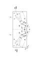
- FIG. 1 is a conceptual diagram showing a robot according to an embodiment.
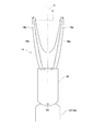
- FIG. 2 is a plan view showing the hand according to the embodiment.
- FIG. 3 is a block diagram showing a control system of the robot according to the embodiment.
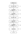
- FIG. 4 is a flowchart showing the robot position correction method according to the first embodiment.
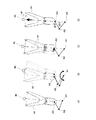
- 5A is a diagram showing a positional relationship between a hand and a target in an ideal state
- FIG. 5B is a diagram showing a facing step in the first posture
- FIGS. 5C and 5D are diagrams showing a first correction step in the first posture.
- 6A to 6D are diagrams showing the second correction step in the first posture.
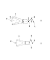
- 7A and 7B are diagrams showing the facing step to the second correcting step in the second posture.
- FIG. 8 is a diagram showing a position correction method according to the second embodiment.
- FIG. 1 shows a robot 1.
- the robot 1 can be used to transfer the substrate S in a semiconductor processing facility that manufactures semiconductor elements.
- the substrate S is a material of a semiconductor element called a wafer, and is formed in a disc shape.
- the semiconductor processing equipment is provided with a plurality of processing devices for performing various kinds of processing such as heat treatment, impurity introduction processing, thin film formation processing, lithography processing, cleaning processing, or planarization processing on the substrate S.
- the robot 1 conveys, for example, the substrate S stored in the cassette 2 to the processing device.
- the cassette 2 is, for example, a front opening type integrated pod (FOUP).
- FOUP front opening type integrated pod
- a single cassette 2 is shown, even if an EFEM (Equipment Front End Module) equipped with a plurality (for example, 2 or 3) of cassettes 2 is installed in the semiconductor processing facility, Good.
- the robot 1 is configured to be accessible in each cassette 2 without a traveling device.
- the robot 1 includes a base 10, an arm 12, a hand 14, a sensor 17, and a control device 20.
- the base 10 is fixed to an appropriate place of the semiconductor processing facility (for example, a horizontal floor surface) (or may be supported on the facility floor surface via a traveling device).
- the directions will be described assuming that the base 10 is properly installed on a horizontal floor surface.
- the arm 12 is connected to the base 10 via a lifting shaft 11.
- the elevating shaft 11 can move in the vertical direction (Z direction) with respect to the base 10, thereby moving the arm 12 and the hand 14 in the vertical direction.
- the arm 12 is configured by connecting two or more links.
- the hand 14 is connected to the arm 12.
- the robot 1 or the arm 12 is a so-called horizontal articulated type. In the robot 1, a plurality of rotation axes A1, A2... Are set so as to be parallel to each other at each of the plurality of connecting portions. All the rotation axes A1, A2... Are oriented in the vertical direction (Z direction).
- the “plurality of connecting portions” includes a connecting portion between the base 10 and the arm 12, a connecting portion between two adjacent links of the links forming the arm 12, and a connecting portion between the arm 12 and the hand 14. Be done.
- the number of rotating shafts in the robot 1 corresponds to the number of connecting portions provided from the base 10 to the hand 14.
- the arm 12 has two links, that is, the first link 13a and the second link 13b, and the robot 1 is set with three connecting portions and three rotating shafts. (If the number of links is 3 or more, 4 or more rotation axes will be set in the robot 1.)
- the base end of the first link 13a is connected to the base 10 so as to be rotatable around the rotation axis A1.
- the base end of the second link 13b is connected to the tip of the first link 13a so as to be rotatable about the rotation axis A2.
- the hand 14 is rotatably connected to the tip of the second link 13b about the rotation axis A3.
- the links 13a and 13b and the hand 14 can swing in a horizontal plane (XY plane).
- the hand 14 can move along an arbitrary trajectory (including a straight line and a curved line) in a horizontal plane according to the posture of the arm 12 (rotational angles around the respective rotation axes A1 to A3).
- the three rotation axes A1 to A3 are referred to as the first axis A1, the second axis A2, and the third axis A3 in order from the one closest to the base 10.
- the rotation angle around the first axis A1 is called the first rotation angle ⁇ 1
- the rotation angle around the second axis A2 is called the second rotation angle ⁇ 2
- the rotation angle around the third axis A3 is called the third rotation angle ⁇ 3.
- the connecting portion (the connecting portion between the first link 13a and the second link 13b in the two-link type embodiment) where the central second axis A2 is set may be referred to as an "elbow joint". is there.
- the elbow joint Je projects to the first side (for example, the left side or the minus side in the X direction).
- the posture in which the elbow joint extends from the top to the second side (for example, the right side or the plus side in the X direction) opposite to the first side when viewed from above is temporarily referred to as the “second posture”.
- the first rotation angle ⁇ 1 has a positive value in the first posture
- the first rotation angle ⁇ 1 has a negative value in the second posture.
- FIG. 2 shows the hand 14.
- the hand 14 has a thin plate shape.
- the hand 14 extends horizontally from the tip of the arm 12.
- the hand 14 can hold the disk-shaped substrate S on its upper surface, so that the substrate S is kept in a substantially horizontal posture.
- the structure for holding is not particularly limited, and an edge grip type or a suction type can be adopted.
- the hand 14 is formed in a U shape when viewed from above.
- the hand 14 has a single base end portion 15, and a first tip end portion 16 a and a second tip end portion 16 b that extend in a bifurcated manner from the base end portion 15.
- the hand 14 is symmetrical with respect to the reference line C when viewed from above.
- the base end portion 15 of the hand 14 is connected to the arm 12 such that the rotation axis A3 is located on the reference line C.
- the sensor 17 forms the detection light L propagating in the space between the first tip portion 16a and the second tip portion 16b of the hand 14.
- the detection light L has a beam shape.
- the sensor 17 detects whether or not an object blocks the detection light L, in other words, whether or not the object exists in the space.
- the sensor 17 is of a transmissive type in the present embodiment, it may be of a reflective type.
- the sensor 17 has a light emitting element 18a and a light receiving element 18b.
- the light emitting element 18a is driven by the control device 20 to generate detection light L, and the detection light L is guided to the first tip 16a via the optical fiber 19a and emitted from the first tip 16a to the space.
- the detection light L travels linearly in the space, enters the second tip portion 16b, and is guided to the light receiving element 18b via the optical fiber 19b.
- the light receiving element 18b outputs a signal according to the amount of received light to the control device 20.
- the characteristics of the signal output from the sensor 17 change depending on whether or not the object blocks the detection light L.
- the control device 20 can determine whether or not the detection light L is blocked based on the difference in the signal characteristics.
- FIG. 3 shows the control system of the robot 1.
- the controller 20 controls the operation of the arm 12 and the hand 14.
- the control device 20 is, for example, a robot controller including a computer such as a micro controller, and is not limited to a single device and may be composed of a plurality of devices.
- the control device 20 includes a calculation unit 21, a storage unit 22, and a servo control unit 23.
- the storage unit 22 stores information such as the basic program of the control device 20 and the operation program of the robot 1.
- This operation program includes not only a work program for the robot 1 to be put into practical use in a semiconductor processing facility to automatically carry out a work for transferring a substrate S, but also a machining error, an assembly error and/or an installation of the robot 1 before the work It also includes a program for correcting a positional deviation caused by an error such as an error.
- the "positional deviation” means the position, orientation or coordinates (hereinafter, may be referred to as software value) of the arm 12 or hand 14 recognized by the control device 20 and the actual arm 12 or hand caused by an error.
- the position correction method according to the embodiment is executed by executing the program for this correction.
- the storage unit 22 can also temporarily store data acquired during the execution of the program.
- the arithmetic unit 21 executes arithmetic processing for robot control and generates control commands for the robot 1.
- the servo control unit 23 is configured to control the drive device 26 of the robot 1 based on the control command generated by the calculation unit 21.
- the drive device 26 includes, for example, a lift actuator 27a (for example, a ball screw) for moving the lift shaft 11 up and down, and a plurality of rotary actuators 28a, 28b, 28c (for example, electric motors) corresponding to the rotary shafts A1 to A3, respectively. included.
- the drive device 26 moves the hand 14 in accordance with a control command from the control device 20. In the following description, changes in the postures or positions of the arm 12 and the hand 14 are realized through the control executed by the control device 20.
- the target 40 is installed within the movable range of the robot 1 (at a position where the hand 14 is accessible).
- the target 40 may be removably installed by a worker in the semiconductor processing facility, or may be installed in advance inside or on the outer surface of the cassette 2.
- the shape and posture of the target 40 during installation are arbitrary.
- the target 40 may be formed in a cylindrical shape and may be called a “pin”.
- the horizontal cross section of the target 40 is a circle.
- only a part of the horizontal cross section of the target 40 may be an arc.
- the target 40 is installed in a posture that extends in the vertical direction.
- the center line C (or simply the center line C) of the hand 14 is assumed to be a line that passes through the third axis A3 and is perpendicular to the detection light L.
- the center of the target 40 is the center of the circle or arc of the horizontal cross section of the target 40.
- the hand 14 is opposed to the target 40 with the arm 12 in the first initial posture (S1).
- the postures of the arm 12 and the hand 14 are set such that the center of the target 40 and the first axis A1 are located on the center line C when viewed from above, assuming that there is no error.
- the control device 20 controls the drive device so that the postures of the arm 12 and the hand 14 are in the first initial posture shown in FIG. 5A.
- FIG. 5A shows an ideal positional relationship that the control device 20 is trying to realize by executing this step. However, actually, due to the accumulated error, even if the arm 12 and the hand 14 are set to the first initial posture, the center of the target 40 deviates from the center line C as shown in FIG. 5B.
- the correction necessary to correct this deviation and position the center of the target 40 on the center line C is performed (S2).
- the technique taught in Patent Document 1 described above can be preferably applied, and the technique taught in the document is incorporated herein.
- the hand 14 is swung around the third axis A3 in a state where the rotation axes of the first axis A1 and the second axis A2 are not operated.
- the rotation angle of the third axis A3 at the time of blocking is acquired.
- the control device 20 moves the hand 14 based on the determined degree of deviation, thereby positioning the center of the target 40 on the center line C when viewed from above. (See Figure 5D).
- the first axis A1 may not be located on the center line C when viewed from above. Therefore, next, the second correction step S3 is executed.
- the arm 12 and the hand 14 are swung around the first axis A1 in a state where the rotation axes of the second axis A2 and the third axis A3 are not operated. Then, the rotation angle of the first axis A1 when the target 40 blocks the detection light L by rotating clockwise, and the first axis A1 when the target 40 blocks the detection light L by rotating counterclockwise. Gets the rotation angle of. Based on the acquired rotation angle, the first axis, the second axis, and the third axis are rotated so as to rotate the hand 14 around the center of the target 40.
- the rotational movement amount around the center of the target 40 is determined according to the acquired rotation angle of the first axis A1, and when viewed from above, the center line C of the hand 14 is defined by the first axis A1 and the target 40. It is the amount of rotational movement required to overlap with the straight line connecting the center.
- the hand 14 is linearly moved along the center line C toward the target 40.
- the target 40 is moved in a straight line until it blocks the detection light L, and the hand 14 is moved back in a straight line for a predetermined distance Ld.
- Ld may be 0.
- the distance between the center of the target 40 and the center line C and the first axis A1 and the center line C This includes that the distance from C is equal to or less than a predetermined allowable value other than 0.
- the predetermined allowable value is set to a value that is small enough to allow the robot 1 to transfer the substrate S.
- the hand 14 is made to face the target 40 with the arm 12 in the second initial posture (S4).
- the series of processes that have been advanced after the first initial posture is performed are similarly executed (S5, S6).
- the rotation angle of the second axis A2 and the rotation angle of the third axis A3 are stored in the second correction step.
- the absolute values of the second rotation angle acquired in the first posture and the second rotation angle acquired in the second posture are equal to each other, and the first rotation angle is equal to the first rotation angle.
- the absolute values of the third rotation angle acquired in the posture and the third rotation angle acquired in the second posture are equal to each other. If the absolute values are not equal in this way, it means that there is a deviation between the position recognized by the control device 20 and the actual position. Therefore, the angle value required to make these absolute values equal is calculated (S7).
- This angle value is a correction amount for correcting the deviation of the rotation angle around the second axis A2, and is a correction amount for correcting the deviation of the rotation angle around the third axis A3.
- the initial position can be corrected (zeroing correction), and the teaching position specified by the work program can be corrected (teaching position correction).
- the drive unit 26 By driving the drive unit 26 so that the arm is in the first initial posture by adding the correction amount to the software value that originally defines the first initial posture, the center of the target 40 and the first The one axis A1 is located on the center line C, and the hand 14 can be located at a position separated from the target by an estimated distance.
- the rotation angle of the first axis can also be corrected.
- the two targets will be referred to as a first target 40a and a second target 40b.
- the two targets 40a and 40b are installed so that the distance from the first axis A1 to the first target 40a is equal to the distance from the first axis A1 to the second target 40b. ..
- the first target 40a is installed in one cassette 2 and the second target 40b is installed in another cassette 2.
- the two distances are not always equal. Since the correction about the second axis A2 and the third axis A3 is performed through the first correction step, the second correction step and the correction amount calculation step described above, here, by correcting the software value about the first axis A1.
- the final position correction is performed.
- the facing step in the first posture to the second correcting step described above is performed using the first target 40a
- the facing step in the second posture to the second correcting step is performed using the target 40b. Execute. Then, in the first posture, the distance B from the first axis to the first target and the rotation angle ⁇ 1 of the first axis are acquired. Further, the distance B′ from the first axis to the second target and the rotation angle ⁇ 1′ of the first axis in the second posture are acquired.
- the two distances obtained are equal to each other, and the first distance obtained in the first attitude is equal to each other.
- One rotation angle becomes equal to the second rotation angle acquired in the second posture. If they are different, it means that there is an error in the two distances and/or the attachment of the actuator 28a around the first rotation axis. Therefore, when the distances are different, a correction amount for correcting the distance is calculated. If there is a difference in the absolute value of the first rotation angle, a correction amount for eliminating the difference is calculated.
- the process proceeds to the correction amount calculation step and the second rotation angle and the third rotation angle.
- a correction amount relating to the rotation angle is calculated.
- a series of steps from the facing step in the second posture to the second correction step is omitted. Therefore, in the correction amount calculation step, the correction amount is calculated based on the parameters different from those in the first embodiment, specifically, the design parameters of the arm and the sensor 17. Since it is a design parameter, it is stored in the storage unit in advance, and the data in the storage unit is referred to in the calculation.
- the distance to the axis (the length of the second link) is the shortest distance from the third axis to the detection light L.
- the same can be applied to an arm having three or more links.
- the 3-link type there are four rotation axes.
- the three rotation axes from the side of the hand 14 are the third axis, the second axis, and the first axis, and rotation at the connecting portion between the base 10 and the arm 12 is performed. Leave the axis inactive. Thereby, the rotation angles of the first to third axes defined here can be corrected.
- the three rotary shafts are sequentially set as the first shaft, the second shaft, and the third shaft from the base 10 side, and the rotary shaft at the connecting portion between the hand 14 and the arm 12 is not operated. Accordingly, even in a robot having four or more rotation axes, the correction accuracy can be improved and the position control accuracy can be improved.
Landscapes
- Engineering & Computer Science (AREA)
- Robotics (AREA)
- Mechanical Engineering (AREA)
- Health & Medical Sciences (AREA)
- General Health & Medical Sciences (AREA)
- Orthopedic Medicine & Surgery (AREA)
- Manipulator (AREA)
- Container, Conveyance, Adherence, Positioning, Of Wafer (AREA)
Abstract
Description
Claims (5)
- ロボットの位置補正方法であって、
前記ロボットが、
基台と、
2以上のリンクを連結することで構成され、前記基台に連結されるアームと、
前記アームに連結され、二股に分かれた第1先端部および第2先端部を有するハンドと、
検出光が前記第1先端部と前記第2先端部との間で伝播するよう構成され、ターゲットが当該検出光を遮ったか否かを検出するセンサと、
前記アームおよび前記ハンドの動作を制御する制御装置と、を備え、
複数の回転軸が複数の連結部それぞれにおいて互いに平行に向くよう設定され、当該複数の連結部には、前記基台と前記アームとの連結部、前記アームを成すリンクのうち隣接2リンクの連結部、および、前記アームと前記ハンドとの連結部が含まれ、
前記回転軸のうち3つについて、前記基台に近いものから順に第1軸、第2軸および第3軸とした場合に、前記方法は、
前記第2軸が第1側に張り出した第1姿勢となるよう前記アームを駆動し、前記ハンドが予め定められた初期姿勢となるよう前記ハンドを移動させることにより、前記ハンドを前記ターゲットと対向させるステップと、
前記ハンドを前記第3軸周りに回転させ、前記ターゲットが前記検出光を遮ったときの前記第3軸周りの回転角を検出し、その検出結果に基づいて前記第3軸の位置を補正する、第1補正ステップと、
前記アームを前記第1軸周りに回転させ、前記ターゲットが前記検出光を遮ったときの前記第1軸周りの回転角を検出し、その検出結果に基づいて前記第1軸、前記第2軸および/または前記第3軸周りに前記アームおよび/または前記ハンドを回転させることで、前記第1軸と前記第3軸と前記ターゲットを同一直線上に位置付ける、第2補正ステップと、
前記第1姿勢にて前記第2補正ステップ後に取得される前記各回転軸の回転角に基づいて、前記第2軸および前記第3軸の回転角補正量を求める補正量演算ステップと、を備える、位置補正方法。 - 前記補正量演算ステップの前に、前記第2軸が前記第1側とは反対側に張り出した第2姿勢となるよう前記アームを駆動し、前記第1および第2補正ステップを実行する、繰返しステップを更に備え、
前記補正量演算ステップにおいて、前記第2軸および前記第3軸の回転角補正量が、前記第1姿勢にて前記第2校正ステップ後に取得される前記各回転軸の回転角と、前記第2姿勢にて前記第2校正ステップ後に取得される前記各回転軸の回転角とに基づいて求められる、
請求項1に記載の位置補正方法。 - 前記ターゲットが、第1ターゲットおよび第2ターゲットを含み、
前記第1姿勢での前記第1および第2補正ステップが、前記第1ターゲットを用いて実行され、前記第2姿勢での前記第1および第2補正ステップが、前記第2ターゲットを用いて実行され、
前記補正量演算ステップにおいて、前記第1軸の回転角補正量が求められる、
請求項2に記載の位置補正方法。 - 前記補正量演算ステップにおいて、前記第2軸および前記第3軸の回転角補正量が、前記第1姿勢にて前記第2校正ステップ後に取得される前記各回転軸の回転角と併せ、前記アームおよび前記センサの設計パラメータとにも基づいて、求められる、
請求項1に記載の位置補正方法。 - 基台と、
2以上のリンクを連結することで構成され、前記基台に連結されるアームと、
前記アームに連結され、二股に分かれた第1先端部および第2先端部を有するハンドと、
検出光が前記第1先端部と前記第2先端部との間で伝播するよう構成され、ターゲットが当該検出光を遮ったか否かを検出するセンサと、
前記アームおよび前記ハンドの動作を制御する制御装置と、を備え、
複数の回転軸が複数の連結部それぞれにおいて互いに平行に向くよう設定され、当該複数の連結部には、前記基台と前記アームとの連結部、前記アームを成すリンクのうち隣接2リンクの連結部、および、前記アームと前記ハンドとの連結部が含まれ、
前記回転軸のうち3つについて、前記基台に近いものから順に第1軸、第2軸および第3軸とした場合に、前記制御装置は、
前記第2軸が第1側に張り出した第1姿勢となるよう前記アームを駆動し、前記ハンドが予め定められた初期姿勢となるように移動させることにより、前記ハンドを前記ターゲットと対向させ、
前記ハンドを前記第3軸周りに回転させ、前記ターゲットが前記検出光を遮ったときの前記第3軸周りの回転角を検出し、その検出結果に基づいて前記第3軸の位置を補正し、
前記アームを前記第1軸周りに回転させ、前記ターゲットが前記検出光を遮ったときの前記第1軸周りの回転角を検出し、その検出結果に基づいて前記第1軸、前記第2軸および/または前記第3軸周りに前記アームおよび/または前記ハンドを回転させることで、前記第1軸と前記第3軸と前記ターゲットを同一直線上に位置付け、
前記第1姿勢において前記第2校正ステップ後に取得される前記各回転軸の回転角に基づいて、前記第2軸および前記第3軸の回転角補正量を求める、
ように構成されている、ロボット。
Priority Applications (3)
| Application Number | Priority Date | Filing Date | Title |
|---|---|---|---|
| KR1020217021304A KR102588876B1 (ko) | 2018-12-27 | 2019-12-19 | 로봇의 위치 보정 방법 및 로봇 |
| CN201980086637.8A CN113226664B (zh) | 2018-12-27 | 2019-12-19 | 机器人的位置修正方法以及机器人 |
| JP2020563165A JP7064623B2 (ja) | 2018-12-27 | 2019-12-19 | ロボットの位置補正方法およびロボット |
Applications Claiming Priority (2)
| Application Number | Priority Date | Filing Date | Title |
|---|---|---|---|
| US16/234,339 US10974388B2 (en) | 2018-12-27 | 2018-12-27 | Method of correcting position of robot and robot |
| US16/234,339 | 2018-12-27 |
Publications (1)
| Publication Number | Publication Date |
|---|---|
| WO2020137799A1 true WO2020137799A1 (ja) | 2020-07-02 |
Family
ID=71121640
Family Applications (1)
| Application Number | Title | Priority Date | Filing Date |
|---|---|---|---|
| PCT/JP2019/049822 Ceased WO2020137799A1 (ja) | 2018-12-27 | 2019-12-19 | ロボットの位置補正方法およびロボット |
Country Status (6)
| Country | Link |
|---|---|
| US (1) | US10974388B2 (ja) |
| JP (1) | JP7064623B2 (ja) |
| KR (1) | KR102588876B1 (ja) |
| CN (1) | CN113226664B (ja) |
| TW (1) | TWI748312B (ja) |
| WO (1) | WO2020137799A1 (ja) |
Cited By (2)
| Publication number | Priority date | Publication date | Assignee | Title |
|---|---|---|---|---|
| WO2024075839A1 (ja) * | 2022-10-07 | 2024-04-11 | 川崎重工業株式会社 | 基板搬送用ロボットシステム、および、基板搬送用ロボットによる基板の置き位置および取り位置の少なくともいずれかの補正方法 |
| WO2024190913A1 (ja) * | 2023-03-16 | 2024-09-19 | 川崎重工業株式会社 | 基板搬送用ロボットシステム、および、基板搬送方法 |
Families Citing this family (3)
| Publication number | Priority date | Publication date | Assignee | Title |
|---|---|---|---|---|
| JP6924112B2 (ja) * | 2017-09-29 | 2021-08-25 | 川崎重工業株式会社 | 基板搬送装置及び基板搬送ロボットと基板載置部との位置関係を求める方法 |
| US11673275B2 (en) | 2019-02-08 | 2023-06-13 | Yaskawa America, Inc. | Through-beam auto teaching |
| JP7433180B2 (ja) * | 2020-09-23 | 2024-02-19 | 東京エレクトロン株式会社 | 搬送装置およびロボットアームのティーチング方法 |
Citations (8)
| Publication number | Priority date | Publication date | Assignee | Title |
|---|---|---|---|---|
| JP2005118951A (ja) * | 2003-10-17 | 2005-05-12 | Yaskawa Electric Corp | キャリブレーション方法 |
| JP2009506518A (ja) * | 2005-07-11 | 2009-02-12 | ブルックス オートメーション インコーポレイテッド | 自動位置合わせ基板搬送装置 |
| WO2009145082A1 (ja) * | 2008-05-27 | 2009-12-03 | ローツェ株式会社 | 搬送装置、位置教示方法及びセンサ治具 |
| JP2010284728A (ja) * | 2009-06-09 | 2010-12-24 | Kawasaki Heavy Ind Ltd | 搬送ロボット及び自動教示方法 |
| JP2011183492A (ja) * | 2010-03-05 | 2011-09-22 | Rorze Corp | 自動位置ずれ補正方法、及び自動位置教示方法。 |
| JP2013168579A (ja) * | 2012-02-16 | 2013-08-29 | Yaskawa Electric Corp | 搬送システム |
| WO2016103292A1 (ja) * | 2014-12-22 | 2016-06-30 | 川崎重工業株式会社 | ロボットシステム及びエンドエフェクタの変形検出方法 |
| WO2016178300A1 (ja) * | 2015-05-01 | 2016-11-10 | 川崎重工業株式会社 | ロボットの教示方法及びロボット |
Family Cites Families (10)
| Publication number | Priority date | Publication date | Assignee | Title |
|---|---|---|---|---|
| JPH0774964B2 (ja) * | 1987-06-25 | 1995-08-09 | 日本鋼管株式会社 | ロボットの位置決め誤差補正方法 |
| JP2000024969A (ja) * | 1998-07-13 | 2000-01-25 | Komatsu Ltd | ワーク搬送ロボットの教示装置 |
| WO2006055770A2 (en) * | 2004-11-19 | 2006-05-26 | Dynalog, Inc. | Robot cell calibration |
| JP5685875B2 (ja) * | 2010-09-28 | 2015-03-18 | シンフォニアテクノロジー株式会社 | 治具、搬送ロボット、円盤状搬送対象物アライメント方法 |
| JP5728204B2 (ja) * | 2010-11-17 | 2015-06-03 | 株式会社アルバック | 基板位置検出方法 |
| US20160243703A1 (en) * | 2015-02-19 | 2016-08-25 | Isios Gmbh | Arrangement and method for the model-based calibration of a robot in a working space |
| DE112016004725B4 (de) * | 2015-10-14 | 2021-09-16 | Kawasaki Jukogyo Kabushiki Kaisha | Verfahren zum Teach-ln eines Roboters und Roboterarmsteuervorrichtung |
| CN108496061A (zh) * | 2016-01-18 | 2018-09-04 | 株式会社尼康 | 编码器装置、驱动装置、载置台装置以及机器人装置 |
| JP6842934B2 (ja) * | 2017-01-27 | 2021-03-17 | 株式会社Screenホールディングス | 基板搬送装置、検出位置較正方法および基板処理装置 |
| US20210023713A1 (en) * | 2019-07-24 | 2021-01-28 | Abb Schweiz Ag | Method of Automated Calibration for In-Hand Object Location System |
-
2018
- 2018-12-27 US US16/234,339 patent/US10974388B2/en active Active
-
2019
- 2019-12-19 WO PCT/JP2019/049822 patent/WO2020137799A1/ja not_active Ceased
- 2019-12-19 CN CN201980086637.8A patent/CN113226664B/zh active Active
- 2019-12-19 KR KR1020217021304A patent/KR102588876B1/ko active Active
- 2019-12-19 JP JP2020563165A patent/JP7064623B2/ja active Active
- 2019-12-26 TW TW108147742A patent/TWI748312B/zh active
Patent Citations (8)
| Publication number | Priority date | Publication date | Assignee | Title |
|---|---|---|---|---|
| JP2005118951A (ja) * | 2003-10-17 | 2005-05-12 | Yaskawa Electric Corp | キャリブレーション方法 |
| JP2009506518A (ja) * | 2005-07-11 | 2009-02-12 | ブルックス オートメーション インコーポレイテッド | 自動位置合わせ基板搬送装置 |
| WO2009145082A1 (ja) * | 2008-05-27 | 2009-12-03 | ローツェ株式会社 | 搬送装置、位置教示方法及びセンサ治具 |
| JP2010284728A (ja) * | 2009-06-09 | 2010-12-24 | Kawasaki Heavy Ind Ltd | 搬送ロボット及び自動教示方法 |
| JP2011183492A (ja) * | 2010-03-05 | 2011-09-22 | Rorze Corp | 自動位置ずれ補正方法、及び自動位置教示方法。 |
| JP2013168579A (ja) * | 2012-02-16 | 2013-08-29 | Yaskawa Electric Corp | 搬送システム |
| WO2016103292A1 (ja) * | 2014-12-22 | 2016-06-30 | 川崎重工業株式会社 | ロボットシステム及びエンドエフェクタの変形検出方法 |
| WO2016178300A1 (ja) * | 2015-05-01 | 2016-11-10 | 川崎重工業株式会社 | ロボットの教示方法及びロボット |
Cited By (4)
| Publication number | Priority date | Publication date | Assignee | Title |
|---|---|---|---|---|
| WO2024075839A1 (ja) * | 2022-10-07 | 2024-04-11 | 川崎重工業株式会社 | 基板搬送用ロボットシステム、および、基板搬送用ロボットによる基板の置き位置および取り位置の少なくともいずれかの補正方法 |
| JP2024055616A (ja) * | 2022-10-07 | 2024-04-18 | 川崎重工業株式会社 | 基板搬送用ロボットシステム、および、基板搬送用ロボットによる基板の置き位置および取り位置の少なくともいずれかの補正方法 |
| JP7864613B2 (ja) | 2022-10-07 | 2026-05-25 | 川崎重工業株式会社 | 基板搬送用ロボットシステム、および、基板搬送用ロボットによる基板の置き位置および取り位置の少なくともいずれかの補正方法 |
| WO2024190913A1 (ja) * | 2023-03-16 | 2024-09-19 | 川崎重工業株式会社 | 基板搬送用ロボットシステム、および、基板搬送方法 |
Also Published As
| Publication number | Publication date |
|---|---|
| TWI748312B (zh) | 2021-12-01 |
| US20200206934A1 (en) | 2020-07-02 |
| KR102588876B1 (ko) | 2023-10-13 |
| JP7064623B2 (ja) | 2022-05-10 |
| CN113226664B (zh) | 2024-01-09 |
| JPWO2020137799A1 (ja) | 2021-10-07 |
| KR20210100685A (ko) | 2021-08-17 |
| CN113226664A (zh) | 2021-08-06 |
| TW202032299A (zh) | 2020-09-01 |
| US10974388B2 (en) | 2021-04-13 |
Similar Documents
| Publication | Publication Date | Title |
|---|---|---|
| JP7064623B2 (ja) | ロボットの位置補正方法およびロボット | |
| KR102379269B1 (ko) | 통합된 얼라이너를 갖는 로봇 | |
| JP7064624B2 (ja) | ロボットの位置補正方法およびロボット | |
| US9929034B2 (en) | Substrate transfer device | |
| JP6058004B2 (ja) | マルチリンケージロボットを有するシステム及びマルチリンケージロボットにおいて位置アライメント及び回転アライメントを補正するための方法 | |
| US10953539B2 (en) | Substrate transfer robot and automatic teaching method | |
| JP2019084652A (ja) | 水平多関節型ロボット及びその原点復帰方法 | |
| TW202606863A (zh) | 具有重力場感測器的晶圓搬運機器人 | |
| JP2010162611A (ja) | 相対ティーチング方法 | |
| JPWO2011001675A1 (ja) | ロボットのティーチング装置及びロボットのティーチング方法 | |
| JP2025012200A (ja) | 搬送装置およびティーチング方法 | |
| WO2019064890A1 (ja) | 基板搬送装置及び基板載置部の回転軸の探索方法 | |
| JP6281554B2 (ja) | 教示治具、ロボット、教示システムおよび教示方法 | |
| KR200436002Y1 (ko) | 이중 아암 로봇 | |
| US20240058952A1 (en) | Controller for substrate transfer robot and control method for joint motor | |
| KR20240037845A (ko) | 로봇의 제어 방법 및 제어 장치 | |
| TW202031439A (zh) | 機器人控制裝置、機器人系統及機器人控制方法 | |
| TWI790027B (zh) | 機器人以及教示方法 | |
| CN111052337B (zh) | 机器人的诊断方法 | |
| WO2017104039A1 (ja) | 教示システム、教示方法およびロボット |
Legal Events
| Date | Code | Title | Description |
|---|---|---|---|
| 121 | Ep: the epo has been informed by wipo that ep was designated in this application |
Ref document number: 19902474 Country of ref document: EP Kind code of ref document: A1 |
|
| ENP | Entry into the national phase |
Ref document number: 2020563165 Country of ref document: JP Kind code of ref document: A |
|
| NENP | Non-entry into the national phase |
Ref country code: DE |
|
| ENP | Entry into the national phase |
Ref document number: 20217021304 Country of ref document: KR Kind code of ref document: A |
|
| 122 | Ep: pct application non-entry in european phase |
Ref document number: 19902474 Country of ref document: EP Kind code of ref document: A1 |