WO2020137676A1 - プレスフィット端子 - Google Patents
プレスフィット端子 Download PDFInfo
- Publication number
- WO2020137676A1 WO2020137676A1 PCT/JP2019/049328 JP2019049328W WO2020137676A1 WO 2020137676 A1 WO2020137676 A1 WO 2020137676A1 JP 2019049328 W JP2019049328 W JP 2019049328W WO 2020137676 A1 WO2020137676 A1 WO 2020137676A1
- Authority
- WO
- WIPO (PCT)
- Prior art keywords
- side corner
- pair
- press
- radius
- curvature
- Prior art date
- Legal status (The legal status is an assumption and is not a legal conclusion. Google has not performed a legal analysis and makes no representation as to the accuracy of the status listed.)
- Ceased
Links
Images



Classifications
-
- H—ELECTRICITY
- H01—ELECTRIC ELEMENTS
- H01R—ELECTRICALLY-CONDUCTIVE CONNECTIONS; STRUCTURAL ASSOCIATIONS OF A PLURALITY OF MUTUALLY-INSULATED ELECTRICAL CONNECTING ELEMENTS; COUPLING DEVICES; CURRENT COLLECTORS
- H01R12/00—Structural associations of a plurality of mutually-insulated electrical connecting elements, specially adapted for printed circuits, e.g. printed circuit boards [PCB], flat or ribbon cables, or like generally planar structures, e.g. terminal strips, terminal blocks; Coupling devices specially adapted for printed circuits, flat or ribbon cables, or like generally planar structures; Terminals specially adapted for contact with, or insertion into, printed circuits, flat or ribbon cables, or like generally planar structures
- H01R12/50—Fixed connections
- H01R12/51—Fixed connections for rigid printed circuits or like structures
- H01R12/55—Fixed connections for rigid printed circuits or like structures characterised by the terminals
- H01R12/58—Fixed connections for rigid printed circuits or like structures characterised by the terminals terminals for insertion into holes
- H01R12/585—Terminals having a press fit or a compliant portion and a shank passing through a hole in the printed circuit board
Definitions
- the technology disclosed in this specification relates to a press-fit terminal.
- the press-fit terminal includes a pair of elastic contact portions that are spaced apart from each other. When the pair of elastic contact portions are inserted into the through hole while elastically displacing in a direction of approaching each other, the elastic contact portion is brought into contact with the conductor layer formed on the inner peripheral surface of the through hole by the elastic restoring force and is electrically connected.
- the elastic contact portion and the conductor layer provided on the inner wall of the through hole are surely brought into contact with each other.
- a large strain may occur in the terminal, which is not preferable.
- a relatively large strain tends to be generated at a portion where the pair of elastic contact portions branch.
- the technology disclosed in the present specification has been completed based on the above circumstances, and a press-fit terminal having a reduced insertion force during insertion into a through hole while maintaining connection reliability is provided.
- the purpose is to provide.
- the technique disclosed in the present specification is a press-fit terminal that is inserted in a through hole provided in a circuit board along an insertion direction, and includes a base portion that extends along the insertion direction, and a base portion that extends beyond the base portion.
- a front end portion provided in the front in the insertion direction and having a front end side corner portion, a pair of deforming portions that connect the base portion and the front end portion, and that are elastically deformed by contacting the inner wall of the through hole.
- the pair of deforming portions have a deforming portion side corner portion, and the pair of deforming portion is provided at an outer deforming portion side corner portion of the deforming portion side corner portion in a direction intersecting the insertion direction.
- the curved surface has an easily deformable portion whose radius of curvature is larger than the radius of curvature of the curved surface provided at the corner portion on the tip side.
- the radius of curvature of the curved surface provided at the tip side corner is relatively small, the cross-sectional area of the tip is relatively large. As a result, the rigidity of the tip end portion becomes relatively large, so that the contact load applied to the inner wall of the through hole by the pair of deforming portions can be maintained. As a result, it is possible to prevent the holding force of the press-fit terminal from decreasing.
- the easy-deformable portion is provided at a portion where the crossover dimension of the pair of deformable portions is maximum in a direction intersecting with the inserting direction.
- the portion of the pair of deforming portions where the crossover dimension is the maximum in the direction intersecting the insertion direction surely comes into contact with the inner wall of the through hole. Since the easily deformable portion is provided in this portion, the amount of deformation of the pair of deformable portions can be reliably reduced. Thereby, the insertion force of the press-fit terminal can be surely reduced.
- the easy-deformable portion is provided at a position rearward in the insertion direction with respect to a portion where the crossover dimension of the pair of deformable portions is maximum in a direction intersecting the insertion direction.
- An intermediate portion is provided between the tip portion and the easily deformable portion in the pair of deformable portions, and the intermediate portion has an intermediate portion side corner portion, and the intermediate portion side corner portion has The radius of curvature of the provided curved surface gently changes from the radius of curvature of the corner portion on the tip end side to the radius of curvature of the corner portion on the deforming portion side.
- FIGS. 1 to 9 A first embodiment of the technology disclosed in this specification will be described with reference to FIGS. 1 to 9.
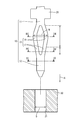
- the press-fit terminal 10 according to the present embodiment is held in a state of being inserted into the through hole 31 provided in the circuit board 30 along the insertion direction (direction indicated by arrow A).
- the lower side in FIG. 1 is the front in the insertion direction
- the upper side in FIG. 1 is the rear in the insertion direction.
- the circuit board 30 has a general structure in which conductive paths (not shown) are formed by a printed wiring technique on both front and back surfaces of an insulating plate made of an insulating material such as a glass base material and a glass nonwoven fabric base material. It is a printed circuit board having a typical structure.
- the circuit board 30 has a plurality of through holes 31. Each through hole 31 is a hole that penetrates from one surface to the other surface of the circuit board 30.
- a conductor layer (not shown) electrically connected to the conductive path is formed on the inner peripheral surface of the through hole 31 by a known method such as plating.
- the press-fit terminal 10 is formed by pressing a metal plate having excellent conductivity such as copper or copper alloy.
- the press-fit terminal 10 includes a base 11 having a substantially rectangular rod shape, a distal end 12 having a substantially rectangular rod shape located in front of the base 11 in the insertion direction, and a pair of deformable portions 13 connecting the base 11 and the distal end 12. With.
- the base portion 11 is provided with a locking portion 20 that receives a load applied from a jig or the like (not shown) when the press-fit terminal 10 is inserted into the circuit board 30 so as to project in a direction orthogonal to the insertion direction.
- Each of the pair of deforming portions 13 has a substantially thin rectangular bar shape.
- the pair of deforming portions 13 are formed so as to spread in the direction away from each other in the direction intersecting the insertion direction into the through hole 31.
- the pair of deformable portions 13 are elastically deformable in a direction toward each other.
- the maximum passing dimension W of the pair of deforming portions 13 (the dimension between the outer edges of both the deforming portions 13) in the direction intersecting the insertion direction. Is set to be larger than the diameter D of the through hole 31.
- the front end 12 of the tip portion 12 in the insertion direction (the end portion on the opposite side of the deformable portion 13) is tapered, and extends along the insertion direction.
- the tip 12 has four tip-side corners 14 extending along the insertion direction, and a curved surface is formed on the tip-side corner 14.
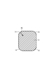
- the cross-sectional shape of the tip portion 12 is a square shape with rounded corners.
- each of the pair of deforming portions 13 has four deforming portion-side corner portions 15 extending along the insertion direction.
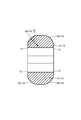
- two deforming portion side corners 15A located outside in the direction intersecting the insertion direction are formed with curved surfaces.
- the radius of curvature RL of the curved surface provided on the deforming portion side corner portion 15A is the tip. It is set to be larger than the radius of curvature RS of the curved surface provided on the side-side corner portion 14.
- the cross-sectional shape of the pair of deformable portions 13 has a rounded shape as a whole.
- a portion of the pair of deformable portions 13 where the radius of curvature RL is set to be larger than the radius of curvature RS of the tip portion 12 is defined as the easily deformable portion 16.
- the easily deformable portion 16 is formed in a region of the pair of deformable portions 13 where the transfer dimension W in the direction intersecting the insertion direction is the maximum. Furthermore, the easily deformable portion 16 is also formed in a region rearward with respect to the insertion direction, compared to a region where the crossover dimension W in the direction intersecting the insertion direction is maximum.
- each intermediate portion 17 has four intermediate-side corner portions 18 extending along the insertion direction.
- a curved surface is formed on the intermediate-side corner portion 18A of the intermediate-portion-side corner portion 18 that is outside with respect to the insertion direction and the child-traverse direction.
- the radius of curvature RM of the curved surface formed on the middle-side corner portion 18A is changed from the curvature radius RS of the curved surface provided on the tip-side corner portion 14 of the tip portion 12 to the deformable-side corner portion 15A of the easily deformable portion 16. It is set so that the radius of curvature RL of the provided curved surface changes gently.
- Step of Inserting Press-Fit Terminal 10 Next, a step of inserting the press-fit terminal 10 into the through hole 31 will be described.
- the tip portion 12 of the press-fit terminal 10 is aligned with the through hole 31, and the tip portion 12 is inserted into the through hole 31.
- the press-fit terminal 10 When the press-fit terminal 10 is further pressed forward in the insertion direction, the outer edges of the pair of deformable portions 13 are brought into sliding contact with the hole edge portions of the through holes 31. As a result, the pair of deforming portions 13 are guided into the through hole 31, and the pair of deforming portions 13 are inserted into the through hole 31 while elastically deforming so as to approach each other.
- the deformable portion 13 When the deformable portion 13 is inserted to the regular position (the position shown in FIG. 5), the portion having the largest crossover dimension W in the direction intersecting the insertion direction contacts the inner wall of the through hole 31 (inner surface of the conductor layer). .. Then, the elastic force of the pair of deforming portions 13 presses the pair of deforming portions 13 against the inner wall of the through hole 31. As a result, the press-fit terminal 10 and the conductor layer are electrically connected.
- the radius of curvature RL of the curved surface formed on the corner 15A on the deformed portion side is set to be larger than the radius of curvature RS of the curved surface formed on the corner 14 on the distal end side.
- the radius of curvature of the curved surface formed on the deformed portion side corner 15A and the radius of curvature of the curved surface formed on the tip side corner 14 are set to the same size. There is.
- the radius of curvature of the curved surface formed on the deformed portion side corner portion 15A and the tip portion side corner portion 14 of Comparative Example 1 is set to be the same as the radius of curvature of the curved surface formed on the tip portion side corner portion 14 of the first embodiment. ing.
- the radius of curvature of the curved surface formed on the deformed portion side corner portion 15A and the tip end portion side corner portion 14 of Comparative Example 2 is set to be the same as the curved surface radius formed on the deformed portion side corner portion 15A of the first embodiment. ing.
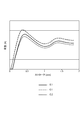
- FIG. 7 shows the relationship of the insertion load with respect to the insertion length (stroke) when the press-fit terminal 10 is inserted into the through hole 31.
- a solid line E1 shows the analysis result of Example 1
- a relatively coarse broken line C1 shows the analysis result of Comparative Example 1
- a relatively fine broken line C2 shows the analysis result of Comparative Example 2.
- the value of the insertion length is an example and is not limited to the description in this specification.
- the insertion load monotonously increases from the insertion length of 0 mm to about 0.5 mm, and monotonically decreases when the insertion length exceeds 0.5 mm. Thereby, the insertion load has a first peak in the vicinity of the insertion length of about 0.5 mm.
- the insertion load increases monotonically again, and when the insertion load exceeds 1.5 mm, it monotonically decreases. Thereby, the insertion load has a second peak in the vicinity of the insertion length of about 1.5 mm.
- the press fit terminal 10 is completely inserted into the through hole 31.
- the insertion load (insertion force) is a force that pushes the press-fit terminal 10 forward in the insertion direction against the elastic force of the pair of deformable portions 13. Therefore, the magnitude of the insertion load depends on the amount of deformation of the pair of deforming portions 13.
- the radius of curvature of the curved surface formed on the deformed portion side corner portion 15A is the same as that of the curved surface formed on the deformed portion side corner portion 15A according to the first embodiment and the comparative example 2. It is set smaller than the radius of curvature.
- the outer edges of the pair of deformable portions 13 are elastically deformed to a position separated from the inner wall of the through hole 31 in the state of being inserted into the through hole 31. That is, the elastic deformation amount of the pair of deformation portions 13 according to Comparative Example 1 is larger than the elastic deformation amount of the pair of deformation portions 13 according to Example 1 and Comparative Example 2.
- the insertion load of Comparative Example 1 is larger than that of Example 1 and Comparative Example 2.
- the insertion load of Comparative Example 2 is smaller than that of Example 1. This is because the radius of curvature of the curved surface formed on the tip side corner 14 of Comparative Example 2 is larger than the radius of curvature of the curved surface formed on the tip side corner 14 of Example 1. This is because the cross-sectional area of the tip portion 12 is smaller than the cross-sectional area of the tip portion 12 of the first embodiment.
- the holding force is reduced as described later, which is not preferable.
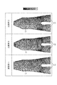
- FIG. 8 shows the strain generated at the tip portion 12 of Example 1, Comparative Example 1, and Comparative Example 2 in the state where the through-hole 31 is inserted in the regular position.
- the larger the distortion the darker the color.
- the pair of deforming portions 13 according to the comparative example 1 relatively elastically deform in a direction in which they approach each other. For this reason, in the tip portion 12 of Comparative Example 1, strain occurs such that the outer edge portions in the direction intersecting the insertion direction are pulled in mutually opposite directions with respect to the insertion direction.
- the radius of curvature RL of the curved surface formed on the deforming portion side corner portion 15A of Example 1 is set to be larger than the curvature radius of the curved surface formed on the deforming portion side corner portion 15A of Comparative Example 1,
- the deformation amount of the pair of deformation portions 13 according to No. 1 is smaller than that in Comparative Example 1.
- the radius of curvature RS of the curved surface formed on the tip side corner portion 14 of Example 1 is smaller than the curvature radius of the curved surface formed on the tip side corner portion 14 of Comparative Example 2
- the cross-sectional area of the tip portion 12 is larger than the cross-sectional area of the tip portion 12 of Comparative Example 2. As a result, the tip portion 12 of Example 1 is less likely to be distorted than the tip portion 12 of Comparative Example 2.
- FIG. 9 shows the relationship between the pullout length (stroke) and the pullout load (holding force) when the press-fit terminal 10 is pulled out from the through hole 31.
- a solid line E1 shows the analysis result of Example 1
- a relatively coarse broken line C1 shows the analysis result of Comparative Example 1
- a relatively fine broken line C2 shows the analysis result of Comparative Example 2.
- the value of the insertion/extraction length is an example and is not limited to the description in this specification.
- Drawout load is 0 when the pullout length is 0 mm.
- the withdrawal load rapidly increases and reaches the maximum value. After that, the pull-out length decreases monotonously with an increase in the pull-out length.
- the pull-out length exceeds about 1 mm, the pair of deformable portions 13 separate from the inner wall of the through hole 31, so that the pull-out load becomes zero.
- the cross-sectional area of the tip 12 of Comparative Example 1 and Example 1 is larger than the cross-sectional area of the tip 12 of Comparative Example 2. Therefore, the pull-out load of the press-fit terminal 10 according to Comparative Example 1 and Example 1 is larger than that of Comparative Example 2. As a result, in Example 1, the same level of holding force as in Comparative Example 1 can be obtained. On the other hand, in the press-fit terminal 10 according to Comparative Example 2, there is a problem that it is difficult to obtain a sufficient holding force because the cross-sectional area of the tip portion 12 is relatively small.
- the press-fit terminal 10 is the press-fit terminal 10 that is inserted into the through hole 31 provided in the circuit board 30 along the insertion direction, and includes a base portion 11 extending along the insertion direction and a base portion. 11 is provided in front of the insertion direction and has a tip end side corner portion 14 and the base portion 11 and the tip end portion 12 are coupled, and a pair of elastically deformed by contacting the inner wall of the through hole 31.
- the deformable portion 13 is provided with a deformable portion side corner portion 15 provided in the pair of deformable portion 13, and the pair of deformable portion 13 has an outer side in a direction intersecting the insertion direction among the deformable portion side corner portions 15.
- the easy-to-deform portion 16 has a radius of curvature RL of the curved surface provided at the deforming portion side corner portion 15A that is set to be larger than the curvature radius RS of the curved surface provided at the tip portion side corner portion 14.
- the radius of curvature RS of the curved surface provided on the tip side corner portion 14 is relatively small, the cross-sectional area of the tip portion 12 is relatively large. As a result, the rigidity of the tip portion 12 becomes relatively large, so that the load applied to the inner wall of the through hole 31 by the pair of deforming portions 13 can be maintained. As a result, it is possible to prevent the holding force of the press-fit terminal 10 from decreasing.
- the easily deformable portion 16 is provided at the portion where the crossover dimension W of the pair of deformable portions 13 is maximum in the direction intersecting the insertion direction.
- the portion of the pair of deformable portions 13 where the crossover dimension W is the maximum in the direction intersecting the insertion direction surely contacts the inner wall of the through hole 31. Since the easily deformable portion 16 is provided in this portion, the amount of deformation of the pair of deformable portions 13 can be reliably reduced. Thereby, the insertion force of the press-fit terminal 10 can be reliably reduced.
- the easily deformable portion 16 is provided at a position rearward with respect to the insertion direction with respect to the portion where the crossover dimension W of the pair of deformable portions 13 is maximum in the direction intersecting the insertion direction.
- the amount of deformation of the pair of deforming portions 13 is further reduced in the portion rearward in the inserting direction with respect to the portion in which the passing dimension W of the pair of deforming portions 13 is the maximum in the direction intersecting the inserting direction. Can be made. Thereby, the insertion force of the press-fit terminal 10 can be further reduced.
- the pair of deformable portions 13 is provided with the intermediate portion 17 between the tip portion 12 and the easily deformable portion 16, and the intermediate portion 17 has the intermediate portion side corner portion 18A. Therefore, the radius of curvature RM of the curved surface provided on the intermediate portion side corner portion 18A gently changes from the curvature radius RS of the tip end side corner portion 14 to the curvature radius of the deformed portion side corner portion 15A.
- the press-fit terminal 10 may have a configuration in which the intermediate portion 17 is not provided and the pair of deformable portions 13 are all the easily deformable portions 16.
- the easily deformable portion 16 may be provided in a portion different from the portion in which the passing dimension W of the pair of deformable portions 13 is maximum in the direction intersecting the insertion direction.
- the radius of curvature RM of the curved surface provided in the intermediate portion side corner portion 18 may not be gently changed from the radius of curvature of the tip end portion side corner portion 14 to the deformation portion side corner portion 15A,
- the radius of curvature RM of the curved surface provided on the middle-side corner 18 may be the same as the radius of curvature RS of the tip-side corner 14, or may be the same as the radius of curvature RL of the deformable-side corner 15A.
- the radius of curvature RM of the curved surface provided on the middle-side corner 18 may be different from the radius of curvature RS of the tip-side corner 14 and the radius of curvature RL of the deformable-side corner 15A.
Landscapes
- Coupling Device And Connection With Printed Circuit (AREA)
Abstract
回路基板30に設けられたスルーホール31に、挿入方向に沿って挿入されるプレスフィット端子10であって、挿入方向に沿って延びる基部11と、基部11よりも挿入方向の前方に設けられると共に先端部側角部14を有する先端部12と、基部11と先端部12とを連結すると共に、スルーホール31の内壁と接触して弾性変形する一対の変形部13と、を備え、一対の変形部13には変形部側角部15が設けられており、一対の変形部13は、変形部側角部15のうち挿入方向と交差する方向について外側の変形部側角部15Aに設けられた曲面の曲率半径RLが、先端部側角部14に設けられた曲面の曲率半径RSよりも大きく設定された容易変形部16を有する。
Description
本明細書に開示された技術は、プレスフィット端子に関する。
従来より、回路基板に設けられたスルーホールに圧入され、回路基板に設けられた導電回路と半田付けを行うことなく導通接続されると共に、回路基板に機械的に接触固定されるプレスフィット端子が知られている(特開2004-127610号公報参照)。プレスフィット端子は、互いに間隔を空けて配された一対の弾性接触部を備える。一対の弾性接触部を互いに接近する方向に弾性変位させつつスルーホールに挿入すると、弾性接触部が弾性復元力によってスルーホールの内周面に形成された導体層に接触し、導通接続される。
上記の構成のプレスフィット端子において、接続信頼性を確保するためには、弾性接触部と、スルーホールの内壁に設けられた導体層とを確実に接触させることが望ましい。しかし、スルーホールの内壁に対して弾性接触部から加えられる荷重を大きくしすぎると、端子に大きなひずみが生じるおそれがあるので好ましくない。特に、プレスフィット端子の挿入先端側において、一対の弾性接触部が分岐する箇所には比較的に大きなひずみが発生しやすい傾向にある。
本明細書に開示された技術は上記のような事情に基づいて完成されたものであって、接続信頼性を維持しつつ、スルーホールへの挿入時における挿入力が低減されたプレスフィット端子を提供することを目的とする。
本明細書に開示された技術は、回路基板に設けられたスルーホールに、挿入方向に沿って挿入されるプレスフィット端子であって、前記挿入方向に沿って延びる基部と、前記基部よりも前記挿入方向の前方に設けられると共に先端部側角部を有する先端部と、前記基部と前記先端部とを連結すると共に、前記スルーホールの内壁と接触して弾性変形する一対の変形部と、を備え、前記一対の変形部は変形部側角部を有し、前記一対の変形部は、前記変形部側角部のうち前記挿入方向と交差する方向において外側の変形部側角部に設けられた曲面の曲率半径が、前記先端部側角部に設けられた曲面の曲率半径よりも大きい容易変形部を有する。
上記の構成によれば、一対の変形部のうち容易変形部においては、変形部側角部に設けられた曲面の曲率半径が比較的に大きいので、スルーホールの内壁に接近しやすくなっている。これにより、一対の変形部の弾性変形量が小さくなるので、プレスフィット端子をスルーホール内に挿入する際の挿入力を低減させることができる。
また、上記の構成によれば、先端部側角部に設けられた曲面の曲率半径は比較的に小さいので、先端部の断面積は比較的に大きくなっている。これにより、先端部の剛性は比較的に大きくなるので、スルーホールの内壁に対して一対の変形部が加える接触荷重を維持することができる。この結果、プレスフィット端子の保持力が低下することを抑制することができる。
本明細書に開示された技術の実施態様としては以下の態様が好ましい。
前記挿入方向と交差する方向について前記一対の変形部の差し渡し寸法が最大となる部分に、前記容易変形部が設けられている。
上記の構成によれば、挿入方向と交差する方向について一対の変形部の差し渡し寸法が最大となる部分は、スルーホールの内壁と確実に接触するようになっている。この部分に容易変形部を設けるので、一対の変形部の変形量を確実に減少させることができる。これにより、プレスフィット端子の挿入力を確実に低減させることができる。
前記挿入方向と交差する方向について前記一対の変形部の差し渡し寸法が最大となる部分よりも前記挿入方向について後方の位置に、前記容易変形部が設けられている。
上記の構成によれば、挿入方向と交差する方向について一対の変形部の差し渡し寸法が最大となる部分よりも挿入方向について後方の部分についても、一対の変形部の変形量を更に減少させることができる。これにより、プレスフィット端子の挿入力を更に低減させることができる。
前記一対の変形部には、前記先端部と前記容易変形部との間に中間部が設けられており、前記中間部は中間部側角部を有しており、前記中間部側角部に設けられた曲面の曲率半径は、前記先端部側角部の前記曲率半径から前記変形部側角部の前記曲率半径に緩やかに変化している。
上記の構成によれば、先端部側角部から変形部側角部に至る部分には緩やかに曲率半径が変化する曲面が形成されている。これにより、スルーホールの内面が傷付くことが抑制されるので、プレスフィット端子の接続信頼性が向上する。
本明細書に開示された技術によれば、接続信頼性を維持しつつ、スルーホールへの挿入時における挿入力が低減されたプレスフィット端子を得ることができる。
<実施形態1>
本明細書に開示された技術の実施形態1を図1から図9を参照しつつ説明する。本実施形態に係るプレスフィット端子10は、回路基板30に設けられたスルーホール31に、挿入方向(矢線Aで示す方向)に沿って挿入された状態で保持されるようになっている。以下の説明において、図1における下方を挿入方向の前方とし、図1における上方を挿入方向の後方とする。
本明細書に開示された技術の実施形態1を図1から図9を参照しつつ説明する。本実施形態に係るプレスフィット端子10は、回路基板30に設けられたスルーホール31に、挿入方向(矢線Aで示す方向)に沿って挿入された状態で保持されるようになっている。以下の説明において、図1における下方を挿入方向の前方とし、図1における上方を挿入方向の後方とする。
回路基板30
図1に示すように、回路基板30は、ガラス基材、ガラス不織布基材等の絶縁材料からなる絶縁板の表裏両面に、プリント配線技術により導電路(図示せず)が形成された、一般的な構成のプリント基板である。回路基板30は複数のスルーホール31を有している。各スルーホール31は、回路基板30の一面から他面まで貫通する孔である。スルーホール31の内周面には、メッキ等の公知の手法により、導電路と電気的に接続された導体層(図示せず)が形成されている。
図1に示すように、回路基板30は、ガラス基材、ガラス不織布基材等の絶縁材料からなる絶縁板の表裏両面に、プリント配線技術により導電路(図示せず)が形成された、一般的な構成のプリント基板である。回路基板30は複数のスルーホール31を有している。各スルーホール31は、回路基板30の一面から他面まで貫通する孔である。スルーホール31の内周面には、メッキ等の公知の手法により、導電路と電気的に接続された導体層(図示せず)が形成されている。
プレスフィット端子10
図1に示すように、プレスフィット端子10は、銅、銅合金等の導電性に優れた金属板をプレス加工することによって形成される。プレスフィット端子10は、概ね角棒状の基部11と、挿入方向について基部11の前方に位置する概ね角棒状をなす先端部12と、基部11と先端部12とを連結する一対の変形部13と、を有する。基部11には、プレスフィット端子10を回路基板30へ挿入する際に図示しない治具等から印加される荷重を受ける係止部20が、挿入方向と直交する方向に突出して設けられている。
図1に示すように、プレスフィット端子10は、銅、銅合金等の導電性に優れた金属板をプレス加工することによって形成される。プレスフィット端子10は、概ね角棒状の基部11と、挿入方向について基部11の前方に位置する概ね角棒状をなす先端部12と、基部11と先端部12とを連結する一対の変形部13と、を有する。基部11には、プレスフィット端子10を回路基板30へ挿入する際に図示しない治具等から印加される荷重を受ける係止部20が、挿入方向と直交する方向に突出して設けられている。
一対の変形部13のそれぞれは、概ね細い角棒状をなしている。一対の変形部13は、スルーホール31への挿入方向と交差する方向について互いに離間する方向に広がって形成されている。
一対の変形部13は、互いに近づく方向に弾性変形可能となっている。自然状態(一対の変形部13に力が加えられていない状態)では、挿入方向と交差する方向についての、一対の変形部13の最大の差し渡し寸法W(両変形部13の外縁間の寸法)は、スルーホール31の直径Dよりも大きく設定されている。
先端部12は、挿入方向の前端(変形部13と反対側の端部)が先細りとなっており、挿入方向に沿って延びている。
図2に示すように、先端部12は、挿入方向に沿って延びる4つの先端部側角部14を有し、この先端部側角部14には曲面が形成されている。図2に示すように、先端部12の断面形状は、角が丸められた四角形状をなしている。
図3に示すように、一対の変形部13のそれぞれは、挿入方向に沿って延びる4つの変形部側角部15を有する。各変形部13に設けられた4つの変形部側角部15のうち、挿入方向と交差する方向について外側に位置する2つの変形部側角部15Aには曲面が形成されている。
図1に示すように、挿入方向について、一対の変形部13のうち後端部から約三分の二の領域においては、変形部側角部15Aに設けられた曲面の曲率半径RLが、先端部側角部14に設けられた曲面の曲率半径RSよりも、大きく設定されている。これにより、一対の変形部13の断面形状は、全体として丸みを帯びた形状をなしている。
一対の変形部13のうち曲率半径RLが、先端部12の曲率半径RSよりも大きく設定されている部分は、容易変形部16とされる。図1に示すように、容易変形部16は、一対の変形部13のうち、挿入方向と交差する方向についての差し渡し寸法Wが最大となっている領域に形成されている。更に、容易変形部16は、挿入方向と交差する方向についての差し渡し寸法Wが最大となっている領域よりも、挿入方向について後方の領域にも形成されている。
一対の変形部13のうち挿入方向についての前端部から約三分の一の領域は、中間部17とされる。図4に示すように、各中間部17は、挿入方向に沿って延びる4つの中間部側角部18を有する。中間部側角部18のうち挿入方向と子往査する方向について外側の中間部側角部18Aには曲面が形成されている。中間部側角部18Aに形成された曲面の曲率半径RMは、先端部12の先端部側角部14に設けられた曲面の曲率半径RSから、容易変形部16の変形部側角部15Aに設けられた曲面の曲率半径RLまで緩やかに変化するように設定されている。
プレスフィット端子10の挿入工程
次に、プレスフィット端子10をスルーホール31に挿入する工程について説明する。プレスフィット端子10の先端部12をスルーホール31に位置合わせし、先端部12をスルーホール31の内部に挿入する。
次に、プレスフィット端子10をスルーホール31に挿入する工程について説明する。プレスフィット端子10の先端部12をスルーホール31に位置合わせし、先端部12をスルーホール31の内部に挿入する。
更にプレスフィット端子10を挿入方向の前方に押圧すると、一対の変形部13の外縁がスルーホール31の孔縁部に摺接する。これにより、一対の変形部13がスルーホール31の内部に案内され、一対の変形部13が互いに接近するように弾性変形しつつスルーホール31内に挿入される。
変形部13が正規位置(図5に示す位置)まで挿入されると、挿入方向と交差する方向についての差し渡し寸法Wが最大となる部分がスルーホール31の内壁(導体層の内面)に接触する。すると、一対の変形部13の弾発力により、一対の変形部13がスルーホール31の内壁に押圧される。これにより、プレスフィット端子10と導体層とが電気的に接続される。
実施例及び比較例の説明
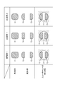
続いて、実施例及び比較例により、本明細書に開示された技術について詳細に説明する。図6を参照しつつ、実施例1、比較例1、及び比較例2に係るプレスフィット端子10について説明する。
続いて、実施例及び比較例により、本明細書に開示された技術について詳細に説明する。図6を参照しつつ、実施例1、比較例1、及び比較例2に係るプレスフィット端子10について説明する。
実施例1においては、変形部側角部15Aに形成された曲面の曲率半径RLは、先端部側角部14に形成された曲面の曲率半径RSよりも大きく設定されている。
比較例1及び比較例2においては、変形部側角部15Aに形成された曲面の曲率半径と、先端部側角部14に形成された曲面の曲率半径とは、同じ大きさに設定されている。比較例1の変形部側角部15A及び先端部側角部14に形成された曲面の曲率半径は、実施例1の先端部側角部14に形成された曲面の曲率半径と同じに設定されている。比較例2の変形部側角部15A及び先端部側角部14に形成された曲面の曲率半径は、実施例1の変形部側角部15Aに形成された曲面の曲率半径と同じに設定されている。
実施例1、比較例1、及び比較例2について、挿入力、及び保持力のCAE(Computer Aided Engineering)解析を行った。挿入力についての結果を図7に示し、保持力についての結果を図9に示す。
挿入荷重について
図7には、プレスフィット端子10をスルーホール31に挿入する際における、挿入長さ(ストローク)に対する挿入荷重の関係を示す。実線E1は実施例1の解析結果を示し、比較的に粗い破線C1は比較例1の解析結果を示し、比較的に細かな破線C2は比較例2の解析結果を示す。なお、挿入長さの値は一例であって、本明細書の記載に限定されない。
図7には、プレスフィット端子10をスルーホール31に挿入する際における、挿入長さ(ストローク)に対する挿入荷重の関係を示す。実線E1は実施例1の解析結果を示し、比較的に粗い破線C1は比較例1の解析結果を示し、比較的に細かな破線C2は比較例2の解析結果を示す。なお、挿入長さの値は一例であって、本明細書の記載に限定されない。
実施例1、比較例1、及び比較例2に共通する傾向について説明する。挿入長さが0mmから約0.5mmに至るまでは、挿入荷重は単調に増加し、挿入長さが0.5mmを超えると単調に減少する。これにより、挿入荷重は、挿入長さが概ね0.5mmの近傍で第1ピークを有する。
挿入長さが1mmから1.5mmの領域では、挿入荷重は再び単調に増加し、挿入荷重が1.5mmを超えると単調に減少する。これにより、挿入荷重は、挿入長さが概ね1.5mmの近傍で第2ピークを有する。挿入長さが1.5mmから2mmの間で、プレスフィット端子10は、スルーホール31内への挿入が完了するようになっている。
挿入荷重(挿入力)は、一対の変形部13の弾発力に抗してプレスフィット端子10を挿入方向の前方に押圧する力である。このため、挿入荷重の大小は、一対の変形部13の変形量に依存する。
図6に示すように、比較例1においては、変形部側角部15Aに形成された曲面の曲率半径は、実施例1及び比較例2に係る変形部側角部15Aに形成された曲面の曲率半径よりも小さく設定されている。これにより、一対の変形部13の外縁は、スルーホール31内に挿入された状態において、スルーホール31の内壁から離間した位置にまで弾性変形する。つまり、比較例1に係る一対の変形部13の弾性変形量は、実施例1及び比較例2に係る一対の変形部13の弾性変形量よりも大きくなっている。この結果、比較例1の挿入荷重は、実施例1及び比較例2よりも大きくなっている。
なお、比較例2の挿入荷重は、実施例1よりも小さくなっている。これは、比較例2の先端部側角部14に形成された曲面の曲率半径が、実施例1の先端部側角部14に形成された曲面の曲率半径よりも大きいため、比較例2の先端部12の断面積が実施例1の先端部12の断面積よりも小さくなっていることに起因する。比較例2の挿入荷重が実施例1よりも小さいことにより、後述するように保持力が低下してしまうので、好ましくない。
図8には、スルーホール31内の正規位置に挿入された状態における、実施例1、比較例1、及び比較例2の先端部12に生じたひずみを示す。図中、ひずみが大きい部分ほど、色が濃くなるようになっている。上記したように、比較例1に係る一対の変形部13は、互いに接近する方向について比較的に大きく弾性変形する。このため、比較例1の先端部12においては、挿入方向と交差する方向の外縁部が、挿入方向について互いに反対方向に引っ張られるようなひずみが生じる。
比較例2の変形部側角部15Aに形成された曲面の曲率半径は、比較例1の変形部側角部15Aに形成された曲面の曲率半径よりも大きく設定されているので、比較例2に係る一対の変形部13の変形量は、比較例1よりも小さい。このため、比較例2の先端部12に生じるひずみは、比較例1よりも小さくなっている。
実施例1の変形部側角部15Aに形成された曲面の曲率半径RLは、比較例1の変形部側角部15Aに形成された曲面の曲率半径よりも大きく設定されているので、実施例1に係る一対の変形部13の変形量は、比較例1よりも小さい。更に、実施例1の先端部側角部14に形成された曲面の曲率半径RSは、比較例2の先端部側角部14に形成された曲面の曲率半径よりも小さいので、実施例1の先端部12の断面積は、比較例2の先端部12の断面積よりも大きい。この結果、実施例1の先端部12は、比較例2の先端部12に比べてひずみにくくなっている。
保持力について
図9には、プレスフィット端子10をスルーホール31から引き抜く際における、引き抜き長さ(ストローク)に対する引き抜き荷重(保持力)の関係を示す。実線E1は実施例1の解析結果を示し、比較的に粗い破線C1は比較例1の解析結果を示し、比較的に細かな破線C2は比較例2の解析結果を示す。なお、挿入引き抜き長さの値は一例であって、本明細書の記載に限定されない。
図9には、プレスフィット端子10をスルーホール31から引き抜く際における、引き抜き長さ(ストローク)に対する引き抜き荷重(保持力)の関係を示す。実線E1は実施例1の解析結果を示し、比較的に粗い破線C1は比較例1の解析結果を示し、比較的に細かな破線C2は比較例2の解析結果を示す。なお、挿入引き抜き長さの値は一例であって、本明細書の記載に限定されない。
引き抜き長さが0mmにおいては、引き抜き荷重は0である。引き抜き長さが0mmを超えると引き抜き荷重は急激に上昇し、最大値となる。以後は、引き抜き長さの増大とともに単調に減少し、引き抜き長さが約1mmを超えると、スルーホール31の内壁から一対の変形部13が離間するので、引き抜き荷重は0となる。
上記したように、比較例1及び実施例1の先端部12の断面積は、比較例2の先端部12の断面積よりも大きい。このため、比較例1及び実施例1に係るプレスフィット端子10の引き抜き荷重は、比較例2に比べて大きい。これにより、実施例1は、比較例1と同程度の保持力を得ることができる。一方で、比較例2に係るプレスフィット端子10においては、先端部12の断面積が比較的に小さいために、十分な保持力を得ることが難しいという問題が生じる。
本実施形態の作用効果の説明
続いて、本実施形態の作用効果について説明する。本実施形態に係るプレスフィット端子10は、回路基板30に設けられたスルーホール31に、挿入方向に沿って挿入されるプレスフィット端子10であって、挿入方向に沿って延びる基部11と、基部11よりも挿入方向の前方に設けられると共に先端部側角部14を有する先端部12と、基部11と先端部12とを連結すると共に、スルーホール31の内壁と接触して弾性変形する一対の変形部13と、を備え、一対の変形部13には変形部側角部15が設けられており、一対の変形部13は、変形部側角部15のうち挿入方向と交差する方向について外側の変形部側角部15Aに設けられた曲面の曲率半径RLが、先端部側角部14に設けられた曲面の曲率半径RSよりも大きく設定された容易変形部16を有する。
続いて、本実施形態の作用効果について説明する。本実施形態に係るプレスフィット端子10は、回路基板30に設けられたスルーホール31に、挿入方向に沿って挿入されるプレスフィット端子10であって、挿入方向に沿って延びる基部11と、基部11よりも挿入方向の前方に設けられると共に先端部側角部14を有する先端部12と、基部11と先端部12とを連結すると共に、スルーホール31の内壁と接触して弾性変形する一対の変形部13と、を備え、一対の変形部13には変形部側角部15が設けられており、一対の変形部13は、変形部側角部15のうち挿入方向と交差する方向について外側の変形部側角部15Aに設けられた曲面の曲率半径RLが、先端部側角部14に設けられた曲面の曲率半径RSよりも大きく設定された容易変形部16を有する。
上記の構成によれば、一対の変形部13のうち容易変形部16においては、変形部側角部15Aに設けられた曲面の曲率半径RLが比較的に大きいので、スルーホール31の内壁に接近しやすくなっている。これにより、一対の変形部13の弾性変形量が小さくなるので、プレスフィット端子10をスルーホール31内に挿入する際の挿入力を低減させることができる。
また、上記の構成によれば、先端部側角部14に設けられた曲面の曲率半径RSは比較的に小さいので、先端部12の断面積は比較的に大きくなっている。これにより、先端部12の剛性は比較的に大きくなるので、スルーホール31の内壁に対して一対の変形部13が加える荷重を維持することができる。この結果、プレスフィット端子10の保持力が低下することを抑制することができる。
また、本実施形態によれば、挿入方向と交差する方向について一対の変形部13の差し渡し寸法Wが最大となる部分に、容易変形部16が設けられている。
上記の構成によれば、挿入方向と交差する方向について一対の変形部13の差し渡し寸法Wが最大となる部分は、スルーホール31の内壁と確実に接触するようになっている。この部分に容易変形部16を設けるので、一対の変形部13の変形量を確実に減少させることができる。これにより、プレスフィット端子10の挿入力を確実に低減させることができる。
また、本実施形態によれば、挿入方向と交差する方向について一対の変形部13の差し渡し寸法Wが最大となる部分よりも挿入方向について後方の位置に、容易変形部16が設けられている。
上記の構成によれば、挿入方向と交差する方向について一対の変形部13の差し渡し寸法Wが最大となる部分よりも挿入方向について後方の部分についても、一対の変形部13の変形量を更に減少させることができる。これにより、プレスフィット端子10の挿入力を更に低減させることができる。
また、本実施形態によれば、一対の変形部13には、先端部12と容易変形部16との間に中間部17が設けられており、中間部17は中間部側角部18Aを有しており、中間部側角部18Aに設けられた曲面の曲率半径RMは、先端部側角部14の曲率半径RSから変形部側角部15Aの曲率半径に緩やかに変化している。
上記の構成によれば、先端部側角部14から変形部側角部15Aに至る部分には緩やかに曲率半径RMが変化する曲面が形成されている。これにより、スルーホール31の内面が傷付くことが抑制されるので、プレスフィット端子10の接続信頼性が向上する。
<他の実施形態>
本明細書に開示された技術は上記記述及び図面によって説明した実施形態に限定されるものではなく、例えば次のような実施形態も本明細書に開示された技術の技術的範囲に含まれる。
本明細書に開示された技術は上記記述及び図面によって説明した実施形態に限定されるものではなく、例えば次のような実施形態も本明細書に開示された技術の技術的範囲に含まれる。
(1)プレスフィット端子10は、中間部17を有さず、一対の変形部13の全部が容易変形部16とされる構成であってもよい。
(2)挿入方向と交差する方向について一対の変形部13の差し渡し寸法Wが最大となる部分と異なる部分に、容易変形部16が設けられていてもよい。
(3)中間部側角部18に設けられた曲面の曲率半径RMは、先端部側角部14の曲率半径から変形部側角部15Aの曲率半径に緩やかに変化していなくてもよく、例えば、中間部側角部18に設けられた曲面の曲率半径RMは、先端部側角部14の曲率半径RSと同じでもよいし、また、変形部側角部15Aの曲率半径RLと同じでもよいし、また、中間部側角部18に設けられた曲面の曲率半径RMが、先端部側角部14の曲率半径RS及び変形部側角部15Aの曲率半径RLと異なっていてもよい。
10:プレスフィット端子
11:基部
12:先端部
13:変形部
14:先端部側角部
15,15A:変形部側角部
16:容易変形部
17:中間部
18,18A:中間部側角部
30:回路基板
31:スルーホール
A:挿入方向
W:差し渡し寸法
RL:変形部側角部に形成された曲面の曲率半径
RS:先端部側角部に設けられた曲面の曲率半径
RM:中間部側角部に設けられた曲面の曲率半径
11:基部
12:先端部
13:変形部
14:先端部側角部
15,15A:変形部側角部
16:容易変形部
17:中間部
18,18A:中間部側角部
30:回路基板
31:スルーホール
A:挿入方向
W:差し渡し寸法
RL:変形部側角部に形成された曲面の曲率半径
RS:先端部側角部に設けられた曲面の曲率半径
RM:中間部側角部に設けられた曲面の曲率半径
Claims (4)
- 回路基板に設けられたスルーホールに、挿入方向に沿って挿入されるプレスフィット端子であって、
前記挿入方向に沿って延びる基部と、
前記基部よりも前記挿入方向の前方に設けられると共に、先端部側角部を有する先端部と、
前記基部と前記先端部とを連結すると共に、前記スルーホールの内壁と接触して弾性変形する一対の変形部と、を備え、
前記一対の変形部は変形部側角部を有し、
前記一対の変形部は、前記変形部側角部のうち前記挿入方向と交差する方向において、外側の変形部側角部に設けられた曲面の曲率半径が、前記先端部側角部に設けられた曲面の曲率半径よりも大きい容易変形部を有する、プレスフィット端子。 - 前記挿入方向と交差する方向について前記一対の変形部の差し渡し寸法が最大となる部分に、前記容易変形部が設けられている、請求項1に記載のプレスフィット端子。
- 前記挿入方向と交差する方向について前記一対の変形部の差し渡し寸法が最大となる部分よりも前記挿入方向について後方の位置に、前記容易変形部が設けられている、請求項2に記載のプレスフィット端子。
- 前記一対の変形部には、前記先端部と前記容易変形部との間に中間部が設けられており、
前記中間部は中間部側角部を有しており、前記中間部側角部に設けられた曲面の曲率半径は、前記先端部側角部の前記曲率半径から前記変形部側角部の前記曲率半径に緩やかに変化している、請求項1から請求項3のいずれか一項に記載のプレスフィット端子。
Priority Applications (2)
| Application Number | Priority Date | Filing Date | Title |
|---|---|---|---|
| CN201980083451.7A CN113196575B (zh) | 2018-12-28 | 2019-12-17 | 压配合端子 |
| US17/419,184 US11705651B2 (en) | 2018-12-28 | 2019-12-17 | Press-fit terminal |
Applications Claiming Priority (2)
| Application Number | Priority Date | Filing Date | Title |
|---|---|---|---|
| JP2018-246779 | 2018-12-28 | ||
| JP2018246779A JP7205714B2 (ja) | 2018-12-28 | 2018-12-28 | プレスフィット端子 |
Publications (1)
| Publication Number | Publication Date |
|---|---|
| WO2020137676A1 true WO2020137676A1 (ja) | 2020-07-02 |
Family
ID=71129736
Family Applications (1)
| Application Number | Title | Priority Date | Filing Date |
|---|---|---|---|
| PCT/JP2019/049328 Ceased WO2020137676A1 (ja) | 2018-12-28 | 2019-12-17 | プレスフィット端子 |
Country Status (4)
| Country | Link |
|---|---|
| US (1) | US11705651B2 (ja) |
| JP (1) | JP7205714B2 (ja) |
| CN (1) | CN113196575B (ja) |
| WO (1) | WO2020137676A1 (ja) |
Cited By (1)
| Publication number | Priority date | Publication date | Assignee | Title |
|---|---|---|---|---|
| CN112004317A (zh) * | 2020-08-14 | 2020-11-27 | 苏州浪潮智能科技有限公司 | 一种pcb板及其芯片压装结构 |
Citations (2)
| Publication number | Priority date | Publication date | Assignee | Title |
|---|---|---|---|---|
| JPH05166556A (ja) * | 1991-12-16 | 1993-07-02 | Fujitsu Ltd | コンプライアントピンの構造 |
| JP2012169190A (ja) * | 2011-02-16 | 2012-09-06 | Jst Mfg Co Ltd | プレスフィット端子 |
Family Cites Families (23)
| Publication number | Priority date | Publication date | Assignee | Title |
|---|---|---|---|---|
| JP2004127610A (ja) | 2002-09-30 | 2004-04-22 | Fujitsu Ten Ltd | プレスフィット端子 |
| US7491897B2 (en) | 2002-09-30 | 2009-02-17 | Fujitsu Ten Limited | Electronic equipment provided with wiring board into which press-fit terminals are press-fitted |
| DE102004015431A1 (de) * | 2004-03-30 | 2005-10-20 | Conti Temic Microelectronic | Kontaktelement zum Einpressen in ein Loch einer Leiterplatte |
| JP2005353567A (ja) * | 2004-05-10 | 2005-12-22 | Yazaki Corp | プレスフィット端子およびそれを用いた回路基板モジュール |
| US7249981B2 (en) * | 2005-07-08 | 2007-07-31 | J.S.T. Corporation | Press-fit pin |
| US20080166928A1 (en) * | 2007-01-10 | 2008-07-10 | Liang Tang | Compliant pin |
| US8313344B2 (en) * | 2009-12-30 | 2012-11-20 | Fci Americas Technology Llc | Eye-of-the-needle mounting terminal |
| JP2013131364A (ja) * | 2011-12-21 | 2013-07-04 | Sumitomo Wiring Syst Ltd | 端子金具及び端子金具の接続構造 |
| JP6150336B2 (ja) * | 2013-08-27 | 2017-06-21 | 日本圧着端子製造株式会社 | プレスフィット端子及びこれを用いたコネクタ並びにプレスフィット端子連続体、プレスフィット端子連続体巻き付け体 |
| JP2015076317A (ja) * | 2013-10-10 | 2015-04-20 | 株式会社オートネットワーク技術研究所 | プレスフィット端子の接続構造 |
| JP6550764B2 (ja) | 2015-01-28 | 2019-07-31 | 株式会社デンソー | プレスフィット端子の製造方法および電子装置 |
| JP2016201294A (ja) * | 2015-04-13 | 2016-12-01 | 矢崎総業株式会社 | プレスフィット端子 |
| JP6447333B2 (ja) | 2015-04-14 | 2019-01-09 | 株式会社オートネットワーク技術研究所 | 基板用コネクタ |
| US9742081B1 (en) * | 2016-05-24 | 2017-08-22 | Te Connectivity Corporation | Press-fit circuit board connector |
| JP6534405B2 (ja) * | 2017-02-14 | 2019-06-26 | 矢崎総業株式会社 | プレスフィット端子 |
| CN107302146A (zh) * | 2017-07-17 | 2017-10-27 | 苏州福丰联合电子有限公司 | 导电端子 |
| CN206864682U (zh) * | 2017-07-17 | 2018-01-09 | 苏州福丰联合电子有限公司 | 导电端子 |
| JP6953919B2 (ja) * | 2017-09-04 | 2021-10-27 | 株式会社デンソー | プレスフィット端子及び電子装置 |
| CN207925708U (zh) * | 2018-03-08 | 2018-09-28 | 富士康(昆山)电脑接插件有限公司 | 电连接器端子 |
| JP6827019B2 (ja) * | 2018-07-13 | 2021-02-10 | 矢崎総業株式会社 | プレスフィット端子及び基板組立体 |
| US10868376B2 (en) * | 2018-08-28 | 2020-12-15 | Te Connectivity Corporation | Header connector including press-fit signal contacts |
| JP7084331B2 (ja) * | 2019-01-29 | 2022-06-14 | 京セラ株式会社 | プレスフィット端子 |
| US11296436B2 (en) * | 2019-06-10 | 2022-04-05 | Rohm And Haas Electronic Materials Llc | Press-fit terminal with improved whisker inhibition |
-
2018
- 2018-12-28 JP JP2018246779A patent/JP7205714B2/ja active Active
-
2019
- 2019-12-17 WO PCT/JP2019/049328 patent/WO2020137676A1/ja not_active Ceased
- 2019-12-17 US US17/419,184 patent/US11705651B2/en active Active
- 2019-12-17 CN CN201980083451.7A patent/CN113196575B/zh active Active
Patent Citations (2)
| Publication number | Priority date | Publication date | Assignee | Title |
|---|---|---|---|---|
| JPH05166556A (ja) * | 1991-12-16 | 1993-07-02 | Fujitsu Ltd | コンプライアントピンの構造 |
| JP2012169190A (ja) * | 2011-02-16 | 2012-09-06 | Jst Mfg Co Ltd | プレスフィット端子 |
Cited By (1)
| Publication number | Priority date | Publication date | Assignee | Title |
|---|---|---|---|---|
| CN112004317A (zh) * | 2020-08-14 | 2020-11-27 | 苏州浪潮智能科技有限公司 | 一种pcb板及其芯片压装结构 |
Also Published As
| Publication number | Publication date |
|---|---|
| CN113196575B (zh) | 2022-11-15 |
| US20220115795A1 (en) | 2022-04-14 |
| CN113196575A (zh) | 2021-07-30 |
| JP2020107543A (ja) | 2020-07-09 |
| US11705651B2 (en) | 2023-07-18 |
| JP7205714B2 (ja) | 2023-01-17 |
Similar Documents
| Publication | Publication Date | Title |
|---|---|---|
| JP4575494B2 (ja) | 圧入ピン | |
| US5664970A (en) | Compliant section for electrical terminal mounted to a circuit board | |
| CN109792113B (zh) | 压配合端子 | |
| JP2011090797A (ja) | プレスフィット端子、及び該プレスフィット端子を備えた電力用半導体装置 | |
| JP2005353567A (ja) | プレスフィット端子およびそれを用いた回路基板モジュール | |
| US20180123267A1 (en) | Press-fit terminal | |
| JP2007531241A (ja) | 印刷配線板の穴へ圧入するための接触子素子 | |
| JP2005235410A (ja) | 基板接続用端子 | |
| WO2020137676A1 (ja) | プレスフィット端子 | |
| CN110718780A (zh) | 压配端子和基板组件 | |
| JP2004349632A (ja) | 基板実装構造、基板実装方法および実装部品 | |
| JP2021093345A (ja) | プレスフィット端子、プレスフィット端子付基板及び機器 | |
| WO2024140652A1 (zh) | 一种外导体结构 | |
| KR20170055059A (ko) | 프레스 핏 단자 | |
| WO2021106546A1 (ja) | プレスフィット端子、プレスフィット端子付基板及び機器 | |
| KR102846827B1 (ko) | 피씨비 접속용 커넥터의 터미널 | |
| JP2018097963A (ja) | プレスフィット端子 | |
| US20240006788A1 (en) | Press-fit terminal | |
| JPH0473271B2 (ja) | ||
| CN223194046U (zh) | 一种免焊接端子 | |
| JP4503155B2 (ja) | 導電スペーサ | |
| JP2005259502A (ja) | プレスフィット端子 | |
| CN223194045U (zh) | 一种实心鱼眼端子 | |
| JPH07192822A (ja) | コネクタ | |
| JP2014013650A (ja) | コネクタ端子 |
Legal Events
| Date | Code | Title | Description |
|---|---|---|---|
| 121 | Ep: the epo has been informed by wipo that ep was designated in this application |
Ref document number: 19904519 Country of ref document: EP Kind code of ref document: A1 |
|
| NENP | Non-entry into the national phase |
Ref country code: DE |
|
| 122 | Ep: pct application non-entry in european phase |
Ref document number: 19904519 Country of ref document: EP Kind code of ref document: A1 |