WO2020137485A1 - ステンレス鋼板カーボン複合材及びその用途等 - Google Patents
ステンレス鋼板カーボン複合材及びその用途等 Download PDFInfo
- Publication number
- WO2020137485A1 WO2020137485A1 PCT/JP2019/048060 JP2019048060W WO2020137485A1 WO 2020137485 A1 WO2020137485 A1 WO 2020137485A1 JP 2019048060 W JP2019048060 W JP 2019048060W WO 2020137485 A1 WO2020137485 A1 WO 2020137485A1
- Authority
- WO
- WIPO (PCT)
- Prior art keywords
- mass
- stainless steel
- composite material
- base material
- content
- Prior art date
- Legal status (The legal status is an assumption and is not a legal conclusion. Google has not performed a legal analysis and makes no representation as to the accuracy of the status listed.)
- Ceased
Links
Images



Classifications
-
- B—PERFORMING OPERATIONS; TRANSPORTING
- B32—LAYERED PRODUCTS
- B32B—LAYERED PRODUCTS, i.e. PRODUCTS BUILT-UP OF STRATA OF FLAT OR NON-FLAT, e.g. CELLULAR OR HONEYCOMB, FORM
- B32B15/00—Layered products comprising a layer of metal
- B32B15/04—Layered products comprising a layer of metal comprising metal as the main or only constituent of a layer, which is next to another layer of the same or of a different material
- B32B15/08—Layered products comprising a layer of metal comprising metal as the main or only constituent of a layer, which is next to another layer of the same or of a different material of synthetic resin
-
- H—ELECTRICITY
- H01—ELECTRIC ELEMENTS
- H01M—PROCESSES OR MEANS, e.g. BATTERIES, FOR THE DIRECT CONVERSION OF CHEMICAL ENERGY INTO ELECTRICAL ENERGY
- H01M8/00—Fuel cells; Manufacture thereof
- H01M8/02—Details
- H01M8/0202—Collectors; Separators, e.g. bipolar separators; Interconnectors
- H01M8/0204—Non-porous and characterised by the material
- H01M8/0206—Metals or alloys
- H01M8/0208—Alloys
- H01M8/021—Alloys based on iron
-
- H—ELECTRICITY
- H01—ELECTRIC ELEMENTS
- H01M—PROCESSES OR MEANS, e.g. BATTERIES, FOR THE DIRECT CONVERSION OF CHEMICAL ENERGY INTO ELECTRICAL ENERGY
- H01M8/00—Fuel cells; Manufacture thereof
- H01M8/02—Details
- H01M8/0202—Collectors; Separators, e.g. bipolar separators; Interconnectors
- H01M8/0204—Non-porous and characterised by the material
- H01M8/0213—Gas-impermeable carbon-containing materials
-
- H—ELECTRICITY
- H01—ELECTRIC ELEMENTS
- H01M—PROCESSES OR MEANS, e.g. BATTERIES, FOR THE DIRECT CONVERSION OF CHEMICAL ENERGY INTO ELECTRICAL ENERGY
- H01M8/00—Fuel cells; Manufacture thereof
- H01M8/02—Details
- H01M8/0202—Collectors; Separators, e.g. bipolar separators; Interconnectors
- H01M8/0204—Non-porous and characterised by the material
- H01M8/0221—Organic resins; Organic polymers
-
- H—ELECTRICITY
- H01—ELECTRIC ELEMENTS
- H01M—PROCESSES OR MEANS, e.g. BATTERIES, FOR THE DIRECT CONVERSION OF CHEMICAL ENERGY INTO ELECTRICAL ENERGY
- H01M8/00—Fuel cells; Manufacture thereof
- H01M8/02—Details
- H01M8/0202—Collectors; Separators, e.g. bipolar separators; Interconnectors
- H01M8/0204—Non-porous and characterised by the material
- H01M8/0223—Composites
-
- H—ELECTRICITY
- H01—ELECTRIC ELEMENTS
- H01M—PROCESSES OR MEANS, e.g. BATTERIES, FOR THE DIRECT CONVERSION OF CHEMICAL ENERGY INTO ELECTRICAL ENERGY
- H01M8/00—Fuel cells; Manufacture thereof
- H01M8/10—Fuel cells with solid electrolytes
-
- Y—GENERAL TAGGING OF NEW TECHNOLOGICAL DEVELOPMENTS; GENERAL TAGGING OF CROSS-SECTIONAL TECHNOLOGIES SPANNING OVER SEVERAL SECTIONS OF THE IPC; TECHNICAL SUBJECTS COVERED BY FORMER USPC CROSS-REFERENCE ART COLLECTIONS [XRACs] AND DIGESTS
- Y02—TECHNOLOGIES OR APPLICATIONS FOR MITIGATION OR ADAPTATION AGAINST CLIMATE CHANGE
- Y02E—REDUCTION OF GREENHOUSE GAS [GHG] EMISSIONS, RELATED TO ENERGY GENERATION, TRANSMISSION OR DISTRIBUTION
- Y02E60/00—Enabling technologies; Technologies with a potential or indirect contribution to GHG emissions mitigation
- Y02E60/30—Hydrogen technology
- Y02E60/50—Fuel cells
-
- Y—GENERAL TAGGING OF NEW TECHNOLOGICAL DEVELOPMENTS; GENERAL TAGGING OF CROSS-SECTIONAL TECHNOLOGIES SPANNING OVER SEVERAL SECTIONS OF THE IPC; TECHNICAL SUBJECTS COVERED BY FORMER USPC CROSS-REFERENCE ART COLLECTIONS [XRACs] AND DIGESTS
- Y02—TECHNOLOGIES OR APPLICATIONS FOR MITIGATION OR ADAPTATION AGAINST CLIMATE CHANGE
- Y02P—CLIMATE CHANGE MITIGATION TECHNOLOGIES IN THE PRODUCTION OR PROCESSING OF GOODS
- Y02P70/00—Climate change mitigation technologies in the production process for final industrial or consumer products
- Y02P70/50—Manufacturing or production processes characterised by the final manufactured product
Definitions
- the present invention relates to a stainless steel sheet carbon composite material, a fuel cell separator using the composite material, a cell and a stack, an electrochemical hydrogen compressor separator and an electrochemical hydrogen compressor using the composite material, and a stainless steel sheet. ..
- FIGS. 5 and 6A and 6B an example of a fuel cell and a fuel cell separator is shown in FIGS. 5 and 6A and 6B.
- FIG. 5 is an exploded view showing a structure of a unit cell constituting the fuel cell 17
- FIG. 6 is a view showing a structure of the fuel cell separator 5 shown in FIG.
- FIG. 6A is a plan view
- FIG. 6B is a sectional view taken along line XY of FIG. 6A.
- the polymer electrolyte fuel cell 17 is a stack in which several tens to several hundreds of the unit cells 10 are stacked.
- a MEA membrane electrode electrode assembly
- a fuel gas hydrogen gas
- an oxidizing gas oxygen gas
- the fuel cell separator 5 includes a plurality of gas supply/discharge grooves 11 and a plurality of gas supply/discharge grooves 11 on one or both surfaces of a thin plate-shaped body.
- the groove 11 has an opening 12 for supplying a fuel gas or an oxidizing gas, and a fixing hole 13 for arranging the MEAs in parallel.
- the fuel cell separator 5 has a role of separating the fuel gas and the oxidizing gas flowing in the fuel cell so as not to mix with each other, transmits electric energy generated in the MEA to the outside, and heat generated in the MEA to the outside. It plays an important role of radiating heat to.
- the characteristics required for the fuel cell separator are long-term durability (corrosion resistance) under the usage environment (high temperature, corrosiveness, low pH, etc.) in the fuel cell, and electrical characteristics for reducing power generation loss. It has low resistance and excellent conductivity (high conductivity, low contact resistance), and has gas impermeability for completely separating the fuel gas and the oxidizing gas on both sides. In addition, when it is assumed to be mounted on a vehicle, it is required to have strength and flexibility that do not break even with bolt tightening and vibration during assembly.
- the workability of the base material that is, the adhesion between the base material and the carbon layer.
- the adhesion between the base material and the carbon layer is referred to as "workability of the base material” in the present application. ").
- the stainless steel sheet carbon composite materials described in Patent Documents 1 and 2 were considered to have room for further improvement in conductivity and workability. Based on such an idea of conductivity and workability (adhesion of carbon layer), a composite in which a carbon layer containing a carbonaceous material and a matrix resin is laminated on a low chromium stainless steel substrate The material was prepared and the conductivity and workability were examined. This composite material has improved conductivity and workability (adhesion to the carbon layer). However, it was surprisingly found that this composite material causes another problem that the matrix resin in the carbon layer is deteriorated and the corrosion resistance is lowered.
- the cause of deterioration of the matrix resin in the composite material of the low chromium content stainless steel as the base material and the carbon layer was further examined.
- the content of copper (Cu) in the surface layer region of the stainless steel substrate (including the oxide film layer that naturally forms on the stainless steel surface) is much higher than in other regions. It turned out to be high (thickened).
- the Cu concentrated in the surface layer causes the deterioration of the matrix resin. That is, it was found that the deterioration of the matrix resin was due to so-called copper damage (here, "concentration in the surface layer” means that the content of the surface layer is higher than other areas of the steel material). ..
- the concentration of Cu in the surface layer of such a stainless steel base material although its detailed principle is not clear, as long as it is confirmed in Examples and Comparative Examples described later, it is contained in the stainless steel base material from the beginning. It is presumed that it is caused by the content of Cu to be caused and the oxide film removal (cleaning treatment with acid) on the surface of the substrate which is carried out in the subsequent manufacturing process. Furthermore, it was surprisingly found that the content of Cu concentrated in the surface layer of the base material also contributes to the conductivity as a separator (stainless steel sheet carbon composite material). Further, not only Cu but also carbon (C) is concentrated in the surface layer of the base material, and the content of the concentrated C also contributes to the adhesion between the base material and the carbon layer. There was found.
- Patent Document 3 does not disclose that a carbon layer having a matrix resin is laminated, and no consideration is given to deterioration of the matrix resin due to concentrated Cu.
- An object of the present invention is to provide a stainless steel sheet carbon composite material having excellent conductivity, corrosion resistance, and workability (adhesion between a base material and a carbon layer). Another object of the present invention is to provide a fuel cell separator, cell, and stack using such a stainless steel plate carbon composite material. Another object of the present invention is to provide an electrochemical hydrogen compressor separator and an electrochemical hydrogen compressor using such a stainless steel plate carbon composite material. Further, another object of the present invention is to provide a stainless steel plate carbon composite material as described above and a stainless steel plate applicable to a separator, a cell, a stack and the like for fuel cells using the same.
- the gist of the present invention is as follows.
- a stainless steel plate carbon composite material in which a carbon layer containing a carbonaceous material and a matrix resin made of a thermoplastic resin or a thermosetting resin is laminated on at least one surface of a stainless steel plate-shaped substrate,
- the base material contains at least 0.001 to 0.2 mass% of carbon (C), 9.0 mass% or more and less than 16.0 mass% of chromium (Cr), and 0.005 to 1 of copper (Cu).
- the Cu content in the measurement range defined by (i) below is 0.010 to 0.30.
- a stainless steel sheet carbon composite material having a mass% and a C content of 2 to 15 mass% in a measurement range defined by (ii) below.
- the said base material is a stainless steel plate carbon composite material as described in (1) which has the following chemical compositions.
- C 0.001 to 0.2% by mass, Si: 0.01 to 2.0 mass%, Mn: 0.01 to 2.5% by mass, Al: 0.001 to 0.5 mass%, Cr: 9.0 mass% or more and less than 16.0 mass%, Cu: 0.005 to 1.0% by mass, P: 0.1 mass% or less, S: 0.01 mass% or less, Ni: 0 to 0.3 mass%, Ti: 0 to 2.0 mass%, Mo: 0 to 3.0% by mass, V: 0 to 1.0% by mass, Nb: 0 to 1.0 mass%, W: 0 to 1.0% by mass, Ta: 0 to 1.0 mass%, Sb: 0 to 1.0% by mass, Pb: 0 to 1.0% by mass, and the balance: Fe and impurities.
- a fuel cell comprising the fuel cell separator according to (3).
- a fuel cell stack including the fuel cell unit according to (4).
- a stainless steel plate At least 0.001 to 0.2 mass% of carbon (C), 9.0 mass% to less than 16.0 mass% of chromium (Cr), and 0.005 to 1.0 mass% of copper (Cu)
- the Cu content in the measurement range defined by the following (i') is 0.008 to 0.28% by mass
- the peak intensity of 1/50 of the peak intensity (maximum peak intensity) at this position P' is measured across the position P'where the peak intensity of Cu measured on the surface layer of the steel sheet is maximum.
- the present invention it is possible to provide a stainless steel sheet carbon composite material having excellent conductivity, corrosion resistance, and workability (adhesion between the base material and the carbon layer).
- the stainless steel sheet carbon composite material according to the present invention having such characteristics, is suitably used as a separator for fuel cells, cells and stacks, a separator for electrochemical hydrogen compressors and an electrochemical hydrogen compressor. obtain.
- FIG. 1 is a schematic explanatory view showing an outline of a procedure for glow discharge emission spectral analysis (GDS) in the present embodiment.
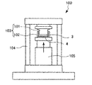
- FIG. 2 is a schematic explanatory view of a molding method for producing a carbon layer or a stainless steel plate carbon composite material.
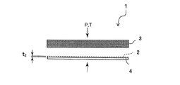
- FIG. 3 is a schematic explanatory view of a method for laminating a carbon layer, an adhesive layer, and a stainless steel plate-shaped substrate in the production of the stainless steel sheet carbon composite material of the present invention.
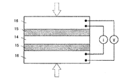
- FIG. 4 is a schematic explanatory diagram of a method for measuring contact resistance.
- FIG. 5 is an exploded view showing an example of the configuration of a unit cell that constitutes a fuel cell.
- FIG. 6(a) is a plan view showing an example of a fuel cell separator, and FIG.
- FIG. 6(b) is a sectional view showing a section taken along line XY of FIG. 6(a).
- FIG. 7 is a schematic explanatory view of another method for measuring the contact resistance.
- FIG. 8 is an exploded view showing an example of the configuration of the electrochemical hydrogen compressor.
- the stainless steel sheet carbon composite material of the present embodiment is a stainless steel plate-shaped substrate having at least one surface on which a carbon layer containing a carbonaceous material and a matrix resin made of a thermoplastic resin or a thermosetting resin is laminated.
- the plate-shaped base material contains at least a predetermined amount of carbon (C), chromium (Cr) and copper (Cu), and in the quantitative elemental analysis in the thickness direction of the base material surface layer by glow discharge emission spectroscopy, Cu And C have predetermined contents (thickened).
- ⁇ Plate-like substrate> Regarding the stainless steel plate-shaped substrate (stainless steel plate, hereinafter sometimes simply referred to as “plate-shaped substrate” or “substrate”) used in the present embodiment, at least carbon (C), There is no particular limitation as long as it contains a predetermined amount of chromium (Cr) and copper (Cu), but a material having the chemical composition described later is preferably used.
- a stainless steel sheet can be obtained by melting steel having such a chemical composition in a vacuum furnace, making an ingot, and then hot forging, hot rolling, annealing, and cold rolling. .. Known methods can be used for these processing conditions and the like.
- Examples of commercially available products include ferritic stainless steels such as SUS409, SUS405, SUS410L, and SUS429, and martensitic stainless steels such as SUS403, SUS410, and SUS420.
- ferritic stainless steels such as SUS409, SUS405, SUS410L, and SUS429
- martensitic stainless steels such as SUS403, SUS410, and SUS420.
- Such a stainless steel plate-shaped substrate can be used as an intermediate material for producing a stainless steel plate carbon composite material, or may be used alone.
- Carbon (C) is a solid solution strengthening element and contributes to improvement of the strength (for example, tensile strength) of stainless steel. Further, as described later, it is considered to be an element which is concentrated in the surface layer of the base material and contributes to the improvement of the adhesion to the carbon layer.
- the C content is less than 0.001% and is too low, it is difficult to obtain the above-described effects of strength development and concentration on the surface layer of the base material.
- the C content exceeds 0.2% and is too high, a large number of carbides are generated in the process of manufacturing the base material, and these carbides serve as starting points of fracture, which may deteriorate the formability of the stainless steel. ..
- the preferable lower limit of the C content is 0.002% by mass, and the further preferable lower limit is 0.004%.
- the preferable upper limit of the C content is 0.15%, and the further preferable upper limit is 0.1%.
- Si 0.01 to 2.0 mass% Silicon (Si) is an element effective for deoxidation. If the Si content is less than 0.01% and is too low, deoxidation may be insufficient. On the other hand, if the Si content exceeds 2.0% and is too high, the formability of stainless steel may decrease.
- the preferable lower limit of the Si content is 0.02%, and the further preferable lower limit is 0.04%.
- the preferable upper limit of Si content is 1.5%, and the further preferable upper limit is 1.0%.
- Mn 0.01 to 2.5 mass%
- Manganese (Mn) has an effect of suppressing deterioration of hot workability due to sulfur (S). Mn also has the effect of deoxidizing stainless steel. If the Mn content is less than 0.01% and too low, it is difficult to obtain these effects. On the other hand, when the Mn content exceeds 2.5% and is too high, precipitation of an intermetallic compound phase such as ⁇ phase is promoted to lower the structural stability, and the toughness and ductility of the stainless steel may be decreased. is there.
- the preferable lower limit of the Mn content is 0.02%, and the further preferable lower limit is 0.03%.
- the preferable upper limit of the Mn content is 2.0%, and the further preferable upper limit is 1.5%.
- Al 0.001 to 0.5 mass%
- Aluminum (Al) is an element effective for deoxidation. If the Al content is less than 0.001% and is too low, it is difficult to obtain the deoxidizing effect. On the other hand, if the Al content exceeds 0.5% and is too high, the cleanliness of the steel decreases, and the formability and ductility of the stainless steel decrease.
- the preferable lower limit of the Al content is 0.002%, and the further preferable lower limit is 0.005%.
- the preferable upper limit of the Al content is 0.4%, and the further preferable upper limit is 0.3%.
- Chromium (Cr) is an element effective for ensuring the corrosion resistance of stainless steel. If the Cr content is less than 9.0% and is too low, it becomes difficult to form a passivation film, and thus corrosion resistance may not be ensured. On the other hand, if the Cr content is 16.0% or more and is too high, the passivation film formed is thick, so that the conductivity of the stainless steel may be reduced. Furthermore, since such a thick passivation film has high stability, it becomes difficult to form a strong bond with another material on the outermost surface of the steel material, and workability (adhesion with the carbon layer) may be reduced. There is.
- the stainless steel having a Cr content lower than that of the conventional one is used as the base material as described above, but the corrosion resistance can be compensated by having the carbon layer described later.
- the preferable lower limit of the Cr content is 9.2%, and the further preferable lower limit is 9.5%.
- the preferable upper limit of the Cr content is 15.5%, and the further preferable upper limit is 15.0%.
- Copper (Cu) is generally an effective element for improving strength and corrosion resistance.
- the Cu content in the base material is less than 0.005% and is too low, it is difficult to obtain the above general effects, and the Cu content concentrated in the surface layer described later is There is a possibility that the effect cannot be secured, and the effect of improving conductivity cannot be obtained.
- the Cu content exceeds 1.0 mass% and is too high, the hot workability of the stainless steel may decrease, and the Cu content concentrated in the surface layer described below becomes excessive.
- the matrix resin in the carbon layer laminated on the base material may be deteriorated (damaged by copper), and the corrosion resistance may be deteriorated.
- the preferable lower limit of the Cu content is 0.006%, and the further preferable lower limit is 0.008%.
- the preferable upper limit of the Cu content is 0.95%, and the further preferable upper limit is 0.90%.
- Phosphorus (P) is an impurity. Since P segregates to the grain boundaries during solidification and embrittles the grain boundaries, its content is preferably 0.1% or less, more preferably 0.04% or less, and further preferably 0.01% or less. And the lower the better.
- S 0.01% by mass or less Sulfur (S) is an impurity. Also for S, the content thereof is preferably 0.01% or less, more preferably 0.004% or less, and further preferably 0.001%, since it segregates to the grain boundaries during solidification and embrittles the grain boundaries. Below, the lower the better.
- Ni 0 to 0.3 mass% Nickel (Ni) is not essential to be added, but since it has an effect of improving the corrosion resistance and toughness of stainless steel, it may be contained if necessary. On the other hand, if the Ni content exceeds 0.3% and is too high, a two-phase structure of ferrite and austenite is likely to be formed, and the two-phase structure has a directionality in thin plate formability, and formability as a material for fuel cell separators. May be insufficient.
- the preferable upper limit of the Ni content is 0.25%, and the further preferable upper limit is 0.2%.
- the preferable lower limit of the Ni content for obtaining the effects of the corrosion resistance and toughness is 0.001%, and the further preferable lower limit is 0.01%.
- Titanium (Ti) is not essential to be added, but is contained as necessary because it is a stabilizing element of C and N capable of reacting with C and N to form carbides and nitrides in steel. You may let me. On the other hand, if the Ti content exceeds 2.0% and is too high, the formability may be deteriorated.
- the preferable upper limit of the Ti content is 1.0%, and the further preferable upper limit is 0.5%.
- the preferable lower limit of the Ti content for obtaining the above-mentioned stabilization effect is 0.001%, and the further preferable lower limit thereof is 0.005%.
- Mo 0-3.0 mass%
- Mo molybdenum
- Mo molybdenum
- the preferable upper limit of the Mo content is 1.5%, and the further preferable upper limit is 1.0%.
- a preferable lower limit of the Mo content is 0.001%, and a further preferable lower limit thereof is 0.005% for obtaining the effect of the corrosion resistance.
- V 0 to 1.0 mass% Vanadium (V) is not essential to be added, but it is an element effective for improving the corrosion resistance of stainless steel, and may be contained if necessary. On the other hand, if the V content exceeds 1.0% and is too high, the workability may decrease.
- the preferable upper limit of the V content is 0.8%, and the further preferable upper limit is 0.5%.
- a preferable lower limit of the V content for obtaining the effect of the corrosion resistance is 0.001%, and a further preferable lower limit thereof is 0.002%.
- Niobium (Nb) is not essential to be added, but is necessary because it is a stabilizing element of C and N capable of reacting with C and N in steel to form carbides and nitrides, like Ti. You may make it contain according to it. On the other hand, if the Nb content exceeds 1.0% and is too high, the moldability may decrease. The preferable upper limit of the Nb content is 0.8%, and the further preferable upper limit is 0.5%. A preferable lower limit of the Nb content for obtaining the above-mentioned stabilizing effect is 0.0001%, and a further preferable lower limit is 0.0005%.
- W 0 to 1.0 mass% Tungsten (W) is not essential to be added, but it is an element capable of enhancing the corrosion resistance and may be contained if necessary. On the other hand, if the W content exceeds 1.0% and is too high, the moldability may decrease.
- the preferable upper limit of the W content is 0.8%, and the further preferable upper limit is 0.5%.
- a preferable lower limit of the W content is 0.001%, and a further preferable lower limit thereof is 0.002% for obtaining the effect of the corrosion resistance.
- Tantalum (Ta) is an element that does not have to be added, but is an element capable of improving the corrosion resistance, and may be contained if necessary. On the other hand, if the Ta content exceeds 1.0% and is too high, the moldability may decrease.
- the preferable upper limit of the Ta content is 0.8%, and the further preferable upper limit is 0.5%.
- a preferable lower limit of the Ta content is 0.0001%, and a further preferable lower limit thereof is 0.0002% in order to obtain the effect of the corrosion resistance.
- Sb 0 to 1.0 mass%
- antimony (Sb) is not essential to be added, it is an element capable of improving corrosion resistance, and may be contained if necessary.
- the Sb content exceeds 1.0% and is too high, the moldability may decrease.
- the preferable upper limit of the Sb content is 0.5%, and the further preferable upper limit is 0.2%.
- a preferable lower limit of the Sb content for obtaining the effect of corrosion resistance is 0.0001%, and a further preferable lower limit is 0.0002%.
- Pb 0 to 1.0 mass%
- lead (Pb) is not essential to be added, it is an element capable of improving corrosion resistance, and may be contained if necessary. On the other hand, if the Pb content exceeds 1.0% and is too high, the moldability may decrease.
- the preferable upper limit of the Pb content is 0.5%, and the further preferable upper limit is 0.2%.
- the preferable lower limit of the Pb content for obtaining the effect of the corrosion resistance is 0.0001%, and the further preferable lower limit is 0.0002%.
- the balance of the chemical composition of the base material in this embodiment is Fe and impurities.
- the impurities are those that are inevitably mixed from the ore as a raw material, scrap, or the manufacturing environment when the base material is industrially manufactured, and do not adversely affect the present embodiment. Means acceptable.
- the surface of the stainless steel plate-shaped substrate necessarily has an oxide film layer (usually about 6 nm to 25 nm) formed after removing the passivation film. It was confirmed that the contents of Cu and C elements were high in the surface layer region of the base material including the oxide film layer, although details of the morphology as a compound were not necessarily clear. That is, it was confirmed that these elements were concentrated.
- the contents of Cu and C in the surface layer of the base material are [1] for the stainless steel plate carbon composite material, a method of analyzing from the exposed base material surface after removing only the carbon layer, [2] before formation of the carbon layer
- the single stainless steel plate can be measured by a method of analyzing from the surface.
- the Cu content in the surface layer of the base material is 0.01 to 0.3 mass %. With such a Cu content, conductivity is improved (contact resistance is reduced). When the Cu content is less than 0.01% by mass, the effect of improving conductivity is poor. On the other hand, when the Cu content exceeds 0.3% by mass, particularly in the case where the base material is made of stainless steel having a low Cr content as in the present embodiment, Cu concentrated in the surface layer causes Cu in the carbon layer. Matrix resin deteriorates and corrosion resistance decreases (copper damage).
- the preferable lower limit of the Cu content is 0.05% by mass, and the preferable upper limit is 0.2% by mass.
- the stainless steel carbon composite material as a manufacturing method for controlling the Cu content of the surface layer of the base material in the above range, a base material having the above Cu content is used, and an acid cleaning treatment described below is applied to the surface layer. It suffices to reduce the elements other than Cu.
- the C content in the surface layer of the base material is 2% by mass or more and 15% by mass or less.
- workability adheresion between the base material and the carbon layer
- the C content is less than 2% by mass, the effect of improving workability is poor.
- the C content exceeds 15 mass %, the workability improving effect is saturated.
- the preferable lower limit of the C content is 3.5% by mass, and the preferable upper limit is 10% by mass.
- the carbon composite material of stainless steel plate as a manufacturing method for controlling the C content of the surface layer of the base material within the above range, it may be appropriately adjusted in the acid cleaning treatment described below without excessively increasing the cleaning time.
- the Cu and C concentrations in the surface layer of the plate-shaped substrate are measured by glow discharge emission spectroscopy (GDS).
- GDS glow discharge emission spectroscopy
- analysis is performed from the surface of the base material exposed after removing only the carbon layer.
- the C element to be measured is one in the carbon layer and one concentrated in the surface layer of the base material.
- FIG. 1A first, one carbon layer is removed (FIG. 1A), and the base material is gradually subjected to pretreatment such as cutting from the surface side where the carbon layer is removed.
- the GDS measurement is performed from the cutting surface side (that is, the center side in the thickness direction of the substrate) toward the opposite substrate surface layer side (FIG. 1B), which will be described later.
- the measurement range positions P, D1, D2 and D3
- the target element content can be measured (FIG. 1C).
- the stainless steel plate carbon composite material by performing the pretreatment and the GDS measurement from the surface side opposite to the base material surface side to be measured, the measurement error due to the peeling of the carbon layer is minimized. Can be eliminated.
- the ratio thus obtained can be used as the Cu content (mass %) of the base material surface layer in the stainless steel plate carbon composite material of the present embodiment.
- the above-mentioned position where the Cu distribution is hardly measured is defined as the position where the peak intensity of 1/50 of the peak intensity (maximum peak intensity) at the position P is measured.
- a position where Cu distribution is hardly measured on the center side in the substrate thickness direction is D1, and a position where Cu distribution is hardly measured on the opposite substrate surface side is D2, and a thickness range from D1 to D2 is set. It can be used as the “measurement range” for the Cu content.
- the measurement is performed by glow discharge emission spectroscopy (GDS) as in the case of [1].
- GDS glow discharge emission spectroscopy
- the operation of removing the carbon layer is unnecessary, and the GDS measurement is directly started from the surface (outermost surface) of the base material.
- the steps (i') and (ii') below are performed.
- (i') For Cu first, in the same manner as in the above method [1], the position (P') in the thickness direction of the substrate at which the peak intensity of Cu measured in the surface layer of the substrate becomes maximum is first grasped.
- a Cu intensity distribution is almost not measured at a position D1' [that is, a peak intensity of 1/50 of the peak intensity (maximum peak intensity) at the position P'is measured. Specified position]. Then, the ratio of the cumulative Cu content to the total element content in the thickness range (measurement range) from the surface (outermost surface) of the base material to the D1′ is the base material in the case of [2] of the present embodiment.
- the Cu content (mass %) concentrated in the surface layer can be used.
- the position P'in the thickness direction of the base material where the peak intensity of Cu is maximum is derived from the base material, as in the method of [1] above.
- the position P′ is assumed to be the position where the distribution of C is maximum, and the position where the C concentration is 1/50 of the C concentration at the position P′ on the center side in the thickness direction of the substrate (this is D3′ Is defined as the end point (A′) and the thickness range (B′) from the substrate surface (outermost surface) to the position P′ is the total thickness range for the C content.
- Measurement range Similar to the measurement of Cu element, the ratio of the integrated C content to the total element content in this measurement range is determined. The ratio thus obtained can be used as the C content (mass %) of the surface layer of the base material in the case of the base material made of a stainless steel plate.
- the Cu content is 0.008 to 0.28 mass% and the C content is 1.8 to 13.5. It was decided to set it as mass%.
- the preferable lower limit of the Cu content is 0.01% by mass, and the preferable upper limit is 0.25% by mass.
- the preferable lower limit of the C content is 3.0% by mass, and the preferable upper limit is 12% by mass.
- the stainless steel plate having the above Cu content may be subjected to an acid cleaning treatment described below to reduce the elements other than Cu in the surface layer.
- the stainless steel plate carbon composite material of the embodiment of the present invention can be manufactured.
- the contact resistance thereof is preferably 10 m ⁇ cm 2 or less, more preferably 5 m ⁇ cm 2 or less. It is more preferable that the contact resistance is 3 m ⁇ cm 2 or less, and that the contact resistance does not substantially change after 30 days.
- the thickness of the stainless steel plate-shaped substrate is not particularly limited, but is preferably 10 ⁇ m or more and 150 ⁇ m or less, more preferably 20 ⁇ m or more and 70 ⁇ m or less. If the thickness of the plate-shaped substrate is less than 10 ⁇ m, the mechanical strength may be insufficient, and if it exceeds 150 ⁇ m, problems may occur in flexibility and flexibility.
- the carbon layer laminated on the surface of the plate-shaped substrate contains a carbonaceous material and a matrix resin made of a thermoplastic resin or a thermosetting resin.
- the volume ratio (CA/R) of the carbonaceous material (CA) and the matrix resin (R) in the carbon layer is preferably 6/4 to 9/1, more preferably 7/3 to 8/2. is there.
- the thickness of the carbon layer is preferably 0.05 mm or more and 2.0 mm or less, more preferably 0.1 mm or more and 1.0 mm or less.
- the volume ratio (CA/R) of the carbonaceous material (CA) and the matrix resin (R) is smaller than 6/4, and if the ratio of the carbonaceous material is too low, the conductivity may decrease.
- the ratio of the matrix resin is too low, which may result in poor flexibility, flexibility and corrosion resistance. If the thickness of the carbon layer is less than 0.05 mm, corrosion may start from slight cracks in the carbon layer, and if it is greater than 2.0 mm, the flexibility may be poor.
- the carbonaceous material forming the carbon layer is not particularly limited as long as it has conductivity.
- the carbonaceous material for example, any one selected from natural graphite powder, artificial graphite powder, expanded graphite powder, expanded graphite powder, flake graphite powder, spherical graphite powder, and the like, or two or more kinds thereof. Can be mentioned. From the viewpoint of flexibility and conductivity, it is preferable that at least expanded graphite powder and/or expanded graphite powder be contained.
- the content of the expanded graphite powder and/or the expanded graphite powder is preferably 4% by volume or more and less than 51% by volume in the mixed powder of the carbonaceous powder and the resin powder, and 5% by volume or more and less than 21% by volume. More preferable. If it is less than 4% by volume, the flexibility may be low, while if it is 51% by volume or more, the resin that originally contributes to the adhesion between the particles or between the particles and the metal plate may function well. However, the contact resistance may increase.
- the true specific gravity of the expanded graphite powder and/or the expanded graphite powder is 2.2 g, which is the same as other graphite powders. It can be calculated as /cm 3 , and is preferably 5% by mass or more and less than 73% by mass, more preferably 7% by mass or more and less than 30% by mass.
- the particle size of the carbonaceous powder is represented by the value of D 50 (cumulative 50 volume% diameter) calculated by a particle size analyzer of a laser diffraction particle size distribution measuring device (for example, "Mastersizer 2000" manufactured by Malvern).
- the average particle size is preferably 4 ⁇ m or more and 200 ⁇ m or less, more preferably 10 ⁇ m or more and 30 ⁇ m or less. If the average particle size is less than 4 ⁇ m, the resin has a large specific surface area and is difficult to be used for bonding particles to each other or to the SUS plate, which may result in poor flexibility. If the average particle size is larger than 200 ⁇ m, it is difficult to obtain a smooth surface when forming the carbon layer, and the defect rate may increase.
- the properties of the matrix resin forming the carbon layer are not limited. It may be a thermoplastic resin or a thermosetting resin.
- the thermoplastic resin is not particularly limited and can be selected according to the application, but is preferably polypropylene resin (PP), polyethylene resin (PE), polyamide resin (PA), polyphenylene sulfide resin ( PPS), polymethylpentene resin (PMP), polyetheretherketone resin (PEEK), polyphenylene ether resin (PPE), liquid crystal polymer resin (LCP), polyamideimide resin (PAI), polysulfone resin (PSU), polyethylene terephthalate resin (PET) and polybutylene terephthalate resin (PBT), and any one kind or a mixture of two or more kinds selected from the group consisting of, and the thermosetting resin may be selected according to the application. It is possible and is not particularly limited, but preferably, one or a mixture of two or more selected from the group consisting of a phenol resin and an epoxy resin can be mentioned.
- the polyolefin resin such as PP, PE and PMP
- a modified polyolefin resin obtained by modifying a part or all of an unsaturated carboxylic acid or a derivative thereof by grafting to the polyolefin resin. ..
- By using such a modified polyolefin resin it is possible to improve the flexibility as a carbon layer or a stainless steel sheet carbon composite material including the carbon layer, and improve the adhesion to SUS and the adhesion to carbon particles. It is expected and is preferable because it lowers the contact resistance.
- the graft amount (grafting rate) of the entire modified polyolefin resin is usually preferably 0.05 to 15% by mass, more preferably 0.1 to 10% by mass, and further preferably 0.1 to 3%. It is defined as mass %.
- Specific examples of the unsaturated carboxylic acid or its derivative used for grafting on the polyolefin resin before modification include acrylic acid, methacrylic acid, maleic acid, itaconic acid, citraconic acid, mesaconic acid, maleic anhydride.
- Hymic acid anhydride 4-methylcyclohex-4-ene-1,2-dicarboxylic acid anhydride, ⁇ -ethylacrylic acid, fumaric acid, tetrahydrophthalic acid, methyltetrahydrophthalic acid, endocis-bicyclo[2,2,2] 1] hept-5-ene-2,3-dicarboxylic acid (Nadic acid [trademark]), bicyclo[2.2.2]oct-5-ene-2,3-dicarboxylic anhydride, 1,2,3 , 4,5,8,9,10-octahydronaphthalene-2,3-dicarboxylic acid anhydride, 2-octa-1,3-diketospiro[4.4]non-7-ene, bicyclo[2.2.
- Hept-5-ene-2,3-dicarboxylic acid anhydride maleopimaric acid, tetrahydrophthalic acid anhydride, x-methyl-bicyclo[2.2.1]hept-5-ene-2,3-dicarboxylic acid An anhydride, x-methyl-norbornene-5-ene-2,3-dicarboxylic acid anhydride (x represents a substitution position of a methyl group), norborn-5-ene-2,3-dicarboxylic acid anhydride, etc. Can be used. Further, acid halides, amides, imides, esters and other derivatives of the above unsaturated carboxylic acids can also be used.
- unsaturated dicarboxylic acids or acid anhydrides thereof are preferable, and maleic anhydride or hymic acid anhydride is particularly preferable.
- unsaturated carboxylic acids or their derivatives may be used alone or in combination of two or more.
- halogen group chlorine or bromine can be preferably used.
- the surface of the plate-shaped base material made of stainless steel and the carbon layer laminated on this surface may be bonded to each other via an adhesive layer of usually 0.1 ⁇ m or more and 10 ⁇ m or less. ..
- the adhesive composition for forming such an adhesive layer is not particularly limited, but is preferably a modified polyolefin resin in which a part or all of an unsaturated carboxylic acid or its derivative is grafted onto a polyolefin resin.
- an adhesive composition containing an adhesive polyolefin resin (Mitsui Chemicals, Inc., trade name: Admer), unsaturated Examples thereof include an adhesive composition containing a modified polyolefin resin graft-modified with a carboxylic acid (trade name: UNISTOL manufactured by Mitsui Chemicals, Inc.).
- An adhesive composition containing a modified polyolefin resin graft-modified with halogen can also be used, and 5 wt%-phenol resin adhesive composition (solvent: Isopropyl alcohol, phenol resin: product name: AH-1148 manufactured by Lignite Co., Ltd., epoxy resin adhesive composition (product name: YSLV-80XY manufactured by Nittetsu Chemical & Materials Co., Ltd.) and the like can also be used. If the layer thickness of this adhesive layer is less than 0.1 ⁇ m, the adhesive strength may decrease, and conversely, if it exceeds 10 ⁇ m, the conductivity of the produced stainless steel sheet carbon composite material may decrease.
- a stainless steel plate-like base material having the above-described chemical composition and Cu and C contents in the surface layer is prepared (base material preparing step), A carbon layer containing a carbonaceous material and a matrix resin made of a thermoplastic resin or a thermosetting resin is formed on at least one surface (carbon layer forming step).
- a plate-shaped material made of a stainless steel plate having a predetermined chemical composition is prepared, and then surface treatment is performed.
- a steel having a predetermined chemical composition is melted in a vacuum furnace, ingoted into an ingot, and then a plate-shaped material is obtained through steps of hot forging, hot rolling, annealing, and cold rolling.
- a known method can be used for the processing conditions and the like in each step.
- at least one surface of the plate-shaped material is subjected to a surface treatment of pickling with a surface treatment solution. Then, it is washed with pure water or the like. By this surface treatment, a plate-shaped substrate having a predetermined Cu and C content in the surface layer is obtained.
- hydrofluoric acid aqueous solution to 10% strength by weight, or hydrofluoric acid (HF) and the concentration ratio of nitric acid (HNO 3) (HF / HNO 3) is be two or more HF
- a hydrofluoric acid/nitric acid mixed aqueous solution having a concentration of 2% by mass or more can be used.
- an iron chloride-containing acid aqueous solution having an acid concentration of 25 mass% or more and an iron chloride concentration of 20 mass% or more is brought into contact with at least one surface of the plate-shaped material as a pretreatment liquid.
- a pretreatment step may be performed prior to performing the surface treatment step.
- the concentration of the hydrofluoric acid aqueous solution used as the surface treatment liquid is preferably 1% by mass or more and 10% by mass or less, more preferably 3% by mass or more and 8% by mass or less. If the hydrofluoric acid concentration of the hydrofluoric acid aqueous solution is lower than 1% by mass, the Cu and C concentrations (contents) concentrated in the surface layer of the base material may not be within the predetermined range. On the other hand, when the concentration is higher than 10% by mass, the elution of stainless steel as a raw material is large, the thickness of the oxide film formed on the surface is large, and the contact resistance may be large.
- the concentration ratio (HF/HNO 3 ) of hydrofluoric acid (HF) and nitric acid (HNO 3 ) is preferably 2 As described above, it is more preferably 2.5 or more, and the HF concentration is preferably 2% by mass or more, more preferably 3% by mass or more.
- the concentration ratio (HF/HNO 3 ) of hydrofluoric acid (HF) and nitric acid (HNO 3 ) is less than 2, the contact resistance may be higher than 10 m ⁇ cm 2 , and the HF concentration is 2 Even if it is less than mass%, the contact resistance may be higher than 10 m ⁇ cm 2 .
- the concentration of hydrofluoric acid is preferably 10% by mass or less, more preferably 8% by mass or less, as described above.
- the surface treatment liquid it is necessary to appropriately set the surface treatment time.
- a hydrofluoric acid aqueous solution concentration: 3 to 8% by mass
- the plate-shaped material is brought into contact with the surface treatment liquid at a treatment temperature of 40° C. to 60° C. for about 10 to 150 seconds. You can do it. Then, it is washed with pure water or the like.
- a pretreatment is performed in which the plate-shaped material is immersed in the pretreatment liquid and then washed with pure water or the like.
- an iron chloride-containing acid aqueous solution obtained by dissolving iron chloride such as FeCl 3 in a non-oxidizing acid aqueous solution such as hydrochloric acid or hydrofluoric acid is used.
- the acid concentration is preferably 25% by mass or more, more preferably 30% by mass or more and 40% by mass or less, though it depends on the type of acid used and the type of iron chloride.
- the iron concentration is usually preferably 20% by mass or more, more preferably 20% by mass or more and 30% by mass or less.
- the pretreatment conditions for immersing the plate-shaped material in the iron chloride-containing acid aqueous solution are usually at a temperature of 30° C. or higher and 60° C. or lower and a time of 30 seconds or longer and 3 minutes or shorter. By this pretreatment, pitting corrosion can be formed in advance on the relatively thick oxide film formed on the stainless steel surface in the annealing step, or the oxide film can be thinned, so in the subsequent surface treatment step, It becomes easy to control the structure of the oxide film.
- a carbon layer containing a carbonaceous material and a matrix resin is formed on the surface of the plate-shaped substrate.
- the method for forming the carbon layer is not particularly limited. For example, a method in which a mixture containing a carbonaceous material (such as carbonaceous powder) and a matrix resin (such as resin powder) is filled on the surface of a plate-shaped substrate and hot pressed, or a resin powder and a carbonaceous powder are mixed in a solvent A method of applying the dispersed slurry to a stainless steel surface using a doctor blade or the like, followed by hot pressing after drying can be exemplified.
- a powder mixture containing a carbonaceous powder and a resin powder is subjected to warm compression molding (hot pressing) to form a sheet-like carbon layer in advance, and the obtained carbon layer is hot-reapplied to the surface of the plate-shaped substrate again.
- hot pressing warm compression molding
- the carbon layer can be continuously formed on the surface of the base material by forming and stacking the carbon layer by this hot pressing method.
- the adhesive composition is applied to the surface of the plate-shaped base material to form an adhesive layer on the surface of the plate-shaped base material.
- the steps may be performed.
- a carbon layer is formed via this adhesive layer.
- the stainless steel sheet carbon composite material of the present embodiment obtained by the method of the present embodiment preferably has a contact resistance of 10 m ⁇ cm 2 or less, more preferably 5 m ⁇ cm 2 or less, and further preferably 3 m ⁇ cm 2 It is preferable that the contact resistance is equal to or less than the following, and the contact resistance does not substantially change even in an environment corresponding to the environment in which the fuel cell is used.
- the stainless steel sheet carbon composite material of the present embodiment is not only excellent in flexibility, flexibility, compressive strength, formability, airtightness, etc., but also excellent in both electrical conductivity (low contact resistance) and corrosion resistance. Further, it is excellent in substrate processability (adhesion between the substrate and the carbon layer).
- the stainless steel sheet carbon composite material of the present embodiment is used for fuel cell separators such as polymer electrolyte fuel cells, current collector plates for redox flow secondary batteries, gaskets and packings for petroleum refining and petrochemical plants, etc. Is preferably used in.
- fuel cell separators such as polymer electrolyte fuel cells, current collector plates for redox flow secondary batteries, gaskets and packings for petroleum refining and petrochemical plants, etc. Is preferably used in.
- fuel cell separators such as polymer electrolyte fuel cells, current collector plates for redox flow secondary batteries, gaskets and packings for petroleum refining and petrochemical plants, etc. Is preferably used in.
- fuel cell separators such as polymer electrolyte fuel cells, current collector plates for redox flow secondary batteries, gaskets and packings for petroleum refining and petrochemical plants, etc. Is preferably used in.
- two MEAs each comprising a solid polymer electrolyte
- the stainless steel sheet carbon composite material of the present embodiment can also be used as a separator of an electrochemical hydrogen compressor.
- the electrochemical hydrogen compressor and its mechanism are not particularly limited, but known configurations and methods, for example, JP 2018-189300 JP, JP 2018-95953 JP, JP 2018-165385 JP It is possible to adopt the configurations and methods described in the above.
- FIG. 8 shows an example (schematic diagram) of the configuration of the electrochemical hydrogen compressor.
- an anode provided with a catalyst layer is provided on one surface of the proton conductive electrolyte membrane 31, and a cathode provided with a catalyst layer is provided on the other surface (without distinguishing between the anode and the cathode).
- Both are denoted by reference numeral 32), and these are used as an electrolyte/electrode assembly (MEA), and the MEA is sandwiched by a separator 33 that may have a gas diffusion channel.
- the power supply plate 34 is provided on the side not in contact, and the power supply plate 34 is sandwiched by separators.
- the stainless steel sheet carbon composite material of the present embodiment contributes to the efficiency of the hydrogen generation reaction and the like due to its excellent conductivity (low contact resistance), and also has a corrosion resistant environment (wet, low pH) due to its excellent corrosion resistance.
- the stainless steel sheet (stainless steel plate-shaped substrate) and the stainless steel sheet carbon composite material of the present embodiment, their manufacturing methods, and each performance evaluation will be specifically described based on Examples and Comparative Examples. ..
- a plate material made of stainless steel was prepared as follows. That is, 150 kg of stainless steel having a chemical composition (unit: mass%, the balance being Fe and impurities) as shown in Table 1 below was melted in a vacuum melting furnace of a high frequency induction heating system to form an ingot. With respect to the obtained ingot of 150 kg, hot forging is performed at 1220° C., after cutting, hot rolling is performed at 1220° C., annealing is performed at 1180° C., cold rolling is 1080° C., and annealing is 1080 Repeated at 0° C., a 50 ⁇ m thick stainless steel foil was obtained. This was used as plate-shaped materials a to n.
- Example 1 Step of Laminating Carbon Layer Using the plate-shaped substrate according to Example 1 obtained above, an adhesive layer was formed on the surface thereof, and then a carbon layer was further laminated.
- Adhesive layer forming step A modified polyolefin resin adhesive (UNISTOL manufactured by Mitsui Chemicals, Inc.) was used as the adhesive composition for forming the adhesive layer. Then, the modified polyolefin resin adhesive is applied to the surface of the plate-shaped substrate obtained above using a table coater so that the coating thickness is 10 ⁇ m, and dried at room temperature for 10 minutes to form an adhesive layer. It was obtained as a plate-shaped substrate with an adhesive layer in Example 1.
- spherical graphite powder ITO Graphite Co., Ltd. product name: SG-BH, average particle size: 20 ⁇ m
- expanded graphite powder ITO Graphite Co., Ltd. product name: EC100, average particle size: 160 ⁇ m
- matrix resin polypropylene resin (PP) powder (trade name: Flowblen HP-8522 manufactured by Sumitomo Seika Chemicals Ltd.) was used. Then, the spherical graphite powder was mixed at 60% by volume, the expanded graphite powder at 10% by volume, and the polypropylene resin powder at 30% by volume to prepare a powder mixture. As shown in FIG.
- this powder mixture (in this case, the stainless steel plate-like base material 4 with an adhesive layer is not used) is used as a press machine (tabletop hot press MP- manufactured by Toyo Seiki Seisaku-sho, Ltd.). SCL) is evenly charged into a female mold having a volume of 50 ⁇ 50 ⁇ 20 mm, and the carbon layer 3 (thickness: 0) is hot-pressed (pressure: 2 MPa, temperature: 180° C.) as a pre-press. 0.1 mm). Next, as shown in FIGS. 2 and 3, the obtained carbon layer 3 and the stainless steel plate-shaped base material 4 with the adhesive layer prepared above are stacked, and the heating temperature is 180° C.
- Example 7 The stainless steel plate carbon composite material (double-sided composite material; Test Examples 1 to 5), single-sided composite material (Test Example 6) and plate-shaped substrate (Test Example 7) according to Example 1 obtained above are described below. As is done, the corresponding evaluation was performed.
- Test Example 1 Measurement of Cu content and C content in base material surface layer (double-sided composite material)
- a 2 cm ⁇ 2 cm test piece was cut out from the stainless steel plate carbon composite material (double-sided composite material) according to Example 1.
- the carbon layer on one surface of the test piece was completely removed by polishing with a rotary polishing machine to expose the surface of the base material.
- SAICAS Surface And Interfacial Cutting Analysis System
- the exposed surface of the base material was cut to a thickness of 5 ⁇ m.
- elemental analysis was performed by glow discharge emission spectroscopy (GDS) in the thickness direction from the cutting surface side (that is, the direction from the cutting surface side to the opposite substrate surface layer side).
- GDS glow discharge emission spectroscopy
- GD-Profiler Marcus type high frequency glow discharge emission spectrometer manufactured by Horiba Ltd. was used.
- the anode diameter (analysis area) was 4 mm in diameter.
- the RF output was 35 W
- the sputtering gas species was Ar
- the pressure was 600 Pa.
- the measurement mode was pulse sputtering mode
- the sputtering interval was 300 sec
- the measurement interval was 0.04 sec. From the elemental analysis results thus obtained, the contents (% by mass) of Cu and C in the surface layer of the base material were determined as the integral values of the following measurement ranges, respectively.
- the measurement range was sufficiently about 200 nm, the measurement range for Cu (D1 to D2) was about 10 nm, and the measurement range for C (D2 to D3) was about 50 nm.
- Cu The cutting surface side (base material) where the position P in the thickness direction of the base material at which the measured peak strength of Cu is maximum is specified, and the peak strength of 1/50 of the peak strength (maximum peak strength) at this position P is measured. The position on the center side in the thickness direction) is D1, the position where the same peak intensity as this position D1 is measured on the substrate surface side (measurement target surface side) is D2, and the thickness range from these positions D1 to D2.
- the peak intensity of C is 1/50 of the peak intensity of C at the position P on the cutting surface side (center side in the thickness direction of the base material) of this position P. Is set to D3, and the thickness range from the position D3 to the above D2. The results obtained are shown in Table 2 below.
- Test Example 2 Evaluation of corrosion resistance
- the test piece was immersed in a simulated fuel cell environment, and corrosion resistance was evaluated by the presence or absence of a precipitate in the solution.
- a 20 mm ⁇ 20 mm test piece was cut out from the obtained stainless steel plate carbon composite material (double-sided composite material) according to Example 1.
- the test piece was immersed in a sulfuric acid solution (pH 3) containing 30 ppm of chloride ion (Cl ⁇ ) at 80° C. for 240 hours, and then the presence or absence of a precipitate in the solution was confirmed and evaluated according to the following criteria.
- the results obtained are shown in Table 2 below.
- ⁇ No precipitate, but discoloration of the solution is seen
- FIG. 4 is a diagram showing a configuration of an apparatus for measuring the contact resistance of the test piece, and the contact resistance was measured using this apparatus.
- a 15 mm ⁇ 15 mm test piece 14 was cut out from the stainless steel plate carbon composite material (double-sided composite material) according to Example 1.
- This test piece was sandwiched by a pair of carbon paper 15 [TGP-H-90 manufactured by Toray Industries, Inc.] used as a gas diffusion layer for a fuel cell, and sandwiched by a pair of gold-plated platinum electrodes 16. It is.
- the area of each carbon paper 15 was 1 cm 2 .
- Test Example 4 Evaluation of adhesion between base material and carbon layer
- a test piece of 50 mm ⁇ 50 mm was cut out within 24 hours from its production.
- the adhesion strength of this test piece was evaluated using the cross-cut method. Using a cutter knife, eleven cuts extending from the coated surface side of the carbon layer to the stainless steel plate as the core material were made parallel to the test piece at 2 mm intervals. Then, 11 cuts were further made so as to be perpendicular to it to form 100 cross-cuts.
- a tape peeling test was performed on the grid pattern. Cellotape (registered trademark) manufactured by Nichiban Co., Ltd. was used as the tape.
- Adhesion was evaluated by the extent to which the carbon layer was peeled off when the tape attached to the evaluation surface was peeled off. The results obtained are shown in Table 2 below.
- ⁇ Peeling is not seen in any of the grids ⁇ : Carbon layer is peeled off by 0% or more and less than 5% ⁇ : Carbon layer is peeled by 5% or more
- Test Example 5 Evaluation of deterioration of matrix resin in carbon layer (evaluation of copper damage)]
- the stainless steel sheet carbon composite material (double-sided composite material) according to Example 1 was stored for 30 days at room temperature and atmospheric pressure. Then, a 50 mm ⁇ 50 mm test piece was cut out from the double-sided composite material. The adhesion strength of this test piece was evaluated using the cross-cut method. Using a cutter knife, eleven cuts extending from the coated surface side of the carbon layer to the stainless steel plate as the core material were made parallel to the test piece at 2 mm intervals. Eleven more cuts were made so as to be vertical to form 100 cross-cuts. A tape peeling test was performed on the grid pattern.
- Test Example 6 Evaluation of conductivity (contact resistance) (2) (single-sided composite material)
- the contact resistance with stainless steel was measured.
- the apparatus shown in FIG. 7 was used for the measurement of the contact resistance.
- a 15 mm ⁇ 15 mm test piece 20 was cut out from the single-sided composite material according to Example 1.
- a stainless material (SUS316L) 21 used as one of the power supply plates in the electrochemical hydrogen compressor is laid on the side of the test piece 20 on which the carbon layer is not stacked, and the test piece 20 and the stainless material 21 are stacked.
- the body was sandwiched between a pair of gold-plated platinum electrodes 23.
- the stainless steel material 21 had an area of 1 cm 2 and a thickness of 5 mm.
- test piece 20 only the test piece 20 is platinum electrode.
- a value (R3) obtained by dividing the electric resistance when sandwiched by 23 by 2 is obtained, and the sum (R2+R3) of these values is subtracted from the total electric resistance value (R1) to obtain the stainless material 21 and the test piece 20.
- the contact resistance was used. The value of this contact resistance was evaluated according to the following criteria. The results obtained are shown in Table 2 below. ⁇ : less than 10 m ⁇ ⁇ cm 2 ⁇ : 10 m ⁇ ⁇ cm 2 or more 20m ⁇ ⁇ cm 2 less than ⁇ : 20 m ⁇ ⁇ cm 2 or more
- Test Example 7 Measurement of Cu content and C content in base material surface layer (plate-shaped base material)]
- a test piece of 2 cm ⁇ 2 cm was cut out from the plate-shaped substrate according to Example 1.
- elemental analysis was performed by glow discharge emission spectroscopy (GDS) in the thickness direction from the base material surface (outermost surface) (that is, the direction from the base material surface toward the center of the base material thickness direction).
- GDS glow discharge emission spectroscopy
- GD-Profiler Marcus type high frequency glow discharge emission spectrometer manufactured by Horiba Ltd. was used.
- the anode diameter (analysis area) was 4 mm in diameter.
- the RF output was 35 W
- the sputtering gas species was Ar
- the pressure was 600 Pa.
- the measurement mode was pulse sputtering mode, the sputtering interval was 300 sec, and the measurement interval was 0.04 sec. From the elemental analysis results thus obtained, the Cu and C contents (mass %) in the surface layer of the plate-shaped substrate were obtained as integral values of the following measurement ranges. Although the observation range was sufficiently about 200 nm, the measurement range for Cu (D1′ to D2′) was about 10 nm, and the measurement range for C (D2′ to D3′) was about 50 nm.
- Cu A base material thickness direction in which a position P′ in the base material thickness direction where the measured peak strength of Cu is maximum is specified and a peak strength of 1/50 of the peak strength (maximum peak strength) at this position P′ is measured.
- the position on the center side of is the D1′, and the thickness range from the outermost surface of the plate-shaped substrate (this is the position D2′) to the position D1′.
- C Starting from a position P′ in the substrate thickness direction where Cu has the maximum peak value, the peak intensity of C is closer to the center side in the substrate thickness direction than this position P′ is the peak intensity of C at the position P′.
- the position that becomes 1/50 is D3′, and the thickness range from the outermost surface of the plate-shaped substrate (position D2′) to position D3′.
- Table 2 The results obtained are shown in Table 2 below.
- the positions P, D1, and D3 in the thickness direction of the base material in the measurement of the stainless steel plate carbon composite material were the same as the positions P', D1', and D3' in the thickness direction of the base material in the measurement of the plate-shaped base material, respectively. ..
- Example 2 or 3 obtained by using the same plate-shaped material a as in Example 1 and changing the surface treatment (acid cleaning) time to 30 seconds (Example 2) or 60 seconds (Example 3)
- An adhesive layer and a carbon layer were laminated in the same manner as in Example 1 except that each of the plate-shaped substrates was used, and the stainless steel plate carbon composite material (single-sided composite material and double-sided material) according to Example 2 or 3 was laminated.
- a composite material) was obtained and various evaluations were performed in the same manner. The results obtained are shown in Table 2 below.
- Example 4 or 5 obtained by changing the plate material from Example 1 to b (Example 4) or c (Example 5) and changing the surface treatment (acid cleaning) time to 60 seconds
- the adhesive layer and the carbon layer were laminated in the same manner as in Example 1 except that the plate-shaped substrate according to Example 1 was used, respectively, and the stainless steel plate carbon composite material according to Example 4 or Example 5 (single-sided composite material and A double-sided composite material) was obtained and various evaluations were performed in the same manner.
- the results obtained are shown in Table 2 below.
- Example 6 Example except that the plate-like material according to Example 6 obtained by changing the plate-like material to c from Example 1 and changing the surface treatment (acid cleaning) time to 120 seconds was used. An adhesive layer and a carbon layer were laminated in the same manner as in Example 1 to obtain a stainless steel plate carbon composite material (single-sided composite material and double-sided composite material) according to Example 6, and various evaluations were similarly performed. The results obtained are shown in Table 2 below.
- Example 7 Example except that the plate-like material according to Example 7 obtained by changing the plate-like material to d from the above Example 1 and changing the surface treatment (acid cleaning) time to 60 seconds was used. An adhesive layer and a carbon layer were laminated in the same manner as in No. 1 to obtain a stainless steel plate carbon composite material (single-sided composite material and double-sided composite material) according to Example 7, and various evaluations were similarly performed. The results obtained are shown in Table 2 below.
- Comparative Example 1 or 2 obtained by changing the plate material from Example 1 to e (Comparative Example 1) or f (Comparative Example 2) and changing the surface treatment (acid cleaning) time to 60 seconds.
- An adhesive layer and a carbon layer were laminated in the same manner as in Example 1 except that the plate-shaped substrate according to Example 1 was used, and the stainless steel plate carbon composite material according to Comparative Example 1 or Comparative Example 1 (single-sided composite material and A double-sided composite material) was obtained and various evaluations were performed in the same manner. The results obtained are shown in Table 2 below.
- ⁇ Comparative Example 5> The plate-shaped substrate according to Comparative Example 5 obtained by changing the surface treatment (acid washing) time from Example 1 to 60 seconds was used, but the plate-shaped substrate was not laminated with the adhesive layer and the carbon layer. Only the material was evaluated for contact resistance (Test Example 3) and corrosion resistance (Test Example 2). The amount of Cu and the amount of C in the surface layer of the base material were measured by the method according to Test Example 7 above. The results obtained are shown in Table 2 below.
- Example 8 or 9 obtained by changing the plate material from Example 1 to g (Example 8) or h (Example 9) and changing the surface treatment (acid cleaning) time to 60 seconds
- An adhesive layer and a carbon layer were laminated in the same manner as in Example 1 except that the plate-shaped substrates according to Example 1 were used, respectively, and the stainless steel plate carbon composite material according to Example 8 or Example 9 (single-sided composite material and A double-sided composite material) was obtained and various evaluations were performed in the same manner. The results obtained are shown in Table 2 below.
- Example 10 Example except that the plate-like base material according to Example 10 obtained by changing the plate-like material to j from Example 1 and changing the surface treatment (acid cleaning) time to 60 seconds was used. An adhesive layer and a carbon layer were laminated in the same manner as in No. 1 to obtain a stainless steel plate carbon composite material (single-sided composite material and double-sided composite material) according to Example 10, and various evaluations were similarly performed. The results obtained are shown in Table 2 below.
- Comparative Example 7 or 8 obtained by changing the plate-shaped material from Example 1 to k (Comparative Example 7) or 1 (Comparative Example 8) and changing the surface treatment (acid cleaning) time to 60 seconds.
- An adhesive layer and a carbon layer were laminated in the same manner as in Example 1 except that the plate-shaped substrate according to Example 1 was used, and the stainless steel plate carbon composite material according to Comparative Example 7 or Comparative Example 8 (single-sided composite material and A double-sided composite material) was obtained and various evaluations were performed in the same manner. The results obtained are shown in Table 2 below.
- Example 11 or 12 obtained by changing the plate-like material from Example 1 to m (Example 11) or n (Example 12) and changing the surface treatment (acid cleaning) time to 60 seconds.
- An adhesive layer and a carbon layer were laminated in the same manner as in Example 1 except that the plate-shaped substrate according to Example 1 was used, and the stainless steel sheet carbon composite material according to Example 11 or Example 12 (single-sided composite material and A double-sided composite material) was obtained and various evaluations were performed in the same manner. The results obtained are shown in Table 2 below.
- Example 13 Example except that the plate-like material according to Example 13 obtained by changing the plate-like material to c from Example 1 and changing the surface treatment (acid cleaning) time to 20 seconds was used. An adhesive layer and a carbon layer were laminated in the same manner as in 1 to obtain a stainless steel plate carbon composite material (single-sided composite material and double-sided composite material) according to Example 13, and various evaluations were similarly performed. The results obtained are shown in Table 2 below.
- Example 14 The plate-shaped substrate according to Example 14 obtained by changing the surface treatment (acid cleaning) time from Example 1 to 60 seconds was used, and the adhesive layer was adjusted to 5 wt% in isopropyl alcohol.
- a phenolic resin adhesive phenolic resin manufactured by Lignite Co., Ltd., trade name: AH-1148
- a phenolic resin product manufactured by Lignite Co., Ltd.
- the adhesive layer and the carbon layer were the same as in Example 1 except that the pre-pressing temperature for stacking the carbon layers was 80° C. and the main pressing temperature was 150° C.
- stainless steel plate materials a to d, g, h, j, m, or n having a predetermined element (especially C, Cr and Cu) content is used.
- Examples 1 to 14 using a plate-shaped substrate in which the Cu and C contents concentrated in the surface layer of the substrate by adjusting the time of the surface treatment (pickling treatment) are within a specific range
- the stainless steel sheet carbon composite material double-sided composite material was good in all of contact resistance (conductivity), corrosion resistance, adhesion between the base material and the carbon layer, and suppression of copper damage.
- the stainless steel sheet carbon composite material according to Comparative Example 1 using the plate-shaped substrate obtained from the plate-shaped material e having a low Cr content contained Cu and C in the surface layer of the substrate by adjusting the surface treatment (pickling treatment) time. Although the amount was within the specified range, the corrosion resistance was insufficient. This is presumably because the passive film was not sufficiently formed.
- the stainless steel sheet carbon composite materials according to Comparative Examples 2 and 6 using the plate-shaped base material obtained from the plate-shaped material f or i having a high Cr content had high contact resistance and poor conductivity. It is speculated that this is because the passive film was excessively formed.
- the surface treatment (pickling treatment) equivalent to that of the embodiment is used as the base material.
- the Cu content of the surface layer was too high.
- Comparative Example 7 deterioration of the carbon layer due to copper damage was observed.
- the contact resistance was high.
- Comparative Example 3 using a plate-shaped base material having a short surface treatment (pickling treatment) time
- the stainless steel carbon composite material had a low Cu content in the surface layer of the base material. Therefore, the contact resistance was high.
- the stainless steel sheet carbon composite materials according to Comparative Example 4 and Comparative Example 10 using the plate-shaped material a and using the plate-shaped substrate having a long surface treatment (pickling treatment) contain Cu in the surface layer of the substrate. The quantity was high. Therefore, deterioration of the carbon layer due to copper damage was observed.
- the same surface treatment (pickling treatment) as in the example was performed to obtain a plate-shaped substrate having Cu and C contents in the surface layer of the substrate within a specific range. Even when used, the corrosion resistance was not sufficient in Comparative Example 5 in which the carbon layer was not used.
- SYMBOLS 1 Stainless steel plate carbon composite material, 2... Adhesive layer, 3... Carbon layer, 4... Stainless steel plate-shaped base material, 5... Fuel cell separator, 6... Solid polymer electrolyte membrane, 7... Anode (fuel electrode ), 8... Cathode (oxidizer electrode), 9... Gasket, 10... Unit cell, 11... Gas supply/discharge groove, 12... Opening portion, 13... Fixing hole, 14... Test piece, 15... Carbon paper, 16... Platinum electrode, 17... Polymer electrolyte fuel cell, 20... Test piece, 21... Stainless material, 23... Platinum electrode, 31... Proton conductive electrolyte membrane, 32... Anode or cathode, 33... Separator, 34... Power supply plate, 100... Pressing device, 101... Male mold, 102... Female mold, 103... Mold, 104... Machine frame, 105... Hydraulic cylinder
Landscapes
- Chemical & Material Sciences (AREA)
- Life Sciences & Earth Sciences (AREA)
- Engineering & Computer Science (AREA)
- Manufacturing & Machinery (AREA)
- Sustainable Development (AREA)
- Sustainable Energy (AREA)
- Chemical Kinetics & Catalysis (AREA)
- Electrochemistry (AREA)
- General Chemical & Material Sciences (AREA)
- Composite Materials (AREA)
- Fuel Cell (AREA)
- Laminated Bodies (AREA)
Abstract
導電性及び耐食性に優れ、更には基材とカーボン層との密着性にも優れたステンレス鋼板カーボン複合材を提供する。 ステンレス鋼製の板状基材の少なくとも片面に、炭素質材と熱可塑性樹脂又は熱硬化性樹脂からなるマトリックス樹脂とを含むカーボン層が積層されたステンレス鋼板カーボン複合材であり、基材は、少なくとも、炭素(C)を0.001~0.2質量%、クロム(Cr)を9.0質量%以上16.0質量%未満及び銅(Cu)を0.005~1.0質量%含有すると共に、グロー放電発光分光分析法による基材表層の厚み方向の定量元素分析から求められる基材表層の所定の測定範囲において、Cu含有量が0.01~0.3質量%でありと共にC含有量が2~15質量%である、ステンレス鋼板カーボン複合材、及びそれに用いるステンレス鋼板である。
Description
本発明は、ステンレス鋼板カーボン複合材、当該複合材を用いた燃料電池用のセパレータ、セル及びスタック、当該複合材を用いた電気化学式水素圧縮機用セパレータ及び電気化学式水素圧縮機、並びにステンレス鋼板に関する。
近年、環境保全の観点から燃料電池が注目されている。固体高分子形燃料電池を例として、燃料電池及び燃料電池用セパレータの一例を図5及び図6(a)、(b)に示す。
ここで、図5は、燃料電池17を構成する単位セルの構成を示す分解図であり、図6は、図5に示す燃料電池用セパレータ5の構成を示す図である。図6(a)は、平面図であり、図6(b)は、図6(a)の線X-Yにとった断面図である。
ここで、図5は、燃料電池17を構成する単位セルの構成を示す分解図であり、図6は、図5に示す燃料電池用セパレータ5の構成を示す図である。図6(a)は、平面図であり、図6(b)は、図6(a)の線X-Yにとった断面図である。
固体高分子形燃料電池17は、単位セルである構成10を数十個~数百個積層したスタックである。構成10では、固体高分子電解質膜6とアノード(燃料電極)7とカソード(酸化剤電極)8とからなるMEA(membrane electrode assembly:膜/電極接合体)を、2枚の燃料電池用セパレータ5によって、ガスケット9を介して挟持する。アノード7に流体である燃料ガス(水素ガス)を、カソード8に流体である酸化ガス(酸素ガス)を供給することにより、外部回路から電流を取り出す構成となっている。そして、燃料電池用セパレータ5は、図6(a)、(b)に例示されるように、薄肉の板状体の片面又は両面に、複数のガス供給排出用溝11と、ガス供給排出用溝11に燃料ガス又は酸化ガスを供給する開口部12と、MEAを並設するための固定穴13とを有する。燃料電池用セパレータ5は、燃料電池内を流れる燃料ガスと酸化ガスとが混合しないように分離する役割を有すると共に、MEAで発生した電気エネルギーを外部へ伝達したり、MEAで生じた熱を外部へ放熱したりするという重要な役割を担っている。
そのため、燃料電池用セパレータに求められる特性としては、燃料電池内の使用環境(高温、腐食性、低pH等)下における長期の耐久性(耐食性)があること、発電ロスを少なくするために電気抵抗が小さくて導電性に優れること(高導電性、低接触抵抗)、及び燃料ガスと酸化ガスをその両面で完全に分離するためのガス不透過性を有することなどがある。加えて、車載を想定すると、組立時におけるボルト締め付けや振動に対しても割れない強度やフレキシブル性(可撓性)があることが求められている。
従来から、このようなセパレータの開発について種々検討がなされている。金属(ステンレス鋼)製の基材の少なくとも片面に、炭素粉末と樹脂粉末とからなるカーボン層を積層させたステンレス鋼板カーボン複合材が、耐食性、導電性及び可撓性等に優れることが確認されている(特許文献1、2を参照)。
特に自動車搭載用燃料電池の分野においては、セパレータの更なる薄肉化や高性能化が求められており、セパレータの各性能についても更なる改善が求められている。前記特許文献1や2に記載されるステンレス鋼板カーボン複合材では、黒鉛粉末等の炭素質材とマトリックス樹脂からなるカーボン層が基材上に積層されている。導電性を更に向上させるためには、例えば、カーボン層中の炭素質材の配合割合を高くする等の方策が考えられる。しかしながら、炭素質材の割合は、カーボン層における基材との密着性、緻密性(密度)及び表面平坦性等に影響することが懸念される。カーボン層の改良による導電性の改善には限界がある。
本願の発明者らは、導電性等のセパレータ性能の更なる改善のためには、基材であるステンレス鋼の改良が必要であると考えた。ステンレス鋼の組成に着目した検討により、以下の知見を得るに至った。
特許文献1及び2に記載されたステンレス鋼板カーボン複合材では、主に耐食性の確保ためにクロム(Cr)の含有率が高い(16.00質量%以上)ステンレス鋼を採用している。Crの含有率が高いと、厚く緻密な酸化皮膜が表層に形成され易く、導電性が低下する傾向がある。しかも、そのような厚く緻密な酸化皮膜は安定性が高いため、ステンレス鋼の表面において他の材料との結合が弱くなる可能性がある。結合が弱いと、基材の加工性(すなわち、基材とカーボン層との密着性。特に断らない限り、本願においては基材とカーボン層との密着性のことを基材についての「加工性」とする。)が不十分になる虞がある。このように、特許文献1及び2に記載のステンレス鋼板カーボン複合材には、導電性及び加工性について更なる改善の余地があると考えた。
このような導電性及び加工性(カーボン層の密着性)に関する考えの下に、低クロム含有のステンレス鋼を基材とし、これに炭素質材とマトリックス樹脂とを含むカーボン層を積層させた複合材を作成し、導電性及び加工性を検討した。この複合材では、導電性及び加工性(カーボン層との密着性)が改善された。しかしながら、意外なことには、この複合材では、カーボン層におけるマトリックス樹脂が劣化してしまい耐食性が低下するといった別の問題が発生することが判明した。
特許文献1及び2に記載されたステンレス鋼板カーボン複合材では、主に耐食性の確保ためにクロム(Cr)の含有率が高い(16.00質量%以上)ステンレス鋼を採用している。Crの含有率が高いと、厚く緻密な酸化皮膜が表層に形成され易く、導電性が低下する傾向がある。しかも、そのような厚く緻密な酸化皮膜は安定性が高いため、ステンレス鋼の表面において他の材料との結合が弱くなる可能性がある。結合が弱いと、基材の加工性(すなわち、基材とカーボン層との密着性。特に断らない限り、本願においては基材とカーボン層との密着性のことを基材についての「加工性」とする。)が不十分になる虞がある。このように、特許文献1及び2に記載のステンレス鋼板カーボン複合材には、導電性及び加工性について更なる改善の余地があると考えた。
このような導電性及び加工性(カーボン層の密着性)に関する考えの下に、低クロム含有のステンレス鋼を基材とし、これに炭素質材とマトリックス樹脂とを含むカーボン層を積層させた複合材を作成し、導電性及び加工性を検討した。この複合材では、導電性及び加工性(カーボン層との密着性)が改善された。しかしながら、意外なことには、この複合材では、カーボン層におけるマトリックス樹脂が劣化してしまい耐食性が低下するといった別の問題が発生することが判明した。
そこで、低クロム含有率のステンレス鋼を基材とする前記カーボン層との複合材において、マトリックス樹脂の劣化が発生する原因について更に検討した。その結果、非常に意外なことには、ステンレス鋼基材の表層領域(ステンレス鋼表面に自然的に形成される酸化皮膜層を含む)において銅(Cu)の含有量が他の領域より非常に高くなっている(濃化)ことが分かった。そして、この表層に濃化されたCuが、マトリックス樹脂の劣化の原因になっていることが分かった。すなわち、マトリックス樹脂の劣化が、いわゆる銅害によるものであることが判明した(ここで、「表層に濃化」とは、鋼材の他の領域よりも、表層の含有量が高いことをいう)。このようなステンレス基材の表層においてCuが濃化することついては、その詳細な原理等は定かではないものの、後述する実施例・比較例において確認される限り、ステンレス鋼基材中に初めから含有させるCuの含有量や、その後の製造過程において実施される基材表面の酸化皮膜除去(酸による洗浄処理)に起因しているものと推測される。さらに、驚くべきことには、この基材表層に濃化されるCuの含有量が、セパレータ(ステンレス鋼板カーボン複合材)としての導電性にも寄与していることを知見した。さらには、Cuだけでなく、炭素(C)についても基材表層に濃化されていて、この濃化されたCの含有量が基材とカーボン層との密着性にも寄与していることが判明した。これらの知見より、基材であるステンレス鋼において特定の化学組成とすると共に、基材表層に濃化されるCu及びCの含有量を特定の範囲とすることによって、耐食性を満足しながらも、導電性及び加工性が良好なステンレス鋼板カーボン複合材が得られることを見出し、本発明を完成させた。
なお、ステンレス鋼の表層でのCu濃化自体は、既に特許文献3において示されている。しかしながら、特許文献3には、マトリックス樹脂を有するカーボン層を積層させることについて開示が無く、濃化したCuによるマトリックス樹脂の劣化についての配慮はなされていない。すなわち、燃料電池用セパレータの分野においては、このような基材とカーボン層との併用による銅害は課題と認識されておらず、ステンレス鋼基材の表層に着目した、導電性、加工性及び耐食性の良好なステンレス鋼板カーボン複合材の開発はこれまでなされていなかった。
なお、ステンレス鋼の表層でのCu濃化自体は、既に特許文献3において示されている。しかしながら、特許文献3には、マトリックス樹脂を有するカーボン層を積層させることについて開示が無く、濃化したCuによるマトリックス樹脂の劣化についての配慮はなされていない。すなわち、燃料電池用セパレータの分野においては、このような基材とカーボン層との併用による銅害は課題と認識されておらず、ステンレス鋼基材の表層に着目した、導電性、加工性及び耐食性の良好なステンレス鋼板カーボン複合材の開発はこれまでなされていなかった。
本発明の目的は、導電性、耐食性及び加工性(基材とカーボン層との密着性)に優れたステンレス鋼板カーボン複合材を提供することにある。
また、本発明の他の目的は、このようなステンレス鋼板カーボン複合材を用いた燃料電池用のセパレータ、セル及びスタックを提供することにある。
また、本発明の他の目的は、このようなステンレス鋼板カーボン複合材を用いた電気化学式水素圧縮機用セパレータ及び電気化学式水素圧縮機を提供することにある。
さらに、本発明の他の目的は、上記のようなステンレス鋼板カーボン複合材やそれを用いた燃料電池用のセパレータ、セル及びスタック等に適用可能であるステンレス鋼板を提供することにある。
また、本発明の他の目的は、このようなステンレス鋼板カーボン複合材を用いた燃料電池用のセパレータ、セル及びスタックを提供することにある。
また、本発明の他の目的は、このようなステンレス鋼板カーボン複合材を用いた電気化学式水素圧縮機用セパレータ及び電気化学式水素圧縮機を提供することにある。
さらに、本発明の他の目的は、上記のようなステンレス鋼板カーボン複合材やそれを用いた燃料電池用のセパレータ、セル及びスタック等に適用可能であるステンレス鋼板を提供することにある。
本発明の要旨は、以下のとおりである。
(1)ステンレス鋼製の板状基材の少なくとも片面に、炭素質材と熱可塑性樹脂又は熱硬化性樹脂からなるマトリックス樹脂とを含むカーボン層が積層されたステンレス鋼板カーボン複合材であり、
前記基材は、少なくとも、炭素(C)を0.001~0.2質量%、クロム(Cr)を9.0質量%以上16.0質量%未満及び銅(Cu)を0.005~1.0質量%含有すると共に、グロー放電発光分光分析法による基材表層の厚み方向の定量元素分析において、以下の(i)で定義される測定範囲のCu含有量が0.010~0.30質量%、及び以下の(ii)で定義される測定範囲のC含有量が2~15質量%である、ステンレス鋼板カーボン複合材。
(i)基材表層において計測されるCuのピーク強度が最大となる位置Pを挟んで、この位置Pにおけるピーク強度(最大ピーク強度)の1/50のピーク強度が計測される基材中心側の位置D1と、この位置D1と同じピーク強度が基材表面側において計測される位置D2とを結ぶ範囲。
(ii)前記位置Pを挟んで、この位置PにおけるCのピーク強度の1/50の強度が計測される基材中心側の位置D3と、基材表面側における前記位置D2とを結ぶ範囲。
(2)前記基材は、以下の化学組成を有する(1)に記載のステンレス鋼板カーボン複合材。
C:0.001~0.2質量%、
Si:0.01~2.0質量%、
Mn:0.01~2.5質量%、
Al:0.001~0.5質量%、
Cr:9.0質量%以上16.0質量%未満、
Cu:0.005~1.0質量%、
P:0.1質量%以下、
S:0.01質量%以下、
Ni:0~0.3質量%、
Ti:0~2.0質量%、
Mo:0~3.0質量%、
V:0~1.0質量%、
Nb:0~1.0質量%、
W:0~1.0質量%、
Ta:0~1.0質量%、
Sb:0~1.0質量%、
Pb:0~1.0質量%、並びに
残部:Feおよび不純物。
(3)前記(1)又は(2)に記載のステンレス鋼板カーボン複合材を用いた燃料電池用セパレータ。
(4)前記(3)に記載の燃料電池用セパレータを備えた燃料電池用セル。
(5)前記(4)に記載の燃料電池用セルを備えた燃料電池スタック。
(6)前記(1)又は(2)に記載のステンレス鋼板カーボン複合材を用いた電気化学式水素圧縮機用セパレータ。
(7)前記(6)に記載の電気化学式水素圧縮機用セパレータを備えた電気化学式水素圧縮機。
(8)ステンレス鋼板であって、
少なくとも、炭素(C)を0.001~0.2質量%、クロム(Cr)を9.0質量%以上16.0質量%未満及び銅(Cu)を0.005~1.0質量%含有すると共に、グロー放電発光分光分析法による表層の厚み方向の定量元素分析において、以下の(i’)で定義される測定範囲のCu含有量が0.008~0.28質量%、及び以下の(ii')で定義される測定範囲のC含有量が1.8~13.5質量%である、ステンレス鋼板。
(i’)前記鋼板の表層において計測されるCuのピーク強度が最大となる位置P’を挟んで、この位置P’におけるピーク強度(最大ピーク強度)の1/50のピーク強度が計測される鋼板中心側の位置D1’と、前記鋼板の表面とを結ぶ範囲。
(ii’)前記位置P’を挟んで、この位置P’におけるCのピーク強度の1/50の強度が計測される鋼板中心側の位置D3’と、前記鋼板の表面とを結ぶ範囲。
(1)ステンレス鋼製の板状基材の少なくとも片面に、炭素質材と熱可塑性樹脂又は熱硬化性樹脂からなるマトリックス樹脂とを含むカーボン層が積層されたステンレス鋼板カーボン複合材であり、
前記基材は、少なくとも、炭素(C)を0.001~0.2質量%、クロム(Cr)を9.0質量%以上16.0質量%未満及び銅(Cu)を0.005~1.0質量%含有すると共に、グロー放電発光分光分析法による基材表層の厚み方向の定量元素分析において、以下の(i)で定義される測定範囲のCu含有量が0.010~0.30質量%、及び以下の(ii)で定義される測定範囲のC含有量が2~15質量%である、ステンレス鋼板カーボン複合材。
(i)基材表層において計測されるCuのピーク強度が最大となる位置Pを挟んで、この位置Pにおけるピーク強度(最大ピーク強度)の1/50のピーク強度が計測される基材中心側の位置D1と、この位置D1と同じピーク強度が基材表面側において計測される位置D2とを結ぶ範囲。
(ii)前記位置Pを挟んで、この位置PにおけるCのピーク強度の1/50の強度が計測される基材中心側の位置D3と、基材表面側における前記位置D2とを結ぶ範囲。
(2)前記基材は、以下の化学組成を有する(1)に記載のステンレス鋼板カーボン複合材。
C:0.001~0.2質量%、
Si:0.01~2.0質量%、
Mn:0.01~2.5質量%、
Al:0.001~0.5質量%、
Cr:9.0質量%以上16.0質量%未満、
Cu:0.005~1.0質量%、
P:0.1質量%以下、
S:0.01質量%以下、
Ni:0~0.3質量%、
Ti:0~2.0質量%、
Mo:0~3.0質量%、
V:0~1.0質量%、
Nb:0~1.0質量%、
W:0~1.0質量%、
Ta:0~1.0質量%、
Sb:0~1.0質量%、
Pb:0~1.0質量%、並びに
残部:Feおよび不純物。
(3)前記(1)又は(2)に記載のステンレス鋼板カーボン複合材を用いた燃料電池用セパレータ。
(4)前記(3)に記載の燃料電池用セパレータを備えた燃料電池用セル。
(5)前記(4)に記載の燃料電池用セルを備えた燃料電池スタック。
(6)前記(1)又は(2)に記載のステンレス鋼板カーボン複合材を用いた電気化学式水素圧縮機用セパレータ。
(7)前記(6)に記載の電気化学式水素圧縮機用セパレータを備えた電気化学式水素圧縮機。
(8)ステンレス鋼板であって、
少なくとも、炭素(C)を0.001~0.2質量%、クロム(Cr)を9.0質量%以上16.0質量%未満及び銅(Cu)を0.005~1.0質量%含有すると共に、グロー放電発光分光分析法による表層の厚み方向の定量元素分析において、以下の(i’)で定義される測定範囲のCu含有量が0.008~0.28質量%、及び以下の(ii')で定義される測定範囲のC含有量が1.8~13.5質量%である、ステンレス鋼板。
(i’)前記鋼板の表層において計測されるCuのピーク強度が最大となる位置P’を挟んで、この位置P’におけるピーク強度(最大ピーク強度)の1/50のピーク強度が計測される鋼板中心側の位置D1’と、前記鋼板の表面とを結ぶ範囲。
(ii’)前記位置P’を挟んで、この位置P’におけるCのピーク強度の1/50の強度が計測される鋼板中心側の位置D3’と、前記鋼板の表面とを結ぶ範囲。
本発明によれば、導電性、耐食性及び加工性(基材とカーボン層との密着性)が共に優れたステンレス鋼板カーボン複合材を提供することができる。本発明に係るステンレス鋼板カーボン複合材は、このような特性を有することにより、燃料電池用のセパレータ、セル及びスタックや、電気化学式水素圧縮機用のセパレータ及び電気化学式水素圧縮機として好適に使用され得る。
以下、本発明の実施形態のステンレス鋼板カーボン複合材及びその製造方法について、詳細に説明する。
本実施形態のステンレス鋼板カーボン複合材は、ステンレス鋼製の板状基材の少なくとも片面に、炭素質材と熱可塑性樹脂又は熱硬化性樹脂からなるマトリックス樹脂とを含むカーボン層が積層されたものである。前記板状基材は、少なくとも、炭素(C)、クロム(Cr)及び銅(Cu)を所定量含有すると共に、グロー放電発光分光分析法による基材表層の厚み方向の定量元素分析において、Cu及びCが所定の含有量となっている(濃化されている)。
本実施形態のステンレス鋼板カーボン複合材は、ステンレス鋼製の板状基材の少なくとも片面に、炭素質材と熱可塑性樹脂又は熱硬化性樹脂からなるマトリックス樹脂とを含むカーボン層が積層されたものである。前記板状基材は、少なくとも、炭素(C)、クロム(Cr)及び銅(Cu)を所定量含有すると共に、グロー放電発光分光分析法による基材表層の厚み方向の定量元素分析において、Cu及びCが所定の含有量となっている(濃化されている)。
<板状基材>
本実施形態で使用されるステンレス鋼製の板状基材(ステンレス鋼板、以下、単に「板状基材」又は「基材」と言う場合がある。)については、少なくとも、炭素(C)、クロム(Cr)及び銅(Cu)を所定量含有するものであれば特に制限されるものではないが、好ましくは後述する化学組成を有するものを用いる。例えば、このような化学組成を有する鋼を真空炉に溶解し、インゴットに造塊し、その後、熱間鍛造・熱間圧延・焼鈍・冷間圧延による工程を経て、ステンレス鋼板を得ることができる。これらの処理条件などは公知の方法を用いることができる。なお、市販品としては、例えば、フェライト系ステンレス鋼としてSUS409、SUS405、SUS410L、SUS429等や、マルテンサイト系ステンレス鋼としてSUS403、SUS410、SUS420等を例示することができる。このようなステンレス鋼製の板状基材(ステンレス鋼板)は、ステンレス鋼板カーボン複合材を製造するための中間素材として用いることができ、また、単独で使用してもよい。
本実施形態で使用されるステンレス鋼製の板状基材(ステンレス鋼板、以下、単に「板状基材」又は「基材」と言う場合がある。)については、少なくとも、炭素(C)、クロム(Cr)及び銅(Cu)を所定量含有するものであれば特に制限されるものではないが、好ましくは後述する化学組成を有するものを用いる。例えば、このような化学組成を有する鋼を真空炉に溶解し、インゴットに造塊し、その後、熱間鍛造・熱間圧延・焼鈍・冷間圧延による工程を経て、ステンレス鋼板を得ることができる。これらの処理条件などは公知の方法を用いることができる。なお、市販品としては、例えば、フェライト系ステンレス鋼としてSUS409、SUS405、SUS410L、SUS429等や、マルテンサイト系ステンレス鋼としてSUS403、SUS410、SUS420等を例示することができる。このようなステンレス鋼製の板状基材(ステンレス鋼板)は、ステンレス鋼板カーボン複合材を製造するための中間素材として用いることができ、また、単独で使用してもよい。
基材に必須或いは好適に含まれる各元素について以下に説明する。なお、含有量の「%」は全て「質量%」を意味する。
C:0.001~0.2質量%
炭素(C)は、固溶強化元素であり、ステンレス鋼の強度(例えば、引張強度)向上に寄与する。また、後述するとおり、基材表層に濃化されて、カーボン層との密着性向上に寄与する元素であると考えられる。C含有量が0.001%未満であって低すぎる場合には、上記の強度発現や基材表層への濃化の効果が得られにくい。一方で、C含有量が0.2%を超えて高すぎると、基材の製造過程で炭化物が多数生成され、これら炭化物が破壊の起点となってステンレス鋼の成形性が低下する虞がある。C含有量の好ましい下限は0.002質量%であり、さらに好ましい下限は0.004%である。また、C含有量の好ましい上限は0.15%であり、さらに好ましい上限は0.1%である。
炭素(C)は、固溶強化元素であり、ステンレス鋼の強度(例えば、引張強度)向上に寄与する。また、後述するとおり、基材表層に濃化されて、カーボン層との密着性向上に寄与する元素であると考えられる。C含有量が0.001%未満であって低すぎる場合には、上記の強度発現や基材表層への濃化の効果が得られにくい。一方で、C含有量が0.2%を超えて高すぎると、基材の製造過程で炭化物が多数生成され、これら炭化物が破壊の起点となってステンレス鋼の成形性が低下する虞がある。C含有量の好ましい下限は0.002質量%であり、さらに好ましい下限は0.004%である。また、C含有量の好ましい上限は0.15%であり、さらに好ましい上限は0.1%である。
Si:0.01~2.0質量%
ケイ素(Si)は、脱酸に有効な元素である。Si含有量が0.01%未満であって低過ぎると、脱酸が不十分になる虞がある。一方で、Si含有量が2.0%を超えて高すぎると、ステンレス鋼の成形性が低下する虞がある。Si含有量の好ましい下限は0.02%であり、さらに好ましい下限は0.04%である。また、Si含有量の好ましい上限は1.5%であり、さらに好ましい上限は1.0%である。
ケイ素(Si)は、脱酸に有効な元素である。Si含有量が0.01%未満であって低過ぎると、脱酸が不十分になる虞がある。一方で、Si含有量が2.0%を超えて高すぎると、ステンレス鋼の成形性が低下する虞がある。Si含有量の好ましい下限は0.02%であり、さらに好ましい下限は0.04%である。また、Si含有量の好ましい上限は1.5%であり、さらに好ましい上限は1.0%である。
Mn:0.01~2.5質量%
マンガン(Mn)は、硫黄(S)による熱間加工性の低下を抑制する効果を有する。Mnはさらに、ステンレス鋼を脱酸する効果も有する。Mn含有量が0.01%未満であって低過ぎると、これらの効果が得られにくい。一方で、Mn含有量が2.5%を超えて高すぎると、σ相等の金属間化合物相の析出が促進されて組織安定性が低下するとともに、ステンレス鋼の靱性及び延性が低下する虞がある。Mn含有量の好ましい下限は0.02%であり、さらに好ましい下限は0.03%である。また、Mn含有量の好ましい上限は2.0%であり、さらに好ましい上限は1.5%である。
マンガン(Mn)は、硫黄(S)による熱間加工性の低下を抑制する効果を有する。Mnはさらに、ステンレス鋼を脱酸する効果も有する。Mn含有量が0.01%未満であって低過ぎると、これらの効果が得られにくい。一方で、Mn含有量が2.5%を超えて高すぎると、σ相等の金属間化合物相の析出が促進されて組織安定性が低下するとともに、ステンレス鋼の靱性及び延性が低下する虞がある。Mn含有量の好ましい下限は0.02%であり、さらに好ましい下限は0.03%である。また、Mn含有量の好ましい上限は2.0%であり、さらに好ましい上限は1.5%である。
Al:0.001~0.5質量%
アルミニウム(Al)は、脱酸に有効な元素である。Al含有量が0.001%未満であって低過ぎると、脱酸の効果が得られにくい。一方で、Al含有量が0.5%を超えて高すぎると、鋼の清浄度が低下し、ステンレス鋼の成形性及び延性が低下する。Al含有量の好ましい下限は0.002%であり、さらに好ましい下限は0.005%である。また、Al含有量の好ましい上限は0.4%であり、さらに好ましい上限は0.3%である。
アルミニウム(Al)は、脱酸に有効な元素である。Al含有量が0.001%未満であって低過ぎると、脱酸の効果が得られにくい。一方で、Al含有量が0.5%を超えて高すぎると、鋼の清浄度が低下し、ステンレス鋼の成形性及び延性が低下する。Al含有量の好ましい下限は0.002%であり、さらに好ましい下限は0.005%である。また、Al含有量の好ましい上限は0.4%であり、さらに好ましい上限は0.3%である。
Cr:9.0質量%以上16.0質量%未満
クロム(Cr)は、ステンレス鋼の耐食性を確保するのに有効な元素である。Cr含有量が9.0%未満であって低すぎると、不動態皮膜を形成することが困難となるため耐食性を確保できない虞がある。一方で、Cr含有量が16.0%以上で高すぎると、形成される不動態皮膜が厚いためステンレス鋼の導電性が低下する虞がある。さらに、そのような厚い不動態皮膜は安定性が高いため、鋼材の最表面において他の材料と強固な結合を形成することが困難となり、加工性(カーボン層との密着性)が低下する虞がある。本実施形態においては、このように従来よりも低Cr含有量のステンレス鋼を基材として用いるが、耐食性については、後述するカーボン層を有することにより補うことができる。Cr含有量の好ましい下限は9.2%であり、さらに好ましい下限は9.5%である。また、Cr含有量の好ましい上限は15.5%であり、さらに好ましい上限は15.0%である。
クロム(Cr)は、ステンレス鋼の耐食性を確保するのに有効な元素である。Cr含有量が9.0%未満であって低すぎると、不動態皮膜を形成することが困難となるため耐食性を確保できない虞がある。一方で、Cr含有量が16.0%以上で高すぎると、形成される不動態皮膜が厚いためステンレス鋼の導電性が低下する虞がある。さらに、そのような厚い不動態皮膜は安定性が高いため、鋼材の最表面において他の材料と強固な結合を形成することが困難となり、加工性(カーボン層との密着性)が低下する虞がある。本実施形態においては、このように従来よりも低Cr含有量のステンレス鋼を基材として用いるが、耐食性については、後述するカーボン層を有することにより補うことができる。Cr含有量の好ましい下限は9.2%であり、さらに好ましい下限は9.5%である。また、Cr含有量の好ましい上限は15.5%であり、さらに好ましい上限は15.0%である。
Cu:0.005~1.0質量%
銅(Cu)は、一般的には、強度・耐食性を改善するのに有効な元素である。本実施形態においては、基材中のCu含有量が0.005%未満であって低すぎると、上記の一般的な効果が得られにくいと共に、後述する表層に濃化されるCu含有量を確保することができず、導電性を改善する効果が得られない虞がある。一方で、Cu含有量が1.0質量%を超えて高すぎると、ステンレス鋼の熱間加工性が低下する虞があると共に、後述する表層に濃化されるCu含有量が過剰となって、基材に積層するカーボン層中のマトリックス樹脂を劣化させ(銅害)、それにより耐食性が低下してしまう虞がある。Cu含有量の好ましい下限は0.006%であり、さらに好ましい下限は0.008%である。また、Cu含有量の好ましい上限は0.95%である、さらに好ましい上限は0.90%である。
銅(Cu)は、一般的には、強度・耐食性を改善するのに有効な元素である。本実施形態においては、基材中のCu含有量が0.005%未満であって低すぎると、上記の一般的な効果が得られにくいと共に、後述する表層に濃化されるCu含有量を確保することができず、導電性を改善する効果が得られない虞がある。一方で、Cu含有量が1.0質量%を超えて高すぎると、ステンレス鋼の熱間加工性が低下する虞があると共に、後述する表層に濃化されるCu含有量が過剰となって、基材に積層するカーボン層中のマトリックス樹脂を劣化させ(銅害)、それにより耐食性が低下してしまう虞がある。Cu含有量の好ましい下限は0.006%であり、さらに好ましい下限は0.008%である。また、Cu含有量の好ましい上限は0.95%である、さらに好ましい上限は0.90%である。
P:0.1質量%以下
リン(P)は不純物である。Pは、凝固時に粒界に偏析して粒界を脆化することから、その含有量は0.1%以下であることが好ましく、より好ましくは0.04%以下であり、さらに好ましくは0.01%以下であり、低ければ低いほど望ましい。
リン(P)は不純物である。Pは、凝固時に粒界に偏析して粒界を脆化することから、その含有量は0.1%以下であることが好ましく、より好ましくは0.04%以下であり、さらに好ましくは0.01%以下であり、低ければ低いほど望ましい。
S:0.01%質量以下
硫黄(S)は不純物である。Sについても、凝固時に粒界に偏析して粒界を脆化することから、その含有量は0.01%以下であることが好ましく、より好ましくは0.004%以下であり、さらに好ましくは0.001%以下であり、低ければ低いほど望ましい。
硫黄(S)は不純物である。Sについても、凝固時に粒界に偏析して粒界を脆化することから、その含有量は0.01%以下であることが好ましく、より好ましくは0.004%以下であり、さらに好ましくは0.001%以下であり、低ければ低いほど望ましい。
Ni:0~0.3質量%
ニッケル(Ni)は、添加が必須ではないが、ステンレス鋼の耐食性・靱性を改善する効果があるため、必要に応じて含有させてもよい。一方で、Ni含有量が0.3%を超えて高すぎると、フェライト及びオーステナイトの二相組織となりやすく、二相組織では薄板成形性に方向性があり、燃料電池セパレータ用素材としての成形性が不十分となる虞がある。Ni含有量の好ましい上限は、0.25%であり、さらに好ましい上限は0.2%である。なお、上記耐食性・靱性の効果を得るためのNi含有量の好ましい下限は0.001%であり、さらに好ましい下限は0.01%である。
ニッケル(Ni)は、添加が必須ではないが、ステンレス鋼の耐食性・靱性を改善する効果があるため、必要に応じて含有させてもよい。一方で、Ni含有量が0.3%を超えて高すぎると、フェライト及びオーステナイトの二相組織となりやすく、二相組織では薄板成形性に方向性があり、燃料電池セパレータ用素材としての成形性が不十分となる虞がある。Ni含有量の好ましい上限は、0.25%であり、さらに好ましい上限は0.2%である。なお、上記耐食性・靱性の効果を得るためのNi含有量の好ましい下限は0.001%であり、さらに好ましい下限は0.01%である。
Ti:0~2.0質量%
チタン(Ti)は、添加が必須ではないが、鋼中で、CおよびNと反応し炭化物および窒化物を形成することができるCおよびNの安定化元素であることから、必要に応じて含有させてもよい。一方で、Ti含有量が2.0%を超えて高すぎると、成形性を劣化させる虞がある。Ti含有量の好ましい上限は、1.0%であり、さらに好ましい上限は0.5%である。なお、上記安定化の効果を得るための、Ti含有量の好ましい下限は0.001%であり、さらに好ましい下限は0.005%である。
チタン(Ti)は、添加が必須ではないが、鋼中で、CおよびNと反応し炭化物および窒化物を形成することができるCおよびNの安定化元素であることから、必要に応じて含有させてもよい。一方で、Ti含有量が2.0%を超えて高すぎると、成形性を劣化させる虞がある。Ti含有量の好ましい上限は、1.0%であり、さらに好ましい上限は0.5%である。なお、上記安定化の効果を得るための、Ti含有量の好ましい下限は0.001%であり、さらに好ましい下限は0.005%である。
Mo:0~3.0質量%
モリブデン(Mo)は、添加が必須ではないが、ステンレス鋼の耐食性を高めることができる元素であり、必要に応じて含有させてもよい。一方で、Mo含有量が3.0%を超えて高すぎると、σ相等の金属間化合物の析出回避が困難であり、鋼の脆化の問題を引き起こし、生産が困難となる恐れがある。Mo含有量の好ましい上限は、1.5%であり、さらに好ましい上限は1.0%である。上記耐食性の効果を得るための、Mo含有量の好ましい下限は0.001%であり、さらに好ましい下限は0.005%である。
モリブデン(Mo)は、添加が必須ではないが、ステンレス鋼の耐食性を高めることができる元素であり、必要に応じて含有させてもよい。一方で、Mo含有量が3.0%を超えて高すぎると、σ相等の金属間化合物の析出回避が困難であり、鋼の脆化の問題を引き起こし、生産が困難となる恐れがある。Mo含有量の好ましい上限は、1.5%であり、さらに好ましい上限は1.0%である。上記耐食性の効果を得るための、Mo含有量の好ましい下限は0.001%であり、さらに好ましい下限は0.005%である。
V:0~1.0質量%
バナジウム(V)は、添加が必須ではないが、ステンレス鋼の耐食性を改善するのに有効な元素であり、必要に応じて含有させてもよい。一方で、V含有量が1.0%を超えて高すぎると、加工性が低下する恐れがある。V含有量の好ましい上限は、0.8%であり、さらに好ましい上限は0.5%である。上記耐食性の効果を得るための、V含有量の好ましい下限は0.001%であり、さらに好ましい下限は0.002%である。
バナジウム(V)は、添加が必須ではないが、ステンレス鋼の耐食性を改善するのに有効な元素であり、必要に応じて含有させてもよい。一方で、V含有量が1.0%を超えて高すぎると、加工性が低下する恐れがある。V含有量の好ましい上限は、0.8%であり、さらに好ましい上限は0.5%である。上記耐食性の効果を得るための、V含有量の好ましい下限は0.001%であり、さらに好ましい下限は0.002%である。
Nb:0~1.0質量%
ニオブ(Nb)は、添加が必須ではないが、Ti同様に、鋼中でCおよびNと反応し炭化物および窒化物を形成することができるCおよびNの安定化元素であることから、必要に応じて含有させてもよい。一方で、Nb含有量が1.0%を超えて高すぎると、成形性が低下する虞がある。Nb含有量の好ましい上限は、0.8%であり、さらに好ましい上限は0.5%である。上記安定化の効果を得るための、Nb含有量の好ましい下限は0.0001%であり、さらに好ましい下限は0.0005%である。
ニオブ(Nb)は、添加が必須ではないが、Ti同様に、鋼中でCおよびNと反応し炭化物および窒化物を形成することができるCおよびNの安定化元素であることから、必要に応じて含有させてもよい。一方で、Nb含有量が1.0%を超えて高すぎると、成形性が低下する虞がある。Nb含有量の好ましい上限は、0.8%であり、さらに好ましい上限は0.5%である。上記安定化の効果を得るための、Nb含有量の好ましい下限は0.0001%であり、さらに好ましい下限は0.0005%である。
W:0~1.0質量%
タングステン(W)は、添加が必須ではないが、耐食性を高めることができる元素であり、必要に応じて含有させてもよい。一方で、W含有量が1.0%を超えて高すぎると、成形性が低下する虞がある。W含有量の好ましい上限は、0.8%であり、さらに好ましい上限は0.5%である。上記耐食性の効果を得るための、W含有量の好ましい下限は0.001%であり、さらに好ましい下限は0.002%である。
タングステン(W)は、添加が必須ではないが、耐食性を高めることができる元素であり、必要に応じて含有させてもよい。一方で、W含有量が1.0%を超えて高すぎると、成形性が低下する虞がある。W含有量の好ましい上限は、0.8%であり、さらに好ましい上限は0.5%である。上記耐食性の効果を得るための、W含有量の好ましい下限は0.001%であり、さらに好ましい下限は0.002%である。
Ta:0~1.0質量%
タンタル(Ta)は、添加が必須ではないが、耐食性を改善することができる元素であり、必要に応じて含有させてもよい。一方で、Ta含有量が1.0%を超えて高すぎると、成形性が低下する虞がある。Ta含有量の好ましい上限は、0.8%であり、さらに好ましい上限は0.5%である。上記耐食性の効果を得るための、Ta含有量の好ましい下限は0.0001%であり、さらに好ましい下限は0.0002%である。
タンタル(Ta)は、添加が必須ではないが、耐食性を改善することができる元素であり、必要に応じて含有させてもよい。一方で、Ta含有量が1.0%を超えて高すぎると、成形性が低下する虞がある。Ta含有量の好ましい上限は、0.8%であり、さらに好ましい上限は0.5%である。上記耐食性の効果を得るための、Ta含有量の好ましい下限は0.0001%であり、さらに好ましい下限は0.0002%である。
Sb:0~1.0質量%
アンチモン(Sb)は、添加が必須ではないが、耐食性を改善することができる元素であり、必要に応じて含有させてもよい。一方で、Sb含有量が1.0%を超えて高すぎると、成形性が低下する恐れがある。Sb含有量の好ましい上限は、0.5%であり、さらに好ましい上限は0.2%である。上記耐食性の効果を得るための、Sb含有量の好ましい下限は0.0001%であり、さらに好ましい下限は0.0002%である。
アンチモン(Sb)は、添加が必須ではないが、耐食性を改善することができる元素であり、必要に応じて含有させてもよい。一方で、Sb含有量が1.0%を超えて高すぎると、成形性が低下する恐れがある。Sb含有量の好ましい上限は、0.5%であり、さらに好ましい上限は0.2%である。上記耐食性の効果を得るための、Sb含有量の好ましい下限は0.0001%であり、さらに好ましい下限は0.0002%である。
Pb:0~1.0質量%
鉛(Pb)は、添加が必須ではないが、耐食性を改善することができる元素であり、必要に応じて含有させてもよい。一方で、Pb含有量が1.0%を超えて高すぎると、成形性が低下する恐れがある。Pb含有量の好ましい上限は、0.5%であり、さらに好ましい上限は0.2%である。上記耐食性の効果を得るための、Pb含有量の好ましい下限は0.0001%であり、さらに好ましい下限は0.0002%である。
本実施形態における基材の化学組成の残部は、Fe及び不純物からなる。ここで、不純物とは、基材を工業的に製造する際に、原料としての鉱石、スクラップ、又は製造環境などから不可避的に混入されるものであって、本実施形態に悪影響を与えない範囲で許容されるものを意味する。
鉛(Pb)は、添加が必須ではないが、耐食性を改善することができる元素であり、必要に応じて含有させてもよい。一方で、Pb含有量が1.0%を超えて高すぎると、成形性が低下する恐れがある。Pb含有量の好ましい上限は、0.5%であり、さらに好ましい上限は0.2%である。上記耐食性の効果を得るための、Pb含有量の好ましい下限は0.0001%であり、さらに好ましい下限は0.0002%である。
本実施形態における基材の化学組成の残部は、Fe及び不純物からなる。ここで、不純物とは、基材を工業的に製造する際に、原料としての鉱石、スクラップ、又は製造環境などから不可避的に混入されるものであって、本実施形態に悪影響を与えない範囲で許容されるものを意味する。
本実施形態において、ステンレス鋼製板状基材の表面は、不動態皮膜を除去した後に形成される酸化皮膜層(通常は6nm以上25nm以下程度)を必然的に有する。その酸化皮膜層を含めた基材の表層の領域においては、化合物としての形態の詳細は必ずしも明らかではないものの、Cu及びC元素の含有量が高くなっていることが確認された。すなわち、これらの元素が濃化されていることが確認された。この基材表層のCu及びCの含有量は、〔1〕ステンレス鋼板カーボン複合材については、カーボン層のみを除去した後に露出された基材表面から分析を行う方法、〔2〕カーボン層形成前のステンレス鋼板単体については、その表面から分析を行う方法により測定することができる。
まず、〔1〕ステンレス鋼板カーボン複合材から説明する。本実施形態のステンレス鋼板カーボン複合材において、基材の表層におけるCu含有量は、0.01~0.3質量%とする。このようなCu含有量とすることにより、導電性が向上する(接触抵抗が低減する)。当該Cu含有量が0.01質量%未満であると、導電性の改善の効果に乏しい。一方で、当該Cu含有量が0.3質量%を超えると、特に本実施形態のように基材が低Cr含有量のステンレス鋼製の場合、この表層に濃化されたCuによってカーボン層中のマトリックス樹脂が劣化し、耐食性が低下する(銅害)。当該Cu含有量の好ましい下限は0.05質量%であり、好ましい上限は0.2質量%である。ステンレス鋼板カーボン複合材において、基材表層のCu含有量を上記の範囲とするための製造方法としては、前記のCu含有量を有する基材を用い、後述する酸洗浄処理を施すことによって表層におけるCu以外の元素を減少させればよい。
さらに、本実施形態のステンレス鋼板カーボン複合材において、基材の表層におけるC含有量は、2質量%以上15質量%以下とする。このようなC含有量とすることにより、加工性(基材とカーボン層との密着性)が向上する。当該C含有量が2質量%未満であると、加工性の改善の効果に乏しい。一方で、当該C含有量が15質量%を超えると、加工性の改善効果が飽和する。当該C含有量の好ましい下限は3.5質量%であり、好ましい上限は10質量%である。ステンレス鋼板カーボン複合材において、基材表層のC含有量を上記の範囲とするための製造方法としては、後述する酸洗浄処理において、洗浄時間を過剰に長くすることなく適宜調整すればよい。
ここで、本実施形態において、前記板状基材の表層(すなわち、酸化皮膜層を含めた大凡100nmの範囲)におけるCu及びC濃度については、グロー放電発光分光分析(GDS)によって測定されるものである。GDSにより、試料である基材等の表面を削りながら基材厚み(深さ)方向の情報と、その過程で得られる所望の元素の発光強度(ピーク強度)とから所望の元素の定量分析を行うことができる。上記〔1〕のステンレス鋼板カーボン複合材について基材表層のCu及びC濃度を測定する場合、カーボン層のみを除去した後に露出された基材表面から分析を行う。この場合、カーボン層を除去した後の基材表面が一様に定まり難いことや、特に測定対象とするC元素についてはカーボン層中のものと基材表層に濃化されるものとの判別が難しくなるなどの理由から、図1に例示したように、先ずは一方のカーボン層を除去し(図1A)、カーボン層が除去された面側から基材を徐々に切削等の前処理を行い、基材がある程度の厚みになったら、その切削面側(つまり、基材の厚み方向中心側)から反対の基材表層側に向けて前記GDS測定を行い(図1B)、それにより後述する測定範囲(位置P、D1、D2及びD3)の特定や対象とする元素含有量の測定を行うことができる(図1C)。ステンレス鋼板カーボン複合材については、このように、測定対象とする基材表層面側とは反対の面側から前処理及びGDS測定を行うことにより、カーボン層の剥離に伴う測定誤差等を可及的に排除できる。
このような〔1〕のステンレス鋼板カーボン複合材について基材表層のCu及びC含有量を測定する方法において、具体的には以下の(i)及び(ii)のように行うことが良い。(i)測定対象のCu及びCのうち、Cuはカーボン層中には含有されておらず基材だけに含有されることから、このCuの分布をまずは把握することがよい。測定対象とする基材表層において測定されるCuのピーク強度が最大となる基材厚み方向の位置(P)をまずは把握し、この位置Pを挟んだ前後の厚さ領域において、Cuの分布が殆ど計測されなくなる位置を特定し、これらの厚さ範囲(測定範囲)における積算のCu含有量の全元素含有量に対する割合を求める。こうして求めた割合を、本実施形態のステンレス鋼板カーボン複合材における基材表層のCu含有量(質量%)とすることができる。前記したCuの分布が殆ど計測されなくなる位置については、位置Pにおけるピーク強度(最大ピーク強度)の1/50のピーク強度が計測される位置として定義する。基材厚み方向の中心側においてCuの分布が殆ど計測されなくなる位置をD1とし、それとは反対の基材表層側においてCuの分布が殆ど計測されなくなる位置をD2とし、D1からD2の厚み範囲をCu含有量についての「測定範囲」とすることができる。
(ii)C元素の含有量の測定については、前記Cuのピーク強度が最大となる位置Pを基材由来のCの分布が最大となる位置と仮定して、この位置Pを始点とし、基材の切削面側(基材中心側)においてC濃度が位置PにおけるC濃度の1/50となる位置(これを、D3とする。)を終点とした範囲(A)と、位置Pを始点として前記基材表層側における位置D2を終点とする範囲(B)との合計の厚さ範囲を、C含有量についての「測定範囲」とすることができる。(i)のCu元素の測定と同様にして、この測定範囲における積算のC含有量の全元素含有量に対する割合を求める。こうして求めた割合を、本実施形態のステンレス鋼板カーボン複合材における基材表層のC含有量(質量%)とすることができる。
(ii)C元素の含有量の測定については、前記Cuのピーク強度が最大となる位置Pを基材由来のCの分布が最大となる位置と仮定して、この位置Pを始点とし、基材の切削面側(基材中心側)においてC濃度が位置PにおけるC濃度の1/50となる位置(これを、D3とする。)を終点とした範囲(A)と、位置Pを始点として前記基材表層側における位置D2を終点とする範囲(B)との合計の厚さ範囲を、C含有量についての「測定範囲」とすることができる。(i)のCu元素の測定と同様にして、この測定範囲における積算のC含有量の全元素含有量に対する割合を求める。こうして求めた割合を、本実施形態のステンレス鋼板カーボン複合材における基材表層のC含有量(質量%)とすることができる。
上記〔2〕のカーボン層形成前のステンレス鋼板単体について基材表層のCu及びC含有量を測定する方法についても、〔1〕の場合と同じようにグロー放電発光分光分析(GDS)によって測定を行う。ただし、この〔2〕の場合には、カーボン層を除去する操作が不要であり、基材の表面(最表面)から直接GDS測定を開始する。具体的には、以下の(i')及び(ii')のとおりに行う。
(i')Cuについては、上記〔1〕の方法と同じように、基材表層において測定されるCuのピーク強度が最大となる基材厚み方向の位置(P')をまずは把握し、この位置P'よりも基材厚み方向の中心側の領域において、Cuの分布が殆ど計測されなくなる位置D1'〔すなわち、位置P'におけるピーク強度(最大ピーク強度)の1/50のピーク強度が計測される位置〕を特定する。そして、基材の表面(最表面)から前記D1'までの厚さ範囲(測定範囲)における積算のCu含有量の全元素含有量に対する割合を、本実施形態の〔2〕の場合における基材表層に濃化されたCu含有量(質量%)とすることができる。
(i')Cuについては、上記〔1〕の方法と同じように、基材表層において測定されるCuのピーク強度が最大となる基材厚み方向の位置(P')をまずは把握し、この位置P'よりも基材厚み方向の中心側の領域において、Cuの分布が殆ど計測されなくなる位置D1'〔すなわち、位置P'におけるピーク強度(最大ピーク強度)の1/50のピーク強度が計測される位置〕を特定する。そして、基材の表面(最表面)から前記D1'までの厚さ範囲(測定範囲)における積算のCu含有量の全元素含有量に対する割合を、本実施形態の〔2〕の場合における基材表層に濃化されたCu含有量(質量%)とすることができる。
(ii')C元素の含有量の測定についても、上記〔1〕の方法と同じように、まず、前記Cuのピーク強度が最大となる基材厚み方向の位置P'が、基材由来のCの分布が最大となる位置と仮定してこの位置P'を始点とし、基材厚み方向の中心側においてC濃度が位置P'におけるC濃度の1/50となる位置(これを、D3'とする。)を終点とした範囲(A')と、基材表面(最表面)から位置P'までの厚さ範囲(B')との合計の厚さ範囲を、C含有量についての「測定範囲」とすることができる。Cu元素の測定と同様にして、この測定範囲における積算のC含有量の全元素含有量に対する割合を求める。こうして求めた割合を、ステンレス鋼板製の基材単体の場合における、基材表層のC含有量(質量%)とすることができる。
そして、〔2〕の方法から得られた結果より、カーボン層形成前のステンレス鋼板の表層において、Cu含有量は0.008~0.28質量%、C含有量は1.8~13.5質量%とすることとした。当該Cu含有量の好ましい下限は0.01質量%であり、好ましい上限は0.25質量%である。当該C含有量の好ましい下限は3.0質量%であり、好ましい上限は12質量%である。表層のCu含有量を上記の範囲とするためには、前記のCu含有量を有するステンレス鋼板に対し、後述する酸洗浄処理を施すことによって表層におけるCu以外の元素を減少させればよい。表層のC含有量を上記の範囲とするためには、後述する酸洗浄処理において、洗浄時間を過剰に長くすることなく適宜調整すればよい。
このようなステンレス鋼板を基材として用い、その表面にカーボン層を形成することにより、本発明実施形態のステンレス鋼板カーボン複合材を製造することができる。
このようなステンレス鋼板を基材として用い、その表面にカーボン層を形成することにより、本発明実施形態のステンレス鋼板カーボン複合材を製造することができる。
なお、後述の実施例の結果からも明らかであるが、これら基材表層に濃化されたCu及びCの含有量について、〔1〕の場合の方が〔2〕の場合の方法と比べて一様に数値が高くなる理由については、〔1〕の方法においては基材の片面にカーボン層が存在している状態で測定を行うために、そのカーボン層の存在により、〔1〕の場合における位置D2と、(2)の場合における位置(基材最表)とがわずかに相違することによって、両者の「測定範囲」がわずかに相違することに因ると推測される。
本実施形態においては、前記板状基材がこのような表層状態を有するものであることから、好ましくはその接触抵抗が10mΩ・cm2以下であることがよく、より好ましくは5mΩ・cm2以下、さらに好ましくは3mΩ・cm2以下であり尚且つ、その接触抵抗が30日経過後においても実質的に変化しないことが好ましい。
そして、ステンレス鋼製の板状基材の厚さについては、特に制限されるものではないが、好ましくは10μm以上150μm以下、より好ましくは20μm以上70μm以下である。板状基材の厚さが10μm未満であると機械的強度が不十分となる虞があり、150μmを超えると柔軟性や可撓性の点で問題が生じる虞がある。
<カーボン層>
上記の板状基材の表面に積層されるカーボン層は、炭素質材と熱可塑性樹脂又は熱硬化性樹脂からなるマトリックス樹脂とを含むものである。カーボン層中の炭素質材(CA)とマトリックス樹脂(R)との体積比(CA/R)は、好ましくは6/4~9/1であり、より好ましくは7/3~8/2である。カーボン層の厚さは、好ましくは0.05mm以上2.0mm以下、より好ましくは0.1mm以上1.0mm以下である。この炭素質材(CA)とマトリックス樹脂(R)との体積比(CA/R)については、6/4より小さく炭素質材の比率が低過ぎると導電性が低下する虞があり、反対に、9/1より大きいとマトリックス樹脂の比率が低過ぎるために柔軟性、可撓性および耐食性に劣る虞がある。また、カーボン層の厚さについては、0.05mmより薄いと、カーボン層の僅かなクラックから腐食が始まる虞があり、反対に、2.0mmより厚いと、可撓性が劣る虞がある。
上記の板状基材の表面に積層されるカーボン層は、炭素質材と熱可塑性樹脂又は熱硬化性樹脂からなるマトリックス樹脂とを含むものである。カーボン層中の炭素質材(CA)とマトリックス樹脂(R)との体積比(CA/R)は、好ましくは6/4~9/1であり、より好ましくは7/3~8/2である。カーボン層の厚さは、好ましくは0.05mm以上2.0mm以下、より好ましくは0.1mm以上1.0mm以下である。この炭素質材(CA)とマトリックス樹脂(R)との体積比(CA/R)については、6/4より小さく炭素質材の比率が低過ぎると導電性が低下する虞があり、反対に、9/1より大きいとマトリックス樹脂の比率が低過ぎるために柔軟性、可撓性および耐食性に劣る虞がある。また、カーボン層の厚さについては、0.05mmより薄いと、カーボン層の僅かなクラックから腐食が始まる虞があり、反対に、2.0mmより厚いと、可撓性が劣る虞がある。
ここで、前記カーボン層を形成する炭素質材は、導電性を有するものであればよく、その性状等は限定されない。炭素質材として、例えば、天然黒鉛粉末、人造黒鉛粉末、膨張黒鉛粉末、膨張化黒鉛粉末、鱗片状黒鉛粉末、球状黒鉛粉末などの粉末等から選ばれたいずれか1種か、又は2種以上の混合物を挙げることができる。好ましくは、可撓性及び導電性の点から、少なくとも膨張黒鉛粉末及び/又は膨張化黒鉛粉末を含むのが良い。その場合、当該膨張黒鉛粉末及び/又は膨張化黒鉛粉末の含有量は、炭素質粉末と樹脂粉末との混合粉末中4体積%以上51体積%未満が好ましく、5体積%以上21体積%未満がより好ましい。4体積%未満の場合、可撓性が低くなる虞があり、一方、51体積%以上の場合、本来、粒子同士、又は粒子と金属板との接着に寄与する樹脂がうまく機能することができずに、接触抵抗が大きくなる虞がある。なお、この範囲において炭素質粉末中の膨張黒鉛粉末及び/又は膨張化黒鉛粉末の質量含有量としては、膨張黒鉛粉末及び/又は膨張化黒鉛粉末の真比重を他の黒鉛粉末と同じ2.2g/cm3として計算することができ、5質量%以上73質量%未満が好ましく、7質量%以上30質量%未満がより好ましい。
そして、この炭素質粉末の粒子径については、レーザー回折式粒度分布測定装置(例えば、Malvern製「Mastersizer2000」等)の粒度測定計において算出されたD50(累積50体積%径)の値で表される平均粒子径が、好ましくは4μm以上200μm以下、より好ましくは10μm以上30μm以下である。平均粒子径が4μmより小さいと比表面積が大きいため樹脂が粒子同士またはSUS板との接着に使用されにくく、可撓性に劣る虞がある。平均粒子径が200μmより大きいと、カーボン層を形成する際に平滑な面が得られにくく、不良率が大きくなる虞がある。
そして、この炭素質粉末の粒子径については、レーザー回折式粒度分布測定装置(例えば、Malvern製「Mastersizer2000」等)の粒度測定計において算出されたD50(累積50体積%径)の値で表される平均粒子径が、好ましくは4μm以上200μm以下、より好ましくは10μm以上30μm以下である。平均粒子径が4μmより小さいと比表面積が大きいため樹脂が粒子同士またはSUS板との接着に使用されにくく、可撓性に劣る虞がある。平均粒子径が200μmより大きいと、カーボン層を形成する際に平滑な面が得られにくく、不良率が大きくなる虞がある。
また、前記カーボン層を形成するマトリックス樹脂については、その性状等は限定されない。熱可塑性樹脂であっても、また、熱硬化性樹脂であってもよい。前記熱可塑性樹脂としては、用途に応じて選択できるものであって特に制限されるものではないが、好ましくはポリプロピレン樹脂(PP)、ポリエチレン樹脂(PE)、ポリアミド樹脂(PA)、ポリフェニレンスルフィド樹脂(PPS)、ポリメチルペンテン樹脂(PMP)、ポリエーテルエーテルケトン樹脂(PEEK)、ポリフェニレンエーテル樹脂(PPE)、液晶ポリマー樹脂(LCP)、ポリアミドイミド樹脂(PAI)、ポリスルホン樹脂(PSU)、ポリエチレンテレフタレート樹脂(PET)及びポリブチレンテレフタレート樹脂(PBT)からなる群から選ばれたいずれか1種か又は2種以上の混合物を挙げることができ、また、前記熱硬化性樹脂についても、用途に応じて選択できるものであって特に制限されるものではないが、好ましくはフェノール樹脂及びエポキシ樹脂からなる群から選ばれたいずれか1種か又は2種以上の混合物を挙げることができる。
ここで、前記PP、PE、PMPなどのポリオレフィン樹脂については、不飽和カルボン酸又はその誘導体の一部又は全部が当該ポリオレフィン樹脂にグラフトされて変性された変性ポリオレフィン樹脂を使用することも可能である。このような変性ポリオレフィン樹脂を使用することにより、カーボン層やそれを備えたステンレス鋼板カーボン複合材としての可撓性の向上や、SUSとの密着性及び炭素粒子との密着性が向上することが期待され、それにより接触抵抗が低下するため好ましい。そして、変性ポリオレフィン樹脂全体に占めるグラフト量(グラフト率)としては通常、0.05~15質量%であることが好ましく、より好ましくは0.1~10質量%、さらに好ましくは0.1~3質量%とされる。変性前のポリオレフィン樹脂にグラフトするために使用される前記不飽和カルボン酸又はその誘導体の具体的なものとしては、アクリル酸、メタクリル酸、マレイン酸、イタコン酸、シトラコン酸、メサコン酸、無水マレイン酸、無水ハイミック酸、4-メチルシクロヘキセ-4-エン-1,2-ジカルボン酸無水物、α-エチルアクリル酸、フマール酸、テトラヒドロフタル酸、メチルテトラヒドロフタル酸、エンドシス-ビシクロ〔2,2,1〕ヘプト-5-エン-2,3-ジカルボン酸(ナジック酸〔商標〕)、ビシクロ[2.2.2]オクト-5-エン-2,3-ジカルボン酸無水物、1,2,3,4,5,8,9,10-オクタヒドロナフタレン-2,3-ジカルボン酸無水物、2-オクタ-1,3-ジケトスピロ[4.4]ノン-7-エン、ビシクロ[2.2.1]ヘプト-5-エン-2,3-ジカルボン酸無水物、マレオピマル酸、テトラヒドロフタル酸無水物、x-メチル-ビシクロ[2.2.1]ヘプト-5-エン-2,3-ジカルボン酸無水物、x-メチル-ノルボルネン-5-エン-2,3-ジカルボン酸無水物(xはメチル基の置換位置を示す)、及びノルボルン-5-エン-2,3-ジカルボン酸無水物などを使用することができる。また、上記不飽和カルボン酸の酸ハライド、アミド、イミド、エステル等の誘導体なども使用可能である。これらの中では不飽和ジカルボン酸又はその酸無水物が好ましく、特に無水マレイン酸又は無水ハイミック酸が好ましい。このような不飽和カルボン酸又はその誘導体を1種単独で使用することもできるし、2種以上を組み合せて使用することもできる。ハロゲン基としては、塩素或いは臭素を好適に使用することができる。
<接着剤層>
本実施形態においては、ステンレス鋼製の板状基材の表面とこの表面に積層されるカーボン層との間が、通常0.1μm以上10μm以下の接着剤層を介して接合されていてもよい。このような接着剤層を形成するための接着剤組成物については、特に制限されるものではないが、好ましくは不飽和カルボン酸若しくはその誘導体の一部又は全部がポリオレフィン樹脂にグラフトした変性ポリオレフィン樹脂を含むもの(例えば、特開2005-146178号公報参照)であるのがよく、具体的には、接着性ポリオレフィン樹脂を含む接着剤組成物(三井化学株式会社製商品名:アドマー)、不飽和カルボン酸によりグラフト変性された変性ポリオレフィン樹脂を含む接着剤組成物(三井化学株式会社製商品名:ユニストール)等が挙げられる。なお、ハロゲンによりグラフト変性された変性ポリオレフィン樹脂を含む接着剤組成物(東洋紡株式会社製商品名:トーヨータック)等も使用することができ、また、5wt%-フェノール樹脂接着剤組成物(溶媒:イソプロピルアルコール、フェノール樹脂:リグナイト株式会社製商品名:AH-1148)やエポキシ樹脂接着剤組成物(日鉄ケミカル&マテリアル株式会社製商品名:YSLV-80XY)等も使用することができる。この接着剤層の層厚が0.1μm未満だと接着強度が低下する虞があり、反対に、10μmを超えると作製されたステンレス鋼板カーボン複合材の導電性が低下する虞がある。
本実施形態においては、ステンレス鋼製の板状基材の表面とこの表面に積層されるカーボン層との間が、通常0.1μm以上10μm以下の接着剤層を介して接合されていてもよい。このような接着剤層を形成するための接着剤組成物については、特に制限されるものではないが、好ましくは不飽和カルボン酸若しくはその誘導体の一部又は全部がポリオレフィン樹脂にグラフトした変性ポリオレフィン樹脂を含むもの(例えば、特開2005-146178号公報参照)であるのがよく、具体的には、接着性ポリオレフィン樹脂を含む接着剤組成物(三井化学株式会社製商品名:アドマー)、不飽和カルボン酸によりグラフト変性された変性ポリオレフィン樹脂を含む接着剤組成物(三井化学株式会社製商品名:ユニストール)等が挙げられる。なお、ハロゲンによりグラフト変性された変性ポリオレフィン樹脂を含む接着剤組成物(東洋紡株式会社製商品名:トーヨータック)等も使用することができ、また、5wt%-フェノール樹脂接着剤組成物(溶媒:イソプロピルアルコール、フェノール樹脂:リグナイト株式会社製商品名:AH-1148)やエポキシ樹脂接着剤組成物(日鉄ケミカル&マテリアル株式会社製商品名:YSLV-80XY)等も使用することができる。この接着剤層の層厚が0.1μm未満だと接着強度が低下する虞があり、反対に、10μmを超えると作製されたステンレス鋼板カーボン複合材の導電性が低下する虞がある。
<ステンレス鋼板カーボン複合材の製造>
本実施形態のステンレス鋼板カーボン複合材の製造方法については、前記したような化学組成及び表層におけるCu及びC含有量を有するステンレス鋼製の板状基材を準備し(基材準備工程)、その少なくとも片面に、炭素質材と熱可塑性樹脂又は熱硬化性樹脂からなるマトリックス樹脂とを含むカーボン層を形成する(カーボン層形成工程)。
本実施形態のステンレス鋼板カーボン複合材の製造方法については、前記したような化学組成及び表層におけるCu及びC含有量を有するステンレス鋼製の板状基材を準備し(基材準備工程)、その少なくとも片面に、炭素質材と熱可塑性樹脂又は熱硬化性樹脂からなるマトリックス樹脂とを含むカーボン層を形成する(カーボン層形成工程)。
基材準備工程では、所定の化学組成を有するステンレス鋼板からなる板状素材を準備し、次いで、表面処理をおこなう。
まず、所定の化学組成を有する鋼を真空炉に溶解し、インゴットに造塊し、その後、熱間鍛造・熱間圧延・焼鈍・冷間圧延による工程を経て、板状素材を得る。各工程の処理条件などは公知の方法を用いることができる。
次いで、前記板状素材の少なくとも片面に、表面処理液により酸洗する表面処理を行う。その後、純水等で洗浄する。この表面処理により、表層に所定のCu及びC含有量を有する板状基材を得る。表面処理液として、1~10質量%濃度のフッ化水素酸水溶液、又は、フッ化水素酸(HF)と硝酸(HNO3)との濃度比(HF/HNO3)が2以上であってHF濃度が2質量%以上のフッ化水素酸・硝酸混合水溶液などを用いることができる。なお、前記表面処理工程を行なうことに先駆けて、前記板状素材の少なくとも片面に、前処理液として、酸濃度25質量%以上及び塩化鉄濃度20質量%以上の塩化鉄含有酸水溶液を接触させる前処理工程を行なってもよい。
まず、所定の化学組成を有する鋼を真空炉に溶解し、インゴットに造塊し、その後、熱間鍛造・熱間圧延・焼鈍・冷間圧延による工程を経て、板状素材を得る。各工程の処理条件などは公知の方法を用いることができる。
次いで、前記板状素材の少なくとも片面に、表面処理液により酸洗する表面処理を行う。その後、純水等で洗浄する。この表面処理により、表層に所定のCu及びC含有量を有する板状基材を得る。表面処理液として、1~10質量%濃度のフッ化水素酸水溶液、又は、フッ化水素酸(HF)と硝酸(HNO3)との濃度比(HF/HNO3)が2以上であってHF濃度が2質量%以上のフッ化水素酸・硝酸混合水溶液などを用いることができる。なお、前記表面処理工程を行なうことに先駆けて、前記板状素材の少なくとも片面に、前処理液として、酸濃度25質量%以上及び塩化鉄濃度20質量%以上の塩化鉄含有酸水溶液を接触させる前処理工程を行なってもよい。
表面処理液として用いるフッ化水素酸水溶液の濃度は、好ましくは1質量%以上10質量%以下であり、より好ましくは3質量%以上8質量%以下である。フッ化水素酸水溶液のフッ化水素酸濃度が1質量%より低いと、基材表層に濃化されるCu及びC濃度(含有量)を前記の所定の範囲とすることができない虞がある。一方、当該濃度が10質量%より高いと、素材のステンレスの溶出が大きく、その表面に形成される酸化皮膜の厚みが厚くなり、接触抵抗が大きくなる虞がある。また、表面処理液として、フッ化水素酸・硝酸の混合水溶液を用いる場合には、フッ化水素酸(HF)と硝酸(HNO3)との濃度比(HF/HNO3)が、好ましくは2以上、より好ましくは、2.5以上であり、尚且つHF濃度が好ましくは2質量%以上、より好ましくは3質量%以上である。フッ化水素酸(HF)と硝酸(HNO3)との濃度比(HF/HNO3)が2未満であると、接触抵抗が10mΩ・cm2より大きくなる虞があり、また、HF濃度が2質量%未満の場合にも、接触抵抗が10mΩ・cm2より大きくなる虞がある。混合水溶液として使用する場合においても、フッ化水素酸の濃度については、前記同様に、10質量%以下が好ましく、より好ましくは8質量%以下である。この表面処理によって、板状素材表面の酸化皮膜を除去するのみでなく、板状素材表層部のCu及びCを所定の濃化した含有量とすることができる。そのためには、表面処理時間を適切に設定する必要がある。例えば、表面処理液として、フッ化水素酸水溶液(濃度3~8質量%)を用いる場合、処理温度40℃以上60℃以下で、時間10~150秒程度、板状素材を表面処理液に接触させればよい。その後に純水等で洗浄する。
前記表面処理に先駆けて行なってもよい前処理工程では、前処理液中に板状素材を浸漬し、その後に純水等で洗浄する前処理が行われる。前処理液として、FeCl3等の塩化鉄を塩酸やフッ化水素酸等の非酸化性の酸水溶液中に溶解させて得られた塩化鉄含有酸水溶液を用いる。塩化鉄含有酸水溶液については、使用する酸の種類や塩化鉄の種類によっても異なるが、酸濃度が25質量%以上が好ましく、より好ましくは30質量%以上40質量%以下であり、また、塩化鉄濃度が通常20質量%以上が好ましく、より好ましくは20質量%以上30質量%以下である。また、板状素材を塩化鉄含有酸水溶液中に浸漬する前処理条件については、通常温度30℃以上60℃以下及び時間30秒以上3分以下の処理条件で行われる。この前処理により、焼鈍工程でステンレス表面に形成された比較的厚い酸化皮膜に対して予め孔食を形成させるか、または当該酸化皮膜を薄膜化させることができるため、その後の表面処理工程において、当該酸化皮膜の構造を制御することが容易となる。
表面処理により得られた板状基材に、カーボン層形成工程を実施する。カーボン層形成工程では、板状基材の表面に炭素質材とマトリックス樹脂とを含むカーボン層を形成する。カーボン層の形成方法については、特に制限されるものではない。例えば、板状基材の表面に炭素質材(炭素質粉末など)とマトリックス樹脂(樹脂粉末など)とを含む混合物を充填しホットプレスする方法や、樹脂粉末と炭素質粉末とを溶剤中に分散させたスラリーを、ドクターブレード等を使いステンレス表面に塗布し、乾燥後にホットプレスする方法等が例示できる。好ましくは、炭素質粉末と樹脂粉末とを含む粉末混合物を温間圧縮成型(ホットプレス)して予めシート状のカーボン層を作成し、得られたカーボン層を板状基材の表面に再びホットプレスして積層させるホットプレス法で行うのがよい。このホットプレス法でカーボン層を形成し、また、積層することにより、連続的にカーボン層を基材の表面に形成することができるという利点がある。
また、本実施形態においては、前記カーボン層形成工程に先駆けて、板状基材の表面に前記接着剤組成物を塗布し、板状基材の表面に接着剤層を形成する接着剤層形成工程を実施してもよい。前記カーボン層形成工程では、この接着剤層を介してカーボン層が形成される。カーボン層形成工程に先駆けて接着剤層形成工程を実施することにより、板状基材とカーボン層との間の密着性が向上することや、板状基材のステンレス表面を接着層で被覆することから、例えば、固体高分子形燃料電池として使用する場合には腐食性環境に対する耐久性が向上するという利点がある。
本実施形態の方法によって得られた本実施形態のステンレス鋼板カーボン複合材は、接触抵抗が10mΩ・cm2以下であることが好ましく、より好ましくは5mΩ・cm2以下、さらに好ましくは3mΩ・cm2以下であって、尚且つ、その接触抵抗が燃料電池の使用環境に相当する環境下においても実質的に変化しないものであることが好ましい。
本実施形態のステンレス鋼板カーボン複合材は、柔軟性や可撓性、圧縮強度、成形性、気密性等において優れているだけでなく、導電性(低接触抵抗)と耐食性とが共に優れており、更には基材加工性(基材とカーボン層との密着性)にも優れる。本実施形態のステンレス鋼板カーボン複合材は、固体高分子形燃料電池等の燃料電池用セパレータ、レドックスフロー型2次電池用の集電板、石油精製・石油化学プラント用のガスケットやパッキン等の用途において好適に用いられる。固体高分子形燃料電池用のセパレータとして用いる場合、例えば図5に示されるように、固体高分子電解質膜6とアノード(燃料電極)7とカソード(酸化剤電極)8とからなるMEAを2枚の燃料電池用セパレータ5によって、ガスケット9を介して挟持した構成10を単位セルとして、これを数十個~数百個積層してスタックとすることができる。
本実施形態のステンレス鋼板カーボン複合材は、柔軟性や可撓性、圧縮強度、成形性、気密性等において優れているだけでなく、導電性(低接触抵抗)と耐食性とが共に優れており、更には基材加工性(基材とカーボン層との密着性)にも優れる。本実施形態のステンレス鋼板カーボン複合材は、固体高分子形燃料電池等の燃料電池用セパレータ、レドックスフロー型2次電池用の集電板、石油精製・石油化学プラント用のガスケットやパッキン等の用途において好適に用いられる。固体高分子形燃料電池用のセパレータとして用いる場合、例えば図5に示されるように、固体高分子電解質膜6とアノード(燃料電極)7とカソード(酸化剤電極)8とからなるMEAを2枚の燃料電池用セパレータ5によって、ガスケット9を介して挟持した構成10を単位セルとして、これを数十個~数百個積層してスタックとすることができる。
また、本実施形態のステンレス鋼板カーボン複合材は、電気化学式水素圧縮機のセパレータとしても用いることができる。電気化学式水素圧縮機やそのメカニズムについては、特に限定するものではないが、既知の構成や方法、例えば、特開2018-189300号公報、特開2018-95953号公報、特開2018-165385号公報などに記載の構成や方法等を採用することができる。電気化学式水素圧縮機の構成の一例(模式図)を図8に示す。例えば、プロトン伝導性の電解質膜31の一方の面に、触媒層を備えたアノードを設け、他の一方の面には触媒層を設けたカソードを設けて(アノードとカソードとは区別せずにともに符号32を付した)、これらを電解質・電極接合体(MEA)としたうえで、MEAを、ガス拡散流路を備えてもよいセパレータ33で挟み、さらに、そのセパレータ33にはMEAとは接触していない面側に給電板34を設けて、さらにまた給電板34をセパレータで挟む構成を有する。このような構成において、図示外の電圧印加手段でアノードとカソードとの間に電位差を与えながらアノードに水素含有ガスを供給すると、アノードの触媒層において水素がプロトン(H+)と電子に分離し、電子はアノードから電圧印加手段、給電板及びセパレータを介して、カソードへ移動する。プロトンは、アノードから、電解質膜を介して電位の低いカソードへ移動する。その際、カソードの触媒層において、プロトンと電子が結合し、H2が生成される。そして、アノードへの水素含有ガスの供給、及び上記の電圧印加を続けることにより、カソードにおけるH2の生成が続き、カソードにおいて高圧の(=圧縮された)水素ガスが得られる。
本実施形態のステンレス鋼板カーボン複合材は、導電性(低接触抵抗)が優れることから水素発生反応の効率化等に寄与し、また、耐食性に優れることから耐腐食環境(湿潤、低pH)を有し、さらに、基材加工性(基材とカーボン層との密着性)に優れることから耐食性の劣化の虞等も少ないものであることから、電気化学式水素圧縮機のセパレータとして好適に使用できる。
本実施形態のステンレス鋼板カーボン複合材は、導電性(低接触抵抗)が優れることから水素発生反応の効率化等に寄与し、また、耐食性に優れることから耐腐食環境(湿潤、低pH)を有し、さらに、基材加工性(基材とカーボン層との密着性)に優れることから耐食性の劣化の虞等も少ないものであることから、電気化学式水素圧縮機のセパレータとして好適に使用できる。
以下、実施例及び比較例に基づいて、本実施形態のステンレス鋼板(ステンレス鋼製の板状基材)及びステンレス鋼板カーボン複合材、それらの製造方法、並びに各性能評価について、具体的に説明する。
1.ステンレス鋼板(ステンレス鋼製の板状基材)の調製
〔ステンレス鋼製の板状素材の準備工程〕
まず、ステンレス鋼製の板状素材を以下のように準備した。すなわち、以下の表1に示すような化学組成(単位:質量%、残部はFe及び不純物)を有するステンレス鋼150kgを高周波誘導加熱方式の真空溶解炉で溶解してインゴットに造塊した。得られた150kgの鋳塊に対して、熱間鍛造を1220℃で行い、切削した後、熱間圧延を1220℃、焼鈍を1180℃で行った後、冷間圧延を1080℃、焼鈍を1080℃で繰り返し、厚さ50μmのステンレス鋼箔を得た。これを板状素材a~nとした。
〔ステンレス鋼製の板状素材の準備工程〕
まず、ステンレス鋼製の板状素材を以下のように準備した。すなわち、以下の表1に示すような化学組成(単位:質量%、残部はFe及び不純物)を有するステンレス鋼150kgを高周波誘導加熱方式の真空溶解炉で溶解してインゴットに造塊した。得られた150kgの鋳塊に対して、熱間鍛造を1220℃で行い、切削した後、熱間圧延を1220℃、焼鈍を1180℃で行った後、冷間圧延を1080℃、焼鈍を1080℃で繰り返し、厚さ50μmのステンレス鋼箔を得た。これを板状素材a~nとした。

〔板状素材の表面処理工程〕
得られた板状素材a~nについて、表面処理を行い、各ステンレス鋼板(ステンレス鋼製の板状基材)を得た。表面処理では、表面処理液として4質量%のフッ化水素酸水溶液を用い、この表面処理液中に50℃で、それぞれの板状素材を浸漬し、酸洗した。酸洗時間は表2のとおりとした。酸洗後は、超純水を用いて表面を洗浄した。得られたステンレス鋼板(ステンレス鋼製の板状基材)をそれぞれ実施例1~14、比較例1~10に係る板状基材と称して、後述のとおりの基材表層のCu量及びC量の測定(試験例7)に供した。
得られた板状素材a~nについて、表面処理を行い、各ステンレス鋼板(ステンレス鋼製の板状基材)を得た。表面処理では、表面処理液として4質量%のフッ化水素酸水溶液を用い、この表面処理液中に50℃で、それぞれの板状素材を浸漬し、酸洗した。酸洗時間は表2のとおりとした。酸洗後は、超純水を用いて表面を洗浄した。得られたステンレス鋼板(ステンレス鋼製の板状基材)をそれぞれ実施例1~14、比較例1~10に係る板状基材と称して、後述のとおりの基材表層のCu量及びC量の測定(試験例7)に供した。
<実施例1>
2.カーボン層の積層工程
上記で得られた実施例1に係る板状基材を用いて、その表面に接着剤層を形成させた後に、さらにカーボン層を積層させた。
〔接着剤層形成工程〕
接着剤層を形成するための接着剤組成物として、変性ポリオレフィン樹脂接着剤(三井化学株式会社製、ユニストール)を用いた。そして、上記で得られた板状基材の表面に、卓上コーターを用いて塗布厚10μmとなるようにこの変性ポリオレフィン樹脂接着剤を塗布し室温中で10分乾燥させて接着剤層を形成し、実施例1における接着剤層付きの板状基材として得た。
2.カーボン層の積層工程
上記で得られた実施例1に係る板状基材を用いて、その表面に接着剤層を形成させた後に、さらにカーボン層を積層させた。
〔接着剤層形成工程〕
接着剤層を形成するための接着剤組成物として、変性ポリオレフィン樹脂接着剤(三井化学株式会社製、ユニストール)を用いた。そして、上記で得られた板状基材の表面に、卓上コーターを用いて塗布厚10μmとなるようにこの変性ポリオレフィン樹脂接着剤を塗布し室温中で10分乾燥させて接着剤層を形成し、実施例1における接着剤層付きの板状基材として得た。
〔カーボン層の形成〕
炭素質材としては、球状黒鉛粉末(伊藤黒鉛株式会社製商品名:SG-BH、平均粒子径:20μm)及び膨張黒鉛粉末(伊藤黒鉛株式会社製商品名:EC100、平均粒子径:160μm)を使用した。マトリックス樹脂としては、ポリプロピレン樹脂(PP)粉末(住友精化株式会社製商品名:フローブレンHP-8522)を使用した。そして、球状黒鉛粉末を60体積%、膨張黒鉛粉末を10体積%、及びポリプロピレン樹脂粉末を30体積%となるように混合して粉末混合物とした。この粉末混合物0.4gを、図2に示すように(この場合は、接着剤層付きのステンレス鋼製板状基材4は用いない。)プレス装置(東洋精機製作所社製卓上ホットプレスMP-SCL)の50×50×20mmの容積を持つ雌型金型に均等になるように投入し、前プレスとしてのホットプレス(圧力:2MPa、温度:180℃)によりカーボン層3(厚さ:0.1mm)とした。次いで、図2及び図3のように、この得られたカーボン層3と、前記で準備した接着剤層付きのステンレス鋼製板状基材4とを重ね、加熱温度180℃(記号T)及び圧力5MPa(記号P)で押圧し(本プレス、成型時間10分)、ステンレス鋼製板状基材4の片面にカーボン層3を形成させた。この基材片面にカーボン層が形成された複合材(「片面複合材」と称することとする。)を、後述の導電性(接触抵抗)の評価(2)(試験例6)に供した。なお、もう一方の基材面についても、同様に接着剤層及びカーボン層を形成させ、それにより、ステンレス鋼製板状基材4の両面にカーボン層3が形成された、実施例1に係るステンレス鋼板カーボン複合材1(「両面複合材」と称することとする。)として得た。
炭素質材としては、球状黒鉛粉末(伊藤黒鉛株式会社製商品名:SG-BH、平均粒子径:20μm)及び膨張黒鉛粉末(伊藤黒鉛株式会社製商品名:EC100、平均粒子径:160μm)を使用した。マトリックス樹脂としては、ポリプロピレン樹脂(PP)粉末(住友精化株式会社製商品名:フローブレンHP-8522)を使用した。そして、球状黒鉛粉末を60体積%、膨張黒鉛粉末を10体積%、及びポリプロピレン樹脂粉末を30体積%となるように混合して粉末混合物とした。この粉末混合物0.4gを、図2に示すように(この場合は、接着剤層付きのステンレス鋼製板状基材4は用いない。)プレス装置(東洋精機製作所社製卓上ホットプレスMP-SCL)の50×50×20mmの容積を持つ雌型金型に均等になるように投入し、前プレスとしてのホットプレス(圧力:2MPa、温度:180℃)によりカーボン層3(厚さ:0.1mm)とした。次いで、図2及び図3のように、この得られたカーボン層3と、前記で準備した接着剤層付きのステンレス鋼製板状基材4とを重ね、加熱温度180℃(記号T)及び圧力5MPa(記号P)で押圧し(本プレス、成型時間10分)、ステンレス鋼製板状基材4の片面にカーボン層3を形成させた。この基材片面にカーボン層が形成された複合材(「片面複合材」と称することとする。)を、後述の導電性(接触抵抗)の評価(2)(試験例6)に供した。なお、もう一方の基材面についても、同様に接着剤層及びカーボン層を形成させ、それにより、ステンレス鋼製板状基材4の両面にカーボン層3が形成された、実施例1に係るステンレス鋼板カーボン複合材1(「両面複合材」と称することとする。)として得た。
上で得られた実施例1に係るステンレス鋼板カーボン複合材(両面複合材;試験例1~5)、片面複合材(試験例6)及び板状基材(試験例7)について、以下に記載するとおり、それぞれに対応する評価を行なった。
〔試験例1:基材表層のCu量及びC量の測定(両面複合材)〕
実施例1に係るステンレス鋼板カーボン複合材(両面複合材)から、2cm×2cmの試験片を切り出した。次に、図1に示すように、試験片の一方の面のカーボン層を回転式研磨機による研磨により全て除去し、基材表面を露出させた。その後、ダイプラウィンテス社製SAICAS(Surface And Interfacial Cutting Analysis System)を用いて、この露出された基材表面を切削し、基材の厚さが5μmになるまで切削を行った。
次いで、グロー放電発光分光分析法(GDS)により、前記の切削面側からの厚さ方向(すなわち、切削面側から反対の基材表層側へ向けた方向)の元素分析を行った。GDSには、堀場製作所製GD-Profiler(マーカス型高周波グロー放電発光分析装置)を用いた。アノード径(分析領域)は、直径4mmとした。RF出力は35W、スパッタリングガス種はAr、圧力は600Paとした。測定モードは、パルススパッタリングモードとし、スパッタリング間隔は300sec、測定間隔は0.04secとした。
このようにして得られた元素分析結果から、基材表層のCu及びCの含有量(質量%)を、それぞれ次の測定範囲の積分値として求めた。なお、観察範囲は十分に約200nmとしたが、Cuに関する測定範囲(D1~D2)は約10nmであり、また、Cに関する測定範囲(D2~D3)は約50nmであった。
Cu:Cuの測定ピーク強度が最大となる基材厚み方向の位置Pを特定し、この位置Pにおけるピーク強度(最大ピーク強度)の1/50のピーク強度が計測される切削面側(基材厚み方向の中心側)の位置をD1とし、この位置D1と同じピーク強度が基材表面側(測定対象表面側)において計測される位置をD2とし、これら位置D1からD2の厚さ範囲。
C:前記Cuが最大ピーク値をとる位置Pを始点として、この位置Pよりも切削面側(基材厚み方向の中心側)においてCのピーク強度が位置PにおけるCのピーク強度の1/50となる位置をD3とし、位置D3から前記D2の厚さ範囲。
得られた結果を下記の表2に示す。
実施例1に係るステンレス鋼板カーボン複合材(両面複合材)から、2cm×2cmの試験片を切り出した。次に、図1に示すように、試験片の一方の面のカーボン層を回転式研磨機による研磨により全て除去し、基材表面を露出させた。その後、ダイプラウィンテス社製SAICAS(Surface And Interfacial Cutting Analysis System)を用いて、この露出された基材表面を切削し、基材の厚さが5μmになるまで切削を行った。
次いで、グロー放電発光分光分析法(GDS)により、前記の切削面側からの厚さ方向(すなわち、切削面側から反対の基材表層側へ向けた方向)の元素分析を行った。GDSには、堀場製作所製GD-Profiler(マーカス型高周波グロー放電発光分析装置)を用いた。アノード径(分析領域)は、直径4mmとした。RF出力は35W、スパッタリングガス種はAr、圧力は600Paとした。測定モードは、パルススパッタリングモードとし、スパッタリング間隔は300sec、測定間隔は0.04secとした。
このようにして得られた元素分析結果から、基材表層のCu及びCの含有量(質量%)を、それぞれ次の測定範囲の積分値として求めた。なお、観察範囲は十分に約200nmとしたが、Cuに関する測定範囲(D1~D2)は約10nmであり、また、Cに関する測定範囲(D2~D3)は約50nmであった。
Cu:Cuの測定ピーク強度が最大となる基材厚み方向の位置Pを特定し、この位置Pにおけるピーク強度(最大ピーク強度)の1/50のピーク強度が計測される切削面側(基材厚み方向の中心側)の位置をD1とし、この位置D1と同じピーク強度が基材表面側(測定対象表面側)において計測される位置をD2とし、これら位置D1からD2の厚さ範囲。
C:前記Cuが最大ピーク値をとる位置Pを始点として、この位置Pよりも切削面側(基材厚み方向の中心側)においてCのピーク強度が位置PにおけるCのピーク強度の1/50となる位置をD3とし、位置D3から前記D2の厚さ範囲。
得られた結果を下記の表2に示す。
〔試験例2:耐食性の評価〕
燃料電池模擬環境に試験片を浸漬し、溶液中の沈殿物の有無によって耐食性を評価した。具体的には、得られた実施例1に係るステンレス鋼板カーボン複合材(両面複合材)から20mm×20mmの試験片を切り出した。この試験片を、30ppmの塩化物イオン(Cl-)を含んだ80℃の硫酸溶液中(pH3)に240時間浸漬した後、溶液の沈殿物の有無を確認し、以下の基準で評価した。
得られた結果を下記の表2に示す。
◎:沈殿物無し
△:沈殿物は無いが溶液に変色が見られる
×:沈殿物あり
燃料電池模擬環境に試験片を浸漬し、溶液中の沈殿物の有無によって耐食性を評価した。具体的には、得られた実施例1に係るステンレス鋼板カーボン複合材(両面複合材)から20mm×20mmの試験片を切り出した。この試験片を、30ppmの塩化物イオン(Cl-)を含んだ80℃の硫酸溶液中(pH3)に240時間浸漬した後、溶液の沈殿物の有無を確認し、以下の基準で評価した。
得られた結果を下記の表2に示す。
◎:沈殿物無し
△:沈殿物は無いが溶液に変色が見られる
×:沈殿物あり
〔試験例3:導電性(接触抵抗)の評価(1)(両面複合材)〕
カーボンペーパとの接触抵抗を測定した。図4は、試験片の接触抵抗を測定する装置の構成を示す図であり、この装置を用いて接触抵抗を測定した。
まず、前記実施例1に係るステンレス鋼板カーボン複合材(両面複合材)から15mm×15mmの試験片14を切り出した。この試験片を、燃料電池用のガス拡散層として使用される1対のカーボンペーパ15〔東レ(株)製 TGP-H-90〕で挟み込み、これを金めっきした1対の白金電極16で挟んだ。各カーボンペーパ15の面積は、1cm2であった。次に、この1対の白金電極16の間に、10kgf/cm2(9.81×105Pa)の荷重を加えた。図4に、荷重の方向を白抜き矢印で示す。この状態で、1対の白金電極16間に一定の電流を流し、このとき生じるカーボンペーパ15と試験片14との間の電圧降下を測定した。この結果に基づいて抵抗値を求めた。得られた抵抗値は、試験片14の両面の接触抵抗を合算した値となるため、これを2で除して、試験片14の片面あたりの接触抵抗値とし、以下の基準で評価した。
得られた結果を下記の表2に示す。
◎:5 mΩ・cm2未満
○:5 mΩ・cm2以上10mΩ・cm2未満
×:10 mΩ・cm2以上
カーボンペーパとの接触抵抗を測定した。図4は、試験片の接触抵抗を測定する装置の構成を示す図であり、この装置を用いて接触抵抗を測定した。
まず、前記実施例1に係るステンレス鋼板カーボン複合材(両面複合材)から15mm×15mmの試験片14を切り出した。この試験片を、燃料電池用のガス拡散層として使用される1対のカーボンペーパ15〔東レ(株)製 TGP-H-90〕で挟み込み、これを金めっきした1対の白金電極16で挟んだ。各カーボンペーパ15の面積は、1cm2であった。次に、この1対の白金電極16の間に、10kgf/cm2(9.81×105Pa)の荷重を加えた。図4に、荷重の方向を白抜き矢印で示す。この状態で、1対の白金電極16間に一定の電流を流し、このとき生じるカーボンペーパ15と試験片14との間の電圧降下を測定した。この結果に基づいて抵抗値を求めた。得られた抵抗値は、試験片14の両面の接触抵抗を合算した値となるため、これを2で除して、試験片14の片面あたりの接触抵抗値とし、以下の基準で評価した。
得られた結果を下記の表2に示す。
◎:5 mΩ・cm2未満
○:5 mΩ・cm2以上10mΩ・cm2未満
×:10 mΩ・cm2以上
〔試験例4:基材とカーボン層との密着性の評価〕
前記実施例1に係るステンレス鋼板カーボン複合材(両面複合材)から、その製造から24時間以内に、50mm×50mmの試験片を切り出した。この試験片について、クロスカット法を用いて密着強度を評価した。試験片に対して、カッターナイフを用いてカーボン層の被覆面側から芯材であるステンレス鋼板に達する切れ込みを2mm間隔で平行に11本付けた。そして、それに垂直になるように更に11本の切れ込みを入れ、100個の碁盤目を形成させた。この碁盤目の箇所に対して、テープ剥離試験を行った。テープとして、ニチバン社製のセロテープ(登録商標)を用いた。評価面に貼り付けたテープを剥がしたときに、カーボン層が剥離した程度により、密着性を評価した。
得られた結果を下記の表2に示す。
◎:いずれの格子目も剥離が見られない
○:カーボン層が0以上5%未満で剥離している
×:カーボン層が5%以上剥離している
前記実施例1に係るステンレス鋼板カーボン複合材(両面複合材)から、その製造から24時間以内に、50mm×50mmの試験片を切り出した。この試験片について、クロスカット法を用いて密着強度を評価した。試験片に対して、カッターナイフを用いてカーボン層の被覆面側から芯材であるステンレス鋼板に達する切れ込みを2mm間隔で平行に11本付けた。そして、それに垂直になるように更に11本の切れ込みを入れ、100個の碁盤目を形成させた。この碁盤目の箇所に対して、テープ剥離試験を行った。テープとして、ニチバン社製のセロテープ(登録商標)を用いた。評価面に貼り付けたテープを剥がしたときに、カーボン層が剥離した程度により、密着性を評価した。
得られた結果を下記の表2に示す。
◎:いずれの格子目も剥離が見られない
○:カーボン層が0以上5%未満で剥離している
×:カーボン層が5%以上剥離している
〔試験例5:カーボン層中のマトリックス樹脂の劣化評価(銅害の評価)〕
前記実施例1に係るステンレス鋼板カーボン複合材(両面複合材)を、30日間常温常圧下で保管した。その後、両面複合材から50mm×50mmの試験片を切り出した。この試験片について、クロスカット法を用いて密着強度を評価した。試験片に対して、カッターナイフを用いてカーボン層の被覆面側から芯材であるステンレス鋼板に達する切れ込みを2mm間隔で平行に11本付けた。それに垂直になるように更に11本の切れ込みを入れ、100個の碁盤目を形成させた。この碁盤目の箇所に対して、テープ剥離試験を行った。テープとして、ニチバン社製のセロテープ(登録商標)を用いた。評価面に貼り付けたテープを剥がしたときに、カーボン層が剥離した程度により、密着性を評価した。
得られた結果を下記の表2に示す。
◎:いずれの格子目も剥離が見られない
○:カーボン層が0以上5%未満で剥離している
×:カーボン層が5%以上剥離している
前記実施例1に係るステンレス鋼板カーボン複合材(両面複合材)を、30日間常温常圧下で保管した。その後、両面複合材から50mm×50mmの試験片を切り出した。この試験片について、クロスカット法を用いて密着強度を評価した。試験片に対して、カッターナイフを用いてカーボン層の被覆面側から芯材であるステンレス鋼板に達する切れ込みを2mm間隔で平行に11本付けた。それに垂直になるように更に11本の切れ込みを入れ、100個の碁盤目を形成させた。この碁盤目の箇所に対して、テープ剥離試験を行った。テープとして、ニチバン社製のセロテープ(登録商標)を用いた。評価面に貼り付けたテープを剥がしたときに、カーボン層が剥離した程度により、密着性を評価した。
得られた結果を下記の表2に示す。
◎:いずれの格子目も剥離が見られない
○:カーボン層が0以上5%未満で剥離している
×:カーボン層が5%以上剥離している
〔試験例6:導電性(接触抵抗)の評価(2)(片面複合材)〕
ステンレス鋼との接触抵抗を測定した。本接触抵抗の測定には、図7に示す装置を用いた。
前記実施例1に係る片面複合材から、15mm×15mmの試験片20を切り出した。電気化学式水素圧縮機において給電板の一つとして使用されるステンレス材(SUS316L)21を、試験片20のカーボン層が積層されていない面側に重ね、これら試験片20とステンレス材21との積層体を、金めっきした1対の白金電極23で挟んだ。ステンレス材21の面積は1cm2であり、厚みは5mmであった。次に、この1対の白金電極23の間に、10kgf/cm2(9.81×105Pa)の荷重を加えた。図7に、荷重の方向を白抜き矢印で示す。この状態で、1対の白金電極23間に一定の電流を流し、このとき生じる電気抵抗を測定した。その際に得られる電気抵抗値は、下部の白金電極23と試験片20との接触抵抗、試験片20とステンレス材21との接触抵抗、及びステンレス材21と上部の白金電極23との接触抵抗を全て合算した値(R1)となる。したがって、同じ装置を用いて、ステンレス材21のみを白金電極23で挟み込んだ場合の電気抵抗を2で除した値(R2)を求め、他方、試験片20についても、試験片20のみを白金電極23で挟み込んだ場合の電気抵抗を2で除した値(R3)を求め、これらの値の和(R2+R3)を合算の電気抵抗値(R1)から差し引いて、ステンレス材21と試験片20との接触抵抗とした。この接触抵抗の値を、以下の基準で評価した。
得られた結果を下記の表2に示す。
◎:10 mΩ・cm2未満
○:10 mΩ・cm2以上20mΩ・cm2未満
×:20 mΩ・cm2以上
ステンレス鋼との接触抵抗を測定した。本接触抵抗の測定には、図7に示す装置を用いた。
前記実施例1に係る片面複合材から、15mm×15mmの試験片20を切り出した。電気化学式水素圧縮機において給電板の一つとして使用されるステンレス材(SUS316L)21を、試験片20のカーボン層が積層されていない面側に重ね、これら試験片20とステンレス材21との積層体を、金めっきした1対の白金電極23で挟んだ。ステンレス材21の面積は1cm2であり、厚みは5mmであった。次に、この1対の白金電極23の間に、10kgf/cm2(9.81×105Pa)の荷重を加えた。図7に、荷重の方向を白抜き矢印で示す。この状態で、1対の白金電極23間に一定の電流を流し、このとき生じる電気抵抗を測定した。その際に得られる電気抵抗値は、下部の白金電極23と試験片20との接触抵抗、試験片20とステンレス材21との接触抵抗、及びステンレス材21と上部の白金電極23との接触抵抗を全て合算した値(R1)となる。したがって、同じ装置を用いて、ステンレス材21のみを白金電極23で挟み込んだ場合の電気抵抗を2で除した値(R2)を求め、他方、試験片20についても、試験片20のみを白金電極23で挟み込んだ場合の電気抵抗を2で除した値(R3)を求め、これらの値の和(R2+R3)を合算の電気抵抗値(R1)から差し引いて、ステンレス材21と試験片20との接触抵抗とした。この接触抵抗の値を、以下の基準で評価した。
得られた結果を下記の表2に示す。
◎:10 mΩ・cm2未満
○:10 mΩ・cm2以上20mΩ・cm2未満
×:20 mΩ・cm2以上
〔試験例7:基材表層のCu量及びC量の測定(板状基材)〕
実施例1に係る板状基材から、2cm×2cmの試験片を切り出した。
次いで、グロー放電発光分光分析法(GDS)により、基材表面(最表面)からの厚さ方向(すなわち、基材表面から基材厚み方向の中心部に向けた方向)の元素分析を行った。GDSには、堀場製作所製GD-Profiler(マーカス型高周波グロー放電発光分析装置)を用いた。アノード径(分析領域)は、直径4mmとした。RF出力は35W、スパッタリングガス種はAr、圧力は600Paとした。測定モードは、パルススパッタリングモードとし、スパッタリング間隔は300sec、測定間隔は0.04secとした。
このようにして得られた元素分析結果から、板状基材の表層のCu及びCの含有量(質量%)を、それぞれ次の測定範囲の積分値として求めた。なお、観察範囲は十分に約200nmとしたが、Cuに関する測定範囲(D1'~D2')は約10nmであり、また、Cに関する測定範囲(D2'~D3')は約50nmであった。
Cu:Cuの測定ピーク強度が最大となる基材厚み方向の位置P'を特定し、この位置P'におけるピーク強度(最大ピーク強度)の1/50のピーク強度が計測される基材厚み方向の中心側の位置をD1'とし、板状基材最表面(これを位置D2'とする)から位置D1'までの厚さ範囲。
C:前記Cuが最大ピーク値をとる基材厚み方向の位置P'を始点として、この位置P'よりも基材厚み方向の中心側においてCのピーク強度が位置P'におけるCのピーク強度の1/50となる位置をD3'とし、板状基材最表面(位置D2')から位置D3'までの厚さ範囲。
得られた結果を下記の表2に示す。
なお、ステンレス鋼板カーボン複合材の測定における基材厚み方向の位置P、D1、D3は、それぞれ板状基材の測定における基材厚み方向の位置P'、D1'、D3'と同じであった。
実施例1に係る板状基材から、2cm×2cmの試験片を切り出した。
次いで、グロー放電発光分光分析法(GDS)により、基材表面(最表面)からの厚さ方向(すなわち、基材表面から基材厚み方向の中心部に向けた方向)の元素分析を行った。GDSには、堀場製作所製GD-Profiler(マーカス型高周波グロー放電発光分析装置)を用いた。アノード径(分析領域)は、直径4mmとした。RF出力は35W、スパッタリングガス種はAr、圧力は600Paとした。測定モードは、パルススパッタリングモードとし、スパッタリング間隔は300sec、測定間隔は0.04secとした。
このようにして得られた元素分析結果から、板状基材の表層のCu及びCの含有量(質量%)を、それぞれ次の測定範囲の積分値として求めた。なお、観察範囲は十分に約200nmとしたが、Cuに関する測定範囲(D1'~D2')は約10nmであり、また、Cに関する測定範囲(D2'~D3')は約50nmであった。
Cu:Cuの測定ピーク強度が最大となる基材厚み方向の位置P'を特定し、この位置P'におけるピーク強度(最大ピーク強度)の1/50のピーク強度が計測される基材厚み方向の中心側の位置をD1'とし、板状基材最表面(これを位置D2'とする)から位置D1'までの厚さ範囲。
C:前記Cuが最大ピーク値をとる基材厚み方向の位置P'を始点として、この位置P'よりも基材厚み方向の中心側においてCのピーク強度が位置P'におけるCのピーク強度の1/50となる位置をD3'とし、板状基材最表面(位置D2')から位置D3'までの厚さ範囲。
得られた結果を下記の表2に示す。
なお、ステンレス鋼板カーボン複合材の測定における基材厚み方向の位置P、D1、D3は、それぞれ板状基材の測定における基材厚み方向の位置P'、D1'、D3'と同じであった。
<実施例2~3>
前記実施例1と同じ板状素材aを用いて、表面処理(酸洗浄)の時間を30秒(実施例2)又は60秒(実施例3)に変更して得た実施例2又は3に係る板状基材をそれぞれ使用した以外は、実施例1と同じように接着剤層及びカーボン層を積層させて、実施例2又は実施例3に係るステンレス鋼板カーボン複合材(片面複合材及び両面複合材)を得ると共に、同じように各種評価を行った。
得られた結果を下記の表2に示す。
前記実施例1と同じ板状素材aを用いて、表面処理(酸洗浄)の時間を30秒(実施例2)又は60秒(実施例3)に変更して得た実施例2又は3に係る板状基材をそれぞれ使用した以外は、実施例1と同じように接着剤層及びカーボン層を積層させて、実施例2又は実施例3に係るステンレス鋼板カーボン複合材(片面複合材及び両面複合材)を得ると共に、同じように各種評価を行った。
得られた結果を下記の表2に示す。
<実施例4~5>
前記実施例1から板状素材をb(実施例4)又はc(実施例5)に変更し、また、表面処理(酸洗浄)の時間を60秒に変更して得た実施例4又は5に係る板状基材をそれぞれ使用した以外は、実施例1と同じように接着剤層及びカーボン層を積層させて、実施例4又は実施例5に係るステンレス鋼板カーボン複合材(片面複合材及び両面複合材)を得ると共に、同じように各種評価を行った。
得られた結果を下記の表2に示す。
前記実施例1から板状素材をb(実施例4)又はc(実施例5)に変更し、また、表面処理(酸洗浄)の時間を60秒に変更して得た実施例4又は5に係る板状基材をそれぞれ使用した以外は、実施例1と同じように接着剤層及びカーボン層を積層させて、実施例4又は実施例5に係るステンレス鋼板カーボン複合材(片面複合材及び両面複合材)を得ると共に、同じように各種評価を行った。
得られた結果を下記の表2に示す。
<実施例6>
前記実施例1から板状素材をcに変更し、また、表面処理(酸洗浄)の時間を120秒に変更して得た実施例6に係る板状基材を使用した以外は、実施例1と同じように接着剤層及びカーボン層を積層させて、実施例6に係るステンレス鋼板カーボン複合材(片面複合材及び両面複合材)を得ると共に、同じように各種評価を行った。
得られた結果を下記の表2に示す。
前記実施例1から板状素材をcに変更し、また、表面処理(酸洗浄)の時間を120秒に変更して得た実施例6に係る板状基材を使用した以外は、実施例1と同じように接着剤層及びカーボン層を積層させて、実施例6に係るステンレス鋼板カーボン複合材(片面複合材及び両面複合材)を得ると共に、同じように各種評価を行った。
得られた結果を下記の表2に示す。
<実施例7>
前記実施例1から板状素材をdに変更し、また、表面処理(酸洗浄)の時間を60秒に変更して得た実施例7に係る板状基材を使用した以外は、実施例1と同じように接着剤層及びカーボン層を積層させて、実施例7に係るステンレス鋼板カーボン複合材(片面複合材及び両面複合材)を得ると共に、同じように各種評価を行った。
得られた結果を下記の表2に示す。
前記実施例1から板状素材をdに変更し、また、表面処理(酸洗浄)の時間を60秒に変更して得た実施例7に係る板状基材を使用した以外は、実施例1と同じように接着剤層及びカーボン層を積層させて、実施例7に係るステンレス鋼板カーボン複合材(片面複合材及び両面複合材)を得ると共に、同じように各種評価を行った。
得られた結果を下記の表2に示す。
<比較例1~2>
前記実施例1から板状素材をe(比較例1)又はf(比較例2)に変更し、また、表面処理(酸洗浄)の時間を60秒に変更して得た比較例1又は2に係る板状基材をそれぞれ使用した以外は、実施例1と同じように接着剤層及びカーボン層を積層させて、比較例1又は比較例2に係るステンレス鋼板カーボン複合材(片面複合材及び両面複合材)を得ると共に、同じように各種評価を行った。
得られた結果を下記の表2に示す。
前記実施例1から板状素材をe(比較例1)又はf(比較例2)に変更し、また、表面処理(酸洗浄)の時間を60秒に変更して得た比較例1又は2に係る板状基材をそれぞれ使用した以外は、実施例1と同じように接着剤層及びカーボン層を積層させて、比較例1又は比較例2に係るステンレス鋼板カーボン複合材(片面複合材及び両面複合材)を得ると共に、同じように各種評価を行った。
得られた結果を下記の表2に示す。
<比較例3~4>
前記実施例1から表面処理(酸洗浄)の時間を3秒(比較例3)又は600秒(比較例4)に変更して得た比較例3又は4に係る板状基材をそれぞれ使用した以外は、実施例1と同じように接着剤層及びカーボン層を積層させて、比較例3又は比較例4に係るステンレス鋼板カーボン複合材(片面複合材及び両面複合材)を得ると共に、同じように各種評価を行った。
得られた結果を下記の表2に示す。
前記実施例1から表面処理(酸洗浄)の時間を3秒(比較例3)又は600秒(比較例4)に変更して得た比較例3又は4に係る板状基材をそれぞれ使用した以外は、実施例1と同じように接着剤層及びカーボン層を積層させて、比較例3又は比較例4に係るステンレス鋼板カーボン複合材(片面複合材及び両面複合材)を得ると共に、同じように各種評価を行った。
得られた結果を下記の表2に示す。
<比較例5>
前記実施例1から表面処理(酸洗浄)の時間を60秒に変更して得た比較例5に係る板状基材を使用したが、接着剤層及びカーボン層を積層させず、板状基材のみとして、接触抵抗(試験例3)と耐食性(試験例2)の評価のみを行った。基材表層のCu量及びC量の測定は、上記試験例7による方法で実施した。
得られた結果を下記の表2に示す。
前記実施例1から表面処理(酸洗浄)の時間を60秒に変更して得た比較例5に係る板状基材を使用したが、接着剤層及びカーボン層を積層させず、板状基材のみとして、接触抵抗(試験例3)と耐食性(試験例2)の評価のみを行った。基材表層のCu量及びC量の測定は、上記試験例7による方法で実施した。
得られた結果を下記の表2に示す。
<実施例8~9>
前記実施例1から板状素材をg(実施例8)又はh(実施例9)に変更し、また、表面処理(酸洗浄)の時間を60秒に変更して得た実施例8又は9に係る板状基材をそれぞれ使用した以外は、実施例1と同じように接着剤層及びカーボン層を積層させて、実施例8又は実施例9に係るステンレス鋼板カーボン複合材(片面複合材及び両面複合材)を得ると共に、同じように各種評価を行った。
得られた結果を下記の表2に示す。
前記実施例1から板状素材をg(実施例8)又はh(実施例9)に変更し、また、表面処理(酸洗浄)の時間を60秒に変更して得た実施例8又は9に係る板状基材をそれぞれ使用した以外は、実施例1と同じように接着剤層及びカーボン層を積層させて、実施例8又は実施例9に係るステンレス鋼板カーボン複合材(片面複合材及び両面複合材)を得ると共に、同じように各種評価を行った。
得られた結果を下記の表2に示す。
<比較例6>
前記実施例1から板状素材をiに変更し、また、表面処理(酸洗浄)の時間を60秒に変更して得た比較例6に係る板状基材を使用した以外は、実施例1と同じように接着剤層及びカーボン層を積層させて、比較例6に係るステンレス鋼板カーボン複合材(片面複合材及び両面複合材)を得ると共に、同じように各種評価を行った。
得られた結果を下記の表2に示す。
前記実施例1から板状素材をiに変更し、また、表面処理(酸洗浄)の時間を60秒に変更して得た比較例6に係る板状基材を使用した以外は、実施例1と同じように接着剤層及びカーボン層を積層させて、比較例6に係るステンレス鋼板カーボン複合材(片面複合材及び両面複合材)を得ると共に、同じように各種評価を行った。
得られた結果を下記の表2に示す。
<実施例10>
前記実施例1から板状素材をjに変更し、また、表面処理(酸洗浄)の時間を60秒に変更して得た実施例10に係る板状基材を使用した以外は、実施例1と同じように接着剤層及びカーボン層を積層させて、実施例10に係るステンレス鋼板カーボン複合材(片面複合材及び両面複合材)を得ると共に、同じように各種評価を行った。
得られた結果を下記の表2に示す。
前記実施例1から板状素材をjに変更し、また、表面処理(酸洗浄)の時間を60秒に変更して得た実施例10に係る板状基材を使用した以外は、実施例1と同じように接着剤層及びカーボン層を積層させて、実施例10に係るステンレス鋼板カーボン複合材(片面複合材及び両面複合材)を得ると共に、同じように各種評価を行った。
得られた結果を下記の表2に示す。
<比較例7~8>
前記実施例1から板状素材をk(比較例7)又はl(比較例8)に変更し、また、表面処理(酸洗浄)の時間を60秒に変更して得た比較例7又は8に係る板状基材をそれぞれ使用した以外は、実施例1と同じように接着剤層及びカーボン層を積層させて、比較例7又は比較例8に係るステンレス鋼板カーボン複合材(片面複合材及び両面複合材)を得ると共に、同じように各種評価を行った。
得られた結果を下記の表2に示す。
前記実施例1から板状素材をk(比較例7)又はl(比較例8)に変更し、また、表面処理(酸洗浄)の時間を60秒に変更して得た比較例7又は8に係る板状基材をそれぞれ使用した以外は、実施例1と同じように接着剤層及びカーボン層を積層させて、比較例7又は比較例8に係るステンレス鋼板カーボン複合材(片面複合材及び両面複合材)を得ると共に、同じように各種評価を行った。
得られた結果を下記の表2に示す。
<実施例11~12>
前記実施例1から板状素材をm(実施例11)又はn(実施例12)に変更し、また、表面処理(酸洗浄)の時間を60秒に変更して得た実施例11又は12に係る板状基材をそれぞれ使用した以外は、実施例1と同じように接着剤層及びカーボン層を積層させて、実施例11又は実施例12に係るステンレス鋼板カーボン複合材(片面複合材及び両面複合材)を得ると共に、同じように各種評価を行った。
得られた結果を下記の表2に示す。
前記実施例1から板状素材をm(実施例11)又はn(実施例12)に変更し、また、表面処理(酸洗浄)の時間を60秒に変更して得た実施例11又は12に係る板状基材をそれぞれ使用した以外は、実施例1と同じように接着剤層及びカーボン層を積層させて、実施例11又は実施例12に係るステンレス鋼板カーボン複合材(片面複合材及び両面複合材)を得ると共に、同じように各種評価を行った。
得られた結果を下記の表2に示す。
<実施例13>
前記実施例1から板状素材をcに変更し、また、表面処理(酸洗浄)の時間を20秒に変更して得た実施例13に係る板状基材を使用した以外は、実施例1と同じように接着剤層及びカーボン層を積層させて、実施例13に係るステンレス鋼板カーボン複合材(片面複合材及び両面複合材)を得ると共に、同じように各種評価を行った。
得られた結果を下記の表2に示す。
前記実施例1から板状素材をcに変更し、また、表面処理(酸洗浄)の時間を20秒に変更して得た実施例13に係る板状基材を使用した以外は、実施例1と同じように接着剤層及びカーボン層を積層させて、実施例13に係るステンレス鋼板カーボン複合材(片面複合材及び両面複合材)を得ると共に、同じように各種評価を行った。
得られた結果を下記の表2に示す。
<比較例9~10>
前記実施例1から表面処理(酸洗浄)の時間を1200秒(比較例9)又は1000秒(比較例10)に変更して得た比較例9又は10に係る板状基材をそれぞれ使用した以外は、実施例1と同じように接着剤層及びカーボン層を積層させて、比較例9又は10に係るステンレス鋼板カーボン複合材(片面複合材及び両面複合材)を得ると共に、同じように各種評価を行った。
得られた結果を下記の表2に示す。
前記実施例1から表面処理(酸洗浄)の時間を1200秒(比較例9)又は1000秒(比較例10)に変更して得た比較例9又は10に係る板状基材をそれぞれ使用した以外は、実施例1と同じように接着剤層及びカーボン層を積層させて、比較例9又は10に係るステンレス鋼板カーボン複合材(片面複合材及び両面複合材)を得ると共に、同じように各種評価を行った。
得られた結果を下記の表2に示す。
<実施例14>
前記実施例1から表面処理(酸洗浄)の時間を60秒に変更して得た実施例14に係る板状基材を使用し、また、接着剤層としてイソプロピルアルコールに5wt%になる様にフェノール樹脂(PF)を溶解させたフェノール樹脂接着剤(リグナイト株式会社製フェノール樹脂、商品名:AH-1148)を使用すると共に、カーボン層を得るためのマトリックス樹脂としてフェノール樹脂(リグナイト株式会社製商品名:AH-1148)を使用し、さらに、カーボン層を積層させる際の前プレス温度を80℃として本プレス温度を150℃とした以外は、実施例1と同じように接着剤層及びカーボン層を積層させて、実施例14に係るステンレス鋼板カーボン複合材(片面複合材及び両面複合材)を得ると共に、同じように各種評価を行った。
得られた結果を下記の表2に示す。
前記実施例1から表面処理(酸洗浄)の時間を60秒に変更して得た実施例14に係る板状基材を使用し、また、接着剤層としてイソプロピルアルコールに5wt%になる様にフェノール樹脂(PF)を溶解させたフェノール樹脂接着剤(リグナイト株式会社製フェノール樹脂、商品名:AH-1148)を使用すると共に、カーボン層を得るためのマトリックス樹脂としてフェノール樹脂(リグナイト株式会社製商品名:AH-1148)を使用し、さらに、カーボン層を積層させる際の前プレス温度を80℃として本プレス温度を150℃とした以外は、実施例1と同じように接着剤層及びカーボン層を積層させて、実施例14に係るステンレス鋼板カーボン複合材(片面複合材及び両面複合材)を得ると共に、同じように各種評価を行った。
得られた結果を下記の表2に示す。
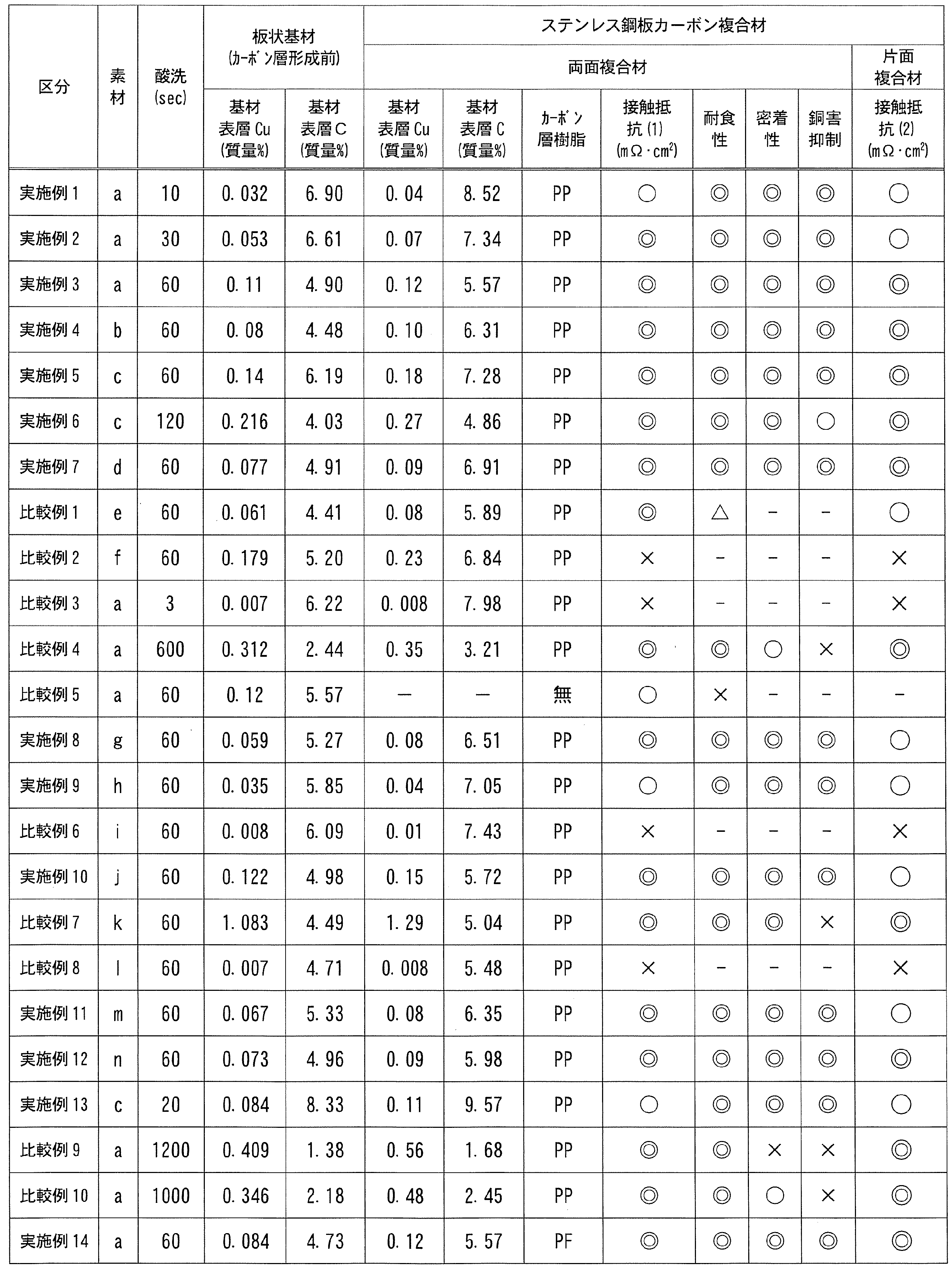
上記の表1及び表2から分かるように、所定の元素(特に、C、Cr及びCu)含有量を有するステンレス鋼製の板状素材a~d、g、h、j、m又はnを用いると共に、表面処理(酸洗処理)の時間を調整することで基材表層に濃化されるCu及びC含有量が特定の範囲内である板状基材を用いた実施例1~14に係るステンレス鋼板カーボン複合材(両面複合材)は、試験例1~5において、接触抵抗(導電性)、耐食性、基材とカーボン層との密着性及び銅害抑制のいずれも良好であった。
Cr含有量が低い板状素材eから得た板状基材を使用した比較例1に係るステンレス鋼板カーボン複合材は、表面処理(酸洗処理)時間の調整により基材表層におけるCu及びC含有量が特定の範囲内であるものの、耐食性が不十分であった。これは、不働態皮膜が十分に形成されていなかったためと推察される。一方、Cr含有量が高い板状素材f又はiから得た板状基材を使用した比較例2及び6に係るステンレス鋼板カーボン複合材は、接触抵抗が高く導電性に劣るものであった。これは、不働態皮膜が過剰に形成されていたためと推察される。
Cu含有量が高い板状素材kから得た板状基材を使用した比較例7に係るステンレス鋼板カーボン複合材では、実施例と同等の表面処理(酸洗処理)であっても、基材表層のCu含有量が高すぎた。また、Cu含有量が低い板状素材lから得た板状基材を使用した比較例8に係るステンレス鋼板カーボン複合材は、実施例と同等の表面処理(酸洗処理)であっても、基材表層のCu含有量が低過ぎた。比較例7では、銅害によるカーボン層の劣化がみられた。比較例8では、接触抵抗が高かった。
所定の元素(特に、C、Cr及びCu)含有量を有する板状素材aを使用した場合であっても、表面処理(酸洗処理)時間が短い板状基材を使用した比較例3に係るステンレス鋼板カーボン複合材は、基材表層のCu含有量が低かった。そのため、接触抵抗が高かった。
反対に、板状素材aを使用し、表面処理(酸洗処理)時間が長い板状基材を使用した比較例4及び比較例10に係るステンレス鋼板カーボン複合材は、基材表層のCu含有量が高かった。そのため、銅害によるカーボン層の劣化が見られた。また、板状素材aを使用し、表面処理(酸洗処理)時間がさらに長かった板状基材を使用した比較例9に係るステンレス鋼板カーボン複合材では、基材表層においてCu含有量が高く、かつC含有量が低かった。そのため、銅害によるカーボン層の劣化がみられ、かつ基材とカーボン層との密着性が不十分であった。
反対に、板状素材aを使用し、表面処理(酸洗処理)時間が長い板状基材を使用した比較例4及び比較例10に係るステンレス鋼板カーボン複合材は、基材表層のCu含有量が高かった。そのため、銅害によるカーボン層の劣化が見られた。また、板状素材aを使用し、表面処理(酸洗処理)時間がさらに長かった板状基材を使用した比較例9に係るステンレス鋼板カーボン複合材では、基材表層においてCu含有量が高く、かつC含有量が低かった。そのため、銅害によるカーボン層の劣化がみられ、かつ基材とカーボン層との密着性が不十分であった。
所定の元素含有量を有する板状素材aを用い、実施例と同等の表面処理(酸洗処理)を行って基材表層のCu及びC含有量が特定の範囲内である板状基材を使用した場合であっても、カーボン層を用いない比較例5においては、耐食性が十分ではなかった。
片面複合材を用いた試験例6〔接触抵抗の評価(2)〕の結果によれば、いずれも、両面複合材を用いた試験例3〔接触抵抗の評価(1)〕の結果と同じ傾向が得られた。すなわち、本実施形態を満たす実施例では、ステンレス材(符号21)との導電性(低接触抵抗)にも優れた結果が得られ、電気化学式水素圧縮機で使用される給電板との接触抵抗を低くできるものであることが確認された。この結果と前述の両面複合材の各結果とを鑑みれば、本実施形態のステンレス鋼板カーボン複合材は、電気化学式水素圧縮機のセパレータとしても好適であることが分かった。
なお、試験例7の結果から、カーボン層を形成する前の各板状基材については、その表面のCu及びCの含有量は、全ての例において、対応するそれぞれのステンレス鋼板カーボン複合材のCu及びCの含有量よりも少ない結果であった。これは、前述したとおりの測定方法の違い(基材表面の測定位置の相違による「測定範囲」の相違)によるものと推測される。
1…ステンレス鋼板カーボン複合材、2…接着剤層、3…カーボン層、4…ステンレス鋼製板状基材、5…燃料電池用セパレータ、6…固体高分子電解質膜、7…アノード(燃料電極)、8…カソード(酸化剤電極)、9…ガスケット、10…単位セル、11…ガス供給排出用溝、12…開口部、13…固定穴、14…試験片、15…カーボンペーパ、16…白金電極、17…固体高分子形燃料電池、20…試験片、21…ステンレス材、23…白金電極、31…プロトン伝導性電解質膜、32…アノード又はカソード、33…セパレータ、34…給電板、100…プレス装置、101…雄型、102…雌型、103…金型、104…機枠、105…油圧シリンダ
Claims (8)
- ステンレス鋼製の板状基材の少なくとも片面に、炭素質材と熱可塑性樹脂又は熱硬化性樹脂からなるマトリックス樹脂とを含むカーボン層が積層されたステンレス鋼板カーボン複合材であり、
前記基材は、少なくとも、炭素(C)を0.001~0.2質量%、クロム(Cr)を9.0質量%以上16.0質量%未満及び銅(Cu)を0.005~1.0質量%含有すると共に、グロー放電発光分光分析法による基材表層の厚み方向の定量元素分析において、以下の(i)で定義される測定範囲のCu含有量が0.010~0.30質量%、及び以下の(ii)で定義される測定範囲のC含有量が2~15質量%である、ステンレス鋼板カーボン複合材。
(i)基材表層において計測されるCuのピーク強度が最大となる位置Pを挟んで、この位置Pにおけるピーク強度(最大ピーク強度)の1/50のピーク強度が計測される基材中心側の位置D1と、この位置D1と同じピーク強度が基材表面側において計測される位置D2とを結ぶ範囲。
(ii)前記位置Pを挟んで、この位置PにおけるCのピーク強度の1/50の強度が計測される基材中心側の位置D3と、基材表面側における前記位置D2とを結ぶ範囲。 - 前記基材は、以下の化学組成を有する、請求項1に記載のステンレス鋼板カーボン複合材。
C:0.001~0.2質量%、
Si:0.01~2.0質量%、
Mn:0.01~2.5質量%、
Al:0.001~0.5質量%、
Cr:9.0質量%以上16.0質量%未満、
Cu:0.005~1.0質量%、
P:0.1質量%以下、
S:0.01質量%以下、
Ni:0~0.3質量%、
Ti:0~2.0質量%、
Mo:0~3.0質量%、
V:0~1.0質量%、
Nb:0~1.0質量%、
W:0~1.0質量%、
Ta:0~1.0質量%、
Sb:0~1.0質量%、
Pb:0~1.0質量%、並びに
残部:Feおよび不純物。 - 請求項1又は2に記載のステンレス鋼板カーボン複合材を用いた燃料電池用セパレータ。
- 請求項3に記載の燃料電池用セパレータを備えた燃料電池用セル。
- 請求項4に記載の燃料電池用セルを備えた燃料電池スタック。
- 請求項1又は2に記載のステンレス鋼板カーボン複合材を用いた電気化学式水素圧縮機用セパレータ。
- 請求項6に記載の電気化学式水素圧縮機用セパレータを備えた電気化学式水素圧縮機。
- ステンレス鋼板であって、
少なくとも、炭素(C)を0.001~0.2質量%、クロム(Cr)を9.0質量%以上16.0質量%未満及び銅(Cu)を0.005~1.0質量%含有すると共に、グロー放電発光分光分析法による表層の厚み方向の定量元素分析において、以下の(i’)で定義される測定範囲のCu含有量が0.008~0.28質量%、及び以下の(ii')で定義される測定範囲のC含有量が1.8~13.5質量%である、ステンレス鋼板。
(i’)前記鋼板の表層において計測されるCuのピーク強度が最大となる位置P’を挟んで、この位置P’におけるピーク強度(最大ピーク強度)の1/50のピーク強度が計測される鋼板中心側の位置D1’と、前記鋼板の表面とを結ぶ範囲。
(ii’)前記位置P’を挟んで、この位置P’におけるCのピーク強度の1/50の強度が計測される鋼板中心側の位置D3’と、前記鋼板の表面とを結ぶ範囲。
Priority Applications (1)
| Application Number | Priority Date | Filing Date | Title |
|---|---|---|---|
| JP2020563024A JP7282103B2 (ja) | 2018-12-26 | 2019-12-09 | ステンレス鋼板カーボン複合材及びその用途等 |
Applications Claiming Priority (2)
| Application Number | Priority Date | Filing Date | Title |
|---|---|---|---|
| JP2018242541 | 2018-12-26 | ||
| JP2018-242541 | 2018-12-26 |
Publications (1)
| Publication Number | Publication Date |
|---|---|
| WO2020137485A1 true WO2020137485A1 (ja) | 2020-07-02 |
Family
ID=71125847
Family Applications (1)
| Application Number | Title | Priority Date | Filing Date |
|---|---|---|---|
| PCT/JP2019/048060 Ceased WO2020137485A1 (ja) | 2018-12-26 | 2019-12-09 | ステンレス鋼板カーボン複合材及びその用途等 |
Country Status (2)
| Country | Link |
|---|---|
| JP (1) | JP7282103B2 (ja) |
| WO (1) | WO2020137485A1 (ja) |
Citations (6)
| Publication number | Priority date | Publication date | Assignee | Title |
|---|---|---|---|---|
| JP2000294256A (ja) * | 1999-04-09 | 2000-10-20 | Sumitomo Metal Ind Ltd | 固体高分子型燃料電池 |
| JP2005089780A (ja) * | 2003-09-12 | 2005-04-07 | Nippon Steel Corp | 成形性及び溶接性に優れる潤滑表面処理金属基材 |
| JP2005166276A (ja) * | 2003-11-28 | 2005-06-23 | Jfe Steel Kk | 固体高分子型燃料電池セパレータ用ステンレス鋼,それを用いた固体高分子型燃料電池セパレータおよび固体高分子型燃料電池 |
| WO2017051810A1 (ja) * | 2015-09-25 | 2017-03-30 | 新日鐵住金株式会社 | 固体高分子形燃料電池用カーボンセパレータ、固体高分子形燃料電池セル、および固体高分子形燃料電池 |
| US20170149036A1 (en) * | 2014-06-25 | 2017-05-25 | Salzgitter Flachstahl Gmbh | Steel product for protecting electrical components from mechanical damage |
| WO2018043285A1 (ja) * | 2016-08-30 | 2018-03-08 | 新日鐵住金株式会社 | フェライト系ステンレス鋼材、セパレーター、セルおよび燃料電池 |
-
2019
- 2019-12-09 WO PCT/JP2019/048060 patent/WO2020137485A1/ja not_active Ceased
- 2019-12-09 JP JP2020563024A patent/JP7282103B2/ja active Active
Patent Citations (6)
| Publication number | Priority date | Publication date | Assignee | Title |
|---|---|---|---|---|
| JP2000294256A (ja) * | 1999-04-09 | 2000-10-20 | Sumitomo Metal Ind Ltd | 固体高分子型燃料電池 |
| JP2005089780A (ja) * | 2003-09-12 | 2005-04-07 | Nippon Steel Corp | 成形性及び溶接性に優れる潤滑表面処理金属基材 |
| JP2005166276A (ja) * | 2003-11-28 | 2005-06-23 | Jfe Steel Kk | 固体高分子型燃料電池セパレータ用ステンレス鋼,それを用いた固体高分子型燃料電池セパレータおよび固体高分子型燃料電池 |
| US20170149036A1 (en) * | 2014-06-25 | 2017-05-25 | Salzgitter Flachstahl Gmbh | Steel product for protecting electrical components from mechanical damage |
| WO2017051810A1 (ja) * | 2015-09-25 | 2017-03-30 | 新日鐵住金株式会社 | 固体高分子形燃料電池用カーボンセパレータ、固体高分子形燃料電池セル、および固体高分子形燃料電池 |
| WO2018043285A1 (ja) * | 2016-08-30 | 2018-03-08 | 新日鐵住金株式会社 | フェライト系ステンレス鋼材、セパレーター、セルおよび燃料電池 |
Also Published As
| Publication number | Publication date |
|---|---|
| JP7282103B2 (ja) | 2023-05-26 |
| JPWO2020137485A1 (ja) | 2021-11-18 |
Similar Documents
| Publication | Publication Date | Title |
|---|---|---|
| KR101597721B1 (ko) | 고체 고분자형 연료 전지 세퍼레이터용 티탄재 및 그 제조 방법 및 이를 이용한 고체 고분자형 연료 전지 | |
| JP6122589B2 (ja) | 燃料電池セパレータ | |
| KR101548064B1 (ko) | 연료 전지 세퍼레이터 | |
| CN102859768B (zh) | 固体高分子型燃料电池间隔件用金属板 | |
| CN100550489C (zh) | 燃料电池用隔板及其制造方法 | |
| WO2012011201A1 (ja) | チタン製燃料電池セパレータ | |
| JP5325235B2 (ja) | 燃料電池用セパレータ材料、それを用いた燃料電池用セパレータ、燃料電池スタック、及び燃料電池セパレータ用材料の製造方法 | |
| CN110249462B (zh) | 燃料电池的隔板用钢板的基材不锈钢板及其制造方法 | |
| JP2003272659A (ja) | 固体高分子型燃料電池用セパレータおよび燃料電池 | |
| KR20140043463A (ko) | 연료 전지용 세퍼레이터 재료, 그것을 사용한 연료 전지용 세퍼레이터 및 연료 전지 스택, 그리고 연료 전지용 세퍼레이터 재료의 제조 방법 | |
| JPH11219713A (ja) | 低温型燃料電池用セパレータ | |
| WO2002039530A1 (en) | Press separator for fuel cell | |
| JP7282103B2 (ja) | ステンレス鋼板カーボン複合材及びその用途等 | |
| CN100472846C (zh) | 燃料电池的金属隔板和包括它的燃料电池 | |
| JP6771351B2 (ja) | ステンレス鋼板カーボン複合材及びその製造方法 | |
| WO2003028134A1 (en) | Separator for fuel cell and method for preparation thereof | |
| JP7448522B2 (ja) | 複合材及びその製造方法、並びに当該複合材を用いた燃料電池用のセパレータ、セル及びスタック | |
| JP2020111806A (ja) | ステンレス鋼板及びその製造方法、燃料電池用セパレータ、燃料電池セル、並びに燃料電池スタック | |
| JP7257793B2 (ja) | ステンレス鋼板、燃料電池用セパレータ、燃料電池セル、及び燃料電池スタック | |
| JP5419271B2 (ja) | 燃料電池用セパレータ材料、それを用いた燃料電池用セパレータ、燃料電池スタック及び燃料電池用セパレータ材料の製造方法 | |
| JP6970495B2 (ja) | ステンレス鋼板カーボン複合材及びその製造方法 | |
| JP2008504437A (ja) | ステンレス鋼合金及び二極式プレート | |
| JP2011249148A (ja) | 燃料電池用セパレータ材料、それを用いた燃料電池用セパレータ及び燃料電池スタック、並びに燃料電池用セパレータ材料の製造方法 | |
| JP2004071319A (ja) | 燃料電池用金属製セパレータ用素材板およびそれを使用した燃料電池用金属製セパレータ | |
| WO2003083980A1 (en) | Metal separator for fuel cell and manufacturing method thereof |
Legal Events
| Date | Code | Title | Description |
|---|---|---|---|
| 121 | Ep: the epo has been informed by wipo that ep was designated in this application |
Ref document number: 19903688 Country of ref document: EP Kind code of ref document: A1 |
|
| ENP | Entry into the national phase |
Ref document number: 2020563024 Country of ref document: JP Kind code of ref document: A |
|
| NENP | Non-entry into the national phase |
Ref country code: DE |
|
| 122 | Ep: pct application non-entry in european phase |
Ref document number: 19903688 Country of ref document: EP Kind code of ref document: A1 |