WO2020137306A1 - 基板処理方法および基板処理装置 - Google Patents
基板処理方法および基板処理装置 Download PDFInfo
- Publication number
- WO2020137306A1 WO2020137306A1 PCT/JP2019/046026 JP2019046026W WO2020137306A1 WO 2020137306 A1 WO2020137306 A1 WO 2020137306A1 JP 2019046026 W JP2019046026 W JP 2019046026W WO 2020137306 A1 WO2020137306 A1 WO 2020137306A1
- Authority
- WO
- WIPO (PCT)
- Prior art keywords
- substrate
- sublimable substance
- liquid
- solid
- drying treatment
- Prior art date
- Legal status (The legal status is an assumption and is not a legal conclusion. Google has not performed a legal analysis and makes no representation as to the accuracy of the status listed.)
- Ceased
Links
Images














Classifications
-
- H—ELECTRICITY
- H10—SEMICONDUCTOR DEVICES; ELECTRIC SOLID-STATE DEVICES NOT OTHERWISE PROVIDED FOR
- H10P—GENERIC PROCESSES OR APPARATUS FOR THE MANUFACTURE OR TREATMENT OF DEVICES COVERED BY CLASS H10
- H10P72/00—Handling or holding of wafers, substrates or devices during manufacture or treatment thereof
- H10P72/04—Apparatus for manufacture or treatment
- H10P72/0448—Apparatus for applying a liquid, a resin, an ink or the like
-
- H—ELECTRICITY
- H10—SEMICONDUCTOR DEVICES; ELECTRIC SOLID-STATE DEVICES NOT OTHERWISE PROVIDED FOR
- H10P—GENERIC PROCESSES OR APPARATUS FOR THE MANUFACTURE OR TREATMENT OF DEVICES COVERED BY CLASS H10
- H10P52/00—Grinding, lapping or polishing of wafers, substrates or parts of devices
-
- H—ELECTRICITY
- H10—SEMICONDUCTOR DEVICES; ELECTRIC SOLID-STATE DEVICES NOT OTHERWISE PROVIDED FOR
- H10P—GENERIC PROCESSES OR APPARATUS FOR THE MANUFACTURE OR TREATMENT OF DEVICES COVERED BY CLASS H10
- H10P70/00—Cleaning of wafers, substrates or parts of devices
- H10P70/20—Cleaning during device manufacture
-
- H—ELECTRICITY
- H10—SEMICONDUCTOR DEVICES; ELECTRIC SOLID-STATE DEVICES NOT OTHERWISE PROVIDED FOR
- H10P—GENERIC PROCESSES OR APPARATUS FOR THE MANUFACTURE OR TREATMENT OF DEVICES COVERED BY CLASS H10
- H10P72/00—Handling or holding of wafers, substrates or devices during manufacture or treatment thereof
- H10P72/04—Apparatus for manufacture or treatment
- H10P72/0402—Apparatus for fluid treatment
- H10P72/0404—Apparatus for fluid treatment for general liquid treatment, e.g. etching followed by cleaning
-
- H—ELECTRICITY
- H10—SEMICONDUCTOR DEVICES; ELECTRIC SOLID-STATE DEVICES NOT OTHERWISE PROVIDED FOR
- H10P—GENERIC PROCESSES OR APPARATUS FOR THE MANUFACTURE OR TREATMENT OF DEVICES COVERED BY CLASS H10
- H10P72/00—Handling or holding of wafers, substrates or devices during manufacture or treatment thereof
- H10P72/04—Apparatus for manufacture or treatment
- H10P72/0402—Apparatus for fluid treatment
- H10P72/0406—Apparatus for fluid treatment for cleaning followed by drying, rinsing, stripping, blasting or the like
- H10P72/0408—Apparatus for fluid treatment for cleaning followed by drying, rinsing, stripping, blasting or the like for drying
-
- H—ELECTRICITY
- H10—SEMICONDUCTOR DEVICES; ELECTRIC SOLID-STATE DEVICES NOT OTHERWISE PROVIDED FOR
- H10P—GENERIC PROCESSES OR APPARATUS FOR THE MANUFACTURE OR TREATMENT OF DEVICES COVERED BY CLASS H10
- H10P72/00—Handling or holding of wafers, substrates or devices during manufacture or treatment thereof
- H10P72/04—Apparatus for manufacture or treatment
- H10P72/0402—Apparatus for fluid treatment
- H10P72/0406—Apparatus for fluid treatment for cleaning followed by drying, rinsing, stripping, blasting or the like
- H10P72/0411—Apparatus for fluid treatment for cleaning followed by drying, rinsing, stripping, blasting or the like for wet cleaning or washing
- H10P72/0414—Apparatus for fluid treatment for cleaning followed by drying, rinsing, stripping, blasting or the like for wet cleaning or washing using mainly spraying means, e.g. nozzles
-
- H—ELECTRICITY
- H10—SEMICONDUCTOR DEVICES; ELECTRIC SOLID-STATE DEVICES NOT OTHERWISE PROVIDED FOR
- H10P—GENERIC PROCESSES OR APPARATUS FOR THE MANUFACTURE OR TREATMENT OF DEVICES COVERED BY CLASS H10
- H10P72/00—Handling or holding of wafers, substrates or devices during manufacture or treatment thereof
- H10P72/04—Apparatus for manufacture or treatment
- H10P72/0431—Apparatus for thermal treatment
-
- H—ELECTRICITY
- H10—SEMICONDUCTOR DEVICES; ELECTRIC SOLID-STATE DEVICES NOT OTHERWISE PROVIDED FOR
- H10P—GENERIC PROCESSES OR APPARATUS FOR THE MANUFACTURE OR TREATMENT OF DEVICES COVERED BY CLASS H10
- H10P72/00—Handling or holding of wafers, substrates or devices during manufacture or treatment thereof
- H10P72/06—Apparatus for monitoring, sorting, marking, testing or measuring
- H10P72/0604—Process monitoring, e.g. flow or thickness monitoring
-
- H—ELECTRICITY
- H10—SEMICONDUCTOR DEVICES; ELECTRIC SOLID-STATE DEVICES NOT OTHERWISE PROVIDED FOR
- H10P—GENERIC PROCESSES OR APPARATUS FOR THE MANUFACTURE OR TREATMENT OF DEVICES COVERED BY CLASS H10
- H10P74/00—Testing or measuring during manufacture or treatment of wafers, substrates or devices
- H10P74/20—Testing or measuring during manufacture or treatment of wafers, substrates or devices characterised by the properties tested or measured, e.g. structural or electrical properties
- H10P74/203—Structural properties, e.g. testing or measuring thicknesses, line widths, warpage, bond strengths or physical defects
-
- H—ELECTRICITY
- H10—SEMICONDUCTOR DEVICES; ELECTRIC SOLID-STATE DEVICES NOT OTHERWISE PROVIDED FOR
- H10P—GENERIC PROCESSES OR APPARATUS FOR THE MANUFACTURE OR TREATMENT OF DEVICES COVERED BY CLASS H10
- H10P74/00—Testing or measuring during manufacture or treatment of wafers, substrates or devices
- H10P74/23—Testing or measuring during manufacture or treatment of wafers, substrates or devices characterised by multiple measurements, corrections, marking or sorting processes
Definitions
- the present invention relates to a substrate processing method and a substrate processing apparatus for processing a substrate.
- Substrates include, for example, semiconductor wafers, FPD (Flat Panel Display) substrates for liquid crystal display devices and organic EL (electroluminescence) display devices, optical disk substrates, magnetic disk substrates, magneto-optical disk substrates, photomask substrates. , Ceramic substrates, substrates for solar cells, and the like.
- substrates such as semiconductor wafers and glass substrates for FPDs are processed as needed.
- processing includes supplying a processing liquid such as a chemical liquid or a rinse liquid to the substrate. After the processing liquid is supplied, the processing liquid is removed from the substrate and the substrate is dried.
- spin drying is performed to dry the substrates by removing the liquid on the substrates by high-speed rotation of the substrates.
- the force caused by the surface tension of the processing liquid adhering to the substrate may be applied to the pattern, and the pattern may collapse.
- IPA isopropyl alcohol
- a hydrophobizing agent which makes the contact angle of the liquid to the pattern approach 90 degrees to the substrate.
- Patent Document 1 discloses a substrate processing method and a substrate processing apparatus for performing sublimation drying.
- sublimation drying described in Patent Document 1 a solution of a sublimable substance is supplied to the upper surface of a substrate, and DIW (deionized water) on the substrate is replaced with a solution of the sublimable substance.
- DIW deionized water
- the solvent of the sublimable substance is evaporated to deposit the sublimable substance.
- a film made of a solid sublimable substance is formed on the upper surface of the substrate.
- the substrate is heated.
- the sublimable substance on the substrate sublimes and is removed from the substrate.
- sublimation drying has a lower pattern collapse rate than conventional drying methods such as spin drying in which liquid is removed by high-speed rotation of the substrate and IPA drying using IPA.
- spin drying in which liquid is removed by high-speed rotation of the substrate and IPA drying using IPA.
- the strength of the pattern is extremely low, the collapse of the pattern may not be sufficiently prevented even if sublimation drying is performed.
- one of the causes is the thickness of a film made of a solid sublimable substance.
- the thickness of the solid of the sublimable substance corresponds to the thickness of the solution of the sublimable substance when the saturated concentration of the sublimable substance is reached. If the concentration of the sublimable substance in the solution of the sublimable substance can be known before reaching the saturation concentration of the sublimable substance, the thickness of the solid substance of the sublimable substance can be predicted, and the solid substance of the sublimable substance with an inappropriate thickness can be predicted. Formation can be avoided.
- one of the objects of the present invention is to provide a substrate processing method and a substrate processing apparatus capable of reducing the pattern collapse rate that occurs when sublimable substances are removed from the upper surface of a substrate by sublimation. ..
- a pre-drying treatment liquid which is a solution in which a sublimable substance is dissolved in a solvent, is supplied to an upper surface of a substrate on which a pattern is formed, and a liquid film of the pre-drying treatment liquid is applied to the substrate.
- the concentration of the sublimable substance in the liquid film is a reference concentration based on a film thickness reduction rate that is a rate at which the thickness of the liquid film is reduced by evaporation of the solvent.
- the solution in which the sublimable substance is dissolved in the solvent is supplied to the upper surface of the substrate.
- a liquid film of the pre-drying treatment liquid is formed on the upper surface of the substrate.
- the solvent is evaporated from the liquid film of the pre-drying treatment liquid.
- the concentration of the sublimable substance in the liquid film of the pre-drying treatment liquid increases as the solvent evaporates.
- solids of the sublimable substance are deposited in the liquid film of the pretreatment liquid for drying.
- the inventors of the present application have found that there is a correlation between the film thickness reduction rate and the concentration of the sublimable substance in the liquid film. Therefore, if it is determined whether or not the concentration of the sublimable substance in the liquid film is within the reference concentration range based on the rate of decrease of the thickness of the liquid film of the pre-drying liquid in the deposition step, the solid of the sublimable substance is determined. It is possible to determine whether or not the concentration of the sublimable substance in the liquid film is within the reference concentration range before the deposition of the sublimable substance, that is, before the concentration of the sublimable substance reaches the saturation concentration of the sublimable substance. ..
- the substrate processing is interrupted to prevent the sublimable substance of an inappropriate thickness from being sublimated. be able to. This can suppress an increase in the pattern collapse rate.
- the concentration determination step compares the sublimability in the liquid film by comparing pre-measured reference data with the film thickness reduction rate measured during the deposition step. It includes the step of estimating the concentration of the substance. Therefore, the concentration of the sublimable substance in the liquid film can be easily estimated during the deposition process.
- the sublimation step is performed.
- the method further includes a pre-drying treatment liquid removing step of removing the pre-drying treatment liquid from the upper surface of the substrate by supplying a removing liquid to the upper surface of the substrate before the solid of the volatile substance is deposited.
- the sublimable substance when the concentration of the sublimable substance in the liquid film is not within the standard concentration range, the sublimable substance is removed from the upper surface of the substrate by the removing liquid before the solid of the sublimable substance is deposited. You can This can prevent the solid of the sublimable substance having an inappropriate thickness from being formed on the upper surface of the substrate. Therefore, an increase in the pattern collapse rate can be suppressed. Further, since the pretreatment liquid for drying on the upper surface of the substrate is removed, the substrate can be reused.
- the substrate treatment method when the concentration determination step determines that the concentration of the sublimable substance in the liquid film is lower than a lower limit value of the reference concentration range, the deposition The method further includes a solvent evaporation promoting step of promoting evaporation of the solvent from the liquid film during execution of the step.
- the concentration determination step when it is determined that the concentration of the sublimable substance in the liquid film of the pre-drying treatment liquid is lower than the lower limit value of the reference concentration range, The evaporation of the solvent is accelerated.
- the concentration of the sublimable substance in the liquid film of the pre-drying treatment liquid increases. Therefore, the concentration of the sublimable substance in the liquid film of the pre-drying treatment liquid can be adjusted within the standard concentration range.
- the solvent evaporation promoting step includes a step of removing the vapor of the solvent from the atmosphere in contact with the liquid film by supplying an inert gas toward the atmosphere in contact with the liquid film.
- the vapor of the solvent is removed from the atmosphere in contact with the liquid film of the pre-drying treatment liquid on the upper surface of the substrate by supplying the inert gas. Therefore, evaporation of the solvent from the liquid film of the pre-drying treatment liquid can be promoted.
- the substrate processing method in the deposition step, a substrate rotating step of rotating the upper surface of the substrate around a rotation axis along a vertical direction, and a concentration determination step in the liquid film in the liquid film.
- a concentration determination step in the liquid film in the liquid film.
- the concentration of the sublimable substance in the liquid film of the pre-drying treatment liquid is higher than the upper limit value of the reference concentration range, the solid thickness of the sublimable substance immediately before sublimation becomes larger than the intended value.
- the thickness of the liquid film of the pre-drying treatment liquid on the substrate is reduced, the amount of the sublimable substance contained in the liquid film of the pre-drying treatment liquid is reduced, so that the solid thickness of the sublimable substance is also reduced.
- the rotation speed of the substrate is increased to form the liquid film of the pre-drying treatment liquid on the upper surface of the substrate.
- a centrifugal force it is possible to reduce the thickness of the liquid film of the dry pretreatment liquid before the solid of the sublimable substance is deposited.
- the solid of the sublimable substance having an intended thickness can be deposited. Therefore, even if it is determined in the concentration determination step that the concentration of the sublimable substance in the liquid film of the pre-drying treatment liquid is higher than the upper limit value of the reference concentration range, it is possible to obtain a substrate with a reduced pattern collapse rate. it can.
- the deposition when the substrate processing method determines that the concentration of the sublimable substance in the liquid film is higher than an upper limit value of the reference concentration range in the concentration determination step, the deposition is performed.
- the method further includes a solvent evaporation suppressing step of suppressing evaporation of the solvent from the liquid film during execution of the step.
- the concentration of the sublimable substance in the liquid film is determined to be higher than the upper limit value of the reference concentration range in the concentration determination step, the evaporation of the solvent from the liquid film of the pretreatment liquid for drying is suppressed.
- the proportion of the sublimable substance in the substance evaporated from the liquid film increases. This reduces the concentration of the sublimable substance in the liquid film of the pre-drying treatment liquid. Therefore, the concentration of the sublimable substance in the liquid film of the pre-drying treatment liquid can be adjusted within the standard concentration range.
- the solvent evaporation suppressing step includes a step of suppressing evaporation of the solvent from the liquid film by supplying vapor or mist of the solvent to an atmosphere in contact with the liquid film.
- the amount of the solvent present in the atmosphere in contact with the liquid film of the pre-drying treatment liquid is supplied by supplying the solvent vapor or mist to the atmosphere in contact with the liquid film of the pre-drying treatment liquid on the upper surface of the substrate. Will increase. Therefore, evaporation of the solvent from the liquid film of the pre-drying treatment liquid is suppressed.
- the substrate processing method notifies an abnormality when the concentration determination step determines that the concentration of the sublimable substance in the liquid film is not within the reference concentration range.
- An abnormality notification step is further included. Therefore, it is possible to determine whether or not to continue the substrate processing at an appropriate timing based on the notification of the abnormality.
- the substrate processing method in the deposition step, immediately before the solid of the sublimable substance is deposited by evaporation of the solvent, a film thickness measurement step of measuring the thickness of the liquid film,
- the method further includes a thickness determining step of determining whether or not the thickness of the liquid film measured in the film thickness measuring step is within a reference thickness range of the solid of the sublimable substance.
- the thickness of the liquid film is the standard thickness range of the solid of the sublimable substance. It is determined whether or not This makes it possible to determine whether the solid thickness of the sublimable substance formed on the upper surface of the substrate is appropriate.
- a sublimable substance solid having an appropriate thickness is formed after the completion of the deposition step. Therefore, a substrate having a reduced pattern collapse rate can be obtained.
- the substrate processing method determines that the thickness of the liquid film measured in the film thickness measurement step is not within the reference thickness range in the thickness determination step, an abnormality is notified.
- the second abnormality notifying step is further included. Therefore, it is possible to determine whether or not to continue the substrate processing at an appropriate timing based on the notification of the abnormality.
- the substrate processing method comprises: evaporating the solvent from the pre-drying treatment liquid on the upper surface of the substrate to remove the solid of the sublimable substance on the upper surface of the substrate.
- the said precipitation process is the said 1st precipitation process, and the said sublimation process is performed after completion
- the first dissolution step is executed when it is determined in the thickness determination step that the thickness of the liquid film is within the reference thickness range.
- the pre-drying treatment liquid remains on the upper surface of the substrate.
- the first dissolution step at least a part of the solid of the sublimable substance is dissolved in the pretreatment liquid for drying.
- the solvent is evaporated again from the pretreatment liquid for drying. As a result, the content of the solvent is reduced and the solid of the sublimable substance is deposited on the upper surface of the substrate.
- the dry pretreatment liquid exists not only between the patterns but also above the patterns.
- the pattern interval is narrow.
- the pre-drying treatment liquid between the patterns is the bulk of the pre-drying treatment liquid, that is, the pre-drying treatment located in the range from the surface of the pre-drying treatment liquid on the upper surface of the substrate to the upper surface of the pattern. It has different properties from liquid. The difference in properties between the two becomes more remarkable as the space between the patterns becomes narrower.
- the pattern spacing is narrow, when the sublimable substance solid is first deposited, the sublimable substance solid is deposited only in the bulk of the dry pretreatment liquid, and the sublimable substance solid does not exist between the patterns.
- an almost nonexistent incomplete deposition region may be formed in the upper surface of the substrate.
- the surface tension of the pre-drying treatment liquid between the patterns is applied to the side surface of the pattern, when the solid of the sublimable substance sublimes, the pattern in the incomplete deposition region may collapse. This causes an increase (deterioration) in the pattern collapse rate.
- the precipitated sublimable substance solids are dissolved in the dry pretreatment liquid, and then the sublimable substance solids are precipitated again, the solids of the sublimable substance also enter a narrow space such as a space between the patterns. Crystal nuclei are formed. Therefore, if the sublimable substance solids deposited in the first dissolution step are dissolved in the pre-drying treatment liquid and the sublimable substance solids are deposited again in the final deposition step, the pattern spacing may be narrow. Also, it is possible to prevent the generation of the incompletely deposited region or reduce the area thereof.
- the first dissolution step is started when the thickness of the liquid film of the pre-drying treatment liquid is determined to be within the reference thickness range in the thickness determination step. That is, the first melting step is started by the formation of the solid of the sublimable substance having an appropriate thickness. Therefore, the first melting step, the final precipitation step, and the sublimation step are performed only when the sublimable substance solid having an appropriate thickness is formed. After the sublimation process is completed, a substrate having a reduced pattern collapse rate can be obtained.
- the substrate treatment is performed without performing the steps (the first dissolution step, the final precipitation step, and the sublimation step) after the first precipitation step. It can be interrupted early.
- the substrate processing method comprises: evaporating the solvent from the pre-drying treatment liquid on the upper surface of the substrate to remove the solid of the sublimable substance on the upper surface of the substrate.
- a first deposition step of depositing in a pre-drying treatment liquid a first dissolving step of dissolving at least a part of the solid of the sublimable substance in the pre-drying treatment liquid on the upper surface of the substrate, and the sublimable substance
- a final deposition step of depositing the solid of the sublimable substance on the upper surface of the substrate by evaporating the solvent from the dry pretreatment liquid in which the solid is dissolved.
- the precipitation step includes at least one of the first precipitation step and the final precipitation step, and the sublimation step is performed after the final precipitation step.
- the precipitated sublimable substance solid is dissolved in the dry pretreatment liquid, and then the sublimable substance solid is precipitated again. Therefore, even when the pattern interval is narrow, it is possible to prevent the generation of incompletely deposited regions and reduce the area thereof. Thereby, the collapse of the pattern can be reduced, and the collapse rate of the pattern can be reduced.
- the concentration of the sublimable substance in the liquid film is within the reference concentration range.
- a solid substance of the sublimable substance having an appropriate thickness is formed. Then, since the solid of the sublimable substance is sublimated after the final deposition step, it is possible to obtain a substrate with a reduced pattern collapse rate.
- the substrate processing is interrupted to prevent the sublimable substance of an inappropriate thickness from being sublimated. be able to. This can suppress an increase in the pattern collapse rate.
- the pattern collapse rate depends on the thickness of the solid of the sublimable substance finally formed on the upper surface of the substrate, so the concentration determination step is preferably performed in the final deposition step.
- the amount of solvent evaporated in the first dissolution step and the final precipitation step is predictable. Therefore, even when the concentration determination step is performed in the first precipitation step, the solid of the sublimable substance formed on the upper surface of the substrate based on the concentration of the sublimable substance in the liquid film during the first precipitation step. It is possible to determine whether or not the thickness of is appropriate.
- a pre-drying treatment liquid which is a solution in which a sublimable substance is dissolved in a solvent, is supplied to an upper surface of a substrate on which a pattern is formed, and a liquid film of the pre-drying treatment liquid is formed into the liquid film.
- a pre-drying treatment liquid supply step of forming on the upper surface of the substrate a deposition step of depositing the solid of the sublimable substance on the upper surface of the substrate by evaporating the solvent from the liquid film, and in the deposition step.
- the solution in which the sublimable substance is dissolved in the solvent is supplied to the upper surface of the substrate.
- a liquid film of the pre-drying treatment liquid is formed on the upper surface of the substrate.
- the solvent is evaporated from the liquid film of the pre-drying treatment liquid.
- the concentration of the sublimable substance in the liquid film of the pre-drying treatment liquid increases as the solvent evaporates.
- solids of the sublimable substance are deposited in the liquid film of the pretreatment liquid for drying.
- the collapse rate of the pattern at that part may increase. Therefore, the flatness of the surface of the solid of the sublimable substance deposited on the upper surface of the substrate is measured to determine whether or not the measured flatness is within the reference flat range. Thus, it is possible to check whether or not a solid sublimable substance having a uniform thickness is formed on the entire upper surface of the substrate.
- the solid of the sublimable substance When it is determined that the flatness of the solid of the sublimable substance is within the standard flat range, the solid of the sublimable substance is sublimated, so that a substrate having a reduced pattern collapse rate can be obtained. On the other hand, when it is determined that the degree of flatness of the solid of the sublimable substance is not within the reference flat range, the substrate processing is interrupted, so that it is possible to suppress the generation of the substrate having the increased pattern collapse rate.
- the substrate processing method supplies a removing liquid to the upper surface of the substrate when it is determined in the flatness measuring step that the flatness is not within the reference flat range.
- the method further includes a solid removal step of removing solids of the sublimable substance from the upper surface of the substrate.
- the solid of the sublimable substance when the flatness of the solid of the sublimable substance is not within the standard flat range, the solid of the sublimable substance is removed from the upper surface of the substrate by the removing liquid. Therefore, even when a part of the solid of the sublimable substance has an excessively thin portion or an excessively thick portion, the collapse of the pattern can be suppressed. Further, since the solid of the sublimable substance on the upper surface of the substrate is removed, the substrate can be reused.
- a sub-sublimation substance is a solution prepared by dissolving the pre-drying liquid in a solvent so that the liquid film is formed on the upper surface of the substrate on which the pattern is formed.
- a substrate processing apparatus is provided. According to this configuration, the same effect as that of the substrate processing method described above is obtained.
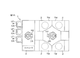
- FIG. 1A is a schematic view of a substrate processing apparatus according to an embodiment of the present invention viewed from above.
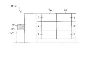
- FIG. 1B is a schematic view of the substrate processing apparatus viewed from the side.
- FIG. 2 is a schematic view in which the inside of a processing unit provided in the substrate processing apparatus is viewed horizontally.
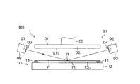
- FIG. 3 is a schematic view in which the film thickness measuring unit, the spin chuck, and the blocking member provided in the processing unit are viewed horizontally.
- FIG. 4 is a schematic view of the film thickness measuring unit and the spin chuck as viewed from above.
- FIG. 5 is a cross-sectional view showing the inside of a housing that accommodates the light emitting element included in the film thickness measurement unit.
- FIG. 6 is a sectional view taken along line VI-VI shown in FIG.
- FIG. 7 is a schematic view showing a pre-drying treatment liquid supply device provided in the substrate treatment device.
- FIG. 8 is a block diagram showing hardware of a controller included in the substrate processing apparatus.
- FIG. 9 is a flow chart for explaining an example of substrate processing by the substrate processing apparatus.
- FIG. 10A is a schematic diagram showing a state of a substrate when a solution of camphor and IPA is used.
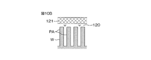
- FIG. 10B is a schematic diagram showing a state of the substrate when a solution of camphor and IPA is used.
- FIG. 10C is a schematic diagram showing a state of a substrate when a solution of camphor and IPA is used.
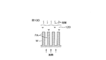
- FIG. 10D is a schematic diagram showing a state of a substrate when a solution of camphor and IPA is used.
- FIG. 10A is a schematic diagram showing a state of a substrate when a solution of camphor and IPA is used.
- FIG. 10B is a schematic diagram showing a state of the substrate when a solution of
- FIG. 10E is a schematic diagram showing a state of a substrate when a solution of camphor and IPA is used.
- FIG. 10F is a schematic diagram showing the state of the substrate when a solution of camphor and IPA is used.
- FIG. 11 is an equilibrium diagram of camphor and IPA.
- FIG. 12A is a schematic diagram showing a state of a substrate when a solution of camphor and methanol is used.
- FIG. 12B is a schematic diagram showing a state of the substrate when camphor and a solution of methanol are used.
- FIG. 12C is a schematic diagram showing the state of the substrate when a solution of camphor and methanol is used.
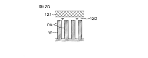
- FIG. 12D is a schematic diagram showing the state of the substrate when camphor and a solution of methanol are used.
- FIG. 12A is a schematic diagram showing a state of a substrate when a solution of camphor and methanol is used.
- FIG. 12B is a schematic diagram showing a state of the substrate
- FIG. 13 is a graph showing the collapse rate of the pattern.
- FIG. 14 is a graph showing the change over time in the thickness of the liquid film of the pre-drying treatment liquid on the upper surface of the substrate until the solid of the sublimable substance is deposited from the pre-drying treatment liquid.
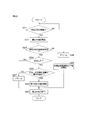
- FIG. 15 is a flowchart showing the flow of the first example of the film thickness monitoring step.
- FIG. 16 is a schematic diagram for explaining the abnormality processing step in the first example of the film thickness monitoring step.
- FIG. 17 is a flowchart showing the flow of the second example of the film thickness monitoring step.
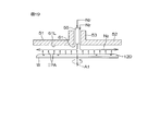
- FIG. 18 is a schematic diagram for explaining the solvent evaporation suppressing step in the second example of the film thickness monitoring step.
- FIG. 19 is a schematic diagram for explaining the solvent evaporation promoting step in the second example of the film thickness monitoring step.
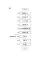
- FIG. 20 is a flowchart showing the flow of the third example of the film thickness monitoring step.
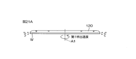
- FIG. 21A is a schematic diagram for explaining the thinning step in the third example of the film thickness monitoring step.
- FIG. 21B is a schematic diagram for explaining the thinning step in the third example of the film thickness monitoring step.
- FIG. 22 is a flowchart showing the flow of the fourth example of the film thickness monitoring step.
- FIG. 23 is a flow chart for explaining another example of substrate processing by the substrate processing apparatus.
- FIG. 24 is a flowchart showing the flow of the fifth example of the film thickness monitoring step.
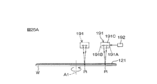
- FIG. 25A is a schematic diagram for explaining a flatness measuring step in the substrate processing.
- FIG. 25B is a schematic diagram for explaining the solid removal step in the substrate processing.
- FIG. 25C is a schematic diagram for explaining a solid removal step in the substrate processing
- the atmospheric pressure in the substrate processing apparatus 1 is maintained at the atmospheric pressure (for example, 1 atmospheric pressure or a value in the vicinity thereof) in the clean room in which the substrate processing apparatus 1 is installed, unless otherwise specified. ..
- FIG. 1A is a schematic view of a substrate processing apparatus 1 according to an embodiment of the present invention viewed from above.
- FIG. 1B is a schematic view of the substrate processing apparatus 1 viewed from the side.
- the substrate processing apparatus 1 is a single-wafer processing apparatus that processes disk-shaped substrates W such as semiconductor wafers one by one.
- the substrate processing apparatus 1 processes a load port LP that holds a carrier CA that contains a substrate W and a substrate W that is transported from the carrier CA on the load port LP with a processing fluid such as a processing liquid or a processing gas.
- the unit 2 includes a transfer robot that transfers a substrate W between the carrier CA on the load port LP and the processing unit 2, and a controller 3 that controls the substrate processing apparatus 1.
- the transfer robot includes an indexer robot IR for loading and unloading the substrate W with respect to the carrier CA on the load port LP, and a center robot CR for loading and unloading the substrate W with respect to the plurality of processing units 2.
- the indexer robot IR transfers the substrate W between the load port LP and the center robot CR, and the center robot CR transfers the substrate W between the indexer robot IR and the processing unit 2.
- the center robot CR includes a hand H1 that supports the substrate W, and the indexer robot IR includes a hand H2 that supports the substrate W.
- the plurality of processing units 2 form a plurality of towers TW arranged around the center robot CR in plan view.
- FIG. 1A shows an example in which four towers TW are formed.
- the center robot CR can access any of the towers TW.
- each tower TW includes a plurality (for example, three) of processing units 2 stacked vertically.
- FIG. 2 is a schematic view of the inside of the processing unit 2 provided in the substrate processing apparatus 1 as viewed horizontally.
- the processing unit 2 is a wet processing unit 2w that supplies a processing liquid to the substrate W.
- the processing unit 2 includes a box-shaped chamber 4 having an internal space, and a spin for holding one substrate W horizontally in the chamber 4 and rotating it about a vertical rotation axis A1 passing through the central portion of the upper surface of the substrate W. It includes a chuck 10 and a cylindrical processing cup 21 surrounding the spin chuck 10 around a rotation axis A1.
- the chamber 4 includes a box-shaped partition wall 5 provided with a loading/unloading port 5b through which the substrate W passes, and a shutter 7 for opening/closing the loading/unloading port 5b.
- the FFU 6 (fan filter unit) is arranged on the blower port 5 a provided on the partition wall 5.
- the FFU 6 constantly supplies clean air (air filtered by a filter) into the chamber 4 from the air outlet 5a.
- the gas in the chamber 4 is exhausted from the chamber 4 through the exhaust duct 8 connected to the bottom of the processing cup 21. As a result, a downflow of clean air is always formed in the chamber 4.
- the flow rate of the exhaust gas discharged to the exhaust duct 8 is changed according to the opening degree of the exhaust valve 9 arranged in the exhaust duct 8.
- the spin chuck 10 includes a disk-shaped spin base 12 held in a horizontal posture, a plurality of chuck pins 11 holding the substrate W in a horizontal posture above the spin base 12, and a central portion of the spin base 12.
- a spin shaft 13 extending downward and a spin motor 14 for rotating the spin base 12 and the plurality of chuck pins 11 by rotating the spin shaft 13 are included.
- the spin chuck 10 is not limited to a sandwich type chuck in which the plurality of chuck pins 11 are brought into contact with the outer peripheral surface of the substrate W, but the back surface (lower surface) of the substrate W that is a non-device forming surface is attracted to the upper surface 12u of the spin base 12. It may be a vacuum chuck that holds the substrate W horizontally.
- the processing cup 21 includes a plurality of guards 24 for receiving the processing liquid discharged from the substrate W, a plurality of cups 23 for receiving the processing liquid guided downward by the plurality of guards 24, a plurality of guards 24, and a plurality of guards 24. And a cylindrical outer wall member 22 that surrounds the cup 23.
- FIG. 2 shows an example in which four guards 24 and three cups 23 are provided, and the outermost cup 23 is integrated with the third guard 24 from the top.
- the guard 24 includes a cylindrical portion 25 that surrounds the spin chuck 10, and an annular ceiling portion 26 that extends obliquely upward from the upper end of the cylindrical portion 25 toward the rotation axis A1.
- the plurality of ceiling portions 26 are vertically stacked, and the plurality of cylindrical portions 25 are concentrically arranged.
- the annular upper end of the ceiling portion 26 corresponds to the upper end 24u of the guard 24 surrounding the substrate W and the spin base 12 in a plan view.
- the plurality of cups 23 are arranged below the plurality of cylindrical portions 25, respectively.
- the cup 23 has an annular liquid receiving groove for receiving the processing liquid guided downward by the guard 24.
- the processing unit 2 includes a guard lifting unit 27 that lifts and lowers the plurality of guards 24 individually.
- the guard lifting unit 27 positions the guard 24 at any position from the upper position to the lower position.
- the guard lifting unit 27 is also called a guard lifter.
- FIG. 2 shows a state in which the two guards 24 are arranged at the upper position and the remaining two guards 24 are arranged at the lower position.
- the upper position is a position where the upper end 24u of the guard 24 is arranged above a holding position where the substrate W held by the spin chuck 10 is arranged.
- the lower position is a position where the upper end 24u of the guard 24 is arranged below the holding position.
- At least one guard 24 is arranged at the upper position.
- the processing liquid supplied to the substrate W is shaken off around the substrate W.
- the shaken-off processing liquid collides with the inner surface of the guard 24 horizontally facing the substrate W, and is guided to the cup 23 corresponding to the guard 24.
- the processing liquid discharged from the substrate W is collected in the processing cup 21.
- the processing unit 2 includes a plurality of nozzles that eject the processing liquid toward the substrate W held by the spin chuck 10.
- the plurality of nozzles are a chemical liquid nozzle 31 that discharges a chemical liquid toward the upper surface of the substrate W, a rinse liquid nozzle 35 that discharges a rinse liquid toward the upper surface of the substrate W, and a pre-drying treatment liquid toward the upper surface of the substrate W.
- the chemical liquid nozzle 31 may be a scan nozzle that can move horizontally in the chamber 4 or a fixed nozzle fixed to the partition wall 5 of the chamber 4. The same applies to the rinse liquid nozzle 35, the pre-drying treatment liquid nozzle 39, and the replacement liquid nozzle 43.
- the chemical liquid nozzle 31, the rinse liquid nozzle 35, the pre-drying treatment liquid nozzle 39, and the replacement liquid nozzle 43 are scan nozzles, and four nozzle moving units corresponding to these four nozzles are provided. An example is shown.
- the chemical liquid nozzle 31 is connected to a chemical liquid pipe 32 that guides the chemical liquid to the chemical liquid nozzle 31.
- a chemical liquid pipe 32 that guides the chemical liquid to the chemical liquid nozzle 31.
- the chemical liquid discharged from the chemical liquid nozzle 31 includes sulfuric acid, nitric acid, hydrochloric acid, hydrofluoric acid, phosphoric acid, acetic acid, ammonia water, hydrogen peroxide water, organic acids (eg citric acid, oxalic acid, etc.), organic alkalis (eg, TMAH: It may be a liquid containing at least one of tetramethylammonium hydroxide), a surfactant, and a corrosion inhibitor, or may be a liquid other than this.
- organic acids eg citric acid, oxalic acid, etc.
- organic alkalis eg, TMAH: It may be a liquid containing at least one of tetramethylammonium hydroxide), a surfactant, and a corrosion inhibitor, or may be a liquid other than this.
- the chemical liquid valve 33 includes a valve body provided with an annular valve seat through which the chemical liquid passes, a valve body movable with respect to the valve seat, a closed position where the valve body contacts the valve seat, and a valve.
- An actuator that moves the valve body between an open position in which the body is remote from the valve seat. The same applies to other valves.
- the actuator may be a pneumatic actuator or an electric actuator, or may be an actuator other than these.
- the controller 3 opens and closes the chemical liquid valve 33 by controlling the actuator.
- the chemical liquid nozzle 31 is connected to a nozzle moving unit 34 that moves the chemical liquid nozzle 31 in at least one of a vertical direction and a horizontal direction.
- the nozzle moving unit 34 includes a chemical liquid nozzle between a processing position where the chemical liquid discharged from the chemical liquid nozzle 31 is supplied to the upper surface of the substrate W and a standby position where the chemical liquid nozzle 31 is located around the processing cup 21 in plan view. 31 is moved horizontally.
- the rinse liquid nozzle 35 is connected to a rinse liquid pipe 36 that guides the rinse liquid to the rinse liquid nozzle 35.
- the rinse liquid valve 37 provided in the rinse liquid pipe 36 is opened, the rinse liquid is continuously discharged downward from the discharge port of the rinse liquid nozzle 35.
- the rinse liquid discharged from the rinse liquid nozzle 35 is, for example, pure water (deionized water (DIW)).
- the rinse liquid may be any of carbonated water, electrolytic ion water, hydrogen water, ozone water, and hydrochloric acid water having a dilution concentration (for example, about 10 ppm to 100 ppm).
- the rinse liquid nozzle 35 is connected to a nozzle moving unit 38 that moves the rinse liquid nozzle 35 in at least one of the vertical direction and the horizontal direction.
- the nozzle moving unit 38 is provided between the processing position where the rinse liquid discharged from the rinse liquid nozzle 35 is supplied to the upper surface of the substrate W and the standby position where the rinse liquid nozzle 35 is located around the processing cup 21 in plan view. Then, the rinse liquid nozzle 35 is moved horizontally.
- the pre-drying treatment liquid nozzle 39 is connected to a pre-drying treatment liquid pipe 40 that guides the treatment liquid to the pre-drying treatment liquid nozzle 39.
- a pre-drying treatment liquid pipe 40 that guides the treatment liquid to the pre-drying treatment liquid nozzle 39.
- the pre-drying treatment liquid valve 41 provided in the pre-drying treatment liquid pipe 40 is opened, the pre-drying treatment liquid is continuously discharged downward from the discharge port of the pre-drying treatment liquid nozzle 39.
- the replacement liquid nozzle 43 is connected to a replacement liquid pipe 44 that guides the replacement liquid to the replacement liquid nozzle 43.
- the replacement liquid valve 45 provided in the replacement liquid pipe 44 is opened, the replacement liquid is continuously discharged downward from the discharge port of the replacement liquid nozzle 43.
- the pretreatment liquid for drying is a solution containing a sublimable substance as a solute and a solvent that dissolves the sublimable substance.
- the sublimable substance may be a substance that changes from solid to gas at room temperature (synonymous with room temperature) or normal pressure (pressure in the substrate processing apparatus 1. For example, a value of 1 atm or its vicinity) without passing through liquid. Good.
- the freezing point of the pre-drying treatment liquid (freezing point at 1 atm. The same applies below) is lower than room temperature (for example, a value at or near 23°C).
- the substrate processing apparatus 1 is placed in a clean room maintained at room temperature. Therefore, the pre-drying treatment liquid can be maintained as a liquid without heating the pre-drying treatment liquid.
- the freezing point of the sublimable substance is higher than that of the pretreatment liquid for drying.
- the freezing point of the sublimable substance is higher than room temperature.
- the sublimable material is a solid.
- the freezing point of the sublimable substance may be higher than the boiling point of the solvent.
- the vapor pressure of the solvent is higher than the vapor pressure of the sublimable substance.
- sublimable substances include alcohols such as 2-methyl-2-propanol (also known as tert-butyl alcohol and t-butyl alcohol) and cyclohexanol, fluorohydrocarbon compounds, and 1,3,5-trioxane (also known as). : Metaformaldehyde), camphor (also known as camphor, camphor), naphthalene, and iodine, or a substance other than these.
- alcohols such as 2-methyl-2-propanol (also known as tert-butyl alcohol and t-butyl alcohol) and cyclohexanol, fluorohydrocarbon compounds, and 1,3,5-trioxane (also known as).
- Metaformaldehyde camphor
- camphor also known as camphor, camphor
- naphthalene and iodine
- solvent examples include pure water, IPA, methanol, HFE (hydrofluoroether), acetone, PGMEA (propylene glycol monomethyl ether acetate), PGEE (propylene glycol monoethyl ether, 1-ethoxy-2-propanol), and ethylene glycol. It may be at least one selected from the group consisting of
- the sublimable substance is camphor and the solvent is IPA or methanol.
- the freezing point of camphor is 175°C to 177°C.
- the solvent is IPA or methanol
- the freezing point of camphor is higher than the boiling point of the solvent.
- the vapor pressure of IPA is higher than that of camphor.
- the vapor pressure of methanol is higher than that of camphor. Therefore, IPA and methanol are more likely to evaporate than camphor.
- IPA has a higher vapor pressure than water and a lower surface tension than water.
- methanol has a higher vapor pressure than water and a lower surface tension than water.
- Both IPA and methanol have a higher molecular weight than water.
- Methanol has a lower molecular weight than IPA.
- the replacement liquid is supplied to the upper surface of the substrate W covered with the liquid film of the rinse liquid, and the pre-drying treatment liquid is supplied to the upper surface of the substrate W covered with the liquid film of the replacement liquid.
- the replacement liquid may be any liquid as long as it is compatible with both the rinse liquid and the pre-drying treatment liquid.
- the replacement liquid is, for example, IPA (liquid).
- the replacement liquid may be a mixed liquid of IPA and HFE, or may be other than these.
- the replacement liquid may be a liquid having the same name as a component of the pre-drying treatment liquid such as a solvent, or a liquid having a name different from any component of the pre-drying treatment liquid.
- the replacement liquid When the replacement liquid is supplied to the upper surface of the substrate W covered with the liquid film of the rinse liquid, most of the rinse liquid on the substrate W is washed away by the replacement liquid and discharged from the substrate W. The remaining minute amount of rinse liquid dissolves in the replacement liquid and diffuses into the replacement liquid. The diffused rinse liquid is discharged from the substrate W together with the replacement liquid. Therefore, the rinse liquid on the substrate W can be efficiently replaced with the replacement liquid. For the same reason, the replacement liquid on the substrate W can be efficiently replaced with the pre-drying treatment liquid. As a result, the rinse liquid contained in the pre-drying treatment liquid on the substrate W can be reduced.
- the pre-drying treatment liquid nozzle 39 is connected to a nozzle moving unit 42 that moves the pre-drying treatment liquid nozzle 39 in at least one of the vertical direction and the horizontal direction.
- the nozzle moving unit 42 includes a processing position where the pre-drying treatment liquid ejected from the pre-drying treatment liquid nozzle 39 is supplied to the upper surface of the substrate W, and a position where the pre-drying treatment liquid nozzle 39 is located around the treatment cup 21 in a plan view.
- the pre-drying treatment liquid nozzle 39 is horizontally moved between the standby position and the standby position.
- the replacement liquid nozzle 43 is connected to a nozzle moving unit 46 that moves the replacement liquid nozzle 43 in at least one of the vertical direction and the horizontal direction.
- the nozzle moving unit 46 is provided between the processing position where the replacement liquid discharged from the replacement liquid nozzle 43 is supplied to the upper surface of the substrate W and the standby position where the replacement liquid nozzle 43 is located around the processing cup 21 in plan view. The displacement liquid nozzle 43 is moved horizontally.
- the processing unit 2 includes a blocking member 51 arranged above the spin chuck 10.
- FIG. 2 shows an example in which the blocking member 51 is a disc-shaped blocking plate.
- the blocking member 51 includes a disc portion 52 horizontally arranged above the spin chuck 10.
- the blocking member 51 is horizontally supported by a cylindrical support shaft 53 extending upward from the central portion of the disc portion 52.
- the center line of the disc portion 52 is arranged on the rotation axis A1 of the substrate W.
- the lower surface of the disc portion 52 corresponds to the lower surface 51L of the blocking member 51.
- the lower surface 51L of the blocking member 51 is a facing surface that faces the upper surface of the substrate W.
- the lower surface 51L of the blocking member 51 is parallel to the upper surface of the substrate W and has an outer diameter equal to or larger than the diameter of the substrate W.
- the blocking member 51 is connected to a blocking member elevating unit 54 that vertically elevates the blocking member 51.
- the blocking member lifting unit 54 is also referred to as a blocking member lifter.
- the blocking member elevating/lowering unit 54 positions the blocking member 51 at an arbitrary position from the upper position (the position shown in FIG. 2) to the lower position.
- the lower position is a close position where the lower surface 51L of the blocking member 51 approaches the upper surface of the substrate W to a height where the scan nozzle such as the chemical liquid nozzle 31 cannot enter between the substrate W and the blocking member 51.
- the upper position is a separated position where the blocking member 51 is retracted to a height at which the scan nozzle can enter between the blocking member 51 and the substrate W.
- the plurality of nozzles includes a central nozzle 55 that discharges a processing fluid such as a processing liquid or a processing gas downward through an upper central opening 61 that opens at the central portion of the lower surface 51L of the blocking member 51.
- the central nozzle 55 extends vertically along the rotation axis A1.
- the central nozzle 55 is arranged in a through hole that vertically penetrates the central portion of the blocking member 51.
- the inner peripheral surface of the blocking member 51 surrounds the outer peripheral surface of the central nozzle 55 at intervals in the radial direction (direction orthogonal to the rotation axis A1).
- the central nozzle 55 moves up and down together with the blocking member 51.
- the discharge port of the central nozzle 55 that discharges the processing fluid is disposed above the upper central opening 61 of the blocking member 51.
- the central nozzle 55 is connected to an upper gas pipe 56 that guides the inert gas to the central nozzle 55.
- the substrate processing apparatus 1 may include an upper temperature controller 59 that heats or cools the inert gas discharged from the central nozzle 55.
- the upper gas valve 57 interposed in the upper gas pipe 56 is opened, the inert gas is discharged from the central nozzle 55 at a flow rate corresponding to the opening degree of the flow rate adjusting valve 58 that changes the flow rate of the inert gas. Is continuously discharged downward from.
- the inert gas discharged from the central nozzle 55 is nitrogen gas.
- the inert gas discharged from the central nozzle 55 may be a gas other than nitrogen gas such as helium gas or argon gas.
- the inner peripheral surface of the blocking member 51 and the outer peripheral surface of the central nozzle 55 form a cylindrical upper gas flow path 62 extending vertically.
- the upper gas flow path 62 is connected to an upper gas pipe 63 that guides the inert gas to the upper central opening 61 of the blocking member 51.
- the substrate processing apparatus 1 may include an upper temperature controller 66 that heats or cools the inert gas discharged from the upper central opening 61 of the blocking member 51.
- the upper gas valve 64 interposed in the upper gas pipe 63 is opened, the inert gas flows at the upper center of the blocking member 51 at a flow rate corresponding to the opening degree of the flow rate adjusting valve 65 that changes the flow rate of the inert gas. It is continuously discharged downward from the opening 61.
- the inert gas discharged from the upper central opening 61 of the blocking member 51 is nitrogen gas.
- the inert gas discharged from the upper central opening 61 of the blocking member 51 may be a gas other than nitrogen gas such as helium gas or
- the plurality of nozzles include a lower surface nozzle 71 that discharges the processing liquid toward the central portion of the lower surface of the substrate W.
- the lower surface nozzle 71 includes a nozzle disk portion arranged between the upper surface 12u of the spin base 12 and the lower surface of the substrate W, and a nozzle tubular portion extending downward from the nozzle disk portion.
- the discharge port of the lower surface nozzle 71 is open at the center of the upper surface of the nozzle disk portion.
- the lower surface nozzle 71 is connected to a heating fluid pipe 72 that guides warm water (pure water having a temperature higher than room temperature), which is an example of a heating fluid, to the lower surface nozzle 71.
- the pure water supplied to the lower surface nozzle 71 is heated by the heater 75 provided in the heating fluid pipe 72.
- the heating fluid valve 73 interposed in the heating fluid pipe 72 is opened, the hot water continuously flows upward from the discharge port of the lower surface nozzle 71 at a flow rate corresponding to the opening degree of the flow rate adjusting valve 74 that changes the flow rate of the hot water. Is ejected. Thereby, hot water is supplied to the lower surface of the substrate W.
- the lower surface nozzle 71 is further connected to a cooling fluid pipe 76 that guides cold water (pure water having a temperature lower than room temperature), which is an example of a cooling fluid, to the lower surface nozzle 71.
- the pure water supplied to the lower surface nozzle 71 is cooled by a cooler 79 provided in a cooling fluid pipe 76.
- the cooling fluid valve 77 interposed in the cooling fluid pipe 76 is opened, the cold water continuously flows upward from the discharge port of the lower surface nozzle 71 at a flow rate corresponding to the opening degree of the flow rate adjusting valve 78 that changes the flow rate of the cold water. Is ejected. Thereby, cold water is supplied to the lower surface of the substrate W.
- the outer peripheral surface of the lower surface nozzle 71 and the inner peripheral surface of the spin base 12 form a vertically extending cylindrical lower gas flow path 82.
- the lower gas flow path 82 includes a lower central opening 81 that opens at the central portion of the upper surface 12u of the spin base 12.
- the lower gas flow path 82 is connected to a lower gas pipe 83 that guides an inert gas to the lower central opening 81 of the spin base 12.
- the substrate processing apparatus 1 may include a lower temperature controller 86 that heats or cools the inert gas discharged from the lower central opening 81 of the spin base 12.
- the inert gas is flown at the lower center of the spin base 12 at a flow rate corresponding to the opening of the flow rate adjusting valve 85 that changes the flow rate of the inert gas. It is continuously discharged upward from the opening 81.
- the inert gas discharged from the lower central opening 81 of the spin base 12 is nitrogen gas.
- the inert gas discharged from the lower central opening 81 of the spin base 12 may be a gas other than nitrogen gas such as helium gas or argon gas.
- the nitrogen gas moves between the lower surface of the substrate W and the upper surface 12u of the spin base 12 in any direction. Flow radially to. As a result, the space between the substrate W and the spin base 12 is filled with nitrogen gas.
- FIG. 3 is a schematic view in which the film thickness measuring unit 91, the spin chuck 10 and the blocking member 51 are viewed horizontally.
- FIG. 4 is a schematic view of the film thickness measuring unit 91 and the spin chuck 10 as viewed from above.
- FIG. 5 is a cross-sectional view showing the inside of the housing 93 that houses the light emitting element 92.
- FIG. 6 is a sectional view showing a section taken along line VI-VI shown in FIG.
- the substrate processing apparatus 1 includes a film thickness measuring unit 91 that measures the thickness (film thickness) of the liquid film on the upper surface of the substrate W.
- the film thickness measuring unit 91 measures the film thickness by, for example, a spectral interference method.
- the film thickness measurement unit 91 includes a light emitting element 92 that emits light toward the upper surface of the substrate W held by the spin chuck 10 and a light receiving element 97 that receives the light of the light emitting element 92 reflected by the upper surface of the substrate W. ..
- the light emitting element 92 and the light receiving element 97 are arranged at positions that do not overlap the spin chuck 10 and the blocking member 51 in a plan view.
- the light emitting element 92 is arranged in the housing 93.
- the light receiving element 97 is arranged in the housing 98.
- the light of the light emitting element 92 is emitted to the outside of the housing 93 through the opening of the housing 93 which is closed by the transparent plate 94.
- the light of the light emitting element 92 reflected by the upper surface of the substrate W passes through the opening of the housing 98 closed by the transparent plate 99 and enters the light receiving element 97 in the housing 98.
- a black dot Pi in FIGS. 3 and 4 indicates an incident position where the light of the light emitting element 92 is incident on the upper surface of the substrate W.
- the thickness of the liquid film on the substrate W is calculated based on the light incident on the light receiving element 97.
- the film thickness measurement unit 91 includes a holder 95 that holds the light emitting element 92 in the housing 93, and an electric motor 96 that moves the holder 95 with respect to the housing 93.
- the holder 95 and the electric motor 96 are housed in the housing 93.
- the rotor and stator of the electric motor 96 are housed in the motor housing 96a, and the rotating shaft 96b of the electric motor 96 projects in the axial direction of the electric motor 96 from the end surface of the motor housing 96a.
- the rotating shaft 96b is connected to the holder 95, and the motor housing 96a is connected to the housing 93.
- the rotation angle of the electric motor 96 is controlled by the controller 3.
- the electric motor 96 rotates the rotation shaft 96b
- the holder 95 rotates together with the light emitting element 92 around the rotation axis A2 that is horizontal to the housing 93.
- the white arrow in FIG. 5 indicates that the light emitting element 92 rotates about the rotation axis A2.
- the light of the light emitting element 92 can be made incident on a plurality of positions within the upper surface of the substrate W, and the film thickness can be measured at a plurality of positions within the upper surface of the substrate W. it can.
- the light receiving element 97 may be movable so as to receive the reflected light even if the path of the reflected light changes.
- an electric motor that moves the light receiving element 97 with respect to the housing 98 may be provided.
- a plurality of light receiving elements 97 corresponding to one light emitting element 92 may be provided. In these cases, even if the incident position and the incident angle change, the reflected light is received by the light receiving element 97, and the thickness of the liquid film on the substrate W is measured.
- the controller 3 may rotate the substrate W by the spin chuck 10 and position the incident position at a position where the horizontal distance from the rotation axis A1 is constant. However, the incident position may be moved in the radial direction of the substrate W (the horizontal direction orthogonal to the rotation axis A1). In the latter case, the average of a plurality of measured values may be treated as the film thickness.
- FIG. 7 is a schematic diagram showing the pre-drying treatment liquid supply device 101 provided in the substrate treatment apparatus 1.
- the substrate processing apparatus 1 includes a pre-drying treatment liquid supply device 101 that supplies the pre-drying treatment liquid to the pre-drying treatment liquid nozzle 39 via a pre-drying treatment liquid pipe 40.
- the pre-drying treatment liquid supply device 101 includes a first tank 102A corresponding to a raw liquid tank for storing a raw liquid of the pre-drying treatment liquid, and a second tank 102B corresponding to a solvent tank for storing a solvent of the pre-drying treatment liquid. ..
- the stock solution of the pre-drying treatment liquid contains a sublimable substance and a solvent.
- the stock solution of the pre-drying treatment liquid has a higher concentration of the sublimable substance than the pre-drying treatment liquid supplied to the substrate W.
- the stock solution of the pre-drying treatment liquid is diluted with the solvent supplied from the second tank 102B and then supplied to the substrate W.
- the sublimable substance is a liquid at room temperature
- the stock solution of the pre-drying treatment solution may not contain a solvent.
- the pre-drying treatment liquid supply device 101 includes a first circulation pipe 103A for circulating the stock solution in the first tank 102A, a first pump 104A for sending the stock solution in the first tank 102A to the first circulation pipe 103A, and a first circulation.
- the first individual pipe 105A for guiding the stock solution in the pipe 103A to the pre-drying treatment liquid pipe 40 is included.
- the pre-drying treatment liquid supply device 101 changes the flow rate of the pre-drying treatment liquid supplied to the pre-drying treatment liquid pipe 40 from the first opening/closing valve 106A that opens and closes the inside of the first individual pipe 105A. And a first flow rate adjusting valve 107A for controlling the flow rate.
- the pre-drying treatment liquid supply device 101 includes a second circulation pipe 103B that circulates the solvent in the second tank 102B, and a second pump 104B that sends the solvent in the second tank 102B to the second circulation pipe 103B.
- a second individual pipe 105B for guiding the solvent in the second circulation pipe 103B to the pre-drying treatment liquid pipe 40 is included.
- the pre-drying treatment liquid supply device 101 changes the second opening/closing valve 106B that opens and closes the inside of the second individual pipe 105B, and the flow rate of the pre-drying treatment liquid supplied from the second individual pipe 105B to the pre-drying treatment liquid pipe 40.
- the second flow rate adjusting valve 107B is further included.
- the first individual pipe 105A and the second individual pipe 105B are connected to the pre-drying treatment liquid pipe 40 via a mixing valve 108 that produces a pre-drying treatment liquid by mixing a stock solution of the pre-drying treatment liquid and a solvent.
- a mixing valve 108 that produces a pre-drying treatment liquid by mixing a stock solution of the pre-drying treatment liquid and a solvent.
- the in-line mixer 109 is interposed in the pre-drying treatment liquid pipe 40.
- the in-line mixer 109 further mixes the dry pretreatment liquid generated by the mixing valve 108.
- the pre-drying treatment liquid in which the sublimable substance and the solvent are uniformly mixed is supplied to the pre-drying treatment liquid nozzle 39.
- the stock solution of the pre-drying treatment liquid supplied from the first tank 102A is supplied to the mixing valve 108 at a flow rate corresponding to the opening of the first flow rate adjusting valve 107A.
- the solvent supplied from the second tank 102B is supplied to the mixing valve 108 at a flow rate corresponding to the opening degree of the second flow rate adjusting valve 107B. Therefore, by changing the openings of the first flow rate adjusting valve 107A and the second flow rate adjusting valve 107B, the concentration of the sublimable substance in the pre-drying treatment liquid supplied to the pre-drying treatment liquid nozzle 39 can be changed.
- the pre-drying treatment liquid supply device 101 includes a densitometer 110 for measuring the concentration of the pre-drying treatment liquid supplied to the pre-drying treatment liquid nozzle 39.
- the pre-drying treatment liquid supply device 101 includes a measurement pipe 111 branched from the pre-drying treatment liquid pipe 40.
- the densitometer 110 is provided in the measurement pipe 111.
- FIG. 7 shows an example in which the measurement pipe 111 is connected to the pre-drying treatment liquid pipe 40 at a position downstream of the in-line mixer 109. Therefore, in this example, the concentration of the dry pretreatment liquid that has passed through both the mixing valve 108 and the in-line mixer 109 is measured by the densitometer 110.
- the densitometer 110 may be interposed in the pre-drying treatment liquid pipe 40 between the pre-drying treatment liquid valve 41 and the in-line mixer 109 instead of the measurement pipe 111.
- FIG. 8 is a block diagram showing the hardware of the controller 3.
- the controller 3 is a computer including a computer main body 3a and a peripheral device 3d connected to the computer main body 3a.
- the computer main body 3a includes a CPU 3b (central processing unit) that executes various instructions and a main storage device 3c that stores information.
- the peripheral device 3d includes an auxiliary storage device 3e that stores information such as the program P, a reading device 3f that reads information from the removable medium RM, and a communication device 3g that communicates with other devices such as a host computer.
- the controller 3 is connected to the input device 100A, the display device 100B, and the alarm device 100C.
- the input device 100A is operated when an operator such as a user or a person in charge of maintenance inputs information to the substrate processing apparatus 1. The information is displayed on the screen of the display device 100B.
- the input device 100A may be any one of a keyboard, a pointing device, and a touch panel, or may be a device other than these.
- the substrate processing apparatus 1 may be provided with a touch panel display that also serves as the input device 100A and the display device 100B.
- the alarm device 100C issues an alarm using one or more of light, sound, characters, and graphics. When the input device 100A is a touch panel display, the input device 100A may also serve as the alarm device 100C.
- the CPU 3b executes the program P stored in the auxiliary storage device 3e.
- the program P in the auxiliary storage device 3e may be installed in the controller 3 in advance, may be sent from the removable medium RM to the auxiliary storage device 3e through the reading device 3f, or may be a host. It may be sent from an external device such as a computer to the auxiliary storage device 3e through the communication device 3g.
- the auxiliary storage device 3e and the removable medium RM are non-volatile memories that retain the memory even when power is not supplied.
- the auxiliary storage device 3e is, for example, a magnetic storage device such as a hard disk drive.
- the removable medium RM is, for example, an optical disk such as a compact disk or a semiconductor memory such as a memory card.
- the removable medium RM is an example of a computer-readable recording medium in which the program P is recorded.
- the removable medium RM is a non-temporary tangible recording medium.
- the auxiliary storage device 3e stores a plurality of recipes.
- the recipe is information that defines the processing content of the substrate W, the processing conditions, and the processing procedure.
- the plurality of recipes differ from each other in at least one of the processing content of the substrate W, the processing conditions, and the processing procedure.
- the controller 3 controls the substrate processing apparatus 1 so that the substrate W is processed according to the recipe designated by the host computer.
- the following steps are executed by the controller 3 controlling the substrate processing apparatus 1. In other words, the controller 3 is programmed to execute the following steps.
- the substrate W to be processed is, for example, a semiconductor wafer such as a silicon wafer.
- the surface of the substrate W corresponds to a device formation surface on which devices such as transistors and capacitors are formed.
- the substrate W may be a substrate W having a pattern PA (see FIG. 10A) formed on the surface of the substrate W which is a device formation surface, or a substrate W having no pattern PA formed on the surface of the substrate W. May be. In the latter case, the pattern PA may be formed in the chemical solution supplying step described later.
- FIG. 9 is a process diagram for explaining the substrate processing performed by the substrate processing apparatus 1.
- 10A to 10F are schematic diagrams showing the state of the substrate W when a solution of camphor and IPA is used.
- FIG. 11 is an equilibrium diagram of camphor and IPA. RT in FIG. 11 means room temperature.
- FIGS. 2 and 9. Please refer to FIG. 10A to FIG. 10F and FIG. 11 as appropriate.
- a carrying-in step (step S1 in FIG. 9) of carrying the substrate W into the chamber 4 is performed.
- the central robot CR (Fig. 1) causes the hand H1 to enter the chamber 4 while supporting the substrate W with the hand H1. Then, the central robot CR places the substrate W on the hand H1 on the plurality of chuck pins 11 with the surface of the substrate W facing upward. Then, the plurality of chuck pins 11 are pressed against the outer peripheral surface of the substrate W, and the substrate W is gripped. As a result, the substrate W is held by the spin chuck 10 (substrate holding step). The substrate holding process is continued until the sublimation process (step S10 in FIG. 9) described later is completed. After placing the substrate W on the spin chuck 10, the center robot CR retracts the hand H1 from the inside of the chamber 4.
- the upper gas valve 64 and the lower gas valve 84 are opened, and the upper central opening 61 of the blocking member 51 and the lower central opening 81 of the spin base 12 start discharging nitrogen gas.
- the space between the substrate W and the blocking member 51 is filled with nitrogen gas.
- the space between the substrate W and the spin base 12 is filled with nitrogen gas.
- the guard lifting unit 27 raises at least one guard 24 from the lower position to the upper position.
- the spin motor 14 is driven, and the rotation of the substrate W at a predetermined liquid supply speed is started (substrate rotating step). The substrate rotating process is continued until the sublimation process (step S10 in FIG. 9) described later is completed.
- a chemical liquid supply step (step S2 in FIG. 9) of supplying the chemical liquid to the upper surface of the substrate W and forming a liquid film of the chemical liquid covering the entire upper surface of the substrate W is performed.
- the nozzle moving unit 34 moves the chemical liquid nozzle 31 from the standby position to the processing position. .. After that, the chemical liquid valve 33 is opened, and the chemical liquid nozzle 31 starts discharging the chemical liquid (chemical liquid supplying step, chemical liquid discharging step). When a predetermined time has elapsed since the chemical liquid valve 33 was opened, the chemical liquid valve 33 is closed and the discharge of the chemical liquid is stopped. Then, the nozzle moving unit 34 moves the chemical liquid nozzle 31 to the standby position.
- the chemical liquid discharged from the chemical liquid nozzle 31 collides with the upper surface of the substrate W rotating at a predetermined chemical liquid supply speed, and then flows outward along the upper surface of the substrate W by a centrifugal force. Therefore, the chemical liquid is supplied to the entire upper surface of the substrate W, and a liquid film of the chemical liquid is formed to cover the entire upper surface of the substrate W.
- the nozzle moving unit 34 may move the chemical solution position so that the chemical solution deposition position on the upper surface of the substrate W passes through the central portion and the outer peripheral portion.
- the landing position may be stationary at the center.
- a rinse step (step S3 in FIG. 9) of supplying pure water, which is an example of a rinse liquid, to the upper surface of the substrate W to wash away the chemical liquid on the substrate W is performed.
- the nozzle moving unit 38 moves the rinse liquid nozzle 35 from the standby position to the processing position while the blocking member 51 is located at the upper position and at least one guard 24 is located at the upper position.
- the rinse liquid valve 37 is opened, and the rinse liquid nozzle 35 starts discharging the rinse liquid (rinse liquid supply step, rinse liquid discharge step).
- the guard elevating unit 27 may move at least one guard 24 vertically in order to switch the guard 24 that receives the liquid discharged from the substrate W.
- the rinse liquid valve 37 is closed and the discharge of the rinse liquid is stopped. Then, the nozzle moving unit 38 moves the rinse liquid nozzle 35 to the standby position.
- the pure water discharged from the rinse liquid nozzle 35 collides with the upper surface of the substrate W rotating at a predetermined rinse liquid supply speed, and then flows outward along the upper surface of the substrate W by centrifugal force.
- the chemical liquid on the substrate W is replaced with pure water discharged from the rinse liquid nozzle 35.
- a pure water liquid film covering the entire upper surface of the substrate W is formed.
- a replacement treatment step (step S4 of FIG. 9) of supplying a replacement liquid, which is compatible with both the rinse liquid and the pre-drying treatment liquid, to the upper surface of the substrate W and replacing the pure water on the substrate W with the replacement liquid is performed. ..
- the nozzle moving unit 46 moves the replacement liquid nozzle 43 from the standby position to the processing position in a state where the blocking member 51 is located at the upper position and at least one guard 24 is located at the upper position.
- the replacement liquid valve 45 is opened, and the replacement liquid nozzle 43 starts discharging the replacement liquid (the replacement liquid supplying step, the replacement liquid discharging step).
- the guard lifting/lowering unit 27 may move at least one guard 24 vertically in order to switch the guard 24 that receives the liquid discharged from the substrate W.
- the substitution liquid valve 45 is closed and the discharge of the substitution liquid is stopped. Then, the nozzle moving unit 46 moves the replacement liquid nozzle 43 to the standby position.
- the replacement liquid discharged from the replacement liquid nozzle 43 collides with the upper surface of the substrate W rotating at a predetermined replacement liquid supply speed, and then flows outward along the upper surface of the substrate W by centrifugal force.
- the pure water on the substrate W is replaced with the replacement liquid discharged from the replacement liquid nozzle 43.
- a liquid film of the replacement liquid that covers the entire upper surface of the substrate W is formed.
- the nozzle moving unit 46 may move the replacement liquid position so that the replacement liquid deposition position on the upper surface of the substrate W passes through the central portion and the outer peripheral portion. Alternatively, the liquid landing position may be stopped at the central portion.
- the substrate W is paddle speed (for example, a speed of more than 0 and 20 rpm or less) while stopping the discharge of the replacement liquid to the replacement liquid nozzle 43. You may rotate with.
- a pre-drying treatment liquid supply step (step S5 of FIG. 9) of supplying the pre-drying treatment liquid to the upper surface of the substrate W to form a liquid film of the pre-drying treatment liquid on the substrate W is performed.
- the nozzle moving unit 42 moves the pre-drying treatment liquid nozzle 39 from the standby position to the treatment position. Move to. After that, the pre-drying treatment liquid valve 41 is opened, and the pre-drying treatment liquid nozzle 39 starts discharging the pre-drying treatment liquid (pre-drying treatment liquid supplying step, pre-drying treatment liquid discharging step). Before the discharge of the pre-drying treatment liquid is started, the guard elevating unit 27 may move at least one guard 24 vertically in order to switch the guard 24 that receives the liquid discharged from the substrate W.
- the pre-drying treatment liquid valve 41 When a predetermined time has passed since the pre-drying treatment liquid valve 41 was opened, the pre-drying treatment liquid valve 41 is closed and the discharge of the pre-drying treatment liquid is stopped. After that, the nozzle moving unit 42 moves the pre-drying treatment liquid nozzle 39 to the standby position.
- the pre-drying treatment liquid ejected from the pre-drying treatment liquid nozzle 39 collides with the upper surface of the substrate W which is rotating at a predetermined pre-drying treatment liquid supply speed, and then outwardly along the upper surface of the substrate W by centrifugal force. Flow to.
- the pre-drying treatment liquid supply rate is, for example, 500 rpm.
- the replacement liquid on the substrate W is replaced with the pre-drying treatment liquid discharged from the pre-drying treatment liquid nozzle 39.
- a liquid film of the pre-drying treatment liquid (pre-drying treatment liquid film 120) covering the entire upper surface of the substrate W is formed (pre-drying treatment liquid film forming step).
- the pre-drying treatment liquid nozzle 39 is an example of a pre-drying treatment liquid supply unit that supplies the pre-drying treatment liquid to the upper surface of the substrate W so that the pre-drying treatment liquid film 120 is formed on the upper surface of the substrate W. is there.
- the nozzle moving unit 42 deposits the pre-drying treatment liquid on the upper surface of the substrate W so that the deposition position of the pre-drying treatment liquid passes through the central portion and the outer peripheral portion.
- the position may be moved, or the liquid landing position may be stationary at the center.
- a film thickness reduction step of reducing the thickness (film thickness) of the pre-drying treatment liquid film 120 on the substrate W while maintaining the state where the entire upper surface of the substrate W is covered with the liquid film of the pre-drying treatment liquid (Ste S6) of FIG. 9 is performed.
- the blocking member elevating unit 54 moves the blocking member 51 from the upper position to the lower position. Then, the spin motor 14 maintains the rotation speed of the substrate W at the film thickness reduction rotation speed in a state where the blocking member 51 is located at the lower position and at least one guard 24 is located at the upper position.
- the film thickness reduction rotation speed may be equal to or different from the pre-drying treatment liquid supply speed.
- the pre-drying treatment liquid on the substrate W is discharged outward from the substrate W by centrifugal force even after the discharge of the pre-drying treatment liquid is stopped. Therefore, the thickness of the pre-drying treatment liquid film 120 on the substrate W is reduced.
- the discharge amount of the pre-drying treatment liquid from the substrate W per unit time is reduced to zero or almost zero. This stabilizes the thickness of the pre-drying treatment liquid film 120 on the substrate W at a value according to the rotation speed of the substrate W.
- the solid 121 of the sublimable substance (see FIG. 10B) is deposited in the pre-drying treatment liquid on the substrate W.
- the first precipitation step (precipitation step) (step S7 in FIG. 9) is performed.
- the spin motor 14 sets the rotation speed of the substrate W to a predetermined first deposition speed in a state where the blocking member 51 is located at the lower position and at least one guard 24 is located at the upper position. maintain.
- the first deposition rate may be equal to or different from the pre-drying treatment liquid supply rate.
- the first deposition rate is, for example, 500 rpm. Since the vapor pressure of the solvent is higher than the vapor pressure of the sublimable substance, while the substrate W is rotating at the first deposition rate, the solvent of the pretreatment liquid for drying has an evaporation rate higher than that of the sublimable substance. Evaporate from the surface.
- FIG. 10A shows a state where the solvent is evaporated from the surface of the pre-drying treatment liquid.
- the concentration of the sublimable substance on the surface of the pre-drying treatment liquid film 120 and in the vicinity thereof gradually increases while the thickness of the pre-drying treatment liquid film 120 gradually decreases.
- the solvent is evaporated from the pre-drying treatment liquid film 120, for example, without forcibly heating the pre-drying treatment liquid film 120 on the substrate W. Therefore, the solvent is evaporated from the pre-drying treatment liquid while the pre-drying treatment liquid film 120 on the substrate W is maintained at room temperature or a temperature slightly lower than room temperature.
- the treatment liquid film 120 is deposited on the surface (room temperature deposition process, liquid surface deposition process).
- the spin motor 14 functions as a solvent evaporation unit that evaporates the solvent from the dry pretreatment liquid film 120 so that the solid 121 of the sublimable substance is deposited.
- the bulk of the pre-drying treatment liquid that is, the drying located in the range from the surface (liquid level) of the pre-drying treatment liquid film 120 to the upper surface of the pattern PA. All or part of the pretreatment liquid changes into a solid 121 of a sublimable substance.
- the pre-drying treatment liquid film 120 only the pre-drying treatment liquid on the surface side of the pre-drying treatment liquid film 120 is changed to a solid 121 of a sublimable substance, and the rest of the pre-drying treatment liquid film 120 is The example kept in liquid is shown.
- the solid 121 of the sublimable substance does not reach the upper surface of the pattern PA, and the pre-drying treatment liquid is applied not only between the patterns PA but also between the solid 121 of the sublimable substance and the upper surface of the pattern PA. Also remains.
- the whole or part of the surface of the pre-drying treatment liquid film 120 is covered with a horizontally extending film-like solid 121 of a sublimable substance, that is, a solidified film (solid film).
- a first dissolving step (step S8 in FIG. 9) of dissolving the solid 121 of the sublimable substance in the pre-drying treatment liquid on the substrate W is performed.
- the spin motor 14 sets the rotation speed of the substrate W to a predetermined first melting speed in a state where the blocking member 51 is located at the lower position and at least one guard 24 is located at the upper position. maintain.
- the first dissolution rate may be equal to or different from the pre-drying treatment liquid supply rate.
- the first dissolution rate is, for example, 500 rpm.
- the heating fluid valve 73 is opened, and the lower surface nozzle 71 starts discharging hot water (pure water having a temperature higher than room temperature).
- the guard elevating unit 27 may move at least one guard 24 vertically in order to switch the guard 24 that receives the liquid discharged from the substrate W.
- the hot water discharged from the lower surface nozzle 71 collides with the central portion of the lower surface of the substrate W rotating at the first dissolution speed, and then flows outward along the lower surface of the substrate W. As a result, the entire area of the substrate W is heated at a heating temperature higher than room temperature.
- the heat of the hot water is transferred to the pre-drying treatment liquid on the substrate W via the substrate W.
- the pre-drying treatment liquid film 120 on the substrate W is indirectly heated via the substrate W (indirect heating step). As a result, the temperature of the solid 121 of the sublimable substance and the pre-drying treatment liquid film 120 on the substrate W is maintained at a temperature higher than room temperature.
- FIG. 10C when the temperature of the pre-drying treatment liquid film 120 on the substrate W is increased, the saturation concentration of the sublimable substance in the pre-drying treatment liquid is increased, and the solid 121 of the sublimable substance is deposited on the substrate W. Dissolve in the pre-drying treatment liquid of. The dissolution of the solid 121 of the sublimable substance in the pre-drying treatment liquid is promoted by the temperature rise of the pre-drying treatment liquid. As a result, all or most of the solid 121 of the sublimable substance is dissolved in the pre-drying treatment liquid on the substrate W.
- FIG. 10D shows an example in which all the solids 121 of the sublimable substance are dissolved in the pre-drying treatment liquid.
- the solid 121 of the sublimable substance may be precipitated again, and the precipitated solid 121 of the sublimable substance may be dissolved again in the pre-drying treatment liquid. That is, one repeating cycle from the first precipitation step (step S7 in FIG. 9) to the first dissolution step (step S8 in FIG. 9) may be performed twice or more.
- N in FIG. 9 means an integer of 0 or more.
- the repeating cycle is performed twice or more, and then the final precipitation step (step S9 in FIG. 9) is performed.
- the first precipitation step (step S7 in FIG. 9) and the first dissolution step (step S8 in FIG. 9) are performed once, respectively, and then the final precipitation of the solid sublimable substance 121 again.
- the deposition process (step S9 in FIG. 9) is performed.
- the spin motor 14 maintains the rotation speed of the substrate W at a predetermined final deposition speed in a state where the blocking member 51 is located at the lower position and at least one guard 24 is located at the upper position.
- the final deposition rate may be equal to or different from the pre-drying treatment liquid supply rate.
- the final deposition rate is, for example, 500 rpm.
- the discharge of warm water from the lower surface nozzle 71 is continued from the first dissolving step (step S8 in FIG. 9). Therefore, the pre-drying treatment liquid on the substrate W is maintained at a temperature higher than room temperature while the substrate W is rotating at the final deposition rate.
- the spin motor 14 and the lower surface nozzle 71 function as a solvent evaporation unit that evaporates the solvent from the dry pretreatment liquid film 120 so that the solid 121 of the sublimable substance is deposited.
- FIG. 10E shows an example in which all of the pre-drying treatment liquid is exhausted and the solid 121 of the sublimable substance is deposited between the patterns PA.
- FIG. 10E shows an example in which the thickness of the solid 121 of the sublimable substance is larger than the height of the pattern PA.
- FIG. 11 is an equilibrium diagram of camphor and IPA.
- the solution of camphor and IPA corresponds to the dry pretreatment solution.
- the curve (coagulation curve) in FIG. 11 shows the coagulation points of camphor and IPA solutions.
- the thick polygonal line in FIG. 11 indicates that the first precipitation step (step S7 in FIG. 9), the first dissolution step (step S8 in FIG. 9), and the final precipitation step (step S9 in FIG. 9) are performed once.
- a thick straight line from point P1 to point P2 indicates that the first deposition step (step S8 in FIG. 9) is being performed.
- IPA evaporates from the camphor and IPA solution corresponding to the dry pretreatment liquid, and the concentration of camphor gradually increases.
- the temperature of the pre-drying treatment liquid is maintained at room temperature or a temperature in the vicinity thereof.
- a solid 121 of a sublimable substance containing camphor and IPA is formed by precipitation or coagulation.
- a thick straight line from point P2 to point P3 indicates that the first melting step (step S8 in FIG. 9) is being performed.
- the first dissolution step step S8 in FIG. 9
- the temperature of the camphor and IPA solution rises, and the temperature of the solid 121 of the sublimable substance is higher than the freezing points of the camphor and IPA solution. Raises to temperature.
- at least a part of the solid 121 of the sublimable substance is melted or dissolved and returned to the solution of camphor and IPA.
- the thick straight line from point P3 to point P4 indicates that the final precipitation step (step S9 in FIG. 9) is being performed.
- the temperature of the camphor and IPA solution is not lowered in order to precipitate the solid 121 of the sublimable substance again, And further evaporating the IPA while maintaining the solution of IPA above room temperature. Therefore, the sublimable substance solid 121 having a smaller IPA content than the sublimable substance solid 121 deposited in the first deposition step (step S7 in FIG. 9) is deposited.
- a sublimation step (step S10 in FIG. 9) of sublimating the solid 121 of the sublimable substance and removing it from the upper surface of the substrate W is performed.
- the spin motor 14 maintains the rotation speed of the substrate W at a predetermined sublimation speed while the blocking member 51 is located at the lower position.
- the sublimation rate may be equal to or different from the pre-drying treatment liquid supply rate.
- the sublimation rate is 1500 rpm, for example.
- the upper gas valve 57 is opened, and the central nozzle 55 starts discharging nitrogen gas.
- the opening degree of the flow rate adjusting valve 65 may be changed to increase the flow rate of the nitrogen gas discharged from the upper central opening 61 of the blocking member 51.
- the sublimation substance solid 121 on the substrate W starts sublimation, and a gas containing the sublimation substance is generated from the sublimation substance solid 121 on the substrate W.
- the gas generated from the solid 121 of the sublimable substance (gas containing the sublimable substance) radially flows through the space between the substrate W and the blocking member 51, and is discharged from above the substrate W. Then, after a certain amount of time has passed from the start of sublimation, as shown in FIG. 10F, all solids 121 of the sublimable substance are removed from the substrate W. Then, the spin motor 14 is stopped and the rotation of the substrate W is stopped. Further, the upper gas valve 57 is closed and the central nozzle 55 stops the discharge of nitrogen gas.
- the central nozzle 55, the upper center opening 61 of the blocking member 51, and the spin motor 14 function as a sublimation unit that sublimes the solid 121 of the sublimable substance on the upper surface of the substrate W.
- a heat source such as a heating element or a lamp may be arranged above or below the substrate W, and the sublimable substance may be sublimated by heating with these heat sources.
- the controller 3 monitors the detection value of the film thickness measurement unit 91. Accordingly, it can be determined whether or not the solid 121 of the sublimable substance is deposited. Therefore, the controller 3 sets a threshold value in advance for the film thickness at an arbitrary position within the upper surface of the substrate W measured by the film thickness measurement unit 91, and if the measured film thickness becomes less than or equal to the threshold value, it is sublimated from the final deposition step. You may control so that it may transfer to a process.
- step S11 in FIG. 9 an unloading process of unloading the substrate W from the chamber 4 is performed.
- the blocking member elevating unit 54 raises the blocking member 51 to the upper position, and the guard elevating unit 27 lowers all the guards 24 to the lower position. Further, the upper gas valve 64 and the lower gas valve 84 are closed, and the upper central opening 61 of the blocking member 51 and the lower central opening 81 of the spin base 12 stop discharging nitrogen gas.
- the center robot CR causes the hand H1 to enter the chamber 4.
- the center robot CR supports the substrate W on the spin chuck 10 with the hand H1 after the plurality of chuck pins 11 release the grip of the substrate W.
- the central robot CR retracts the hand H1 from the inside of the chamber 4 while supporting the substrate W with the hand H1. As a result, the processed substrate W is unloaded from the chamber 4.
- the rough flow of the second substrate processing example is similar to that of the first substrate processing example, and is as shown in FIG.
- the second substrate processing example is different from the first substrate processing example in the steps from the first first melting step (step S8 of FIG. 9) to the final deposition step (step S9 of FIG. 9), and other steps. Is similar to the first substrate processing example. Therefore, in the following, the steps from the first first melting step to the final deposition step in the second substrate processing example will be described.
- FIGS. 12A to 12D are schematic views showing the state of the substrate W when camphor and a solution of methanol are used. In the following, reference is made to FIGS. 2 and 9. Reference is appropriately made to FIGS. 12A to 12D.
- the first dissolution step (FIG. 9) of dissolving the solid 121 of the sublimable substance in the pre-drying treatment liquid on the substrate W. 9 step S8) is performed.
- the spin motor 14 sets the rotation speed of the substrate W to a predetermined first melting speed in a state where the blocking member 51 is located at the lower position and at least one guard 24 is located at the upper position. maintain.
- the first dissolution rate may be equal to or different from the pre-drying treatment liquid supply rate.
- the first dissolution rate is, for example, 1500 rpm.
- the controller 3 may close the upper gas valve 64 in order to stop the discharge of the nitrogen gas from the upper central opening 61 of the blocking member 51 when the substrate W is rotating at the first dissolution speed.
- the controller 3 may decrease the flow rate of the nitrogen gas discharged from the upper center opening 61 of the blocking member 51 by changing the opening degree of the flow rate adjusting valve 65.
- step S7 in FIG. 9 When the solvent is evaporated from the pre-drying treatment liquid in the first deposition step (step S7 in FIG. 9), the heat of the pre-drying treatment liquid corresponding to the heat of vaporization is released into the atmosphere in the chamber 4 together with the solvent, and the pre-drying treatment is performed. The temperature of the surface of the liquid drops.
- the solid 121 of the sublimable substance When the solid 121 of the sublimable substance is formed, the amount of solvent evaporated from the pre-drying treatment liquid is reduced, and thus the heat of the pre-drying treatment liquid released into the atmosphere is also reduced.
- the heat in the atmosphere is transferred to the dry pretreatment liquid through the solid 121 of the sublimable substance. As a result, the temperatures of the solid 121 of the sublimable substance and the pre-drying treatment liquid film 120 on the substrate W rise.
- the dry pretreatment solution is a solution of camphor and methanol.
- the solid 121 of the sublimable substance includes camphor.
- the solubility of camphor in methanol is higher than the solubility of camphor in IPA, and camphor is easily dissolved in methanol.
- FIG. 12C shows an example in which all the solids 121 of the sublimable substance are dissolved in the pre-drying treatment liquid.
- the pre-drying treatment liquid when the pre-drying treatment liquid is a solution of camphor and methanol, the pre-drying treatment liquid may be left on the upper surface of the substrate W to sublimate without forcibly changing the temperature of the pre-drying treatment liquid.
- the precipitation and dissolution of the solid 121 of the volatile substance are repeated (natural precipitation step, natural dissolution step).
- the number of repetitions of one repeating cycle from the first precipitation step (step S7 in FIG. 9) to the first dissolution step (step S8 in FIG. 9) increases with an increase in the time for which the pretreatment liquid for drying is left. Therefore, the number of repetitions of precipitation and dissolution of the solid 121 of the sublimable substance may be set according to the allowable time.
- the vapor pressure of the solvent in the atmosphere in contact with the pre-drying treatment liquid on the substrate W is maintained below the saturated vapor pressure of the solvent at the temperature of the atmosphere.
- the temperature at the interface between the solid 121 of the sublimable substance and the drying pretreatment liquid film 120 is set to the drying at the concentration of the sublimable substance when the solid 121 of the sublimable substance is dissolved. Maintain a value above the freezing point of the pretreatment liquid. By doing so, the precipitation and dissolution of the solid 121 of the sublimable substance are naturally repeated.
- the controller 3 may discharge a gas such as nitrogen gas at a low flow rate into at least one of the central nozzle 55 and the upper central opening 61 of the blocking member 51.
- a gas such as nitrogen gas
- the solvent vapor can be promptly removed from above the substrate W, and the evaporation of the solvent can be promoted.
- the gas is discharged toward the upper surface of the substrate W at a low flow rate, the temperature change at the interface between the solid 121 of the sublimable substance and the pre-drying treatment liquid film 120 can be minimized. Therefore, the evaporation of the solvent can be promoted without hindering the dissolution of the solid 121 of the sublimable substance.
- the FFU 6 constantly supplies clean air into the chamber 4.
- the downflow of clean air flowing toward the upper surface of the substrate W is blocked by the blocking member 51. Thereby, the disturbance of the atmosphere on the substrate W can be suppressed.
- the controller 3 may temporarily stop the supply of clean air to the FFU 6 when depositing and dissolving the solid 121 of the sublimable substance. Further, in order to suppress the disturbance of the atmosphere on the substrate W, the controller 3 may cause the spin motor 14 to temporarily stop the rotation of the substrate W when depositing and dissolving the solid 121 of the sublimable substance.
- step S9 of FIG. 9 After the solid 121 of the sublimable substance is dissolved in the pretreatment liquid for drying, the final precipitation step (step S9 of FIG. 9) of precipitating the solid 121 of the sublimable substance is performed again.
- the spin motor 14 maintains the rotation speed of the substrate W at a predetermined final deposition speed in a state where the blocking member 51 is located at the lower position and at least one guard 24 is located at the upper position.
- the final deposition rate may be equal to or different from the pre-drying treatment liquid supply rate.
- the final deposition rate is, for example, 1500 rpm. While the substrate W is rotating at the final deposition rate, the solvent evaporates from the surface of the pre-drying treatment liquid.
- the pre-drying treatment liquid is a solution of camphor and methanol
- simply leaving the pre-drying treatment liquid on the upper surface of the substrate W causes precipitation and dissolution of the solid 121 of the sublimable substance to be repeated.
- the sublimable substance solid 121 may be dissolved in the dry pretreatment liquid before the sublimable substance solid 121 is sublimated.
- the solid 121 of the sublimable substance on the substrate W may be cooled. For example, the rotation speed of the substrate W may be increased, or the flow rate of the gas discharged toward the upper surface of the substrate W may be increased.
- FIG. 13 is a graph showing the collapse rate of the pattern PA.
- the collapse rate A and the collapse rate B are values when the dry pretreatment solution is a solution of camphor and IPA, and the collapse rate C is a value when the dry pretreatment solution is a solution of camphor and methanol.
- the “collapse rate A” is a value when the solid 121 of the sublimable substance is precipitated once and then the solid 121 of the sublimable substance is sublimated unlike the substrate treatment shown in FIG. 9.
- the “collapse rate C” is a value when the solid 121 of the sublimable substance is precipitated twice or more and then the solid 121 of the sublimable substance is sublimated. Except for the composition of the pre-drying treatment liquid and the number of times the sublimable substance solid 121 is deposited, the treatment conditions for the substrate W at the collapse rates A to C are the same.
- the collapse rate A is lower than the value when IPA drying is performed in which the substrate W is dried by removing the IPA on the substrate W by high-speed rotation of the substrate W.
- the collapse rate B is lower than the collapse rate A.
- the collapse rate C is lower than the collapse rate A.
- the collapse rate C is lower than the collapse rate B.
- the collapse rate B is less than half the collapse rate A.
- the collapse rate C is less than half the collapse rate B.
- the collapse rate C is less than 1%, which is extremely low.
- the interval G1 of the pattern PA (see FIG. 10A) is 30 nm or less, a good collapse rate of the pattern PA may not be obtained even if sublimation drying is performed. It is considered that this is because an incomplete deposition region in which the solid 121 of the sublimable substance does not exist or hardly exists between the patterns PA is formed in the upper surface of the substrate W. Therefore, if the precipitated sublimable substance solid 121 is dissolved in the pre-drying treatment liquid and then the sublimable substance solid 121 is precipitated again, even if the interval G1 of the pattern PA is 30 nm or less on the substrate W, The collapse rate of the pattern PA can be reduced.
- FIG. 14 is a graph showing a temporal change in the thickness of the pre-drying treatment liquid film 120 on the upper surface of the substrate W until the solid 121 of the sublimable substance is deposited from the pre-drying treatment liquid.
- the inset in FIG. 14 differs in aspect ratio from the other parts in FIG.
- a plurality of curves in FIG. 14 are film thickness curves showing measured values when a plurality of dry pretreatment liquids having different sublimable substance concentrations are used. .. The conditions of each measurement are the same except the concentration of the sublimable substance. As shown in FIG. 14, regardless of the concentration of the sublimable substance, when the solid 121 of the sublimable substance is deposited from the pre-drying treatment liquid, the thickness of the pre-drying treatment liquid film 120 is the time elapsed. It has decreased with.
- the thickness of the pre-drying treatment liquid film 120 is measured only until time T1. This is because the solid 121 of the sublimable substance was deposited at time T1. That is, while the pre-drying treatment liquid is transparent, the transparency of the solid 121 of the sublimable substance is lower than that of the pre-drying treatment liquid. Therefore, when the solid 121 of the sublimable substance is deposited, the detection value of the film thickness measurement unit 91 changes significantly, and the thickness of the pre-drying treatment liquid film 120 cannot be measured.
- the controller 3 monitors the detection value of the film thickness measurement unit 91 to detect the solid 121 of the sublimation substance. It can be determined whether or not it is deposited. Furthermore, the thickness of the pre-drying treatment liquid film 120 immediately before the solid 121 of the sublimable substance is deposited is substantially equal to the thickness of the solid 121 of the sublimable substance immediately after the solid 121 of the sublimable substance is deposited. Therefore, the controller 3 can also measure the thickness of the solid 121 of the sublimable substance by measuring the thickness of the pre-drying treatment liquid film 120.
- the film thickness of the pre-drying treatment liquid sharply decreases and then gradually decreases regardless of the concentration of the sublimable substance.
- the thickness of the pre-drying treatment liquid film 120 and the film thickness reduction rate are almost the same in a plurality of pre-drying treatment liquids having different sublimable substance concentrations. Absent. That is, if the elapsed time is the same, the thickness of the pre-drying treatment liquid film 120 decreases at substantially the same decreasing rate regardless of the concentration of the sublimable substance.
- the film thickness decreasing rate is set to a plurality of drying processes in which the concentration of the sublimable substance is different. Differences can be seen in the pretreatment liquid. It is considered that this is because the viscosity of the pretreatment liquid for drying changes when the concentration of the sublimable substance changes.
- the higher the concentration of the sublimable substance in the pre-drying treatment liquid the higher the viscosity of the pre-drying treatment liquid.
- the higher the viscosity of the pre-drying treatment liquid the more difficult it is to be discharged to the outside of the substrate W by the centrifugal force due to the rotation of the substrate W. Therefore, the higher the concentration of the sublimable substance in the pre-drying treatment liquid, the smaller the slope of the graph. That is, the higher the concentration of the sublimable substance in the pre-drying treatment liquid, the smaller the film thickness reduction rate during the period when the thickness of the pre-drying treatment liquid film 120 is gradually decreasing. Therefore, in the inset in FIG.
- the concentration of the sublimable substance in the pre-drying treatment liquid shown by the solid line is the lowest, and the concentration of the sublimable substance in the pre-drying treatment liquid shown by the broken line is the next lowest.
- the concentration of the sublimable substance in the pre-drying treatment liquid shown is the highest. That is, there is a correlation between the film thickness reduction rate and the concentration of the sublimable substance in the pretreatment liquid for drying.
- the film thickness reduction rates of a plurality of pre-drying treatment liquid films 120 having different concentrations of sublimable substances are measured in advance and prepared as reference data SD, the thickness of the pre-drying treatment liquid film 120 on the substrate W will be reduced.
- concentration of the sublimable substance in the pre-drying treatment liquid on the substrate W can be estimated based on the film thickness reduction rate.
- the reference data SD is stored in, for example, the main storage device 3c of the controller 3 (see FIG. 8).
- the reference data SD stored in the main memory 3c is referred to at any time in order to compare it with the film thickness reduction rate obtained by monitoring the thickness of the pre-drying treatment liquid film 120 on the substrate W during the substrate processing.
- the thickness of the solid 121 of the sublimable substance increases as the concentration of the sublimable substance increases, and Decreases with decreasing substance concentration. Therefore, by measuring the thickness of the pre-drying treatment liquid film 120 and estimating the actual concentration of the sublimable substance, the thickness of the solid 121 of the sublimable substance is estimated before the solid 121 of the sublimable substance is deposited. it can.
- FIG. 15 is a flowchart showing a first example flow of the film thickness monitoring process.
- the film thickness monitoring step is executed, for example, in parallel with the first first deposition step (step S7) (see FIG. 9). That is, the film thickness monitoring step is performed only when the solid 121 of the sublimable substance is first deposited.
- the controller 3 determines whether or not the first first precipitation step (precipitation step) has been started (step S21 in FIG. 15). Whether or not the first first deposition step has been started is determined based on, for example, whether or not the pre-drying treatment liquid valve 41 is open, that is, whether or not the discharge of the pre-drying treatment liquid is stopped. Be seen.
- step S21 of FIG. 15 When the first deposition process has not started (No in step S21 of FIG. 15 ), that is, when the discharge of the pre-drying treatment liquid is stopped, the controller 3 starts the first deposition process after a predetermined time has elapsed. It is determined whether or not (step S21 in FIG. 15). If the first deposition step is started (Yes in step S21 of FIG. 15), that is, if the discharge of the dry pretreatment liquid is stopped, the controller 3 causes the film thickness measurement unit 91 to store the dry pretreatment liquid. The measurement of the film thickness is started (film thickness measuring step, step S22 in FIG. 15).
- the controller 3 While the film thickness measurement unit 91 measures the thickness of the pre-drying treatment liquid film 120, the controller 3 also measures the film thickness reduction rate of the pre-drying treatment liquid film 120 based on the thickness of the pre-drying treatment liquid film 120. (Film thickness reduction rate measuring step).
- the reference speed range that represents the range of the appropriate film thickness reduction rate is specified by the recipe based on the reference concentration range that represents the concentration of the appropriate sublimable substance in the liquid film of the pre-drying treatment liquid and the reference data SD. ..
- the controller 3 determines whether the film thickness reduction rate is appropriate before the concentration of the sublimable substance in the dry pretreatment liquid film 120 reaches the saturation concentration, that is, whether the film thickness reduction rate is within the reference speed range. It is determined whether or not (decrease speed determination step, step S23 in FIG. 15). Accordingly, it is possible to substantially determine whether or not the solid concentration of the sublimable substance in the dry pretreatment liquid film 120 is within the reference concentration range (concentration determination step).
- the controller 3 Determines based on the detection value of the film thickness measurement unit 91 whether or not the sublimable substance solid 121 is deposited in the first deposition step (step S8 of FIG. 9) in which the sublimable substance solid 121 is deposited first. (Step S24 in FIG. 15). If the solid 121 of the sublimable substance is not deposited (No in step S24 of FIG. 15), the controller 3 again determines whether or not the reduction rate of the film thickness is appropriate after the elapse of a predetermined time (FIG. 15). Step S23).
- the controller 3 immediately before the solid 121 of the sublimable substance is deposited, that is, the sublimable substance in the dry pretreatment liquid film 120. It is determined whether the thickness of the solid 121 of the sublimable substance is appropriate, based on the measurement value of the film thickness measurement unit 91 when the concentration reaches the saturation concentration. That is, the controller 3 determines whether or not the thickness of the solid 121 of the sublimable substance exceeds the lower limit value of the reference thickness range and is less than the upper limit value of the reference thickness range (thickness determination step, FIG. 15). Step S25).
- the controller 3 causes the film thickness measurement unit 91 to stop the measurement of the thickness of the pre-drying treatment liquid film 120 (see FIG. 15). Step S26). If the thickness of the solid 121 of the sublimable substance is not appropriate (No in step S25 of FIG. 15), the controller 3 causes the alarm device 100C (see FIG. 8) to generate an alarm (second abnormality notification step, FIG. 15). Step S27). After that, the measurement of the thickness of the pre-drying treatment liquid film 120 by the film thickness measurement unit 91 is stopped (step S26 in FIG. 15).
- the concentration of the sublimable substance is out of the reference concentration range for some reason such as a failure of the first flow rate adjusting valve 107A or the second flow rate adjusting valve 107B (see FIG. 7), and the film thickness reduction rate is within the reference speed range.
- the controller 3 issues an alarm to the alarm device 100C (see FIG. 8) ( First abnormality notification step, step S28 in FIG. 15).
- the controller 3 starts the pre-drying treatment liquid removal step of removing the pre-drying treatment liquid from the upper surface of the substrate W before the solid 121 of the sublimable substance is deposited (step S29 in FIG. 15). Details of the pre-drying treatment liquid removing step will be described later. Then, the controller 3 causes the film thickness measurement unit 91 to stop measuring the film thickness of the pre-drying treatment liquid (step S26 in FIG. 15).
- the first dissolution step (step S8 in FIG. 9) is started after the first deposition step (step S7 in FIG. 9) and the film thickness monitoring step are executed.
- the pre-drying treatment liquid is a solution of the sublimable substance and IPA
- heating of the substrate W is started in order to dissolve the precipitated solid 121 of the sublimable substance in the pre-drying treatment liquid.
- the final precipitation step is executed, and finally the sublimation step is executed.
- the sublimation step is executed after the final precipitation step.
- FIG. 16 is a schematic diagram for explaining an example of the pre-drying treatment liquid removing step in the first example of the film thickness monitoring step.
- the controller 3 measures the reduction rate of the thickness of the pre-drying treatment liquid film 120 in order to determine whether or not the concentration of the sublimable substance contained in the pre-drying treatment liquid film 120 is appropriate. (Step S23 in FIG. 15). This is because when the concentration of the sublimable substance in the pre-drying treatment liquid film 120 is abnormal, that is, when the concentration of the sublimable substance in the pre-drying treatment liquid film 120 is outside the reference concentration range, the final deposition is performed. This is because the thickness of the solid 121 of the sublimable substance precipitated in the step (step S9 in FIG. 9) is larger or smaller than the intended value. If the thickness of the solid 121 of the sublimable substance immediately before sublimation is larger or smaller than the intended value, the collapse rate of the pattern PA may be deteriorated.
- the controller 3 performs the pre-drying treatment liquid removing step (step S29 in FIG. 15) shown in FIG.
- FIG. 16 shows a state in which the substitution liquid nozzle 43 discharges the solvent corresponding to the substitution liquid toward the upper surface of the substrate W.
- FIG. 16 shows an example in which the pre-drying treatment solution is a solution of camphor and IPA, and the solvent is IPA.
- the dry pretreatment liquid is a solution of camphor and methanol
- methanol is discharged from the substitution liquid nozzle 43 instead of IPA.
- the controller 3 may cause the substitution liquid nozzle 43 to discharge the solvent, as shown in FIG.
- the pre-drying treatment liquid on the substrate W is replaced with the solvent, and a liquid film of the solvent covering the entire upper surface of the substrate W is formed. Therefore, before the solid 121 of the sublimable substance is deposited, the pre-drying treatment liquid having an inappropriate concentration of the sublimable substance can be removed from the substrate W. That is, when it is determined in the concentration determination step that the concentration of the sublimable substance in the dry pretreatment liquid film 120 is not within the reference concentration range, the removal liquid before the solid 121 of the sublimable substance is deposited in the first deposition step.
- a pre-drying treatment liquid removing step of removing the pre-drying treatment liquid from the upper surface of the substrate W is performed.
- IPA serves as a removing liquid that removes the pre-drying treatment liquid from the upper surface of the substrate W.
- methanol serves as a removing solution in the pre-drying treatment solution removing step.
- the removing liquid is preferably the same liquid as the solvent used for the pre-drying treatment liquid, but is not limited thereto.
- the removing liquid may be a liquid of a type different from the solvent of the pre-drying treatment liquid as long as it has compatibility with the pre-drying treatment liquid.
- step S29 in FIG. 15 the controller 3 causes the film thickness measuring unit 91 to measure the thickness of the pre-drying treatment liquid film 120. Is stopped (step S26 in FIG. 15).
- the pre-drying treatment liquid remains on the upper surface of the substrate W.
- the first dissolution step at least a part of the solid 121 of the sublimable substance is dissolved in this pre-drying treatment liquid.
- the solvent is evaporated again from the pretreatment liquid for drying.
- the content of the solvent is reduced, and the solid 121 of the sublimable substance is deposited on the upper surface of the substrate W.
- the solid 121 of the sublimable substance is sublimated and removed from the substrate W. In this way, the pre-drying treatment liquid is removed from the substrate W, and the substrate W is dried.
- the pre-drying treatment liquid exists not only during the pattern PA but also above the pattern PA.
- a substrate W such as a semiconductor wafer or a FPD substrate
- the interval G1 between the patterns PA is narrow.
- the pre-drying treatment liquid between the patterns PA is in the bulk of the pre-drying treatment liquid, that is, in the range from the surface (upper surface) of the pre-drying treatment liquid film 120 to the upper surface of the pattern PA. It has different properties from the pre-drying pretreatment liquid. The difference in properties between the two becomes more remarkable as the interval G1 of the pattern PA becomes narrower.
- the interval G1 of the pattern PA is narrow, when the solid 121 of the sublimable substance is first deposited, the solid 121 of the sublimable substance is deposited only in the bulk of the drying pretreatment liquid, and the solid 121 of the sublimable substance is patterned. Incomplete deposition regions that do not or hardly exist between PAs may be formed in the upper surface of the substrate W. In this case, since the surface tension of the pre-drying treatment liquid between the patterns PA is applied to the side surface of the pattern PA, the pattern PA in the incomplete deposition area may collapse while the solid 121 of the sublimable substance is sublimated. .. This causes the collapse rate of the pattern PA to increase (deteriorate).
- the sublimable substance 121 is sublimable even in a narrow space such as a space between the patterns PA. Crystal nuclei of a solid substance 121 are formed. Therefore, if the precipitated sublimable substance solid 121 is dissolved in the pre-drying treatment liquid and then the sublimable substance solid 121 is precipitated again, incomplete deposition is achieved even when the interval G1 of the pattern PA is narrow. It is possible to prevent the generation of a region or reduce the area thereof. As a result, the collapse rate of the pattern PA can be reduced.
- the thickness of the solid 121 of the sublimable substance is substantially the same as the thickness of the dry pretreatment liquid film 120 when the saturated concentration of the sublimable substance is reached.
- concentration of the sublimable substance in the dry pretreatment liquid film 120 reaches the saturation concentration of the sublimable substance, immediately after that, the solid substance 121 of the sublimable substance is deposited. Therefore, if the concentration of the sublimable substance in the pre-drying treatment liquid film 120 can be known before the concentration of the sublimable substance in the pre-drying treatment liquid film 120 reaches the saturation concentration of the sublimable substance, It is possible to predict the thickness of the solid 121 and avoid the formation of an improperly thick sublimable solid 121.
- the pre-drying treatment liquid film 120 formed on the substrate W is relatively thin, it is difficult to bring the device for concentration measurement into contact with the pre-drying treatment liquid film 120 without contacting the upper surface of the substrate W. Therefore, the pattern PA formed on the upper surface of the substrate may be damaged.
- the present inventors have found that there is a correlation between the film thickness reduction rate and the concentration of the sublimable substance in the pre-drying treatment liquid film 120.
- the sublimable substance in the dry pretreatment liquid film 120 is determined based on the film thickness reduction rate of the dry pretreatment liquid film 120. It is determined whether or not the density is within the reference density range (density determination step).
- the controller 3 determines whether or not the film thickness reduction rate measured by the film thickness measurement unit 91 is within the reference speed range, so that the sublimable substance in the pre-drying treatment liquid film 120 is substantially removed. It can be determined whether the density is within the reference density range. Accordingly, it is possible to determine whether the concentration of the sublimable substance in the dry pretreatment liquid film 120 is within the reference concentration range while avoiding difficult measurement.
- the pre-drying treatment liquid in the first precipitation step is used. Based on the concentration of the sublimable substance in the film 120, it is possible to determine whether or not the thickness of the solid 121 of the sublimable substance formed on the upper surface of the substrate W is appropriate.
- the solid substance 121 of the sublimable substance having an appropriate thickness is formed after the final deposition step. .. Therefore, if the substrate processing is continued to sublimate the solid 121 of the sublimable substance, the collapse rate of the pattern PA on the upper surface of the substrate W can be reduced.
- the sublimation substance is sublimated from the upper surface of the substrate W by the removing liquid before the solid 121 of the sublimable substance is deposited. It is possible to remove the volatile substance (pre-drying treatment liquid removing step). Accordingly, it is possible to prevent the sublimable substance solid 121 having an inappropriate thickness from being formed on the upper surface of the substrate W. Therefore, it is possible to suppress an increase in the collapse rate of the pattern PA. Further, even when it is determined that the concentration of the sublimable substance in the pre-drying treatment liquid film 120 is not within the reference concentration range, the pre-drying treatment liquid on the upper surface of the substrate W is removed. Therefore, the substrate W can be reused.
- the concentration of the sublimable substance in the dry pretreatment liquid film 120 is estimated by comparing the reference data SD with the film thickness reduction rate measured during the first deposition step. Therefore, the concentration of the sublimable substance in the dry pretreatment liquid film 120 can be easily estimated during the first deposition step.
- the operator when it is determined in the concentration determination step that the concentration of the sublimable substance in the dry pretreatment liquid film 120 is not within the reference concentration range, the operator is notified of the abnormality (first 1 Abnormality notification process). Therefore, the operator can determine whether or not to continue the substrate processing at an appropriate timing based on the notification of the abnormality.
- the thickness of the pre-drying treatment liquid film 120 is measured by the film thickness measuring unit 91 immediately before the solid 121 of the sublimable substance is deposited by evaporation of the solvent (film thickness measuring step). Then, the controller 3 determines whether or not the thickness of the pre-drying treatment liquid film 120 measured in the film thickness measurement step is within the reference thickness range of the solid 121 of the sublimable substance (thickness determination step).
- the thickness of the pre-drying treatment liquid film 120 when the concentration of the sublimable substance in the pre-drying treatment liquid film 120 reaches the saturation concentration of the sublimable substance is within the reference thickness range of the solid 121 of the sublimable substance.
- the sublimable substance solid 121 formed on the upper surface of the substrate W is appropriate, the sublimable substance solid 121 having an appropriate thickness is formed after the final deposition step. Therefore, by continuing the substrate processing and sublimating the solid 121 of the sublimable substance, it is possible to obtain the substrate W in which the collapse rate of the pattern PA is reduced.
- the substrate processing can be stopped to suppress the occurrence of the substrate W in which the collapse rate of the pattern PA is increased.
- the operator when the film thickness measured in the film thickness measurement step is determined not to be within the reference thickness range in the thickness determination step, the operator is notified of the abnormality (second abnormality notification step). .. Therefore, the operator can determine whether or not to continue the substrate processing at an appropriate timing based on the notification of the abnormality.
- the solvent in the first deposition step, is not evaporated from the pre-drying treatment liquid by heating the pre-drying treatment liquid, but the pre-drying treatment liquid is maintained at a temperature of room temperature or lower, Evaporate the solvent.
- the concentration of the sublimable substance locally rises on the surface of the pre-drying treatment liquid, and the solid 121 of the sublimable substance is deposited on or near the surface of the pre-drying treatment liquid (room temperature deposition step).
- the dry pretreatment liquid remains between the solid 121 of the sublimable substance and the upper surface of the pattern PA. The solid 121 of the sublimable substance is dissolved in this dry pretreatment liquid.
- the temperature of the pre-drying treatment liquid rises to a value higher than room temperature and
- the concentration of sublimable substances in When the solid 121 of the sublimable substance is deposited by natural cooling or forced cooling of the drying pretreatment liquid after increasing the concentration of the sublimable substance, most or all of the bulk of the drying pretreatment liquid is solid of the sublimation substance. It may change to 121.
- the solid 121 of the sublimable substance cannot be efficiently dissolved in the pre-drying treatment liquid. Even if the dry pretreatment liquid remains between the patterns PA, the efficiency of the solid 121 of the sublimable substance dissolved in the dry pretreatment liquid between the patterns PA is determined by the solid of the sublimable substance in the bulk of the dry pretreatment liquid. The efficiency of dissolving 121 is poor. Therefore, by maintaining a part of the bulk of the pre-drying treatment liquid as a liquid, the solid 121 of the sublimable substance can be efficiently dissolved in the pre-drying treatment liquid.
- the pre-drying treatment liquid on the upper surface of the substrate W is heated to raise the temperature of the pre-drying treatment liquid to a value higher than room temperature.
- the dissolution of the solid 121 of the sublimable substance in the pre-drying treatment liquid is promoted by the temperature rise of the pre-drying treatment liquid.
- the solid 121 of the sublimable substance can be efficiently dissolved in the pre-drying treatment liquid.
- the compulsory dissolution of the solid 121 of the sublimable substance is started with the start of heating. Therefore, by changing the timing of starting the heating, the solid 121 of the sublimable substance is forcibly dissolved. It is possible to start easy dissolution.
- the solid 121 of the sublimable substance and the pre-drying treatment liquid are not directly heated from above the substrate W but are indirectly heated via the substrate W.
- Indirect heating step When the sublimable substance solid 121 and the pre-drying treatment liquid are heated from above the substrate W, a part of the sublimable substance solid 121 on the surface of the pre-drying treatment liquid may be sublimated. In this case, a part of the sublimable substance is wasted, and the final thickness of the solid 121 of the sublimable substance becomes smaller than an intended value.
- the solvent in order to deposit the solid 121 of the sublimable substance on the substrate W, the solvent is evaporated from the pre-drying treatment liquid while heating the pre-drying treatment liquid.
- the solid 121 of the sublimable substance is deposited from the high temperature pre-drying treatment liquid.
- the saturation concentration of the sublimable substance in the pre-drying treatment liquid rises as the temperature of the pre-drying treatment liquid rises.
- the proportion of the solvent contained in the solid 121 of the sublimable substance decreases as the saturation concentration of the sublimable substance increases.
- the solvent contained in the sublimable substance solid 121 may generate a collapsing force that collapses the pattern PA. Therefore, the collapse rate of the pattern PA can be further reduced by reducing the content of the solvent.
- the solid 121 of the sublimable substance is deposited on the surface of the dry pretreatment liquid film 120 (liquid level deposition step).
- the solvent is evaporated from the pre-drying treatment liquid
- the heat of the pre-drying treatment liquid corresponding to the heat of vaporization is released into the atmosphere together with the solvent, and the temperature of the surface of the pre-drying treatment liquid decreases.
- the solid 121 of the sublimable substance is formed, the amount of solvent evaporated from the pre-drying treatment liquid is reduced, and thus the heat of the pre-drying treatment liquid released into the atmosphere is also reduced.
- the heat in the atmosphere is transferred to the dry pretreatment liquid via the solid 121 of the sublimable substance.
- the temperature of the interface between the solid 121 of the sublimable substance and the pre-drying treatment liquid rises. Therefore, the solid 121 of the sublimable substance can be dissolved in the pre-drying treatment liquid without forcibly heating the pre-drying treatment liquid on the substrate W (natural dissolution step).
- FIG. 17 shows a flowchart showing the flow of the second example of the film thickness monitoring step.
- FIG. 20, which will be described later shows a flowchart showing a flow of a third example of the film thickness monitoring step.
- FIG. 22, which will be described later, shows a flowchart showing the flow of the fourth example of the film thickness monitoring step.
- the difference between the film thickness monitoring step of the second example shown in FIG. 17 and the film thickness monitoring step of the first example (see FIG. 15) is that the concentration of the sublimable substance in the dry pretreatment liquid film 120 is within the reference concentration range. Is different from the case where the concentration of the sublimable substance in the pre-drying treatment liquid film 120 is lower than the lower limit of the reference concentration range.
- the controller 3 causes the alarm device 100C (see FIG. 8) to generate an alarm (first abnormality notification step, step S28 in FIG. 17). After that, the controller 3 determines whether or not the film thickness reduction rate is smaller than the lower limit value of the reference speed range (step S31 in FIG. 17).
- the controller 3 starts the solvent evaporation suppressing step of suppressing evaporation of the solvent from the liquid film on the substrate W (step S32 in FIG. 17). As a result, the concentration of the sublimable substance in the dry pretreatment liquid film 120 is reduced and adjusted within the reference concentration range.
- the controller 3 starts the solvent evaporation promoting step of promoting evaporation of the solvent from the pre-drying treatment liquid film 120 (step S33 in FIG. 17). As a result, the concentration of the sublimable substance in the dry pretreatment liquid film 120 is increased and adjusted within the reference concentration range.
- the controller 3 After the solvent evaporation suppressing step or the solvent evaporation promoting step is started, the controller 3 causes the film thickness measuring unit 91 to measure the thickness of the pre-drying treatment liquid film 120, as in the first example of the film thickness monitoring step shown in FIG. Measurement is stopped (step S26 in FIG. 17).
- FIG. 18 is a schematic diagram for explaining an example of the solvent evaporation suppressing step.
- the mist or vapor of the solvent is supplied to the space between the upper surface of the substrate W and the lower surface 51L of the blocking member 51.
- the dry pretreatment liquid is a solution of camphor and IPA
- the space between the upper surface of the substrate W and the lower surface 51L of the blocking member 51 is filled with a mist of IPA or a nitrogen gas containing vapor.
- An example is shown.
- the dry pretreatment liquid is a solution of camphor and methanol
- nitrogen gas containing a mist of methanol or vapor is discharged toward the upper surface of the substrate W.
- the nitrogen gas corresponds to a carrier gas that carries the solvent mist or vapor toward the substrate W.
- nitrogen gas When discharging toward the space between the upper surface of the substrate W and the lower surface 51L of the blocking member 51, nitrogen gas may be supplied into the IPA (liquid) in the tank (so-called bubbling). In this way, a large number of nitrogen gas bubbles are formed in the IPA, and the nitrogen gas containing mist or vapor of IPA is released from the surface of the IPA in the tank. This nitrogen gas may be discharged to at least one of the central nozzle 55 and the upper central opening 61 of the blocking member 51.
- the mist or vapor of the solvent is supplied to the space between the upper surface of the substrate W and the lower surface 51L of the blocking member 51, the vapor pressure of the solvent in the atmosphere in contact with the dry pretreatment liquid film 120 increases. Therefore, evaporation of the solvent from the pre-drying treatment liquid film 120 is suppressed. On the other hand, since the vapor pressure of the sublimable substance in the atmosphere does not change, the sublimable substance evaporates from the pre-drying treatment liquid although the amount is very small.
- concentration of the sublimable substance in the dry pretreatment liquid film 120 can be set within the standard concentration range, and the solid 121 of the sublimable substance having an intended thickness can be deposited.
- FIG. 19 is a schematic diagram for explaining an example of the solvent evaporation promoting step.
- a gas such as nitrogen gas containing no IPA mist or vapor is supplied to the space between the upper surface of the substrate W and the lower surface 51L of the blocking member 51.
- the controller 3 may cause the central nozzle 55 to discharge nitrogen gas, or may cause the blocking member 51 to discharge nitrogen gas to the upper center opening 61.
- the controller 3 may increase the opening degree of the flow rate adjusting valve 58 (see FIG. 2).
- the controller 3 may increase the opening degree of the flow rate adjusting valve 65 (see FIG. 2).
- the vapor pressure of the solvent in the atmosphere in contact with the pre-drying treatment liquid film 120 decreases. Therefore, evaporation of the solvent from the pre-drying treatment liquid is promoted. Strictly speaking, the vapor pressure of the sublimable substance in the atmosphere also decreases, though it is a very small amount. However, since the vapor pressure of the sublimable substance is much smaller than that of the solvent, the solvent is mainly evaporated from the pretreatment liquid for drying. Therefore, the concentration of the sublimable substance in the dry pretreatment liquid film 120 can be set within the reference concentration range, and the solid 121 of the sublimable substance having an intended thickness can be deposited.
- the deposition of the solid 121 of the sublimable substance is promoted by the nitrogen gas discharged from the central nozzle 55 and the upper central opening 61 of the blocking member 51. It is functioning as a unit.
- the concentration of the sublimable substance in the pre-drying treatment liquid film 120 is reduced. It is possible to calculate how much the evaporation amount of the solvent from the pre-drying treatment liquid film 120 should be set in order to make the concentration within the reference concentration range. If the solvent evaporation suppressing step or the solvent evaporation promoting step is executed so that the evaporation amount of the solvent becomes an appropriate evaporation amount, the thickness of the pre-drying treatment liquid film 120 when the concentration of the sublimable substance reaches the saturation concentration is appropriately adjusted. The thickness can be easily adjusted. As a result, the solid 121 of the sublimable substance having an appropriate thickness can be deposited.
- the predrying treatment liquid film 120 when it is determined in the concentration determination step that the concentration of the sublimable substance in the dry pretreatment liquid film 120 is higher than the upper limit value of the reference concentration range, the predrying treatment liquid film 120.
- the evaporation of the solvent from the pre-drying treatment liquid film 120 is suppressed by supplying the solvent vapor or mist to the atmosphere in contact with (solvent evaporation suppressing step).
- the amount of solvent (vapor pressure of the solvent) present in the atmosphere in contact with the pre-drying treatment liquid film 120 increases.
- evaporation of the solvent from the pre-drying treatment liquid film 120 can be suppressed.
- the proportion of the sublimable substance in the substance evaporated from the pre-drying treatment liquid film 120 increases. Therefore, the concentration of the sublimable substance in the dry pretreatment liquid film 120 decreases. Thereby, the concentration of the sublimable substance in the dry pretreatment liquid film 120 can be adjusted within the reference concentration range.
- the solvent evaporation suppression step is executed, and thus the pattern is formed after the sublimation step. It is possible to obtain the substrate W in which the collapse rate of PA is reduced.
- the first deposition step when it is determined in the concentration determination step that the concentration of the sublimable substance in the pre-drying treatment liquid film 120 is lower than the lower limit value of the reference concentration range, the first deposition step.
- the inert gas By carrying out the inert gas toward the atmosphere in contact with the pre-drying treatment liquid film 120 during the execution of (4), the evaporation of the solvent from the pre-drying treatment liquid film 120 is promoted (solvent evaporation promoting step).
- the concentration of the sublimable substance in the pre-drying treatment liquid film 120 increases.
- the concentration of the sublimable substance in the dry pretreatment liquid film 120 can be adjusted within the reference concentration range. Therefore, even if it is determined in the concentration determining step that the concentration of the sublimable substance in the pre-drying treatment liquid film 120 is lower than the lower limit value of the reference concentration range, the solvent evaporation promoting step is executed, and therefore the pattern is formed after the sublimating step. It is possible to obtain the substrate W in which the collapse rate of PA is reduced.
- the third example of the film thickness monitoring step shown in FIG. 20 is different from the second example of the film thickness monitoring step (see FIG. 17) when the film thickness reduction rate is smaller than the lower limit value of the reference speed range (see FIG. If the concentration of the sublimable substance in the pre-drying treatment liquid film 120 is higher than the upper limit of the reference concentration range, the controller 3 determines that the pre-drying treatment liquid film on the substrate W is This is the point at which the thinning process for thinning 120 is started (step S34 in FIG. 20).
- the controller 3 starts the solvent evaporation promoting step as in the second example of the film thickness monitoring step (step S33 in FIG. 20).
- the controller 3 causes the spin motor 14 to accelerate the rotation of the substrate W.
- the centrifugal force acting on the pre-drying treatment liquid film 120 on the substrate W is increased, and the amount of the pre-drying treatment liquid discharged to the outside of the substrate W is increased.
- 21A and 21B are schematic views for explaining the thinning process.
- 21A shows a state before the rotation of the substrate W is accelerated
- FIG. 21B shows a state after the rotation of the substrate W is accelerated.
- the rotation speed of the substrate W is changed from the first deposition rate (for example, 500 rpm) to the thinning rate (for example, 1500 rpm) that is higher than the first deposition rate.
- the thickness of the solid 121 of the sublimable substance immediately before sublimation becomes larger than the intended value.
- the thickness of the pre-drying treatment liquid film 120 on the substrate W is reduced, the amount of the sublimable substance contained in the pre-drying treatment liquid film 120 is reduced, so that the thickness of the solid 121 of the sublimable substance is also reduced.
- the rotation speed of the substrate W is increased to perform the pre-drying treatment.
- the thickness of the dry pretreatment liquid film 120 is reduced before the solid 121 of the sublimable substance is deposited.
- the thickness of the sublimable substance solid 121 formed on the upper surface of the substrate W can be reduced, and the sublimable substance solid 121 having an intended thickness can be deposited.
- the thinning step is performed, and therefore the pattern PA is formed after the sublimation step. It is possible to obtain the substrate W having a reduced collapse rate.
- the controller 3 starts the first melting step (step S45 in FIG. 22). That is, the controller 3 starts supplying the heating liquid such as hot water to the lower surface of the substrate W, and starts heating the liquid film of the pre-drying treatment liquid on the upper surface of the substrate W via the substrate W. After that, the film thickness measurement unit 91 stops the measurement of the film thickness of the pre-drying treatment liquid (step S26 in FIG. 22).
- the first melting step is started when the solid 121 of the sublimable substance having an appropriate thickness is formed. Therefore, the first melting step, the final precipitation step, and the sublimation step are performed only when the sublimable substance solid 121 having an appropriate thickness is formed. After the sublimation process is completed, it is possible to obtain the substrate W in which the collapse rate of the pattern PA is reduced.
- the substrate processing is performed without performing the steps (first melting step, final precipitation step, and sublimation step) subsequent to the first precipitation step. Can be interrupted early.
- the time from the deposition of the solid 121 of the sublimable substance to the sublimation is short, before the solid 121 of the sublimable substance is dissolved in the pre-drying treatment liquid, that is, before the heating of the pre-drying treatment liquid is started.
- some or all of the solid 121 of the sublimable substance may be sublimated. Even in such a case, if it is monitored whether or not the solid 121 of the sublimable substance is deposited, the heating of the dry pretreatment liquid can be started at an optimum time, and the solid 121 of the sublimable substance that is unintentionally sublimated is reduced. be able to.
- the film thickness monitoring step is executed in parallel with the first deposition step (step S7).
- the dry pretreatment liquid is a solution of camphor and IPA
- the thickness of the dry pretreatment liquid film may be monitored each time the solid 121 of the sublimable substance is deposited.
- the thickness of the pre-drying treatment liquid film 120 is monitored by the final deposition step (step S9 in FIG. 9) as indicated by the chain double-dashed line in FIG. It may be done in parallel. That is, when the pre-drying treatment solution is a solution of camphor and IPA, the pre-drying treatment solution may be used in parallel with at least one of the first precipitation step (step S7 in FIG. 9) and the final precipitation step (step S9 in FIG. 9). The thickness of the membrane 120 may be monitored.
- the solid 121 of the sublimable substance deposited in the dry pretreatment liquid film 120 is not dissolved in the dry pretreatment liquid. Substrate processing for sublimation is also feasible.
- a deposition step (step S50) of depositing a solid of a sublimable substance on the upper surface of the substrate W is executed, and then a sublimation step (step S10). Executed. Then, in parallel with the deposition step (step S50), the film thickness monitoring step of any of the first to third examples is executed.
- the pre-drying treatment liquid film 120 is heated at a heating temperature higher than room temperature rather than being kept at room temperature or lower.
- the solvent may be evaporated from the pre-drying treatment liquid on the substrate W.
- step S9 in FIG. 9 the solvent is not evaporated from the pre-drying treatment liquid, but before the drying on the substrate W is performed.
- the solvent may be evaporated from the pre-drying treatment liquid while the forced heating of the treatment liquid is stopped.
- hot water which is an example of a heating liquid having a temperature higher than room temperature
- a heating gas having a temperature higher than room temperature is supplied to the substrate.
- You may discharge toward the upper surface or lower surface of W.
- nitrogen gas having a temperature higher than room temperature may be discharged to at least one of the center nozzle 55 and the lower center opening 81 of the spin base 12.
- a heating element that generates Joule heat when energized or a lamp that emits light toward the substrate W may be disposed above and below the substrate W on at least one side.
- the heating element may be built in at least one of the spin base 12 and the blocking member 51.
- the solid 121 of the sublimable substance may be removed by the processing unit 2 different from the wet processing unit 2w.
- the processing unit 2 for removing the solid 121 of the sublimable substance may be a part of the substrate processing apparatus 1 or a part of the substrate processing apparatus 1 different from the substrate processing apparatus 1. That is, the substrate processing apparatus 1 provided with the wet processing unit 2w and the substrate processing apparatus 1 provided with the processing unit 2 for removing the solid 121 of the sublimable substance are provided in the same substrate processing system.
- the substrate W may be transferred from the substrate processing apparatus 1 to another substrate processing apparatus 1 before the solid 121 of the volatile substance is removed.
- the pre-drying treatment liquid supply process is performed without performing the substitution liquid supply process of replacing the rinse liquid on the substrate W with the substitution liquid. May be.
- the blocking member 51 may include, in addition to the disc portion 52, a tubular portion extending downward from the outer peripheral portion of the disc portion 52. In this case, when the blocking member 51 is arranged at the lower position, the substrate W held by the spin chuck 10 is surrounded by the cylindrical portion 25.
- the blocking member 51 may rotate around the rotation axis A1 together with the spin chuck 10.
- the blocking member 51 may be placed on the spin base 12 so as not to contact the substrate W.
- the blocking member 51 since the blocking member 51 is connected to the spin base 12, the blocking member 51 rotates in the same direction as the spin base 12 at the same speed.
- the blocking member 51 may be omitted. However, when supplying a liquid such as pure water to the lower surface of the substrate W, it is preferable that the blocking member 51 is provided.
- the blocking member 51 can block droplets that have traveled from the lower surface of the substrate W toward the upper surface of the substrate W along the outer peripheral surface of the substrate W, or droplets that have bounced inward from the processing cup 21, and the substrate W can be dried. This is because the liquid mixed in the pretreatment liquid can be reduced.
- the electric motor 96 of the film thickness measurement unit 91 may be omitted if it is not necessary to change the incident position of the light of the light emitting element 92 on the upper surface of the substrate W.
- the housing 93 of the film thickness measurement unit 91 may house the light receiving element 97 in addition to the light emitting element 92.
- the light (reflected light) of the light emitting element 92 reflected by the upper surface of the substrate W passes through the opening of the housing 93 closed by the transparent plate 94 and is received by the light receiving element 97 in the housing 93.
- the controller 3 moves the housing 93 horizontally to set the incident position where the light of the light emitting element 92 is incident on the upper surface of the substrate W. It may be moved in the radial direction of the substrate W.
- the processing unit 2 is provided with a scan arm that holds the housing 93 above the substrate W held by the spin chuck 10 and an electric actuator that horizontally moves the scan arm in the chamber 4. Good.
- the film thickness measurement unit 91 cannot measure the liquid film of the dry pretreatment liquid after the solid 121 of the sublimable substance is deposited.
- a film thickness measuring unit 191 capable of measuring the thickness of the solid 121 of the sublimable substance may be used as the film thickness measuring unit (see FIG. 25A).
- the film thickness measurement unit 191 houses the light emitting element 191A and the light receiving element 191B in the same housing 191C.
- the film thickness measuring unit 191 can be moved by the moving unit 192, for example, along the radial direction of rotation of the substrate W.
- the processing unit 2 is provided with a scan arm that holds the housing 191C above the substrate W held by the spin chuck 10 and an electric actuator that horizontally moves the scan arm in the chamber 4. Good.
- the film thickness measurement unit 191 can measure the thickness of the solid 121 (solid film) of the sublimable substance deposited on the upper surface of the substrate W while moving above the substrate W at a plurality of positions on the upper surface of the substrate W. ..
- a plurality of black dots Pi in FIG. 25A indicate incident positions where the light of the light emitting element 191A is incident on the upper surface of the substrate W.
- the fifth example of the film thickness monitoring step shown in FIG. 24 can be executed.
- the fifth example of the film thickness monitoring step shown in FIG. 24 is different from the first example of the film thickness monitoring step shown in FIG. 15 in that the flatness of the surface of the solid 121 of the sublimable substance on the upper surface of the substrate W is measured. The point is that the flatness measuring step and the flatness determining step of determining whether the surface of the solid 121 of the sublimable substance is flat are performed.
- step S25 of FIG. 24 movement of the film thickness measurement unit 191 in the radial direction of rotation of the substrate W is started (FIG. 24, step S51).
- step S51 movement of the film thickness measurement unit 191 in the radial direction of rotation of the substrate W is started (FIG. 24, step S51).
- FIG. 25A the flatness of the surface of the solid 121 of the sublimable substance is measured (flatness measuring step).
- the flatness is, for example, the degree of variation in the height position of the surface of the solid 121 of the sublimable substance measured at a plurality of points.
- the height position of the surface of the solid 121 of the sublimable substance may be directly measured by the film thickness measuring unit 191, or may be measured by the film thickness measuring unit 191. It may be calculated from the thickness of the solid 121 of the sublimable substance. The smaller the height variation of the surface of the sublimable substance solid 121 measured at a plurality of points, the flatter the surface of the sublimable substance solid 121.
- step S52 in FIG. 24 it is determined whether the surface of the solid 121 of the sublimable substance is sufficiently flat. This makes it possible to check whether or not the sublimable substance solid 121 having a uniform thickness is formed on the entire upper surface of the substrate W.
- step S52 of FIG. 24 when the flatness measured in the flatness measuring step is within the reference flat range (Yes in step S52 of FIG. 24 ), that is, when the surface of the solid 121 of the sublimable substance is sufficiently flat. Then, the measurement of the thickness of the pre-drying treatment liquid film 120 by the film thickness measurement unit 191 is stopped (step S26 in FIG. 24). Then, the sublimation process (step S10 in FIG. 9) is performed as usual. Therefore, it is possible to obtain the substrate W in which the collapse rate of the pattern PA is reduced.
- the substrate W When the flatness measured in the flatness measuring step is not within the reference flat range (No in step S52 of FIG. 24 ), that is, when the surface of the solid 121 of the sublimable substance is not sufficiently flat, the substrate W The sublimable substance solid 121 is removed from the top surface of the solid (step S53 in FIG. 24).
- a solvent corresponding to the replacement liquid is supplied from the replacement liquid nozzle 43 to the upper surface of the substrate W on which the solid 121 of the sublimable substance is formed.
- FIG. 25B shows an example in which the dry pretreatment liquid is a solution of camphor and IPA, and the solvent is IPA.
- the dry pretreatment liquid is a solution of camphor and methanol
- methanol is discharged from the substitution liquid nozzle 43 instead of IPA.
- the solid 121 of the sublimable substance is removed.
- the measurement of the thickness of the pre-drying treatment liquid film 120 by the film thickness measurement unit 191 is stopped (step S26 in FIG. 24).
- the solid removal step since the solid removal step is executed, the collapse of the pattern PA is suppressed even when a part of the solid 121 of the sublimable substance has an excessively thin portion or an excessively thick portion. can do. Further, since the solid 121 of the sublimable substance on the upper surface of the substrate W is removed, the substrate W can be reused.
- the dry pretreatment liquid is a solution of camphor and IPA
- IPA serves as a solid removal liquid that removes the solid 121 of the sublimable substance from the upper surface of the substrate W.
- methanol serves as a solid removal liquid in the solid removal step.
- the solid removal liquid is preferably the same liquid as the solvent used for the pre-drying treatment liquid, but is not limited thereto.
- the solid removal liquid may be a liquid of a type different from the solvent of the pre-drying treatment liquid as long as the solid 121 of the sublimable substance can be removed.
- the substrate processing apparatus 1 is arranged in a clean room, and the temperature in the substrate processing apparatus 1 is maintained at the same or approximately the same value as the temperature in the clean room. However, the temperature in the substrate processing apparatus 1 is in the clean room. It may be different from the temperature. For example, the substrate processing apparatus 1 may be provided with an air conditioner that adjusts the temperature inside the substrate processing apparatus 1.
- the temperature inside the substrate processing apparatus 1 is different from that of the surface of the pre-drying treatment liquid when the sublimable substance is deposited. If the temperature is higher than the temperature (hereinafter, "surface temperature during precipitation"), the temperature of the interface between the solid 121 of the sublimable substance and the pre-drying treatment liquid rises only by leaving the pre-drying treatment liquid on the upper surface of the substrate W. The solid 121 of the sublimable substance is dissolved in the dry pretreatment liquid. This naturally repeats the deposition and dissolution of the sublimable material.
- the controller 3 sets the temperature in the substrate processing apparatus 1 to the air conditioner so that the internal space of the chamber 4 is maintained at a temperature higher than the surface temperature at the time of deposition. It may be adjusted.
- the controller 3 causes at least the output of the FFU 6 (see FIG. 2) and the opening degree of the exhaust valve 9 (see FIG. 2). You may change one. In this case, at least one of the flow rate of the gas supplied into the chamber 4 and the flow rate of the gas discharged from the chamber 4 changes, and the atmospheric pressure in the chamber 4 is suitable for deposition and dissolution of the sublimable substance. Maintained at the value.
- the substrate processing apparatus 1 may include at least one of a thermometer that measures the temperature inside the chamber 4 and a barometer that measures the atmospheric pressure inside the chamber 4.
- the controller 3 causes the deposition and the deposition of the sublimable substance in both the temperature and the atmospheric pressure in the chamber 4.
- the loading of the next substrate W into the chamber 4 may be stopped until the value suitable for melting is maintained.
- the substrate processing apparatus 1 is not limited to an apparatus that processes a disk-shaped substrate W, but may be an apparatus that processes a polygonal substrate W.
Landscapes
- Cleaning Or Drying Semiconductors (AREA)
Abstract
Description
3 :コントローラ
10 :スピンチャック
14 :スピンモータ(溶媒蒸発ユニット、昇華ユニット)
39 :乾燥前処理液ノズル(乾燥前処理液供給ユニット)
55 :中心ノズル(溶媒蒸発ユニット、昇華ユニット)
61 :遮断部材の上中央開口(溶媒蒸発ユニット、昇華ユニット)
71 :下面ノズル(溶媒蒸発ユニット)
91 :膜厚測定ユニット
120 :乾燥前処理液膜(乾燥前処理液の液膜)
121 :昇華性物質の固体
191 :膜厚測定ユニット
PA :パターン
W :基板
Claims (16)
- 昇華性物質が溶媒中に溶解した溶液である乾燥前処理液を、パターンが形成された基板の上面に供給して、前記乾燥前処理液の液膜を前記基板の前記上面に形成する乾燥前処理液供給工程と、
前記液膜から前記溶媒を蒸発させることにより、前記昇華性物質の固体を前記基板の前記上面に析出させる析出工程と、
前記析出工程において、前記昇華性物質の固体が析出する前に、前記溶媒の蒸発によって前記液膜の厚みが減少する速度である膜厚減少速度に基づいて、前記液膜中の前記昇華性物質の濃度が基準濃度範囲内であるか否かを判定する濃度判定工程と、
前記濃度判定工程において前記液膜中の前記昇華性物質の濃度が前記基準濃度範囲内であると判定された場合に、前記析出工程の終了後に、前記昇華性物質の固体を昇華させる昇華工程とを含む、基板処理方法。 - 前記濃度判定工程が、予め測定された基準データと、前記析出工程中に測定された前記膜厚減少速度とを比較することによって、前記液膜中の前記昇華性物質の濃度を推定する工程を含む、請求項1に記載の基板処理方法。
- 前記濃度判定工程において前記液膜中の前記昇華性物質の濃度が前記基準濃度範囲内でないと判定された場合に、前記析出工程において前記昇華性物質の固体が析出する前に除去液を前記基板の前記上面に供給することによって、前記基板の前記上面から前記乾燥前処理液を除去する乾燥前処理液除去工程をさらに含む、請求項1または2に記載の基板処理方法。
- 前記濃度判定工程において前記液膜中の前記昇華性物質の濃度が前記基準濃度範囲の下限値よりも低いと判定された場合に、前記析出工程の実行中に前記液膜からの前記溶媒の蒸発を促進する溶媒蒸発促進工程をさらに含む、請求項1または2に記載の基板処理方法。
- 前記溶媒蒸発促進工程が、前記液膜に接する雰囲気に向けて不活性ガスを供給することによって前記液膜に接する雰囲気から前記溶媒の蒸気を除去する工程を含む、請求項4に記載の基板処理方法。
- 前記析出工程において、前記基板を鉛直方向に沿う回転軸まわりに回転させる基板回転工程と、
前記濃度判定工程において前記液膜中の前記昇華性物質の濃度が前記基準濃度範囲の上限値よりも高いと判定された場合に、前記析出工程の実行中に前記昇華性物質の固体が析出する前に、前記基板の回転速度を増大させることによって前記液膜を薄膜化する薄膜化工程とをさらに含む、請求項1~5のいずれか一項に記載の基板処理方法。 - 前記濃度判定工程において前記液膜中の前記昇華性物質の濃度が前記基準濃度範囲の上限値よりも高いと判定された場合に、前記析出工程の実行中に前記液膜からの前記溶媒の蒸発を抑制する溶媒蒸発抑制工程をさらに含む、請求項1~6のいずれか一項に記載の基板処理方法。
- 前記溶媒蒸発抑制工程が、前記液膜に接する雰囲気に前記溶媒の蒸気またはミストを供給することによって、前記液膜からの前記溶媒の蒸発を抑制する工程を含む、請求項7に記載の基板処理方法。
- 前記濃度判定工程において前記液膜中の前記昇華性物質の濃度が前記基準濃度範囲内でないと判定された場合に、異常を報知する第1異常報知工程をさらに含む、請求項1~8のいずれか一項に記載の基板処理方法。
- 前記析出工程において、前記溶媒の蒸発によって前記昇華性物質の固体が析出する直前に、前記液膜の厚みを測定する膜厚測定工程と、
前記膜厚測定工程において測定された前記液膜の厚みが前記昇華性物質の固体の基準厚み範囲内であるか否かを判定する厚み判定工程とをさらに含む、請求項1~9のいずれか一項に記載の基板処理方法。 - 前記膜厚測定工程において測定された前記液膜の厚みが前記厚み判定工程において前記基準厚み範囲内でないと判定された場合に、異常を報知する第2異常報知工程をさらに含む、請求項10に記載の基板処理方法。
- 前記基板の前記上面上の前記乾燥前処理液から前記溶媒を蒸発させることにより、前記昇華性物質の固体を前記基板の前記上面上の前記乾燥前処理液中に析出させる第1析出工程と、
前記第1析出工程において析出した前記昇華性物質の固体の少なくとも一部を前記基板の前記上面上の前記乾燥前処理液に溶解させる第1溶解工程と、
前記第1溶解工程において前記昇華性物質の固体が溶解した前記乾燥前処理液から前記溶媒を蒸発させることにより、前記昇華性物質の固体を前記基板の前記上面上に析出させる最終析出工程とをさらに含み、
前記析出工程が、前記第1析出工程であり、
前記昇華工程が、前記最終析出工程の終了後に実行され、
前記第1溶解工程が、前記厚み判定工程において、前記液膜の厚みが前記基準厚み範囲内であると判定された場合に実行される、前記請求項10または11に記載の基板処理方法。 - 前記基板の前記上面上の前記乾燥前処理液から前記溶媒を蒸発させることにより、前記昇華性物質の固体を前記基板の前記上面上の前記乾燥前処理液中に析出させる第1析出工程と、
前記第1析出工程において前記昇華性物質の固体の少なくとも一部を前記基板の前記上面上の前記乾燥前処理液に溶解させる第1溶解工程と、
前記第1溶解工程において前記昇華性物質の固体が溶解した前記乾燥前処理液から前記溶媒を蒸発させることにより、前記昇華性物質の固体を前記基板の前記上面上に析出させる最終析出工程とをさらに含み、
前記析出工程が、前記第1析出工程および前記最終析出工程の少なくとも一方の工程を含み、
前記昇華工程が前記最終析出工程の後に実行される、請求項1~11のいずれか一項に記載の基板処理方法。 - 昇華性物質が溶媒中に溶解した溶液である乾燥前処理液を、パターンが形成された基板の上面に供給して、前記乾燥前処理液の液膜を前記基板の前記上面に形成する乾燥前処理液供給工程と、
前記液膜から前記溶媒を蒸発させることにより、前記昇華性物質の固体を前記基板の前記上面に析出させる析出工程と、
前記析出工程において、前記溶媒の蒸発によって前記昇華性物質の固体が析出した後、前記基板の前記上面の複数箇所において前記昇華性物質の固体の表面の高さ位置を測定することによって、前記昇華性物質の固体の表面の平坦度合を測定する平坦度合測定工程と、
前記平坦度合測定工程において測定された前記平坦度合が基準平坦範囲内であるか否かを判定する平坦判定工程と、
前記平坦判定工程において前記平坦度合が前記基準平坦範囲内であると判定された場合に、前記昇華性物質の固体を昇華させる昇華工程とを含む、基板処理方法。 - 前記平坦度合測定工程において前記平坦度合が前記基準平坦範囲でないと判定された場合に、除去液を前記基板の前記上面に供給することによって、前記基板の前記上面から前記昇華性物質の固体を除去する固体除去工程をさらに含む、請求項14に記載の基板処理方法。
- 昇華性物質が溶媒中に溶解した溶液である乾燥前処理液を、パターンが形成された基板の上面に液膜が形成されるように前記基板の前記上面に供給する乾燥前処理液供給ユニットと、
前記昇華性物質の固体が析出するように、前記液膜から前記溶媒を蒸発させる溶媒蒸発ユニットと、
前記液膜の厚みを測定する膜厚測定ユニットと、
前記基板上に形成された前記昇華性物質の固体を昇華させる昇華ユニットと、
前記液膜中の前記昇華性物質の濃度が基準濃度範囲内であるか否かを判定するコントローラとを含む、基板処理装置。
Priority Applications (5)
| Application Number | Priority Date | Filing Date | Title |
|---|---|---|---|
| CN202510233050.2A CN120048769A (zh) | 2018-12-28 | 2019-11-25 | 基板处理方法 |
| KR1020217023877A KR102608007B1 (ko) | 2018-12-28 | 2019-11-25 | 기판 처리 방법 및 기판 처리 장치 |
| KR1020237040376A KR102713836B1 (ko) | 2018-12-28 | 2019-11-25 | 기판 처리 방법 및 기판 처리 장치 |
| CN202510232121.7A CN120048768A (zh) | 2018-12-28 | 2019-11-25 | 基板处理方法 |
| CN201980086789.8A CN113228238B (zh) | 2018-12-28 | 2019-11-25 | 基板处理方法及基板处理装置 |
Applications Claiming Priority (2)
| Application Number | Priority Date | Filing Date | Title |
|---|---|---|---|
| JP2018248018A JP7122251B2 (ja) | 2018-12-28 | 2018-12-28 | 基板処理方法および基板処理装置 |
| JP2018-248018 | 2018-12-28 |
Publications (1)
| Publication Number | Publication Date |
|---|---|
| WO2020137306A1 true WO2020137306A1 (ja) | 2020-07-02 |
Family
ID=71127050
Family Applications (1)
| Application Number | Title | Priority Date | Filing Date |
|---|---|---|---|
| PCT/JP2019/046026 Ceased WO2020137306A1 (ja) | 2018-12-28 | 2019-11-25 | 基板処理方法および基板処理装置 |
Country Status (5)
| Country | Link |
|---|---|
| JP (1) | JP7122251B2 (ja) |
| KR (2) | KR102713836B1 (ja) |
| CN (3) | CN120048768A (ja) |
| TW (2) | TWI753816B (ja) |
| WO (1) | WO2020137306A1 (ja) |
Cited By (2)
| Publication number | Priority date | Publication date | Assignee | Title |
|---|---|---|---|---|
| CN115859763A (zh) * | 2021-09-22 | 2023-03-28 | 株式会社斯库林集团 | 学习装置及方法、信息处理装置、衬底处理装置及系统、配方确定方法及计算机可读介质 |
| WO2026028520A1 (ja) * | 2024-07-29 | 2026-02-05 | 株式会社Screenホールディングス | 基板処理方法および情報処理装置 |
Families Citing this family (4)
| Publication number | Priority date | Publication date | Assignee | Title |
|---|---|---|---|---|
| JP7635041B2 (ja) * | 2021-03-24 | 2025-02-25 | 株式会社Screenホールディングス | 基板処理方法および処理液 |
| JP7758517B2 (ja) * | 2021-09-22 | 2025-10-22 | 株式会社Screenホールディングス | 基板処理方法及びその装置 |
| JP7778016B2 (ja) * | 2022-03-23 | 2025-12-01 | 株式会社Screenホールディングス | 基板処理装置および基板処理方法 |
| JP2024120472A (ja) * | 2023-02-24 | 2024-09-05 | 株式会社Screenホールディングス | 基板処理方法と基板処理装置と処理液 |
Citations (5)
| Publication number | Priority date | Publication date | Assignee | Title |
|---|---|---|---|---|
| JP2012243869A (ja) * | 2011-05-17 | 2012-12-10 | Tokyo Electron Ltd | 基板乾燥方法及び基板処理装置 |
| JP2013033817A (ja) * | 2011-08-01 | 2013-02-14 | Tokyo Electron Ltd | 基板処理装置及び基板処理方法 |
| JP2017045850A (ja) * | 2015-08-26 | 2017-03-02 | 株式会社東芝 | 基板処理方法および基板処理装置 |
| JP2017224783A (ja) * | 2016-06-17 | 2017-12-21 | 株式会社Screenホールディングス | 基板処理装置および基板処理方法 |
| JP2018056176A (ja) * | 2016-09-26 | 2018-04-05 | 株式会社Screenホールディングス | 基板処理装置及び基板処理方法 |
Family Cites Families (11)
| Publication number | Priority date | Publication date | Assignee | Title |
|---|---|---|---|---|
| JP2006093240A (ja) * | 2004-09-21 | 2006-04-06 | Tokyo Electron Ltd | 成膜方法 |
| JP4179276B2 (ja) | 2004-12-24 | 2008-11-12 | セイコーエプソン株式会社 | 溶媒除去装置および溶媒除去方法 |
| JP2008007838A (ja) * | 2006-06-30 | 2008-01-17 | Horiba Ltd | 成膜装置及び成膜方法 |
| JP5066981B2 (ja) * | 2007-03-30 | 2012-11-07 | 東京エレクトロン株式会社 | 成膜方法、成膜装置及び記憶媒体 |
| JP2010212335A (ja) * | 2009-03-09 | 2010-09-24 | Hitachi Kokusai Electric Inc | 基板処理装置 |
| JP5373498B2 (ja) * | 2009-07-27 | 2013-12-18 | 芝浦メカトロニクス株式会社 | 基板の処理装置及び処理方法 |
| JP2016025233A (ja) * | 2014-07-22 | 2016-02-08 | 株式会社東芝 | 基板処理装置、及び基板処理方法 |
| JP6444698B2 (ja) * | 2014-11-17 | 2018-12-26 | 東芝メモリ株式会社 | 基板処理装置および基板処理方法 |
| JP6397095B2 (ja) * | 2017-08-16 | 2018-09-26 | 株式会社Screenホールディングス | 基板処理装置 |
| JP2019054112A (ja) * | 2017-09-15 | 2019-04-04 | 株式会社Screenホールディングス | 基板乾燥方法および基板乾燥装置 |
| JP6553777B2 (ja) | 2018-07-04 | 2019-07-31 | 東芝メモリ株式会社 | 基板処理装置、及び基板処理方法 |
-
2018
- 2018-12-28 JP JP2018248018A patent/JP7122251B2/ja active Active
-
2019
- 2019-11-25 KR KR1020237040376A patent/KR102713836B1/ko active Active
- 2019-11-25 CN CN202510232121.7A patent/CN120048768A/zh active Pending
- 2019-11-25 KR KR1020217023877A patent/KR102608007B1/ko active Active
- 2019-11-25 WO PCT/JP2019/046026 patent/WO2020137306A1/ja not_active Ceased
- 2019-11-25 CN CN201980086789.8A patent/CN113228238B/zh active Active
- 2019-11-25 CN CN202510233050.2A patent/CN120048769A/zh active Pending
- 2019-12-05 TW TW110113647A patent/TWI753816B/zh active
- 2019-12-05 TW TW108144457A patent/TWI727536B/zh active
Patent Citations (5)
| Publication number | Priority date | Publication date | Assignee | Title |
|---|---|---|---|---|
| JP2012243869A (ja) * | 2011-05-17 | 2012-12-10 | Tokyo Electron Ltd | 基板乾燥方法及び基板処理装置 |
| JP2013033817A (ja) * | 2011-08-01 | 2013-02-14 | Tokyo Electron Ltd | 基板処理装置及び基板処理方法 |
| JP2017045850A (ja) * | 2015-08-26 | 2017-03-02 | 株式会社東芝 | 基板処理方法および基板処理装置 |
| JP2017224783A (ja) * | 2016-06-17 | 2017-12-21 | 株式会社Screenホールディングス | 基板処理装置および基板処理方法 |
| JP2018056176A (ja) * | 2016-09-26 | 2018-04-05 | 株式会社Screenホールディングス | 基板処理装置及び基板処理方法 |
Cited By (2)
| Publication number | Priority date | Publication date | Assignee | Title |
|---|---|---|---|---|
| CN115859763A (zh) * | 2021-09-22 | 2023-03-28 | 株式会社斯库林集团 | 学习装置及方法、信息处理装置、衬底处理装置及系统、配方确定方法及计算机可读介质 |
| WO2026028520A1 (ja) * | 2024-07-29 | 2026-02-05 | 株式会社Screenホールディングス | 基板処理方法および情報処理装置 |
Also Published As
| Publication number | Publication date |
|---|---|
| TWI753816B (zh) | 2022-01-21 |
| TWI727536B (zh) | 2021-05-11 |
| JP2020107842A (ja) | 2020-07-09 |
| TW202129750A (zh) | 2021-08-01 |
| CN120048769A (zh) | 2025-05-27 |
| KR102608007B1 (ko) | 2023-11-30 |
| KR102713836B1 (ko) | 2024-10-11 |
| KR20230167140A (ko) | 2023-12-07 |
| TW202029328A (zh) | 2020-08-01 |
| KR20210104897A (ko) | 2021-08-25 |
| CN113228238A (zh) | 2021-08-06 |
| CN120048768A (zh) | 2025-05-27 |
| JP7122251B2 (ja) | 2022-08-19 |
| CN113228238B (zh) | 2025-03-11 |
Similar Documents
| Publication | Publication Date | Title |
|---|---|---|
| JP7100564B2 (ja) | 基板乾燥方法および基板処理装置 | |
| JP7122251B2 (ja) | 基板処理方法および基板処理装置 | |
| JP7541150B2 (ja) | 基板処理方法 | |
| US11124869B2 (en) | Substrate processing method, substrate processing apparatus and pre-drying processing liquid | |
| US20200001333A1 (en) | Substrate processing method and substrate processing apparatus | |
| KR102611130B1 (ko) | 승화성 물질 함유액의 제조 방법, 기판 건조 방법, 및 기판 처리 장치 | |
| JP7265879B2 (ja) | 基板乾燥方法および基板処理装置 | |
| JP7126429B2 (ja) | 基板処理方法および基板処理装置 | |
| JP7314373B2 (ja) | 基板処理方法および基板処理装置 | |
| JP7511422B2 (ja) | 基板処理方法および基板処理装置 | |
| JP2024078250A (ja) | 基板処理方法および基板処理装置 | |
| KR20210021572A (ko) | 기판 처리 방법 및 기판 처리 장치 | |
| KR20220023287A (ko) | 기판 처리 방법 및 기판 처리 장치 | |
| WO2020039835A1 (ja) | 基板処理方法および基板処理装置 |
Legal Events
| Date | Code | Title | Description |
|---|---|---|---|
| 121 | Ep: the epo has been informed by wipo that ep was designated in this application |
Ref document number: 19902765 Country of ref document: EP Kind code of ref document: A1 |
|
| NENP | Non-entry into the national phase |
Ref country code: DE |
|
| ENP | Entry into the national phase |
Ref document number: 20217023877 Country of ref document: KR Kind code of ref document: A |
|
| 122 | Ep: pct application non-entry in european phase |
Ref document number: 19902765 Country of ref document: EP Kind code of ref document: A1 |
|
| WWG | Wipo information: grant in national office |
Ref document number: 201980086789.8 Country of ref document: CN |