WO2020137064A1 - 接続装置 - Google Patents
接続装置 Download PDFInfo
- Publication number
- WO2020137064A1 WO2020137064A1 PCT/JP2019/038580 JP2019038580W WO2020137064A1 WO 2020137064 A1 WO2020137064 A1 WO 2020137064A1 JP 2019038580 W JP2019038580 W JP 2019038580W WO 2020137064 A1 WO2020137064 A1 WO 2020137064A1
- Authority
- WO
- WIPO (PCT)
- Prior art keywords
- held
- portions
- connection device
- extension
- rear direction
- Prior art date
- Legal status (The legal status is an assumption and is not a legal conclusion. Google has not performed a legal analysis and makes no representation as to the accuracy of the status listed.)
- Ceased
Links
Images








Classifications
-
- H—ELECTRICITY
- H01—ELECTRIC ELEMENTS
- H01R—ELECTRICALLY-CONDUCTIVE CONNECTIONS; STRUCTURAL ASSOCIATIONS OF A PLURALITY OF MUTUALLY-INSULATED ELECTRICAL CONNECTING ELEMENTS; COUPLING DEVICES; CURRENT COLLECTORS
- H01R13/00—Details of coupling devices of the kinds covered by groups H01R12/70 or H01R24/00 - H01R33/00
- H01R13/46—Bases; Cases
- H01R13/52—Dustproof, splashproof, drip-proof, waterproof, or flameproof cases
- H01R13/5213—Covers
-
- H—ELECTRICITY
- H01—ELECTRIC ELEMENTS
- H01R—ELECTRICALLY-CONDUCTIVE CONNECTIONS; STRUCTURAL ASSOCIATIONS OF A PLURALITY OF MUTUALLY-INSULATED ELECTRICAL CONNECTING ELEMENTS; COUPLING DEVICES; CURRENT COLLECTORS
- H01R13/00—Details of coupling devices of the kinds covered by groups H01R12/70 or H01R24/00 - H01R33/00
- H01R13/62—Means for facilitating engagement or disengagement of coupling parts or for holding them in engagement
- H01R13/639—Additional means for holding or locking coupling parts together, after engagement, e.g. separate keylock, retainer strap
-
- H—ELECTRICITY
- H01—ELECTRIC ELEMENTS
- H01R—ELECTRICALLY-CONDUCTIVE CONNECTIONS; STRUCTURAL ASSOCIATIONS OF A PLURALITY OF MUTUALLY-INSULATED ELECTRICAL CONNECTING ELEMENTS; COUPLING DEVICES; CURRENT COLLECTORS
- H01R31/00—Coupling parts supported only by co-operation with counterpart
- H01R31/06—Intermediate parts for linking two coupling parts, e.g. adapter
-
- H—ELECTRICITY
- H01—ELECTRIC ELEMENTS
- H01R—ELECTRICALLY-CONDUCTIVE CONNECTIONS; STRUCTURAL ASSOCIATIONS OF A PLURALITY OF MUTUALLY-INSULATED ELECTRICAL CONNECTING ELEMENTS; COUPLING DEVICES; CURRENT COLLECTORS
- H01R13/00—Details of coupling devices of the kinds covered by groups H01R12/70 or H01R24/00 - H01R33/00
- H01R13/46—Bases; Cases
- H01R13/52—Dustproof, splashproof, drip-proof, waterproof, or flameproof cases
- H01R13/5205—Sealing means between cable and housing, e.g. grommet
-
- H—ELECTRICITY
- H01—ELECTRIC ELEMENTS
- H01R—ELECTRICALLY-CONDUCTIVE CONNECTIONS; STRUCTURAL ASSOCIATIONS OF A PLURALITY OF MUTUALLY-INSULATED ELECTRICAL CONNECTING ELEMENTS; COUPLING DEVICES; CURRENT COLLECTORS
- H01R2107/00—Four or more poles
-
- H—ELECTRICITY
- H01—ELECTRIC ELEMENTS
- H01R—ELECTRICALLY-CONDUCTIVE CONNECTIONS; STRUCTURAL ASSOCIATIONS OF A PLURALITY OF MUTUALLY-INSULATED ELECTRICAL CONNECTING ELEMENTS; COUPLING DEVICES; CURRENT COLLECTORS
- H01R24/00—Two-part coupling devices, or either of their cooperating parts, characterised by their overall structure
- H01R24/28—Coupling parts carrying pins, blades or analogous contacts and secured only to wire or cable
-
- H—ELECTRICITY
- H01—ELECTRIC ELEMENTS
- H01R—ELECTRICALLY-CONDUCTIVE CONNECTIONS; STRUCTURAL ASSOCIATIONS OF A PLURALITY OF MUTUALLY-INSULATED ELECTRICAL CONNECTING ELEMENTS; COUPLING DEVICES; CURRENT COLLECTORS
- H01R29/00—Coupling parts for selective co-operation with a counterpart in different ways to establish different circuits, e.g. for voltage selection, for series-parallel selection, programmable connectors
Definitions
- the present invention relates to a connecting device used for conducting predetermined ones of a plurality of counterpart terminals.
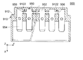
- Patent Document 1 discloses this type of connection device 900.
- the connection device 900 of Patent Document 1 includes a holding member 910 and a conductive member 950.
- the holding member 910 has a holding portion 912.
- the holding portion 912 is provided with a plurality of exposure holes 9122.
- the exposure hole 9122 penetrates a part of the holding portion 912 in the Z direction.
- the conductive member 950 includes a plurality of held parts 952, a plurality of contact parts 954, and a plurality of connecting parts 956.
- the held portion 952 is held by the holding portion 912.
- the held parts 952 are arranged in the Y direction.
- the contact portion 954 is a portion that directly contacts a counterpart terminal (not shown).
- the contact portions 954 extend from the held portion 952 in the +X direction.
- Each of the connecting portions 956 connects the held portions 952 that are adjacent to each other in the Y direction.
- the connecting portions 956 correspond to the exposed holes 9122, respectively.
- Each of the connecting portions 956 is partially exposed in the corresponding exposure hole 9122.
- the press pin 970 and the receiving jig 980 are used to set the specific connecting portion 956. Are partially removed through the corresponding exposed holes 9122.
- connection device 900 of Patent Document 1 a special tool such as the press pin 970 and the receiving jig 980 is required to remove the portion of the conductive member 950 that is desired to be made non-conductive.
- an object of the present invention is to provide a connecting device provided with a conductive member that allows a user to adjust a portion where discontinuity of conduction is to be made without using a special tool.
- One aspect of the present invention provides a connecting device including a holding member and a conductive member.
- the conductive member is held by the holding member.
- the holding member has a holding portion.
- the conductive member has a plurality of held parts, a plurality of contact parts, a plurality of extension parts, and a plurality of connecting parts.
- the held portions are held by the holding portion and are arranged in the left-right direction.
- the contact portions correspond to the held portions, respectively.
- Each of the contact portions is located in front of the corresponding held portion in the front-rear direction orthogonal to the left-right direction.
- Each of the plurality of extension portions extends rearward in the front-rear direction from any of the held portions and projects rearward of the holding portion in the front-rear direction.
- the plurality of extension portions are located apart from each other in the left-right direction.
- the plurality of connecting portions are located apart from each other in the left-right direction.
- the plurality of connecting portions are located behind the plurality of extending portions in the front-rear direction.
- Each of the connecting portions connects the two extending portions to each other.
- the two held parts that are adjacent to each other in the left-right direction are connected to the two extended parts, respectively.
- each extension portion extends rearward from any of the held portions and projects rearward of the holding portion of the holding member.
- the connecting portions are located apart from each other in the left-right direction.
- Each of the connecting parts connects the two extension parts to each other.
- the two held portions that are adjacent to each other in the left-right direction are connected to the two extended portions, respectively.
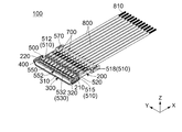
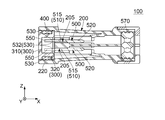
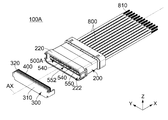
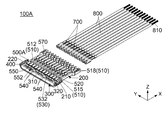
- FIG. 2 is a partially cutaway perspective sectional view showing the connection device of FIG. 1.
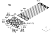
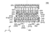
- FIG. 4 is another partially cutaway perspective sectional view showing the connection device of FIG. 3.
- the contacted part is not in contact with the contact part.
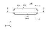
- FIG. 7 is a cross-sectional view showing the connection device of FIG. 6 taken along line AA.
- FIG. 13 is a partially cutaway perspective sectional view showing the connection device of FIG. 12. Here, a cap is attached to the surrounding portion of the holding member.
- FIG. 14 is another partially cutaway perspective sectional view showing the connection device of FIG. 13. Here, the contacted part is not in contact with the contact part.
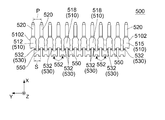
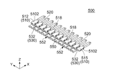
- FIG. 13 is a perspective view showing a conductive member included in the connection device of FIG. 12. It is a perspective view which shows the connection device by the 2nd Embodiment of this invention. Here, the first connector and the second connector are not connected.
- FIG. 17 is a partially cutaway perspective sectional view showing the connection device of FIG. 16.
- FIG. 17 is a perspective view showing a first connector included in the connection device of FIG. 16.
- a cap is attached to the surrounding portion of the first holding member.
- FIG. 19 is another perspective view showing the first connector of FIG. 18.
- the cap is removed from the enclosure of the first holding member.
- FIG. 22 shows the modification of the connection device of FIG.
- FIG. 22 is another cross-sectional view showing the connection device of FIG. 21.
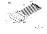
- the connection device 100 As shown in FIG. 3, the connection device 100 according to the first embodiment of the present invention includes a holding member 200, a conductive member 500, a contacted portion 700, and a plurality of cables 800.
- the conductive member 500 is held by the holding member 200.
- holding member 200 of the present embodiment is made of an insulating member.
- the holding member 200 has a plurality of accommodation holes 205 and an enclosing portion 220.
- each of the accommodation holes 205 of the present embodiment penetrates the holding member 200 in the front-back direction.
- the accommodation hole 205 is located in front of the enclosure 220 in the front-rear direction.
- the front-rear direction is the X direction.
- the front is the +X direction and the rear is the ⁇ X direction.
- the accommodation holes 205 are divided into two rows in the vertical direction.
- the vertical direction is the Z direction.
- the upper side is the +Z direction and the lower side is the ⁇ Z direction.
- the accommodation holes 205 in each row are arranged in the left-right direction.
- the left-right direction is the Y direction.
- the right side is the ⁇ Y direction and the left side is the +Y direction.
- the accommodation holes 205 are arranged so as to be rotationally symmetrical about an axis AX extending in the front-rear direction.
- each of the accommodation holes 205 of the present embodiment has a holding portion 210. That is, the holding member 200 of the present embodiment has the holding portion 210.
- the holding portion 210 of the present embodiment is the inner side surface of the accommodation hole 205 in the left-right direction.
- the holding part 210 is located near the rear end of the accommodation hole 205 in the front-rear direction.
- the holding part 210 is located in front of the enclosure part 220 in the front-rear direction.
- the enclosure 220 of the present embodiment extends in the front-rear direction.
- the enclosure 220 defines the rear end of the holding member 200.
- the rear end of the enclosure 220 is open. That is, the enclosure 220 has the opening 222 at the rear end.
- the enclosure 220 has a rotationally symmetrical shape about an axis AX extending in the front-rear direction.
- the enclosure 220 has a substantially track shape when viewed from the rear.
- the enclosure 220 has a substantially track shape that is long in the left-right direction on an orthogonal plane that is orthogonal to the front-rear direction.
- conductive member 500 of the present embodiment is made of metal.
- the conductive member 500 has a plurality of held parts 510, a plurality of contact parts 520, a plurality of extension parts 530, and a plurality of connecting parts 550.
- the held portions 510 of the present embodiment are held by the holding portions 210, respectively.
- the held parts 510 are arranged in the left-right direction. More specifically, the held portion 510 is divided into two rows in the vertical direction. The held portions 510 in each row are arranged in the left-right direction.
- the held portion 510 is arranged so as to be rotationally symmetrical about an axis AX extending in the front-rear direction.
- the held portions 510 correspond to the accommodation holes 205 of the holding member 200, respectively.
- Each of the held parts 510 is press-fitted and housed in the corresponding housing hole 205.
- the held portion 510 of the present embodiment has a press-fitting protrusion 5102 that protrudes outward in the left-right direction.
- the press-fitting protrusion 5102 is press-fitted into the holding portion 210 of the accommodation hole 205 of the holding member 200.
- the plurality of held parts 510 include a rightmost held part 515, a leftmost held part 512, and at least one normal held part 518.
- the rightmost held part 515 is located on the rightmost side of the plurality of held parts 510 in the left-right direction.
- the leftmost held portion 512 is located on the leftmost side of the plurality of held portions 510 in the left-right direction.
- the normal held portion 518 is located between the rightmost held portion 515 and the leftmost held portion 512 in the left-right direction.
- the contact portions 520 of the present embodiment are arranged at intervals of the pitch P in the left-right direction.
- the contact portions 520 correspond to the held portions 510, respectively.
- Each of the contact portions 520 is located in front of the corresponding held portion 510 in the front-rear direction orthogonal to the left-right direction.
- the contact portion 520 of the present embodiment is a so-called pin contact (male contact).
- the contact portion 520 may be a socket contact (female contact).
- each of the extension portions 530 of the present embodiment extends rearward from any of the held portions 510 in the front-rear direction and projects rearward from the holding portion 210 in the front-rear direction.
- one extension portion 530 extends rearward from the rightmost held portion 515 in the front-rear direction.
- One extension 530 extends rearward from the leftmost held portion 512 in the front-rear direction.
- Two extension parts 530 extend rearward in the front-rear direction from one normal held part 518. The plurality of extension portions 530 are located apart from each other in the left-right direction.
- a part of the extension portion 530 is surrounded by the enclosure portion 220 in an orthogonal plane orthogonal to the front-rear direction.
- the orthogonal plane is the YZ plane. More specifically, a part of the extension 530 is located inside the enclosure 220. A part of the extension portion 530 is exposed inside the enclosure 220.
- the extension portion 530 of the present embodiment is provided with a weak portion 532 having low strength. More specifically, the weakened portion 532 has the least strength in the extension portion 530. Further, the weak portion 532 has a lower strength than the held portion 510 and the connecting portion 550.
- the weak portion 532 is a groove extending in the left-right direction. The present invention is not limited to this.
- the extension part 530 may be modified as long as a part of the extension part 530 is reduced in the cross-sectional area orthogonal to the front-rear direction and functions as the weak part 532.
- the weak portion 532 of the present embodiment is surrounded by the enclosing portion 220 in the orthogonal plane. More specifically, the weak portion 532 is located within the enclosure 220. The weak portion 532 is exposed inside the enclosure 220.
- the plurality of connecting portions 550 of the present embodiment are located apart from each other in the left-right direction.
- the plurality of connecting portions 550 are located behind the plurality of extending portions 530 in the front-rear direction.
- Each of the connection parts 550 connects the two extension parts 530 to each other.
- the two held portions 510 that are adjacent to each other in the left-right direction are connected to the two extended portions 530, respectively.
- Each of the connecting portions 550 has one extended portion 530 extending from one held portion 510 of the two held portions 510 located adjacent to each other in the left-right direction and the other extending portion 530 extending from the remaining one held portion 510.
- One of the extension portions 530 is connected.
- the connecting portion 550 can be removed from the conductive member 500 by breaking it off. More specifically, the connecting portion 550 can be separated from the conductive member 500 by dividing each of the two extending portions 530 into two in the front and rear direction at the weak portion 532.
- the size S of the connecting portion 550 is smaller than the pitch P between two adjacent contact portions 520. This prevents the connecting portions 550 from contacting each other.
- the connecting portion 550 of the present embodiment is surrounded by the enclosing portion 220 in the orthogonal plane. More specifically, the connecting portion 550 is located inside the enclosure 220. The connecting portion 550 is exposed inside the enclosure 220.
- the connecting portion 550 of the present embodiment has a recessed portion 552.
- the recessed portion 552 is located at the rear end of the connecting portion 550 in the front-rear direction.
- the recessed portion 552 is a recessed portion that is open rearward and is recessed forward.
- the recessed portion 552 is a portion for hooking a tool when the connecting portion 550 is broken off.
- connection part 550 Since the connection part 550 has the recessed part 552, the user inserts a tool into the recessed part 552 of the specific connection part 550 when dividing the two extension parts 530 connected by the specific connection part 550. Can be hooked. Therefore, it is possible to prevent the user from mistakenly removing the connecting portion 550 adjacent to the specific connecting portion 550.
- the shape of the connecting portion 550 is not limited to the above. That is, the connecting portion 550 may not have the recessed portion 552, and may have a shape different from that of the connecting portion 550 of the present embodiment. Further, the connecting portion 550 can be broken off from the conductive member 500 with a general-purpose tool such as radio pliers.
- the enclosure part 220 of the present embodiment encloses the extension part 530 and the connection part 550 in a plane orthogonal to the front-rear direction. That is, the holding member 200 has the enclosing portion 220 that encloses the extension portion 530 and the connecting portion 550 in the plane orthogonal to the front-rear direction.
- contacted portion 700 is made of metal.
- the contacted portion 700 is a so-called socket contact (female contact).
- the present invention is not limited to this.
- the contact part 520 is a socket contact
- the contacted part 700 may be a pin contact (male contact).
- the contacted portion 700 is held by the holding member 200.
- the contacted part 700 is in physical and electrical contact with the contact part 520 of the conductive member 500.
- the holding member 200 of the present embodiment holds the contacted portion 700 and the contact portion 520 of the conductive member 500 together.
- the holding member 200 of the connection device 100 according to the present embodiment has a seamless structure including a part that holds the contacted part 700 and another part that holds the contact part 520. Therefore, in the connection device 100 according to the present embodiment, when the contacted portion 700 is held by a part of the holding member 200 and the contact portion 520 is held by another part of the holding member 200 that is separate from the above part. Compared with, it is superior in terms of waterproofness.
- each of the cables 800 of the present embodiment extends in the front-rear direction.
- Each of the cables 800 has a metal core wire 810. The vicinity of the rear end of the core wire 810 is physically and electrically connected to the contacted portion 700.
- connection device 100 of the present embodiment further includes a cap 300, a first seal member (seal member) 400, and a second seal member 570.
- the cap 300 of the present embodiment has a rotationally symmetrical shape about an axis AX extending in the front-rear direction.
- the cap 300 has a closed rear end and an open front end. More specifically, the cap 300 has a rear surface 310 and a tubular portion 320.
- the rear surface 310 defines the rear end of the cap 300.
- the tubular portion 320 is located in front of the rear surface 310.
- the tubular portion 320 is connected to the front end of the rear surface 310.
- the tubular portion 320 has a substantially track shape when viewed along the front-rear direction.
- the tubular portion 320 has a substantially track shape that is long in the left-right direction on an orthogonal plane that is orthogonal to the front-rear direction.
- the cap 300 is attached to the enclosure 220.
- the cap 300 is located at the rear end of the connection device 100 in the front-rear direction.
- the cap 300 closes the opening 222 (see FIG. 2) of the enclosure 220.
- a part of the extension portion 530 is enclosed by the tubular portion 320 in the orthogonal plane. More specifically, in the attached state, a part of the extension portion 530 is located inside the tubular portion 320. In the attached state, a part of the extension portion 530 is exposed inside the tubular portion 320.
- the connecting portion 550 is surrounded by the tubular portion 320 in the orthogonal plane in the attached state where the cap 300 is attached to the enclosing portion 220. More specifically, in the attached state, the connecting portion 550 is located inside the tubular portion 320. In the attached state, the connecting portion 550 is exposed inside the tubular portion 320.
- the first seal member 400 of the present embodiment is made of an elastic insulator such as rubber.
- the first seal member 400 has a substantially track shape when viewed along the front-rear direction.
- the first seal member 400 has a substantially track shape that is long in the left-right direction on an orthogonal plane that is orthogonal to the front-rear direction.
- the first seal member 400 is located in front of the rear surface 310 of the cap 300 in the front-rear direction.
- the first seal member 400 is located outside the tubular portion 320 of the cap 300 in the orthogonal direction orthogonal to the front-rear direction.
- the first seal member 400 surrounds the tubular portion 320 of the cap 300 in the orthogonal plane.
- the first seal member 400 is in close contact with the tubular portion 320 in the orthogonal direction.
- the first seal member 400 In the attached state in which the cap 300 is attached to the enclosing portion 220, the first seal member 400 is located behind the held portion 510 of the conductive member 500 in the front-rear direction. In the attached state, the first seal member 400 is located behind the weak portion 532 in the front-rear direction. In the attached state, the first seal member 400 is located inside the enclosing portion 220 in the orthogonal direction. In the attached state, the first seal member 400 is in close contact with the enclosing portion 220 in the orthogonal direction.
- the first seal member 400 is interposed between the cap 300 and the enclosing portion 220. That is, the first seal member 400 seals the gap between the cap 300 and the enclosure 220 with water.
- second sealing member 570 of the present embodiment is made of an elastic insulator such as rubber.
- the second seal member 570 is located near the front end of the holding member 200 in the front-rear direction.
- the second seal member 570 is located in front of the contacted portion 700 in the front-rear direction.
- the second seal member 570 is in close contact with the holding member 200 in the orthogonal direction.
- the second seal member 570 is in close contact with the cable 800 in the orthogonal direction.
- the second seal member 570 is interposed between the holding member 200 and the cable 800 and between the cables 800. That is, the second seal member 570 seals water between the holding member 200 and the cable 800 and between the cables 800.
- the conductive portion including the contacted portion 700 and the conductive member 500 is the holding member 200 and the cap 300. It is sealed with water from the outside.
- the structure of the conductive member 500 is not limited to that described above.
- the conductive member 500 can be modified as follows.
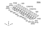
- the conductive member 500A of the connection device 100A of the present modified example has a plurality of held parts 510, a plurality of contact parts 520, a plurality of extension parts 530, and a plurality of extension part remaining parts. It has 540 and the some connection part 550.
- the present invention is not limited to this. As long as the conductive member 500A has a plurality of held parts 510, a plurality of contact parts 520, a plurality of extension parts 530, two remaining extension parts 540, and a plurality of coupling parts 550, the conductive member. 500A may be modified.
- each of the two extension parts 530 connected by the connection part 550 is separated into two in the front-rear direction, so that at least one connection part 550 and a part of the two extension parts 530 are removed.
- the connecting portion 550 may be modified.
- the conductive member 500A of this modification can be implemented by breaking off at least one connecting portion 550 from the conductive member 500A in the state of FIG. 2 in which the cap 300 is removed from the enclosing portion 220. Therefore, in the conductive member 500A, before the cable 800 is connected to the conductive member 500A via the contacted portion 700, the contact portions 520 can be set to have arbitrary conduction combinations. Similarly, in the conductive member 500A, even after the cable 800 is connected to the conductive member 500A through the contacted portion 700, the contact portions 520 can be in any combination of conduction.
- the held portion 510 of this modification is divided into a plurality of groups including at least a first group G1 and a second group G2 in the left-right direction. That is, the conductive member 500A of the present modified example has at least the held portion 510 included in the first group G1 and the held portion 510 included in the second group G2. More specifically, the held portion 510 is divided into three groups in the left-right direction, that is, a first group G1, a second group G2, and a third group G3.
- the first group G1 and the second group G2 are adjacent to each other in the left-right direction. More specifically, the first group G1 is adjacent to the left side of the second group G2 in the left-right direction. Further, the second group G2 and the third group G3 are adjacent to each other in the left-right direction. More specifically, the second group G2 is adjacent to the left side of the third group G3 in the left-right direction.
- the extension remaining portion 540 of the present modification is generated by breaking the connecting portion 550 from the conductive member 500 with a tool. Further, the extension remaining portion 540 of the present modified example is generated from the extension 530 that is connected to the removed connecting portion 550. That is, each of the extension remaining portions 540 is one of the two extension 530 separated in the front-rear direction. Therefore, each of the extension remaining portions 540 is shorter than the extension 530 in the front-rear direction.
- the rear end of the extension remaining portion 540 is a division mark generated when the extension 530 is divided in the weak portion 532 in the front-rear direction by a tool.
- the first group G1 includes one extension remaining portion 540.
- the extension remaining portion 540 of the first group G1 extends rearward in the front-rear direction from the held portion 510 closest to the second group G2 among the held portions 510 of the first group G1.
- the second group G2 includes two extension remaining portions 540.
- One extension remaining portion 540 of the second group G2 extends rearward in the front-rear direction from the held portion 510 closest to the first group G1 among the held portions 510 of the second group G2.
- the remaining one extension remaining portion 540 of the second group G2 extends rearward in the front-rear direction from the held portion 510 closest to the third group G3 among the held portions 510 of the second group G2.
- the third group G3 includes one extension remainder 540.
- the extension remaining portion 540 of the third group G3 extends rearward in the front-rear direction from the held portion 510 closest to the second group G2 among the held portions 510 of the third group G3.
- the present invention is not limited to this.
- the conductive member 500A may be modified as long as the conductive member 500A has the following configuration.
- the conductive member 500A includes two extension remaining portions 540.
- the held portion 510 is divided in the left-right direction into two groups, a first group G1 and a second group G2.
- One extension remaining portion 540 extends rearward in the front-rear direction from the held portion 510 closest to the second group G2 among the held portions 510 of the first group G1.
- the remaining one extension remaining portion 540 extends rearward in the front-rear direction from the held portion 510 closest to the first group G1 among the held portions 510 of the second group G2.
- the rear end of the extension remaining portion 540 of this modification is surrounded by the enclosure 220 in the orthogonal plane. More specifically, the rear end of the extension remaining portion 540 is located inside the enclosure 220. The rear end of the extension remaining portion 540 is exposed inside the enclosure 220.
- the rear end of the extension remaining portion 540 of the present modification is attached to the tubular portion 320 in the orthogonal plane. being surrounded. More specifically, in the attached state, the rear end of the extension remaining portion 540 is located inside the tubular portion 320. In the attached state, the rear end of the extension remaining portion 540 is exposed inside the tubular portion 320.
- each of the connection parts 550 connects the two extension parts 530 to each other.
- the two held portions 510 that are adjacent to each other in the left-right direction are connected to the two extended portions 530, respectively.
- the held portions 510 included in the first group G1 are electrically connected to each other by the extension portion 530 and the connecting portion 550.
- the held parts 510 included in the second group G2 are electrically connected to each other by the extension part 530 and the connection part 550.
- the held parts 510 included in the third group G3 are electrically connected to each other by the extension part 530 and the connection part 550.
- each of the held parts 510 included in the first group G1 is not electrically connected to any of the held parts 510 included in the second group G2.
- Each of the held parts 510 included in the first group G1 is not electrically connected to any of the held parts 510 included in the third group G3.
- Each of the held parts 510 included in the second group G2 is not electrically connected to any of the held parts 510 included in the third group G3.
- the conducting portion including the contacted portion 700 and the conductive member 500A is the holding member 200 and the cap 300. It is sealed with water from the outside.
- the connection device 900 of Patent Document 1 has a problem that the trace of the conductive member 950 caused by the removal of the connecting portion 956 is exposed in the exposure hole 9122. On the other hand, in the connection device 100A of this modification, such a problem does not occur. Therefore, the conductive portion, particularly the remaining portion 540 of the extended portion is prevented from coming into contact with water droplets.
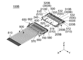
- the connecting device 100B As shown in FIG. 16, the connecting device 100B according to the second embodiment of the present invention has a first connector 600 and a second connector 650.
- first connector 600 As shown in FIG. 16, the connecting device 100B according to the second embodiment of the present invention has a first connector 600 and a second connector 650.
- second connector 650 As for the azimuth and direction in the present embodiment, the same expressions as in the first embodiment will be used below.
- the first connector 600 of the present embodiment includes a first holding member (holding member) 200B and a conductive member 500.
- the conductive member 500 is held by the first holding member 200B. That is, the connection device 100B includes the first holding member (holding member) 200B and the conductive member 500 held by the first holding member 200B.
- first holding member 200B of the present embodiment is made of an insulating member.
- the first holding member 200B has a plurality of accommodation holes 205B, an enclosing portion 220B, and a fitting portion 240.
- each of the accommodation holes 205B of the present embodiment penetrates the first holding member 200B in the front-rear direction.
- the accommodation hole 205B is located in front of the enclosure 220B in the front-rear direction. More specifically, the accommodation holes 205B are divided into two rows in the vertical direction. The accommodation holes 205B in each row are arranged in the left-right direction.
- the accommodation hole 205B is arranged so as to be rotationally symmetrical about an axis BX (see FIG. 18) extending in the front-rear direction.
- each of the accommodation holes 205B of this embodiment has a first holding portion (holding portion) 210B. That is, the first holding member (holding member) 200B of the present embodiment has the holding portion 210B.
- the first holding portion 210B of the present embodiment is the inner side surface of the accommodation hole 205B in the left-right direction.
- the first holding portion 210B is located in front of the enclosing portion 220B in the front-rear direction.
- the enclosure 220B of the present embodiment extends in the front-rear direction.
- the enclosure 220B defines the rear end of the first holding member 200B.
- the rear end of the enclosure 220B is open. That is, the enclosure 220B has the opening 222B at the rear end.
- the enclosure 220B has a rotationally symmetrical shape about an axis BX extending in the front-rear direction.
- the enclosure 220B has a substantially track shape when viewed from the rear.
- the enclosure 220B has a substantially track shape that is long in the left-right direction on an orthogonal plane that is orthogonal to the front-rear direction.
- the fitting portion 240 of this embodiment is located in front of the accommodation hole 205B in the front-rear direction.
- the front end of the fitting portion 240 is open.
- the contact portion 520 of the conductive member 500 is surrounded by the fitting portion 240 in the orthogonal plane.
- the front end of the fitting portion 240 is located in front of the front end of the contact portion 520 of the conductive member 500 in the front-rear direction.
- the fitting part 240 has a contacted part accommodation part 242.
- the contacted part accommodation part 242 of the present embodiment is a space extending in the front-rear direction.
- the contacted portion accommodation portion 242 communicates with the accommodation hole 205B in the front-rear direction.
- the contact portion 520 of the conductive member 500 is located inside the contacted portion accommodation portion 242. The contact portion 520 is exposed in the contacted portion accommodation portion 242.
- the conductive member 500 has a plurality of held parts 510, a plurality of contact parts 520, a plurality of extension parts 530, and a plurality of connecting parts 550. There is.
- the configuration of the conductive member 500 of the present embodiment is similar to that of the conductive member 500 of the first embodiment. Therefore, details are omitted.
- a part of the extension part 530 of the present embodiment is surrounded by the enclosing part 220B in the orthogonal plane. More specifically, a part of the extension portion 530 is located inside the enclosing portion 220B. A part of the extension portion 530 is exposed inside the enclosing portion 220B.
- the weak portion 532 of the present embodiment is surrounded by the enclosing portion 220B in the orthogonal plane. More specifically, the weak portion 532 is located inside the enclosing portion 220B. The weak portion 532 is exposed in the enclosing portion 220B.
- the connecting portion 550 of the present embodiment is surrounded by the enclosing portion 220B in the orthogonal plane. More specifically, the connecting portion 550 is located inside the enclosing portion 220B. The connecting portion 550 is exposed in the enclosing portion 220B.
- the first connector 600 of the present embodiment further includes a cap 300B and a first seal member (seal member) 400B.
- the cap 300B of the present embodiment has a rotationally symmetrical shape about an axis BX extending in the front-rear direction.
- the cap 300B has a closed rear end and an open front end. More specifically, the cap 300B has a rear surface 310B and a tubular portion 320B.
- the rear surface 310B defines the rear end of the cap 300B.
- the tubular portion 320B is located in front of the rear surface 310B.
- the tubular portion 320B is connected to the front end of the rear surface 310B.
- the tubular portion 320B has a substantially track shape when viewed along the front-rear direction.
- the cylindrical portion 320B has a substantially track shape that is long in the left-right direction on an orthogonal plane that is orthogonal to the front-rear direction.
- the cap 300B is located at the rear end of the first connector 600 in the front-rear direction.
- the cap 300B is attached to the enclosure 220B.
- the cap 300B closes the opening 222B (see FIG. 19) of the enclosure 220B.
- part of the extension portion 530 is enclosed by the tubular portion 320B in the orthogonal plane. More specifically, in the attached state, a part of the extension portion 530 is located inside the tubular portion 320B. In the attached state, part of the extension portion 530 is exposed inside the tubular portion 320B.
- the weak portion 532 is enclosed by the tubular portion 320B in the orthogonal plane. More specifically, in the attached state, the weak portion 532 is located inside the tubular portion 320B. In the attached state, the weak portion 532 is exposed in the tubular portion 320B.
- the connecting portion 550 is enclosed by the tubular portion 320B in the orthogonal plane. More specifically, in the attached state, the connecting portion 550 is located inside the tubular portion 320B. In the attached state, the connecting portion 550 is exposed inside the tubular portion 320B.
- first seal member 400B of the present embodiment is made of an elastic insulator such as rubber.
- the first seal member 400B has a substantially track shape when viewed along the front-rear direction.
- the first seal member 400B has a substantially track shape that is long in the left-right direction on an orthogonal plane that is orthogonal to the front-rear direction.
- the first seal member 400B is located in front of the rear surface 310B of the cap 300B in the front-rear direction.
- the first seal member 400B is located outside the tubular portion 320B of the cap 300B in the orthogonal direction.
- the first seal member 400B surrounds the tubular portion 320B of the cap 300B in the orthogonal plane.
- the first seal member 400B is in close contact with the tubular portion 320B in the orthogonal direction.
- the first seal member 400B In the attached state in which the cap 300B is attached to the enclosing portion 220B, the first seal member 400B is located behind the held portion 510 of the conductive member 500 in the front-rear direction. In the attached state, the first seal member 400B is located behind the weak portion 532 in the front-rear direction. In the attached state, the first seal member 400B is located inside the enclosing portion 220B in the orthogonal direction. In the attached state, the first seal member 400B is in close contact with the enclosing portion 220B in the orthogonal direction. That is, the first seal member (seal member) 400B is interposed between the cap 300B and the enclosing portion 220B. The first seal member 400B seals water between the cap 300B and the enclosure 220B.
- connection device 100B of the present embodiment further includes a cap 300B attached to the enclosure 220B and a first seal member (seal member) 400B interposed between the cap 300B and the enclosure 220B.
- the second connector 650 of the present embodiment includes a second holding member 660, a second seal member 570, a third seal member 580, a contacted portion 700, and a cable 800. I have it. Of these, the second seal member 570, the contacted portion 700, and the cable 800 are the same as those in the first embodiment. Therefore, details are omitted.
- the second holding member 660 of this embodiment is separate from the first holding member 200B of the first connector 600.
- the second holding member 660 holds the contacted portion 700 and the cable 800.
- the second holding member 660 has a fitted portion 662.
- the fitted portion 662 of the present embodiment is located at the rear end of the second holding member 660 in the front-rear direction.
- the fitted part 662 has a substantially track shape when viewed along the front-rear direction.
- the fitted portion 662 has a substantially track shape that is long in the left-right direction on an orthogonal plane orthogonal to the front-rear direction.
- the fitted portion 662 surrounds the contacted portion 700 in the orthogonal plane.
- the rear end of the fitted portion 662 is located rearward of the rear end of the contacted portion 700 in the front-rear direction.
- third seal member 580 of the present embodiment is made of an elastic insulator such as rubber.
- the third seal member 580 has a substantially track shape when viewed along the front-rear direction.
- the third seal member 580 has a substantially track shape that is long in the left-right direction on an orthogonal plane that is orthogonal to the front-rear direction.
- the third seal member 580 is located behind the cable 800 in the front-rear direction.
- the third seal member 580 is located in front of the rear end of the fitted portion 662 in the front-rear direction.
- the third seal member 580 is located outside the fitted portion 662 in the orthogonal direction.
- the third seal member 580 surrounds the fitted portion 662 in the orthogonal plane.
- the third seal member 580 is in close contact with the fitted portion 662 in the orthogonal direction.
- the third seal member 580 is positioned inside the fitting portion 240 in the orthogonal direction in the fitted state where the first connector 600 and the second connector 650 are fitted to each other. doing.
- the third seal member 580 is in close contact with the fitting portion 240 in the orthogonal direction.
- the third seal member 580 is interposed between the fitting portion 240 and the fitted portion 662. That is, in the fitted state, the third seal member 580 seals water between the fitting portion 240 and the fitted portion 662.
- the structure of the conductive member 500 is not limited to that described above.
- the conductive member 500 can be modified as follows.
- a conductive member (not shown) of the connection device (not shown) of the present modification has a plurality of held parts 510, a plurality of contact parts 520, a plurality of extension parts 530, It has a plurality of extension remaining portions 540 and a plurality of connecting portions 550. That is, in the conductive member of the present modification, each of the two extension portions 530 is separated into two in the front-rear direction, so that at least one connecting portion 550 and a part of the two extension portions 530 are removed. ing.
- the present invention is not limited to this.
- the conductive member has a plurality of held parts 510, a plurality of contact parts 520, a plurality of extension parts 530, two remaining extension parts 540, and a plurality of connection parts 550, the conductive member is It may be modified.
- the conductive member of this modification is the same as the conductive member 500A of the modification of the first embodiment. Therefore, details are omitted.
- the rear end of the extension remaining portion 540 of the present modification is surrounded by the enclosing portion 220B in the orthogonal plane. More specifically, the rear end of the extension remaining portion 540 is located inside the enclosure 220B. The rear end of the extension remaining portion 540 is exposed inside the enclosure 220B.
- the rear end of the extension remaining portion 540 of the present modification is enclosed by the tubular portion 320B in the orthogonal plane. More specifically, in the attached state, the rear end of the extension remaining portion 540 is located inside the tubular portion 320B. In the attached state, the rear end of the extension remaining portion 540 is exposed in the tubular portion 320B.
- connection device of the present modification when the second connector 650 is fitted to the first connector 600 attached to the enclosing portion 220B of the cap 300B, the contacted portion is A conductive portion including 700 and a conductive member is water-sealed from the outside of the first connector 600, the second connector 650 and the cap 300B.
- the connection device 900 of Patent Document 1 has a problem that the trace of the conductive member 950 caused by the removal of the connecting portion 956 is exposed in the exposure hole 9122. On the other hand, such a problem does not occur even in the connecting device of the present modification. Therefore, the conductive portion, particularly the remaining portion 540 of the extended portion is prevented from coming into contact with water droplets.
- connection device 100B The structure of the connection device 100B is not limited to that described above.
- the connection device 100B may be modified as follows.
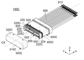
- connection device 100C of the present modified example includes a holding member 200C, a cap 300C, a first seal member (seal member) 400C, a second seal member 570, a conductive member 500, and a contacted member.
- the unit 700 and a plurality of cables 800 are provided.
- the second seal member 570, the conductive member 500, the contacted portion 700, and the cable 800 of this modification are the same as those in the above-described embodiment. Therefore, details are omitted.
- the holding member 200C of the present modification is made of an insulating member.
- the holding member 200C has a plurality of accommodation holes 205C, an enclosure 220C, and a partition 250.
- the accommodation hole 205C of this modified example is similar to the accommodation hole 205 of the first embodiment. Therefore, details are omitted.
- the enclosure 220C of this modification extends in the front-rear direction.
- the enclosure 220C defines the rear end of the holding member 200C.
- the rear end of the enclosure 220C is open. That is, the enclosure 220C has the opening 222C at the rear end.
- the enclosing portion 220C has a rotationally symmetrical shape about an axis CX extending in the front-rear direction.
- the enclosure 220C of the present modification has two side portions 224 and two cutout portions 225.
- the upper end of the side portion 224 of this modification is curved inward in the left-right direction.
- the lower end of the side portion 224 is curved inward in the left-right direction.
- the two side portions 224 are respectively located at both ends in the left-right direction of the holding member 200C.
- the side portion 224 defines the rear end of the holding member 200C in the front-rear direction.
- the rear end of each of the side portions 224 is located rearward of the rear end of the connecting portion 550 in the front-rear direction.
- the connecting portion 550 of the conductive member 500 is blocked by the side portion 224 from the right side and is not visible. Further, in the state where the cap 300C is not attached to the enclosing portion 220C, the connecting portion 550 of the conductive member 500 is blocked by the side portion 224 from the left side and is not visible. As a result, in the state where the cap 300C is not attached to the enclosing portion 220C, the connecting portion 550 of the conductive member 500 is prevented from being inadvertently hit by the tool from the left and right directions.
- each of the cutout portions 225 of this modified example is recessed forward in the front-rear direction.
- the two cutout portions 225 are located at both ends in the vertical direction of the enclosing portion 220C.
- Each of the cutout portions 225 is located between the two side portions 224 in the left-right direction.
- the connecting portion 550 of the conductive member 500 is visible through the cutout portion 225. That is, in the state where the cap 300C is not attached to the enclosing portion 220C, the connecting portion 550 of the conductive member 500 is visible along the vertical direction through the cutout portion 225.
- the connecting portion 550 of the conductive member 500 is visible from above through the cutout portion 225.
- the connecting portion 550 of the conductive member 500 is visible from below through the cutout portion 225 when the cap 300C is not attached to the enclosing portion 220C. This allows the user to hook the tool on the recess 552 from the outer side in the vertical direction when breaking off the connecting portion 550.
- the partition part 250 of this modification has a flat plate shape orthogonal to the vertical direction.
- the partition part 250 defines the rear end of the holding member 200C in the front-rear direction.
- the rear end of the partition part 250 is located rearward of the rear end of the connecting part 550 in the front-rear direction.
- the partition part 250 is located between the two side parts 224 in the left-right direction.
- the two side parts 224 are located at both ends of the partition part 250 in the left-right direction.
- the two side portions 224 are connected to the left and right ends of the partition portion 250, respectively. That is, the partition part 250 is reinforced by the two side parts 224, and the vertical bending is prevented.
- the partition part 250 is located between the two rows of the accommodation holes 205C in the vertical direction.
- the partition part 250 is located between two rows of the held parts 510 in the vertical direction.
- the partition part 250 includes, in the vertical direction, a connecting part 550 that is connected to the held parts 510 in the upper two rows and the held parts 510 in the lower two rows and the extended parts 530. It is located between the connection part 550 connected via 530. Accordingly, when the user breaks the connecting portion 550, which is connected to the held portion 510 in the upper row through the extension portion 530, using the tool, the held portion 510 and the extension portion 530 in the lower row. It is avoided that the user accidentally brings the tool into contact with the connecting portion 550 connected via the.
- the cap 300C of this modification has a rotationally symmetrical shape about an axis CX extending in the front-rear direction.
- the cap 300C has a closed rear end and an open front end. More specifically, the cap 300C has a rear surface 310C and a tubular portion 320C.
- the rear surface 310C defines the rear end of the cap 300C.
- the cylindrical portion 320C is located in front of the rear surface 310C.
- the cylindrical portion 320C is connected to the front end of the rear surface 310C.
- the tubular portion 320C has a substantially track shape when viewed along the front-rear direction.
- the cylindrical portion 320C has a substantially track shape that is long in the left-right direction on an orthogonal plane that is orthogonal to the front-rear direction.
- the cap 300C of this modification is attached to the enclosure 220C.
- the cap 300C In the attached state where the cap 300C is attached to the enclosing portion 220C, the cap 300C is located at the rear end of the connection device 100C in the front-rear direction. In the attached state, the cap 300C closes the opening 222C of the enclosure 220C.
- the rear ends of the side part 224 and the partition part 250 are located rearward of the rear end of the connecting part 550 in the front-rear direction.
- the rear ends of the side portions 224 and the partition 250 abut the rear surface 310C of the cap 300C before the rear end of the connecting portion 550 abuts the rear surface 310C of the cap 300C. That is, the side part 224 and the partition part 250 prevent the rear end of the coupling part 550 from hitting the rear surface 310C of the cap 300C when the cap 300C is attached to the enclosing part 220C.
- a part of the extension portion 530 faces a part of the tubular portion 320C through the cutout portion 225 in the vertical direction.
- the connecting portion 550 faces a part of the tubular portion 320C through the cutout portion 225 in the vertical direction.
- the first seal member (seal member) 400C of this modification is made of an elastic insulator such as rubber.
- the first seal member 400C has a substantially track shape when viewed in the front-rear direction.
- the first seal member 400C has a substantially track shape that is long in the left-right direction on an orthogonal plane orthogonal to the front-rear direction.
- the first seal member 400C is located in front of the connecting portion 550 in the front-rear direction.
- the first seal member 400C is in close contact with the enclosing portion 220C in the orthogonal direction.
- the first seal member 400C is located in front of the rear surface 310C of the cap 300C in the front-rear direction.
- the first seal member 400C is located inside the tubular portion 320C of the cap 300C in the orthogonal direction orthogonal to the front-rear direction. In the attached state, the first seal member 400C is surrounded by the tubular portion 320C of the cap 300C in the orthogonal plane. In the attached state, the first seal member 400C is in close contact with the tubular portion 320C in the orthogonal direction. In the attached state, the first seal member 400C is interposed between the cap 300C and the enclosing portion 220C.
- the first seal member 400C seals the gap between the cap 300C and the enclosing portion 220C with water.
- the conductive portion including the contacted portion 700 and the conductive member 500 is water-sealed from the outside of the holding member 200C and the cap 300C.
- the structure of the conductive member 500 is not limited to that described above.
- the conductive member 500 can be modified as follows.
- a conductive member (not shown) of the connection device (not shown) of the present modification has a plurality of held parts 510, a plurality of contact parts 520, a plurality of extension parts 530, It has a plurality of extension remaining portions 540 and a plurality of connecting portions 550. That is, in the conductive member of the present modification, each of the two extension portions 530 is separated into two in the front-rear direction, so that at least one connecting portion 550 and a part of the two extension portions 530 are removed. ing.
- the present invention is not limited to this.
- the conductive member has a plurality of held parts 510, a plurality of contact parts 520, a plurality of extension parts 530, two remaining extension parts 540, and a plurality of connection parts 550, the conductive member is It may be modified.
- the conductive member of this modification is the same as the conductive member 500A of the modification of the first embodiment. Therefore, details are omitted.
- connection device of the present modification when the cap 300C is attached to the enclosing portion 220C, the conductive portion including the contacted portion 700 and the conductive member is the holding member 200C. Also, the cap 300C is water-sealed from outside.
- the connection device 900 of Patent Document 1 has a problem that the trace of the conductive member 950 caused by the removal of the connecting portion 956 is exposed in the exposure hole 9122. On the other hand, such a problem does not occur even in the connecting device of the present modification. Therefore, the conductive portion, particularly the remaining portion 540 of the extended portion is prevented from coming into contact with water droplets.
- the first seal members 400, 400B are provided outside the tubular portions 320, 320B of the caps 300, 300B in the orthogonal direction, but the present invention is not limited to this. Not limited to. That is, the first seal members 400 and 400B may be provided inside the tubular portions 320 and 320B of the caps 300 and 300B in the orthogonal direction. Even when the first seal members 400 and 400B are provided on the tubular portions 320 and 320B of the caps 300 and 300B as described above, when the caps 300 and 300B are attached to the enclosing portions 220 and 220B, the first seal members are attached.
- the first sealing members 400 and 400B can secure the space between the caps 300 and 300B and the enclosing portions 220 and 220B. Can be water sealed.
- the present invention is based on Japanese Patent Application No. 2018-244577 filed with the Japan Patent Office on December 27, 2018, the contents of which are incorporated herein by reference.
Landscapes
- Connector Housings Or Holding Contact Members (AREA)
Abstract
接続装置は、保持部材と、導電部材とを備えている。保持部材は、保持部を有している。導電部材は、複数の被保持部と、複数の接触部と、複数の延長部と、複数の連結部とを有している。複数の延長部の夫々は、いずれかの被保持部から前後方向において後方に延びて、前後方向において保持部より後方に突出している。複数の延長部は、左右方向において互いに離れて位置している。複数の連結部は、左右方向において、互いに離れて位置している。複数の連結部は、前後方向において、複数の延長部の後方に位置している。連結部の夫々は、2つの延長部を互いに連結している。左右方向において隣り合う2つの被保持部は、2つの延長部と夫々連結されている。
Description
本発明は、複数の相手側端子のうち所定のもの同士を導通させるために用いられる接続装置に関する。
特許文献1は、この種の接続装置900を開示している。図21及び図22を参照すると、特許文献1の接続装置900は、保持部材910と導電部材950とを備えている。保持部材910は、保持部912を有している。保持部912には、複数の露出孔9122が設けられている。露出孔9122は、保持部912の一部をZ方向において貫通している。導電部材950は、複数の被保持部952と、複数の接触部954と、複数の連結部956とを有している。被保持部952は、保持部912に保持されている。被保持部952は、Y方向に並んでいる。接触部954は、相手側端子(図示せず)と直接接触する部分である。接触部954は、被保持部952から+X方向に夫々延びている。連結部956の夫々は、Y方向において隣り合う被保持部952同士を連結している。連結部956は、露出孔9122と夫々対応している。連結部956の夫々は、対応する露出孔9122内に部分的に露出している。連結部956のうち特定の一部を導通不能として相手側端子(図示せず)のうち所定のもの同士を導通させるためには、プレスピン970と受け冶具980を用いて、特定の連結部956をそれに対応する露出孔9122を通して部分的に除去する。
特許文献1の接続装置900においては、導電部材950のうちの導通不能にしたい部分を除去するためにプレスピン970と受け冶具980のような特殊な工具が必要である。
そこで、本発明は、特殊な工具を用いることなく、導通不能にしたい箇所を使用者が調整可能な導電部材を備える接続装置を提供することを目的とする。
本発明の一の側面は、保持部材と、導電部材とを備える接続装置を提供する。前記導電部材は、前記保持部材に保持されている。前記保持部材は、保持部を有している。前記導電部材は、複数の被保持部と、複数の接触部と、複数の延長部と、複数の連結部とを有している。前記被保持部は、前記保持部に保持されており、且つ、左右方向に並んでいる。前記接触部は、前記被保持部に夫々対応している。前記接触部の夫々は、前記左右方向と直交する前後方向において前記対応する被保持部の前方に位置している。前記複数の延長部の夫々は、いずれかの前記被保持部から前記前後方向において後方に延びて、前記前後方向において前記保持部より後方に突出している。前記複数の延長部は、前記左右方向において互いに離れて位置している。前記複数の連結部は、前記左右方向において互いに離れて位置している。前記複数の連結部は、前記前後方向において、前記複数の延長部の後方に位置している。前記連結部の夫々は、2つの前記延長部を互いに連結している。前記左右方向において隣り合う2つの前記被保持部は、前記2つの延長部と夫々連結されている。
本発明の接続装置においては、各延長部がいずれかの被保持部から後方に延びて保持部材の保持部よりも後方に突出している。また、連結部は互いに左右方向に離れて位置している。連結部の夫々は、2つの延長部を互いに連結している。左右方向において隣り合う2つの被保持部は、2つの延長部と夫々連結されている。使用者が特定の連結部を除去しようとする場合、使用者は、特定の連結部によって連結されている延長部の夫々を前後方向に2つに分離する。これにより、使用者は、特定の連結部を選択的に除去することが可能である。また、その際、使用者は、延長部を直接的に切断したり、連結部に負荷を加えて連結されている延長部を折り取ったりすることができる。この延長部の切断や折り取りは、一般的な工具を用いて、比較的容易に行うことができる。
添付の図面を参照しながら下記の最良の実施の形態の説明を検討することにより、本発明の目的が正しく理解され、且つその構成についてより完全に理解されるであろう。
本発明については多様な変形や様々な形態にて実現することが可能であるが、その一例として、図面に示すような特定の実施の形態について、以下に詳細に説明する。図面及び実施の形態は、本発明をここに開示した特定の形態に限定するものではなく、添付の請求の範囲に明示されている範囲内においてなされる全ての変形例、均等物、代替例をその対象に含むものとする。
(第1の実施の形態)
図3に示されるように、本発明の第1の実施の形態による接続装置100は、保持部材200と、導電部材500と、被接触部700と、複数のケーブル800とを備えている。導電部材500は、保持部材200に保持されている。
図3に示されるように、本発明の第1の実施の形態による接続装置100は、保持部材200と、導電部材500と、被接触部700と、複数のケーブル800とを備えている。導電部材500は、保持部材200に保持されている。
図4を参照して、本実施の形態の保持部材200は、絶縁部材からなる。保持部材200は、複数の収容孔205と、囲い部220とを有している。
図7及び図8に示されるように、本実施の形態の収容孔205の夫々は、前後方向において保持部材200を貫通している。収容孔205は、前後方向において囲い部220の前方に位置している。本実施の形態において、前後方向はX方向である。ここで、前方を+X方向とし、後方を-X方向とする。より詳しくは、収容孔205は、上下方向において2列に分けられている。本実施の形態において、上下方向はZ方向である。ここで、上方を+Z方向とし、下方を-Z方向とする。各列の収容孔205は、左右方向に並べられている。本実施の形態において、左右方向は、Y方向である。ここで、右方を-Y方向とし、左方を+Y方向とする。収容孔205は、前後方向に延びる軸AXを中心として回転対称となるように配置されている。
図8に示されるように、本実施の形態の収容孔205の夫々は、保持部210を有している。即ち、本実施の形態の保持部材200は、保持部210を有している。
図8に示されるように、本実施の形態の保持部210は、収容孔205の左右方向における両内側面である。保持部210は、前後方向において収容孔205の後端付近に位置している。保持部210は、前後方向において囲い部220の前方に位置している。
図2、図7及び図8から理解されるように、本実施の形態の囲い部220は、前後方向に延びている。囲い部220は、保持部材200の後端を規定している。囲い部220の後端は、開口している。即ち、囲い部220は、後端に開口部222を有している。囲い部220は、前後方向に延びる軸AXを中心として回転対称な形状を有している。囲い部220は、後方から見た場合、略トラック形状を有している。囲い部220は、前後方向と直交する直交平面において、左右方向に長い略トラック形状を有している。
図3及び図9を参照して、本実施の形態の導電部材500は、金属製である。導電部材500は、複数の被保持部510と、複数の接触部520と、複数の延長部530と、複数の連結部550とを有している。
図3及び図8に示されるように、本実施の形態の被保持部510は、保持部210に夫々保持されている。被保持部510は、左右方向に並んでいる。より詳しくは、被保持部510は、上下方向において2列に分けられている。各列の被保持部510は、左右方向に並べられている。被保持部510は、前後方向に延びる軸AXを中心として回転対称となるように配置されている。被保持部510は、保持部材200の収容孔205と夫々対応している。被保持部510の夫々は、対応する収容孔205に圧入されて収容されている。
図8に示されるように、本実施の形態の被保持部510は、左右方向外側に突出した圧入突起5102を有している。圧入突起5102は、保持部材200の収容孔205の保持部210に圧入されている。
図3及び図8に示されるように、複数の被保持部510は、最右被保持部515と、最左被保持部512と、少なくとも1つのノーマル被保持部518とを含んでいる。最右被保持部515は、左右方向において複数の被保持部510の最も右側に位置している。最左被保持部512は、左右方向において複数の被保持部510の最も左側に位置している。ノーマル被保持部518は、左右方向において最右被保持部515と最左被保持部512との間に位置している。
図9に示されるように、本実施の形態の接触部520は、左右方向においてピッチPの間隔で並べられている。接触部520は、被保持部510に夫々対応している。接触部520の夫々は、左右方向と直交する前後方向において対応する被保持部510の前方に位置している。本実施の形態の接触部520は、所謂ピンコンタクト(雄コンタクト)である。しかしながら、本発明はこれに限定されない。接触部520は、ソケットコンタクト(雌コンタクト)であってもよい。
図9に示されるように、本実施の形態の延長部530の夫々は、いずれかの被保持部510から前後方向において後方に延びて、前後方向において保持部210より後方に突出している。具体的には、最右被保持部515からは、1つの延長部530が前後方向において後方に延びている。最左被保持部512からは、1つの延長部530が前後方向において後方に延びている。1つのノーマル被保持部518からは、2つの延長部530が前後方向において後方に延びている。複数の延長部530は、左右方向において互いに離れて位置している。
図7及び図8から理解されるように、延長部530の一部は、前後方向と直交する直交面内において囲い部220に囲まれている。本実施の形態において、直交面はYZ平面である。より詳しくは、延長部530の一部は、囲い部220内に位置している。延長部530の一部は、囲い部220内において露出している。
図9に示されるように、本実施の形態の延長部530には、強度の弱い弱部532が設けられている。より詳しくは、弱部532は、延長部530の中で強度が最小である。また、弱部532は、被保持部510や連結部550よりも強度が小さい。弱部532は、左右方向に延びる溝である。なお本発明はこれに限定されない。延長部530の一部が前後方向と直交する断面積を減じられて弱部532として機能する限り、延長部530を改変してもよい。
図7及び図8から理解されるように、本実施の形態の弱部532は、直交面内において囲い部220に囲まれている。より詳しくは、弱部532は、囲い部220内に位置している。弱部532は、囲い部220内において露出している。
図9に示されるように、本実施の形態の複数の連結部550は、左右方向において互いに離れて位置している。複数の連結部550は、前後方向において、複数の延長部530の後方に位置している。連結部550の夫々は、2つの延長部530を互いに連結している。左右方向において隣り合う2つの被保持部510は、2つの延長部530と夫々連結されている。連結部550の夫々は、左右方向において隣り合って位置する2つの被保持部510のうち、一方の被保持部510から延びる1つの延長部530と、残りの一方の被保持部510から延びる他の1つの前記延長部530とを連結している。連結部550は、導電部材500から折り取って除去可能となっている。より詳しくは、連結部550は、2つの延長部530の夫々を弱部532において前後方向において2つに分断することにより、導電部材500から切離し可能となっている。
図9に示されるように、連結部550のサイズSは、隣接する2つの接触部520間のピッチPよりも小さい。これにより、連結部550が互いに接触することが避けられている。
図7及び図8から理解されるように、本実施の形態の連結部550は、直交面内において囲い部220に囲まれている。より詳しくは、連結部550は、囲い部220内に位置している。連結部550は、囲い部220内において露出している。
図9に示されるように、本実施の形態の連結部550は、凹み部552を有している。凹み部552は、前後方向において連結部550の後端に位置している。凹み部552は、後方に開口し、前方に凹んだ凹部である。この凹み部552は、連結部550を折り取る際に工具を引っかけるための部位である。使用者が特定の連結部550を導電部材500から除去しようとする場合、使用者は、特定の連結部550によって連結されている2つの延長部530の夫々を前後方向に2つに分離する。連結部550が上記の凹み部552を有することにより、使用者は、特定の連結部550によって連結された2つの延長部530を分断する際に、特定の連結部550の凹み部552に工具を引っかけることができる。このため、特定の連結部550と隣接する連結部550を、使用者が誤って除去することが避けられる。なお、連結部550の形状は上述のものに限定されない。即ち、連結部550は、凹み部552を有さなくてもよく、本実施の形態の連結部550と異なる形状であってもよい。また、連結部550は、ラジオペンチなどの汎用工具で導電部材500から折り取ることが可能となっている。
図7及び図8に示されるように、本実施の形態の囲い部220は、前後方向と直交する面内において延長部530と連結部550とを囲っている。即ち、保持部材200は、前後方向と直交する面内において延長部530と連結部550とを囲う囲い部220を有している。
図4を参照して、本実施の形態による被接触部700は、金属製である。被接触部700は、所謂ソケットコンタクト(雌コンタクト)である。しかしながら、本発明はこれに限定されない。接触部520がソケットコンタクトである場合、被接触部700はピンコンタクト(雄コンタクト)であってもよい。
図3に示されるように、被接触部700は、保持部材200に保持されている。被接触部700は、導電部材500の接触部520と物理的且つ電気的に接触している。
図3に示されるように、本実施の形態の保持部材200は、被接触部700と導電部材500の接触部520とを一緒に保持している。これにより、本実施の形態の接続装置100の保持部材200は、被接触部700を保持する一部と、接触部520を保持する他の一部とを含むシームレスな構成を有している。従って、本実施の形態の接続装置100は、被接触部700を保持部材200の一部に保持させると共に接触部520を上記一部と別体の保持部材200の他の一部に保持させる場合と比較して、防水性の面で優れている。
図3に示されるように、本実施の形態のケーブル800の夫々は、前後方向に延びている。ケーブル800の夫々は、金属製の芯線810を有している。芯線810の後端付近は、被接触部700に物理的且つ電気的に接続されている。
図7及び図8に示されるように、本実施の形態の接続装置100は、キャップ300と、第1シール部材(シール部材)400と、第2シール部材570とを更に備えている。
図5及び図6に示されるように、本実施の形態のキャップ300は、前後方向に延びる軸AXを中心として回転対称な形状を有している。図7及び図8に示されるように、キャップ300は、後端が閉口し、且つ前端が開口している。より詳しくは、キャップ300は、後面310と、筒部320とを有している。後面310は、キャップ300の後端を規定している。筒部320は、後面310の前方に位置している。筒部320は、後面310の前端に連結されている。筒部320は、前後方向に沿って見た場合、略トラック形状を有している。筒部320は、前後方向と直交する直交平面において、左右方向に長い略トラック形状を有している。
図7及び図8に示されるように、キャップ300は、囲い部220に取り付けられている。キャップ300は、前後方向において接続装置100の後端に位置している。キャップ300は、囲い部220の開口部222(図2参照)を封鎖している。
図7及び図8から理解されるように、キャップ300が囲い部220に取り付けられた取付状態において、延長部530の一部は、直交面内において筒部320に囲まれている。より詳しくは、上記取付状態において、延長部530の一部は、筒部320内に位置している。上記取付状態において、延長部530の一部は、筒部320内において露出している。
図7及び図8から理解されるように、キャップ300が囲い部220に取り付けられた取付状態において、連結部550は、直交面内において筒部320に囲まれている。より詳しくは、上記取付状態において、連結部550は、筒部320内に位置している。上記取付状態において、連結部550は、筒部320内において露出している。
図3及び図8を参照して、本実施の形態の第1シール部材400は、ゴム等の弾性を有する絶縁体からなるものである。第1シール部材400は、前後方向に沿って見た場合、略トラック形状を有している。第1シール部材400は、前後方向と直交する直交平面において、左右方向に長い略トラック形状を有している。第1シール部材400は、前後方向においてキャップ300の後面310の前方に位置している。第1シール部材400は、前後方向と直交する直交方向において、キャップ300の筒部320の外側に位置している。第1シール部材400は、直交面内において、キャップ300の筒部320を囲んでいる。第1シール部材400は、直交方向において、筒部320と密着している。キャップ300が囲い部220に取り付けられた取付状態において、第1シール部材400は、前後方向において導電部材500の被保持部510の後方に位置している。上記取付状態において、第1シール部材400は、前後方向において弱部532の後方に位置している。上記取付状態において、第1シール部材400は、直交方向において囲い部220の内側に位置している。上記取付状態において、第1シール部材400は、直交方向において囲い部220と密着している。第1シール部材400は、キャップ300と囲い部220との間に介在している。即ち、第1シール部材400は、キャップ300と囲い部220との間を水封(シール)している。
図3を参照して、本実施の形態の第2シール部材570は、ゴム等の弾性を有する絶縁体からなるものである。第2シール部材570は、前後方向において保持部材200の前端付近に位置している。第2シール部材570は、前後方向において被接触部700の前方に位置している。第2シール部材570は、直交方向において保持部材200と密着している。第2シール部材570は、直交方向においてケーブル800と密着している。第2シール部材570は、保持部材200とケーブル800との間及びケーブル800間に介在している。即ち、第2シール部材570は、保持部材200とケーブル800との間及びケーブル800間を水封している。
図3、図7及び図8から理解されるように、キャップ300が囲い部220に取り付けられた取付状態において、被接触部700及び導電部材500からなる導通部分は、保持部材200及びキャップ300の外部から水封されている。
導電部材500の構造は、上述したものには限定されない。例えば、導電部材500は、以下のような変形が可能である。
図12及び図15を参照して、本変形例の接続装置100Aの導電部材500Aは、複数の被保持部510と、複数の接触部520と、複数の延長部530と、複数の延長部残部540と、複数の連結部550とを有している。なお、本発明はこれに限定されない。導電部材500Aが、複数の被保持部510と、複数の接触部520と、複数の延長部530と、2つの延長部残部540と、複数の連結部550とを有している限り、導電部材500Aを改変してもよい。即ち、連結部550によって連結される2つの延長部530の夫々が前後方向において2つに分離されることにより、少なくとも1つの連結部550と2つの延長部530の一部とが除去されている限り、連結部550を改変してもよい。本変形例の導電部材500Aは、キャップ300を囲い部220から外した図2の状態において、少なくとも1つの連結部550を導電部材500Aから折り取ることにより実施することができる。従って、導電部材500Aは、ケーブル800が被接触部700を介して導電部材500Aに接続される前において、接触部520間を任意の導通の組み合わせとすることができる。同様に、導電部材500Aは、ケーブル800が被接触部700を介して導電部材500Aに接続された後においても、接触部520間を任意の導通の組み合わせとすることができる。
図15に示されるように、本変形例の被保持部510は、左右方向において、少なくとも第1グループG1と第2グループG2とを含む複数のグループに分けられている。即ち、本変形例の導電部材500Aは、第1グループG1に含まれる被保持部510と、第2グループG2に含まれる被保持部510とを、少なくとも有している。より詳しくは、被保持部510は、左右方向において、第1グループG1と、第2グループG2と、第3グループG3の、3つのグループに分けられている。
図15に示されるように、第1グループG1と、第2グループG2とは、左右方向において互いに隣接している。より具体的には、第1グループG1は、左右方向において第2グループG2の左側に隣接している。また、第2グループG2と、第3グループG3とは、左右方向において互いに隣接している。より具体的には、第2グループG2は、左右方向において第3グループG3の左側に隣接している。
図11及び図15から理解されるように、本変形例の延長部残部540は、導電部材500から、工具により連結部550を折り取ることにより生じたものである。また、本変形例の延長部残部540は、この除去された連結部550と連結されていた延長部530から生じたものである。即ち、延長部残部540の夫々は、1つの延長部530を前後方向において2つに分離したうちの一方である。従って、延長部残部540の夫々は、前後方向において延長部530よりも短くなっている。延長部残部540の後端は、工具により延長部530を弱部532において前後方向に分断した際に生じた分断痕である。
図15に示されるように、本変形例の導電部材500Aにおいては、第1グループG1は1つの延長部残部540を含んでいる。第1グループG1の延長部残部540は、第1グループG1の被保持部510のうちで最も第2グループG2に近い被保持部510から前後方向において後方に延びている。また、第2グループG2は2つの延長部残部540を含んでいる。第2グループG2の1つの延長部残部540は、第2グループG2の被保持部510のうちで最も第1グループG1に近い被保持部510から前後方向において後方に延びている。第2グループG2の残りの1つの延長部残部540は、第2グループG2の被保持部510のうちで最も第3グループG3に近い被保持部510から前後方向において後方に延びている。更に、第3グループG3は1つの延長部残部540を含んでいる。第3グループG3の延長部残部540は、第3グループG3の被保持部510のうちで最も第2グループG2に近い被保持部510から前後方向において後方に延びている。なお、本発明はこれに限定されない。導電部材500Aが以下のような構成を備えている限り、導電部材500Aを改変してもよい。導電部材500Aが2つの延長部残部540を備えている。被保持部510が、左右方向において、第1グループG1と、第2グループG2との、2つのグループに分けられている。1つの延長部残部540は、第1グループG1の被保持部510のうちで最も第2グループG2に近い被保持部510から前後方向において後方に延びている。残りの1つの延長部残部540は、第2グループG2の被保持部510のうちで最も第1グループG1に近い被保持部510から前後方向において後方に延びている。
図7、図8及び図15から理解されるように、本変形例の延長部残部540の後端は、直交平面内において囲い部220に囲まれている。より詳しくは、延長部残部540の後端は、囲い部220内に位置している。延長部残部540の後端は、囲い部220内において露出している。
図7、図8及び図15から理解されるように、キャップ300が囲い部220に取り付けられた取付状態において、本変形例の延長部残部540の後端は、直交面内において筒部320に囲まれている。より詳しくは、上記取付状態において、延長部残部540の後端は、筒部320内に位置している。上記取付状態において、延長部残部540の後端は、筒部320内において露出している。
図15に示されるように、本変形例の導電部材500Aの第1グループG1,第2グループG2,第3グループG3の夫々において、連結部550の夫々は2つの延長部530を互いに連結しており、且つ、左右方向において隣り合う2つの被保持部510は、2つの延長部530と夫々連結されている。これにより、第1グループG1に含まれる被保持部510同士は、延長部530及び連結部550により電気的に接続されている。また、第2グループG2に含まれる被保持部510同士は、延長部530及び連結部550により電気的に接続されている。更に、第3グループG3に含まれる被保持部510同士は、延長部530及び連結部550により電気的に接続されている。
また、図15に示されるように、第1グループG1に含まれる被保持部510の夫々は、第2グループG2に含まれる被保持部510のいずれとも電気的に接続されていない。第1グループG1に含まれる被保持部510の夫々は、第3グループG3に含まれる被保持部510のいずれとも電気的に接続されていない。第2グループG2に含まれる被保持部510の夫々は、第3グループG3に含まれる被保持部510のいずれとも電気的に接続されていない。
図7、図8及び図13から理解されるように、キャップ300が囲い部220に取り付けられた取付状態において、被接触部700及び導電部材500Aからなる導通部分は、保持部材200及びキャップ300の外部から水封されている。特許文献1の接続装置900は、連結部956の除去により生じた導電部材950の痕が露出孔9122内に露出するという問題がある。一方、本変形例の接続装置100Aにおいては、このような問題は生じない。従って、上記導通部分、特に、延長部残部540は、水滴との接触が避けられている。
(第2の実施の形態)
図16に示されるように、本発明の第2の実施の形態による接続装置100Bは、第1コネクタ600と、第2コネクタ650とを有している。ここで、本実施の形態における方位及び方向は、第1の実施の形態のものと同じ表現を以下において使用する。
図16に示されるように、本発明の第2の実施の形態による接続装置100Bは、第1コネクタ600と、第2コネクタ650とを有している。ここで、本実施の形態における方位及び方向は、第1の実施の形態のものと同じ表現を以下において使用する。
図17に示されるように、本実施の形態の第1コネクタ600は、第1保持部材(保持部材)200Bと、導電部材500とを備えている。導電部材500は、第1保持部材200Bに保持されている。即ち、接続装置100Bは、第1保持部材(保持部材)200Bと、第1保持部材200Bに保持された導電部材500とを備えている。
図17を参照して、本実施の形態の第1保持部材200Bは、絶縁部材からなる。第1保持部材200Bは、複数の収容孔205Bと、囲い部220Bと、嵌合部240とを有している。
図17を参照して、本実施の形態の収容孔205Bの夫々は、前後方向において第1保持部材200Bを貫通している。収容孔205Bは、前後方向において囲い部220Bの前方に位置している。より詳しくは、収容孔205Bは、上下方向において2列に分けられている。各列の収容孔205Bは、左右方向に並べられている。収容孔205Bは、前後方向に延びる軸BX(図18参照)を中心として回転対称となるように配置されている。
図17に示されるように、本実施の形態の収容孔205Bの夫々は、第1保持部(保持部)210Bを有している。即ち、本実施の形態の第1保持部材(保持部材)200Bは、保持部210Bを有している。
図17に示されるように、本実施の形態の第1保持部210Bは、収容孔205Bの左右方向における両内側面である。第1保持部210Bは、前後方向において囲い部220Bの前方に位置している。
図19から理解されるように、本実施の形態の囲い部220Bは、前後方向に延びている。囲い部220Bは、第1保持部材200Bの後端を規定している。囲い部220Bの後端は、開口している。即ち、囲い部220Bは、後端に開口部222Bを有している。囲い部220Bは、前後方向に延びる軸BXを中心として回転対称な形状を有している。囲い部220Bは、後方から見た場合、略トラック形状を有している。囲い部220Bは、前後方向と直交する直交平面において、左右方向に長い略トラック形状を有している。
図17に示されるように、本実施の形態の嵌合部240は、前後方向において収容孔205Bの前方に位置している。嵌合部240の前端は、開口している。導電部材500の接触部520は、直交面内において嵌合部240に囲まれている。嵌合部240の前端は、前後方向において導電部材500の接触部520の前端よりも前方に位置している。嵌合部240は、被接触部収容部242を有している。
図17に示されるように、本実施の形態の被接触部収容部242は、前後方向に延びる空間である。被接触部収容部242は、前後方向において収容孔205Bと連通している。導電部材500の接触部520は、被接触部収容部242内に位置している。接触部520は、被接触部収容部242内において露出している。
図17に示されるように、本実施の形態の導電部材500は、複数の被保持部510と、複数の接触部520と、複数の延長部530と、複数の連結部550とを有している。本実施の形態の導電部材500の構成は、第1の実施の形態の導電部材500と同様である。従って、詳細は省略する。
図17から理解されるように、本実施の形態の延長部530の一部は、直交平面内において囲い部220Bに囲まれている。より詳しくは、延長部530の一部は、囲い部220B内に位置している。延長部530の一部は、囲い部220B内において露出している。
図17から理解されるように、本実施の形態の弱部532は、直交面内において囲い部220Bに囲まれている。より詳しくは、弱部532は、囲い部220B内に位置している。弱部532は、囲い部220B内において露出している。
図17から理解されるように、本実施の形態の連結部550は、直交面内において囲い部220Bに囲まれている。より詳しくは、連結部550は、囲い部220B内に位置している。連結部550は、囲い部220B内において露出している。
図17に示されるように、本実施の形態の第1コネクタ600は、キャップ300Bと、第1シール部材(シール部材)400Bとを更に備えている。
図19から理解されるように、本実施の形態のキャップ300Bは、前後方向に延びる軸BXを中心として回転対称な形状を有している。図17に示されるように、キャップ300Bは、後端が閉口し、且つ前端が開口している。より詳しくは、キャップ300Bは、後面310Bと、筒部320Bとを有している。後面310Bは、キャップ300Bの後端を規定している。筒部320Bは、後面310Bの前方に位置している。筒部320Bは、後面310Bの前端に連結されている。筒部320Bは、前後方向に沿って見た場合、略トラック形状を有している。筒部320Bは、前後方向と直交する直交平面において、左右方向に長い略トラック形状を有している。
図17に示されるように、キャップ300Bは、前後方向において第1コネクタ600の後端に位置している。キャップ300Bは、囲い部220Bに取り付けられる。キャップ300Bは、囲い部220Bの開口部222B(図19参照)を封鎖している。
図17から理解されるように、キャップ300Bが囲い部220Bに取り付けられた取付状態において、延長部530の一部は、直交面内において筒部320Bに囲まれている。より詳しくは、上記取付状態において、延長部530の一部は、筒部320B内に位置している。上記取付状態において、延長部530の一部は、筒部320B内において露出している。
図17から理解されるように、キャップ300Bが囲い部220Bに取り付けられた取付状態において、弱部532は、直交面内において筒部320Bに囲まれている。より詳しくは、上記取付状態において、弱部532は、筒部320B内に位置している。上記取付状態において、弱部532は、筒部320B内において露出している。
図17から理解されるように、キャップ300Bが囲い部220Bに取り付けられた取付状態において、連結部550は、直交面内において筒部320Bに囲まれている。より詳しくは、上記取付状態において、連結部550は、筒部320B内に位置している。上記取付状態において、連結部550は、筒部320B内において露出している。
図17を参照して、本実施の形態の第1シール部材400Bは、ゴム等の弾性を有する絶縁体からなるものである。第1シール部材400Bは、前後方向に沿って見た場合、略トラック形状を有している。第1シール部材400Bは、前後方向と直交する直交平面において、左右方向に長い略トラック形状を有している。第1シール部材400Bは、前後方向においてキャップ300Bの後面310Bの前方に位置している。第1シール部材400Bは、直交方向において、キャップ300Bの筒部320Bの外側に位置している。第1シール部材400Bは、直交面内において、キャップ300Bの筒部320Bを囲んでいる。第1シール部材400Bは、直交方向において、筒部320Bと密着している。キャップ300Bが囲い部220Bに取り付けられた取付状態において、第1シール部材400Bは、前後方向において導電部材500の被保持部510の後方に位置している。上記取付状態において、第1シール部材400Bは、前後方向において弱部532の後方に位置している。上記取付状態において、第1シール部材400Bは、直交方向において囲い部220Bの内側に位置している。上記取付状態において、第1シール部材400Bは、直交方向において囲い部220Bと密着している。即ち、第1シール部材(シール部材)400Bは、キャップ300Bと囲い部220Bとの間に介在している。第1シール部材400Bは、キャップ300Bと囲い部220Bとの間を水封している。
即ち、本実施の形態の接続装置100Bは、囲い部220Bに取り付けられるキャップ300Bと、キャップ300Bと囲い部220Bとの間に介在する第1シール部材(シール部材)400Bとを更に備えている。
図17に示されるように、本実施の形態の第2コネクタ650は、第2保持部材660と、第2シール部材570と、第3シール部材580と、被接触部700と、ケーブル800とを備えている。このうち、第2シール部材570、被接触部700及びケーブル800については第1の実施の形態と同様である。従って、詳細は省略する。
図17に示されるように、本実施の形態の第2保持部材660は、第1コネクタ600の第1保持部材200Bと別体となっている。第2保持部材660は、被接触部700及びケーブル800を保持している。第2保持部材660は、被嵌合部662を有している。
図17に示されるように、本実施の形態の被嵌合部662は、前後方向において第2保持部材660の後端に位置している。被嵌合部662は、前後方向に沿って見た場合、略トラック形状を有している。被嵌合部662は、前後方向と直交する直交平面において、左右方向に長い略トラック形状を有している。被嵌合部662は、直交面内において被接触部700を囲んでいる。被嵌合部662の後端は、前後方向において被接触部700の後端よりも後方に位置している。
図17を参照して、本実施の形態の第3シール部材580は、ゴム等の弾性を有する絶縁体からなるものである。第3シール部材580は、前後方向に沿って見た場合、略トラック形状を有している。第3シール部材580は、前後方向と直交する直交平面において、左右方向に長い略トラック形状を有している。第3シール部材580は、前後方向においてケーブル800の後方に位置している。第3シール部材580は、前後方向において被嵌合部662の後端の前方に位置している。第3シール部材580は、直交方向において、被嵌合部662の外側に位置している。第3シール部材580は、直交面内において、被嵌合部662を囲んでいる。第3シール部材580は、直交方向において、被嵌合部662と密着している。
図16及び図17から理解されるように、第1コネクタ600と第2コネクタ650とが互いに嵌合した嵌合状態において、第3シール部材580は、直交方向において嵌合部240の内側に位置している。上記嵌合状態において、第3シール部材580は、直交方向において嵌合部240と密着している。上記嵌合状態において、第3シール部材580は、嵌合部240と被嵌合部662との間に介在している。即ち、上記嵌合状態において、第3シール部材580は、嵌合部240と被嵌合部662との間を水封している。
図16及び図17から理解されるように、第2コネクタ650を、キャップ300Bが囲い部220Bに取り付けられた第1コネクタ600に嵌合した場合、被接触部700と導電部材500とからなる導通部分は、第1コネクタ600、第2コネクタ650及びキャップ300Bの外部から水封されている。
導電部材500の構造は、上述したものには限定されない。例えば、導電部材500は、以下のような変形が可能である。
図15を参照して、本変形例の接続装置(図示せず)の導電部材(図示せず)は、複数の被保持部510と、複数の接触部520と、複数の延長部530と、複数の延長部残部540と、複数の連結部550とを有している。即ち、本変形例の導電部材においては、2つの延長部530の夫々が前後方向において2つに分離されることにより、少なくとも1つの連結部550と2つの延長部530の一部とが除去されている。なお、本発明はこれに限定されない。導電部材が、複数の被保持部510と、複数の接触部520と、複数の延長部530と、2つの延長部残部540と、複数の連結部550とを有している限り、導電部材を改変してもよい。ここで、本変形例の導電部材は、第1の実施の形態の変形例の導電部材500Aと同様である。従って、詳細は省略する。
図15及び図17を参照して、本変形例の延長部残部540の後端は、直交面内において囲い部220Bに囲まれている。より詳しくは、延長部残部540の後端は、囲い部220B内に位置している。延長部残部540の後端は、囲い部220B内において露出している。
図15及び図17を参照して、キャップ300Bが囲い部220Bに取り付けられた取付状態において、本変形例の延長部残部540の後端は、直交面内において筒部320Bに囲まれている。より詳しくは、上記取付状態において、延長部残部540の後端は、筒部320B内に位置している。上記取付状態において、延長部残部540の後端は、筒部320B内において露出している。
図15、図16及び図17を参照して、本変形例の接続装置では、第2コネクタ650を、キャップ300Bが囲い部220Bに取り付けられた第1コネクタ600に嵌合した場合、被接触部700と導電部材とからなる導通部分は、第1コネクタ600、第2コネクタ650及びキャップ300Bの外部から水封されている。特許文献1の接続装置900は、連結部956の除去により生じた導電部材950の痕が露出孔9122内に露出するという問題がある。一方、本変形例の接続装置においても、このような問題は生じない。従って、上記導通部分、特に、延長部残部540は、水滴との接触が避けられている。
接続装置100Bの構造は、上述したものには限定されない。接続装置100Bは、以下のように変形してもよい。
図20を参照して、本変形例の接続装置100Cは、保持部材200Cと、キャップ300Cと、第1シール部材(シール部材)400Cと、第2シール部材570と、導電部材500と、被接触部700と、複数のケーブル800とを備えている。ここで、本変形例の第2シール部材570、導電部材500、被接触部700及びケーブル800は、上述の実施の形態と同様である。従って、詳細は省略する。
図20を参照して、本変形例の保持部材200Cは、絶縁部材からなる。保持部材200Cは、複数の収容孔205Cと、囲い部220Cと、仕切部250とを有している。ここで、本変形例の収容孔205Cは、第1の実施の形態の収容孔205と同様である。従って、詳細は省略する。
図20に示されるように、本変形例の囲い部220Cは、前後方向に延びている。囲い部220Cは、保持部材200Cの後端を規定している。囲い部220Cの後端は、開口している。即ち、囲い部220Cは、後端に開口部222Cを有している。囲い部220Cは、前後方向に延びる軸CXを中心として回転対称な形状を有している。
図20に示されるように、本変形例の囲い部220Cは、2つの側部224と、2つの切り欠き部225とを有している。
図20に示されるように、本変形例の側部224の上端は、左右方向内側に湾曲している。側部224の下端は、左右方向内側に湾曲している。2つの側部224は、保持部材200Cの左右方向両端に夫々位置している。側部224は、前後方向における保持部材200Cの後端を規定している。側部224の夫々の後端は、前後方向において連結部550の後端よりも後方に位置している。キャップ300Cが囲い部220Cに取り付けられていない状態において、導電部材500の連結部550は、左右方向外側からは側部224に遮られて視認できない。キャップ300Cが囲い部220Cに取り付けられていない状態において、導電部材500の連結部550は、右方からは側部224に遮られて視認できない。また、キャップ300Cが囲い部220Cに取り付けられていない状態において、導電部材500の連結部550は、左方からは側部224に遮られて視認できない。これにより、キャップ300Cが囲い部220Cに取り付けられていない状態において、導電部材500の連結部550は、左右方向から工具が不用意に当たることが防がれている。
図20に示されるように、本変形例の切り欠き部225の夫々は、前後方向において前方に凹んでいる。2つの切り欠き部225は、囲い部220Cの上下方向両端に夫々位置している。切り欠き部225の夫々は、左右方向において2つの側部224の間に位置している。導電部材500の連結部550は、切り欠き部225を通して視認可能である。即ち、キャップ300Cが囲い部220Cに取り付けられていない状態において、導電部材500の連結部550は、切り欠き部225を通して上下方向に沿って視認可能となっている。キャップ300Cが囲い部220Cに取り付けられていない状態において、導電部材500の連結部550は、切り欠き部225を通して上方から視認可能となっている。キャップ300Cが囲い部220Cに取り付けられていない状態において、導電部材500の連結部550は、切り欠き部225を通して下方から視認可能となっている。これにより、使用者は、連結部550を折り取る際に、工具を上下方向外側から凹み部552に引っ掛けることができる。
図20に示されるように、本変形例の仕切部250は、上下方向と直交する平板形状を有している。仕切部250は、前後方向における保持部材200Cの後端を規定している。仕切部250の後端は、前後方向において連結部550の後端よりも後方に位置している。仕切部250は、左右方向において2つの側部224の間に位置している。2つの側部224は、仕切部250の左右方向両端に夫々位置している。2つの側部224は、仕切部250の左右方向両端と夫々連結されている。即ち、仕切部250は、2つの側部224により補強されており、上下方向への湾曲が防がれている。
図20から理解されるように、仕切部250は、上下方向において収容孔205Cの2列の間に位置している。仕切部250は、上下方向において被保持部510の2列の間に位置している。仕切部250は、上下方向において、2列の上側の列の被保持部510と延長部530を介して連結された連結部550と、2列の下側の列の被保持部510と延長部530を介して連結された連結部550との間に位置している。これにより、上側の列の被保持部510と延長部530を介して連結された連結部550を使用者が工具を使って折り取る際に、下側の列の被保持部510と延長部530を介して連結された連結部550に使用者が誤って工具を接触させることが避けられている。同様に、下側の列の被保持部510と延長部530を介して連結された連結部550を使用者が工具を使って折り取る際に、上側の列の被保持部510と延長部530を介して連結された連結部550に使用者が誤って工具を接触させることが避けられている。
図20に示されるように、本変形例のキャップ300Cは、前後方向に延びる軸CXを中心として回転対称な形状を有している。キャップ300Cは、後端が閉口し、且つ前端が開口している。より詳しくは、キャップ300Cは、後面310Cと、筒部320Cとを有している。後面310Cは、キャップ300Cの後端を規定している。筒部320Cは、後面310Cの前方に位置している。筒部320Cは、後面310Cの前端に連結されている。筒部320Cは、前後方向に沿って見た場合、略トラック形状を有している。筒部320Cは、前後方向と直交する直交平面において、左右方向に長い略トラック形状を有している。
本変形例のキャップ300Cは、囲い部220Cに取り付けられるものである。キャップ300Cが囲い部220Cに取り付けられた取付状態においては、キャップ300Cは、前後方向において接続装置100Cの後端に位置している。上記取付状態においては、キャップ300Cは、囲い部220Cの開口部222Cを封鎖している。
上述のように、側部224及び仕切部250の夫々の後端は、前後方向において連結部550の後端よりも後方に位置している。これにより、キャップ300Cを囲い部220Cに取り付ける際、連結部550の後端がキャップ300Cの後面310Cに突き当たる前に側部224及び仕切部250の後端がキャップ300Cの後面310Cに突き当たる。即ち、側部224及び仕切部250は、キャップ300Cを囲い部220Cに取り付ける際に、連結部550の後端がキャップ300Cの後面310Cに突き当たることを防いでいる。
図20から理解されるように、上記取付状態においては、延長部530の一部は、上下方向において切り欠き部225を通して筒部320Cの一部と対向している。
図20から理解されるように、上記取付状態においては、連結部550は、上下方向において切り欠き部225を通して筒部320Cの一部と対向している。
図20に示されるように、本変形例の第1シール部材(シール部材)400Cは、ゴム等の弾性を有する絶縁体からなるものである。第1シール部材400Cは、前後方向に沿って見た場合、略トラック形状を有している。第1シール部材400Cは、前後方向と直交する直交平面において、左右方向に長い略トラック形状を有している。第1シール部材400Cは、前後方向において連結部550の前方に位置している。第1シール部材400Cは、直交方向において囲い部220Cと密着している。上記取付状態においては、第1シール部材400Cは、前後方向においてキャップ300Cの後面310Cの前方に位置している。上記取付状態においては、第1シール部材400Cは、前後方向と直交する直交方向において、キャップ300Cの筒部320Cの内側に位置している。上記取付状態においては、第1シール部材400Cは、直交面内において、キャップ300Cの筒部320Cに囲まれている。上記取付状態においては、第1シール部材400Cは、直交方向において、筒部320Cと密着している。上記取付状態においては、第1シール部材400Cは、キャップ300Cと囲い部220Cとの間に介在している。
図20から理解されるように、上記取付状態においては、第1シール部材400Cは、キャップ300Cと囲い部220Cとの間を水封(シール)している。上記取付状態においては、被接触部700及び導電部材500からなる導通部分は、保持部材200C及びキャップ300Cの外部から水封されている。
導電部材500の構造は、上述したものには限定されない。例えば、導電部材500は、以下のような変形が可能である。
図15を参照して、本変形例の接続装置(図示せず)の導電部材(図示せず)は、複数の被保持部510と、複数の接触部520と、複数の延長部530と、複数の延長部残部540と、複数の連結部550とを有している。即ち、本変形例の導電部材においては、2つの延長部530の夫々が前後方向において2つに分離されることにより、少なくとも1つの連結部550と2つの延長部530の一部とが除去されている。なお、本発明はこれに限定されない。導電部材が、複数の被保持部510と、複数の接触部520と、複数の延長部530と、2つの延長部残部540と、複数の連結部550とを有している限り、導電部材を改変してもよい。ここで、本変形例の導電部材は、第1の実施の形態の変形例の導電部材500Aと同様である。従って、詳細は省略する。
図15及び図20を参照して、本変形例の接続装置では、キャップ300Cが囲い部220Cに取り付けられた取付状態においては、被接触部700と導電部材とからなる導通部分は、保持部材200C及びキャップ300Cの外部から水封されている。特許文献1の接続装置900は、連結部956の除去により生じた導電部材950の痕が露出孔9122内に露出するという問題がある。一方、本変形例の接続装置においても、このような問題は生じない。従って、上記導通部分、特に、延長部残部540は、水滴との接触が避けられている。
以上、本発明について、実施の形態を掲げて具体的に説明してきたが、本発明はこれに限定されるわけではなく、種々の変形が可能である。
本実施の形態の接続装置100,100A,100Bにおいては、第1シール部材400,400Bは、キャップ300,300Bの筒部320,320Bの直交方向における外側に設けられていたが、本発明はこれに限定されない。即ち、第1シール部材400,400Bは、キャップ300,300Bの筒部320,320Bの直交方向における内側に設けられていてもよい。なお、このように第1シール部材400,400Bをキャップ300,300Bの筒部320,320Bに設けた場合においても、キャップ300,300Bを囲い部220,220Bに取り付けた際に、第1シール部材400,400Bがキャップ300,300Bと囲い部220,220Bとの間に介在するように構成する限り、第1シール部材400,400Bは、キャップ300,300Bと囲い部220,220Bとの間を確実に水封することができる。
本発明は2018年12月27日に日本国特許庁に提出された日本特許出願第2018-244577号に基づいており、その内容は参照することにより本明細書の一部をなす。
本発明の最良の実施の形態について説明したが、当業者には明らかなように、本発明の精神を逸脱しない範囲で実施の形態を変形することが可能であり、そのような実施の形態は本発明の範囲に属するものである。
100,100A,100B,100C 接続装置
200,200C 保持部材
200B 第1保持部材(保持部材)
205,205B,205C 収容孔
210 保持部
210B 第1保持部(保持部)
220,220B,220C 囲い部
222,222B,222C 開口部
224 側部
225 切り欠き部
240 嵌合部
242 被接触部収容部
250 仕切部
300,300B,300C キャップ
310,310B,310C 後面
320,320B,320C 筒部
400,400B,400C 第1シール部材(シール部材)
500,500A 導電部材
510 被保持部
5102 圧入突起
512 最左被保持部
515 最右被保持部
518 ノーマル被保持部
520 接触部
530 延長部
532 弱部(溝)
540 延長部残部
550 連結部
552 凹み部
570 第2シール部材
580 第3シール部材
600 第1コネクタ
650 第2コネクタ
660 第2保持部材
662 被嵌合部
700 被接触部
800 ケーブル
810 芯線
AX 軸
BX 軸
CX 軸
G1 第1グループ
G2 第2グループ
G3 第3グループ
P ピッチ
S サイズ
Claims (10)
- 保持部材と、導電部材とを備える接続装置であって、
前記導電部材は、前記保持部材に保持されており、
前記保持部材は、保持部を有しており、
前記導電部材は、複数の被保持部と、複数の接触部と、複数の延長部と、複数の連結部とを有しており、
前記被保持部は、前記保持部に保持されており、且つ、左右方向に並んでおり、
前記接触部は、前記被保持部に夫々対応しており、
前記接触部の夫々は、前記左右方向と直交する前後方向において前記対応する被保持部の前方に位置しており、
前記複数の延長部の夫々は、いずれかの前記被保持部から前記前後方向において後方に延びて、前記前後方向において前記保持部より後方に突出しており、
前記複数の延長部は、前記左右方向において互いに離れて位置しており、
前記複数の連結部は、前記左右方向において互いに離れて位置しており、
前記複数の連結部は、前記前後方向において、前記複数の延長部の後方に位置しており、
前記連結部の夫々は、2つの前記延長部を互いに連結しており、
前記左右方向において隣り合う2つの前記被保持部は、前記2つの延長部と夫々連結されている
接続装置。 - 請求項1記載の接続装置であって、
前記複数の被保持部は、最右被保持部と、最左被保持部と、少なくとも1つのノーマル被保持部とを含んでおり、
前記最右被保持部は、前記左右方向において前記複数の被保持部の最も右側に位置しており、
前記最左被保持部は、前記左右方向において前記複数の被保持部の最も左側に位置しており、
前記少なくとも1つのノーマル被保持部は、前記左右方向において前記最右被保持部と前記最左被保持部との間に位置しており、
前記最右被保持部からは、1つの前記延長部が前記前後方向において後方に延びており、
前記最左被保持部からは、1つの前記延長部が前記前後方向において後方に延びており、
前記少なくとも1つのノーマル被保持部からは、2つの前記延長部が前記前後方向において後方に延びている
接続装置。 - 請求項1又は請求項2記載の接続装置であって、
前記保持部材は、前記前後方向と直交する面内において前記延長部と前記連結部とを囲う囲い部を有している
接続装置。 - 請求項1又は請求項2記載の接続装置であって、
前記保持部材は、囲い部を有しており、
前記囲い部は、2つの側部と、2つの切り欠き部とを有しており、
前記連結部は、前記切り欠き部を通して視認可能である
接続装置。 - 請求項4記載の接続装置であって、
前記保持部材は、仕切部を更に有しており、
前記2つの側部は、前記保持部材の前記左右方向両端に夫々位置しており、
前記2つの側部は、前記仕切部の前記左右方向両端と夫々連結されている
接続装置。 - 請求項3から請求項5までのいずれかに記載の接続装置であって、
前記接続装置は、キャップと、シール部材とを更に備えており、
前記キャップは、前記囲い部に取り付けられ、
前記シール部材は、前記キャップと前記囲い部との間に介在する
接続装置。 - 請求項1から請求項6までのいずれかに記載の接続装置であって、
前記延長部には、強度の弱い弱部が設けられており、
前記連結部は、前記2つの延長部の夫々を前記弱部において前記前後方向において2つに分断することにより、前記導電部材から切離し可能である
接続装置。 - 請求項7記載の接続装置であって、
前記弱部は、前記左右方向に延びる溝である
接続装置。 - 請求項1から請求項8までのいずれかに記載の接続装置であって、
前記左右方向において、前記連結部のサイズは、隣接する2つの前記接触部間のピッチよりも小さい
接続装置。 - 請求項1から請求項9までのいずれかに記載の接続装置であって、
前記2つの延長部の夫々が前記前後方向において2つに分離されることにより、少なくとも1つの前記連結部と前記2つの延長部の一部とが除去されている
接続装置。
Priority Applications (3)
| Application Number | Priority Date | Filing Date | Title |
|---|---|---|---|
| US17/289,005 US11621517B2 (en) | 2018-12-27 | 2019-09-30 | Connecting apparatus |
| CN201980076149.9A CN113056848B (zh) | 2018-12-27 | 2019-09-30 | 连接装置 |
| JP2020562369A JP7387639B2 (ja) | 2018-12-27 | 2019-09-30 | 接続装置 |
Applications Claiming Priority (2)
| Application Number | Priority Date | Filing Date | Title |
|---|---|---|---|
| JP2018244577 | 2018-12-27 | ||
| JP2018-244577 | 2018-12-27 |
Publications (1)
| Publication Number | Publication Date |
|---|---|
| WO2020137064A1 true WO2020137064A1 (ja) | 2020-07-02 |
Family
ID=71128901
Family Applications (1)
| Application Number | Title | Priority Date | Filing Date |
|---|---|---|---|
| PCT/JP2019/038580 Ceased WO2020137064A1 (ja) | 2018-12-27 | 2019-09-30 | 接続装置 |
Country Status (4)
| Country | Link |
|---|---|
| US (1) | US11621517B2 (ja) |
| JP (1) | JP7387639B2 (ja) |
| CN (1) | CN113056848B (ja) |
| WO (1) | WO2020137064A1 (ja) |
Cited By (1)
| Publication number | Priority date | Publication date | Assignee | Title |
|---|---|---|---|---|
| US12683317B2 (en) | 2023-03-08 | 2026-07-14 | Japan Aviation Electronics Industry, Limited | Structure, including a contact, a holding member, and a retaining reinforcement member |
Citations (6)
| Publication number | Priority date | Publication date | Assignee | Title |
|---|---|---|---|---|
| JPH0587836U (ja) * | 1992-04-30 | 1993-11-26 | 沖電線株式会社 | キャリア付きコネクタ端子 |
| JPH0773938A (ja) * | 1993-09-01 | 1995-03-17 | Yazaki Corp | ジョイントコネクタおよびジョイント端子 |
| JP2002117950A (ja) * | 2001-07-19 | 2002-04-19 | Sumitomo Wiring Syst Ltd | ジョイントコネクタ |
| JP2002260752A (ja) * | 2001-03-02 | 2002-09-13 | Kasuga Electric Works Ltd | 電気機器端子部の短絡板 |
| WO2013042576A1 (ja) * | 2011-09-20 | 2013-03-28 | 株式会社オートネットワーク技術研究所 | 導電板およびジョイントコネクタ |
| JP2016167404A (ja) * | 2015-03-10 | 2016-09-15 | 矢崎総業株式会社 | 雄ジョイントコネクタ |
Family Cites Families (10)
| Publication number | Priority date | Publication date | Assignee | Title |
|---|---|---|---|---|
| JP3248335B2 (ja) | 1994-02-18 | 2002-01-21 | 住友電装株式会社 | ジョイントコネクタ及びジョイントコネクタの製造方法 |
| US5957725A (en) * | 1995-07-05 | 1999-09-28 | Auto Splice Systems Inc. | Continuous molded plastic components or assemblies |
| US6447331B1 (en) * | 1999-05-19 | 2002-09-10 | Sumitomo Wiring Systems, Ltd. | Joint connector and method of producing joint connector |
| JP3402459B2 (ja) | 1999-06-01 | 2003-05-06 | 住友電装株式会社 | ジョイントコネクタ |
| US6729903B1 (en) | 2002-12-04 | 2004-05-04 | Maytag Corporation | Quick connect/disconnect electrical connector having an extended insulating tab |
| JP2005116473A (ja) * | 2003-10-10 | 2005-04-28 | Sumitomo Wiring Syst Ltd | ジョイントコネクタ、ジョイント端子、及びジョイント端子の製造方法 |
| JP2005116472A (ja) | 2003-10-10 | 2005-04-28 | Sumitomo Wiring Syst Ltd | ジョイントコネクタ及びジョイントコネクタの製造方法 |
| JP2006253017A (ja) * | 2005-03-11 | 2006-09-21 | Sumitomo Wiring Syst Ltd | ジョイントコネクタ |
| JP2012064506A (ja) * | 2010-09-17 | 2012-03-29 | Yazaki Corp | 連鎖端子 |
| JP6018975B2 (ja) | 2013-05-28 | 2016-11-02 | 矢崎総業株式会社 | ジョイントコネクタ |
-
2019
- 2019-09-30 WO PCT/JP2019/038580 patent/WO2020137064A1/ja not_active Ceased
- 2019-09-30 US US17/289,005 patent/US11621517B2/en active Active
- 2019-09-30 CN CN201980076149.9A patent/CN113056848B/zh active Active
- 2019-09-30 JP JP2020562369A patent/JP7387639B2/ja active Active
Patent Citations (6)
| Publication number | Priority date | Publication date | Assignee | Title |
|---|---|---|---|---|
| JPH0587836U (ja) * | 1992-04-30 | 1993-11-26 | 沖電線株式会社 | キャリア付きコネクタ端子 |
| JPH0773938A (ja) * | 1993-09-01 | 1995-03-17 | Yazaki Corp | ジョイントコネクタおよびジョイント端子 |
| JP2002260752A (ja) * | 2001-03-02 | 2002-09-13 | Kasuga Electric Works Ltd | 電気機器端子部の短絡板 |
| JP2002117950A (ja) * | 2001-07-19 | 2002-04-19 | Sumitomo Wiring Syst Ltd | ジョイントコネクタ |
| WO2013042576A1 (ja) * | 2011-09-20 | 2013-03-28 | 株式会社オートネットワーク技術研究所 | 導電板およびジョイントコネクタ |
| JP2016167404A (ja) * | 2015-03-10 | 2016-09-15 | 矢崎総業株式会社 | 雄ジョイントコネクタ |
Cited By (1)
| Publication number | Priority date | Publication date | Assignee | Title |
|---|---|---|---|---|
| US12683317B2 (en) | 2023-03-08 | 2026-07-14 | Japan Aviation Electronics Industry, Limited | Structure, including a contact, a holding member, and a retaining reinforcement member |
Also Published As
| Publication number | Publication date |
|---|---|
| JPWO2020137064A1 (ja) | 2020-07-02 |
| CN113056848B (zh) | 2023-04-07 |
| US20210408722A1 (en) | 2021-12-30 |
| US11621517B2 (en) | 2023-04-04 |
| CN113056848A (zh) | 2021-06-29 |
| JP7387639B2 (ja) | 2023-11-28 |
Similar Documents
| Publication | Publication Date | Title |
|---|---|---|
| US11056836B2 (en) | Shield terminal compatible with multiple housings and shield connector using the same | |
| US10931056B2 (en) | Connector | |
| US11088486B2 (en) | Shield terminal and shield connector | |
| TWI611641B (zh) | 連接器及連接器組合體 | |
| US7481675B2 (en) | Connector assembly with cavity sealing plug | |
| CN113273037B (zh) | 连接器及外导体 | |
| US10840648B2 (en) | Shield terminal and shield connector | |
| CN112714985B (zh) | 连接器 | |
| ES2968386T3 (es) | Ensamblaje de conectores | |
| JP5480652B2 (ja) | コネクタ | |
| US10205264B2 (en) | Joint connector | |
| CN110235317A (zh) | 屏蔽端子 | |
| JP2017098079A (ja) | シールドコネクタ、及びコネクタ付きシールドケーブル | |
| WO2015133145A1 (ja) | コネクタ組立体 | |
| CN110235318A (zh) | 屏蔽端子 | |
| JP2023021590A (ja) | コネクタ | |
| JP6579438B2 (ja) | シールドコネクタ、及びコネクタ付きシールドケーブル | |
| JP2016207601A (ja) | ジョイントコネクタ | |
| WO2017199756A1 (ja) | 信号端子とグランド端子を備えた電気コネクタ、及び、これを用いた電気コネクタ装置 | |
| US10971849B2 (en) | Connector and connector assembly | |
| JP2013048048A (ja) | コネクタ | |
| JP3121438U (ja) | 電源用コネクタ | |
| JP7387639B2 (ja) | 接続装置 | |
| JP3689849B2 (ja) | コネクタ | |
| JP5582870B2 (ja) | コネクタ |
Legal Events
| Date | Code | Title | Description |
|---|---|---|---|
| 121 | Ep: the epo has been informed by wipo that ep was designated in this application |
Ref document number: 19904798 Country of ref document: EP Kind code of ref document: A1 |
|
| ENP | Entry into the national phase |
Ref document number: 2020562369 Country of ref document: JP Kind code of ref document: A |
|
| NENP | Non-entry into the national phase |
Ref country code: DE |
|
| 122 | Ep: pct application non-entry in european phase |
Ref document number: 19904798 Country of ref document: EP Kind code of ref document: A1 |