WO2020136742A1 - 荷受け保管装置及び荷受け保管方法 - Google Patents
荷受け保管装置及び荷受け保管方法 Download PDFInfo
- Publication number
- WO2020136742A1 WO2020136742A1 PCT/JP2018/047773 JP2018047773W WO2020136742A1 WO 2020136742 A1 WO2020136742 A1 WO 2020136742A1 JP 2018047773 W JP2018047773 W JP 2018047773W WO 2020136742 A1 WO2020136742 A1 WO 2020136742A1
- Authority
- WO
- WIPO (PCT)
- Prior art keywords
- storage device
- stage
- cargo
- luggage
- load
- Prior art date
Links
Images


Classifications
-
- B—PERFORMING OPERATIONS; TRANSPORTING
- B65—CONVEYING; PACKING; STORING; HANDLING THIN OR FILAMENTARY MATERIAL
- B65G—TRANSPORT OR STORAGE DEVICES, e.g. CONVEYORS FOR LOADING OR TIPPING, SHOP CONVEYOR SYSTEMS OR PNEUMATIC TUBE CONVEYORS
- B65G1/00—Storing articles, individually or in orderly arrangement, in warehouses or magazines
- B65G1/02—Storage devices
- B65G1/04—Storage devices mechanical
- B65G1/0407—Storage devices mechanical using stacker cranes
- B65G1/0435—Storage devices mechanical using stacker cranes with pulling or pushing means on either stacking crane or stacking area
-
- A—HUMAN NECESSITIES
- A47—FURNITURE; DOMESTIC ARTICLES OR APPLIANCES; COFFEE MILLS; SPICE MILLS; SUCTION CLEANERS IN GENERAL
- A47G—HOUSEHOLD OR TABLE EQUIPMENT
- A47G29/00—Supports, holders, or containers for household use, not provided for in groups A47G1/00-A47G27/00 or A47G33/00
- A47G29/14—Deposit receptacles for food, e.g. breakfast, milk, or large parcels; Similar receptacles for food or large parcels with appliances for preventing unauthorised removal of the deposited articles, i.e. food or large parcels
- A47G29/141—Deposit receptacles for food, e.g. breakfast, milk, or large parcels; Similar receptacles for food or large parcels with appliances for preventing unauthorised removal of the deposited articles, i.e. food or large parcels comprising electronically controlled locking means
-
- B—PERFORMING OPERATIONS; TRANSPORTING
- B64—AIRCRAFT; AVIATION; COSMONAUTICS
- B64F—GROUND OR AIRCRAFT-CARRIER-DECK INSTALLATIONS SPECIALLY ADAPTED FOR USE IN CONNECTION WITH AIRCRAFT; DESIGNING, MANUFACTURING, ASSEMBLING, CLEANING, MAINTAINING OR REPAIRING AIRCRAFT, NOT OTHERWISE PROVIDED FOR; HANDLING, TRANSPORTING, TESTING OR INSPECTING AIRCRAFT COMPONENTS, NOT OTHERWISE PROVIDED FOR
- B64F1/00—Ground or aircraft-carrier-deck installations
- B64F1/32—Ground or aircraft-carrier-deck installations for handling freight
-
- B—PERFORMING OPERATIONS; TRANSPORTING
- B65—CONVEYING; PACKING; STORING; HANDLING THIN OR FILAMENTARY MATERIAL
- B65G—TRANSPORT OR STORAGE DEVICES, e.g. CONVEYORS FOR LOADING OR TIPPING, SHOP CONVEYOR SYSTEMS OR PNEUMATIC TUBE CONVEYORS
- B65G1/00—Storing articles, individually or in orderly arrangement, in warehouses or magazines
- B65G1/02—Storage devices
- B65G1/04—Storage devices mechanical
- B65G1/0485—Check-in, check-out devices
-
- B—PERFORMING OPERATIONS; TRANSPORTING
- B65—CONVEYING; PACKING; STORING; HANDLING THIN OR FILAMENTARY MATERIAL
- B65G—TRANSPORT OR STORAGE DEVICES, e.g. CONVEYORS FOR LOADING OR TIPPING, SHOP CONVEYOR SYSTEMS OR PNEUMATIC TUBE CONVEYORS
- B65G1/00—Storing articles, individually or in orderly arrangement, in warehouses or magazines
- B65G1/02—Storage devices
- B65G1/04—Storage devices mechanical
- B65G1/137—Storage devices mechanical with arrangements or automatic control means for selecting which articles are to be removed
- B65G1/1373—Storage devices mechanical with arrangements or automatic control means for selecting which articles are to be removed for fulfilling orders in warehouses
- B65G1/1378—Storage devices mechanical with arrangements or automatic control means for selecting which articles are to be removed for fulfilling orders in warehouses the orders being assembled on fixed commissioning areas remote from the storage areas
Definitions
- the present invention relates to a cargo storage device and a cargo storage method.
- the delivery box is installed not only in an apartment house but also in a public space such as a railway station and is used by an unspecified number of users.
- unmanned delivery using a drone unmanned aerial vehicle
- the present invention aims to enable the receipt and storage of multiple packages with a simple mechanism.
- a cargo storage device includes a stage for unloading luggage carried by an unmanned aerial vehicle, and a storage box having a plurality of storage spaces adjacent to the stage and arranged at least in the vertical direction.
- a lifter for moving the stage up and down, a pusher movable to push the load on the stage, and an actuator for moving the pusher, the lifter includes the stage, The actuator is controlled to lower from the unloading position of the luggage to a storage position corresponding to the selected one of the plurality of storage spaces, and the actuator is configured to move toward the selected one of the plurality of storage spaces.
- the pusher is controlled to move horizontally to slide the load.
- the present invention it is possible to store luggage in a selected one of a plurality of storage spaces with a simple structure including a stage that is commonly used for unloading and sliding movement of luggage and a pusher that is horizontally moved. ..
- the stage may have an area that allows the unmanned aircraft to take off and land.
- the storage may be arranged around the stage.
- the storage may surround the stage without interruption.
- each of the plurality of storage spaces is a carry-in port that can be adjacent to the outer edge of the stage, and a take-out port on the opposite side of the carry-in port. And may be provided.
- the plurality of storage spaces are physically separated from each other, and the take-out port can be locked and unlocked. May be
- the outlet may be controlled so as to be locked when the load is stored.
- the take-out port may have a door that can be opened and closed.
- the stage has a transport surface for unloading and sliding movement of the luggage, and the plurality of storage spaces.
- Each has a storage surface for storing the load, and the lifter is controlled so that the transport surface is at a position higher than the storage surface when the load is slid and moved.
- At least one of the cabinet and the stage may have an inclined surface that is lowered between the transport surface and the storage surface in a direction from the transport surface to the storage surface.
- the pusher includes a first bar extending along a first direction so that the load hits a side surface, and the load.
- a second bar extending along a second direction intersecting the first direction so as to hit a side surface, and the actuator holds the first bar and is movable in a direction intersecting the first direction. It may be characterized in that it includes a first slider and a second slider that holds the second bar and is movable in a direction intersecting the second direction.
- the first slider is movable along the second direction, and the second slider is movable along the first direction. It may be characterized.
- the actuator includes a first motor for moving the first slider and a second motor for moving the second slider. May be included.
- the pusher includes a third bar extending along the first direction so that the load hits a side surface, and the load.
- a fourth slider extending along the second direction so as to hit a side surface, and the actuator holds the third bar and is movable in a direction intersecting the first direction;
- a fourth slider that holds the fourth bar and is movable in a direction intersecting the second direction may be included.
- the third slider is movable along the second direction, and the fourth slider is movable along the first direction. It may be characterized.
- the actuator includes a third motor for moving the third slider, and a fourth motor for moving the fourth slider. May be included.
- the actuator may be configured such that the first bar and the third bar are configured to transfer the load on the transport surface during unloading of the load. May be controlled so that they are located on the opposite sides of each other outside of, and said second bar and said fourth bar are located on the opposite sides of each other outside of said transport surface.
- the actuator moves the first bar and the third bar to the outside of the transport surface before the unloading of the load, and the second bar.
- the fourth bar may be controlled to be moved to the outside of the transport surface.
- one of the first bar and the third bar and one of the second bar and the fourth bar is used to push the load, and At least one of the remaining bars not used to push the load may be characterized as being used as a guide for sliding movement of said load.
- the lifter is controlled so that the stage is at the unloading position during unloading of the cargo. It may be characterized.
- the lifter is controlled so as to raise the stage at the storage position to the unloading position before unloading the cargo. Good.
- the lifter may be controlled so as to raise the stage to the unloading position when the unmanned aerial vehicle approaches.
- the actuator is controlled so as to start sliding movement of the load after completion of unloading of the load. May be a feature.
- the unmanned aerial vehicle is controlled to take off after landing on the stage and unloading of the luggage is completed, and the actuator is operated after the unmanned aerial vehicle takes off. It may be controlled so as to start the sliding movement of the luggage.
- the cargo storage device may further include a processor that controls driving of the lifter and the actuator.
- the processor may select one of the plurality of storage spaces based on information on which of the plurality of storage spaces is empty. It may be a feature.
- the plurality of storage spaces include storage spaces of different sizes, and the processor stores information on the sizes of the plurality of storage spaces. Based on this, one of the plurality of storage spaces may be selected.
- the loader is moved by a step of controlling a lifter capable of raising and lowering the stage so as to lower it to a storage position corresponding to a selected one of the plurality of storage spaces, and a horizontal movement of a pusher. Controlling an actuator capable of moving the pusher so as to push and slide on the stage toward the selected one of the storage spaces.
- the stage is commonly used for unloading and sliding movement of luggage, and by horizontally moving the pusher, luggage can be stored in a selected one of a plurality of storage spaces. Therefore, it is possible to receive and store a plurality of packages with a simple mechanism.
- each of the plurality of storage spaces has a carry-in entrance adjacent to an outer edge of the stage, and a take-out exit opposite to the carry-in entrance. It may be characterized in that the take-out port is controlled to be locked when the luggage is stored.
- the lifter may be controlled so as to raise the stage to the unloading position when the unmanned aerial vehicle approaches.
- the actuator is controlled so as to start the sliding movement of the load after the unloading of the load is completed.
- the unmanned aerial vehicle is controlled to land on the stage and take off after the completion of unloading of the luggage.
- the actuator may be controlled so as to start the sliding movement of the luggage after the unmanned aerial vehicle takes off.
- FIG. 1 is a perspective view of an unmanned aerial vehicle carrying luggage. It is a top view of the goods storage device shown in FIG.
- FIG. 4 is a sectional view taken along the line IV-IV of the load storage device shown in FIG. 1.
- It is a block diagram showing a delivery system including a consignment storage device. It is a sequence diagram which shows the process of the delivery system containing a goods storage device. It is a sequence diagram which shows the process of landing acceptance preparation. It is a figure which shows the storage of the luggage previously conveyed. It is a figure which shows the goods receipt storage apparatus which the landing acceptance preparation was completed. It is a sequence diagram which shows the process of storing a luggage. It is a figure which shows the stage lowered to the storage position. It is a figure which shows the first slide movement. It is a figure which shows the last slide movement. It is a figure which shows the luggage
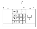
- FIG. 1 is a side view of the cargo storage device according to the embodiment.
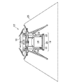
- FIG. 2 is a perspective view of an unmanned aerial vehicle carrying luggage.
- the luggage storage device 10 stores the luggage 14 transported by the unmanned aerial vehicle 12.
- the unmanned aerial vehicle 12 is an aircraft on which no person is boarded, and may be, for example, a battery-powered drone or an engine.
- the unmanned aerial vehicle 12 includes a motor and a battery for rotating the propeller 16, and includes a control unit, a storage unit, a communication unit, and a sensor unit (not shown).
- the unmanned aerial vehicle 12 includes a luggage storage unit 18.
- the luggage storage unit 18 includes a frame 20 having a space for storing the luggage 14.
- the frame 20 has a size such that the luggage 14 can be placed and fixed therein.
- the luggage storage unit 18 includes an arm 22 that supports the luggage 14 that is being delivered from falling and a stopper 24 that has a known locking mechanism.
- the luggage 14 is placed on the arm 22 and is fixed so as not to move in the horizontal direction by closing the stopper 24.
- the arm 22 can be opened and closed by the rotation of a motor (not shown). When the unmanned aerial vehicle 12 lands, the arm 22 opens downward, and the load 14 placed on the arm 22 falls by about several cm. It is like this.
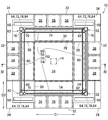
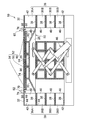
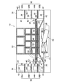
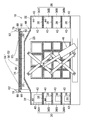
- FIG. 3 is a plan view of the cargo storage device 10 shown in FIG.
- FIG. 4 is a sectional view taken along line IV-IV of the load receiving and storing device 10 shown in FIG.
- the cargo storage device 10 has a stage 26 for unloading the luggage 14 from the unmanned aerial vehicle 12.
- the stage 26 has a transport surface 28 for unloading the luggage 14.
- the transport surface 28 is also for sliding movement of the luggage 14.
- the stage 26 has an inclined surface 30 that is outwardly lowered outside the transport surface 28.
- the unmanned aerial vehicle 12 is controlled to land on the stage 26 and take off after the unloading of the luggage 14 is completed.
- the stage 26 is large enough to allow the unmanned aerial vehicle 12 to take off and land.
- the cargo storage device 10 has a storage 32 for storing the luggage 14.
- the storage 32 is adjacent to the stage 26.
- the storage 32 is arranged around the stage 26.
- the storage 32 continuously surrounds the stage 26 to prevent intrusion of people.
- the storage 32 is provided with a wall 34 as needed.
- the storage 32 has a plurality of storage spaces 36.
- the plurality of storage spaces 36 are physically separated from each other.
- the plurality of storage spaces 36 include storage spaces 36A and 36B having different sizes.
- the plurality of storage spaces 36 are arranged in the vertical direction and further in the horizontal direction.
- Each of the plurality of storage spaces 36 has a storage surface 38 for storing the luggage 14.
- the storage surface 38 is adjacent to the inclined surface 30 of the stage 26. Between the transport surface 28 and the storage surface 38 is an inclined surface 30 that descends in the direction from the transport surface 28 to the storage surface 38.
- an inclined surface may be provided in the storage 32.
- Each storage space 36 has a carry-in port 40 that can be adjacent to the outer edge of the stage 26.
- Each storage space 36 has an outlet 42 on the opposite side of the carry-in port 40.
- the outlet 42 has a door 44 that can be opened and closed.
- the outlet 42 can be locked and unlocked.
- the take-out port 42 is locked when the luggage 14 is stored.
- the cargo storage device 10 has a lifter 46 for moving the stage 26 up and down.
- the lifter 46 is a known lifting device that uses hydraulic pressure.
- the lifter 46 is configured to lower the stage 26 from the unloading position 48 (see FIG. 9) of the luggage 14 to the storage position 50 (see FIG. 4) corresponding to the selected one of the plurality of storage spaces 36. ..
- the transfer surface 28 is higher than the storage surface 38 when the stage 26 is in the storage position 50, but the transfer surface 28 and the storage surface 38 are connected by the inclined surface 30. As a result, the luggage 14 can be slid from the transport surface 28 to the storage surface 38, and the luggage 14 can be stored in the storage space 36.
- the cargo storage device 10 has a pusher 52 (a jig for pushing) that is movable so as to push the load 14 on the stage 26.
- the pusher 52 includes a first bar 54 extending along the first direction D1 so that the load 14 hits the side surface.
- the pusher 52 includes a second bar 56 extending along a second direction D2 that intersects (for example, is orthogonal to) the first direction D1 so that the luggage 14 hits the side surface.
- the pusher 52 includes a third bar 58 extending along the first direction D1 so that the luggage 14 hits the side surface.
- the pusher 52 includes a fourth bar 60 extending along the second direction D2 so that the luggage 14 hits the side surface.
- the luggage 14 pushed by the pusher 52 slides in the two-dimensional direction (first direction D1 and second direction D2).
- One of the second bar 56 and the fourth bar 60 is used to push the load 14 in the first direction D1.
- One of the first bar 54 and the third bar 58 is used to push the load 14 in the second direction D2.
- At least one of the remaining bars not used to push the load 14 may be used as a guide for sliding movement of the load 14.
- the cargo storage device 10 has an actuator 62 for moving the pusher 52.
- the actuator 62 moves the pusher 52 horizontally. Thereby, the luggage 14 can be slid toward the selected one of the plurality of storage spaces 36.
- the actuator 62 has a mechanism that converts rotational movement into linear movement.
- the actuator 62 includes the first motor 64.
- a first screw shaft 66 is connected to the rotation shaft of the first motor 64.
- a first slider 68 having a screw hole is fitted in the first screw shaft 66.
- the first slider 68 can move in a direction intersecting the first direction D1 (for example, the second direction D2).
- the first slider 68 holds the first bar 54.
- the actuator 62 includes a second slider 70 that is movable in a direction intersecting the second direction D2 (for example, the first direction D1).
- the second slider 70 holds the second bar 56.
- the actuator 62 includes a second motor 72.
- a second screw shaft 74 is connected to the rotation shaft of the second motor 72, and a second slider 70 having a screw hole is fitted in the second screw shaft 74. As a result, the second motor 72 moves the second slider 70.
- the actuator 62 includes a third slider 76 that is movable in a direction intersecting the first direction D1 (for example, the second direction D2).
- the third slider 76 holds the third bar 58.
- the actuator 62 includes a third motor 78.
- a third screw shaft 80 is connected to the rotating shaft of the third motor 78, and a third slider 76 having a screw hole is fitted in the third screw shaft 80. As a result, the third motor 78 moves the third slider 76.
- the actuator 62 includes a fourth slider 82 that can move in a direction intersecting the second direction D2 (for example, the first direction D1).
- the fourth slider 82 holds the fourth bar 60.
- the actuator 62 includes a fourth motor 84.
- a fourth screw shaft 86 is connected to the rotation shaft of the fourth motor 84, and a fourth slider 82 having a screw hole is fitted in the fourth screw shaft 86. As a result, the fourth motor 84 moves the fourth slider 82.
- the luggage 14 can be stored in a selected one of the plurality of storage spaces 36. Can be stored.
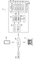
- FIG. 5 is a block diagram showing a delivery system including the goods storage device 10.
- the consignment storage device 10 has a memory 88.
- information regarding the unmanned aerial vehicle 12 [machine identification code (ID), delivery schedule, etc.] and information regarding the package 14 [package identification code (ID), size, password, etc.] Is memorized.
- the cargo storage device 10 has a processor 90.
- the processor 90 is arranged inside the wall 34, for example.
- the processor 90 includes a control unit 92 and a calculation unit 94.
- the processor 90 controls driving (ascending and descending) of the lifter 46.
- the processor 90 controls driving of the actuator 62 (first motor 64, second motor 72, third motor 78, and fourth motor 84).
- the processor 90 controls the security device 96.
- the security device 96 controls locking/unlocking of the take-out port 42 (door 44), and controls opening/closing of the carry-in port 40 as necessary.
- the password required to unlock the outlet 42 (door 44) is input on the control panel 98 (FIG. 1) attached to the wall 34.
- the cargo storage device 10 has a transceiver 100 for communication with the unmanned aerial vehicle 12.
- the storage device 10 has a wired interface 104 for communication with the management system 102.
- the communication is performed via the network 106.
- the unmanned aerial vehicle 12 and the storage device 10 are connected via a network 106 so that data can be transmitted and received.
- a management system 102 for remotely operating the unmanned aerial vehicle 12 is also connected to the network 106 so that data can be transmitted and received.
- the management system 102 is an air traffic control system (UTM: UAV Traffic Management) of the unmanned aerial vehicle 12 (UAV: Unmanned Aerial Vehicle) and manages flight routes and altitudes, data management/analysis, flight permission, real-time monitoring, It plays a role such as preventing entry into the no-fly area.
- UTM UAV Traffic Management
- UAV Unmanned Aerial Vehicle
- the terminal 108 is a portable terminal (including a tablet terminal or a smartphone) operated by a recipient, a personal computer, or the like.
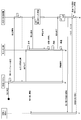
- FIG. 6 is a sequence diagram showing the processing of the delivery system including the goods storage device 10.
- the management system 102 receives a flight application and sets a flight schedule.
- the flight application is issued, for example, by the operator of the unmanned aerial vehicle 12 (the sender of the luggage 14).
- the delivery information is sent to the storage device 10.
- the delivery information includes information about the unmanned aerial vehicle 12 [machine identification code (ID), delivery schedule, etc.] and information about the package 14 [package identification code (ID), size].
- a consignment storage schedule is set.
- the processor 90 (calculation unit 94) selects one of the plurality of storage spaces 36 based on information on which of the plurality of storage spaces 36 is empty.
- the processor 90 (arithmetic unit 94) selects one of the plurality of storage spaces 36 based on the size information of the plurality of storage spaces 36.
- the consignment storage information is sent to the management system 102.
- the receipt storage information includes the landing acceptance date and time, the selected storage space number, and the password.
- the unmanned aerial vehicle 12 Upon receiving the flight permission from the management system 102, the unmanned aerial vehicle 12 departs for the cargo storage device 10.
- the cargo receiving and storing device 10 is notified of the approach of the unmanned aerial vehicle 12.
- the cargo storage device 10 may receive the position information of the unmanned aerial vehicle 12, and based on this, the processor 90 (calculation unit 94) may determine the approach of the unmanned aerial vehicle 12.
- the unmanned aerial vehicle 12 approaches the cargo storage device 10 prepares for landing acceptance.
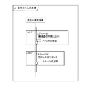
- FIG. 7 is a sequence diagram showing a landing acceptance preparation process.
- FIG. 8 is a figure which shows the storage of the luggage 14 conveyed previously.
- the pusher 52 is above the transport surface 28 at the time when the previously transported luggage 14 is stored in the storage space 36. Therefore, the actuator 62 is controlled to move the pusher 52 to the outside of the transport surface 28 before the start of the next unloading of the load 14. For example, the first bar 54 and the third bar 58 are moved to the outside of the transport surface 28, and the second bar 56 and the fourth bar 60 are moved to the outside of the transport surface 28. That is, when the pusher 52 is not outside the transport surface 28, the pusher 52 is moved because it interferes with the landing of the next unmanned aerial vehicle 12.
- the stage 26 is in the storage position 50 when the previously carried luggage 14 is stored in the storage space 36. Therefore, when the stage 26 is not at the unloading position 48 (FIG. 9), the stage 26 is raised. In this way, the lifter 46 is controlled so as to raise the stage 26 at the storage position 50 to the unloading position 48 before unloading the next load 14. This control may be performed at the latest before the start of unloading of the next luggage 14, and may be performed when the unmanned aerial vehicle 12 approaches (when the approach is detected).
- FIG. 9 is a diagram showing the cargo storage device 10 which is ready for landing acceptance.
- the landing permission is notified from the cargo storage device 10 to the unmanned aerial vehicle 12. This notification may be notified via the management system 102.
- the unmanned aerial vehicle 12 Upon receiving the landing clearance, the unmanned aerial vehicle 12 lands on the stage 26.
- the luggage 14 carried by the unmanned aerial vehicle 12 is unloaded on the stage 26.
- the unmanned aerial vehicle 12 lands on the stage 26 (transport surface 28), it is not necessary to ground the stage 26.
- the first bar 54 and the third bar 58 are located opposite each other outside the transport surface 28 and the second bar 56 and the fourth bar 60 are outside each other on the transport surface 28. Located on the other side.
- the unmanned aerial vehicle 12 is controlled to land on the stage 26 and take off after the unloading of the luggage 14 is completed.
- the unmanned aerial vehicle 12 takes off and moves to a safe position, the unmanned aerial vehicle 12 notifies the cargo storage device 10 that the takeoff is complete.
- FIG. 10 is a sequence diagram showing a process of storing the luggage 14.
- the storage space number for storing the luggage 14 is stored in the memory 88 (FIG. 5), and the stage 26 is lowered to the corresponding storage position 50.
- the stage 26 is lowered from the unloading position 48 of the luggage 14 to the storage position 50.
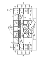
- FIG. 11 is a diagram showing the stage 26 lowered to the storage position 50. Then, the luggage 14 is slid. The slide movement is performed by controlling the actuator 62. The control method is determined by the storage space 36, and the information is stored in the memory 88 in advance.
- FIG. 12 is a diagram showing the first slide movement.
- the pusher 52 is moved horizontally and the load 14 is slid. Since this control is performed after the unloading of the luggage 14 is completed (after the unmanned aerial vehicle 12 has taken off), the pusher 52 does not contact the unmanned aerial vehicle 12.
- the luggage 14 slides into the selected storage space 36 by the two-dimensional movement on the transport surface 28.
- the unloaded luggage 14 is first slid to a position facing the carry-in port 40 of the selected storage space 36.
- the first bar 54 and the third bar move the luggage 14 along the second direction D2, and the first bar 54 located downstream of the luggage 14 in the movement direction is used.
- the third bar 58 is not used for sliding movement of the luggage 14, but is used as a guide for guiding the luggage 14 to the storage space 36. By the third bar 58, it is possible to regulate excessive slide movement and inclination of the luggage 14.
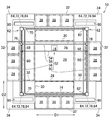
- FIG. 13 is a diagram showing the final slide movement.
- the luggage 14 is slid toward the carry-in port 40 of the selected storage space 36.
- the pusher 52 for example, the second bar 56
- the fourth bar 60 is not used, it is left on the outside of the transport surface 28.
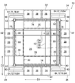
- FIG. 14 is a diagram showing the luggage 14 that enters the storage space 36.
- the luggage 14 that slides due to the horizontal movement of the pusher 52 enters a selected one of the plurality of storage spaces 36. Since the stage 26 has the inclined surface 30, the luggage 14 moves under the unused fourth bar 60. In this way, the luggage 14 is stored in the storage space 36.
- the take-out port 42 of the storage space 36 is controlled to be locked. For example, the door 44 is locked.
- a notification of receipt is sent to the recipient (terminal 108).
- the recipient unlocks the door 44 by electronic authentication such as input of a personal identification number. By doing so, security can be ensured.
- the recipient can unlock the take-out port 42 (door 44) by entering the password in the consignment storage device 10 (control panel 98). Then, the package 14 can be received.
- the take-out port 42 of the storage space 36 is unlocked, the corresponding carry-in port 40 may be closed. By doing so, it is possible to prevent a person from entering or contacting the stage 26 or the other storage spaces 36 through the storage space 36.
- the stage 26 is commonly used for unloading and sliding movement of the luggage 14, and by moving the pusher 52 horizontally, the luggage 14 can be stored in the selected one of the plurality of storage spaces 36. it can. Therefore, it is possible to receive and store the plurality of loads 14 with a simple mechanism.
- the present invention is not limited to the above-described embodiment, and various modifications can be made.
- the configuration described in the embodiments can be replaced with a configuration that is substantially the same, a configuration that achieves the same operational effect, or a configuration that can achieve the same object.
Landscapes
- Engineering & Computer Science (AREA)
- Mechanical Engineering (AREA)
- Food Science & Technology (AREA)
- Aviation & Aerospace Engineering (AREA)
- Warehouses Or Storage Devices (AREA)
- Supports Or Holders For Household Use (AREA)
Abstract
荷受け保管装置(10)は、無人航空機(12)で運搬された荷物(14)を荷卸しするためのステージ(26)と、荷物(14)を収納するために、ステージ(26)に隣接して、少なくとも鉛直方向に配列された複数の収納スペース(36)を有する収納庫(32)と、ステージ(26)を昇降させるためのリフタ(46)と、ステージ(26)の上で荷物(14)を押すように移動可能なプッシャ(52)と、プッシャ(52)を動かすためのアクチュエータ(62)と、を有する。リフタ(46)は、ステージ(26)を、荷物(14)の荷卸位置(48)から、複数の収納スペース(36)の選択された1つに対応する収納位置(50)に下げるように制御される。アクチュエータ(62)は、複数の収納スペース(36)の選択された1つに向けて荷物(14)をスライド移動させるために、プッシャ(52)を水平に動かすように制御される。
Description
本発明は、荷受け保管装置及び荷受け保管方法に関する。
近年、宅配ボックスあるいは宅配ロッカー等と呼ばれる、受取人が留守であっても荷物を受け取ることができる施設が普及しつつある。宅配ボックスは、集合住宅に設置される他、鉄道駅等の公共スペースに設置され、不特定多数のユーザにより利用されるものもある。最近ではドローン(無人航空機)を用いた無人配送が検討されている。
公知の技術では、複数のドローンによる複数荷物の荷受けや、複数の荷受人への複数荷物の保管を行うには、非効率的な場合があったり、複雑な機構が必要になったりしていた。
本発明は、複数荷物の荷受け及び保管を簡単な機構で可能にすることを目的とする。
(1)本発明に係る荷受け保管装置は、無人航空機で運搬された荷物を荷卸しするためのステージと、前記ステージに隣接して、少なくとも鉛直方向に配列された複数の収納スペースを有する収納庫と、前記ステージを昇降させるためのリフタと、前記ステージの上で前記荷物を押すように移動可能なプッシャと、前記プッシャを動かすためのアクチュエータと、を有し、前記リフタは、前記ステージを、前記荷物の荷卸位置から、前記複数の収納スペースの選択された1つに対応する収納位置に下げるように制御され、前記アクチュエータは、前記複数の収納スペースの前記選択された1つに向けて前記荷物をスライド移動させるために、前記プッシャを水平に動かすように制御されることを特徴とする。
本発明によれば、荷物の荷卸し及びスライド移動に共用されるステージと、水平に動かされるプッシャを含む簡単な構造で、複数の収納スペースの選択された1つに荷物を保管することができる。
(2)(1)に記載された荷受け保管装置において、前記ステージは、前記無人航空機の離着陸が可能な広さを有することを特徴としてもよい。
(3)(1)又は(2)に記載された荷受け保管装置において、前記収納庫は、前記ステージの周囲に配置されていることを特徴としてもよい。
(4)(3)に記載された荷受け保管装置において、前記収納庫は、前記ステージを途切れなく囲むことを特徴としてもよい。
(5)(3)又は(4)に記載された荷受け保管装置において、前記複数の収納スペースのそれぞれは、前記ステージの外縁に隣接可能な搬入口と、前記搬入口とは反対側の取出口と、を有することを特徴としてもよい。
(6)(5)に記載された荷受け保管装置において、前記複数の収納スペースは、隣同士が物理的に隔離されており、前記取出口は、施錠解錠できるようになっていることを特徴としてもよい。
(7)(6)に記載された荷受け保管装置において、前記取出口は、前記荷物が収納されているときには施錠されるように制御されることを特徴としてもよい。
(8)(6)又は(7)に記載された荷受け保管装置において、前記取出口は、開閉操作できる扉を有することを特徴としてもよい。
(9)(1)から(8)のいずれか1項に記載された荷受け保管装置において、前記ステージは、前記荷物の荷卸し及びスライド移動のための搬送面を有し、前記複数の収納スペースのそれぞれは、前記荷物を保管するための保管面を有し、前記荷物をスライド移動させるときに、前記搬送面が前記保管面よりも高い位置にいるように、前記リフタは制御され、前記収納庫及び前記ステージの少なくとも一方は、前記搬送面と前記保管面の間に、前記搬送面から前記保管面への方向に下がる傾斜面を有することを特徴としてもよい。
(10)(1)から(9)のいずれか1項に記載された荷受け保管装置において、前記プッシャは、前記荷物が側面に当たるように第1方向に沿って延びる第1バーと、前記荷物が側面に当たるように前記第1方向に交差する第2方向に沿って延びる第2バーと、を含み、前記アクチュエータは、前記第1バーを保持して前記第1方向に交差する方向に移動可能な第1スライダと、前記第2バーを保持して前記第2方向に交差する方向に移動可能な第2スライダと、を含むことを特徴としてもよい。
(11)(10)に記載された荷受け保管装置において、前記第1スライダは、前記第2方向に沿って移動可能であり、前記第2スライダは、前記第1方向に沿って移動可能であることを特徴としてもよい。
(12)(10)又は(11)に記載された荷受け保管装置において、前記アクチュエータは、前記第1スライダを移動させるための第1モータと、前記第2スライダを移動させるための第2モータと、を含むことを特徴としてもよい。
(13)(10)から(12)のいずれか1項に記載された荷受け保管装置において、前記プッシャは、前記荷物が側面に当たるように前記第1方向に沿って延びる第3バーと、前記荷物が側面に当たるように前記第2方向に沿って延びる第4バーと、を含み、前記アクチュエータは、前記第3バーを保持して前記第1方向に交差する方向に移動可能な第3スライダと、前記第4バーを保持して前記第2方向に交差する方向に移動可能な第4スライダと、を含むことを特徴としてもよい。
(14)(13)に記載された荷受け保管装置において、前記第3スライダは、前記第2方向に沿って移動可能であり、前記第4スライダは、前記第1方向に沿って移動可能であることを特徴としてもよい。
(15)(13)又は(14)に記載された荷受け保管装置において、前記アクチュエータは、前記第3スライダを移動させるための第3モータと、前記第4スライダを移動させるための第4モータと、を含むことを特徴としてもよい。
(16)(13)から(15)のいずれか1項に記載された荷受け保管装置において、前記アクチュエータは、前記荷物の荷卸しの間に、前記第1バー及び前記第3バーが前記搬送面の外側で相互に反対側に位置し、前記第2バー及び前記第4バーが前記搬送面の外側で相互に反対側に位置するように、制御されることを特徴としてもよい。
(17)(16)に記載された荷受け保管装置において、前記アクチュエータは、前記荷物の荷卸し前に、前記第1バー及び前記第3バーを前記搬送面の外側に移動させ、前記第2バー及び前記第4バーを前記搬送面の外側に移動させるように、制御されることを特徴としてもよい。
(18)(17)に記載された荷受け保管装置において、前記荷物を押すために、前記第1バー及び前記第3バーの一方及び前記第2バー及び前記第4バーの一方が使用され、前記荷物を押すために使用されない残りのバーの少なくとも1つは、前記荷物のスライド移動のためのガイドとして使用されることを特徴としてもよい。
(19)(1)から(18)のいずれか1項に記載された荷受け保管装置において、前記リフタは、前記荷物の荷卸しの間に前記ステージが前記荷卸位置にいるように、制御されることを特徴としてもよい。
(20)(19)に記載された荷受け保管装置において、前記リフタは、前記荷物の荷卸し前に前記収納位置にある前記ステージを前記荷卸位置に上昇させるように、制御されることを特徴としてもよい。
(21)(20)に記載された荷受け保管装置において、前記リフタは、前記無人航空機が接近したときに前記ステージを前記荷卸位置に上昇させるように、制御されることを特徴としてもよい。
(22)(1)から(21)のいずれか1項に記載された荷受け保管装置において、前記アクチュエータは、前記荷物の荷卸し完了後に前記荷物のスライド移動を開始するように、制御されることを特徴としてもよい。
(23)(22)に記載された荷受け保管装置において、前記無人航空機は、前記ステージに着陸して前記荷物の荷卸し完了後に離陸するように制御され、前記アクチュエータは、前記無人航空機の離陸後に前記荷物のスライド移動を開始するように、制御されることを特徴としてもよい。
(24)(1)から(23)のいずれか1項に記載された荷受け保管装置において、前記リフタ及び前記アクチュエータの駆動を制御するプロセッサをさらに有することを特徴としてもよい。
(25)(24)に記載された荷受け保管装置において、前記プロセッサは、前記複数の収納スペースのどれが空きであるかの情報に基づいて、前記複数の収納スペースの1つを選択することを特徴としてもよい。
(26)(24)又は(25)に記載された荷受け保管装置において、前記複数の収納スペースは、異なる大きさの収納スペースを含み、前記プロセッサは、前記複数の収納スペースの大きさの情報に基づいて、前記複数の収納スペースの1つを選択することを特徴としてもよい。
(27)本発明に係る荷受け保管方法は、無人航空機で運搬された荷物をステージに荷卸しするステップと、前記ステージを、前記荷物の荷卸位置から、前記ステージに隣接して少なくとも鉛直方向に配列された複数の収納スペースの選択された1つに対応する収納位置に下げるように、前記ステージの昇降が可能なリフタを制御するステップと、プッシャの水平な動きによって、前記荷物を、前記複数の収納スペースの前記選択された1つに向けて、前記ステージの上で押してスライド移動させるように、前記プッシャの移動が可能なアクチュエータを制御するステップと、を含むことを特徴とする。
本発明によれば、ステージは荷物の荷卸し及びスライド移動に共用され、プッシャを水平に動かすことで、複数の収納スペースの選択された1つに荷物を保管することができる。したがって、複数荷物の荷受け及び保管を簡単な機構で可能にすることができる。
(28)(27)に記載された荷受け保管方法において、前記複数の収納スペースのそれぞれは、前記ステージの外縁に隣接する搬入口と、前記搬入口とは反対側の取出口と、を有し、前記荷物が収納されているときには前記取出口を施錠するように制御することを特徴としてもよい。
(29)(27)又は(28)に記載された荷受け保管方法において、前記荷物を荷卸しする前に前記収納位置にある前記ステージを前記荷卸位置に上昇させるように、前記リフタを制御することを特徴としてもよい。
(30)(29)に記載された荷受け保管方法において、前記無人航空機が接近したときに前記ステージを前記荷卸位置に上昇させるように、前記リフタを制御することを特徴としてもよい。
(31)(27)から(30)のいずれか1項に記載された荷受け保管方法において、前記荷物の荷卸し完了後に前記荷物のスライド移動を開始するように、前記アクチュエータを制御することを特徴としてもよい。
(32)(27)から(31)のいずれか1項に記載された荷受け保管方法において、前記無人航空機は、前記ステージに着陸して前記荷物の荷卸し完了後に離陸するように制御され、前記無人航空機の離陸後に前記荷物のスライド移動を開始するように、前記アクチュエータを制御することを特徴としてもよい。
以下、本発明の実施形態について図面を参照して説明する。但し、本発明は、その要旨を逸脱しない範囲において様々な態様で実施することができ、以下に例示する実施形態の記載内容に限定して解釈されるものではない。
図1は、実施形態に係る荷受け保管装置の側面図である。図2は、荷物を運搬する無人航空機の斜視図である。荷受け保管装置10には、無人航空機12で運搬された荷物14が保管される。
[無人航空機12]
無人航空機12は、人が搭乗しない航空機であり、例えば、バッテリーで駆動されるドローンであってもよく、エンジンで駆動されてもよい。無人航空機12は、プロペラ16を回転させるためのモータやバッテリーを含み、制御部、記憶部、通信部及びセンサ部を含む(図示せず)。
無人航空機12は、人が搭乗しない航空機であり、例えば、バッテリーで駆動されるドローンであってもよく、エンジンで駆動されてもよい。無人航空機12は、プロペラ16を回転させるためのモータやバッテリーを含み、制御部、記憶部、通信部及びセンサ部を含む(図示せず)。
無人航空機12は、荷物格納部18を含む。荷物格納部18は、荷物14を格納するスペースを有するフレーム20を含む。フレーム20は、その内部に荷物14を載置して固定できる程度の大きさとなっている。荷物格納部18は、配送中の荷物14が下に落ちないように支えるアーム22と、公知のロック機構を有するストッパ24と、を含む。荷物14は、アーム22の上に載置され、ストッパ24を閉じることで水平方向に動かないように固定される。アーム22は、図示しないモータの回転により開閉可能になっており、無人航空機12が着陸するとアーム22が下側に向けて開き、アーム22の上に載置された荷物14が数cm程度落下するようになっている。
図3は、図1に示す荷受け保管装置10の平面図である。図4は、図1に示す荷受け保管装置10のIV-IV線断面図である。
[ステージ]
荷受け保管装置10は、無人航空機12から荷物14を荷卸しするためのステージ26を有する。ステージ26は、荷物14の荷卸しのための搬送面28を有する。搬送面28は、荷物14のスライド移動のためのものでもある。ステージ26は、搬送面28の外側に外方向に下がる傾斜面30を有する。無人航空機12は、ステージ26に着陸して荷物14の荷卸し完了後に離陸するように制御される。ステージ26は、無人航空機12の離着陸が可能な広さを有する。
荷受け保管装置10は、無人航空機12から荷物14を荷卸しするためのステージ26を有する。ステージ26は、荷物14の荷卸しのための搬送面28を有する。搬送面28は、荷物14のスライド移動のためのものでもある。ステージ26は、搬送面28の外側に外方向に下がる傾斜面30を有する。無人航空機12は、ステージ26に着陸して荷物14の荷卸し完了後に離陸するように制御される。ステージ26は、無人航空機12の離着陸が可能な広さを有する。
[収納庫]
荷受け保管装置10は、荷物14を収納するための収納庫32を有する。収納庫32は、ステージ26に隣接している。収納庫32は、ステージ26の周囲に配置されている。収納庫32は、人の侵入を防止するためにステージ26を途切れなく囲む。収納庫32には、必要に応じて壁34が設けられる。
荷受け保管装置10は、荷物14を収納するための収納庫32を有する。収納庫32は、ステージ26に隣接している。収納庫32は、ステージ26の周囲に配置されている。収納庫32は、人の侵入を防止するためにステージ26を途切れなく囲む。収納庫32には、必要に応じて壁34が設けられる。
収納庫32は、複数の収納スペース36を有する。複数の収納スペース36は、隣同士が物理的に隔離されている。複数の収納スペース36は、異なる大きさの収納スペース36A,36Bを含む。複数の収納スペース36は、鉛直方向に配列されており、さらに水平方向にも配列されている。
複数の収納スペース36のそれぞれは、荷物14を保管するための保管面38を有する。保管面38は、ステージ26が有する傾斜面30に隣接する。搬送面28と保管面38の間に、搬送面28から保管面38への方向に下がる傾斜面30がある。変形例として、傾斜面を収納庫32に設けてもよい。
それぞれの収納スペース36は、ステージ26の外縁に隣接可能な搬入口40を有する。それぞれの収納スペース36は、搬入口40とは反対側の取出口42を有する。取出口42は、開閉操作できる扉44を有する。取出口42は、施錠解錠できるようになっている。取出口42は、荷物14が収納されているときには施錠されるようになっている。
[リフタ]
荷受け保管装置10は、ステージ26を昇降させるためのリフタ46を有する。リフタ46は、油圧を使用した公知の昇降装置である。リフタ46は、ステージ26を、荷物14の荷卸位置48(図9参照)から、複数の収納スペース36の選択された1つに対応する収納位置50(図4参照)に下げるようになっている。
荷受け保管装置10は、ステージ26を昇降させるためのリフタ46を有する。リフタ46は、油圧を使用した公知の昇降装置である。リフタ46は、ステージ26を、荷物14の荷卸位置48(図9参照)から、複数の収納スペース36の選択された1つに対応する収納位置50(図4参照)に下げるようになっている。
ステージ26が収納位置50にあるとき、搬送面28は保管面38よりも高い位置にあるが、傾斜面30によって、搬送面28及び保管面38が接続される。これにより、搬送面28から保管面38への荷物14のスライド移動が可能になり、荷物14を収納スペース36に収納することができる。
[プッシャ]
荷受け保管装置10は、ステージ26の上で荷物14を押すように移動可能なプッシャ52(押すための治具)を有する。プッシャ52は、荷物14が側面に当たるように第1方向D1に沿って延びる第1バー54を含む。プッシャ52は、荷物14が側面に当たるように第1方向D1に交差(例えば直交)する第2方向D2に沿って延びる第2バー56を含む。プッシャ52は、荷物14が側面に当たるように第1方向D1に沿って延びる第3バー58を含む。プッシャ52は、荷物14が側面に当たるように第2方向D2に沿って延びる第4バー60を含む。
荷受け保管装置10は、ステージ26の上で荷物14を押すように移動可能なプッシャ52(押すための治具)を有する。プッシャ52は、荷物14が側面に当たるように第1方向D1に沿って延びる第1バー54を含む。プッシャ52は、荷物14が側面に当たるように第1方向D1に交差(例えば直交)する第2方向D2に沿って延びる第2バー56を含む。プッシャ52は、荷物14が側面に当たるように第1方向D1に沿って延びる第3バー58を含む。プッシャ52は、荷物14が側面に当たるように第2方向D2に沿って延びる第4バー60を含む。
プッシャ52で押された荷物14は、二次元方向(第1方向D1及び第2方向D2)にスライド移動する。第1方向D1に荷物14を押すために、第2バー56及び第4バー60の一方が使用される。第2方向D2に荷物14を押すために、第1バー54及び第3バー58の一方が使用される。荷物14を押すために使用されない残りのバーの少なくとも1つは、荷物14のスライド移動のためのガイドとして使用されてもよい。
[アクチュエータ]
荷受け保管装置10は、プッシャ52を動かすためのアクチュエータ62を有する。アクチュエータ62は、プッシャ52を水平に動かすようになっている。これにより、複数の収納スペース36の選択された1つに向けて荷物14をスライド移動させることができる。
荷受け保管装置10は、プッシャ52を動かすためのアクチュエータ62を有する。アクチュエータ62は、プッシャ52を水平に動かすようになっている。これにより、複数の収納スペース36の選択された1つに向けて荷物14をスライド移動させることができる。
アクチュエータ62は、回転運動を直線運動に変換する機構を有する。例えば、アクチュエータ62は、第1モータ64を含む。第1モータ64の回転軸には、第1ネジ軸66が連結されている。第1ネジ軸66には、ネジ穴を有する第1スライダ68がはまっている。これにより、第1モータ64の回転運動は、直線運動に変換されて、第1スライダ68を移動させることができる。第1スライダ68は、第1方向D1に交差する方向(例えば第2方向D2)に移動できるようになっている。第1スライダ68は第1バー54を保持する。
アクチュエータ62は、第2方向D2に交差する方向(例えば第1方向D1)に移動可能な第2スライダ70を含む。第2スライダ70は第2バー56を保持する。アクチュエータ62は、第2モータ72を含む。第2モータ72の回転軸には、第2ネジ軸74が連結されており、第2ネジ軸74には、ネジ穴を有する第2スライダ70がはまっている。これにより、第2モータ72は第2スライダ70を移動させるようになっている。
アクチュエータ62は、第1方向D1に交差する方向(例えば第2方向D2)に移動可能な第3スライダ76を含む。第3スライダ76は第3バー58を保持する。アクチュエータ62は、第3モータ78を含む。第3モータ78の回転軸には、第3ネジ軸80が連結されており、第3ネジ軸80には、ネジ穴を有する第3スライダ76がはまっている。これにより、第3モータ78は第3スライダ76を移動させるようになっている。
アクチュエータ62は、第2方向D2に交差する方向(例えば第1方向D1)に移動可能な第4スライダ82を含む。第4スライダ82は第4バー60を保持する。アクチュエータ62は、第4モータ84を含む。第4モータ84の回転軸には、第4ネジ軸86が連結されており、第4ネジ軸86には、ネジ穴を有する第4スライダ82がはまっている。これにより、第4モータ84は第4スライダ82を移動させるようになっている。
本実施形態によれば、荷物14の荷卸し及びスライド移動に共用されるステージ26と、水平に動かされるプッシャ52を含む簡単な構造で、複数の収納スペース36の選択された1つに荷物14を保管することができる。
[配送システム]
図5は、荷受け保管装置10を含む配送システムを示すブロック図である。荷受け保管装置10は、メモリ88を有する。メモリ88には、収納スペース36の使用状況の他に、無人航空機12に関する情報[機体識別符号(ID)、配送予定など]及び荷物14に関する情報[荷物識別符号(ID)、サイズ、パスワードなど]が記憶される。
図5は、荷受け保管装置10を含む配送システムを示すブロック図である。荷受け保管装置10は、メモリ88を有する。メモリ88には、収納スペース36の使用状況の他に、無人航空機12に関する情報[機体識別符号(ID)、配送予定など]及び荷物14に関する情報[荷物識別符号(ID)、サイズ、パスワードなど]が記憶される。
荷受け保管装置10は、プロセッサ90を有する。プロセッサ90は、例えば、壁34の内側に配置されている。プロセッサ90は、制御部92及び演算部94を含む。プロセッサ90(制御部92)は、リフタ46の駆動(上昇及び下降)を制御する。プロセッサ90(制御部92)は、アクチュエータ62(第1モータ64、第2モータ72、第3モータ78及び第4モータ84)の駆動を制御する。プロセッサ90(制御部92)は、セキュリティ装置96を制御する。セキュリティ装置96は、取出口42(扉44)の施錠解錠を制御し、必要に応じて、搬入口40の開閉を制御する。取出口42(扉44)の解錠に必要なパスワードは、壁34に取り付けられたコントロールパネル98(図1)で入力するようになっている。
荷受け保管装置10は、無人航空機12との通信のために、トランシーバ100を有する。荷受け保管装置10は、管理システム102との通信のために、有線インタフェース104を有する。通信はネットワーク106を介して行われる。無人航空機12と荷受け保管装置10は、ネットワーク106を介してデータ送受信可能に接続されている。ネットワーク106には、無人航空機12を遠隔操作するための管理システム102も、データ送受信可能に接続されている。
管理システム102は、無人航空機12(UAV: Unmanned Aerial Vehicle)の航空管制システム(UTM: UAV Traffic Management)であり、飛行ルートや高度の管理、データの管理・解析、飛行の許可、リアルタイムなモニタリング、飛行禁止エリアへの侵入を防ぐなどの役割を果たす。
荷物14の受取人の端末108には、ネットワーク106を介して、受け取りに必要な情報(受取場所、配送予定、収納スペース番号、パスワードなど)が通知される。端末108は、受取人が操作する携帯型端末(タブレット型端末やスマートフォンを含む)又はパーソナルコンピュータ等である。
図6は、荷受け保管装置10を含む配送システムの処理を示すシーケンス図である。管理システム102では、飛行申請を受けて飛行スケジュールが設定される。飛行申請は、例えば、無人航空機12の操縦者(荷物14の発送者)から出される。飛行スケジュールが決まると、配送情報が荷受け保管装置10に送られる。配送情報は、無人航空機12に関する情報[機体識別符号(ID)、配送予定など]及び荷物14に関する情報[荷物識別符号(ID)、サイズ]を含む。
[荷受け保管スケジュール設定]
荷受け保管装置10では、荷受け保管スケジュールが設定される。荷受け保管装置10では、プロセッサ90(演算部94)が、複数の収納スペース36のどれが空きであるかの情報に基づいて、複数の収納スペース36の1つを選択する。プロセッサ90(演算部94)は、複数の収納スペース36の大きさの情報に基づいて、複数の収納スペース36の1つを選択する。荷受け保管スケジュールが決まると、荷受け保管情報が管理システム102に送られる。荷受保管情報は、着陸受け入れ日時、選択された収納スペース番号、パスワードを含む。
荷受け保管装置10では、荷受け保管スケジュールが設定される。荷受け保管装置10では、プロセッサ90(演算部94)が、複数の収納スペース36のどれが空きであるかの情報に基づいて、複数の収納スペース36の1つを選択する。プロセッサ90(演算部94)は、複数の収納スペース36の大きさの情報に基づいて、複数の収納スペース36の1つを選択する。荷受け保管スケジュールが決まると、荷受け保管情報が管理システム102に送られる。荷受保管情報は、着陸受け入れ日時、選択された収納スペース番号、パスワードを含む。
管理システム102から飛行許可を受けると、無人航空機12は、荷受け保管装置10に向けて出発する。無人航空機12が順調に航行して、荷受け保管装置10に接近すると、荷受け保管装置10には、無人航空機12の接近が通知される。具体的には、無人航空機12の位置情報を荷受け保管装置10が受信し、これに基づいて、プロセッサ90(演算部94)で無人航空機12の接近を判断してもよい。無人航空機12が接近すると、荷受け保管装置10では着陸受け入れ準備を行う。
[着陸受け入れ準備]
図7は、着陸受け入れ準備の処理を示すシーケンス図である。図8は、先に運ばれた荷物14の収納を示す図である。
図7は、着陸受け入れ準備の処理を示すシーケンス図である。図8は、先に運ばれた荷物14の収納を示す図である。
先に運ばれた荷物14が収納スペース36に収納された時点で、プッシャ52は搬送面28の上方にある。そこで、アクチュエータ62は、次の荷物14の荷卸し開始前に、プッシャ52を搬送面28の外側に移動させるように制御される。例えば、第1バー54及び第3バー58を搬送面28の外側に移動させ、第2バー56及び第4バー60を搬送面28の外側に移動させる。つまり、プッシャ52が搬送面28の外側にない場合には、次の無人航空機12の着陸の妨げになるため、プッシャ52を移動させる。
先に運ばれた荷物14が収納スペース36に収納された時点で、ステージ26は収納位置50にある。そこで、ステージ26が荷卸し位置48(図9)にない場合、ステージ26を上昇させる。こうして、次の荷物14の荷卸し前に、収納位置50にあるステージ26を荷卸位置48に上昇させるように、リフタ46を制御する。この制御は、遅くとも次の荷物14の荷卸し開始前に行い、無人航空機12が接近したとき(接近を検出したとき)に行ってもよい。
図9は、着陸受け入れ準備が完了した荷受け保管装置10を示す図である。着陸受け入れ準備が完了すると、着陸許可が、荷受け保管装置10から無人航空機12に通知される。この通知は、管理システム102を介して通知されてもよい。
[着陸・荷卸し・離陸]
着陸許可を受けて、無人航空機12はステージ26に着陸する。無人航空機12で運搬された荷物14は、ステージ26に荷卸しされる。無人航空機12はステージ26(搬送面28)に着陸するが、ステージ26に接地することは必ずしも必要ではない。荷物14の荷卸しの間に、第1バー54及び第3バー58は搬送面28の外側で相互に反対側に位置し、第2バー56及び第4バー60は搬送面28の外側で相互に反対側に位置する。
着陸許可を受けて、無人航空機12はステージ26に着陸する。無人航空機12で運搬された荷物14は、ステージ26に荷卸しされる。無人航空機12はステージ26(搬送面28)に着陸するが、ステージ26に接地することは必ずしも必要ではない。荷物14の荷卸しの間に、第1バー54及び第3バー58は搬送面28の外側で相互に反対側に位置し、第2バー56及び第4バー60は搬送面28の外側で相互に反対側に位置する。
無人航空機12は、ステージ26に着陸して荷物14の荷卸し完了後に離陸するように制御される。無人航空機12は、離陸して安全な位置まで移動すると離陸が完了したことを、荷受け保管装置10に通知する。
[収納]
図10は、荷物14の収納の処理を示すシーケンス図である。上述したように、荷物14を収納する収納スペース番号がメモリ88(図5)に記憶されており、対応する収納位置50にステージ26を下げる。具体的には、リフタ46を制御することで、ステージ26を、荷物14の荷卸位置48から収納位置50に下降させる。
図10は、荷物14の収納の処理を示すシーケンス図である。上述したように、荷物14を収納する収納スペース番号がメモリ88(図5)に記憶されており、対応する収納位置50にステージ26を下げる。具体的には、リフタ46を制御することで、ステージ26を、荷物14の荷卸位置48から収納位置50に下降させる。
図11は、収納位置50に下げられたステージ26を示す図である。続いて、荷物14をスライド移動させる。スライド移動は、アクチュエータ62を制御することによって行う。制御方法は、収納スペース36によって決まっており、その情報が予めメモリ88に記憶されている。
図12は、最初のスライド移動を示す図である。アクチュエータ62を制御することで、プッシャ52を水平に動かして、荷物14をスライド移動させる。この制御は、荷物14の荷卸し完了後(無人航空機12の離陸後)に行うので、プッシャ52が無人航空機12に接触することはない。
荷物14は、搬送面28で二次元的な移動によって、選択された収納スペース36にスライド移動する。そのために、荷卸しされた荷物14を、まず、選択された収納スペース36の搬入口40に対向する位置にスライド移動させる。
図12に示す例では、第1バー54及び第3が、荷物14を第2方向D2に沿って移動させるようになっており、荷物14よりも移動方向の下流にある第1バー54を使用する。第3バー58は、荷物14のスライド移動には使用しないが、荷物14を収納スペース36へ導くためのガイドとして使用する。第3バー58によって、スライド移動のし過ぎや荷物14の傾きを規制することができる。
図13は、最後のスライド移動を示す図である。荷物14は、選択された収納スペース36の搬入口40に向かうようにスライド移動させられる。アクチュエータ62を制御することで、プッシャ52(例えば第2バー56)は水平に動く。なお、第4バー60は使用しないため、搬送面28に外側に配置したままにする。
図14は、収納スペース36に入る荷物14を示す図である。プッシャ52の水平な動きによってスライド移動する荷物14は、複数の収納スペース36の選択された1つに入る。ステージ26は、傾斜面30を有しているので、使用しない第4バー60の下を荷物14は移動する。こうして、荷物14は、収納スペース36に収納される。荷物14が収納されているときには、その収納スペース36の取出口42を施錠するように制御する。例えば、扉44を施錠する。
図6に示すように、収納が完了すると、受け取り可能の通知が受取人(端末108)に送られる。受取人は、暗証番号の入力などの電子認証によって扉44を解錠する。こうすることで、セキュリティを確保することができる。例えば、受取人は、荷受け保管装置10(コントロールパネル98)にパスワードを入力することで、取出口42(扉44)を解錠することができる。そして、荷物14の受け取りが可能になる。なお、収納スペース36の取出口42が解錠されているときには、対応する搬入口40を閉じるようにしてもよい。そうすることで、収納スペース36を通してステージ26や他の収納スペース36への人の侵入や接触を防止することができる。
本実施形態によれば、ステージ26は荷物14の荷卸し及びスライド移動に共用され、プッシャ52を水平に動かすことで、複数の収納スペース36の選択された1つに荷物14を保管することができる。したがって、複数荷物14の荷受け及び保管を簡単な機構で可能にすることができる。
本発明は、上述した実施形態に限定されるものではなく種々の変形が可能である。例えば、実施形態で説明した構成は、実質的に同一の構成、同一の作用効果を奏する構成又は同一の目的を達成することができる構成で置き換えることができる。
Claims (32)
- 無人航空機で運搬された荷物を荷卸しするためのステージと、
前記ステージに隣接して、少なくとも鉛直方向に配列された複数の収納スペースを有する収納庫と、
前記ステージを昇降させるためのリフタと、
前記ステージの上で前記荷物を押すように移動可能なプッシャと、
前記プッシャを動かすためのアクチュエータと、
を有し、
前記リフタは、前記ステージを、前記荷物の荷卸位置から、前記複数の収納スペースの選択された1つに対応する収納位置に下げるように制御され、
前記アクチュエータは、前記複数の収納スペースの前記選択された1つに向けて前記荷物をスライド移動させるために、前記プッシャを水平に動かすように制御されることを特徴とする荷受け保管装置。 - 請求項1に記載された荷受け保管装置において、
前記ステージは、前記無人航空機の離着陸が可能な広さを有することを特徴とする荷受け保管装置。 - 請求項1に記載された荷受け保管装置において、
前記収納庫は、前記ステージの周囲に配置されていることを特徴とする荷受け保管装置。 - 請求項3に記載された荷受け保管装置において、
前記収納庫は、前記ステージを途切れなく囲むことを特徴とする荷受け保管装置。 - 請求項3に記載された荷受け保管装置において、
前記複数の収納スペースのそれぞれは、前記ステージの外縁に隣接可能な搬入口と、前記搬入口とは反対側の取出口と、を有することを特徴とする荷受け保管装置。 - 請求項5に記載された荷受け保管装置において、
前記複数の収納スペースは、隣同士が物理的に隔離されており、
前記取出口は、施錠解錠できるようになっていることを特徴とする荷受け保管装置。 - 請求項6に記載された荷受け保管装置において、
前記取出口は、前記荷物が収納されているときには施錠されるように制御されることを特徴とする荷受け保管装置。 - 請求項6に記載された荷受け保管装置において、
前記取出口は、開閉操作できる扉を有することを特徴とする荷受け保管装置。 - 請求項1から8のいずれか1項に記載された荷受け保管装置において、
前記ステージは、前記荷物の荷卸し及びスライド移動のための搬送面を有し、
前記複数の収納スペースのそれぞれは、前記荷物を保管するための保管面を有し、
前記荷物をスライド移動させるときに、前記搬送面が前記保管面よりも高い位置にいるように、前記リフタは制御され、
前記収納庫及び前記ステージの少なくとも一方は、前記搬送面と前記保管面の間に、前記搬送面から前記保管面への方向に下がる傾斜面を有することを特徴とする荷受け保管装置。 - 請求項1から8のいずれか1項に記載された荷受け保管装置において、
前記プッシャは、前記荷物が側面に当たるように第1方向に沿って延びる第1バーと、前記荷物が側面に当たるように前記第1方向に交差する第2方向に沿って延びる第2バーと、を含み、
前記アクチュエータは、前記第1バーを保持して前記第1方向に交差する方向に移動可能な第1スライダと、前記第2バーを保持して前記第2方向に交差する方向に移動可能な第2スライダと、を含むことを特徴とする荷受け保管装置。 - 請求項10に記載された荷受け保管装置において、
前記第1スライダは、前記第2方向に沿って移動可能であり、
前記第2スライダは、前記第1方向に沿って移動可能であることを特徴とする荷受け保管装置。 - 請求項10に記載された荷受け保管装置において、
前記アクチュエータは、前記第1スライダを移動させるための第1モータと、前記第2スライダを移動させるための第2モータと、を含むことを特徴とする荷受け保管装置。 - 請求項10に記載された荷受け保管装置において、
前記プッシャは、前記荷物が側面に当たるように前記第1方向に沿って延びる第3バーと、前記荷物が側面に当たるように前記第2方向に沿って延びる第4バーと、を含み、
前記アクチュエータは、前記第3バーを保持して前記第1方向に交差する方向に移動可能な第3スライダと、前記第4バーを保持して前記第2方向に交差する方向に移動可能な第4スライダと、を含むことを特徴とする荷受け保管装置。 - 請求項13に記載された荷受け保管装置において、
前記第3スライダは、前記第2方向に沿って移動可能であり、
前記第4スライダは、前記第1方向に沿って移動可能であることを特徴とする荷受け保管装置。 - 請求項13に記載された荷受け保管装置において、
前記アクチュエータは、前記第3スライダを移動させるための第3モータと、前記第4スライダを移動させるための第4モータと、を含むことを特徴とする荷受け保管装置。 - 請求項13に記載された荷受け保管装置において、
前記アクチュエータは、前記荷物の荷卸しの間に、前記第1バー及び前記第3バーが前記搬送面の外側で相互に反対側に位置し、前記第2バー及び前記第4バーが前記搬送面の外側で相互に反対側に位置するように、制御されることを特徴とする荷受け保管装置。 - 請求項16に記載された荷受け保管装置において、
前記アクチュエータは、前記荷物の荷卸し前に、前記第1バー及び前記第3バーを前記搬送面の外側に移動させ、前記第2バー及び前記第4バーを前記搬送面の外側に移動させるように、制御されることを特徴とする荷受け保管装置。 - 請求項17に記載された荷受け保管装置において、
前記荷物を押すために、前記第1バー及び前記第3バーの一方及び前記第2バー及び前記第4バーの一方が使用され、
前記荷物を押すために使用されない残りのバーの少なくとも1つは、前記荷物のスライド移動のためのガイドとして使用されることを特徴とする荷受け保管装置。 - 請求項1に記載された荷受け保管装置において、
前記リフタは、前記荷物の荷卸しの間に前記ステージが前記荷卸位置にいるように、制御されることを特徴とする荷受け保管装置。 - 請求項19に記載された荷受け保管装置において、
前記リフタは、前記荷物の荷卸し前に前記収納位置にある前記ステージを前記荷卸位置に上昇させるように、制御されることを特徴とする荷受け保管装置。 - 請求項20に記載された荷受け保管装置において、
前記リフタは、前記無人航空機が接近したときに前記ステージを前記荷卸位置に上昇させるように、制御されることを特徴とする荷受け保管装置。 - 請求項1に記載された荷受け保管装置において、
前記アクチュエータは、前記荷物の荷卸し完了後に前記荷物のスライド移動を開始するように、制御されることを特徴とする荷受け保管装置。 - 請求項22に記載された荷受け保管装置において、
前記無人航空機は、前記ステージに着陸して前記荷物の荷卸し完了後に離陸するように制御され、
前記アクチュエータは、前記無人航空機の離陸後に前記荷物のスライド移動を開始するように、制御されることを特徴とする荷受け保管装置。 - 請求項1に記載された荷受け保管装置において、
前記リフタ及び前記アクチュエータの駆動を制御するプロセッサをさらに有することを特徴とする荷受け保管装置。 - 請求項24に記載された荷受け保管装置において、
前記プロセッサは、前記複数の収納スペースのどれが空きであるかの情報に基づいて、前記複数の収納スペースの1つを選択することを特徴とする荷受け保管装置。 - 請求項24に記載された荷受け保管装置において、
前記複数の収納スペースは、異なる大きさの収納スペースを含み、
前記プロセッサは、前記複数の収納スペースの大きさの情報に基づいて、前記複数の収納スペースの1つを選択することを特徴とする荷受け保管装置。 - 無人航空機で運搬された荷物をステージに荷卸しするステップと、
前記ステージを、前記荷物の荷卸位置から、前記ステージに隣接して少なくとも鉛直方向に配列された複数の収納スペースの選択された1つに対応する収納位置に下げるように、前記ステージの昇降が可能なリフタを制御するステップと、
プッシャの水平な動きによって、前記荷物を、前記複数の収納スペースの前記選択された1つに向けて、前記ステージの上で押してスライド移動させるように、前記プッシャの移動が可能なアクチュエータを制御するステップと、
を含むことを特徴とする荷受け保管方法。 - 請求項27に記載された荷受け保管方法において、
前記複数の収納スペースのそれぞれは、前記ステージの外縁に隣接する搬入口と、前記搬入口とは反対側の取出口と、を有し、
前記荷物が収納されているときには前記取出口を施錠するように制御することを特徴とする荷受け保管方法。 - 請求項27に記載された荷受け保管方法において、
前記荷物を荷卸しする前に前記収納位置にある前記ステージを前記荷卸位置に上昇させるように、前記リフタを制御することを特徴とする荷受け保管方法。 - 請求項29に記載された荷受け保管方法において、
前記無人航空機が接近したときに前記ステージを前記荷卸位置に上昇させるように、前記リフタを制御することを特徴とする荷受け保管方法。 - 請求項27から30のいずれか1項に記載された荷受け保管方法において、
前記荷物の荷卸し完了後に前記荷物のスライド移動を開始するように、前記アクチュエータを制御することを特徴とする荷受け保管方法。 - 請求項27から30のいずれか1項に記載された荷受け保管方法において、
前記無人航空機は、前記ステージに着陸して前記荷物の荷卸し完了後に離陸するように制御され、
前記無人航空機の離陸後に前記荷物のスライド移動を開始するように、前記アクチュエータを制御することを特徴とする荷受け保管方法。
Priority Applications (5)
| Application Number | Priority Date | Filing Date | Title |
|---|---|---|---|
| CN201880063274.1A CN111615350A (zh) | 2018-12-26 | 2018-12-26 | 货物接收保管装置及货物接收保管方法 |
| PCT/JP2018/047773 WO2020136742A1 (ja) | 2018-12-26 | 2018-12-26 | 荷受け保管装置及び荷受け保管方法 |
| US16/645,796 US11370608B2 (en) | 2018-12-26 | 2018-12-26 | Package receiving and holding apparatus and package receiving and holding method |
| EP18932971.7A EP3698680B1 (en) | 2018-12-26 | 2018-12-26 | Cargo receiving and storing device and cargo receiving and storing method |
| JP2019540135A JP6646797B1 (ja) | 2018-12-26 | 2018-12-26 | 荷受け保管装置及び荷受け保管方法 |
Applications Claiming Priority (1)
| Application Number | Priority Date | Filing Date | Title |
|---|---|---|---|
| PCT/JP2018/047773 WO2020136742A1 (ja) | 2018-12-26 | 2018-12-26 | 荷受け保管装置及び荷受け保管方法 |
Publications (1)
| Publication Number | Publication Date |
|---|---|
| WO2020136742A1 true WO2020136742A1 (ja) | 2020-07-02 |
Family
ID=69568056
Family Applications (1)
| Application Number | Title | Priority Date | Filing Date |
|---|---|---|---|
| PCT/JP2018/047773 WO2020136742A1 (ja) | 2018-12-26 | 2018-12-26 | 荷受け保管装置及び荷受け保管方法 |
Country Status (5)
| Country | Link |
|---|---|
| US (1) | US11370608B2 (ja) |
| EP (1) | EP3698680B1 (ja) |
| JP (1) | JP6646797B1 (ja) |
| CN (1) | CN111615350A (ja) |
| WO (1) | WO2020136742A1 (ja) |
Cited By (2)
| Publication number | Priority date | Publication date | Assignee | Title |
|---|---|---|---|---|
| JP2020138650A (ja) * | 2019-02-28 | 2020-09-03 | Ihi運搬機械株式会社 | 荷物受取り装置 |
| WO2023017609A1 (ja) * | 2021-08-12 | 2023-02-16 | Lomby株式会社 | 宅配ボックス及び荷物搬送システム |
Families Citing this family (6)
| Publication number | Priority date | Publication date | Assignee | Title |
|---|---|---|---|---|
| JP6971198B2 (ja) * | 2018-05-29 | 2021-11-24 | 京セラ株式会社 | 電子機器、電子機器の制御方法、及び電子機器の制御プログラム |
| CN110371562B (zh) * | 2018-09-29 | 2020-11-03 | 北京京东尚科信息技术有限公司 | 自提柜 |
| US20210371128A1 (en) * | 2020-05-27 | 2021-12-02 | Luis Rodriguez | Drone Landing Pad System for Receiving Parcels & Packages |
| CN111608095B (zh) * | 2020-06-08 | 2021-01-05 | 广东国安通航智能航空技术发展有限公司 | 一种无人机收纳悬停平台 |
| CN112241179A (zh) * | 2020-09-30 | 2021-01-19 | 北京二郎神科技有限公司 | 配送调度方法、控制器、装置和楼宇 |
| US20230044060A1 (en) * | 2021-07-09 | 2023-02-09 | Brian Carr | Delivery system and method |
Citations (5)
| Publication number | Priority date | Publication date | Assignee | Title |
|---|---|---|---|---|
| JPS5830608U (ja) * | 1981-08-21 | 1983-02-28 | 株式会社岡村製作所 | 昇降式荷出入装置 |
| JPS621092B2 (ja) | 1978-07-18 | 1987-01-12 | Bosch Gmbh Robert | |
| US5416329A (en) * | 1990-05-08 | 1995-05-16 | Wallac Oy | Apparatus for counting liquid scintillation samples |
| JP2017517466A (ja) | 2014-04-11 | 2017-06-29 | ドイチェ ポスト エージー | 無人運搬装置によって貨物を配達するための方法 |
| US20180105289A1 (en) * | 2014-01-02 | 2018-04-19 | Ryan Walsh | Receiving Appliance for Automated Deliveries |
Family Cites Families (18)
| Publication number | Priority date | Publication date | Assignee | Title |
|---|---|---|---|---|
| JP2007076919A (ja) | 2005-08-18 | 2007-03-29 | Murata Mach Ltd | 移載システムおよびそれを備える保管設備 |
| GB2552923A (en) * | 2016-04-13 | 2018-02-21 | Sydney Willcox Brian | Parcel depository |
| AU2017336221A1 (en) * | 2016-09-30 | 2019-04-18 | Inventio Ag | Assistance system for the delivery of mail consignments |
| EP4191547A1 (en) * | 2016-10-07 | 2023-06-07 | Quadient Technologies France | Secured electronic locker system |
| CN206491636U (zh) * | 2016-11-14 | 2017-09-15 | 深圳市智和创兴科技有限公司 | 便于无人机配送使用的快递柜 |
| CN106333595A (zh) * | 2016-11-14 | 2017-01-18 | 深圳市智和创兴科技有限公司 | 便于无人机配送使用的快递柜 |
| CN106552771B (zh) | 2016-12-05 | 2019-02-12 | 顺丰科技有限公司 | 无人机物流地面收纳平台系统及控制方法 |
| CN106938830B (zh) * | 2017-01-22 | 2023-06-06 | 广西大学 | 货物运载装置 |
| JP6201092B1 (ja) | 2017-03-10 | 2017-09-20 | 忍 有田 | 配達物無人自動受取装置 |
| CN207390180U (zh) * | 2017-09-30 | 2018-05-22 | 周鹏跃 | 存取货系统 |
| CN207390181U (zh) * | 2017-09-30 | 2018-05-22 | 周鹏跃 | 存取货系统 |
| CN207645127U (zh) * | 2017-10-26 | 2018-07-24 | 安吉智能物联技术有限公司 | 一种智能快递中转柜 |
| CN107720069A (zh) | 2017-10-26 | 2018-02-23 | 安吉智能物联技术有限公司 | 一种智能快递中转柜 |
| US11514596B2 (en) * | 2017-12-27 | 2022-11-29 | Panasonic Intellectual Property Management Co., Ltd. | Shape identification device and delivery box |
| US20190343317A1 (en) * | 2018-05-11 | 2019-11-14 | Walmart Apollo, Llc | Systems and methods for storing products dropped off by unmanned vehicles and for retrieving the products therefrom |
| US20200172337A1 (en) * | 2018-10-31 | 2020-06-04 | Walmart Apollo, Llc | Systems and Methods for Object Storage and Retrieval |
| US20200226539A1 (en) * | 2018-12-06 | 2020-07-16 | Walmart Apollo, Llc | Systems and Methods for Object Storage and Retrieval |
| EP3671667A1 (en) * | 2018-12-18 | 2020-06-24 | Neopost Technologies | Secured parcel locker system with token security |
-
2018
- 2018-12-26 US US16/645,796 patent/US11370608B2/en active Active
- 2018-12-26 WO PCT/JP2018/047773 patent/WO2020136742A1/ja unknown
- 2018-12-26 CN CN201880063274.1A patent/CN111615350A/zh active Pending
- 2018-12-26 JP JP2019540135A patent/JP6646797B1/ja active Active
- 2018-12-26 EP EP18932971.7A patent/EP3698680B1/en active Active
Patent Citations (5)
| Publication number | Priority date | Publication date | Assignee | Title |
|---|---|---|---|---|
| JPS621092B2 (ja) | 1978-07-18 | 1987-01-12 | Bosch Gmbh Robert | |
| JPS5830608U (ja) * | 1981-08-21 | 1983-02-28 | 株式会社岡村製作所 | 昇降式荷出入装置 |
| US5416329A (en) * | 1990-05-08 | 1995-05-16 | Wallac Oy | Apparatus for counting liquid scintillation samples |
| US20180105289A1 (en) * | 2014-01-02 | 2018-04-19 | Ryan Walsh | Receiving Appliance for Automated Deliveries |
| JP2017517466A (ja) | 2014-04-11 | 2017-06-29 | ドイチェ ポスト エージー | 無人運搬装置によって貨物を配達するための方法 |
Non-Patent Citations (1)
| Title |
|---|
| See also references of EP3698680A4 |
Cited By (3)
| Publication number | Priority date | Publication date | Assignee | Title |
|---|---|---|---|---|
| JP2020138650A (ja) * | 2019-02-28 | 2020-09-03 | Ihi運搬機械株式会社 | 荷物受取り装置 |
| JP7409776B2 (ja) | 2019-02-28 | 2024-01-09 | Ihi運搬機械株式会社 | 荷物受取り装置 |
| WO2023017609A1 (ja) * | 2021-08-12 | 2023-02-16 | Lomby株式会社 | 宅配ボックス及び荷物搬送システム |
Also Published As
| Publication number | Publication date |
|---|---|
| JPWO2020136742A1 (ja) | 2021-02-15 |
| CN111615350A (zh) | 2020-09-01 |
| JP6646797B1 (ja) | 2020-02-14 |
| US11370608B2 (en) | 2022-06-28 |
| EP3698680B1 (en) | 2023-01-18 |
| EP3698680A4 (en) | 2021-05-05 |
| EP3698680A1 (en) | 2020-08-26 |
| US20210214159A1 (en) | 2021-07-15 |
Similar Documents
| Publication | Publication Date | Title |
|---|---|---|
| WO2020136742A1 (ja) | 荷受け保管装置及び荷受け保管方法 | |
| US9260245B2 (en) | System and method for automatic storage and withdrawal of products with security restrictions | |
| CN109121387B (zh) | 使用无人飞行器的无人运输系统 | |
| JP6201092B1 (ja) | 配達物無人自動受取装置 | |
| WO2020057293A1 (zh) | 配送站点及配送方法 | |
| CN109205203B (zh) | 用于存放寄送物的接收容器和方法 | |
| US11526178B2 (en) | Location for unmanned aerial vehicle landing and taking off | |
| EP2630040B1 (en) | Automated self-serve baggage drop-off device | |
| WO2021191335A1 (en) | A dispatch system | |
| US20230044060A1 (en) | Delivery system and method | |
| EP4030977A1 (en) | Shipping system and control system for secure package delivery | |
| CN207658496U (zh) | 全自动保管箱输送与控制系统 | |
| US20220221875A1 (en) | Shipping system and control system for secure package delivery | |
| CN209506748U (zh) | 无人机投递终端站及无人机投递系统 | |
| CN111332675B (zh) | 货物自提设施、配送系统及配送方法 | |
| JP7001490B2 (ja) | ストッカおよびストッカシステム | |
| JP7409776B2 (ja) | 荷物受取り装置 | |
| US20230410025A1 (en) | Staging unmanned aerial vehicles at merchant facilities | |
| US20240117666A1 (en) | Autonomous vehicle and vending system | |
| AT510800A1 (de) | Übergabezone zum übergeben von warenpaletten | |
| WO2020194532A1 (ja) | 荷受け仕分け装置及び荷受け仕分け方法 | |
| CA3115276A1 (en) | Location for unmanned aerial vehicle landing and taking off |
Legal Events
| Date | Code | Title | Description |
|---|---|---|---|
| ENP | Entry into the national phase |
Ref document number: 2019540135 Country of ref document: JP Kind code of ref document: A |
|
| ENP | Entry into the national phase |
Ref document number: 2018932971 Country of ref document: EP Effective date: 20200318 |
|
| 121 | Ep: the epo has been informed by wipo that ep was designated in this application |
Ref document number: 18932971 Country of ref document: EP Kind code of ref document: A1 |
|
| NENP | Non-entry into the national phase |
Ref country code: DE |