WO2020129880A1 - 二次電池及びその製造方法 - Google Patents
二次電池及びその製造方法 Download PDFInfo
- Publication number
- WO2020129880A1 WO2020129880A1 PCT/JP2019/049116 JP2019049116W WO2020129880A1 WO 2020129880 A1 WO2020129880 A1 WO 2020129880A1 JP 2019049116 W JP2019049116 W JP 2019049116W WO 2020129880 A1 WO2020129880 A1 WO 2020129880A1
- Authority
- WO
- WIPO (PCT)
- Prior art keywords
- electrode
- positive electrode
- plate
- tab
- tabs
- Prior art date
Links
Images


Classifications
-
- H—ELECTRICITY
- H01—ELECTRIC ELEMENTS
- H01M—PROCESSES OR MEANS, e.g. BATTERIES, FOR THE DIRECT CONVERSION OF CHEMICAL ENERGY INTO ELECTRICAL ENERGY
- H01M10/00—Secondary cells; Manufacture thereof
- H01M10/05—Accumulators with non-aqueous electrolyte
- H01M10/058—Construction or manufacture
- H01M10/0587—Construction or manufacture of accumulators having only wound construction elements, i.e. wound positive electrodes, wound negative electrodes and wound separators
-
- H—ELECTRICITY
- H01—ELECTRIC ELEMENTS
- H01M—PROCESSES OR MEANS, e.g. BATTERIES, FOR THE DIRECT CONVERSION OF CHEMICAL ENERGY INTO ELECTRICAL ENERGY
- H01M50/00—Constructional details or processes of manufacture of the non-active parts of electrochemical cells other than fuel cells, e.g. hybrid cells
- H01M50/50—Current conducting connections for cells or batteries
- H01M50/531—Electrode connections inside a battery casing
- H01M50/538—Connection of several leads or tabs of wound or folded electrode stacks
-
- H—ELECTRICITY
- H01—ELECTRIC ELEMENTS
- H01M—PROCESSES OR MEANS, e.g. BATTERIES, FOR THE DIRECT CONVERSION OF CHEMICAL ENERGY INTO ELECTRICAL ENERGY
- H01M10/00—Secondary cells; Manufacture thereof
- H01M10/04—Construction or manufacture in general
- H01M10/0431—Cells with wound or folded electrodes
-
- H—ELECTRICITY
- H01—ELECTRIC ELEMENTS
- H01M—PROCESSES OR MEANS, e.g. BATTERIES, FOR THE DIRECT CONVERSION OF CHEMICAL ENERGY INTO ELECTRICAL ENERGY
- H01M50/00—Constructional details or processes of manufacture of the non-active parts of electrochemical cells other than fuel cells, e.g. hybrid cells
- H01M50/40—Separators; Membranes; Diaphragms; Spacing elements inside cells
- H01M50/463—Separators, membranes or diaphragms characterised by their shape
-
- H—ELECTRICITY
- H01—ELECTRIC ELEMENTS
- H01M—PROCESSES OR MEANS, e.g. BATTERIES, FOR THE DIRECT CONVERSION OF CHEMICAL ENERGY INTO ELECTRICAL ENERGY
- H01M50/00—Constructional details or processes of manufacture of the non-active parts of electrochemical cells other than fuel cells, e.g. hybrid cells
- H01M50/50—Current conducting connections for cells or batteries
- H01M50/531—Electrode connections inside a battery casing
- H01M50/533—Electrode connections inside a battery casing characterised by the shape of the leads or tabs
-
- H—ELECTRICITY
- H01—ELECTRIC ELEMENTS
- H01M—PROCESSES OR MEANS, e.g. BATTERIES, FOR THE DIRECT CONVERSION OF CHEMICAL ENERGY INTO ELECTRICAL ENERGY
- H01M50/00—Constructional details or processes of manufacture of the non-active parts of electrochemical cells other than fuel cells, e.g. hybrid cells
- H01M50/50—Current conducting connections for cells or batteries
- H01M50/531—Electrode connections inside a battery casing
- H01M50/536—Electrode connections inside a battery casing characterised by the method of fixing the leads to the electrodes, e.g. by welding
-
- H—ELECTRICITY
- H01—ELECTRIC ELEMENTS
- H01M—PROCESSES OR MEANS, e.g. BATTERIES, FOR THE DIRECT CONVERSION OF CHEMICAL ENERGY INTO ELECTRICAL ENERGY
- H01M10/00—Secondary cells; Manufacture thereof
- H01M10/05—Accumulators with non-aqueous electrolyte
- H01M10/052—Li-accumulators
-
- Y—GENERAL TAGGING OF NEW TECHNOLOGICAL DEVELOPMENTS; GENERAL TAGGING OF CROSS-SECTIONAL TECHNOLOGIES SPANNING OVER SEVERAL SECTIONS OF THE IPC; TECHNICAL SUBJECTS COVERED BY FORMER USPC CROSS-REFERENCE ART COLLECTIONS [XRACs] AND DIGESTS
- Y02—TECHNOLOGIES OR APPLICATIONS FOR MITIGATION OR ADAPTATION AGAINST CLIMATE CHANGE
- Y02E—REDUCTION OF GREENHOUSE GAS [GHG] EMISSIONS, RELATED TO ENERGY GENERATION, TRANSMISSION OR DISTRIBUTION
- Y02E60/00—Enabling technologies; Technologies with a potential or indirect contribution to GHG emissions mitigation
- Y02E60/10—Energy storage using batteries
-
- Y—GENERAL TAGGING OF NEW TECHNOLOGICAL DEVELOPMENTS; GENERAL TAGGING OF CROSS-SECTIONAL TECHNOLOGIES SPANNING OVER SEVERAL SECTIONS OF THE IPC; TECHNICAL SUBJECTS COVERED BY FORMER USPC CROSS-REFERENCE ART COLLECTIONS [XRACs] AND DIGESTS
- Y02—TECHNOLOGIES OR APPLICATIONS FOR MITIGATION OR ADAPTATION AGAINST CLIMATE CHANGE
- Y02P—CLIMATE CHANGE MITIGATION TECHNOLOGIES IN THE PRODUCTION OR PROCESSING OF GOODS
- Y02P70/00—Climate change mitigation technologies in the production process for final industrial or consumer products
- Y02P70/50—Manufacturing or production processes characterised by the final manufactured product
Definitions
- the present invention relates to a secondary battery and its manufacturing method.
- Secondary batteries such as alkaline rechargeable batteries and non-aqueous electrolyte rechargeable batteries are used as drive power sources for electric vehicles (EV) and hybrid electric vehicles (HEV, PHEV).
- EV electric vehicles
- HEV hybrid electric vehicles
- a battery case is composed of a bottomed cylindrical outer casing having an opening and a sealing plate for sealing the opening.
- An electrode body including a positive electrode plate, a negative electrode plate, and a separator is housed in the battery case together with an electrolyte.
- a positive electrode terminal and a negative electrode terminal are attached to the sealing plate.
- the positive electrode terminal is electrically connected to the positive electrode plate via the positive electrode current collector, and the negative electrode terminal is electrically connected to the negative electrode plate via the negative electrode current collector.
- a strip-shaped positive electrode plate having a plurality of positive electrode tabs and a strip-shaped negative electrode plate having a plurality of negative electrode tabs are wound by unwinding a strip-shaped separator to form a flat wound electrode body.
- Patent Document 1 proposes a secondary battery provided with (Patent Document 1 below).
- a secondary battery including a flat wound electrode body including an electrode plate having a plurality of tabs
- the plurality of tabs provided on the electrode plate are not uniformly spaced, and the tabs are provided at different intervals.
- the position of the part that becomes the winding start end of the electrode plate in the electrode body due to a problem that occurs during the cutting process of the electrode plate May not be known. In such a case, productivity may be reduced, and in some cases, a large loss of the electrode plate may occur.
- One object of the present invention is to provide a highly productive secondary battery.
- a secondary battery is A strip-shaped first electrode plate having a plurality of first electrode tabs; A strip-shaped second electrode plate having a plurality of second electrode tabs; A flat wound electrode body obtained by winding the first electrode plate and the second electrode plate with a strip-shaped separator interposed therebetween; A secondary battery comprising: a current collector connected in a state in which the plurality of first electrode tabs are stacked, An identification part is formed on a part of the first electrode tabs of the plurality of first electrode tabs.
- the tab is provided. It is possible to specify the winding start end portion of the first electrode plate in the spirally wound electrode body based on the identified portion. Therefore, the decrease in productivity can be effectively suppressed.
- the first electrode tab on which the identifying portion is formed is closer to the winding end end of the first electrode plate than the winding start end of the first electrode plate. It is preferably arranged.
- the identification part is a notch, an opening, or a mark formed in the first electrode tab.
- the identification part is a notch or an opening formed in the first electrode tab,
- the thickness of the first electrode tab at the edge of the opening or cutout is larger than the thickness of the first electrode tab at the center side of the first electrode tab than at the edge of the first electrode tab portion. Is preferred.
- the identification part is formed on the first electrode tab located on the outermost surface in the stacking direction of the first electrode tabs of the plurality of stacked first electrode tabs.
- the identification is made on the first electrode tabs which are the outermost surfaces of the stacked first electrode tabs and which are arranged on the outermost surface opposite to the current collector side. It is preferable that a part is formed.
- a method of manufacturing a secondary battery comprising: a current collector connected in a state in which the plurality of first electrode tabs are stacked, A step of producing a first electrode original plate having a plurality of first electrode tabs, and an original plate producing step of forming an identification portion on a part of the first electrode tabs of the plurality of first electrode tabs; An electrode plate producing step of producing the first electrode plate by cutting the first electrode original plate after the original plate producing step, And a connecting step of connecting the plurality of first electrode tabs to the current collector by laminating the plurality of first electrode tabs.
- the tab is provided. It is possible to specify the winding start end portion of the first electrode plate in the spirally wound electrode body based on the identified portion. Therefore, the decrease in productivity can be effectively suppressed.
- the identification part is an opening or a notch formed in the first electrode tab,
- the plurality of first electrode tabs and the current collector are joined by ultrasonic joining to form a joint, It is preferable that the identification portion is arranged closer to the tip end side of the first electrode tab than the joint portion.
- the connecting step it is preferable to sandwich the plurality of first electrode tabs and the current collector with an anvil and a horn, and vibrate the horn in the width direction of the first electrode tab to perform ultrasonic bonding.
- a highly productive secondary battery can be provided.
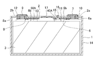
- FIG. 2 is a sectional view taken along line II-II in FIG. 1.
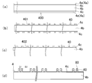
- A is a top view of a positive electrode original plate.
- B is a plan view of the positive electrode original plate after tab formation.
- C is a plan view of a final positive electrode original plate.
- D is a plan view of the positive electrode plate.
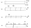
- A) is a top view of a negative electrode original plate.
- B) is a plan view of the negative electrode original plate after tab formation.
- C is a plan view of the final negative electrode original plate.
- D is a plan view of the negative electrode plate. It is a top view of the winding electrode body which concerns on embodiment.
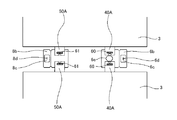
- FIG. 6 is a plan view of the vicinity of a joint between a positive electrode tab group and a second positive electrode current collector. It is sectional drawing of the VIII-VIII cross section of FIG. It is a figure which shows the surface by the side of an electrode body of the sealing plate after attaching a 1st positive electrode electrical power collector and a 1st negative electrode electrical power collector.
- the configuration of the prismatic secondary battery 20 as the secondary battery according to the embodiment will be described below.
- the present invention is not limited to the embodiments below.
- a prismatic secondary battery 20 includes a battery case 100 including a prismatic outer casing 1 having a bottomed rectangular tubular shape having an opening, and a sealing plate 2 for sealing the opening of the prismatic outer casing 1. ..
- the prismatic outer casing 1 and the sealing plate 2 are preferably made of metal.
- a wound electrode body 3 including a positive electrode plate and a negative electrode plate is accommodated in the prismatic outer casing 1 together with an electrolyte.
- a positive electrode tab group 40A including a plurality of positive electrode tabs 40 and a negative electrode tab group 50A including a plurality of negative electrode tabs 50 are provided at the end of the spirally wound electrode body 3 on the side of the sealing plate 2.
- the positive electrode tab group 40A is electrically connected to the positive electrode terminal 7 via the second positive electrode current collector 6b and the first positive electrode current collector 6a.
- the negative electrode tab group 50A is electrically connected to the negative electrode terminal 9 via the second negative electrode current collector 8b and the first negative electrode current collector 8a.
- the first positive electrode current collector 6a, the second positive electrode current collector 6b, and the positive electrode terminal 7 are preferably made of metal, and more preferably made of aluminum or aluminum alloy.
- An external insulating member 10 made of resin is disposed between the positive electrode terminal 7 and the sealing plate 2.
- An inner insulating member 11 made of resin is disposed between the first positive electrode current collector 6 a and the second positive electrode current collector 6 b and the sealing plate 2.
- the first negative electrode current collector 8a, the second negative electrode current collector 8b, and the negative electrode terminal 9 are preferably made of metal, and more preferably made of copper or a copper alloy. Further, the negative electrode terminal 9 preferably has a portion made of aluminum or an aluminum alloy and a portion made of copper or a copper alloy. In this case, it is preferable that the portion made of copper or a copper alloy is connected to the first negative electrode current collector 8a so that the portion made of aluminum or an aluminum alloy projects outward from the sealing plate 2.
- An outer insulating member 12 made of resin is arranged between the negative electrode terminal 9 and the sealing plate 2.
- An inner insulating member 13 made of resin is disposed between the first negative electrode current collector 8 a and the second negative electrode current collector 8 b and the sealing plate 2.
- an electrode body holder 14 made of a resin sheet made of resin is arranged between the spirally wound electrode body 3 and the prismatic outer casing 1.
- the electrode body holder 14 is preferably formed by bending an insulating sheet made of resin into a bag shape or a box shape.
- the sealing plate 2 is provided with an electrolytic solution injection hole 15, and the electrolytic solution injection hole 15 is sealed with a sealing member 16.
- the sealing plate 2 is provided with a gas discharge valve 17 that breaks when the pressure inside the battery case 100 exceeds a predetermined value and discharges the gas inside the battery case 100 to the outside of the battery case 100.
- Lithium nickel cobalt manganese composite oxide as a positive electrode active material, polyvinylidene fluoride (PVdF) as a binder, a carbon material as a conductive material, and N-methyl-2-pyrrolidone (NMP) as a dispersion medium are lithium nickel. Kneading is performed so that the mass ratio of cobalt-manganese composite oxide:PVdF:carbon material is 97.5:1:1.5 to prepare a positive electrode active material mixture layer slurry.
- Alumina powder, carbon material as a conductive material, polyvinylidene fluoride (PVdF) as a binder and N-methyl-2-pyrrolidone (NMP) as a dispersion medium were used, and the mass ratio of alumina powder:carbon material:PVdF was 83. Kneading is performed to obtain a protective layer slurry.
- the positive electrode active material mixture layer slurry and the positive electrode protective layer slurry produced by the above method are applied to both surfaces of a 15 ⁇ m-thick aluminum foil as a positive electrode core by a die coater. At this time, the positive electrode active material mixture layer slurry is applied to the center of the positive electrode core body in the width direction. Further, the positive electrode protective layer slurry is applied to both ends in the width direction of the region where the positive electrode active material mixture layer slurry is applied.
- the positive electrode core body coated with the positive electrode active material mixture layer slurry and the positive electrode protective layer slurry is dried to remove NMP contained in the positive electrode active material mixture layer slurry and the positive electrode protective layer slurry.
- the positive electrode active material mixture layer and the positive electrode protective layer are formed.
- the positive electrode active material mixture layer is compressed by passing between the pair of press rollers to obtain the positive electrode original plate 400.
- FIG. 3A is a plan view of the positive electrode original plate 400 manufactured by the above method.
- a positive electrode active material mixture layer 4b is formed on both surfaces of the strip-shaped positive electrode core body 4a along the longitudinal direction of the positive electrode core body 4a.
- the positive electrode protective layer 4c is formed in the vicinity of both ends in the width direction of the region where the positive electrode active material mixture layer 4b is formed.
- positive electrode core exposed portions 4e are formed at both ends in the width direction of the positive electrode original plate 400 along the longitudinal direction of the positive electrode original plate 400.
- the thickness of the positive electrode active material mixture layer 4b is preferably larger than the thickness of the positive electrode protective layer 4c.
- FIG. 3B is a plan view of the positive electrode original plate 401 after tab formation.
- the positive electrode original plate 401 after tab formation is produced.
- the cutting of the positive electrode original plate 400 can be performed by irradiation with an energy ray such as a laser, a mold, a cutter, or the like.
- an energy ray such as a laser, a mold, a cutter, or the like.
- a plurality of positive electrode tabs 40 are formed at both ends in the width direction of the positive electrode original plate 401 after tab formation.
- the positive electrode tab 40 includes the positive electrode core exposed portion 4e. As shown in FIG.
- the positive electrode is formed so that the positive electrode protective layer 4c remains at the root of the positive electrode tab 40 and the end of the positive electrode original plate 401 after the tab is formed between adjacent positive electrode tabs 40.
- the original plate 400 can be cut.
- the positive electrode protective layer 4c is not an essential component and can be omitted.
- the portion where the positive electrode active material mixture layer 4b is formed is cut so that the positive electrode protective layer 4c does not remain at the end portion of the positive electrode original plate 401 after the tab formation, which is formed between the adjacent positive electrode tabs 40. You may In addition, it is preferable that the positive electrode original plate 400 is cut by irradiation with energy rays to form the positive electrode tab 40.
- An identification unit 80 is formed on a part of the plurality of positive electrode tabs 40.
- the identification portion 80 is a cutout portion formed on the outer peripheral edge of the positive electrode tab 40.
- the identification portion 80 is preferably provided when the positive electrode tab 40 is formed. However, the identification portion 80 may be formed on the positive electrode tab 40 after forming the positive electrode tab 40.
- FIG. 3C is a plan view of the final positive electrode original plate 402.
- the positive electrode original plate 401 after tab formation is cut at the center in the width direction along the longitudinal direction of the positive electrode original plate 401 after tab formation.
- the final positive electrode original plate 402 whose size in the width direction is the size of the positive electrode plate 4 is obtained. That is, the final positive electrode original plate 402 is in a state before being cut to the length of the positive electrode plate 4 in the length direction.
- FIG. 3D is a plan view of the positive electrode plate 4.
- the final positive electrode original plate 402 is cut into a predetermined length to form the positive electrode plate 4. At this time, it is preferable to cut the final positive electrode original plate 402 at a position at a predetermined distance from the identifying portion 80, with the identifying portion 80 formed on a part of the positive electrode tab 40 as a base point.
- the final positive electrode original plate 402 in the manufacturing process of the wound electrode body described later. That is, it is preferable to cut a portion that is a winding end portion (a winding start end in the next positive electrode plate 4) while or after winding the wound electrode body.
- the identification part 80 provided on the positive electrode tab 40. By reading, it is possible to identify the portion that becomes the winding start end portion of the positive electrode plate 4, and it is possible to effectively suppress a decrease in productivity.
- the wound electrode body 3 be provided with the positive electrode tab 40 for each layer of the positive electrode plate 4. That is, it is preferable that the number of stacked positive electrode plates 4 and the number of stacked positive electrode tabs 40 are the same or substantially the same. Therefore, as shown in FIG. 3D, in the positive electrode plate 4, a portion where the positive electrode tabs 40 are arranged at a short distance (D1) and a portion where the positive electrode tabs 40 are arranged at a long distance (D2). There is an arranged part. Then, in the wound electrode body 3, the winding diameter of the positive electrode plate 4 increases from the winding center toward the outside.
- the distances D1 and D2 are gradually increased from the winding start end to the winding end end of the positive electrode plate 4 so that the positions of the positive electrode tabs 40 are aligned. It is preferable to set it to be large. The same applies to the negative electrode tab 50 described later.
- the distance from the position of the positive electrode tab 40 provided with the identification portion 80 to the winding end portion (cutting portion) of the positive electrode plate 4 is shorter.
- the distance from the reading of the identification portion 80 to the winding end end (cutting portion) of the positive electrode plate 4 is large, the winding end end (cutting portion) of the positive electrode plate 40 from the positive electrode tab 40 where the identification portion 80 is formed.
- the final positive electrode original plate 402 is cut by identifying the winding end part (cutting part) of the positive electrode plate 4 based on the number and distance of the positive electrode tabs 40 arranged up to (4), the accuracy of the length of the positive electrode plate 4 is ensured. Becomes difficult to do.
- the positive electrode tab 40 on which the identification portion 80 is formed is preferably arranged at a position closer to the winding end end of the positive electrode plate 4 than the winding start end of the positive electrode plate 4. .. Further, it is more preferable that the positive electrode tab 40 located closest to the winding end portion of the positive electrode plate 4 is provided with the identifying portion 80.
- the identification portion 80 is provided on at least one of the positive electrode tab 40 at the position closest to the winding end end of the positive electrode plate 4 and the positive electrode tab 40 at the position closest to the second winding end end of the positive electrode plate 4. More preferably, it is provided.
- the positive electrode tab 40 located closest to the winding end of the positive electrode plate 4 and the positive electrode tab located second closest to the winding end of the positive electrode plate 4 are provided with the identifying portions 80, respectively. Good. The same applies to the identification portion 81 provided on the negative electrode tab 50 described later.
- a single positive electrode plate 4 has a plurality of positive electrode tabs 40.
- the identification portion 80 is provided only on a part of the plurality of positive electrode tabs 40. That is, the identification portion 80 is not provided on all the positive electrode tabs 40.
- the negative electrode active material mixture layer slurry prepared by the above method is applied to both surfaces of a copper foil having a thickness of 8 ⁇ m as a negative electrode core by a die coater.
- the negative electrode core body to which the negative electrode active material mixture layer slurry is applied is dried to remove water in the negative electrode active material mixture layer slurry. As a result, the negative electrode active material mixture layer is formed. Then, the negative electrode active material mixture layer is compressed by passing between a pair of press rollers to obtain the negative electrode original plate 500.
- FIG. 4A is a plan view of the negative electrode original plate 500 manufactured by the above method.
- Negative electrode active material mixture layers 5b are formed on both surfaces of the strip-shaped negative electrode core 5a along the longitudinal direction of the negative electrode core 5a.
- negative electrode core exposed portions 5c are formed at both ends of the negative electrode original plate 500 in the width direction along the longitudinal direction of the negative electrode original plate 500.
- FIG. 4B is a plan view of the negative electrode original plate 501 after tab formation.
- the negative electrode original plate 501 after tab formation is produced.
- the cutting of the negative electrode original plate 500 can be performed by irradiation with energy rays such as a laser, a mold, or a cutter.
- a plurality of negative electrode tabs 50 are formed at both ends in the width direction of the negative electrode original plate 501 after tab formation.
- the negative electrode tab 50 includes the negative electrode core exposed portion 5c.
- it is preferable that the negative electrode original plate 500 is cut by irradiation with energy rays to form the negative electrode tab 50.
- An identification portion 81 is formed on a part of the plurality of negative electrode tabs 50.
- the identification portion 81 is a cutout portion formed on the outer peripheral edge of the negative electrode tab 50.
- the identification portion 81 is preferably provided when forming the negative electrode tab 50. However, the identification portion 81 may be formed on the negative electrode tab 50 after forming the negative electrode tab 50.
- FIG. 4C is a plan view of the final negative electrode original plate 502.
- the negative electrode original plate 501 after tab formation is cut at the central portion in the width direction along the longitudinal direction of the negative electrode original plate 501 after tab formation.
- the final negative electrode original plate 502 whose size in the width direction is the size of the negative electrode plate 5 is obtained. That is, the final negative electrode original plate 502 is in a state before being cut to the length of the negative electrode plate 5 in the length direction.
- FIG. 4D is a plan view of the negative electrode plate 5.
- the final negative electrode original plate 502 is cut into a predetermined length to obtain the negative electrode plate 5. At this time, it is preferable that the final negative electrode original plate 502 be cut at a position located at a predetermined distance from the identification portion 81, with the identification portion 81 formed on a part of the negative electrode tab 50 as a base point.
- the identification part 81 provided on the negative electrode tab 50. By reading, it is possible to identify the portion that becomes the winding start end portion of the negative electrode plate 5, and it is possible to effectively suppress a decrease in productivity.
- a single negative electrode plate 5 has a plurality of negative electrode tabs 50.
- the identification portion 81 is provided only on a part of the plurality of negative electrode tabs 50. That is, the identification portion 81 is not provided on all the negative electrode tabs 50.
- FIG. 5 is a plan view of the spirally wound electrode body 3.
- a positive electrode tab group 40A including a plurality of positive electrode tabs 40 and a negative electrode tab group 50A including a plurality of negative electrode tabs 50 are provided at one end in the direction in which the winding axis extends.
- the identification portion 80 is formed on the positive electrode tab 40 located on the outermost surface in the stacking direction of the positive electrode tabs 40. Therefore, in the positive electrode tab group 40A, it is possible to easily confirm in which part the identification portion 80 is located.
- the identification portion 81 is formed on the negative electrode tab 50 located on the outermost surface in the stacking direction of the negative electrode tabs 50. Therefore, in which portion of the negative electrode tab group 50A the identification portion 81 is located can be easily confirmed.
- the identification portion 80 is formed at a position closer to the winding end end than the winding start end in the wound electrode body 3 in the longitudinal direction of the positive electrode plate 4.
- the identification portion 81 be formed at a position closer to the winding end end than the winding start end in the wound electrode body 3 in the longitudinal direction of the negative electrode plate 5.
- the number of stacked positive electrode tabs 40 is preferably 0.8 ⁇ N1 or more, and 0.9 ⁇ N1 or more. More preferably.
- the number of stacked negative electrode tabs 50 is preferably 0.8 ⁇ N2 or more, and 0.9 ⁇ N2 or more. More preferably.
- the positive electrode tab group 40A of the two wound electrode bodies 3 is connected to the second positive electrode current collector 6b, and the negative electrode tab group 50A of the two wound electrode bodies 3 is connected to the second negative electrode current collector. Connect to body 8b.
- the positive electrode tab group 40A is bonded to the second positive electrode current collector 6b to form the bonding portion 60.
- the negative electrode tab group 50A is bonded to the second negative electrode current collector 8b to form a bonding portion 61.
- ultrasonic welding ultrasonic joining
- resistance welding resistance welding
- laser welding or the like can be used.
- a thin portion 6c is formed in the second positive electrode current collector 6b, and a current collector opening 6d is formed in the thin portion 6c.
- the second positive electrode current collector 6b is joined to the first positive electrode current collector 6a.
- a current collector through hole 6e is formed in the second positive electrode current collector 6b at a position facing the electrolyte solution injection hole 15 of the sealing plate 2.
- a thin portion 8c is formed on the second negative electrode current collector 8b, and a current collector opening 8d is formed in the thin portion 8c.
- the second negative electrode current collector 8b is joined to the first negative electrode current collector 8a.
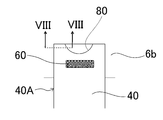
- FIG. 7 is a plan view of the vicinity of the joint between the positive electrode tab group 40A and the second positive electrode current collector 6b in FIG.
- the identification portion 80 is formed on the positive electrode tab 40 located on the outermost surface in the stacking direction. Therefore, it is possible to reliably prevent the identification portion 80 from being arranged at the position where the joint portion 60 is formed.
- the positive electrode tab 40 is located on the outermost surface in the stacking direction of the positive electrode tab 40 and on the outermost surface opposite to the second positive electrode current collector 6b side. It is possible to more reliably prevent the identification portion 80 from being arranged at the position where the portion 60 is formed. Therefore, it is possible to effectively prevent the strength of the joint portion 60 between the positive electrode tab group 40A and the second positive electrode current collector 6b from being varied, so that the secondary battery has higher reliability.
- the positive electrode tab group 40A is connected to the second positive electrode current collector 6b. The position of the identification unit 80 can be confirmed before placing it on top.
- the positive electrode tab group 40A it is difficult to stack a plurality of positive electrode tabs 40 without displacement. Therefore, when the identifying portion 80 is provided on the positive electrode tab 40 located at the center of the positive electrode tab 40 in the stacking direction, it is difficult to accurately grasp the position of the identifying portion 80. Therefore, in some cases, the joint portion 60 is formed in the portion where the identification portion 80 is formed, and the reliability of the connection portion between the positive electrode tab group 40A and the second positive electrode current collector 6b may be reduced.
- the positive electrode tab 40 located on the outermost surface in the stacking direction of the positive electrode tabs 40 is provided with the identifying portion 80. Further, in the positive electrode tab group 40A, it is preferable that the positive electrode tab 40 located on the outermost surface on the side opposite to the second positive electrode current collector 6b side is provided with the identifying portion 80.
- the position where the identification portion 80 is formed on the positive electrode tab 40 is more than the bonding portion 60 in the protruding direction from the main body portion of the positive electrode plate 4 of the positive electrode tab 40 (the region where the positive electrode active material mixture layer 4b is formed). It is preferably provided on the tip side of the positive electrode tab 40.
- the positive electrode tab group 40A and the second positive electrode current collector 6b When ultrasonic welding the positive electrode tab group 40A and the second positive electrode current collector 6b, ultrasonic welding is performed by sandwiching the positive electrode tab group 40A and the second positive electrode current collector 6b with an anvil and a horn and vibrating the horn. ..
- the horn is preferably vibrated in the width direction of the positive electrode tab 40 (left and right direction in FIG. 7).
- the identification portion 80 is formed closer to the tip end side (upper end side in FIG. 7) of the positive electrode tab 40 than the portion to be the bonding portion 60, so that the positive electrode tab 40 is effectively damaged or broken. Can be suppressed. That is, it is possible to effectively prevent the positive electrode tab 40 from being damaged or damaged by vibration during ultrasonic welding.
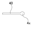
- FIG. 8 is a cross-sectional view of the positive electrode tab 40 taken along the line VIII-VIII in FIG. 7.
- a thick portion 4x which is thicker than the thickness of the central portion of the positive electrode tab 40, is formed at the edge portion of the cutout serving as the identification portion 80 provided in the positive electrode tab 40. Since the thick portion 4x is formed, it is possible to effectively prevent the positive electrode tab 40 from being damaged or damaged with the identification portion 80 as a base point.
- the thickness of the thick portion 4x is preferably 1.1 times or more, and more preferably 1.2 times or more the thickness of the central portion of the positive electrode tab 40.
- the configuration and the effect thereof described for the positive electrode tab group 40A are the same for the negative electrode tab group 50A.
- the identification portion is a notch has been described, the same applies when the identification portion is an opening. In consideration of productivity and reliability, the identification portion is preferably a cutout rather than an opening.
- FIG. 9 is a view showing a surface of the sealing plate 2 on which the respective components are attached, which is located on the inner side of the battery. Each component is attached to the sealing plate 2 as follows.
- the outer insulating member 10 is arranged on the outer surface of the battery around the positive electrode terminal insertion hole 2a of the sealing plate 2.
- the inner insulating member 11 and the first positive electrode current collector 6a are arranged on the inner surface of the battery around the positive electrode terminal insertion hole 2a of the sealing plate 2.
- the positive electrode terminal 7 is provided from the outside of the battery to the through hole of the outer insulating member 10, the positive electrode terminal insertion hole 2a of the sealing plate 2, the through hole of the inner insulating member 11 and the through hole of the first positive electrode current collector 6a.
- the tip of the positive electrode terminal 7 is crimped onto the first positive electrode current collector 6a.
- the positive electrode terminal 7 and the first positive electrode current collector 6a are fixed to the sealing plate 2. It is preferable to weld the crimped portion of the positive electrode terminal 7 and the first positive electrode current collector 6a.
- the outer insulating member 12 is arranged on the outer surface of the battery around the negative electrode terminal insertion hole 2b of the sealing plate 2.
- the inner insulating member 13 and the first negative electrode current collector 8a are arranged on the inner surface of the battery around the negative electrode terminal insertion hole 2b of the sealing plate 2.
- the negative electrode terminal 9 is provided from the outside of the battery to the through hole of the outer insulating member 12, the negative electrode terminal insertion hole 2b of the sealing plate 2, the through hole of the inner insulating member 13, and the through hole of the first negative electrode current collector 8a.
- the tip of the negative electrode terminal 9 is crimped onto the first negative electrode current collector 8a.
- the negative electrode terminal 9 and the first negative electrode current collector 8a are fixed to the sealing plate 2. It is preferable to weld the crimped portion of the negative electrode terminal 9 and the first negative electrode current collector 8a.
- a liquid injection opening 11 a is provided in a portion of the inner insulating member 11 that faces the electrolyte liquid injection hole 15 provided in the sealing plate 2.
- a cylindrical portion 11b is provided at the edge of the liquid injection opening 11a.
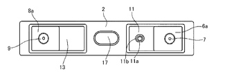
- FIG. 10 shows the inner side of the battery of the sealing plate 2 after the second positive electrode current collector 6b is attached to the first positive electrode current collector 6a and the second negative electrode current collector 8b is attached to the first negative electrode current collector 8a. It is a figure which shows a surface.
- the second positive electrode current collector 6b to which the positive electrode tab group 40A is connected is arranged on the inner insulating member 11 such that a part thereof overlaps the first positive electrode current collector 6a. Then, by irradiating the thin portion 6c with a laser, the second positive electrode current collector 6b and the first positive electrode current collector 6a are joined. As a result, the joint portion 62 is formed.
- the second negative electrode current collector 8b to which the negative electrode tab group 50A is connected is arranged on the inner insulating member 13 such that a part thereof overlaps the first negative electrode current collector 8a. Then, by irradiating the thin portion 8c with a laser, the second negative electrode current collector 8b and the first negative electrode current collector 8a are joined. As a result, the joint portion 63 is formed.
- the two positive electrode tab groups 40A and the two negative electrode tab groups 50A are curved so that the upper surface of the one spirally wound electrode body 3 and the upper surface of the other spirally wound electrode body 3 in FIG. 10 are in direct contact with each other or through other members. Let As a result, the two spirally wound electrode bodies 3 are combined into one. Then, the two spirally wound electrode bodies 3 are arranged in the electrode body holder 14 made of an insulating sheet formed in a box shape or a bag shape.
- the one positive electrode tab group 40A and the other positive electrode tab group 40A are curved in different directions.
- the one negative electrode tab group 50A and the other negative electrode tab group 50A are curved in different directions.
- the identifying portions are provided on both the positive electrode tab and the negative electrode tab is shown, but the identifying portions may be provided on only one side.
- the positive electrode current collector and the negative electrode current collector may each include one part.
- the positive electrode current collector and the negative electrode current collector are each one component, after connecting the positive electrode tab group and the negative electrode tab group to the positive electrode current collector and the negative electrode current collector, respectively, the positive electrode current collector and the negative electrode current collector Is preferably connected to each of the positive electrode terminal and the negative electrode terminal attached to the sealing plate.
- a current cutoff mechanism may be provided in the conductive path between the positive electrode plate and the positive electrode terminal.
- the identification portion may be an opening formed in the tab.
- a mark may be formed on the tab as the identification portion.
- printing, coating with a paint, a laser marker, or the like can be used. It is also possible to connect another part such as a tape to the tab to serve as an identification part.
- Known materials can be used for the positive electrode plate, the negative electrode plate, the separator, the electrolyte, and the like.
Abstract
生産性の高い二次電池を提供する。複数の正極タブ(40)を有する帯状の正極板(4)と、複数の負極タブ(50)を有する帯状の負極板(5)と、正極板(4)と負極板(5)を帯状のセパレータを介して巻回した偏平状の巻回電極体(3)と、複数の正極タブ(40)に接続された正極集電体(第2正極集電体(6b))と、を備える二次電池であって、複数の正極タブ(40)は積層された状態で正極集電体(第2正極集電体(6b))に接合され、複数の正極タブ(40)のうちの一部の正極タブ(40)に識別部(80)が形成された二次電池。
Description
本発明は二次電池及びその製造方法に関する。
電気自動車(EV)やハイブリッド電気自動車(HEV、PHEV)等の駆動用電源において、アルカリ二次電池や非水電解質二次電池等の二次電池が使用されている。
これらの二次電池では、開口を有する有底筒状の外装体と、その開口を封口する封口板により電池ケースが構成される。電池ケース内には、正極板、負極板及びセパレータからなる電極体が電解質と共に収容される。封口板には正極端子及び負極端子が取り付けられる。正極端子は正極集電体を介して正極板に電気的に接続され、負極端子は負極集電体を介して負極板に電気的に接続される。
このような二次電池として、複数の正極タブを有する帯状の正極板と、複数の負極タブを有する帯状の負極板とを、帯状のセパレータを解して巻回した偏平状の巻回電極体を備えた二次電池が提案されている(下記特許文献1)。
複数のタブを有する電極板を含む偏平状の巻回電極体を備えた二次電池においては、電極板に設けられる複数のタブの間隔は均一ではなく、異なる間隔をおいてタブが設けられている。それぞれ異なる間隔を置いて複数のタブが設けられた帯状の電極板を製造する場合、電極板原板の切断工程の途中で不具合が生じて電極体における電極板の巻き始め端部となる部分の位置が分からなくなる虞がある。このような場合、生産性が低下し、場合によっては電極板の廃棄ロスが多く生じる虞がある。
本発明は、生産性の高い二次電池を提供することを一つの目的とする。
本発明の一形態に係る二次電池は、
複数の第1電極タブを有する帯状の第1電極板と、
複数の第2電極タブを有する帯状の第2電極板と、
前記第1電極板と前記第2電極板を、帯状のセパレータを介して巻回した偏平状の巻回電極体と、
前記複数の第1電極タブが積層された状態で接続された集電体と、を備える二次電池であって、
前記複数の第1電極タブのうちの一部の第1電極タブに識別部が形成されている。
複数の第1電極タブを有する帯状の第1電極板と、
複数の第2電極タブを有する帯状の第2電極板と、
前記第1電極板と前記第2電極板を、帯状のセパレータを介して巻回した偏平状の巻回電極体と、
前記複数の第1電極タブが積層された状態で接続された集電体と、を備える二次電池であって、
前記複数の第1電極タブのうちの一部の第1電極タブに識別部が形成されている。
上述の構成によると、第1電極原板を切断する工程の途中で不具合が生じて巻回電極体における第1電極板の巻き始め端部となる部分の位置が分からなくなった場合でも、タブに設けられた識別部に基づき、巻回電極体における第1電極板の巻き始め端部を特定することが可能となる。よって、生産性の低下を効果的に抑制できる。
前記第1電極板の長手方向において、前記識別部が形成された前記第1電極タブは、前記第1電極板の巻き始め端部よりも前記第1電極板の巻き終わり端部に近い位置に配置されることが好ましい。
前記識別部は、前記第1電極タブに形成された切り欠き、開口、ないしマークであることが好ましい。
前記識別部は前記第1電極タブに形成された切り欠き又は開口であり、
前記開口又は切り欠きの縁部における前記第1電極タブの厚みは、前記第1電極タブ部の前記縁部よりも前記第1電極タブの中央側における前記第1電極タブの厚みよりも大きいことが好ましい。
前記開口又は切り欠きの縁部における前記第1電極タブの厚みは、前記第1電極タブ部の前記縁部よりも前記第1電極タブの中央側における前記第1電極タブの厚みよりも大きいことが好ましい。
前記識別部は、積層された前記複数の第1電極タブのうち、前記第1電極タブの積層方向における最外面に位置する前記第1電極タブに形成されることが好ましい。
前記第1電極タブの積層方向において、積層された前記複数の第1電極タブの最外面であって、前記集電体側とは反対側の最外面に配置された前記第1電極タブに前記識別部が形成されることが好ましい。
前記複数の第1電極タブと前記集電体が接合された接合部を有し、
前記第1電極タブの突出方向において、前記接合部よりも前記第1電極タブの先端側に前記識別部が形成されることが好ましい。
前記第1電極タブの突出方向において、前記接合部よりも前記第1電極タブの先端側に前記識別部が形成されることが好ましい。
本発明の一形態に係る二次電池の製造方法は、
複数の第1電極タブを有する帯状の第1電極板と、
複数の第2電極タブを有する帯状の第2電極板と、
前記第1電極板と前記第2電極板を、帯状のセパレータを介して巻回した偏平状の巻回電極体と、
前記複数の前記第1電極タブが積層された状態で接続された集電体と、を備える二次電池の製造方法であって、
複数の第1電極タブを有する第1電極原板を作製すると共に、複数の第1電極タブのうちの一部の第1電極タブに識別部を形成する原板作製工程と、
前記原板作製工程の後、前記第1電極原板を切断し、第1電極板を作製する電極板作製工程と、
前記複数の第1電極タブを積層して集電体に接続する接続工程と、を有する。
複数の第1電極タブを有する帯状の第1電極板と、
複数の第2電極タブを有する帯状の第2電極板と、
前記第1電極板と前記第2電極板を、帯状のセパレータを介して巻回した偏平状の巻回電極体と、
前記複数の前記第1電極タブが積層された状態で接続された集電体と、を備える二次電池の製造方法であって、
複数の第1電極タブを有する第1電極原板を作製すると共に、複数の第1電極タブのうちの一部の第1電極タブに識別部を形成する原板作製工程と、
前記原板作製工程の後、前記第1電極原板を切断し、第1電極板を作製する電極板作製工程と、
前記複数の第1電極タブを積層して集電体に接続する接続工程と、を有する。
上述の構成によると、第1電極原板を切断する工程の途中で不具合が生じて巻回電極体における第1電極板の巻き始め端部となる部分の位置が分からなくなった場合でも、タブに設けられた識別部に基づき、巻回電極体における第1電極板の巻き始め端部を特定することが可能となる。よって、生産性の低下を効果的に抑制できる。
前記識別部は、第1電極タブに形成された開口又は切り欠きであり、
前記接続工程において、前記複数の第1電極タブと前記集電体を超音波接合により接合して接合部を形成し、
前記識別部は、前記接合部よりも前記第1電極タブの先端側に配置されることが好ましい。
前記接続工程において、前記複数の第1電極タブと前記集電体を超音波接合により接合して接合部を形成し、
前記識別部は、前記接合部よりも前記第1電極タブの先端側に配置されることが好ましい。
前記接続工程において、アンビルとホーンにより前記複数の第1電極タブと前記集電体を挟み込んで、前記ホーンを前記第1電極タブの幅方向において振動させることにより超音波接合を行うことが好ましい。
本発明によると、生産性の高い二次電池を提供できる。
実施形態に係る二次電池としての角形二次電池20の構成を以下に説明する。なお、本発明は、以下の実施形態に限定されない。
図1及び図2に示すように角形二次電池20は、開口を有する有底角筒状の角形外装体1と、角形外装体1の開口を封口する封口板2からなる電池ケース100を備える。角形外装体1及び封口板2は、それぞれ金属製であることが好ましい。角形外装体1内には、正極板と負極板を含む巻回電極体3が電解質と共に収容されている。
巻回電極体3の封口板2側の端部には、複数の正極タブ40からなる正極タブ群40Aと、複数の負極タブ50からなる負極タブ群50Aが設けられている。正極タブ群40Aは第2正極集電体6b及び第1正極集電体6aを介して正極端子7に電気的に接続されている。負極タブ群50Aは第2負極集電体8b及び第1負極集電体8aを介して負極端子9に電気的に接続されている。
第1正極集電体6a、第2正極集電体6b及び正極端子7は金属製であることが好ましく、アルミニウム又はアルミニウム合金製であることがより好ましい。正極端子7と封口板2の間には樹脂製の外部側絶縁部材10が配置されている。第1正極集電体6a及び第2正極集電体6bと封口板2の間には樹脂製の内部側絶縁部材11が配置されている。
第1負極集電体8a、第2負極集電体8b及び負極端子9は金属製であることが好ましく、銅又は銅合金製であることがより好ましい。また、負極端子9は、アルミニウム又はアルミニウム合金からなる部分と、銅又は銅合金からなる部分を有するようにすることが好ましい。この場合、銅又は銅合金からなる部分を第1負極集電体8aに接続し、アルミニウム又はアルミニウム合金からなる部分を封口板2よりも外部側に突出するようにすることが好ましい。負極端子9と封口板2の間には樹脂製の外部側絶縁部材12が配置されている。第1負極集電体8a及び第2負極集電体8bと封口板2の間には樹脂製の内部側絶縁部材13が配置されている。
巻回電極体3と角形外装体1の間には樹脂製の樹脂シートからなる電極体ホルダー14が配置されている。電極体ホルダー14は、樹脂製の絶縁シートを袋状又は箱状に折り曲げ成形されたものであることが好ましい。封口板2には電解液注液孔15が設けられており、電解液注液孔15は封止部材16で封止されている。封口板2には、電池ケース100内の圧力が所定値以上となったときに破断し電池ケース100内のガスを電池ケース100外に排出するガス排出弁17が設けられている。
次に角形二次電池20の製造方法及び各構成の詳細を説明する。
[正極板]
まず、正極板の製造方法を説明する。
[正極活物質合材層スラリーの作製]
正極活物質としてのリチウムニッケルコバルトマンガン複合酸化物、結着材としてのポリフッ化ビニリデン(PVdF)、導電材としての炭素材料、及び分散媒としてのN-メチル-2-ピロリドン(NMP)をリチウムニッケルコバルトマンガン複合酸化物:PVdF:炭素材料の質量比が97.5:1:1.5となるように混練し、正極活物質合材層スラリーを作製する。
まず、正極板の製造方法を説明する。
[正極活物質合材層スラリーの作製]
正極活物質としてのリチウムニッケルコバルトマンガン複合酸化物、結着材としてのポリフッ化ビニリデン(PVdF)、導電材としての炭素材料、及び分散媒としてのN-メチル-2-ピロリドン(NMP)をリチウムニッケルコバルトマンガン複合酸化物:PVdF:炭素材料の質量比が97.5:1:1.5となるように混練し、正極活物質合材層スラリーを作製する。
[正極保護層スラリーの作製]
アルミナ粉末、導電材としての炭素材料、結着材としてのポリフッ化ビニリデン(PVdF)と分散媒としてのN-メチル-2-ピロリドン(NMP)を、アルミナ粉末:炭素材料:PVdFの質量比が83:3:14 となるように混練し、保護層スラリーを作製
する。
アルミナ粉末、導電材としての炭素材料、結着材としてのポリフッ化ビニリデン(PVdF)と分散媒としてのN-メチル-2-ピロリドン(NMP)を、アルミナ粉末:炭素材料:PVdFの質量比が83:3:14 となるように混練し、保護層スラリーを作製
する。
[正極活物質合材層及び正極保護層の形成]
正極芯体としての厚さ15μmのアルミニウム箔の両面に、上述の方法で作製した正極活物質合材層スラリー及び正極保護層スラリーをダイコータにより塗布する。このとき、正極芯体の幅方向の中央に正極活物質合材層スラリーが塗布される。また、正極活物質合材層スラリーが塗布される領域の幅方向の両端に正極保護層スラリーが塗布されるようにする。
正極芯体としての厚さ15μmのアルミニウム箔の両面に、上述の方法で作製した正極活物質合材層スラリー及び正極保護層スラリーをダイコータにより塗布する。このとき、正極芯体の幅方向の中央に正極活物質合材層スラリーが塗布される。また、正極活物質合材層スラリーが塗布される領域の幅方向の両端に正極保護層スラリーが塗布されるようにする。
正極活物質合材層スラリー及び正極保護層スラリーが塗布された正極芯体を乾燥させ、正極活物質合材層スラリー及び正極保護層スラリーに含まれるNMPを除去する。これにより正極活物質合材層及び正極保護層が形成される。その後、一対のプレスローラの間を通過させることにより、正極活物質合材層を圧縮して正極原板400とする。
図3(a)は、上述の方法で作製された正極原板400の平面図である。帯状の正極芯体4aの両面には、正極芯体4aの長手方向に沿って正極活物質合材層4bが形成されている。正極芯体4aにおいて、正極活物質合材層4bが形成された領域の幅方向の両端部近傍には正極保護層4cが形成されている。そして、正極原板400の幅方向の両端部には、正極原板400の長手方向に沿って正極芯体露出部4eが形成されている。なお、正極活物質合材層4bの厚みは、正極保護層4cの厚みよりも大きいことが好ましい。
[タブの形成]
図3(b)は、タブ形成後の正極原板401の平面図である。正極原板400の正極芯体露出部4eを所定形状に切断することにより、タブ形成後の正極原板401を作製する。正極原板400の切断は、レーザー等のエネルギー線の照射、金型、あるいはカッター等により行うことができる。タブ形成後の正極原板401においては、タブ形成後の正極原板401の幅方向の両端に複数の正極タブ40が形成される。なお、正極タブ40は正極芯体露出部4eからなる。図3(b)に示すように、正極タブ40の根元、及び隣接する正極タブ40同士の間に形成されるタブ形成後の正極原板401の端部に、正極保護層4cが残るように正極原板400を切断することが出来る。なお、正極保護層4cは必須の構成ではなく、省略することもできる。また、正極活物質合材層4bが形成された部分を切断し、隣接する正極タブ40同士の間に形成されるタブ形成後の正極原板401の端部に、正極保護層4cが残らないようにしてもよい。なお、正極原板400をエネルギー線の照射により切断し、正極タブ40を形成することが好ましい。
図3(b)は、タブ形成後の正極原板401の平面図である。正極原板400の正極芯体露出部4eを所定形状に切断することにより、タブ形成後の正極原板401を作製する。正極原板400の切断は、レーザー等のエネルギー線の照射、金型、あるいはカッター等により行うことができる。タブ形成後の正極原板401においては、タブ形成後の正極原板401の幅方向の両端に複数の正極タブ40が形成される。なお、正極タブ40は正極芯体露出部4eからなる。図3(b)に示すように、正極タブ40の根元、及び隣接する正極タブ40同士の間に形成されるタブ形成後の正極原板401の端部に、正極保護層4cが残るように正極原板400を切断することが出来る。なお、正極保護層4cは必須の構成ではなく、省略することもできる。また、正極活物質合材層4bが形成された部分を切断し、隣接する正極タブ40同士の間に形成されるタブ形成後の正極原板401の端部に、正極保護層4cが残らないようにしてもよい。なお、正極原板400をエネルギー線の照射により切断し、正極タブ40を形成することが好ましい。
複数の正極タブ40において、その一部には、識別部80が形成されている。角形二次電池20においては、識別部80は正極タブ40の外周縁に形成された切り欠き部である。この識別部80は、正極タブ40を形成する際に設けることが好ましい。但し、正極タブ40を形成した後、正極タブ40に識別部80を形成してもよい。
図3(c)は、最終正極原板402の平面図である。タブ形成後の正極原板401の長手方向に沿って、タブ形成後の正極原板401を幅方向における中央部で切断する。これにより、幅方向の大きさが正極板4の大きさである最終正極原板402となる。即ち最終正極原板402は、長さ方向について正極板4の長さに切断する前の状態である。
図3(d)は、正極板4の平面図である。最終正極原板402を所定長さに切断することにより、正極板4とする。このとき、一部の正極タブ40に形成された識別部80を基点とし、識別部80から所定距離にある位置で最終正極原板402を切断することが好ましい。
なお、生産性をより向上させるためには、後述する巻回電極体の作製工程において最終正極原板402を切断することが好ましい。即ち、巻回電極体を巻回しながら、あるいは巻回した後に、巻き終り端部(次の正極板4においては巻き初め端部)となる部分を切断することが好ましい。
ここで、部分的な不良等が原因で最終正極原板402の一部を除去することが考えられる。その場合、最終正極原板402の一部を除去した後、正極板4の巻き始め端部となる部分(最終正極原板402の切断部)を特定する際、正極タブ40に設けられた識別部80を読み取ることによって、正極板4の巻き始め端部となる部分を特定することができ、生産性の低下を効果的に抑制できる。
より高出力な二次電池とするため、巻回電極体3においては、正極板4の各層毎に正極タブ40が設けられることが好ましい。即ち、正極板4の積層数と正極タブ40の積層数が同じ、あるいは略同じであることが好ましい。したがって、図3(d)に示すように、正極板4においては、正極タブ40同士が近い距離(D1)をおいて配置された部分と、正極タブ40同士が遠い距離(D2)をおいて配置された部分が存在する。そして、巻回電極体3では、巻回中心から外側に向かって正極板4の巻回径が大きくなる。したがって、正極タブ40を積層した場合に、それぞれの正極タブ40の位置が揃うようにするため、正極板4の巻き始め端部から巻き終わり端部に向かって、距離D1及び距離D2はそれぞれ徐々に大きくなるように設定することが好ましい。なお、後述する負極タブ50についても同様である。
識別部80が設けられた正極タブ40の位置から、正極板4の巻き終わり端部(切断部)までの距離はより近い方が好ましい。識別部80を読み取ってから、正極板4の巻き終わり端部(切断部)までの距離が大きい場合、識別部80が形成されている正極タブ40から正極板4の巻き終わり端部(切断部)までに配置される正極タブ40の数や距離に基づき正極板4の巻き終わり端部(切断部)を特定し、最終正極原板402を切断する場合、正極板4の長さの精度を確保することが難しくなる。
したがって、正極板4の長手方向において、識別部80が形成された正極タブ40は、正極板4の巻き始め端部よりも正極板4の巻き終わり端部に近い位置に配置されることが好ましい。
また、正極板4の巻き終わり端部から最も近い位置にある正極タブ40に識別部80が設けられていることがより好ましい。
あるいは、正極板4の巻き終わり端部から最も近い位置にある正極タブ40及び正極板4の巻き終わり端部から2番目に近い位置にある正極タブの少なくとも一方の正極タブ40に識別部80が設けられていることがより好ましい。
なお、正極板4の巻き終わり端部から最も近い位置にある正極タブ40及び正極板4の巻き終わり端部から2番目に近い位置にある正極タブのそれぞれに識別部80が設けられていてもよい。
なお、後述する負極タブ50に設けられる識別部81についても同様である。
一枚の正極板4は、複数の正極タブ40を有する。この複数の正極タブ40のうちの一部のみに識別部80を設ける。即ち、全ての正極タブ40には識別部80を設けない。
[負極板]
次に、負極板の製造方法を説明する。
[負極活物質合材層スラリーの作製]
負極活物質としての黒鉛、結着材としてのスチレンブタジエンゴム(SBR)及びカルボキシメチルセルロース(CMC)、及び分散媒としての水を、黒鉛:SBR:CMCの質量比が98:1:1となるように混練し、負極活物質合材層スラリーを作製する。
次に、負極板の製造方法を説明する。
[負極活物質合材層スラリーの作製]
負極活物質としての黒鉛、結着材としてのスチレンブタジエンゴム(SBR)及びカルボキシメチルセルロース(CMC)、及び分散媒としての水を、黒鉛:SBR:CMCの質量比が98:1:1となるように混練し、負極活物質合材層スラリーを作製する。
[負極活物質合材層の形成]
負極芯体としての厚さ8μmの銅箔の両面に、上述の方法で作製した負極活物質合材層スラリーをダイコータにより塗布する。
負極芯体としての厚さ8μmの銅箔の両面に、上述の方法で作製した負極活物質合材層スラリーをダイコータにより塗布する。
負極活物質合材層スラリーが塗布された負極芯体を乾燥させ、負極活物質合材層スラリー中の水を除去する。これにより負極活物質合材層が形成される。その後、一対のプレスローラの間を通過させることにより、負極活物質合材層を圧縮して負極原板500とする。
図4(a)は、上述の方法で作製された負極原板500の平面図である。帯状の負極芯体5aの両面には、負極芯体5aの長手方向に沿って負極活物質合材層5bが形成されている。そして、負極原板500の幅方向の両端部には、負極原板500の長手方向に沿って負極芯体露出部5cが形成されている。
[タブの形成]
図4(b)は、タブ形成後の負極原板501の平面図である。タブ形成後の負極原板501の負極芯体露出部5cを所定形状に切断することにより、タブ形成後の負極原板501を作製する。負極原板500の切断は、レーザー等のエネルギー線の照射、金型、あるいはカッター等により行うことができる。タブ形成後の負極原板501においては、タブ形成後の負極原板501の幅方向の両端に複数の負極タブ50が形成される。なお、負極タブ50は負極芯体露出部5cからなる。なお、負極原板500をエネルギー線の照射により切断し、負極タブ50を形成することが好ましい。
図4(b)は、タブ形成後の負極原板501の平面図である。タブ形成後の負極原板501の負極芯体露出部5cを所定形状に切断することにより、タブ形成後の負極原板501を作製する。負極原板500の切断は、レーザー等のエネルギー線の照射、金型、あるいはカッター等により行うことができる。タブ形成後の負極原板501においては、タブ形成後の負極原板501の幅方向の両端に複数の負極タブ50が形成される。なお、負極タブ50は負極芯体露出部5cからなる。なお、負極原板500をエネルギー線の照射により切断し、負極タブ50を形成することが好ましい。
複数の負極タブ50において、その一部には、識別部81が形成されている。角形二次電池20においては、識別部81は負極タブ50の外周縁に形成された切り欠き部である。この識別部81は、負極タブ50を形成する際に設けることが好ましい。但し、負極タブ50を形成した後、負極タブ50に識別部81を形成してもよい。
図4(c)は、最終負極原板502の平面図である。タブ形成後の負極原板501の長手方向に沿って、タブ形成後の負極原板501を幅方向における中央部で切断する。これにより、幅方向の大きさが負極板5の大きさである最終負極原板502となる。即ち最終負極原板502は、長さ方向について負極板5の長さに切断する前の状態である。
図4(d)は、負極板5の平面図である。最終負極原板502を所定長さに切断することにより、負極板5とする。このとき、一部の負極タブ50に形成された識別部81を基点とし、識別部81から所定距離にある位置で最終負極原板502を切断することが好ましい。
なお、生産性をより向上させるためには、後述する巻回電極体の作製工程において最終負極原板502を切断することが好ましい。即ち、巻回電極体を巻回しながら、あるいは巻回した後に、巻き終り端部となる部分を切断することが好ましい。
ここで、部分的な不良等が原因で最終負極原板502の一部を除去することが考えられる。その場合、最終負極原板502の一部を除去した後、負極板5の巻き始め端部となる部分(最終負極原板502の切断部)を特定する際、負極タブ50に設けられた識別部81を読み取ることによって、負極板5の巻き始め端部となる部分を特定することができ、生産性の低下を効果的に抑制できる。
一枚の負極板5は、複数の負極タブ50を有する。この複数の負極タブ50のうちの一部のみに識別部81を設ける。即ち、全ての負極タブ50には識別部81を設けない。
[巻回電極体の作製]
上述の方法で作製した正極板4及び負極板5を、帯状のセパレータを介して巻回し、偏平状の巻回電極体3を製造する。なお、上述の通り、最終正極原板402の一方端と、最終負極原板502の一方端を巻き取り機に供給し、巻回中あるいは巻回後に、最終正極原板402と最終負極原板502を所定の位置で切断することが好ましい。図5は、巻回電極体3の平面図である。巻回電極体3において、巻回軸が延びる方向における一つの端部には、複数の正極タブ40からなる正極タブ群40Aと、複数の負極タブ50からなる負極タブ群50Aが設けられる。
上述の方法で作製した正極板4及び負極板5を、帯状のセパレータを介して巻回し、偏平状の巻回電極体3を製造する。なお、上述の通り、最終正極原板402の一方端と、最終負極原板502の一方端を巻き取り機に供給し、巻回中あるいは巻回後に、最終正極原板402と最終負極原板502を所定の位置で切断することが好ましい。図5は、巻回電極体3の平面図である。巻回電極体3において、巻回軸が延びる方向における一つの端部には、複数の正極タブ40からなる正極タブ群40Aと、複数の負極タブ50からなる負極タブ群50Aが設けられる。
巻回電極体3では、正極タブ群40Aにおいて、正極タブ40の積層方向における最外面に位置する正極タブ40に識別部80が形成されている。このため、正極タブ群40Aにおいて、どの部分に識別部80が位置するかが容易に確認できる。
巻回電極体3では、負極タブ群50Aにおいて、負極タブ50の積層方向における最外面に位置する負極タブ50に識別部81が形成されている。このため、負極タブ群50Aにおいて、どの部分に識別部81が位置するかが容易に確認できる。
識別部80は、正極板4の長手方向において、巻回電極体3となった状態における巻き始め端部よりも、巻き終り端部に近い位置に形成されることが好ましい。また、識別部81は、負極板5の長手方向において、巻回電極体3となった状態における巻き始め端部よりも、巻き終り端部に近い位置に形成されることが好ましい。
巻回電極体3において、正極板4の積層数をN1(層)としたとき、積層される正極タブ40の枚数は0.8×N1以上であることが好ましく、0.9×N1以上であることがより好ましい。
巻回電極体3において、負極板5の積層数をN2(層)としたとき、積層される負極タブ50の枚数は0.8×N2以上であることが好ましく、0.9×N2以上であることがより好ましい。
巻回電極体3において、負極板5の積層数をN2(層)としたとき、積層される負極タブ50の枚数は0.8×N2以上であることが好ましく、0.9×N2以上であることがより好ましい。
[集電体とタブの接続]
図6に示すように、二つの巻回電極体3の正極タブ群40Aを第2正極集電体6bに接続すると共に、二つの巻回電極体3の負極タブ群50Aを第2負極集電体8bに接続する。正極タブ群40Aは第2正極集電体6bに接合されて接合部60が形成される。負極タブ群50Aは第2負極集電体8bに接合されて接合部61が形成される。接合方法としては、超音波溶接(超音波接合)、抵抗溶接、レーザ溶接等を用いることができる。
図6に示すように、二つの巻回電極体3の正極タブ群40Aを第2正極集電体6bに接続すると共に、二つの巻回電極体3の負極タブ群50Aを第2負極集電体8bに接続する。正極タブ群40Aは第2正極集電体6bに接合されて接合部60が形成される。負極タブ群50Aは第2負極集電体8bに接合されて接合部61が形成される。接合方法としては、超音波溶接(超音波接合)、抵抗溶接、レーザ溶接等を用いることができる。
第2正極集電体6bには、薄肉部6cが形成され、薄肉部6c内には集電体開口6dが形成されている。この薄肉部6cにおいて、第2正極集電体6bは第1正極集電体6aに接合される。第2正極集電体6bには、封口板2の電解液注液孔15と対向する位置に集電体貫通穴6eが形成されている。
第2負極集電体8bには、薄肉部8cが形成され、薄肉部8c内には集電体開口8dが形成されている。この薄肉部8cにおいて、第2負極集電体8bは第1負極集電体8aに接合される。
図7は、図6における正極タブ群40Aと第2正極集電体6bの接合部近傍の平面図である。積層された複数の正極タブ40からなる正極タブ群40Aにおいて、積層方向における最外面に位置する正極タブ40に識別部80が形成されている。このため、接合部60が形成される位置に識別部80が配置されることを確実に防止できる。特に、正極タブ40の積層方向における最外面であり、且つ、第2正極集電体6b側とは反対側の最外面に位置する正極タブ40に識別部80が形成されていることにより、接合部60が形成される位置に識別部80が配置されることをより確実に防止できる。よって、正極タブ群40Aと第2正極集電体6bの接合部60の強度にバラツキが生じることを効果的に抑制できるため、信頼性がより高い二次電池となる。
なお、正極タブ40の積層方向における第2正極集電体6b側の最外面に位置する正極タブ40に識別部80が形成されている場合でも、正極タブ群40Aを第2正極集電体6b上に配置する前に、識別部80の位置を確認することができる。
正極タブ群40Aにおいて、複数の正極タブ40をズレなく積層することは困難である。このため、正極タブ40の積層方向における中央部に位置する正極タブ40に識別部80が設けられている場合、識別部80の位置を正確に把握することは困難である。そのため、場合によっては、識別部80が形成された部分に接合部60が形成され、正極タブ群40Aと第2正極集電体6bの接続部の信頼性が低下する虞がある。このような課題を解決するためには、正極タブ群40Aにおいて、正極タブ40の積層方向における最外面に位置する正極タブ40に識別部80が設けられていることが好ましい。更には、正極タブ群40Aにおいて、第2正極集電体6b側とは反対側の最外面に位置する正極タブ40に識別部80が設けられていることが好ましい。
正極タブ40において識別部80が形成される位置は、正極タブ40の正極板4の本体部(正極活物質合材層4bが形成されている領域)からの突出方向において、接合部60よりも、正極タブ40の先端側に設けられていることが好ましい。これにより、正極タブ群40Aと第2正極集電体6bを接合する際、正極タブ40が識別部80を基点として破損、損傷しても、正極板4の本体部から第2正極集電体6bへの導電性の低下を防止できる。このような効果は、正極タブ群40Aにおいて、積層方向の中央部に位置する正極タブ40に識別部80を設ける場合も効果が得られる。
正極タブ群40Aと第2正極集電体6bを超音波溶接する場合は、正極タブ群40Aと第2正極集電体6bをアンビルとホーンで挟み込み、ホーンを振動させることにより超音波溶接を行う。この場合、ホーンは、正極タブ40の幅方向(図7においては左右方向)において振動させることが好ましい。このような場合、識別部80が、接合部60となる部分よりも、正極タブ40の先端側(図7においては上端側)に形成されていることにより、正極タブ40の損傷や破損を効果的に抑制できる。即ち、超音波溶接時の振動により正極タブ40が破損・損傷することを効果的に抑制できる。
図8は、図7におけるVIII-VIII断面の正極タブ40の断面図である。正極タブ40に設けられた識別部80としての切り欠きの縁部には、正極タブ40の中央部の厚みよりも厚みの大きい肉厚部4xが形成されている。この肉厚部4xが形成されていることにより、識別部80を基点として、正極タブ40が破損や損傷することを効果的に防止できる。肉厚部4xの厚みは、正極タブ40の中央部の厚みの1.1倍以上であることが好ましく、1.2倍以上であることがより好ましい。
なお、正極タブ群40Aに関して説明を行った構成およびその効果については、負極タブ群50Aについても同様である。また、識別部が切り欠きの場合について説明を行ったが、識別部が開口の場合も同様である。なお、生産性や信頼性を考慮した場合、識別部は開口よりも切り欠きであることが好ましい。
[封口板への各部品取り付け]
図9は、各部品を取り付けた封口板2の電池内部側の面を示す図である。封口板2への各部品取り付けは次のように行われる。
図9は、各部品を取り付けた封口板2の電池内部側の面を示す図である。封口板2への各部品取り付けは次のように行われる。
封口板2の正極端子挿入孔2aの周囲の電池外面側に外部側絶縁部材10を配置する。封口板2の正極端子挿入孔2aの周囲の電池内面側に内部側絶縁部材11及び第1正極集電体6aを配置する。そして、正極端子7を電池外部側から、外部側絶縁部材10の貫通孔、封口板2の正極端子挿入孔2a、内部側絶縁部材11の貫通孔及び第1正極集電体6aの貫通孔に挿入し、正極端子7の先端を第1正極集電体6a上にカシメる。これにより、正極端子7及び第1正極集電体6aが封口板2に固定される。なお、正極端子7においてカシメられた部分と第1正極集電体6aを溶接することが好ましい。
封口板2の負極端子挿入孔2bの周囲の電池外面側に外部側絶縁部材12を配置する。封口板2の負極端子挿入孔2bの周囲の電池内面側に内部側絶縁部材13及び第1負極集電体8aを配置する。そして、負極端子9を電池外部側から、外部側絶縁部材12の貫通孔、封口板2の負極端子挿入孔2b、内部側絶縁部材13の貫通孔及び第1負極集電体8aの貫通孔に挿入し、負極端子9の先端を第1負極集電体8a上にカシメる。これにより、負極端子9及び第1負極集電体8aが封口板2に固定される。なお、負極端子9においてカシメられた部分と第1負極集電体8aを溶接することが好ましい。
内部側絶縁部材11において、封口板2に設けられた電解液注液孔15と対向する部分には、注液開口11aが設けられている。また、注液開口11aの縁部には筒状部11bが設けられている。
[第1集電体と第2集電体の接続]
図10は、第1正極集電体6aに第2正極集電体6bを取り付け、第1負極集電体8aに第2負極集電体8bを取り付けた後の封口板2の電池内部側の面を示す図である。
正極タブ群40Aが接続された第2正極集電体6bを、その一部が第1正極集電体6aと重なるようにして、内部側絶縁部材11上に配置する。そして、薄肉部6cにレーザー照射することにより、第2正極集電体6bと第1正極集電体6aを接合する。これにより接合部62が形成される。また、負極タブ群50Aが接続された第2負極集電体8bを、その一部が第1負極集電体8aと重なるようにして、内部側絶縁部材13上に配置する。そして、薄肉部8cにレーザー照射することにより、第2負極集電体8bと第1負極集電体8aを接合する。これにより接合部63が形成される。
[二次電池の作製]
図10における一方の巻回電極体3の上面と他方の巻回電極体3の上面とが直接ないし他の部材を介して接するように二つの正極タブ群40A及び二つの負極タブ群50Aを湾曲させる。これにより、二つの巻回電極体3を一つに纏める。そして、二つの巻回電極体3を、箱状ないし袋状に成形した絶縁シートからなる電極体ホルダー14内に配置する。
図10における一方の巻回電極体3の上面と他方の巻回電極体3の上面とが直接ないし他の部材を介して接するように二つの正極タブ群40A及び二つの負極タブ群50Aを湾曲させる。これにより、二つの巻回電極体3を一つに纏める。そして、二つの巻回電極体3を、箱状ないし袋状に成形した絶縁シートからなる電極体ホルダー14内に配置する。
一方の正極タブ群40Aと他方の正極タブ群40Aとは、それぞれ異なる向きに湾曲した状態となる。また、一方の負極タブ群50Aと他方の負極タブ群50Aとは、それぞれ異なる向きに湾曲した状態となる。
電極体ホルダー14で包まれた二つの巻回電極体3を角形外装体1に挿入する。そして、封口板2と角形外装体1を溶接し、角形外装体1の開口を封口板2により封口する。そして、封口板2に設けられた電解液注液孔15を通じて角形外装体1内に電解液を注液する。その後、電解液注液孔15をブラインドリベット等の封止部材16により封止する。これにより角形二次電池20が完成する。
<その他>
上述の実施形態においては、電池ケース内に二つの巻回電極体を配置する例を示したが、巻回電極体は一つであっても良いし、三つ以上であってもよい。
上述の実施形態においては、電池ケース内に二つの巻回電極体を配置する例を示したが、巻回電極体は一つであっても良いし、三つ以上であってもよい。
上述の実施形態においては、正極タブ及び負極タブの両方に識別部を設ける例を示したが、いずれか一方側のみに識別部を設けることもできる。
上述の実施形態においては、正極集電体及び負極集電体がそれぞれ二つの部品からなる例を示したが、正極集電体及び負極集電体はそれぞれ一つの部品から構成されてもよい。正極集電体と負極集電体がそれぞれ一つの部品である場合、正極集電体と負極集電体にそれぞれ正極タブ群と負極タブ群を接続した後、正極集電体と負極集電体を封口板に取り付けられた正極端子と負極端子にそれぞれ接続することが好ましい。なお、正極板と正極端子の間の導電経路に電流遮断機構を設けることもできる。
上述の実施形態においては、識別部として、タブに切り欠きを設ける例を示したが、これに限定されない。識別部は、タブに形成された開口であっても良い。また、識別部として、タブにマークを形成してもよい。マークの形成方法としては、印字、塗料の塗布や、レーザマーカー等を用いることができる。タブに、テープ等の別の部品を接続し、識別部とすることもできる。
複数のタブのうち、一部に切り欠きや開口等が形成されていないタブを設け、切り欠きや開口等が形成されていない部分を識別部とすることも考えられる。但し、そのような場合、識別部を設けるタブの数が多くなり生産性を低下させる虞があるため、あまり好ましくない。
正極板、負極板、セパレータ、及び電解質等に関しては、公知の材料を用いることができる。
20・・・角形二次電池
1・・・角形外装体
2・・・封口板
2a・・・正極端子挿入孔
2b・・・負極端子挿入孔
100・・・電池ケース
3・・・巻回電極体
4・・・正極板
4a・・・正極芯体
4b・・・正極活物質合材層
4c・・・正極保護層
4e・・・正極芯体露出部
4x・・・肉厚部
40・・・正極タブ
40A・・・正極タブ群
400・・・正極原板
401・・・タブ形成後の正極原板
402・・・最終正極原板
5・・・負極板
5a・・・負極芯体
5b・・・負極活物質合材層
5c・・・負極芯体露出部
50・・・負極タブ
50A・・・負極タブ群
500・・・負極原板
501・・・タブ形成後の負極原板
502・・・最終負極原板
6a・・・第1正極集電体
6b・・・第2正極集電体
6c・・・薄肉部
6d・・・集電体開口
6e・・・集電体貫通穴
7・・・正極端子
8a・・・第1負極集電体
8b・・・第2負極集電体
8c・・・薄肉部
8d・・・集電体開口
9・・・負極端子
10・・・外部側絶縁部材
11・・・内部側絶縁部材
11a・・・注液開口
11b・・・筒状部
12・・・外部側絶縁部材
13・・・内部側絶縁部材
14・・・電極体ホルダー
15・・・電解液注液孔
16・・・封止部材
17・・・ガス排出弁
60、61、62、63・・・接合部
80、81・・・識別部
Claims (10)
- 複数の第1電極タブを有する帯状の第1電極板と、
複数の第2電極タブを有する帯状の第2電極板と、
前記第1電極板と前記第2電極板を、帯状のセパレータを介して巻回した偏平状の巻回電極体と、
前記複数の第1電極タブが積層された状態で接続された集電体と、を備える二次電池であって、
前記複数の第1電極タブのうちの一部の第1電極タブに識別部が形成された二次電池。 - 前記第1電極板の長手方向において、前記識別部が形成された前記第1電極タブは、前記第1電極板の巻き始め端部よりも前記第1電極板の巻き終わり端部に近い位置に配置された請求項1に記載の二次電池。
- 前記識別部は、前記第1電極タブに形成された切り欠き、開口、ないしマークである請求項1又は2に記載の二次電池。
- 前記識別部は、前記第1電極タブに形成された開口又は切り欠きであり、
前記開口又は切り欠きの縁部における前記第1電極タブの厚みは、前記第1電極タブ部の前記縁部よりも前記第1電極タブの中央側における前記第1電極タブの厚みよりも大きい請求項3に記載の二次電池。 - 前記識別部は、積層された前記複数の第1電極タブのうち、前記第1電極タブの積層方向における最外面に位置する前記第1電極タブに形成された請求項1~4のいずれかに記載の二次電池。
- 前記第1電極タブの積層方向において、積層された前記複数の第1電極タブの最外面であって、前記集電体側とは反対側の最外面に配置された前記第1電極タブに前記識別部が形成された請求項5に記載の二次電池。
- 前記複数の第1電極タブと前記集電体が接合された接合部を有し、
前記第1電極タブの突出方向において、前記接合部よりも前記第1電極タブの先端側に前記識別部が形成された請求項1~6のいずれかに記載の二次電池。 - 複数の第1電極タブを有する帯状の第1電極板と、
複数の第2電極タブを有する帯状の第2電極板と、
前記第1電極板と前記第2電極板を、帯状のセパレータを介して巻回した偏平状の巻回電極体と、
前記複数の第1電極タブが積層された状態で接続された集電体と、を備える二次電池の製造方法であって、
複数の第1電極タブを有する第1電極原板を作製すると共に、前記複数の第1電極タブのうちの一部の前記第1電極タブに識別部を形成する原板作製工程と、
前記原板作製工程の後、前記第1電極原板を切断し、第1電極板を作製する電極板作製工程と、
前記複数の第1電極タブを積層して集電体に接続する接続工程と、
を有する二次電池の製造方法。 - 前記識別部は、前記第1電極タブに形成された開口又は切り欠きであり、
前記接続工程において、前記複数の第1電極タブと前記集電体を超音波接合により接合して接合部を形成し、
前記識別部は、前記接合部よりも前記第1電極タブの先端側に配置された請求項8に記載の二次電池の製造方法。 - 前記接続工程において、アンビルとホーンにより前記複数の第1電極タブと前記集電体を挟み込んで、前記ホーンを前記第1電極タブの幅方向において振動させることにより超音波接合を行う請求項9に記載の二次電池の製造方法。
Priority Applications (4)
| Application Number | Priority Date | Filing Date | Title |
|---|---|---|---|
| US17/299,203 US20220059908A1 (en) | 2018-12-19 | 2019-12-16 | Secondary battery and manufacturing method therefor |
| CN201980061253.0A CN112740455A (zh) | 2018-12-19 | 2019-12-16 | 二次电池及其制造方法 |
| EP19898114.4A EP3902046A4 (en) | 2018-12-19 | 2019-12-16 | SECONDARY BATTERY AND ITS MANUFACTURING METHOD |
| JP2020561399A JP7329538B2 (ja) | 2018-12-19 | 2019-12-16 | 二次電池及びその製造方法 |
Applications Claiming Priority (2)
| Application Number | Priority Date | Filing Date | Title |
|---|---|---|---|
| JP2018236847 | 2018-12-19 | ||
| JP2018-236847 | 2018-12-19 |
Publications (1)
| Publication Number | Publication Date |
|---|---|
| WO2020129880A1 true WO2020129880A1 (ja) | 2020-06-25 |
Family
ID=71101344
Family Applications (1)
| Application Number | Title | Priority Date | Filing Date |
|---|---|---|---|
| PCT/JP2019/049116 WO2020129880A1 (ja) | 2018-12-19 | 2019-12-16 | 二次電池及びその製造方法 |
Country Status (5)
| Country | Link |
|---|---|
| US (1) | US20220059908A1 (ja) |
| EP (1) | EP3902046A4 (ja) |
| JP (1) | JP7329538B2 (ja) |
| CN (1) | CN112740455A (ja) |
| WO (1) | WO2020129880A1 (ja) |
Families Citing this family (1)
| Publication number | Priority date | Publication date | Assignee | Title |
|---|---|---|---|---|
| CN115458873B (zh) * | 2022-11-11 | 2023-09-26 | 深圳海辰储能控制技术有限公司 | 储能装置、用电设备以及卷绕方法 |
Citations (4)
| Publication number | Priority date | Publication date | Assignee | Title |
|---|---|---|---|---|
| JP2004281127A (ja) * | 2003-03-13 | 2004-10-07 | Sony Corp | 巻回電極体形成装置 |
| JP2011238375A (ja) * | 2010-05-06 | 2011-11-24 | Hitachi Vehicle Energy Ltd | 二次電池およびその製造方法 |
| JP2016115409A (ja) | 2014-12-11 | 2016-06-23 | 株式会社Gsユアサ | 蓄電素子 |
| JP2016139596A (ja) * | 2015-01-28 | 2016-08-04 | 三星エスディアイ株式会社Samsung SDI Co., Ltd. | 電極タブを有する電極アセンブリおよび二次電池 |
Family Cites Families (11)
| Publication number | Priority date | Publication date | Assignee | Title |
|---|---|---|---|---|
| JPH09306465A (ja) * | 1996-05-14 | 1997-11-28 | Toyota Autom Loom Works Ltd | 円筒型二次電池 |
| KR100601562B1 (ko) * | 2004-07-29 | 2006-07-19 | 삼성에스디아이 주식회사 | 전극 조립체 및 이를 이용한 리튬 이차 전지 |
| US8142928B2 (en) * | 2008-06-04 | 2012-03-27 | Basvah Llc | Systems and methods for rechargeable battery collector tab configurations and foil thickness |
| CN101714624A (zh) * | 2009-09-11 | 2010-05-26 | 广州丰江电池新技术股份有限公司 | 一种螺旋线多极耳锂离子电池及其制造方法 |
| JP2013171784A (ja) * | 2012-02-22 | 2013-09-02 | Sanyo Electric Co Ltd | 角形非水電解質二次電池 |
| CN102916226B (zh) * | 2012-09-20 | 2016-06-22 | 东莞新能源科技有限公司 | 方型动力锂离子电池的卷绕方法 |
| US9455448B1 (en) * | 2013-08-23 | 2016-09-27 | Greatbatch Ltd. | Multi-thickness current collector |
| JP6645008B2 (ja) * | 2014-11-28 | 2020-02-12 | トヨタ自動車株式会社 | 非水電解液二次電池及びその製造方法 |
| JP6582489B2 (ja) * | 2015-03-30 | 2019-10-02 | 三洋電機株式会社 | 角形二次電池及びそれを用いた組電池 |
| JP6960586B2 (ja) * | 2016-02-29 | 2021-11-05 | パナソニックIpマネジメント株式会社 | 電極体の製造方法、及び非水電解質二次電池の製造方法 |
| JP6729137B2 (ja) * | 2016-07-28 | 2020-07-22 | 三洋電機株式会社 | 二次電池及びその製造方法、並びにそれを用いた組電池 |
-
2019
- 2019-12-16 CN CN201980061253.0A patent/CN112740455A/zh active Pending
- 2019-12-16 JP JP2020561399A patent/JP7329538B2/ja active Active
- 2019-12-16 EP EP19898114.4A patent/EP3902046A4/en active Pending
- 2019-12-16 WO PCT/JP2019/049116 patent/WO2020129880A1/ja unknown
- 2019-12-16 US US17/299,203 patent/US20220059908A1/en active Pending
Patent Citations (4)
| Publication number | Priority date | Publication date | Assignee | Title |
|---|---|---|---|---|
| JP2004281127A (ja) * | 2003-03-13 | 2004-10-07 | Sony Corp | 巻回電極体形成装置 |
| JP2011238375A (ja) * | 2010-05-06 | 2011-11-24 | Hitachi Vehicle Energy Ltd | 二次電池およびその製造方法 |
| JP2016115409A (ja) | 2014-12-11 | 2016-06-23 | 株式会社Gsユアサ | 蓄電素子 |
| JP2016139596A (ja) * | 2015-01-28 | 2016-08-04 | 三星エスディアイ株式会社Samsung SDI Co., Ltd. | 電極タブを有する電極アセンブリおよび二次電池 |
Also Published As
| Publication number | Publication date |
|---|---|
| US20220059908A1 (en) | 2022-02-24 |
| EP3902046A4 (en) | 2022-03-02 |
| JPWO2020129880A1 (ja) | 2021-11-18 |
| JP7329538B2 (ja) | 2023-08-18 |
| EP3902046A1 (en) | 2021-10-27 |
| CN112740455A (zh) | 2021-04-30 |
Similar Documents
| Publication | Publication Date | Title |
|---|---|---|
| US20220376367A1 (en) | Secondary battery and method of manufacturing same | |
| US20160336545A1 (en) | Prismatic secondary battery, assembled battery using the same and method of producing the same | |
| WO2021060009A1 (ja) | 二次電池及びその製造方法 | |
| JP7330211B2 (ja) | 角形二次電池 | |
| US20240047760A1 (en) | Secondary battery | |
| WO2013031937A1 (ja) | リチウムイオン二次電池 | |
| JP7350051B2 (ja) | 電極板及びその製造方法、二次電池及びその製造方法 | |
| WO2020129880A1 (ja) | 二次電池及びその製造方法 | |
| CN108232310B (zh) | 方形二次电池及其制造方法 | |
| JP5568512B2 (ja) | 角形電池 | |
| WO2021192665A1 (ja) | 二次電池 | |
| US11978895B2 (en) | Secondary battery electrode plate comprising a protrusion and secondary battery using the same | |
| JP2008091268A (ja) | 薄型電池 | |
| WO2020129999A1 (ja) | 二次電池用の電極板及びそれを用いた二次電池 | |
| JP2004152707A (ja) | 二次電池及び該製造方法 | |
| WO2020137714A1 (ja) | 二次電池 | |
| WO2020137715A1 (ja) | 電極板及びそれを用いた二次電池 | |
| WO2020130001A1 (ja) | 二次電池用の電極板及びそれを用いた二次電池 |
Legal Events
| Date | Code | Title | Description |
|---|---|---|---|
| 121 | Ep: the epo has been informed by wipo that ep was designated in this application |
Ref document number: 19898114 Country of ref document: EP Kind code of ref document: A1 |
|
| ENP | Entry into the national phase |
Ref document number: 2020561399 Country of ref document: JP Kind code of ref document: A |
|
| NENP | Non-entry into the national phase |
Ref country code: DE |
|
| ENP | Entry into the national phase |
Ref document number: 2019898114 Country of ref document: EP Effective date: 20210719 |