WO2020129615A1 - 光パルス試験方法および光パルス試験装置 - Google Patents
光パルス試験方法および光パルス試験装置 Download PDFInfo
- Publication number
- WO2020129615A1 WO2020129615A1 PCT/JP2019/047195 JP2019047195W WO2020129615A1 WO 2020129615 A1 WO2020129615 A1 WO 2020129615A1 JP 2019047195 W JP2019047195 W JP 2019047195W WO 2020129615 A1 WO2020129615 A1 WO 2020129615A1
- Authority
- WO
- WIPO (PCT)
- Prior art keywords
- loss
- mode
- connection point
- test
- order mode
- Prior art date
- Legal status (The legal status is an assumption and is not a legal conclusion. Google has not performed a legal analysis and makes no representation as to the accuracy of the status listed.)
- Ceased
Links
Images

Classifications
-
- G—PHYSICS
- G01—MEASURING; TESTING
- G01M—TESTING STATIC OR DYNAMIC BALANCE OF MACHINES OR STRUCTURES; TESTING OF STRUCTURES OR APPARATUS, NOT OTHERWISE PROVIDED FOR
- G01M11/00—Testing of optical apparatus; Testing structures by optical methods not otherwise provided for
- G01M11/30—Testing of optical devices, constituted by fibre optics or optical waveguides
- G01M11/31—Testing of optical devices, constituted by fibre optics or optical waveguides with a light emitter and a light receiver being disposed at the same side of a fibre or waveguide end-face, e.g. reflectometers
- G01M11/3109—Reflectometers detecting the back-scattered light in the time-domain, e.g. OTDR
-
- G—PHYSICS
- G01—MEASURING; TESTING
- G01M—TESTING STATIC OR DYNAMIC BALANCE OF MACHINES OR STRUCTURES; TESTING OF STRUCTURES OR APPARATUS, NOT OTHERWISE PROVIDED FOR
- G01M11/00—Testing of optical apparatus; Testing structures by optical methods not otherwise provided for
- G01M11/30—Testing of optical devices, constituted by fibre optics or optical waveguides
- G01M11/31—Testing of optical devices, constituted by fibre optics or optical waveguides with a light emitter and a light receiver being disposed at the same side of a fibre or waveguide end-face, e.g. reflectometers
- G01M11/3109—Reflectometers detecting the back-scattered light in the time-domain, e.g. OTDR
- G01M11/3154—Details of the opto-mechanical connection, e.g. connector or repeater
-
- G—PHYSICS
- G01—MEASURING; TESTING
- G01M—TESTING STATIC OR DYNAMIC BALANCE OF MACHINES OR STRUCTURES; TESTING OF STRUCTURES OR APPARATUS, NOT OTHERWISE PROVIDED FOR
- G01M11/00—Testing of optical apparatus; Testing structures by optical methods not otherwise provided for
- G01M11/30—Testing of optical devices, constituted by fibre optics or optical waveguides
- G01M11/31—Testing of optical devices, constituted by fibre optics or optical waveguides with a light emitter and a light receiver being disposed at the same side of a fibre or waveguide end-face, e.g. reflectometers
-
- G—PHYSICS
- G01—MEASURING; TESTING
- G01M—TESTING STATIC OR DYNAMIC BALANCE OF MACHINES OR STRUCTURES; TESTING OF STRUCTURES OR APPARATUS, NOT OTHERWISE PROVIDED FOR
- G01M11/00—Testing of optical apparatus; Testing structures by optical methods not otherwise provided for
- G01M11/30—Testing of optical devices, constituted by fibre optics or optical waveguides
- G01M11/31—Testing of optical devices, constituted by fibre optics or optical waveguides with a light emitter and a light receiver being disposed at the same side of a fibre or waveguide end-face, e.g. reflectometers
- G01M11/3109—Reflectometers detecting the back-scattered light in the time-domain, e.g. OTDR
- G01M11/3136—Reflectometers detecting the back-scattered light in the time-domain, e.g. OTDR for testing of multiple fibers
-
- G—PHYSICS
- G01—MEASURING; TESTING
- G01M—TESTING STATIC OR DYNAMIC BALANCE OF MACHINES OR STRUCTURES; TESTING OF STRUCTURES OR APPARATUS, NOT OTHERWISE PROVIDED FOR
- G01M11/00—Testing of optical apparatus; Testing structures by optical methods not otherwise provided for
- G01M11/30—Testing of optical devices, constituted by fibre optics or optical waveguides
- G01M11/31—Testing of optical devices, constituted by fibre optics or optical waveguides with a light emitter and a light receiver being disposed at the same side of a fibre or waveguide end-face, e.g. reflectometers
- G01M11/3109—Reflectometers detecting the back-scattered light in the time-domain, e.g. OTDR
- G01M11/3145—Details of the optoelectronics or data analysis
Definitions
- the present disclosure relates to an optical pulse test method and an optical pulse test apparatus for measuring connection loss of optical fibers in which two-mode optical fibers are connected in series.
- the optical time domain reflectometry (hereinafter referred to as OTDR) is well-known as a loss test method after the transmission path is constructed.
- the OTDR makes the pulsed test light incident on the optical fiber under test (Fiber Under Test, hereinafter referred to as FUT), and the backscattered light and Fresnel reflection of the Rayleigh scattered light derived from the test light pulse propagating in the optical fiber.
- FUT Fiber Under Test
- Non-Patent Document 1 discloses, as an OTDR for testing a two-mode fiber, an OTDR that individually measures a fundamental mode and a first higher-order mode included in backscattered light. Loss information in the optical fiber can be obtained from the backscattering waveform of each mode component.
- Non-Patent Document 1 When acquiring the loss of the fundamental mode and the first higher-order mode at the connection point of the two-mode fiber by the test method described in Non-Patent Document 1, the measurement with the test light incident in the fundamental mode and the test light It is necessary to perform a total of two measurements, that is, the measurement with incidence in the higher order mode. In these two measurements, in order to switch the incident mode, it is necessary to manually switch the optical connector or incorporate the optical switch into the device. That is, it is a problem that the manual work at the time of measurement becomes complicated and the configuration of the measuring device becomes complicated.
- the present invention has been made in view of the above circumstances, and measures the transmission loss of the fundamental mode and the first higher-order mode at a connection point where two-mode optical fibers are connected in series without switching the mode of incident test light. It is an object of the present invention to provide an optical pulse test method and an optical pulse test device that can be used.
- an optical pulse test method and an optical pulse test apparatus use a test optical pulse in only one of a fundamental mode and a first higher order mode, and a fundamental mode component and a first high mode. It was decided to calculate the transmission connection loss of both the fundamental mode and the first higher-order mode by performing arithmetic processing on each loss generated in the backscattering waveform of the next-mode component.
- the first optical pulse test method First injection procedure for injecting a test optical pulse having a wavelength capable of propagating the optical fiber under test in the fundamental mode and the first higher mode in the fundamental mode from one end of the optical fiber under test in which optical fibers of the same type are connected in series
- First the return light generated by the test light pulse that is incident in the first incidence procedure is received, and the intensity distribution regarding the distance from the one end is measured for each of the fundamental mode component and the first higher-order mode component of the return light.
- Measurement procedure From the intensity distribution measured in the first measurement procedure, the loss L1 of the fundamental mode component and the first higher-order mode component of the return light at the connection point where the optical fibers of the same type of the optical fiber under test are connected in series.
- a first loss calculation procedure for calculating the loss L2 A formula expressing the loss L1, the loss L2, the transmission loss L01 of the fundamental mode at the connection point, and the transmission loss L11 of the first higher-order mode at the connection point between the modes at the connection point is given by:
- the transmission loss L01 of the basic mode and the transmission loss L11 of the first higher order mode are obtained by substituting the loss L1 and the loss L2 calculated in the first loss calculation procedure into the first mathematical expression obtained by simultaneous formation.
- a first calculation procedure for calculating It is characterized by performing.
- the second optical pulse test method From one end of the optical fiber under test in which optical fibers of the same kind are connected in series, a test optical pulse having a wavelength capable of propagating the optical fiber under test in the fundamental mode and the first higher order mode is incident in the first higher order mode.
- a two-injection procedure The return light generated by the test light pulse incident in the second incidence procedure is received, and the intensity distribution regarding the distance from the one end is measured for each of the fundamental mode component and the first higher-order mode component of the return light.
- Measurement procedure From the intensity distribution measured in the second measurement procedure, the loss L3 of the fundamental mode component of the return light and the first higher-order mode component of the return light at the connection point where the optical fibers of the same type of the optical fiber under test are connected in series.
- a second loss calculation procedure for calculating the loss L4, Formulas of the loss L3, the loss L4, the transmission loss L01 of the fundamental mode at the connection point, and the transmission loss L11 of the first higher-order mode at the connection point expressed by the coupling efficiency between the modes at the connection point are shown below.
- the transmission loss L01 of the basic mode and the transmission loss L11 of the first higher-order mode are obtained by substituting the loss L3 and the loss L4 calculated in the second loss calculation procedure into the second mathematical expression obtained by simultaneous formation.
- a second calculation procedure for calculating It is characterized by performing.
- the first optical pulse test apparatus First incidence means for injecting a test optical pulse having a wavelength capable of propagating the optical fiber under test in the fundamental mode and the first higher mode in the fundamental mode from one end of the optical fiber under test in which optical fibers of the same type are connected in series
- First the return light generated by the test light pulse that is incident by the first incidence unit is received, and an intensity distribution regarding a distance from the one end is measured for each of a fundamental mode component and a first higher-order mode component of the return light.
- Measuring means From the intensity distribution measured by the first measuring means, the loss L1 of the fundamental mode component and the first higher-order mode component of the return light at the connection point where the optical fibers of the same type of the optical fiber under test are connected in series.
- First loss calculating means for calculating the loss L2 A formula expressing the loss L1, the loss L2, the transmission loss L01 of the fundamental mode at the connection point, and the transmission loss L11 of the first higher-order mode at the connection point between the modes at the connection point is given by:
- the transmission loss L01 of the basic mode and the transmission loss L11 of the first higher-order mode are obtained by substituting the loss L1 and the loss L2 calculated by the second loss calculating means into the first mathematical expression obtained by the simultaneous calculation.
- a first calculation means for calculating It is characterized by including.
- the second optical pulse test apparatus From one end of the optical fiber under test in which optical fibers of the same kind are connected in series, a test optical pulse having a wavelength capable of propagating the optical fiber under test in the fundamental mode and the first higher order mode is incident in the first higher order mode.
- Two incidence means Second, the second incident means receives the return light generated by the test light pulse incident, and measures the intensity distribution with respect to the distance from the one end for each of the fundamental mode component and the first higher-order mode component of the return light.
- Measuring means From the intensity distribution measured by the second measuring means, the loss L3 of the fundamental mode component and the first higher-order mode component of the return light at the connection point where the optical fibers of the same kind of the optical fiber under test are connected in series.
- Second loss calculating means for calculating the loss L4, Formulas of the loss L3, the loss L4, the transmission loss L01 of the fundamental mode at the connection point, and the transmission loss L11 of the first higher-order mode at the connection point expressed by the coupling efficiency between the modes at the connection point are shown below. Substituting the loss L3 and the loss L4 calculated by the first loss calculating means into a second mathematical expression obtained by simultaneous formation, the transmission loss L01 of the basic mode and the transmission loss L11 of the first higher order mode.
- a second calculation means for calculating It is characterized by including.
- the loss L1, the loss L2, the transmission loss L01 of the fundamental mode, and the transmission loss L11 of the first higher-order mode are expressed in decibel units, and equation (C1) is used as the first mathematical expression.
- the loss L3, the loss L4, the transmission loss L01 of the fundamental mode, and the transmission loss L11 of the first higher-order mode are expressed in decibel units, and equation (C2) is used as the second mathematical expression.
- the present invention provides an optical pulse test method and an optical pulse test apparatus capable of measuring the transmission loss of the fundamental mode and the first higher-order mode at a connection point where two-mode optical fibers are connected in series without switching the mode of incident test light. Can be provided.
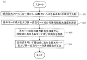
- FIG. 1 is a process diagram illustrating a first optical pulse test method of the present embodiment.
- This optical pulse test method is First injection procedure for injecting a test optical pulse having a wavelength capable of propagating the optical fiber under test in the fundamental mode and the first higher mode in the fundamental mode from one end of the optical fiber under test in which optical fibers of the same type are connected in series S01, First, the return light generated by the test light pulse incident in the first incident step S01 is received, and the intensity distribution regarding the distance from the one end is measured for each of the fundamental mode component and the first higher-order mode component of the return light.
- Measurement procedure S02 From the intensity distribution measured in the first measurement step S02, the loss L1 of the fundamental mode component of the return light and the first higher-order mode component of the return light at the connection point where the optical fibers of the same type of the optical fiber under test are connected in series.
- a first loss calculation step S03 for calculating the loss L2 A formula expressing the loss L1, the loss L2, the transmission loss L01 of the fundamental mode at the connection point, and the transmission loss L11 of the first higher-order mode at the connection point between the modes at the connection point is given by: By substituting the loss L1 and the loss L2 calculated in the first loss calculation step S03 into the equation (8) obtained by the simultaneous equations, the transmission loss L01 of the basic mode and the transmission loss L11 of the first higher mode.
- a first calculation step S04 for calculating It is characterized by performing.
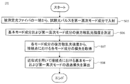
- FIG. 2 is a process diagram illustrating the second optical pulse test method of the present embodiment.
- This optical pulse test method is From one end of the optical fiber under test in which optical fibers of the same kind are connected in series, a test optical pulse having a wavelength capable of propagating the optical fiber under test in the fundamental mode and the first higher order mode is incident in the first higher order mode.
- Two-injection procedure S05, Second the return light generated by the test light pulse incident in the second incidence step S05 is received, and the intensity distribution regarding the distance from the one end is measured for each of the fundamental mode component and the first higher-order mode component of the return light.
- Measurement procedure S06 From the intensity distribution measured in the second measurement procedure S06, the loss L3 of the fundamental mode component of the return light and the first higher-order mode component of the return light at the connection point where the optical fibers of the same kind of the optical fiber under test are connected in series.
- a second loss calculation step S07 for calculating the loss L4, Formulas of the loss L3, the loss L4, the transmission loss L01 of the fundamental mode at the connection point, and the transmission loss L11 of the first higher-order mode at the connection point expressed by the coupling efficiency between the modes at the connection point are shown below.
- a second calculation step S08 for calculating It is characterized by performing.
- a first calculation step for calculating the transmission loss in the fundamental mode and the first higher-order mode at the connection point is performed from the loss acquired in the first loss calculation step using an approximate expression (equation (8)). Details of calculating the transmission loss in the fundamental mode and the first higher-order mode at the connection point will be described later.
- a second calculation step for calculating the transmission loss in the basic mode and the first higher-order mode at the connection point is performed from the loss acquired in the second loss calculation step using an approximate expression (equation (9)). Details of calculating the transmission loss in the fundamental mode and the first higher-order mode at the connection point will be described later.
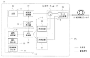
- FIG. 3 is a diagram illustrating a configuration example of the optical pulse test apparatus 101 that performs the first and second optical pulse test methods.
- the optical pulse test apparatus 101 First incidence of a test optical pulse having a wavelength capable of propagating in the optical fiber under test 10 in the fundamental mode and the first higher mode in the fundamental mode from one end of the optical fiber under test 10 in which optical fibers of the same type are connected in series Means and First, the return light generated by the test light pulse that is incident by the first incidence unit is received, and an intensity distribution regarding a distance from the one end is measured for each of a fundamental mode component and a first higher-order mode component of the return light.
- Measuring means From the intensity distribution measured by the first measuring means, the loss L1 of the fundamental mode component of the return light and the first higher-order mode component of the return light at the connection point where the optical fibers of the same type of the optical fiber under test 10 are connected in series.
- First loss calculating means for calculating the loss L2 A formula expressing the loss L1, the loss L2, the transmission loss L01 of the fundamental mode at the connection point, and the transmission loss L11 of the first higher-order mode at the connection point between the modes at the connection point is given by: Substituting the loss L1 and the loss L2 calculated by the first loss calculating means into the formula (8) obtained by the simultaneous equations, the transmission loss L01 of the basic mode and the transmission loss L11 of the first higher mode.
- a first calculation means for calculating It is characterized by including.
- the optical pulse test apparatus 101 Second incidence means for injecting a test optical pulse having a wavelength capable of propagating the optical fiber under test 10 in the fundamental mode and the first higher order mode from one end of the optical fiber under test 10 in the first higher order mode
- the second incident means receives the return light generated by the test light pulse incident, and measures the intensity distribution with respect to the distance from the one end for each of the fundamental mode component and the first higher-order mode component of the return light.
- Measuring means Based on the intensity distribution measured by the second measuring means, the loss L3 of the fundamental mode component of the return light and the first higher-order mode component of the return light at the connection point where the optical fibers of the same kind of the optical fiber under test 10 are connected in series.
- Second loss calculating means for calculating the loss L4, Formulas of the loss L3, the loss L4, the transmission loss L01 of the fundamental mode at the connection point, and the transmission loss L11 of the first higher-order mode at the connection point expressed by the coupling efficiency between the modes at the connection point are shown below. Substituting the loss L3 and the loss L4 calculated by the second loss calculating means into the equation (9) obtained by the simultaneous equations, the transmission loss L01 of the basic mode and the transmission loss L11 of the first higher mode.
- a second calculation means for calculating It is characterized by including.
- the first incident means and the second incident means A generation unit A for generating a test light pulse having a wavelength capable of propagating through the optical fiber under test 10 in the fundamental mode and the first higher order mode;
- the test light pulse generated by the generation unit A is incident on the optical fiber under test 10 in either the fundamental mode or the first higher-order mode, and the return light from the test light pulse is changed to the fundamental mode and the first higher-order mode.
- a mode combining/branching unit B to be separated, Composed of.
- the first measuring means and the second measuring means Mode combining/branching unit B, A light receiving section C for photoelectrically converting each of the mode components of the return light separated by the mode multiplexing/demultiplexing section B;
- an A/D (analog/digital) converter 18 for converting the output signal of the light receiving section C into digital data, and the distance from the one end of the optical fiber 10 under test based on the digital data.
- a signal processing unit 19 for acquiring the intensity distribution of each mode component of the return light, Composed of.
- the first calculation means and the second calculation means In the arithmetic processing unit D, the transmission loss calculation unit 21 that calculates the transmission loss of each mode from the loss calculated by the loss calculation unit 20. Composed of.
- the generator A has a light source 11, a pulse generator 12, and a light intensity modulator 13.
- the light source 11 can output continuous light having a wavelength that can propagate through the optical fiber under test 10 in the fundamental mode and the first higher-order mode, and the output continuous light is output by the light intensity modulator 13 according to the signal from the pulse generator 12.
- the test light pulse is pulsed.
- the light intensity modulator 13 is an acousto-optic modulator including, for example, an acousto-optic switch configured to pulse-drive an acousto-optic element.
- the pulse generator 12 may output to the arithmetic processing unit D a trigger signal for determining the timing to start the measurement of the backscattered light intensity distribution.
- the mode multiplexer/demultiplexer B has an optical circulator 14 and a mode multiplexer/demultiplexer 15.
- the test light pulse generated by the light intensity modulator 13 is incident on the mode multiplexer/demultiplexer 15 via the optical circulator 14.
- the mode multiplexer/demultiplexer 15 is a mode multiplexer/demultiplexer including a directional coupler configured by a planar lightwave circuit as described in Non-Patent Document 2, for example.
- the test light pulse is incident on one end of the optical fiber under test 10 from the mode multiplexer/demultiplexer 15 as a fundamental mode or a first higher order mode.
- test light pulse incident in the fundamental mode or the first higher-order mode propagates through the optical fiber under test 10
- a part of the test light pulse propagates in the opposite direction due to Rayleigh scattering into the fundamental mode and the first higher-order mode. Combined, they become the backscattered light of the fundamental mode and the first higher mode, respectively.
- This backscattered light is re-incident on the mode multiplexer/demultiplexer 15 as return light.
- the mode components of the return light fundamental mode and the first higher-order mode are separated by the mode multiplexer/demultiplexer 15.
- the light receiving section C has two optical receivers (16, 17). Of the return light separated for each mode by the mode multiplexer/demultiplexer 15, the fundamental mode component is incident on the optical receiver 16 via the optical circulator 14, and the first higher-order mode component is incident on the optical receiver 17. It is photoelectrically converted.
- the arithmetic processing unit D has an A/D converter 18, a signal processing unit 19, a loss calculation unit 20, and a transmission loss calculation unit 21.
- the electric signals from the optical receivers 16 and 17 are converted into digital data by the A/D converter 18.
- the digital data is input to the signal processing unit 19.
- the signal processing unit 19 acquires the intensity distribution for the fundamental mode and the first higher-order mode component of the returning light. Furthermore, the loss calculation unit 20 acquires the loss occurring in the intensity distribution for the fundamental mode and the first higher-order mode component of the return light at the connection point. Then, the transmission loss calculation unit 21 performs arithmetic processing to calculate the transmission loss of each mode at the connection point.
- the arithmetic processing unit D can also be realized by a computer and a program, and the program can be recorded in a recording medium or provided through a network.
- the loss at the connection point in the backscattered light intensity of the fundamental mode component and the first higher-order mode component can be expressed by the following formula.
- L1 and L2 are connection point losses in the backscattered light intensity of the fundamental mode component and the first higher-order mode component expressed in decibel units, respectively.
- ⁇ 01-01 represents the efficiency of coupling from fundamental mode to fundamental mode at the connection.
- ⁇ 01-11 represents the efficiency of coupling from the fundamental mode to the first higher order mode at the junction.
- ⁇ 11-01 represents the efficiency of coupling from the first higher order mode to the fundamental mode at the junction.
- ⁇ 11-11 represents the coupling efficiency from the first higher order mode to the first higher order mode at the connection.
- ⁇ 01-11 and ⁇ 11-01 are symmetric, Is.
- the loss at the connection point in the backscattered light intensity of the fundamental mode component and the first higher-order mode component shall be expressed by the following formula.
- You can L3 and L4 are connection point losses in the backscattered light intensity of the fundamental mode component and the first higher-order mode component expressed in decibel units, respectively.
- FIG. 3(A) is an example of measurement of a backscattering waveform when a test light pulse is incident in the basic mode, and explains the relationship between L1 and L2.
- FIG. 3B is a measurement example of the backscattering waveform when the test light pulse is incident in the first higher-order mode, and illustrates the relationship between L3 and L4.
- the transmission loss when the fundamental mode or the first higher-order mode is incident on the optical fiber under test can be expressed by the following equation.
- L01 and L11 are the transmission loss of the fundamental mode and the first higher-order mode at the connection point expressed in decibel units, respectively.
- the present invention is not limited to the above-described embodiment, and various modifications can be made without departing from the scope of the present invention.
- the present invention is not limited to the upper embodiment as it is, and constituent elements can be modified and embodied without departing from the scope of the invention at the implementation stage.
- the arithmetic processing unit D can be realized by a computer and a program, and the program can be recorded in a recording medium or provided through a network.
- the optical fiber to be tested is the one in which two optical fibers of the same kind are connected in series. It can also be tested as a fiber.
- the measurement accuracy deteriorates at the connection point farther from the test light incident end.
- various inventions can be formed by appropriately combining a plurality of constituent elements disclosed in the above embodiments. For example, some components may be deleted from all the components shown in the embodiment. Furthermore, the constituent elements of different embodiments may be combined appropriately.
- Optical fiber under test 11 Light source 12: Pulse generator 13: Optical intensity modulator 14: Optical circulator 15: Mode multiplexer/demultiplexer 16, 17: Optical receiver 18: A/D converter 19: Signal processor 20: Loss calculation unit 21: Transmission loss calculation unit 101: Optical pulse test apparatus
Landscapes
- Physics & Mathematics (AREA)
- Optics & Photonics (AREA)
- Chemical & Material Sciences (AREA)
- Analytical Chemistry (AREA)
- General Physics & Mathematics (AREA)
- Engineering & Computer Science (AREA)
- Microelectronics & Electronic Packaging (AREA)
- Testing Of Optical Devices Or Fibers (AREA)
Abstract
2モード光ファイバを直列させた接続点における基本モードおよび第一高次モードの透過損失を、入射する試験光のモードを切り替えることなく測定できる光パルス試験方法および光パルス試験装置を提供することを目的とする。 本発明に係る光パルス試験装置は、被試験光ファイバの一端から基本モードと第一高次モードで伝搬可能な波長の試験光パルスを基本モード(または第一高次モード)で入射し、該試験光パルスの戻り光の基本モード成分および第一高次モード成分それぞれの該一端からの距離に関する強度分布を測定し、該強度分布から被試験光ファイバの所望の接続点における戻り光の基本モード成分および第一高次モード成分の損失をそれぞれ求め、式(8)(または式(9))に基づいて該接続点における基本モードおよび第一高次モードの透過損失を算出する。
Description
本開示は、2モード光ファイバを直列に接続している光ファイバの接続損失を測定するための光パルス試験方法および光パルス試験装置に関する。
動画やゲームに代表される大容量コンテンツの増加やスマートフォンの普及に伴い、光ファイバネットワークにおけるトラフィック量は年々増加している。一方で、現在伝送媒体として用いられているシングルモードファイバには、伝送容量の限界が近づいている。将来的なトラフィック増大に対応するための一つの技術として、数モードファイバを用いたモード多重伝送が注目されている。モード多重伝送の実用化を考えると、数モードファイバを用いた光伝送路構築後に、伝送に用いる各モードの損失特性を測定する技術が必要不可欠となる。
伝送路構築後の損失試験方法としては、光時間領域反射測定法(Optical Time Domain Reflectometry、以下OTDRと称する)が著名である。OTDRは、パルス化された試験光を被試験光ファイバ(Fiber Under Test、以下FUTと称する)に入射し、光ファイバ内を伝搬する試験光パルスに由来するレイリー散乱光の後方散乱光やフレネル反射光の強度とラウンドトリップ時間に基づき分布データ(後方散乱波形)を取得する方法および装置である。非特許文献1では、2モードファイバを試験するためのOTDRとして、後方散乱光に含まれる基本モードと第一高次モードを個別に測定するOTDRが開示されている。各モード成分の後方散乱波形から、光ファイバにおける損失情報を取得することができる。
M.Nakazawa et.al.,"Measurement of mode coupling distribution along a few-mode fiber using a synchronous multi-channel OTDR," Opt. Express, vol. 22, no. 25, pp. 31299-31309, 2014.
A.Nakamura et.al.,"Reduction of modal evolution fluctuation in 2-LP mode optical time domain reflectometry," Opt. Express, vol. 25, no. 17, pp. 20727-20736, 2017.
非特許文献1に記載の試験方法で2モードファイバの接続点における基本モードおよび第一高次モードの損失を取得する場合、試験光を基本モードで入射しての測定と、試験光を第一高次モードで入射しての測定と、の合計2回の測定を行う必要がある。これら2回の測定において、入射するモードを切り替えるために、手動で光コネクタを切り替えることや、光スイッチを装置に組み込むこと、が必要となる。すなわち、測定時の手作業が煩雑となることや、測定装置の構成が複雑となることが課題となる。
本発明は、上記事情を鑑みてなされたものであり、2モード光ファイバを直列させた接続点における基本モードおよび第一高次モードの透過損失を、入射する試験光のモードを切り替えることなく測定できる光パルス試験方法および光パルス試験装置を提供することを目的とする。
上記目的を達成するために、本発明に係る光パルス試験方法および光パルス試験装置は、基本モードまたは第一高次モードのいずれか一方のみの試験光パルスを用い、基本モード成分および第一高次モード成分の後方散乱波形に生じるそれぞれの損失に対して算術処理を施すことにより基本モードおよび第一高次モード双方の透過接続損失を算出することとした。
具体的には、本発明に係る第一の光パルス試験方法は、
同種の光ファイバを直列に接続した被試験光ファイバの一端から、前記被試験光ファイバを基本モードと第一高次モードで伝搬可能な波長の試験光パルスを基本モードで入射する第一入射手順と、
前記第一入射手順で入射した前記試験光パルスにより発生した戻り光を受光し、前記戻り光の基本モード成分および第一高次モード成分それぞれについて前記一端からの距離に関する強度分布を測定する第一測定手順と、
前記第一測定手順で測定した前記強度分布から、前記被試験光ファイバの前記同種の光ファイバを直列に接続した接続点における前記戻り光の基本モード成分の損失L1および第一高次モード成分の損失L2を算出する第一損失算出手順と、
前記損失L1、前記損失L2、前記接続点における基本モードの透過損失L01、および前記接続点における第一高次モードの透過損失L11の、前記接続点における各モード間の結合効率で表した数式を連立させることによって得られる第一の数式に、前記第一損失算出手順で算出した前記損失L1および前記損失L2を代入して前記基本モードの透過損失L01および前記第一高次モードの透過損失L11を演算する第一演算手順と、
を行うことを特徴とする。
同種の光ファイバを直列に接続した被試験光ファイバの一端から、前記被試験光ファイバを基本モードと第一高次モードで伝搬可能な波長の試験光パルスを基本モードで入射する第一入射手順と、
前記第一入射手順で入射した前記試験光パルスにより発生した戻り光を受光し、前記戻り光の基本モード成分および第一高次モード成分それぞれについて前記一端からの距離に関する強度分布を測定する第一測定手順と、
前記第一測定手順で測定した前記強度分布から、前記被試験光ファイバの前記同種の光ファイバを直列に接続した接続点における前記戻り光の基本モード成分の損失L1および第一高次モード成分の損失L2を算出する第一損失算出手順と、
前記損失L1、前記損失L2、前記接続点における基本モードの透過損失L01、および前記接続点における第一高次モードの透過損失L11の、前記接続点における各モード間の結合効率で表した数式を連立させることによって得られる第一の数式に、前記第一損失算出手順で算出した前記損失L1および前記損失L2を代入して前記基本モードの透過損失L01および前記第一高次モードの透過損失L11を演算する第一演算手順と、
を行うことを特徴とする。
また、本発明に係る第二の光パルス試験方法は、
同種の光ファイバを直列に接続した被試験光ファイバの一端から、前記被試験光ファイバを基本モードと第一高次モードで伝搬可能な波長の試験光パルスを第一高次モードで入射する第二入射手順と、
前記第二入射手順で入射した前記試験光パルスにより発生した戻り光を受光し、前記戻り光の基本モード成分および第一高次モード成分それぞれについて前記一端からの距離に関する強度分布を測定する第二測定手順と、
前記第二測定手順で測定した前記強度分布から、前記被試験光ファイバの前記同種の光ファイバを直列に接続した接続点における前記戻り光の基本モード成分の損失L3および第一高次モード成分の損失L4を算出する第二損失算出手順と、
前記損失L3、前記損失L4、前記接続点における基本モードの透過損失L01、および前記接続点における第一高次モードの透過損失L11の、前記接続点における各モード間の結合効率で表した数式を連立させることによって得られる第二の数式に、前記第二損失算出手順で算出した前記損失L3および前記損失L4を代入して前記基本モードの透過損失L01および前記第一高次モードの透過損失L11を演算する第二演算手順と、
を行うことを特徴とする。
同種の光ファイバを直列に接続した被試験光ファイバの一端から、前記被試験光ファイバを基本モードと第一高次モードで伝搬可能な波長の試験光パルスを第一高次モードで入射する第二入射手順と、
前記第二入射手順で入射した前記試験光パルスにより発生した戻り光を受光し、前記戻り光の基本モード成分および第一高次モード成分それぞれについて前記一端からの距離に関する強度分布を測定する第二測定手順と、
前記第二測定手順で測定した前記強度分布から、前記被試験光ファイバの前記同種の光ファイバを直列に接続した接続点における前記戻り光の基本モード成分の損失L3および第一高次モード成分の損失L4を算出する第二損失算出手順と、
前記損失L3、前記損失L4、前記接続点における基本モードの透過損失L01、および前記接続点における第一高次モードの透過損失L11の、前記接続点における各モード間の結合効率で表した数式を連立させることによって得られる第二の数式に、前記第二損失算出手順で算出した前記損失L3および前記損失L4を代入して前記基本モードの透過損失L01および前記第一高次モードの透過損失L11を演算する第二演算手順と、
を行うことを特徴とする。
また、本発明に係る第一の光パルス試験装置は、
同種の光ファイバを直列に接続した被試験光ファイバの一端から、前記被試験光ファイバを基本モードと第一高次モードで伝搬可能な波長の試験光パルスを基本モードで入射する第一入射手段と、
前記第一入射手段が入射した前記試験光パルスにより発生した戻り光を受光し、前記戻り光の基本モード成分および第一高次モード成分それぞれについて前記一端からの距離に関する強度分布を測定する第一測定手段と、
前記第一測定手段が測定した前記強度分布から、前記被試験光ファイバの前記同種の光ファイバを直列に接続した接続点における前記戻り光の基本モード成分の損失L1および第一高次モード成分の損失L2を算出する第一損失算出手段と、
前記損失L1、前記損失L2、前記接続点における基本モードの透過損失L01、および前記接続点における第一高次モードの透過損失L11の、前記接続点における各モード間の結合効率で表した数式を連立させることによって得られる第一の数式に、前記第二損失算出手段が算出した前記損失L1および前記損失L2を代入して前記基本モードの透過損失L01および前記第一高次モードの透過損失L11を演算する第一演算手段と、
を備えることを特徴とする。
同種の光ファイバを直列に接続した被試験光ファイバの一端から、前記被試験光ファイバを基本モードと第一高次モードで伝搬可能な波長の試験光パルスを基本モードで入射する第一入射手段と、
前記第一入射手段が入射した前記試験光パルスにより発生した戻り光を受光し、前記戻り光の基本モード成分および第一高次モード成分それぞれについて前記一端からの距離に関する強度分布を測定する第一測定手段と、
前記第一測定手段が測定した前記強度分布から、前記被試験光ファイバの前記同種の光ファイバを直列に接続した接続点における前記戻り光の基本モード成分の損失L1および第一高次モード成分の損失L2を算出する第一損失算出手段と、
前記損失L1、前記損失L2、前記接続点における基本モードの透過損失L01、および前記接続点における第一高次モードの透過損失L11の、前記接続点における各モード間の結合効率で表した数式を連立させることによって得られる第一の数式に、前記第二損失算出手段が算出した前記損失L1および前記損失L2を代入して前記基本モードの透過損失L01および前記第一高次モードの透過損失L11を演算する第一演算手段と、
を備えることを特徴とする。
また、本発明に係る第二の光パルス試験装置は、
同種の光ファイバを直列に接続した被試験光ファイバの一端から、前記被試験光ファイバを基本モードと第一高次モードで伝搬可能な波長の試験光パルスを第一高次モードで入射する第二入射手段と、
前記第二入射手段が入射した前記試験光パルスにより発生した戻り光を受光し、前記戻り光の基本モード成分および第一高次モード成分それぞれについて前記一端からの距離に関する強度分布を測定する第二測定手段と、
前記第二測定手段が測定した前記強度分布から、前記被試験光ファイバの前記同種の光ファイバを直列に接続した接続点における前記戻り光の基本モード成分の損失L3および第一高次モード成分の損失L4を算出する第二損失算出手段と、
前記損失L3、前記損失L4、前記接続点における基本モードの透過損失L01、および前記接続点における第一高次モードの透過損失L11の、前記接続点における各モード間の結合効率で表した数式を連立させることによって得られる第二の数式に、前記第一損失算出手段が算出した前記損失L3および前記損失L4を代入して前記基本モードの透過損失L01および前記第一高次モードの透過損失L11を演算する第二演算手段と、
を備えることを特徴とする。
同種の光ファイバを直列に接続した被試験光ファイバの一端から、前記被試験光ファイバを基本モードと第一高次モードで伝搬可能な波長の試験光パルスを第一高次モードで入射する第二入射手段と、
前記第二入射手段が入射した前記試験光パルスにより発生した戻り光を受光し、前記戻り光の基本モード成分および第一高次モード成分それぞれについて前記一端からの距離に関する強度分布を測定する第二測定手段と、
前記第二測定手段が測定した前記強度分布から、前記被試験光ファイバの前記同種の光ファイバを直列に接続した接続点における前記戻り光の基本モード成分の損失L3および第一高次モード成分の損失L4を算出する第二損失算出手段と、
前記損失L3、前記損失L4、前記接続点における基本モードの透過損失L01、および前記接続点における第一高次モードの透過損失L11の、前記接続点における各モード間の結合効率で表した数式を連立させることによって得られる第二の数式に、前記第一損失算出手段が算出した前記損失L3および前記損失L4を代入して前記基本モードの透過損失L01および前記第一高次モードの透過損失L11を演算する第二演算手段と、
を備えることを特徴とする。
ここで、前記損失L1、前記損失L2、前記基本モードの透過損失L01、および前記第一高次モードの透過損失L11をデシベル単位で表記し、前記第一の数式として式(C1)を用いる。

また、前記損失L3、前記損失L4、前記基本モードの透過損失L01、および前記第一高次モードの透過損失L11をデシベル単位で表記し、前記第二の数式として式(C2)を用いる。

本発明は、2モード光ファイバを直列させた接続点における基本モードおよび第一高次モードの透過損失を、入射する試験光のモードを切り替えることなく測定できる光パルス試験方法および光パルス試験装置を提供することができる。
添付の図面を参照して本発明の実施形態を説明する。以下に説明する実施形態は本発明の実施例であり、本発明は以下の実施形態に制限されるものではない。なお、本明細書および図面において、符号が同じ構成要素は相互に同一のものを示すものとする。
図1は、本実施形態の第一の光パルス試験方法を説明する工程図である。本光パルス試験方法は、
同種の光ファイバを直列に接続した被試験光ファイバの一端から、前記被試験光ファイバを基本モードと第一高次モードで伝搬可能な波長の試験光パルスを基本モードで入射する第一入射手順S01と、
第一入射手順S01で入射した前記試験光パルスにより発生した戻り光を受光し、前記戻り光の基本モード成分および第一高次モード成分それぞれについて前記一端からの距離に関する強度分布を測定する第一測定手順S02と、
第一測定手順S02で測定した前記強度分布から、前記被試験光ファイバの前記同種の光ファイバを直列に接続した接続点における前記戻り光の基本モード成分の損失L1および第一高次モード成分の損失L2を算出する第一損失算出手順S03と、
前記損失L1、前記損失L2、前記接続点における基本モードの透過損失L01、および前記接続点における第一高次モードの透過損失L11の、前記接続点における各モード間の結合効率で表した数式を連立させることによって得られる式(8)に、第一損失算出手順S03で算出した前記損失L1および前記損失L2を代入して前記基本モードの透過損失L01および前記第一高次モードの透過損失L11を演算する第一演算手順S04と、
を行うことを特徴とする。
同種の光ファイバを直列に接続した被試験光ファイバの一端から、前記被試験光ファイバを基本モードと第一高次モードで伝搬可能な波長の試験光パルスを基本モードで入射する第一入射手順S01と、
第一入射手順S01で入射した前記試験光パルスにより発生した戻り光を受光し、前記戻り光の基本モード成分および第一高次モード成分それぞれについて前記一端からの距離に関する強度分布を測定する第一測定手順S02と、
第一測定手順S02で測定した前記強度分布から、前記被試験光ファイバの前記同種の光ファイバを直列に接続した接続点における前記戻り光の基本モード成分の損失L1および第一高次モード成分の損失L2を算出する第一損失算出手順S03と、
前記損失L1、前記損失L2、前記接続点における基本モードの透過損失L01、および前記接続点における第一高次モードの透過損失L11の、前記接続点における各モード間の結合効率で表した数式を連立させることによって得られる式(8)に、第一損失算出手順S03で算出した前記損失L1および前記損失L2を代入して前記基本モードの透過損失L01および前記第一高次モードの透過損失L11を演算する第一演算手順S04と、
を行うことを特徴とする。
また、図2は、本実施形態の第二の光パルス試験方法を説明する工程図である。本光パルス試験方法は、
同種の光ファイバを直列に接続した被試験光ファイバの一端から、前記被試験光ファイバを基本モードと第一高次モードで伝搬可能な波長の試験光パルスを第一高次モードで入射する第二入射手順S05と、
第二入射手順S05で入射した前記試験光パルスにより発生した戻り光を受光し、前記戻り光の基本モード成分および第一高次モード成分それぞれについて前記一端からの距離に関する強度分布を測定する第二測定手順S06と、
第二測定手順S06で測定した前記強度分布から、前記被試験光ファイバの前記同種の光ファイバを直列に接続した接続点における前記戻り光の基本モード成分の損失L3および第一高次モード成分の損失L4を算出する第二損失算出手順S07と、
前記損失L3、前記損失L4、前記接続点における基本モードの透過損失L01、および前記接続点における第一高次モードの透過損失L11の、前記接続点における各モード間の結合効率で表した数式を連立させることによって得られる式(9)に、第二損失算出手順S07で算出した前記損失L3および前記損失L4を代入して前記基本モードの透過損失L01および前記第一高次モードの透過損失L11を演算する第二演算手順S08と、
を行うことを特徴とする。
同種の光ファイバを直列に接続した被試験光ファイバの一端から、前記被試験光ファイバを基本モードと第一高次モードで伝搬可能な波長の試験光パルスを第一高次モードで入射する第二入射手順S05と、
第二入射手順S05で入射した前記試験光パルスにより発生した戻り光を受光し、前記戻り光の基本モード成分および第一高次モード成分それぞれについて前記一端からの距離に関する強度分布を測定する第二測定手順S06と、
第二測定手順S06で測定した前記強度分布から、前記被試験光ファイバの前記同種の光ファイバを直列に接続した接続点における前記戻り光の基本モード成分の損失L3および第一高次モード成分の損失L4を算出する第二損失算出手順S07と、
前記損失L3、前記損失L4、前記接続点における基本モードの透過損失L01、および前記接続点における第一高次モードの透過損失L11の、前記接続点における各モード間の結合効率で表した数式を連立させることによって得られる式(9)に、第二損失算出手順S07で算出した前記損失L3および前記損失L4を代入して前記基本モードの透過損失L01および前記第一高次モードの透過損失L11を演算する第二演算手順S08と、
を行うことを特徴とする。
第一入射手順S01では、
被試験光ファイバを基本モードと第一高次モードで伝搬可能な波長の試験光パルスを生成する生成ステップと、
前記生成ステップで生成した前記試験光パルスを基本モードで前記被試験光ファイバの一端に入射する第一入射ステップと、
を行う。
被試験光ファイバを基本モードと第一高次モードで伝搬可能な波長の試験光パルスを生成する生成ステップと、
前記生成ステップで生成した前記試験光パルスを基本モードで前記被試験光ファイバの一端に入射する第一入射ステップと、
を行う。
第一測定手順S02では、
前記第一入射ステップで前記被試験光ファイバの一端に入射した前記試験光パルスの戻り光を基本モードおよび第一高次モードに分離するモード分波ステップと、
前記モード分波ステップで分離した前記戻り光のモード成分それぞれを光電変換し、前記被試験光ファイバ一端からの距離に対する前記戻り光のモード成分それぞれの強度分布を取得する第一光強度取得ステップと、
を行う。つまり、第一入射手順S01と第一測定手順S02で非特許文献1および非特許文献2に示されるような後方散乱光測定技術を用いて、被試験光ファイバの一端から基本モードおよび第一高次モードの後方散乱光強度分布を測定する。
前記第一入射ステップで前記被試験光ファイバの一端に入射した前記試験光パルスの戻り光を基本モードおよび第一高次モードに分離するモード分波ステップと、
前記モード分波ステップで分離した前記戻り光のモード成分それぞれを光電変換し、前記被試験光ファイバ一端からの距離に対する前記戻り光のモード成分それぞれの強度分布を取得する第一光強度取得ステップと、
を行う。つまり、第一入射手順S01と第一測定手順S02で非特許文献1および非特許文献2に示されるような後方散乱光測定技術を用いて、被試験光ファイバの一端から基本モードおよび第一高次モードの後方散乱光強度分布を測定する。
第一損失算出手順S03では、
前記第一光強度取得ステップで取得した前記戻り光のモード成分それぞれの強度分布から前記被試験光ファイバの接続点における前記戻り光のモード成分に生じた損失を算出する第一損失算出ステップ
を行う。
前記第一光強度取得ステップで取得した前記戻り光のモード成分それぞれの強度分布から前記被試験光ファイバの接続点における前記戻り光のモード成分に生じた損失を算出する第一損失算出ステップ
を行う。
第一演算手順S04では、
前記第一損失算出ステップで取得した損失から近似式(式(8))を用いて接続点における基本モードおよび第一高次モードの透過損失を演算する第一演算ステップ
を行う。接続点における基本モードおよび第一高次モードの透過損失を演算する詳細は後述する。
前記第一損失算出ステップで取得した損失から近似式(式(8))を用いて接続点における基本モードおよび第一高次モードの透過損失を演算する第一演算ステップ
を行う。接続点における基本モードおよび第一高次モードの透過損失を演算する詳細は後述する。
第二入射手順S05では、
被試験光ファイバを基本モードと第一高次モードで伝搬可能な波長の試験光パルスを生成する生成ステップと、
前記生成ステップで生成した前記試験光パルスを第一高次モードで前記被試験光ファイバの一端に入射する第二入射ステップと、
を行う。
被試験光ファイバを基本モードと第一高次モードで伝搬可能な波長の試験光パルスを生成する生成ステップと、
前記生成ステップで生成した前記試験光パルスを第一高次モードで前記被試験光ファイバの一端に入射する第二入射ステップと、
を行う。
第二測定手順S06では、
前記第二入射ステップで前記被試験光ファイバの一端に入射した前記試験光パルスの戻り光を基本モードおよび第一高次モードに分離するモード分波ステップと、
前記モード分波ステップで分離した前記戻り光のモード成分それぞれを光電変換し、前記被試験光ファイバ一端からの距離に対する前記戻り光のモード成分それぞれの強度分布を取得する第二光強度取得ステップと、
を行う。つまり、第二入射手順S05と第二測定手順S06で非特許文献1および非特許文献2に示されるような後方散乱光測定技術を用いて、被試験光ファイバの一端から基本モードおよび第一高次モードの後方散乱光強度分布を測定する。
前記第二入射ステップで前記被試験光ファイバの一端に入射した前記試験光パルスの戻り光を基本モードおよび第一高次モードに分離するモード分波ステップと、
前記モード分波ステップで分離した前記戻り光のモード成分それぞれを光電変換し、前記被試験光ファイバ一端からの距離に対する前記戻り光のモード成分それぞれの強度分布を取得する第二光強度取得ステップと、
を行う。つまり、第二入射手順S05と第二測定手順S06で非特許文献1および非特許文献2に示されるような後方散乱光測定技術を用いて、被試験光ファイバの一端から基本モードおよび第一高次モードの後方散乱光強度分布を測定する。
第一損失算出手順S07では、
前記第二光強度取得ステップで取得した前記戻り光のモード成分それぞれの強度分布から前記被試験光ファイバの接続点における前記戻り光のモード成分に生じた損失を算出する第二損失算出ステップ
を行う。
前記第二光強度取得ステップで取得した前記戻り光のモード成分それぞれの強度分布から前記被試験光ファイバの接続点における前記戻り光のモード成分に生じた損失を算出する第二損失算出ステップ
を行う。
第二演算手順S08では、
前記第二損失算出ステップで取得した損失から近似式(式(9))を用いて接続点における基本モードおよび第一高次モードの透過損失を演算する第二演算ステップ
を行う。接続点における基本モードおよび第一高次モードの透過損失を演算する詳細は後述する。
前記第二損失算出ステップで取得した損失から近似式(式(9))を用いて接続点における基本モードおよび第一高次モードの透過損失を演算する第二演算ステップ
を行う。接続点における基本モードおよび第一高次モードの透過損失を演算する詳細は後述する。
図3は、第一および第二の光パルス試験方法を行う光パルス試験装置101の構成例を説明する図である。
図1に示した第一の光パルス試験方法を行う場合、光パルス試験装置101は、
同種の光ファイバを直列に接続した被試験光ファイバ10の一端から、被試験光ファイバ10を基本モードと第一高次モードで伝搬可能な波長の試験光パルスを基本モードで入射する第一入射手段と、
前記第一入射手段が入射した前記試験光パルスにより発生した戻り光を受光し、前記戻り光の基本モード成分および第一高次モード成分それぞれについて前記一端からの距離に関する強度分布を測定する第一測定手段と、
前記第一測定手段が測定した前記強度分布から、被試験光ファイバ10の前記同種の光ファイバを直列に接続した接続点における前記戻り光の基本モード成分の損失L1および第一高次モード成分の損失L2を算出する第一損失算出手段と、
前記損失L1、前記損失L2、前記接続点における基本モードの透過損失L01、および前記接続点における第一高次モードの透過損失L11の、前記接続点における各モード間の結合効率で表した数式を連立させることによって得られる式(8)に、前記第一損失算出手段が算出した前記損失L1および前記損失L2を代入して前記基本モードの透過損失L01および前記第一高次モードの透過損失L11を演算する第一演算手段と、
を備えることを特徴とする。
図1に示した第一の光パルス試験方法を行う場合、光パルス試験装置101は、
同種の光ファイバを直列に接続した被試験光ファイバ10の一端から、被試験光ファイバ10を基本モードと第一高次モードで伝搬可能な波長の試験光パルスを基本モードで入射する第一入射手段と、
前記第一入射手段が入射した前記試験光パルスにより発生した戻り光を受光し、前記戻り光の基本モード成分および第一高次モード成分それぞれについて前記一端からの距離に関する強度分布を測定する第一測定手段と、
前記第一測定手段が測定した前記強度分布から、被試験光ファイバ10の前記同種の光ファイバを直列に接続した接続点における前記戻り光の基本モード成分の損失L1および第一高次モード成分の損失L2を算出する第一損失算出手段と、
前記損失L1、前記損失L2、前記接続点における基本モードの透過損失L01、および前記接続点における第一高次モードの透過損失L11の、前記接続点における各モード間の結合効率で表した数式を連立させることによって得られる式(8)に、前記第一損失算出手段が算出した前記損失L1および前記損失L2を代入して前記基本モードの透過損失L01および前記第一高次モードの透過損失L11を演算する第一演算手段と、
を備えることを特徴とする。
また、図2に示した第二の光パルス試験方法を行う場合、光パルス試験装置101は、
被試験光ファイバ10の一端から、被試験光ファイバ10を基本モードと第一高次モードで伝搬可能な波長の試験光パルスを第一高次モードで入射する第二入射手段と、
前記第二入射手段が入射した前記試験光パルスにより発生した戻り光を受光し、前記戻り光の基本モード成分および第一高次モード成分それぞれについて前記一端からの距離に関する強度分布を測定する第二測定手段と、
前記第二測定手段が測定した前記強度分布から、被試験光ファイバ10の前記同種の光ファイバを直列に接続した接続点における前記戻り光の基本モード成分の損失L3および第一高次モード成分の損失L4を算出する第二損失算出手段と、
前記損失L3、前記損失L4、前記接続点における基本モードの透過損失L01、および前記接続点における第一高次モードの透過損失L11の、前記接続点における各モード間の結合効率で表した数式を連立させることによって得られる式(9)に、前記第二損失算出手段が算出した前記損失L3および前記損失L4を代入して前記基本モードの透過損失L01および前記第一高次モードの透過損失L11を演算する第二演算手段と、
を備えることを特徴とする。
被試験光ファイバ10の一端から、被試験光ファイバ10を基本モードと第一高次モードで伝搬可能な波長の試験光パルスを第一高次モードで入射する第二入射手段と、
前記第二入射手段が入射した前記試験光パルスにより発生した戻り光を受光し、前記戻り光の基本モード成分および第一高次モード成分それぞれについて前記一端からの距離に関する強度分布を測定する第二測定手段と、
前記第二測定手段が測定した前記強度分布から、被試験光ファイバ10の前記同種の光ファイバを直列に接続した接続点における前記戻り光の基本モード成分の損失L3および第一高次モード成分の損失L4を算出する第二損失算出手段と、
前記損失L3、前記損失L4、前記接続点における基本モードの透過損失L01、および前記接続点における第一高次モードの透過損失L11の、前記接続点における各モード間の結合効率で表した数式を連立させることによって得られる式(9)に、前記第二損失算出手段が算出した前記損失L3および前記損失L4を代入して前記基本モードの透過損失L01および前記第一高次モードの透過損失L11を演算する第二演算手段と、
を備えることを特徴とする。
前記第一入射手段および前記第二入射手段は、
被試験光ファイバ10を基本モードおよび第一高次モードで伝搬可能な波長の試験光パルスを生成する生成部Aと、
生成部Aが生成した試験光パルスを基本モードまたは第一高次モードのいずれかで被試験光ファイバ10に入射し、かつ前記試験光パルスからの戻り光を基本モードおよび第一高次モードに分離するモード合分波部Bと、
で構成される。
被試験光ファイバ10を基本モードおよび第一高次モードで伝搬可能な波長の試験光パルスを生成する生成部Aと、
生成部Aが生成した試験光パルスを基本モードまたは第一高次モードのいずれかで被試験光ファイバ10に入射し、かつ前記試験光パルスからの戻り光を基本モードおよび第一高次モードに分離するモード合分波部Bと、
で構成される。
前記第一測定手段および第二測定手段は、
モード合分波部Bと、
モード合分波部Bが分離した前記戻り光のモード成分それぞれを光電変換する受光部Cと、
演算処理部Dのうち、受光部Cの出力信号をデジタルデータに変換するA/D(アナログ/デジタル)変換器18と、前記デジタルデータに基づいて被試験光ファイバ10の一端からの距離に対する前記戻り光のモード成分それぞれの強度分布を取得する信号処理部19と、
で構成される。
モード合分波部Bと、
モード合分波部Bが分離した前記戻り光のモード成分それぞれを光電変換する受光部Cと、
演算処理部Dのうち、受光部Cの出力信号をデジタルデータに変換するA/D(アナログ/デジタル)変換器18と、前記デジタルデータに基づいて被試験光ファイバ10の一端からの距離に対する前記戻り光のモード成分それぞれの強度分布を取得する信号処理部19と、
で構成される。
前記第一損失算出手段および前記第二損失算出手段は、
演算処理部Dのうち、前記戻り光のモード成分それぞれの強度分布から接続点で生じた損失を算出する損失算出部20
で構成される。
演算処理部Dのうち、前記戻り光のモード成分それぞれの強度分布から接続点で生じた損失を算出する損失算出部20
で構成される。
前記第一演算手段および前記第二演算手段は、
演算処理部Dのうち、損失算出部20が算出した損失から各モードの透過損失を算出する透過損失算出部21
で構成される。
演算処理部Dのうち、損失算出部20が算出した損失から各モードの透過損失を算出する透過損失算出部21
で構成される。
生成部Aは、光源11、パルス発生器12および光強度変調器13を有する。光源11は被試験光ファイバ10を基本モードおよび第一高次モードで伝搬可能な波長の連続光を出力可能であり、出力される連続光はパルス発生器12の信号に従って光強度変調器13でパルス化され、試験光パルスとなる。光強度変調器13は、例えば音響光学素子をパルス駆動するようにした音響光学スイッチを備える、音響光学変調器である。なお、パルス発生器12は、演算処理部Dに対して、後方散乱光強度分布の測定を開始するタイミングを決めるためのトリガ信号を出力するようにしてもよい。
モード合分波部Bは、光サーキュレータ14およびモード合分波器15を有する。光強度変調器13で生成された試験光パルスは、光サーキュレータ14を介してモード合分波器15に入射される。モード合分波器15は、例えば非特許文献2に記載されるような平面光波回路で構成された方向性結合器を備える、モード合分波器である。試験光パルスは、モード合分波器15から基本モードまたは第一高次モードとして被試験光ファイバ10の一端に入射される。
基本モードまたは第一高次モードで入射された試験光パルスが被試験光ファイバ10を伝搬する際、レイリー散乱によって試験光パルスの一部は逆方向に伝搬する基本モードおよび第一高次モードに結合し、それぞれ基本モードおよび第一高次モードの後方散乱光となる。この後方散乱光は、戻り光としてモード合分波器15に再入射される。このとき戻り光の基本モードと第一高次モードのモード成分はモード合分波器15で分離される。
受光部Cは、2つの光受信器(16、17)を有する。モード合分波器15でモード毎に分離された戻り光のうち、基本モード成分は光サーキュレータ14を経由して光受信器16に、第一高次モード成分は光受信器17に入射され、光電変換される。
演算処理部Dは、A/D変換器18、信号処理部19、損失算出部20、透過損失算出部21を有する。光受信器16および17からの電気信号は、A/D変換器18でデジタルデータに変換される。前記デジタルデータは信号処理部19に入力される。
信号処理部19は、戻り光の基本モードと第一高次モード成分に対する強度分布を取得する。さらに、損失算出部20は、接続点において戻り光の基本モードと第一高次モード成分に対する強度分布に生じる損失を取得する。そして、透過損失算出部21は、接続点における各モードの透過損失を算出する演算処理を行う。
なお、演算処理部Dはコンピュータとプログラムによっても実現でき、プログラムを記録媒体に記録することも、ネットワークを通して提供することも可能である。
以下、接続点における基本モードおよび第一高次モードの透過損失を算出する演算処理について説明する。
被試験光ファイバに基本モードで試験光パルスを入射したときに、基本モード成分および第一高次モード成分の後方散乱光強度における接続点の損失は、以下の式で表すことができる。


L1およびL2はそれぞれ、デシベル単位で表記された基本モード成分および第一高次モード成分の後方散乱光強度における接続点の損失である。
η01-01は、接続部において基本モードから基本モードへ結合する効率を表す。
η01-11は、接続部において基本モードから第一高次モードへ結合する効率を表す。
η11-01は、接続部において第一高次モードから基本モードへ結合する効率を表す。
η11-11は、接続部において第一高次モードから第一高次モードへ結合する効率を表す。
η01-01は、接続部において基本モードから基本モードへ結合する効率を表す。
η01-11は、接続部において基本モードから第一高次モードへ結合する効率を表す。
η11-01は、接続部において第一高次モードから基本モードへ結合する効率を表す。
η11-11は、接続部において第一高次モードから第一高次モードへ結合する効率を表す。
ここで、η01-11とη11-01は対称性より、

である。
また、被試験光ファイバに第一高次モードで試験光パルスを入射したときに、基本モード成分および第一高次モード成分の後方散乱光強度における接続点の損失は、以下の式で表すことができる。


L3およびL4はそれぞれ、デシベル単位で表記された基本モード成分および第一高次モード成分の後方散乱光強度における接続点の損失である。
図3(A)は、基本モードで試験光パルスを入射したときの後方散乱波形の測定例であり、L1とL2の関係を説明している。図3(B)は、第一高次モードで試験光パルスを入射したときの後方散乱波形の測定例であり、L3とL4の関係を説明している。
一方、被試験光ファイバに基本モードまたは第一高次モードを入射したときの透過損失は、以下の式で表すことができる。


L01およびL11はそれぞれ、デシベル単位で表記された接続点における基本モードおよび第一高次モードの透過損失である。
式(1)~(3)、(6)、(7)より、以下の式が得られる。

したがって、式(8)を用いて、測定したL1およびL2から接続点における基本モードおよび第一高次モードの透過損失を算出することができる。
また、式(3)~(7)より、以下の式が得られる。

したがって、式(9)を用いて、測定したL3およびL4から接続点における基本モードおよび第一高次モードの透過損失を算出することができる。
また、式(3)~(7)より、以下の式が得られる。
(他の実施形態)
この発明は上記実施形態に限定されるものではなく、この発明の要旨を逸脱しない範囲で種々変形して実施可能である。
要するにこの発明は、上位実施形態そのままに限定されるものではなく、実施段階ではその要旨を逸脱しない範囲で構成要素を変形して具体化できる。例えば、演算処理部Dは、コンピュータとプログラムによっても実現でき、プログラムを記録媒体に記録することも、ネットワークを通して提供することも可能である。
この発明は上記実施形態に限定されるものではなく、この発明の要旨を逸脱しない範囲で種々変形して実施可能である。
要するにこの発明は、上位実施形態そのままに限定されるものではなく、実施段階ではその要旨を逸脱しない範囲で構成要素を変形して具体化できる。例えば、演算処理部Dは、コンピュータとプログラムによっても実現でき、プログラムを記録媒体に記録することも、ネットワークを通して提供することも可能である。
また、上記実施例では、2本の同種光ファイバを直列に接続したものを被試験光ファイバとして説明したが、3本以上の同種光ファイバまたは異種光ファイバを直列に接続したものを被試験光ファイバとしても試験可能である。ただし、試験光入射端から離れた接続点ほど測定精度に劣化が生じる点について注意が必要である。
また、上記実施形態に開示されている複数の構成要素を適宜な組み合わせにより種々の発明を形成できる。例えば、実施形態に示される全構成要素から幾つかの構成要素を削除してもよい。さらに、異なる実施形態に亘る構成要素を適宜組み合わせてもよい。
10:被試験光ファイバ
11:光源
12:パルス発生器
13:光強度変調器
14:光サーキュレータ
15:モード合分波器
16、17:光受信器
18:A/D変換器
19:信号処理部
20:損失算出部
21:透過損失算出部
101:光パルス試験装置
11:光源
12:パルス発生器
13:光強度変調器
14:光サーキュレータ
15:モード合分波器
16、17:光受信器
18:A/D変換器
19:信号処理部
20:損失算出部
21:透過損失算出部
101:光パルス試験装置
Claims (8)
- 同種の光ファイバを直列に接続した被試験光ファイバの一端から、前記被試験光ファイバを基本モードと第一高次モードで伝搬可能な波長の試験光パルスを基本モードで入射する第一入射手順と、
前記第一入射手順で入射した前記試験光パルスにより発生した戻り光を受光し、前記戻り光の基本モード成分および第一高次モード成分それぞれについて前記一端からの距離に関する強度分布を測定する第一測定手順と、
前記第一測定手順で測定した前記強度分布から、前記被試験光ファイバの前記同種の光ファイバを直列に接続した接続点における前記戻り光の基本モード成分の損失L1および第一高次モード成分の損失L2を算出する第一損失算出手順と、
前記損失L1、前記損失L2、前記接続点における基本モードの透過損失L01、および前記接続点における第一高次モードの透過損失L11の、前記接続点における各モード間の結合効率で表した数式を連立させることによって得られる第一の数式に、前記第一損失算出手順で算出した前記損失L1および前記損失L2を代入して前記基本モードの透過損失L01および前記第一高次モードの透過損失L11を演算する第一演算手順と、
を行うことを特徴とする光パルス試験方法。 - 同種の光ファイバを直列に接続した被試験光ファイバの一端から、前記被試験光ファイバを基本モードと第一高次モードで伝搬可能な波長の試験光パルスを第一高次モードで入射する第二入射手順と、
前記第二入射手順で入射した前記試験光パルスにより発生した戻り光を受光し、前記戻り光の基本モード成分および第一高次モード成分それぞれについて前記一端からの距離に関する強度分布を測定する第二測定手順と、
前記第二測定手順で測定した前記強度分布から、前記被試験光ファイバの前記同種の光ファイバを直列に接続した接続点における前記戻り光の基本モード成分の損失L3および第一高次モード成分の損失L4を算出する第二損失算出手順と、
前記損失L3、前記損失L4、前記接続点における基本モードの透過損失L01、および前記接続点における第一高次モードの透過損失L11の、前記接続点における各モード間の結合効率で表した数式を連立させることによって得られる第二の数式に、前記第二損失算出手順で算出した前記損失L3および前記損失L4を代入して前記基本モードの透過損失L01および前記第一高次モードの透過損失L11を演算する第二演算手順と、
を行うことを特徴とする光パルス試験方法。 - 前記損失L1、前記損失L2、前記接続点における基本モードの透過損失L01、および前記第一高次モードの透過損失L11をデシベル単位で表記し、前記第一の数式として式(C1)を用いることを特徴とする請求項1に記載の光パルス試験方法。

- 前記損失L3、前記損失L4、前記基本モードの透過損失L01、および前記第一高次モードの透過損失L11をデシベル単位で表記し、前記第二の数式として式(C2)を用いることを特徴とする請求項2に記載の光パルス試験方法。

- 同種の光ファイバを直列に接続した被試験光ファイバの一端から、前記被試験光ファイバを基本モードと第一高次モードで伝搬可能な波長の試験光パルスを基本モードで入射する第一入射手段と、
前記第一入射手段が入射した前記試験光パルスにより発生した戻り光を受光し、前記戻り光の基本モード成分および第一高次モード成分それぞれについて前記一端からの距離に関する強度分布を測定する第一測定手段と、
前記第一測定手段が測定した前記強度分布から、前記被試験光ファイバの前記同種の光ファイバを直列に接続した接続点における前記戻り光の基本モード成分の損失L1および第一高次モード成分の損失L2を算出する第一損失算出手段と、
前記損失L1、前記損失L2、前記接続点における基本モードの透過損失L01、および前記接続点における第一高次モードの透過損失L11の、前記接続点における各モード間の結合効率で表した数式を連立させることによって得られる第一の数式に、前記第一損失算出手段が算出した前記損失L1および前記損失L2を代入して前記基本モードの透過損失L01および前記第一高次モードの透過損失L11を演算する第一演算手段と、
を備えることを特徴とする光パルス試験装置。 - 同種の光ファイバを直列に接続した被試験光ファイバの一端から、前記被試験光ファイバを基本モードと第一高次モードで伝搬可能な波長の試験光パルスを第一高次モードで入射する第二入射手段と、
前記第二入射手段が入射した前記試験光パルスにより発生した戻り光を受光し、前記戻り光の基本モード成分および第一高次モード成分それぞれについて前記一端からの距離に関する強度分布を測定する第二測定手段と、
前記第二測定手段が測定した前記強度分布から、前記被試験光ファイバの前記同種の光ファイバを直列に接続した接続点における前記戻り光の基本モード成分の損失L3および第一高次モード成分の損失L4を算出する第二損失算出手段と、
前記損失L3、前記損失L4、前記接続点における基本モードの透過損失L01、および前記接続点における第一高次モードの透過損失L11の、前記接続点における各モード間の結合効率で表した数式を連立させることによって得られる第二の数式に、前記第二損失算出手段が算出した前記損失L3および前記損失L4を代入して前記基本モードの透過損失L01および前記第一高次モードの透過損失L11を演算する第二演算手段と、
を備えることを特徴とする光パルス試験装置。 - 前記損失L1、前記損失L2、前記接続点における基本モードの透過損失L01、および前記第一高次モードの透過損失L11をデシベル単位で表記し、前記第一の数式として式(C1)を用いることを特徴とする請求項5に記載の光パルス試験装置。

- 前記損失L3、前記損失L4、前記基本モードの透過損失L01、および前記第一高次モードの透過損失L11をデシベル単位で表記し、前記第二の数式として式(C2)を用いることを特徴とする請求項6に記載の光パルス試験装置。

Priority Applications (1)
| Application Number | Priority Date | Filing Date | Title |
|---|---|---|---|
| US17/413,880 US11598692B2 (en) | 2018-12-17 | 2019-12-03 | Optical pulse testing method and optical pulse testing device |
Applications Claiming Priority (2)
| Application Number | Priority Date | Filing Date | Title |
|---|---|---|---|
| JP2018-235878 | 2018-12-17 | ||
| JP2018235878A JP7081471B2 (ja) | 2018-12-17 | 2018-12-17 | 光パルス試験方法および光パルス試験装置 |
Publications (1)
| Publication Number | Publication Date |
|---|---|
| WO2020129615A1 true WO2020129615A1 (ja) | 2020-06-25 |
Family
ID=71101409
Family Applications (1)
| Application Number | Title | Priority Date | Filing Date |
|---|---|---|---|
| PCT/JP2019/047195 Ceased WO2020129615A1 (ja) | 2018-12-17 | 2019-12-03 | 光パルス試験方法および光パルス試験装置 |
Country Status (3)
| Country | Link |
|---|---|
| US (1) | US11598692B2 (ja) |
| JP (1) | JP7081471B2 (ja) |
| WO (1) | WO2020129615A1 (ja) |
Families Citing this family (2)
| Publication number | Priority date | Publication date | Assignee | Title |
|---|---|---|---|---|
| JP7081471B2 (ja) * | 2018-12-17 | 2022-06-07 | 日本電信電話株式会社 | 光パルス試験方法および光パルス試験装置 |
| WO2020250310A1 (ja) * | 2019-06-11 | 2020-12-17 | 日本電信電話株式会社 | 光パルス試験方法及び光パルス試験装置 |
Citations (1)
| Publication number | Priority date | Publication date | Assignee | Title |
|---|---|---|---|---|
| JP2018063214A (ja) * | 2016-10-14 | 2018-04-19 | 日本電信電話株式会社 | 2モード光ファイバ特性解析方法および2モード光ファイバ特性解析装置 |
Family Cites Families (2)
| Publication number | Priority date | Publication date | Assignee | Title |
|---|---|---|---|---|
| JP7081471B2 (ja) * | 2018-12-17 | 2022-06-07 | 日本電信電話株式会社 | 光パルス試験方法および光パルス試験装置 |
| WO2020250310A1 (ja) * | 2019-06-11 | 2020-12-17 | 日本電信電話株式会社 | 光パルス試験方法及び光パルス試験装置 |
-
2018
- 2018-12-17 JP JP2018235878A patent/JP7081471B2/ja active Active
-
2019
- 2019-12-03 WO PCT/JP2019/047195 patent/WO2020129615A1/ja not_active Ceased
- 2019-12-03 US US17/413,880 patent/US11598692B2/en active Active
Patent Citations (1)
| Publication number | Priority date | Publication date | Assignee | Title |
|---|---|---|---|---|
| JP2018063214A (ja) * | 2016-10-14 | 2018-04-19 | 日本電信電話株式会社 | 2モード光ファイバ特性解析方法および2モード光ファイバ特性解析装置 |
Non-Patent Citations (1)
| Title |
|---|
| LIU ET AL.: "Simultaneous measurement of mode dependent loss and mode coupling in few mode fibers by analyzing the Rayleigh backscattering amplitudes", APPLIED OPTICS, vol. 57, no. 30, October 2018 (2018-10-01), pages 8894 - 8902, XP055720629 * |
Also Published As
| Publication number | Publication date |
|---|---|
| JP2020098127A (ja) | 2020-06-25 |
| US11598692B2 (en) | 2023-03-07 |
| JP7081471B2 (ja) | 2022-06-07 |
| US20220065744A1 (en) | 2022-03-03 |
Similar Documents
| Publication | Publication Date | Title |
|---|---|---|
| JP6338153B2 (ja) | モード結合比率分布測定方法及びモード結合比率分布測定装置 | |
| JP7322960B2 (ja) | 光ファイバ試験方法および光ファイバ試験装置 | |
| JP6777483B2 (ja) | 光ファイバ試験装置及び光ファイバ試験方法 | |
| JP6769944B2 (ja) | モード遅延時間差分布試験方法および試験装置 | |
| JP7070695B2 (ja) | 光ファイバ試験方法及び光ファイバ試験装置 | |
| JP7606697B2 (ja) | 光学特性測定装置及び方法 | |
| JP6393563B2 (ja) | 光ファイバの評価方法及び評価装置 | |
| JP7136348B2 (ja) | 光パルス試験方法及び光パルス試験装置 | |
| US12385806B2 (en) | Power coupling coefficient measuring method and power coupling coefficient measuring device | |
| JP6706186B2 (ja) | 2モード光ファイバ特性解析方法および2モード光ファイバ特性解析装置 | |
| JP2020056905A (ja) | 後方散乱光増幅装置、光パルス試験装置、後方散乱光増幅方法、及び光パルス試験方法 | |
| WO2020129615A1 (ja) | 光パルス試験方法および光パルス試験装置 | |
| JP5993818B2 (ja) | 光線路特性解析装置及び光線路特性解析方法 | |
| JP2020056904A (ja) | 後方散乱光増幅装置、光パルス試験装置、後方散乱光増幅方法、及び光パルス試験方法 | |
| JP7006537B2 (ja) | ラマン利得効率分布試験方法およびラマン利得効率分布試験装置 | |
| JP7786468B2 (ja) | 光伝送路試験装置及び試験方法 | |
| JP6653616B2 (ja) | 光パルス試験方法及び光パルス試験装置 | |
| JP7380892B2 (ja) | 数モードファイバ試験方法及び数モードファイバ試験装置 | |
| JP2018189600A (ja) | 光パルス試験装置及び光パルス試験方法 | |
| JP2017203626A (ja) | 光パルス試験装置および光パルス試験方法 | |
| JP2017072495A (ja) | 試験光合分波器及び光線路試験システム | |
| WO2024038487A1 (ja) | 双方向のクロストークを評価する装置及び方法 | |
| WO2025104782A1 (ja) | 空間モード分散測定装置 | |
| JP6353429B2 (ja) | 光線路損失解析方法及び光線路損失解析装置 | |
| JP2023174509A (ja) | 群遅延特性測定システム及び方法 |
Legal Events
| Date | Code | Title | Description |
|---|---|---|---|
| 121 | Ep: the epo has been informed by wipo that ep was designated in this application |
Ref document number: 19899628 Country of ref document: EP Kind code of ref document: A1 |
|
| NENP | Non-entry into the national phase |
Ref country code: DE |
|
| 122 | Ep: pct application non-entry in european phase |
Ref document number: 19899628 Country of ref document: EP Kind code of ref document: A1 |