WO2020129583A1 - ディスクブレーキ及びピストンブーツ - Google Patents
ディスクブレーキ及びピストンブーツ Download PDFInfo
- Publication number
- WO2020129583A1 WO2020129583A1 PCT/JP2019/046961 JP2019046961W WO2020129583A1 WO 2020129583 A1 WO2020129583 A1 WO 2020129583A1 JP 2019046961 W JP2019046961 W JP 2019046961W WO 2020129583 A1 WO2020129583 A1 WO 2020129583A1
- Authority
- WO
- WIPO (PCT)
- Prior art keywords
- piston
- diameter fitting
- diameter
- fitting portion
- boot
- Prior art date
- Legal status (The legal status is an assumption and is not a legal conclusion. Google has not performed a legal analysis and makes no representation as to the accuracy of the status listed.)
- Ceased
Links
Images

Classifications
-
- F—MECHANICAL ENGINEERING; LIGHTING; HEATING; WEAPONS; BLASTING
- F16—ENGINEERING ELEMENTS AND UNITS; GENERAL MEASURES FOR PRODUCING AND MAINTAINING EFFECTIVE FUNCTIONING OF MACHINES OR INSTALLATIONS; THERMAL INSULATION IN GENERAL
- F16D—COUPLINGS FOR TRANSMITTING ROTATION; CLUTCHES; BRAKES
- F16D65/00—Parts or details
- F16D65/14—Actuating mechanisms for brakes; Means for initiating operation at a predetermined position
- F16D65/16—Actuating mechanisms for brakes; Means for initiating operation at a predetermined position arranged in or on the brake
- F16D65/18—Actuating mechanisms for brakes; Means for initiating operation at a predetermined position arranged in or on the brake adapted for drawing members together, e.g. for disc brakes
-
- F—MECHANICAL ENGINEERING; LIGHTING; HEATING; WEAPONS; BLASTING
- F16—ENGINEERING ELEMENTS AND UNITS; GENERAL MEASURES FOR PRODUCING AND MAINTAINING EFFECTIVE FUNCTIONING OF MACHINES OR INSTALLATIONS; THERMAL INSULATION IN GENERAL
- F16D—COUPLINGS FOR TRANSMITTING ROTATION; CLUTCHES; BRAKES
- F16D65/00—Parts or details
- F16D65/14—Actuating mechanisms for brakes; Means for initiating operation at a predetermined position
- F16D65/16—Actuating mechanisms for brakes; Means for initiating operation at a predetermined position arranged in or on the brake
-
- F—MECHANICAL ENGINEERING; LIGHTING; HEATING; WEAPONS; BLASTING
- F16—ENGINEERING ELEMENTS AND UNITS; GENERAL MEASURES FOR PRODUCING AND MAINTAINING EFFECTIVE FUNCTIONING OF MACHINES OR INSTALLATIONS; THERMAL INSULATION IN GENERAL
- F16D—COUPLINGS FOR TRANSMITTING ROTATION; CLUTCHES; BRAKES
- F16D55/00—Brakes with substantially-radial braking surfaces pressed together in axial direction, e.g. disc brakes
- F16D55/02—Brakes with substantially-radial braking surfaces pressed together in axial direction, e.g. disc brakes with axially-movable discs or pads pressed against axially-located rotating members
- F16D55/22—Brakes with substantially-radial braking surfaces pressed together in axial direction, e.g. disc brakes with axially-movable discs or pads pressed against axially-located rotating members by clamping an axially-located rotating disc between movable braking members, e.g. movable brake discs or brake pads
- F16D55/224—Brakes with substantially-radial braking surfaces pressed together in axial direction, e.g. disc brakes with axially-movable discs or pads pressed against axially-located rotating members by clamping an axially-located rotating disc between movable braking members, e.g. movable brake discs or brake pads with a common actuating member for the braking members
- F16D55/225—Brakes with substantially-radial braking surfaces pressed together in axial direction, e.g. disc brakes with axially-movable discs or pads pressed against axially-located rotating members by clamping an axially-located rotating disc between movable braking members, e.g. movable brake discs or brake pads with a common actuating member for the braking members the braking members being brake pads
- F16D55/226—Brakes with substantially-radial braking surfaces pressed together in axial direction, e.g. disc brakes with axially-movable discs or pads pressed against axially-located rotating members by clamping an axially-located rotating disc between movable braking members, e.g. movable brake discs or brake pads with a common actuating member for the braking members the braking members being brake pads in which the common actuating member is moved axially, e.g. floating caliper disc brakes
-
- F—MECHANICAL ENGINEERING; LIGHTING; HEATING; WEAPONS; BLASTING
- F16—ENGINEERING ELEMENTS AND UNITS; GENERAL MEASURES FOR PRODUCING AND MAINTAINING EFFECTIVE FUNCTIONING OF MACHINES OR INSTALLATIONS; THERMAL INSULATION IN GENERAL
- F16J—PISTONS; CYLINDERS; SEALINGS
- F16J15/00—Sealings
- F16J15/50—Sealings between relatively-movable members, by means of a sealing without relatively-moving surfaces, e.g. fluid-tight sealings for transmitting motion through a wall
- F16J15/52—Sealings between relatively-movable members, by means of a sealing without relatively-moving surfaces, e.g. fluid-tight sealings for transmitting motion through a wall by means of sealing bellows or diaphragms
-
- F—MECHANICAL ENGINEERING; LIGHTING; HEATING; WEAPONS; BLASTING
- F16—ENGINEERING ELEMENTS AND UNITS; GENERAL MEASURES FOR PRODUCING AND MAINTAINING EFFECTIVE FUNCTIONING OF MACHINES OR INSTALLATIONS; THERMAL INSULATION IN GENERAL
- F16D—COUPLINGS FOR TRANSMITTING ROTATION; CLUTCHES; BRAKES
- F16D2121/00—Type of actuator operation force
- F16D2121/02—Fluid pressure
-
- F—MECHANICAL ENGINEERING; LIGHTING; HEATING; WEAPONS; BLASTING
- F16—ENGINEERING ELEMENTS AND UNITS; GENERAL MEASURES FOR PRODUCING AND MAINTAINING EFFECTIVE FUNCTIONING OF MACHINES OR INSTALLATIONS; THERMAL INSULATION IN GENERAL
- F16D—COUPLINGS FOR TRANSMITTING ROTATION; CLUTCHES; BRAKES
- F16D2125/00—Components of actuators
- F16D2125/02—Fluid-pressure mechanisms
- F16D2125/08—Seals, e.g. piston seals
Definitions
- the present invention relates to a disc brake that applies a braking force to a vehicle such as an automobile, and a piston boot used for the disc brake.
- a disc brake provided in a vehicle such as an automobile applies a braking force to the vehicle by a piston slidably inserted in a bore portion of a cylinder pressing a friction pad.
- An annular step is formed on the opening side of the cylinder, and a flexible piston boot is provided between the step and the piston.
- the piston boot has an annular fitting portion that fits into the stepped portion of the cylinder, and by incorporating an annular metal member in this fitting portion, the assemblability to the cylinder and the durability of the piston boot are improved. Can be improved (see Patent Document 1).
- An object of the present invention is to provide a disc brake capable of enhancing the corrosion resistance of a metal member contained in the piston boot, and a piston boot used for the disc brake.
- a disc brake includes a piston that presses at least one of a pair of pads facing each other on both sides of the disc, and a bottomed bore portion that accommodates the piston so as to be axially movable.
- a cylinder in which an annular step portion having a diameter dimension larger than the inner diameter of the bore portion is formed on the opening end side of the bore portion from which the tip of the piston projects; and the tip side of the piston and the cylinder.
- a piston boot having a bellows portion arranged between the step portion and capable of expanding and contracting with the movement of the piston; and the piston boot includes an annular metal member and is fitted into the step portion.
- An annular large-diameter fitting portion and extending from the large-diameter fitting portion, expanding the diameter from the large-diameter fitting portion to the outer peripheral side, and flexibly extending to the inner peripheral side of the large-diameter fitting portion.
- the bellows portion and a small-diameter fitting portion that is formed in an annular shape having a smaller diameter than the large-diameter fitting portion at the end of the bellows portion and that fits on the outer periphery of the piston, the large-diameter fitting of the piston boot.
- the joint portion is characterized by having a cutout portion at a position on the side of the bellows portion, in which a part of the metal member is exposed to the outside.
- a piston boot accommodates a step portion formed on the opening end side of a cylinder having a bore portion provided in a caliper of a disc brake and an axially movable portion in the bore portion.
- a piston boot having a bellows portion that is disposed between the piston and the tip side of the piston and that can expand and contract with the movement of the piston, wherein the piston boot includes an annular metal member in the step portion.
- the bellows portion extending in the direction of, and a small-diameter fitting portion that is formed in an annular shape having a smaller diameter than the large-diameter fitting portion at the end portion of the bellows portion, and that fits on the outer circumference of the piston.
- the large-diameter fitting portion is characterized in that it has a notch at a position on the side of the bellows, the metal member being partially exposed to the outside.
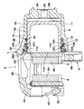
- FIG. 1 is a plan view of a disc brake according to an embodiment of the present invention.
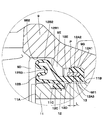
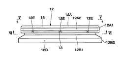
- FIG. 2 is a sectional view of the disc brake as seen from the direction of arrow II-II in FIG. 1. It is an expanded sectional view of the III section in FIG. 2 which shows a piston boot. It is a side view which shows a piston boot alone.
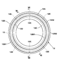
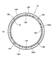
- FIG. 5 is a plan view of the piston boot as seen from the direction of arrows VV in FIG. 4.
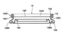
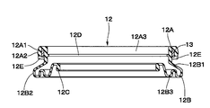
- FIG. 6 is a cross-sectional view of the piston boot as seen from the direction of arrows VI-VI in FIG. 4.
- FIG. 7 is a cross-sectional view of the piston boot as seen from the direction of arrows VII-VII in FIG. 5.
- FIG. 8 is a cross-sectional view of the piston boot seen from the direction of arrows VIII-VIII in FIG. 5.
- the disk 1 shown in FIG. 1 rotates in the direction of arrow A in FIG. 1 together with wheels (not shown) when the vehicle travels in the forward direction, and rotates in the direction of arrow B when the vehicle moves backward. To do.
- the disc brake 2 has a carrier 3 as a mounting member that is fixed to a non-rotating portion (not shown) on the vehicle body side.
- the carrier 3 is arranged in the rotational direction (circumferential direction) of the disc 1 so as to be axially astride the outer peripheral side of the disc 1, and has a pair of arm portions 3A, 3A extending in the axial direction of the disc 1, and A thick-walled support portion 3B, which is provided by integrally connecting the base end sides of the arm portions 3A and is fixed to the non-rotating portion of the vehicle on the inner side which is one side in the axial direction of the disc 1, It is configured to include.
- the carrier 3 is integrally formed with a reinforcing beam 3C that connects the tip ends of the arm portions 3A to each other on the outer side, which is the other side in the axial direction of the disc 1.
- the arms 3A of the carrier 3 are integrally connected by the support portion 3B on the inner side of the disc 1 and the reinforcing beam 3C on the outer side of the disc 1.
- Pad guides (not shown) having a U-shaped cross section for guiding a friction pad 8 described later in the axial direction of the disc 1 are formed on both sides of the arm portion 3A in the axial direction with the disc 1 sandwiched therebetween.
- the caliper 4 is slidably supported by the carrier 3.
- the caliper 4 extends from the inner leg 4A to the outer side of the disc 1 so as to straddle the outer peripheral side of the disc 1 between the inner leg 4A provided on the inner side of the disc 1 and each arm 3A of the carrier 3.
- the bridge portion 4B is provided, and the outer leg portion 4C extends inward in the radial direction of the disc 1 from the outer side, which is the tip side of the bridge portion 4B, and the tip side is a bifurcated claw portion 4C1.
- the inner leg 4A of the caliper 4 is provided with a cylinder 9 and a piston 11 described later.
- the inner leg portion 4A is provided with a pair of mounting portions 4D protruding in the rotation direction of the disc 1.
- the respective mounting portions 4D slidably support the caliper 4 as a whole with respect to the respective arm portions 3A of the carrier 3 via the sliding pins 5.
- the sliding pin 5 is fastened to each mounting portion 4D of the caliper 4 with a bolt 6.
- the tip end side of each sliding pin 5 is slidably inserted into a pin hole (not shown) formed in each arm 3A of the carrier 3 along the axial direction of the disk 1.
- Protective boots 7 are attached between each arm 3A and each sliding pin 5 to prevent rainwater or the like from entering between the sliding pin 5 and the pin hole of the arm 3A.
- the friction pads 8 are arranged in pairs so as to face both sides (inner side and outer side) of the disc 1.
- the inner-side and outer-side friction pads 8 have a lining 8A that receives a frictional force due to contact with the disc 1.
- brake fluid pressure is supplied into the bore 9A of the cylinder 9 described later, and the piston 11 moves toward the disc 1.
- the inner friction pad 8 is pressed against the disc 1 by the piston 11, and the caliper 4 is displaced toward the inner side by the reaction force from the piston 11.
- the claw portion 4C1 of the outer leg portion 4C presses the outer side friction pad 8 against the disc 1, and the inner side and outer side friction pads 8 are pressed against both sides of the disc 1 to control the disc 1. Power is given.
- the cylinder 9 is provided on the inner leg portion 4A of the caliper 4.
- the cylinder 9 has a bore portion 9A formed of a bottomed circular hole, and a piston 11 is slidably fitted in the bore portion 9A.
- One side in the axial direction of the cylinder 9 becomes a bottom portion 9B of the bore portion 9A, and a brake fluid passage 9C penetrating in the axial direction is formed in the center portion of the bottom portion 9B.
- Brake fluid pressure is supplied to and discharged from the bore portion 9A of the cylinder 9 through the brake fluid passage 9C.
- the other side in the axial direction of the cylinder 9 is an open end 9D, and the piston 11 is inserted into the bore portion 9A through this open end 9D.
- an annular step portion 9E having a diameter dimension larger than the inner diameter of the bore portion 9A is formed concentrically with the bore portion 9A.
- the step portion 9E is configured by a small diameter step portion 9E1 located on the bottom portion 9B side and a large diameter step portion 9E2 having a diameter dimension larger than that of the small diameter step portion 9E1 and being axially adjacent to the small diameter step portion 9E1.
- a large-diameter fitting portion 12A of the piston boot 12 described later is fitted in the small-diameter step portion 9E1, and a bellows portion 12B of the piston boot 12 described later is accommodated in the large-diameter step portion 9E2.
- An annular seal groove 9F is formed over the entire circumference at a position closer to the bottom 9B than the step 9E of the cylinder 9.
- An O-ring 10 is attached to the seal groove 9F, and the O-ring 10 seals between the inner peripheral surface of the bore portion 9A of the cylinder 9 and the outer peripheral surface 11B of the piston 11 described later.
- the piston 11 is accommodated in the bore 9A of the cylinder 9 so as to be movable in the axial direction.
- the piston 11 is formed in a bottomed cylindrical shape, and the tip 11A of the piston 11 projects from the bore portion 9A and is in contact with the friction pad 8.
- the piston 11 projects from the bore portion 9A and presses the friction pad 8 toward the disc 1.
- An annular groove 11C is formed over the entire circumference on the outer peripheral surface 11B of the piston 11 on the tip 11A side.
- a small-diameter fitting portion 12C of a piston boot 12 described later is fitted in the annular groove 11C.
- the piston boot 12 is provided between the tip 11A side of the piston 11 and the small diameter stepped portion 9E1 of the cylinder 9.
- the piston boot 12 expands and contracts with the movement of the piston 11, seals between the inner peripheral surface of the cylinder 9 (bore portion 9A) and the outer peripheral surface 11B of the piston 11, and foreign matter such as dust and rainwater enters. Has a role to prevent.
- the piston boot 12 is integrally molded using a flexible material such as rubber or synthetic resin, and has a large-diameter fitting portion 12A, a metal member 13, and a bellows portion 12B. And a small diameter fitting portion 12C and an annular protruding portion 12D.
- the large-diameter fitting portion 12A as a fitting portion is provided by being fitted to the small-diameter step portion 9E1 of the cylinder 9.
- the large-diameter fitting portion 12A is formed in an annular shape (cylindrical shape) corresponding to the small-diameter step portion 9E1 of the cylinder 9, and includes (embeds) an annular metal member 13.
- the metal member 13 is made of an annular body having a diameter larger than the inner diameter of the bore portion 9A of the cylinder 9 and smaller than the inner diameter of the small diameter step portion 9E1, and is integrally formed with the piston boot 12.
- the metal member 13 increases the rigidity of the large diameter fitting portion 12A.
- the outer peripheral surface 12A1 of the large-diameter fitting portion 12A is provided with an annular outer peripheral projection 12A2 over the entire circumference.
- the outer peripheral projection 12A2 is fitted into the annular recess 9G formed on the inner peripheral surface of the small diameter stepped portion 9E1 of the cylinder 9 so that the large diameter fitting portion 12A is removed from the small diameter stepped portion 9E1 of the cylinder 9. I have stopped.
- the bellows portion 12B extends from the large-diameter fitting portion 12A to the opening end 9D side of the cylinder 9, and is housed in the large-diameter step portion 9E2 of the cylinder 9.
- the bellows portion 12B extends from the large-diameter fitting portion 12A to the open end 9D side of the cylinder 9 and has an extending portion 12B1 that is expanded from the outer peripheral surface 12A1 of the large-diameter fitting portion 12A to the outer peripheral side (outer side in the radial direction).
- the elastic portion 12B3 is folded back from the outer peripheral end 12B2 of the extending portion 12B1 to the inner side in the radial direction, and extends and contracts in a bellows shape to the inner peripheral side of the inner peripheral surface 12A3 of the large diameter fitting portion 12A. It is configured.
- the outer peripheral end 12B2 of the extending portion 12B1 is arranged radially outside the outer peripheral surface 12A1 of the large diameter fitting portion 12A (see FIG. 3 ).
- the small-diameter fitting portion 12C is provided at the radially inner end of the expandable portion 12B3 that constitutes the bellows portion 12B.
- the small-diameter fitting portion 12C is formed in an annular shape having a smaller diameter than the large-diameter fitting portion 12A, and is fitted in the annular groove 11C of the piston 11.
- the annular protruding portion 12D is provided on the inner peripheral surface 12A3 of the large diameter fitting portion 12A.
- the annular projecting portion 12D projects annularly from the inner peripheral surface 12A3 of the large-diameter fitting portion 12A over the entire circumference and contacts the outer peripheral surface 11B of the piston 11, thereby centering the piston 11 with respect to the bore portion 9A of the cylinder 9. It secures sex.
- the annular protrusion 12D has a cross-sectional center of the metal member 13 in the axial direction of the piston 11. It is formed at a position closer to the bellows portion 12B by a dimension L than P.
- the bellows portion 12B of the piston boot 12 has greater flexibility and is more easily deformed than the large-diameter fitting portion 12A including the metal member 13. For this reason, when removing the molded piston boot 12 from the mold, the bellows part 12B that is easily deformed is sequentially removed from the mold to the large-diameter fitting part 12A that is difficult to be deformed. On the other hand, since the annular protruding portion 12D is arranged closer to the bellows portion 12B than the center P of the cross section of the metal member 13, it can be easily removed from the mold by deforming together with the bellows portion 12B. It is composed.
- the plurality of cutout portions 12E are provided at a portion where the large-diameter fitting portion 12A and the extending portion 12B1 of the bellows portion 12B intersect, that is, a portion on the bellows portion 12B side of the large-diameter fitting portion 12A.
- the plurality of cutouts 12E are arranged at a plurality of locations (for example, six locations) spaced apart from each other in the circumferential direction of the metal member 13. At the positions of these notches 12E, the metal member 13 is not covered with the rubber of the piston boot 12, and the metal member 13 is exposed to the outside. That is, the large-diameter fitting portion 12A of the piston boot 12 has a plurality of cutout portions 12E at the position on the bellows portion 12B side in which a part of the metal member 13 is exposed to the outside.
- the piston boot 12 including the annular metal member 13 is manufactured using a mold (not shown) including a lower mold, an upper mold, and a middle mold.
- a rubber material is injected into the mold while the metal member 13 is positioned (constrained) with respect to the lower mold by using a plurality of positioning tools (not shown).
- the piston boot 12 including the metal member 13 can be integrally formed. Therefore, a plurality of cutouts 12E are formed in a portion of the large diameter fitting portion 12A corresponding to the positioning tool, and in each of these cutouts 12E, a part of the metal member 13 is not covered with the rubber material. It is exposed to the outside.
- the outer peripheral end 12B2 of the extending portion 12B1 forming the bellows portion 12B is expanded to the outer peripheral side (radially outer side) of the outer peripheral surface 12A1 of the large diameter fitting portion 12A. Therefore, each notch 12E provided in the portion of the large-diameter fitting portion 12A on the side of the bellows portion 12B is covered with the bellows portion 12B in the axial direction of the piston 11. As a result, even if the muddy water is scattered toward the piston 11 when the vehicle is traveling, the muddy water is blocked by the bellows portion 12B of the piston boot 12 and does not reach the large-diameter fitting portion 12A. Therefore, it is possible to prevent the muddy water from entering the notches 12E formed in the large-diameter fitting portion 12A and protect the metal member 13 from the muddy water, thereby increasing the corrosion resistance of the metal member 13. There is.
- the bellows portion 12B arranged between the large diameter fitting portion 12A and the small diameter fitting portion 12C of the piston boot 12 is an extension portion extending from the large diameter fitting portion 12A to the opening end 9D side of the cylinder 9. 12B1 and an expanding/contracting portion 12B3 that is folded back inward in the radial direction from the outer peripheral end 12B2 of the extending portion 12B1 and extends to the small diameter fitting portion 12C. That is, the bellows portion 12B is bent in the radial direction at a position displaced from the large diameter fitting portion 12A and the small diameter fitting portion 12C in the axial direction of the piston 11 toward the opening end 9D side of the cylinder 9.
- the diameter of the piston boot 12 is The dimension in the direction can be kept small.
- the layout of the cylinder 9 on which the piston boot 12 is provided on the side of the open end 9D can be narrowed, and the caliper 4 can be reduced in weight.
- a mold including a lower mold, an upper mold, and a middle mold is usually used. Then, the annular metal member is positioned (constrained) with respect to the lower mold and the like by using a positioning jig, and a rubber material is injected into the mold (cavity), whereby the piston boot including the metal member is included.
- a positioning jig is used to position the metal member, the portion of the metal member that is in contact with the positioning jig is exposed to the outside without being covered with the rubber material.
- the molded piston boot Since a plurality of positioning jigs are usually arranged in the circumferential direction of the metal member, the molded piston boot is formed with a plurality of notches in which a part of the metal member is exposed to the outside. For this reason, when muddy water is scattered toward the piston when the vehicle is running, there is a problem that the muddy water penetrates into each notch of the piston boot and the corrosion resistance of the metal member deteriorates.
- each of the cutout portions 12E has a large diameter fitting. It is arranged at a portion of the joint portion 12A on the side of the bellows portion 12B. Thereby, each notch 12E can be covered by the bellows 12B whose diameter is expanded from the large-diameter fitting portion 12A to the outer peripheral side (radially outside). Therefore, muddy water scattered on the piston 11 when the vehicle is traveling can be blocked by the bellows portion 12B, and muddy water can be prevented from adhering to the metal member 13 through each notch 12E.
- the disc brake 2 according to the present embodiment has the above-mentioned configuration. Next, the operation of the disc brake 2 will be described.
- the piston boot 12 expands and contracts (elastically deforms) as the piston 11 moves, and seals between the inner peripheral surface of the cylinder 9 (bore portion 9A) and the outer peripheral surface 11B of the piston 11 to prevent dust and dirt. Prevent foreign objects such as rainwater from entering.
- the metal member 13 is positioned with respect to the mold by using a positioning jig (neither is shown). By doing so, a plurality of notches 12E are formed in the large-diameter fitting portion 12A. Therefore, a part of the metal member 13 integrally formed with the piston boot 12 is exposed to the outside at the position of each notch 12E.
- each notch portion 12E is provided at a position on the bellows portion 12B side of the large-diameter fitting portion 12A, and the outer peripheral end 12B2 of the extending portion 12B1 forming the bellows portion 12B is the outer circumference of the large-diameter fitting portion 12A.
- the diameter is expanded from the surface 12A1 to the outer peripheral side. Therefore, each notch 12E is covered with the bellows 12B in the axial direction of the piston 11.
- the muddy water is scattered toward the piston 11 when the vehicle is traveling, the muddy water is blocked by the bellows portion 12B of the piston boot 12 and does not reach the large-diameter fitting portion 12A.
- it is possible to improve the corrosion resistance of the metal member 13 by suppressing the intrusion of muddy water into each notch 12E formed in the large-diameter fitting portion 12A and protecting the metal member 13 from muddy water.
- each notch 12E is adopted. It is possible to suppress the infiltration of muddy water. As a result, it is possible to expand the choices of the structure of the mold for molding the piston boot 12 and to simplify the mold structure, which can also contribute to the reduction of the manufacturing cost of the piston boot 12.
- the annular protrusion 12D provided on the inner peripheral surface 12A3 of the large-diameter fitting portion 12A of the piston boot 12 is located closer to the bellows portion 12B than the cross-sectional center P of the metal member 13 included in the large-diameter fitting portion 12A. It is located in a close position.
- the annular protrusion 12D by disposing the annular protrusion 12D near the bellows portion 12B which is more easily deformed than the large-diameter fitting portion 12A including the metal member 13, it is possible to remove the molded piston boot 12 from the mold.
- the annular protrusion 12D together with the bellows 12B can be easily removed from the mold.
- the disc brake 2 has a piston 11 and a bore portion 9A that movably accommodates the piston 11, and a cylinder having an annular step portion 9E formed on the open end 9D side of the bore portion 9A.
- a piston boot 12 disposed between the tip side of the piston 11 and the small diameter step 9E1 of the cylinder 9.
- the piston boot 12 includes an annular metal member 13 and is fitted into the small diameter step 9E1.
- An annular large-diameter fitting portion 12A that fits together with the large-diameter fitting portion 12A, extends from the large-diameter fitting portion 12A to the outer peripheral side, and bends to the inner peripheral side of the large-diameter fitting portion 12A.
- the piston boot 12 includes a bellows portion 12B extending in a vertical direction, and a small diameter fitting portion 12C formed in an end portion of the bellows portion 12B in an annular shape having a diameter smaller than that of the large diameter fitting portion 12A and fitting to the outer circumference of the piston 11.
- the large-diameter fitting portion 12A has a cutout portion 12E in which a part of the metal member 13 is exposed to the outside at a position on the side of the bellows portion 12B.
- the notch 12E provided in the large-diameter fitting portion 12A can be covered with the bellows portion 12B whose diameter is expanded from the large-diameter fitting portion 12A to the outer peripheral side in the axial direction of the piston 11.
- the muddy water scattered toward the piston 11 when the vehicle is running is blocked by the bellows portion 12B of the piston boot 12, so that the muddy water can be prevented from entering the cutout portion 12E, and the corrosion resistance of the metal member 13 can be reduced. Can be increased.
- the bellows portion 12B is formed by extending the large diameter fitting portion 12A toward the opening end 9D of the cylinder 9 and the small diameter fitting portion that is folded back inward in the radial direction from the outer peripheral end 12B2 of the extending portion 12B1. It is composed of a stretchable portion 12B3 extending to 12C. That is, the bellows portion 12B is bent in the radial direction at a position displaced from the large diameter fitting portion 12A and the small diameter fitting portion 12C in the axial direction of the piston 11 toward the opening end 9D side of the cylinder 9.
- the radial dimension of the piston boot 12 can be suppressed to be small, the layout on the side of the open end 9D of the cylinder 9 in which the piston boot 12 is provided can be narrowed, and the weight of the caliper 4 can be reduced.
- the disc brake 2 including the pair of bore portions 9A and the piston 11 is described as an example.
- the present invention is not limited to this, for example, it is configured to include two sets of bore portions and pistons, and the opposed pistons are arranged in the axial direction with the disk interposed therebetween, and the opposed disk brakes press the pads from both sides. Can also be applied to.
- a bore portion that accommodates a piston so as to be movable in the axial direction is provided, and a diameter dimension that is larger than an inner diameter of the bore portion is provided on an open end side of the bore portion from which a tip of the piston projects.
- a cylinder formed with an annular step portion, the piston for pressing at least one of a pair of pads facing each other on both sides of the disk, and arranged between the tip side of the piston and the step portion of the cylinder.
- a piston boot having a bellows portion that can expand and contract with the movement of the piston, wherein the piston boot includes an annular large-diameter fitting portion that includes an annular metal member and is fitted into the step portion.
- the bellows portion extending from the large-diameter fitting portion to the outer peripheral side of the large-diameter fitting portion and flexibly extending to the inner peripheral side of the large-diameter fitting portion, and the bellows portion.
- the end portion has a small-diameter fitting portion that is formed in an annular shape having a smaller diameter than the large-diameter fitting portion and fits on the outer circumference of the piston, and the large-diameter fitting portion of the piston boot has the bellows side.
- a part of the metal member has a notch exposed to the outside at the position.
- the large-diameter fitting portion of the piston boot has an annular protruding portion that is formed on an inner peripheral side and abuts an outer peripheral surface of the piston. Is formed at a position closer to the bellows portion than the center of the cross section of the metal member in the axial direction of the piston.
- a third aspect is characterized in that, in the first or second aspect, the cutout portions are formed at a plurality of positions in the circumferential direction of the large diameter fitting portion.
- a step portion formed on an opening side of a cylinder having a bore portion provided in a caliper of a disc brake and a tip end side of a piston housed in the bore portion so as to be axially movable.
- a piston boot having a bellows portion that is disposed between and has a bellows portion that can expand and contract with the movement of the piston, wherein the piston boot includes a ring-shaped metal member and is fitted into the stepped portion.
- the end portion of the bellows portion is formed in an annular shape having a smaller diameter than the large-diameter fitting portion, and has a small-diameter fitting portion that fits on the outer circumference of the piston, and the large-diameter fitting portion of the piston boot,
- a part of the metal member has a notch exposed to the outside at a position on the side of the bellows.
- the large-diameter fitting portion of the piston boot has an annular protruding portion that is formed on an inner peripheral side and abuts an outer peripheral surface of the piston, and the annular protruding portion. Is formed at a position closer to the bellows portion than the center of the cross section of the metal member in the axial direction of the piston.
- a sixth aspect is characterized in that, in the fourth or fifth aspect, the cutout portions are formed at a plurality of positions in the circumferential direction of the large diameter fitting portion.
- the present invention is not limited to the above-described embodiment, and various modifications are included.
- the above-described embodiments have been described in detail in order to explain the present invention in an easy-to-understand manner, and are not necessarily limited to those having all the configurations described.
- a part of the configuration of one embodiment can be replaced with the configuration of another embodiment, and the configuration of another embodiment can be added to the configuration of one embodiment.
Landscapes
- Engineering & Computer Science (AREA)
- General Engineering & Computer Science (AREA)
- Mechanical Engineering (AREA)
- Braking Arrangements (AREA)
- Sealing Devices (AREA)
- Diaphragms And Bellows (AREA)
Abstract
ディスクブレーキは、ピストンと、ピストンを移動可能に収容するボア部を有し、ボア部の開口端側に段部が形成されたシリンダと、ピストンの先端側とシリンダの小径段部との間に配置されたピストンブーツとを備え、ピストンブーツは、環状の金属部材を内包して小径段部に嵌合する大径嵌合部と、大径嵌合部から延出して大径嵌合部より外周側まで拡径すると共に大径嵌合部よりも内周側へと撓んで延びる蛇腹部と、蛇腹部の端部に形成されピストンの外周に嵌合する小径嵌合部とを有する。ピストンブーツの大径嵌合部は、蛇腹部側の位置に金属部材の一部が外部に露出した切欠部を有している。
Description
本発明は、例えば、自動車等の車両に制動力を付与するディスクブレーキ及びディスクブレーキに用いられるピストンブーツに関する。
一般に、自動車等の車両に設けられるディスクブレーキは、シリンダのボア部内に摺動可能に挿嵌されたピストンが摩擦パッドを押圧することにより、車両に制動力を付与する。シリンダの開口側には環状の段部が形成され、この段部とピストンとの間には可撓性を有するピストンブーツが設けられている。
ここで、ピストンブーツは、シリンダの段部に嵌合する環状の嵌合部を有し、この嵌合部に環状の金属部材を内包することにより、シリンダに対する組付性やピストンブーツの耐久性を向上させることができる(特許文献1参照)。
しかし、環状の金属部材を内包したピストンブーツにおいては、製造上の理由により、嵌合部の周囲に金属部材の一部が外部に露出する切欠部が形成される。このため、泥水等が切欠部を通じて金属部材に付着することにより、金属部材の耐食性が低下してしまうという問題がある。
本発明の目的は、ピストンブーツに内包された金属部材の耐食性を高めることができるディスクブレーキ及びディスクブレーキに用いられるピストンブーツを提供することにある。
本発明の一実施形態に係るディスクブレーキは、ディスクの両面にそれぞれ対向する一対のパッドのうち少なくとも一つを押圧するピストンと、前記ピストンを軸方向に移動可能に収容する有底なボア部を有し、前記ピストンの先端が突出する前記ボア部の開口端側に前記ボア部の内径よりも大きな径寸法を有する環状の段部が形成されたシリンダと、前記ピストンの先端側と前記シリンダの前記段部との間に配置され、前記ピストンの移動に伴って伸縮可能な蛇腹部を有するピストンブーツとを備え、前記ピストンブーツは、環状の金属部材を内包して前記段部に嵌合する環状の大径嵌合部と、前記大径嵌合部から延出して前記大径嵌合部より外周側まで拡径すると共に前記大径嵌合部よりも内周側へと撓んで延びる前記蛇腹部と、前記蛇腹部の端部に前記大径嵌合部よりも小径な環状に形成され前記ピストンの外周に嵌合する小径嵌合部とを有し、前記ピストンブーツの前記大径嵌合部は、前記蛇腹部側の位置に前記金属部材の一部が外部に露出した切欠部を有することを特徴としている。
また、本発明の一実施形態に係るピストンブーツは、ディスクブレーキのキャリパに設けられたボア部を有するシリンダの開口端側に形成された段部と、前記ボア部に軸方向に移動可能に収容されたピストンの先端側との間に配置され、前記ピストンの移動に伴って伸縮可能な蛇腹部を有するピストンブーツであって、前記ピストンブーツは、環状の金属部材を内包して前記段部に嵌合する環状の大径嵌合部と、前記大径嵌合部から延出して前記大径嵌合部より外周側まで拡径すると共に前記大径嵌合部よりも内周側へと撓んで延びる前記蛇腹部と、前記蛇腹部の端部に前記大径嵌合部よりも小径な環状に形成され、前記ピストンの外周に嵌合する小径嵌合部とを有し、前記ピストンブーツの前記大径嵌合部は、前記蛇腹部側の位置に前記金属部材の一部が外部に露出した切欠部を有することを特徴としている。
本発明の一実施形態によれば、泥水等が大径嵌合部の切欠部を通じて金属部材に付着するのを抑え、金属部材の耐食性を高めることができる。
以下、本発明を実施するための形態を添付図面に従って詳細に説明する。
図1中に示すディスク1は、例えば、車両が前進方向に走行するときに車輪(図示せず)と共に図1中の矢示A方向に回転し、車両が後退するときには矢示B方向に回転するものである。
本実施の形態に係るディスクブレーキ2は、車体側の非回転部分(図示せず)に固定される取付部材としてのキャリア3を有している。このキャリア3は、ディスク1の回転方向(周方向)に離間してディスク1の外周側を軸方向に跨いで配置され、ディスク1の軸方向に延びた一対の腕部3A,3Aと、各腕部3Aの基端側を一体化するように連結して設けられ、ディスク1の軸方向の一側であるインナ側で前記車両の非回転部分に固定される厚肉の支承部3Bとを含んで構成されている。
また、キャリア3には、ディスク1の軸方向の他側であるアウタ側で各腕部3Aの先端側を互いに連結する補強ビーム3Cが一体に形成されている。これにより、キャリア3の各腕部3Aは、ディスク1のインナ側で支承部3Bにより一体的に連結されると共に、ディスク1のアウタ側で補強ビーム3Cにより一体的に連結されている。各腕部3Aには、ディスク1を挟む軸方向両側に、後述する摩擦パッド8をディスク1の軸方向にガイドする断面コ字状のパッドガイド(図示せず)が形成されている。
キャリパ4は、キャリア3に摺動可能に支持されている。キャリパ4は、ディスク1のインナ側に設けられたインナ脚部4Aと、キャリア3の各腕部3A間でディスク1の外周側を跨ぐようにインナ脚部4Aからディスク1のアウタ側へと延設されたブリッジ部4Bと、ブリッジ部4Bの先端側であるアウタ側からディスク1の径方向内向きに延び、先端側が二又状の爪部4C1となったアウタ脚部4Cとにより構成されている。そして、キャリパ4のインナ脚部4Aには、後述するシリンダ9およびピストン11が設けられている。
また、インナ脚部4Aには、ディスク1の回転方向に突出する一対の取付部4Dが設けられている。これら各取付部4Dは、摺動ピン5を介して、キャリパ4全体をキャリア3の各腕部3Aに対して摺動可能に支持している。摺動ピン5は、キャリパ4の各取付部4Dにそれぞれボルト6を用いて締結されている。各摺動ピン5の先端側は、キャリア3の各腕部3Aにディスク1の軸方向に沿って形成されたピン穴(図示せず)内に摺動可能に挿嵌されている。各腕部3Aと各摺動ピン5との間には、それぞれ保護ブーツ7が取付けられ、摺動ピン5と腕部3Aのピン穴との間に雨水等が浸入するのを防いでいる。
摩擦パッド8は、ディスク1の両面(インナ側とアウタ側)に対向した状態で対をなして配置されている。これらインナ側とアウタ側の摩擦パッド8は、ディスク1との接触により摩擦力を受けるライニング8Aを有している。ディスクブレーキ2の作動時には、後述するシリンダ9のボア部9A内にブレーキ液圧が供給され、ピストン11がディスク1に向けて移動する。これにより、インナ側の摩擦パッド8がピストン11によりディスク1に押圧され、キャリパ4は、ピストン11からの反力によってインナ側に変位する。この結果、アウタ脚部4Cの爪部4C1が、アウタ側の摩擦パッド8をディスク1に押圧し、ディスク1の両面にインナ側とアウタ側の摩擦パッド8が押付けられることにより、ディスク1に制動力が付与される。
シリンダ9は、キャリパ4のインナ脚部4Aに設けられている。シリンダ9は、有底な円形穴からなるボア部9Aを有し、ボア部9A内にはピストン11が摺動可能に挿嵌されている。シリンダ9の軸方向の一側はボア部9Aの底部9Bとなり、底部9Bの中心部には軸方向に貫通するブレーキ液通路9Cが形成されている。このブレーキ液通路9Cを通じて、シリンダ9のボア部9Aに対するブレーキ液圧の給排が行われる。シリンダ9の軸方向の他側は開口端9Dとなり、この開口端9Dを通じてピストン11がボア部9A内に挿入されている。
シリンダ9の開口端9D側には、ボア部9Aの内径よりも大きな径寸法を有する環状の段部9Eが、ボア部9Aと同心上に形成されている。段部9Eは、底部9B側に位置する小径段部9E1と、小径段部9E1の径寸法よりも大きな径寸法を有し小径段部9E1に軸方向で隣接する大径段部9E2とにより構成されている。小径段部9E1には、後述するピストンブーツ12の大径嵌合部12Aが嵌合し、大径段部9E2には、後述するピストンブーツ12の蛇腹部12Bが収容されている。シリンダ9の段部9Eよりも底部9B側となる位置には、全周に亘って環状のシール溝9Fが形成されている。シール溝9FにはOリング10が取付けられ、このOリング10によって、シリンダ9のボア部9Aの内周面と後述するピストン11の外周面11Bとの間がシールされている。
ピストン11は、シリンダ9のボア部9A内に軸方向に移動可能に収容されている。ピストン11は有底な円筒状に形成され、ピストン11の先端11Aはボア部9Aから突出し、摩擦パッド8に当接している。ピストン11は、シリンダ9のブレーキ液通路9Cを通じてボア部9A内にブレーキ液圧が供給されることにより、ボア部9Aから突出して摩擦パッド8をディスク1に向けて押圧する。ピストン11の先端11A側の外周面11Bには、全周に亘って環状溝11Cが形成されている。この環状溝11Cには、後述するピストンブーツ12の小径嵌合部12Cが嵌合している。
次に、本実施の形態に用いられるピストンブーツについて説明する。
図2および図3に示すように、ピストンブーツ12は、ピストン11の先端11A側とシリンダ9の小径段部9E1との間に設けられている。ピストンブーツ12は、ピストン11の移動に伴って伸縮し、シリンダ9(ボア部9A)の内周面とピストン11の外周面11Bとの間をシールし、ダストや雨水等の異物が侵入するのを防止する役割を担っている。図4ないし図8に示すように、ピストンブーツ12は、ゴム又は合成樹脂等の可撓性を有する材料を用いて一体成形され、大径嵌合部12Aと、金属部材13と、蛇腹部12Bと、小径嵌合部12Cと、環状突出部12Dとを含んで構成されている。
嵌合部としての大径嵌合部12Aは、シリンダ9の小径段部9E1に嵌合して設けられている。大径嵌合部12Aは、シリンダ9の小径段部9E1に対応する環状(円筒状)に形成され、環状の金属部材13を内包(埋設)している。ここで、金属部材13は、シリンダ9のボア部9Aの内径よりも大径で小径段部9E1の内径よりも小径な環状体からなり、ピストンブーツ12と一体成形されている。金属部材13は、大径嵌合部12Aの剛性を増大させている。大径嵌合部12Aの外周面12A1には、全周に亘って環状の外周突起12A2が設けられている。外周突起12A2は、シリンダ9の小径段部9E1の内周面に形成された環状の凹陥部9Gに嵌合することにより、大径嵌合部12Aをシリンダ9の小径段部9E1に対して抜止めしている。
蛇腹部12Bは、大径嵌合部12Aからシリンダ9の開口端9D側に延出し、シリンダ9の大径段部9E2内に収容されている。蛇腹部12Bは、大径嵌合部12Aからシリンダ9の開口端9D側に延び、大径嵌合部12Aの外周面12A1より外周側(径方向の外側)まで拡径した延出部12B1と、延出部12B1の外周端12B2から径方向の内側へと折返され、大径嵌合部12Aの内周面12A3よりも内周側へと蛇腹状に撓んで延びる伸縮部12B3とを含んで構成されている。この場合、延出部12B1の外周端12B2は、大径嵌合部12Aの外周面12A1よりも径方向外側に配置されている(図3参照)。小径嵌合部12Cは、蛇腹部12Bを構成する伸縮部12B3の径方向の内側の端部に設けられている。小径嵌合部12Cは、大径嵌合部12Aよりも小径な環状に形成され、ピストン11の環状溝11Cに嵌合している。
環状突出部12Dは、大径嵌合部12Aの内周面12A3に設けられている。環状突出部12Dは、大径嵌合部12Aの内周面12A3から全周に亘って環状に突出し、ピストン11の外周面11Bに当接することにより、シリンダ9のボア部9Aに対するピストン11のセンタリング性を確保している。ここで、図3に示すように、大径嵌合部12Aに内包された金属部材13の断面の中心をPとすると、環状突出部12Dは、ピストン11の軸方向において金属部材13の断面中心Pよりも寸法Lだけ蛇腹部12Bに近い位置に形成されている。
ピストンブーツ12の蛇腹部12Bは、金属部材13を内包する大径嵌合部12Aよりも可撓性が大きく変形し易い。このため、成形されたピストンブーツ12を金型から取外す場合には、変形し易い蛇腹部12Bから変形し難い大径嵌合部12Aへと順に金型から取外していく。これに対し、環状突出部12Dは、金属部材13の断面中心Pよりも蛇腹部12B側に配置されているため、蛇腹部12Bと一緒に変形させることにより、金型から容易に取外すことができる構成となっている。
複数の切欠部12Eは、大径嵌合部12Aと蛇腹部12Bの延出部12B1とが交わる部位、即ち、大径嵌合部12Aのうち蛇腹部12B側となる部位に設けられている。これら複数の切欠部12Eは、金属部材13の周方向に離間して複数箇所(例えば6箇所)に配置されている。これら切欠部12Eの位置では、金属部材13がピストンブーツ12のゴムによって被覆されておらず、金属部材13は外部に露出している。即ち、ピストンブーツ12の大径嵌合部12Aは、蛇腹部12B側の位置に、金属部材13の一部が外部に露出した複数の切欠部12Eを有している。
ここで、環状の金属部材13を内包したピストンブーツ12は、下型、上型、中型等からなる金型(いずれも図示せず)を用いて製造される。このピストンブーツ12を製造する場合には、前記下型に対し複数の位置決め具(図示せず)を用いて金属部材13を位置決め(拘束)した状態で、金型内にゴム材料を注入する。これにより、金属部材13を内包したピストンブーツ12を一体成形することができる。従って、大径嵌合部12Aのうち位置決め具に対応する部位には、複数個の切欠部12Eが形成され、これら各切欠部12Eでは、金属部材13の一部がゴム材料によって被覆されない状態で外部に露出している。
この場合、蛇腹部12Bを構成する延出部12B1の外周端12B2は、大径嵌合部12Aの外周面12A1よりも外周側(径方向外側)まで拡径している。このため、大径嵌合部12Aのうち蛇腹部12B側の部位に設けられた各切欠部12Eは、ピストン11の軸方向において蛇腹部12Bによって覆われている。これにより、車両の走行時に泥水がピストン11に向けて飛散したとしても、この泥水はピストンブーツ12の蛇腹部12Bに遮られることにより、大径嵌合部12Aまで達することがない。従って、大径嵌合部12Aに形成された各切欠部12Eに泥水が浸入するのを抑え、金属部材13を泥水から保護することにより、金属部材13の耐食性を高めることができる構成となっている。
また、ピストンブーツ12の大径嵌合部12Aと小径嵌合部12Cとの間に配置される蛇腹部12Bは、大径嵌合部12Aからシリンダ9の開口端9D側に延びた延出部12B1と、延出部12B1の外周端12B2から径方向の内側に折返され小径嵌合部12Cへと延びる伸縮部12B3とにより構成されている。即ち、蛇腹部12Bは、ピストン11の軸方向において大径嵌合部12Aおよび小径嵌合部12Cよりもシリンダ9の開口端9D側にずれた位置で径方向に撓んでいる。これにより、例えば特許文献1によるピストンブーツのように、蛇腹部が大径嵌合部と小径嵌合部との間で径方向に撓んで配置される構造に比較して、ピストンブーツ12の径方向の寸法を小さく抑えることができる。この結果、ピストンブーツ12が設けられるシリンダ9の開口端9D側のレイアウトを狭小化することができ、キャリパ4の軽量化を図ることができる構成となっている。
ここで、環状の金属部材を内包したピストンブーツを製造する場合には、通常、下型、上型、中型等からなる金型(成形型)が用いられる。そして、環状の金属部材を、位置決め治具を用いて下型等に対して位置決め(拘束)した状態で、金型(キャビティ)内にゴム材料を注入することにより、金属部材を内包したピストンブーツが一体成形される。しかし、位置決め治具を用いて金属部材を位置決めした場合には、金属部材のうち位置決め治具に接している部位は、ゴム材料によって被覆されない状態で外部に露出する。位置決め治具は、通常、金属部材の周方向に複数個配置されるので、成形されたピストンブーツには、金属部材の一部が外部に露出した複数の切欠部が形成される。このため、車両の走行時にピストンに向けて泥水が飛散すると、ピストンブーツの各切欠部に泥水が浸入し、金属部材の耐食性が低下してしまうという問題がある。
これに対し、本実施の形態によるピストンブーツ12は、製造上の理由により大径嵌合部12Aの周囲に複数の切欠部12Eが形成されたとしても、これら各切欠部12Eは、大径嵌合部12Aのうち蛇腹部12B側の部位に配置される。これにより、大径嵌合部12Aより外周側(径方向外側)まで拡径した蛇腹部12Bによって各切欠部12Eを覆うことができる。従って、車両の走行時にピストン11に飛散した泥水を、蛇腹部12Bによって遮ることができ、各切欠部12Eを通じて金属部材13に泥水が付着するのを防止することができる。
本実施の形態によるディスクブレーキ2は、上述の如き構成を有するもので、次に、ディスクブレーキ2の動作について説明する。
車両の走行時にブレーキ操作が行われると、キャリパ4に形成されたシリンダ9のボア部9A内に、ブレーキ液通路9Cを通じてブレーキ液圧が供給される。これにより、ピストン11がシリンダ9のボア部9A内を開口端9D側へと移動し、インナ側の摩擦パッド8を押圧する。このため、キャリパ4は、ピストン11からの反力によってインナ側に変位する。この結果、アウタ脚部4Cの爪部4C1が、アウタ側の摩擦パッド8をディスク1に押圧し、ディスク1の両面にインナ側とアウタ側の摩擦パッド8が押付けられることにより、車両に制動力が付与される。このとき、ピストンブーツ12は、ピストン11の移動に伴って伸縮(弾性変形)しつつ、シリンダ9(ボア部9A)の内周面とピストン11の外周面11Bとの間をシールし、ゴミや雨水等の異物が侵入するのを防止する。
この場合、ピストンブーツ12は、大径嵌合部12Aに環状の金属部材13を一体形成するときに、金型に対して位置決め治具(いずれも図示せず)を用いて金属部材13を位置決めすることにより、大径嵌合部12Aに複数の切欠部12Eが形成される。このため、ピストンブーツ12に一体成形された金属部材13の一部は、各切欠部12Eの位置で外部に露出している。
しかし、各切欠部12Eは、大径嵌合部12Aのうち蛇腹部12B側の位置に設けられ、蛇腹部12Bを構成する延出部12B1の外周端12B2は、大径嵌合部12Aの外周面12A1より外周側まで拡径している。従って、各切欠部12Eは、ピストン11の軸方向において蛇腹部12Bによって覆われている。これにより、車両の走行時に泥水がピストン11に向けて飛散したとしても、この泥水はピストンブーツ12の蛇腹部12Bに遮られることにより、大径嵌合部12Aまで達することがない。この結果、大径嵌合部12Aに形成された各切欠部12Eに泥水が浸入するのを抑え、金属部材13を泥水から保護することにより、金属部材13の耐食性を高めることができる。
換言すれば、ピストンブーツ12を成形する金型の構造として、大径嵌合部12Aのうち蛇腹部12B側の位置に各切欠部12Eが配置される構造を採用した場合でも、各切欠部12Eに泥水が浸入するのを抑制することができる。この結果、ピストンブーツ12を成形するための金型の構造の選択肢を広げたり、型構造の簡易化を図ることができ、ピストンブーツ12の製造コストの低減にも寄与することができる。
また、ピストンブーツ12の大径嵌合部12Aの内周面12A3に設けられた環状突出部12Dは、大径嵌合部12Aに内包された金属部材13の断面中心Pよりも蛇腹部12Bに近い位置に配置されている。このように、金属部材13を内包した大径嵌合部12Aよりも変形し易い蛇腹部12Bの近くに環状突出部12Dを配置することにより、成形されたピストンブーツ12を金型から取外す場合に、蛇腹部12Bと一緒に環状突出部12Dを容易に金型から取外すことができる。
かくして、本実施の形態によるディスクブレーキ2は、ピストン11と、ピストン11を移動可能に収容するボア部9Aを有し、ボア部9Aの開口端9D側に環状の段部9Eが形成されたシリンダ9と、ピストン11の先端側とシリンダ9の小径段部9E1との間に配置されたピストンブーツ12とを備え、ピストンブーツ12は、環状の金属部材13を内包して小径段部9E1に嵌合する環状の大径嵌合部12Aと、大径嵌合部12Aから延出して大径嵌合部12Aより外周側まで拡径すると共に大径嵌合部12Aよりも内周側へと撓んで延びる蛇腹部12Bと、蛇腹部12Bの端部に大径嵌合部12Aよりも小径な環状に形成され、ピストン11の外周に嵌合する小径嵌合部12Cとを有し、ピストンブーツ12の大径嵌合部12Aは、蛇腹部12B側の位置に金属部材13の一部が外部に露出した切欠部12Eを有している。
これにより、大径嵌合部12Aに設けられた切欠部12Eを、ピストン11の軸方向において、大径嵌合部12Aより外周側まで拡径した蛇腹部12Bによって覆うことができる。この結果、車両の走行時にピストン11に向けて飛散した泥水を、ピストンブーツ12の蛇腹部12Bによって遮ることにより、この泥水が切欠部12Eに浸入するのを抑えることができ、金属部材13の耐食性を高めることができる。
しかも、蛇腹部12Bは、大径嵌合部12Aからシリンダ9の開口端9D側に延びた延出部12B1と、延出部12B1の外周端12B2から径方向の内側に折返され小径嵌合部12Cへと延びる伸縮部12B3とにより構成されている。即ち、蛇腹部12Bは、ピストン11の軸方向において大径嵌合部12Aおよび小径嵌合部12Cよりもシリンダ9の開口端9D側にずれた位置で径方向に撓んでいる。この結果、ピストンブーツ12の径方向の寸法を小さく抑え、ピストンブーツ12が設けられるシリンダ9の開口端9D側のレイアウトを狭小化することができ、キャリパ4の軽量化を図ることができる。
なお、上述した各実施の形態では、1組のボア部9Aとピストン11を有するディスクブレーキ2を例に挙げて説明している。しかし、本発明はこれに限らず、例えば2組のボア部とピストンとを含んで構成し、対向した前記ピストンがディスクを挟んで軸方向に配置され、両側からパッドを押付ける対向型ディスクブレーキにも適用することができる。
以上説明した実施の形態に基づくディスクブレーキ及びピストンブーツとして、例えば以下に述べる態様のものが考えられる。
第1の態様としては、ピストンを軸方向に移動可能に収容するボア部を有し、前記ピストンの先端が突出する前記ボア部の開口端側に前記ボア部の内径よりも大きな径寸法を有する環状の段部が形成されたシリンダと、ディスクの両面にそれぞれ対向する一対のパッドのうち少なくとも一つを押圧する前記ピストンと、前記ピストンの先端側と前記シリンダの前記段部との間に配置され、前記ピストンの移動に伴って伸縮可能な蛇腹部を有するピストンブーツとを備え、前記ピストンブーツは、環状の金属部材を内包して前記段部に嵌合する環状の大径嵌合部と、前記大径嵌合部から延出して前記大径嵌合部より外周側まで拡径すると共に前記大径嵌合部よりも内周側へと撓んで延びる前記蛇腹部と、前記蛇腹部の端部に前記大径嵌合部よりも小径な環状に形成され前記ピストンの外周に嵌合する小径嵌合部とを有し、前記ピストンブーツの前記大径嵌合部は、前記蛇腹部側の位置に前記金属部材の一部が外部に露出した切欠部を有することを特徴としている。
第2の態様としては、第1の態様において、前記ピストンブーツの前記大径嵌合部は、内周側に形成され前記ピストンの外周面に当接する環状突出部を有し、前記環状突出部は、前記ピストンの軸方向において前記金属部材の断面中心よりも前記蛇腹部に近い位置に形成されていることを特徴としている。
第3の態様としては、第1または第2の態様において、前記切欠部は、前記大径嵌合部の周方向の複数個所に形成されていることを特徴としている。
第4の態様としては、ディスクブレーキのキャリパに設けられたボア部を有するシリンダの開口側に形成された段部と、前記ボア部に軸方向に移動可能に収容されたピストンの先端側との間に配置され、前記ピストンの移動に伴って伸縮可能な蛇腹部を有するピストンブーツであって、前記ピストンブーツは、環状の金属部材を内包して前記段部に嵌合する環状の大径嵌合部と、前記大径嵌合部から延出して前記大径嵌合部より外周側まで拡径すると共に前記大径嵌合部よりも内周側へと撓んで延びる前記蛇腹部と、前記蛇腹部の端部に前記大径嵌合部よりも小径な環状に形成され、前記ピストンの外周に嵌合する小径嵌合部とを有し、前記ピストンブーツの前記大径嵌合部は、前記蛇腹部側の位置に前記金属部材の一部が外部に露出した切欠部を有することを特徴としている。
第5の態様としては、第4の態様において、前記ピストンブーツの前記大径嵌合部は、内周側に形成され前記ピストンの外周面に当接する環状突出部を有し、前記環状突出部は、前記ピストンの軸方向において前記金属部材の断面中心よりも前記蛇腹部に近い位置に形成されていることを特徴としている。
第6の態様としては、第4または第5の態様において、前記切欠部は、前記大径嵌合部の周方向の複数個所に形成されていることを特徴としている。
尚、本発明は上記した実施形態に限定されるものではなく、様々な変形例が含まれる。例えば、上記した実施形態は本発明を分かりやすく説明するために詳細に説明したものであり、必ずしも説明した全ての構成を備えるものに限定されるものではない。また、ある実施形態の構成の一部を他の実施形態の構成に置き換えることが可能であり、また、ある実施形態の構成に他の実施形態の構成を加えることも可能である。また、各実施形態の構成の一部について、他の構成の追加・削除・置換をすることが可能である。
本願は、2018年12月19日付出願の日本国特許出願第2018-237272号に基づく優先権を主張する。2018年12月19日付出願の日本国特許出願第2018-237272号の明細書、特許請求の範囲、図面、及び要約書を含む全開示内容は、参照により本願に全体として組み込まれる。
1 ディスク 8 摩擦パッド(パッド) 9 シリンダ 9A ボア部 9D 開口端 9E1 小径段部(段部) 11 ピストン 11B 外周面 12 ピストンブーツ 12A 大径嵌合部(嵌合部) 12B 蛇腹部 12C 小径嵌合部 12E 切欠部 13 金属部材
Claims (6)
- ディスクブレーキであって、
ディスクの両面にそれぞれ対向する一対のパッドのうち少なくとも一つを押圧するピストンと、
前記ピストンを軸方向に移動可能に収容する有底なボア部を有し、前記ピストンの先端が突出する前記ボア部の開口端側に前記ボア部の内径よりも大きな径寸法を有する環状の段部が形成されたシリンダと、
前記ピストンの先端側と前記シリンダの前記段部との間に配置され、前記ピストンの移動に伴って伸縮可能な蛇腹部を有するピストンブーツとを備え、
前記ピストンブーツは、環状の金属部材を内包して前記段部に嵌合する環状の大径嵌合部と、前記大径嵌合部から延出して前記大径嵌合部より外周側まで拡径すると共に前記大径嵌合部よりも内周側へと撓んで延びる前記蛇腹部と、前記蛇腹部の端部に前記大径嵌合部よりも小径な環状に形成され前記ピストンの外周に嵌合する小径嵌合部とを有し、
前記ピストンブーツの前記大径嵌合部は、前記蛇腹部側の位置に前記金属部材の一部が外部に露出した切欠部を有することを特徴とするディスクブレーキ。 - 請求項1に記載のディスクブレーキにおいて、
前記ピストンブーツの前記大径嵌合部は、内周側に形成され前記ピストンの外周面に当接する環状突出部を有し、
前記環状突出部は、前記ピストンの軸方向において前記金属部材の断面中心よりも前記蛇腹部に近い位置に形成されているディスクブレーキ。 - 請求項1または2に記載のディスクブレーキにおいて、
前記切欠部は、前記大径嵌合部の周方向の複数個所に形成されているディスクブレーキ。 - ピストンブーツであって、
前記ピストンブーツは、ディスクブレーキのキャリパに設けられたボア部を有するシリンダの開口端側に形成された段部と、前記ボア部に軸方向に移動可能に収容されたピストンの先端側と、の間に配置されており、
前記ピストンブーツは、また、前記ピストンの移動に伴って伸縮可能な蛇腹部を有しており、
前記ピストンブーツは、環状の金属部材を内包して前記段部に嵌合する環状の大径嵌合部と、前記大径嵌合部から延出して前記大径嵌合部より外周側まで拡径すると共に前記大径嵌合部よりも内周側へと撓んで延びる前記蛇腹部と、前記蛇腹部の端部に前記大径嵌合部よりも小径な環状に形成され、前記ピストンの外周に嵌合する小径嵌合部とを有し、
前記ピストンブーツの前記大径嵌合部は、前記蛇腹部側の位置に前記金属部材の一部が外部に露出した切欠部を有することを特徴とするピストンブーツ。 - 請求項4に記載のピストンブーツにおいて、
前記ピストンブーツの前記大径嵌合部は、内周側に形成され前記ピストンの外周面に当接する環状突出部を有し、
前記環状突出部は、前記ピストンの軸方向において前記金属部材の断面中心よりも前記蛇腹部に近い位置に形成されているピストンブーツ。 - 請求項4または5に記載のピストンブーツにおいて、
前記切欠部は、前記大径嵌合部の周方向の複数個所に形成されている、ピストンブーツ。
Priority Applications (4)
| Application Number | Priority Date | Filing Date | Title |
|---|---|---|---|
| CN201980081517.9A CN113195925A (zh) | 2018-12-19 | 2019-12-02 | 盘式制动器以及活塞保护罩 |
| US17/416,896 US12000445B2 (en) | 2018-12-19 | 2019-12-02 | Disc brake and piston boot |
| DE112019006295.6T DE112019006295T5 (de) | 2018-12-19 | 2019-12-02 | Scheibenbremse und Kolbenmanschette |
| MX2021006725A MX2021006725A (es) | 2018-12-19 | 2019-12-02 | Freno de disco y funda de piston. |
Applications Claiming Priority (2)
| Application Number | Priority Date | Filing Date | Title |
|---|---|---|---|
| JP2018237272A JP7114453B2 (ja) | 2018-12-19 | 2018-12-19 | ディスクブレーキ及びピストンブーツ |
| JP2018-237272 | 2018-12-19 |
Publications (1)
| Publication Number | Publication Date |
|---|---|
| WO2020129583A1 true WO2020129583A1 (ja) | 2020-06-25 |
Family
ID=71101437
Family Applications (1)
| Application Number | Title | Priority Date | Filing Date |
|---|---|---|---|
| PCT/JP2019/046961 Ceased WO2020129583A1 (ja) | 2018-12-19 | 2019-12-02 | ディスクブレーキ及びピストンブーツ |
Country Status (6)
| Country | Link |
|---|---|
| US (1) | US12000445B2 (ja) |
| JP (1) | JP7114453B2 (ja) |
| CN (1) | CN113195925A (ja) |
| DE (1) | DE112019006295T5 (ja) |
| MX (1) | MX2021006725A (ja) |
| WO (1) | WO2020129583A1 (ja) |
Cited By (1)
| Publication number | Priority date | Publication date | Assignee | Title |
|---|---|---|---|---|
| DE102022211306A1 (de) | 2022-10-25 | 2024-04-25 | Hl Mando Corporation | Bremsflüssigkeitsführung zum leiten einer bremsflüssigkeit |
Families Citing this family (1)
| Publication number | Priority date | Publication date | Assignee | Title |
|---|---|---|---|---|
| JP7557486B2 (ja) * | 2022-02-04 | 2024-09-27 | 株式会社ハイレックスコーポレーション | ブーツ |
Citations (4)
| Publication number | Priority date | Publication date | Assignee | Title |
|---|---|---|---|---|
| JPS54111042A (en) * | 1978-02-07 | 1979-08-31 | Garlock Inc | Disc brake boot |
| JPH07190202A (ja) * | 1993-12-25 | 1995-07-28 | Tokico Ltd | ブーツ取付構造 |
| US5458344A (en) * | 1991-08-22 | 1995-10-17 | Itt Automotive Europe Gmbh | Dust cover for the brake cylinder of a disc brake |
| JP2004190841A (ja) * | 2002-12-13 | 2004-07-08 | Hosei Brake Ind Ltd | ディスクブレーキのダストブーツ取付構造 |
Family Cites Families (12)
| Publication number | Priority date | Publication date | Assignee | Title |
|---|---|---|---|---|
| FR1553530A (ja) * | 1967-07-12 | 1969-01-10 | ||
| US4270442A (en) * | 1978-02-07 | 1981-06-02 | Garlock Inc. | Disc brake boot |
| JPS55165138U (ja) * | 1979-05-17 | 1980-11-27 | ||
| US4537289A (en) * | 1982-06-18 | 1985-08-27 | International Telephone And Telegraph Corporation | Dust boot for a disc-brake actuating cylinder-and-piston unit |
| US4503947A (en) | 1982-11-01 | 1985-03-12 | Allied Corporation | Disc brake and protective boot therefor |
| DE3812495A1 (de) | 1988-04-15 | 1989-10-26 | Teves Gmbh Alfred | Mit einer roll-back-dichtung vereinigte schutzmanschette |
| JP4531289B2 (ja) | 2001-04-27 | 2010-08-25 | 曙ブレーキ工業株式会社 | リングモールド型ダストブーツ、その製造方法及び成形型 |
| US7097004B2 (en) * | 2003-01-24 | 2006-08-29 | Akebono Corporation (North America) | Pressure bleeding boot-type seal |
| JP4703690B2 (ja) * | 2008-06-17 | 2011-06-15 | 曙ブレーキ工業株式会社 | ブレーキ製造方法、製造装置、検査方法、及び検査装置 |
| FR2973462A1 (fr) * | 2011-04-04 | 2012-10-05 | Bosch Gmbh Robert | Capuchon de piston de frein a disque et frein a disque ainsi equipe |
| JP5832161B2 (ja) * | 2011-06-29 | 2015-12-16 | 日立オートモティブシステムズ株式会社 | ディスクブレーキ |
| JP6660810B2 (ja) | 2016-05-27 | 2020-03-11 | 日立オートモティブシステムズ株式会社 | ディスクブレーキおよびピストンブーツ |
-
2018
- 2018-12-19 JP JP2018237272A patent/JP7114453B2/ja active Active
-
2019
- 2019-12-02 MX MX2021006725A patent/MX2021006725A/es unknown
- 2019-12-02 US US17/416,896 patent/US12000445B2/en active Active
- 2019-12-02 CN CN201980081517.9A patent/CN113195925A/zh active Pending
- 2019-12-02 WO PCT/JP2019/046961 patent/WO2020129583A1/ja not_active Ceased
- 2019-12-02 DE DE112019006295.6T patent/DE112019006295T5/de active Pending
Patent Citations (4)
| Publication number | Priority date | Publication date | Assignee | Title |
|---|---|---|---|---|
| JPS54111042A (en) * | 1978-02-07 | 1979-08-31 | Garlock Inc | Disc brake boot |
| US5458344A (en) * | 1991-08-22 | 1995-10-17 | Itt Automotive Europe Gmbh | Dust cover for the brake cylinder of a disc brake |
| JPH07190202A (ja) * | 1993-12-25 | 1995-07-28 | Tokico Ltd | ブーツ取付構造 |
| JP2004190841A (ja) * | 2002-12-13 | 2004-07-08 | Hosei Brake Ind Ltd | ディスクブレーキのダストブーツ取付構造 |
Cited By (1)
| Publication number | Priority date | Publication date | Assignee | Title |
|---|---|---|---|---|
| DE102022211306A1 (de) | 2022-10-25 | 2024-04-25 | Hl Mando Corporation | Bremsflüssigkeitsführung zum leiten einer bremsflüssigkeit |
Also Published As
| Publication number | Publication date |
|---|---|
| JP7114453B2 (ja) | 2022-08-08 |
| JP2020098016A (ja) | 2020-06-25 |
| DE112019006295T5 (de) | 2021-09-09 |
| MX2021006725A (es) | 2021-07-15 |
| US12000445B2 (en) | 2024-06-04 |
| CN113195925A (zh) | 2021-07-30 |
| US20220056972A1 (en) | 2022-02-24 |
Similar Documents
| Publication | Publication Date | Title |
|---|---|---|
| JP5847561B2 (ja) | ディスクブレーキ | |
| JP6803931B2 (ja) | ディスクブレーキ | |
| JP6971401B2 (ja) | ディスクブレーキ及びピストンブーツ | |
| JP7114453B2 (ja) | ディスクブレーキ及びピストンブーツ | |
| JP5332014B2 (ja) | 化粧プレートの取付構造 | |
| US11486455B2 (en) | Disc brake and piston boot | |
| GB2160600A (en) | Disc brake | |
| JPWO2020213202A1 (ja) | ディスクブレーキおよび積層シム | |
| JP6482656B2 (ja) | ディスクブレーキ | |
| WO2020105611A1 (ja) | ディスクブレーキ、摩擦パッドおよびシム | |
| JP2016028215A (ja) | ディスクブレーキ | |
| JP6983634B2 (ja) | ディスクブレーキ | |
| JP2017106516A (ja) | ディスクブレーキ | |
| JP2002070899A (ja) | ディスクブレーキ | |
| JP3929757B2 (ja) | ディスクブレーキ | |
| JP5603797B2 (ja) | 車両用ディスクブレーキ | |
| JP2004190841A (ja) | ディスクブレーキのダストブーツ取付構造 | |
| JP4730955B2 (ja) | ディスクブレーキ | |
| JP2025129715A (ja) | ブレーキキャリパ | |
| JPH11230211A (ja) | ディスクブレーキ用シール装置 | |
| JP2022154479A (ja) | ブレーキキャリパ | |
| JP2007231984A (ja) | ディスクブレーキ | |
| JP3939405B2 (ja) | ディスクブレーキ | |
| CN121004970A (zh) | 用于车辆特别是多用途车辆的气动制动系统的弹簧制动促动器的护套-座-组件、弹簧制动促动器、气动制动系统和车辆 | |
| JP2006275129A (ja) | ピンスライド型車両用ディスクブレーキ |
Legal Events
| Date | Code | Title | Description |
|---|---|---|---|
| 121 | Ep: the epo has been informed by wipo that ep was designated in this application |
Ref document number: 19899530 Country of ref document: EP Kind code of ref document: A1 |
|
| 122 | Ep: pct application non-entry in european phase |
Ref document number: 19899530 Country of ref document: EP Kind code of ref document: A1 |
|
| WWG | Wipo information: grant in national office |
Ref document number: MX/A/2021/006725 Country of ref document: MX |