WO2020129261A1 - 放電加工方法、該放電加工方法を実施する放電加工機および放電加工システム - Google Patents
放電加工方法、該放電加工方法を実施する放電加工機および放電加工システム Download PDFInfo
- Publication number
- WO2020129261A1 WO2020129261A1 PCT/JP2018/047392 JP2018047392W WO2020129261A1 WO 2020129261 A1 WO2020129261 A1 WO 2020129261A1 JP 2018047392 W JP2018047392 W JP 2018047392W WO 2020129261 A1 WO2020129261 A1 WO 2020129261A1
- Authority
- WO
- WIPO (PCT)
- Prior art keywords
- electric discharge
- discharge machining
- wire
- electrode
- work
- Prior art date
- Legal status (The legal status is an assumption and is not a legal conclusion. Google has not performed a legal analysis and makes no representation as to the accuracy of the status listed.)
- Ceased
Links
Images






Classifications
-
- B—PERFORMING OPERATIONS; TRANSPORTING
- B23—MACHINE TOOLS; METAL-WORKING NOT OTHERWISE PROVIDED FOR
- B23H—WORKING OF METAL BY THE ACTION OF A HIGH CONCENTRATION OF ELECTRIC CURRENT ON A WORKPIECE USING AN ELECTRODE WHICH TAKES THE PLACE OF A TOOL; SUCH WORKING COMBINED WITH OTHER FORMS OF WORKING OF METAL
- B23H7/00—Processes or apparatus applicable to both electrical discharge machining and electrochemical machining
- B23H7/02—Wire-cutting
Definitions
- the present invention relates to an electric discharge machining method in which a core generated when a work is machined by a wire electric discharge machine can be separated from the work, an electric discharge machine that implements the electric discharge machining method, and an electric discharge machining system.
- the core separates from the work and falls when the machining process ends.
- the falling core may collide with a lower guide that is disposed below the work and guides the wire electrode, and may damage the lower guide.
- the wire electrode may be caught in the falling core, and the wire electrode may be cut into an irregular shape. Further, the work may be damaged.
- Patent Document 1 a wire electrode and a work are relatively moved in a state where a core and a work that are adjacent to each other with a cutout line as a boundary are attracted to a magnet, and a wire electric discharge machining is performed.
- a method for treating the core of a wire electric discharge machine in which the child is completely cut from the work is described.
- core treatment cannot be performed, for example, when wire electric discharge machining is performed using a material that is not attracted to a magnet. In such a case, there is a problem that the operator has to manually separate the core from the work.
- An object of the present invention is to provide an electric discharge machining method that prevents damage to a guide and abnormal cutting of a wire electrode, and an electric discharge machine and an electric discharge machine system that implement the electric discharge machining method.
- a wire electrode is provided between an upper guide and a lower guide.
- a step of applying a predetermined voltage between the wire electrode and the work, and the wire electrode travels along the travel path while the wire electrode and the work are opposed to each other.
- the step of moving and performing the wire electrical discharge machining so that the material of the workpiece is removed by the electrical discharge phenomenon generated between the wire electrode and the workpiece, and the core and the outer peripheral portion formed on the workpiece by the wire electrical discharge machining are not
- a step of stopping relative movement so as to be connected by a cutting portion a step of moving the workpiece relative to the upper guide and the lower guide so that the core and the lower guide do not overlap in the vertical direction,
- an electric discharge machining method including a step of removing an uncut portion by machining other than the wire electric discharge machining.
- an electric discharge machine for carrying out the electric discharge machining method
- a table having a concave space for mounting a work, an upper head arranged above the table and having an upper guide, and an upper head are provided. Equipped with a lower head having a lower guide, which is placed in the concave space of the table so as to face each other, and a die-sinking electric discharge machining attachment attached to the side surface of the upper head.
- an electric discharge machine having an engraving electrode extending in a direction parallel to a path, and removing an uncut portion by an engraving electric discharge machining.
- a table having a concave space for mounting a work, an upper head arranged above the table and having an upper guide, and an upper head are provided.
- an electric discharge machining system in which an uncut portion is removed by die-sinking electric discharge machining.
- the uncut portion is removed by die-sinking electric discharge machining so that the core and the lower guide do not overlap each other in the vertical direction. Therefore, it is possible to prevent the lower guide from being damaged by the dropping of the core. Further, the core can be quickly and reliably separated from the work regardless of the size, shape, weight and material of the core.
- FIG. 9 is a schematic front view of the electric discharge machine seen in the direction of arrow IX-IX in FIG.
- FIG. 8 is a schematic plan view of a die-sinking electric discharge machine, and is a figure for demonstrating the electric discharge machining method of this invention by the electric discharge machining system of FIG.
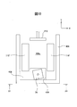
- FIG. 9 is a schematic front view of the electric discharge machine seen in the direction of arrow XI-XI in FIG. 8, and a view for explaining the electric discharge machining method of the present invention by the electric discharge machining system of FIG. 4.
- FIG. 2 is a schematic perspective view of a measurement probe attachment that can be replaced with a die-sinking electric discharge machining attachment in the electric discharge machine of FIG. 1.
- an electric discharge machine 10 includes a bed 26 serving as a base fixed to a floor surface of a factory, a table 28 fixed to an upper surface of the bed 26, an upper head 12 arranged above the table 28, and an upper head.
- Upper guide 14 which is held by 12 and guides the wire electrode 22, lower head 18 which is arranged so as to face the upper head 12, lower guide 20 which is held by the lower head 18 and guides the wire electrode 22, table 28 and lower head
- a processing tank 38 that surrounds the four enclosures of 18 is provided as a main component.
- the upper head 12 is provided so as to be movable relative to the bed 26 and the table 28 in three directions orthogonal to the X axis, the Y axis, and the Z axis.
- the upper head 12 is attached to a column (not shown) provided at the rear portion (back side) of the bed 26 and is reciprocally movable in the Y-axis direction (front-back direction, direction perpendicular to the paper surface in FIG. 1).
- a Y-axis slider (not shown), an X-axis slider (not shown) attached to the Y-axis slider so that it can reciprocate in the X-axis direction (horizontal direction), an X-axis that can reciprocate in the Z-axis direction (vertical direction) It can be attached to a Z-axis slider (quill) (not shown) attached to the slider.
- the X-axis slider, the Y-axis slider, and the Z-axis slider can be reciprocally driven in the X-axis, Y-axis, and Z-axis directions by an X-axis, Y-axis, and Z-axis feed device (not shown), respectively. ..
- the X-axis, Y-axis, and Z-axis feed devices are, for example, ball screws (not shown) extending in the respective directions of the X-axis, Y-axis, and Z-axis, and engaged with each of the ball screws.
- the servomotor can be connected to a control device that controls the electric discharge machine 10, for example, an NC device (not shown).
- a U axis and a V axis may be further provided for performing taper processing.
- the table 28 When viewed from above, the table 28 has a substantially rectangular frame shape that forms a concave space 28a surrounded by side walls perpendicular to the X axis and the Y axis.
- the lower head 18 is held by the support arm 16 that projects into the concave space 28a formed by the table 28.
- the support arm 16 can be attached to, for example, an X-axis slider.
- the support arm 16 extends from the rear of the table 28 into the concave space 28 a of the table 28.
- a power supply plate (not shown) for applying a predetermined potential to the wire electrode 22 is arranged inside the upper head 12.
- the power supply plate and the table 28 are connected to a discharge power source (not shown) for wire electric discharge machining, and a predetermined machining voltage is applied between the wire electrode 22 and the work 30 attached to the table 28.
- the support arm 16 is also provided with a bucket 36 formed of a bottomed member that opens upward.
- a bucket 36 formed of a bottomed member that opens upward.
- the wire electrode 22 is fed from a wire bobbin (not shown) by a wire electrode feeding device (not shown), and the inside of the Z-axis slider (quill), the upper head 12, the upper guide 14, and the lower part. After passing through the guide 20 and the lower head 18, the wire is collected by a wire collecting device or a wire collecting device (not shown).
- the wire electrode 22 is extended by the upper and lower guides 14 and 20 along the central axis O (Z-axis direction) of the electric discharge machine 10 while passing through the machining region which is the space between the upper and lower guides 14 and 20. Be guided to. That is, the central axis O defined by the upper and lower guides 14 and 20 serves as the traveling path of the wire electrode 22.
- the processing tank 38 is provided so as to be vertically movable in the Z-axis direction as shown by the arrow.
- the workpiece 30 mounted on the table 28 is moved upward as shown in FIG. 1 so that the workpiece 30 is immersed in the machining fluid 42 stored in the machining tank 38.
- the machining liquid 42 is discharged and then moved downward to enable the work 30 to be removed.
- a seal member 40 is provided on the side surface of the bed 26 so that the machining liquid 42 does not leak from between the machining tank 38 and the bed 26.
- the work 30 is placed on the upper surface of the table 28.
- the work 30 can be attached to the upper surface of the table 28 via the pallet 100, for example.
- the pallet 100 has a rectangular frame 102.
- An engaging portion 108 that engages with a transfer arm (for example, the transfer arm 214 of FIG. 4) of the work transfer device (for example, the work transfer device 210 of FIG. 4) projects from the upper surface of the frame 102.
- the engagement portion 108 can be formed from a pin having a head.
- a pair of work fixtures 106 is arranged inside the frame 102.
- the work fixture 106 extends between the long sides 104 of the frame 102 and is perpendicular to the long sides 104.
- the work fixture 106 holds the plate-shaped work 30 from both sides and fixes the work 30 to the frame 102.
- the pallet 100 can be attached to the table 28 so that the long side 104 extends in a direction perpendicular to the transfer arm of the work transfer device that engages with the engaging portion 108.
- the pallet 100 can be detachably attached to the table 28 via a pallet mount 110.
- the pallet mount 110 can be formed of a rectangular frame-shaped member having a size larger than that of the pallet 100.
- the pallet mount 110 has a plurality of chucks 112 for fixing the pallet 100, in the example of FIG. On the lower surface of the pallet 100, a grip portion (not shown) with which the chuck 112 is engaged and clamped is provided.
- the electric discharge machine 10 includes a small hole electric discharge machining attachment 45 as a die-sinking electric discharge machining attachment.
- the small-hole electric discharge machining attachment 45 has a main body 46 and an electrode holder 47 to which a pipe-shaped rod-shaped electrode 48 is attached as a carved electrode at the tip of the main body 46.
- the small hole electrical discharge machining attachment 45 is detachably attached to the side surface of the upper head 12 via the bracket 44 having the chuck 44a.
- an engaging portion (not shown) with which the chuck 44a is engaged is provided on the opposite side of the electrode holder 47.
- An electrode motor (not shown) for rotating the electrode holder 47 around the central axis O′ extending in the Z-axis direction may be provided in the main body 46.
- the central axis O′ of the small hole electric discharge machining attachment 45 and the central axis O of the electric discharge machine 10 are separated by a distance d.
- the bucket 36 is arranged so that its central portion substantially coincides with the central axis O'. Further, the bucket 36 has a size capable of receiving the falling core 34.
- a small hole electrical discharge machining unit is permanently installed so that it can move up and down, and it rises and retracts during wire electrical discharge machining. It is also possible to lower the hole electric discharge machining unit.
- the distance d is such that when the core 34 is completely separated from the outer peripheral portion 32 and the core 34 falls into the concave space 28a, the core 34 collides with the lower guide 20, the lower head 18, the support arm 16, and the like. It is a distance that allows it to fall into the bucket 36 without moving. This prevents the falling core 34 from damaging the lower guide 20, the lower head 18, the support arm 16 and the like. That is, the distance d is a distance that provides the position where the core 34 does not overlap the lower guide 20, the lower head 18, the support arm 16 and the like in the Z-axis direction.
- a connector 50 is also arranged on the bracket 44.
- the connector 52 of the small hole electric discharge machining attachment 45 is coupled to the connector 50 of the bracket 44.
- the small hole electric discharge machining attachment 45 is installed in the motor power source (not shown) for the electrode motor, the electric discharge power source (not shown) for small hole electric discharge machining, and the rod electrode 48. It is connected to a processing liquid supply source (not shown) for supplying the processing liquid.
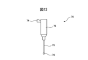
- the measurement probe attachment 70 shown in FIG. 13 is attached instead of the small hole electric discharge machining attachment 45, the measurement probe attachment 70 is connected to the control device of the electric discharge machine 10 by coupling the connectors 50 and 52. It may be done.
- the work 30 to which the wire electric discharge machining method of the present invention can be applied is formed of, for example, a plate-shaped member as shown in the upper part of FIG.
- the work 30 is wire-electric discharge machined along the cutout line 56, and the rectangular core 34 is cut out to manufacture a rectangular annular member as a product to be manufactured by the electric discharge machine 10. It is like this.
- the work 30 has an initial hole 54 penetrating in the Z-axis direction when attached to the table 28.
- the initial hole 54 serves as a starting point of wire electric discharge machining.
- the initial hole 54 can be processed by the small hole electric discharge machining attachment 45.
- the work 30 may be attached to the table 28 via the pallet 100 before the start of electric discharge machining.
- the wire electrode 22 is inserted from the upper guide 14 into the initial hole 54, and is sent to the wire collecting device through the lower guide 20, the lower head 18, and the support arm 16.
- the wire electrode 22 is inserted through the initial hole 54.
- the processing tank 38 moves upward, and the processing liquid 42 is supplied into the processing tank 38 from a processing liquid supply source (not shown).
- the working liquid 42 is supplied to the working tank 38 up to a height at which the work 30 attached to the table 28 is immersed in the working liquid 42.
- a pulse voltage is applied from the machining power supply between the wire electrode 22 and the table 28.
- a discharge is generated between the work 30 and the wire electrode 22, and the material of the work 30 is scraped off by the discharge.
- the wire electrode 22 moves relative to the workpiece 30 along the cutout line 56 from the machining start point, the initial hole 54 to the machining end point 57, as shown in the upper part of FIG.
- the cutout line 56 is an open line, and when the wire electric discharge machining is completed, an uncut portion 58 remains between the core 34 and the outer peripheral portion 32.
- the core 34 is connected to the outer peripheral portion 32 by the uncut portion 58.
- the supply of the wire electrode 22 is stopped and the wire electrode 22 is cut by a wire cutting machine (not shown).
- the portion of the wire electrode 22 used for processing is collected by the wire collecting device.
- the upper head 12 and the lower head 18 are fed to the work 30 along the X axis and the Y axis, and the rod-shaped electrode 48 is arranged right above the uncut portion 58 in the Z axis direction.
- the rod-shaped electrode 48 makes a fine hole. 60 is formed and the uncut portion 58 is removed.
- the work 30 is divided into the core 34 and the outer peripheral portion 32 surrounding the core 34.
- the core 34 is separated from the outer peripheral portion 32 and falls into the bucket 36.
- the core 34 that has fallen into the bucket 36 can be discharged to the outside of the table 28 from, for example, an opening 28 b formed in the side wall of the table 28.
- the electric discharge machine 10 shown in FIG. 1 is a hybrid electric discharge machine capable of performing wire electric discharge machining and fine hole electric discharge machining.
- the electrical discharge machining method of the present invention can also be implemented by an electrical discharge machining system that combines a dedicated machine for wire electrical discharge machining and a dedicated machine for small hole electrical discharge machining.
- an electric discharge machining system 200 includes a wire electric discharge machine 300, a small hole electric discharge machine 400 as a die-sinking electric discharge machine, and at least one of which are arranged in a predetermined axial direction, for example, the X-axis direction.
- a wire electric discharge machine 300 three pallet stations 202, 204, 206, a wire electric discharge machine 300, a small hole electric discharge machine 400 as a die-sinking electric discharge machine, and a work moving between the pallet stations 202, 204, 206.
- the electric discharge machining system 200 includes a control device that controls the entire electric discharge machining system 200.
- the wire electric discharge machine 300 is a dedicated wire electric discharge machine, and is a bed (not shown) serving as a base fixed to the floor of the factory, a table 312 fixed to the upper surface of the bed, and a table 312 above the table.
- An upper head 302 arranged, an upper guide 304 held by the upper head 302 and guiding the wire electrode 22, a lower head 308 attached to a support arm 306 so as to face the upper head 302, and a wire electrode held by the lower head 308.
- a lower guide 310 that guides the table 22, a table 312, and a processing tank 314 that surrounds the lower head 308 are provided as main components.
- the lower head 308 is arranged in a concave space 312a formed by the table 312.
- the wire electric discharge machine 300 also includes a control device (not shown) that controls the operation of the wire electric discharge machine 300.
- the wire electrode 22 is guided by the upper and lower guides 304 and 308 so as to extend along the central axis O (Z-axis direction) of the wire electric discharge machine 300. That is, the central axis O defined by the upper and lower guides 304 and 308 serves as the traveling path of the wire electrode 22.
- the processing tank 314 is provided so as to be vertically movable in the Z-axis direction.
- the workpiece 30 mounted on the table 312 is moved upward as shown in FIG. 5 so that the workpiece 30 is immersed in the machining fluid 42 stored in the machining tank 314.
- the machining liquid 42 is discharged and then moved downward to enable the work 30 to be removed.
- a seal member (not shown) is provided on the side surface of the bed so that the machining liquid 42 does not leak from between the machining tank 314 and the bed.
- the fine hole electric discharge machine 400 mainly includes a die-sinking electrode head 402 that holds a hollow rod-shaped electrode 404 as a die-sinking electrode, a table 408 to which the work 30 is attached, and a machining tank 406 that surrounds the four circles of the table 408. It is equipped as an element.
- the electrode head 402 holds the rod-shaped electrode 404 so as to extend along the central axis O′ in the Z-axis direction.
- the work 30 is the lower guide 310 of the wire electric discharge machine 300, the lower head 308, the support arm. There is no overlap with 306 and the like in the Z-axis direction.
- the table 408 is attached to a bed (not shown) that is a base fixed to the floor of the factory.
- the table 408 of the small hole electric discharge machine 400 does not have a concave space like the concave space 312a of the table 312 of the wire electric discharge machine 300, but has a flat upper surface 408a.
- the pallet mount 110' is fixed to the upper surface 408a.
- the pallet mount is formed of a rectangular rod-shaped or plate-shaped member instead of the rectangular frame-shaped member shown in FIG. 4, and the chuck 112 is mounted on the upper surface.
- the processing tank 406 is vertically movable in the Z-axis direction.
- the workpiece 30 mounted on the table 408 is moved upward as shown in FIG. 6 so that the workpiece 30 is immersed in the machining liquid 42 stored in the machining tank 406.
- the machining liquid 42 is discharged and then moved downward to enable the work 30 to be removed.
- a seal member (not shown) is arranged on the side surface of the bed so that the machining liquid 42 does not leak from between the machining tank 406 and the bed.
- the work transfer device 210 has a transfer carriage 212.
- the carriage 212 is capable of reciprocating along a track 208 extending in the predetermined axial direction of the electric discharge machining system 200, that is, the X-axis direction in the example of FIG. 4, as indicated by an arrow C. Further, a pair of conveyances provided on the conveyance carriage 212 so as to be able to move forward and backward in the horizontal direction perpendicular to the track 208, that is, in the Y-axis direction in the example of FIG. 4 (arrow A), and move up and down in the Z-axis direction.
- An arm 214 is provided.
- a fork portion 214 a that can be engaged with the engaging portion 108 of the pallet 100 is provided at the tip of the transfer arm 214.
- the work transfer device 210 includes a control device (not shown) that controls the operation of the transfer carriage 212 and the operation of the transfer arm 214.
- the work transfer device 210 may be a trackless vehicle, an articulated robot
- the control device of the electric discharge machining system 200 is connected to the control device of the wire electric discharge machine 300, the control device of the small hole electric discharge machine 400, and the control device of the work transfer device 210, and the wire electric discharge machine 300, the small hole electric discharge machine 400 is connected.
- the operation of the work transfer device 210 can be coordinatedly controlled.
- the pallet stations 202, 204, and 206 can place the pallet 100 on which the unprocessed work is mounted and picked up by the work transfer device 210, or can receive the pallet 100 on which the processed work is installed from the work transfer device 210.
- the machined work carried to the pallet stations 202, 204, 206 can be removed from the pallet 100 by an operator and attached to the pallet 100 with the unmachined work.
- the electric discharge machining system 200 uses the plate-shaped work 30 as shown in FIG. 3, and a rectangular core 34 is cut off to form a rectangular ring shape as a product to be manufactured by the electric discharge machining system 200. It is designed to manufacture parts.
- the carrier carriage 212 moves along the track 208 and stops in front of one of the pallet stations 202, 204, 206 on which the pallet 100 with the unmachined work is placed.
- the pair of transfer arms 214 is moved in the Z-axis direction, and the fork portion 214a at the tip thereof is positioned at a height at which the fork portion 214a can engage with the engaging portion 108 of the pallet 100.
- the transfer arm 214 is advanced in the Y-axis direction to engage the fork portion 214a with the engaging portion 108 of the pallet 100.
- the transfer arm 214 is further moved in the Z-axis direction to separate the pallet 100 from the pallet stations 202, 204, 206 upward.
- the transfer arm 214 is retracted toward the transfer carriage 212 in the Y-axis direction.
- the carrier truck 212 moves along a track 208 to a predetermined position in front of the wire electric discharge machine 300.
- the transfer arm 214 advances in the Y-axis direction toward the wire electric discharge machine 300.
- the transfer arm 214 moves downward in the Z-axis direction and the pallet 100 is placed on the pallet mount 110'. ..
- the chuck 112 of the pallet mount 110' engages with the grip portion provided on the lower surface of the pallet 100 to clamp the grip portion.
- the transport arm 214 moves backward in the Y-axis direction toward the transport carriage 212.
- the work 30 mounted on the pallet 100 is carried by the work carrying device 210 from one of the pallet stations 202, 204, 206 to the wire electric discharge machine 300 and fixed to the table 312 via the pallet mount 110'. To be done.
- the unmachined work 30 is conveyed to the small hole electric discharge machine 400 to machine the initial hole 54.
- the wire electrode 22 is inserted from the upper guide 304 into the initial hole 54, and is sent to the wire collecting device through the lower guide 310 and the support arm 306 that supports the lower guide 310. Then, the processing tank 314 moves upward, and the processing liquid 42 is supplied into the processing tank 314 from a processing liquid supply source (not shown). The machining liquid 42 is supplied to the machining tank 314 up to the height at which the work 30 is immersed in the machining liquid 42 (FIG. 5 ). A pulse voltage is applied from the machining power supply between the wire electrode 22 and the table 312, and the material of the work 30 is scraped off by the discharge generated between the work 30 and the wire electrode 22. While the pulse voltage is being applied, as in the case of FIG.
- the wire electrode 22 is moved relative to the workpiece 30 along the cutout line 56 from the machining start point, the initial hole 54 to the machining end point 57.
- the X-axis, Y-axis, and Z-axis feed devices are controlled.
- the wire electrode 22 When the wire electrode 22 reaches the processing end point 57, the supply of the wire electrode 22 is stopped and the wire electrode 22 is cut by a wire cutting machine (not shown). The portion of the wire electrode 22 used for processing is collected by the wire collecting device. When the wire electric discharge machining is completed, an uncut portion 58 remains between the core 34 and the outer peripheral portion 32. The core 34 is connected to the outer peripheral portion 32 by one uncut portion 58.
- the empty carrier truck 212 moves to a predetermined position in front of the wire electric discharge machine 300, and the carrier arm 214 advances toward the wire electric discharge machine 300 in the Y-axis direction. Then, the fork portion 214a at the tip end engages with the engaging portion 108 of the pallet 100.
- the transfer arm 214 moves upward in the Z-axis direction, and the pallet 100 separates from the pallet mount 110'. The transfer arm 214 moves backward in the Y-axis direction toward the transfer carriage 212, and the workpiece 30 that has been processed by the wire electric discharge machine 300 is taken out of the wire electric discharge machine 300.
- the carrier truck 212 moves to a predetermined position in front of the small hole electric discharge machine 400.
- the transfer arm 214 advances in the Y-axis direction toward the small hole electric discharge machine 400.
- the transfer arm 214 moves downward in the Z-axis direction, and the pallet 100 is placed on the pallet mount 110'.
- the chuck 112 engages the grip portion of the pallet 100 and clamps the grip portion.
- the transport arm 214 moves backward in the Y-axis direction toward the transport carriage 212. In this way, the work 30 machined by the wire electric discharge machine 300 is conveyed from the wire electric discharge machine 300 to the small hole electric discharge machine 400, and is fixed to the table 408 via the pallet mount 110'.
- the engraving electrode head 402 is moved downward along the Z axis while applying a predetermined processing voltage between the rod-shaped electrode 404 and the work 30 (table 408), the space between the rod-shaped electrode 404 and the work 30 is reduced.
- the uncut portion 58 is removed by the discharge generated at.
- the core 34 is separated from the outer peripheral portion 32 and drops onto the upper surface 408a of the table 408, as shown in FIG. According to this example, since the fall distance is short, there is no problem even when a heavy core or an imbalanced core having an irregular shape is generated.
- the rod-shaped electrode 404 is consumed, it is replaced with a new rod-shaped electrode 404 by an automatic electrode exchange device (not shown).
- the contact detection function between the rod-shaped electrode 404 and the work 30 that the small hole electric discharge machine 400 originally has is used to automatically detect whether the core 34 has been completely separated from the outer peripheral portion 32.
- the detection method is as follows. If the core 34 is lowered and no contact is detected at that time, it can be confirmed that the core 34 has been separated.
- the engraving electrode head 402 moves upward in the Z-axis direction and separates from the table 408 and the pallet 100.
- the transfer arm 214 of the work transfer device 210 advances in the Y-axis direction toward the small hole electric discharge machine 400, and the fork part 214a engages with the engaging part 108 of the pallet 100.
- the transfer arm 214 moves upward in the Z-axis direction and the pallet 100 separates from the pallet mount 110', as shown in FIG.
- the transfer arm 214 retracts in the Y-axis direction toward the transfer carriage 212, and the outer peripheral portion 32 is taken out from the small hole electric discharge machine 400 together with the pallet 100.
- the separated core 34 is left on the upper surface of the table 408 (see FIGS. 7 and 9).
- the outer peripheral portion 32 separated from the core 34 in the fine hole electric discharge machine 400 is again conveyed to the wire electric discharge machine 300 by the conveyance carriage 212 as necessary, and finish machining of the small hole electric discharge machined portion is performed. Is given. After that, the processed work 30 is conveyed together with the pallet 100 to the pallet station 202, 204, or 206 that is empty.
- the outer peripheral portion 32 can be removed from the pallet 100 by, for example, an operator or a dedicated removing device (not shown).
- the sweeper 412 which is provided so as to be movable along the upper surface of the table 408, advances in the Y-axis direction across the machining region where the electric discharge machining is performed by the rod-shaped electrode 404, as indicated by arrow E in FIG. ,
- the core 34 placed on the upper surface 408a of the table 408 is dropped into the pocket portion 410 formed in the table 408 (see FIGS. 10 and 11) or moved out of the movable range.
- the sweeper 412 retracts in the Y-axis direction to the outside of the processing area for the next process.
- the sweeper 412 can be mounted on the X-axis slider when necessary by using a mechanism similar to the automatic electrode exchange function, and can be driven by an X-axis or Y-axis feed operation.
- the uncut portion 58 is removed by the fine hole electrical discharge machining, but the present invention is not limited to this, and for example, it is removed by the die sinking electrical discharge machining by the rib electrode 60 as shown in FIG. You may.
- the rib electrode 60 is attached to the side surface of the upper head 12 via a die-sinking electric discharge machining attachment (not shown) to which the rib electrode 60 is attached instead of the small hole electric discharge machining attachment 45. be able to.
- a die-sinking electric discharge machine (not shown) having the rib electrode 60 can be installed.
- the electrode is not limited to a rib electrode having a gradient, and may be a columnar shape such as a rod shape or a thin plate shape, as long as the uncut portion 58 can be removed by electric discharge machining.
- the measurement probe attachment 70 can be attached instead of the small hole electrical discharge machining attachment 45.
- the measurement probe attachment 70 has a connector 74 detachably coupled to the connector 50 on the side surface of the main body 72, and a measurement probe 76 at the tip of the main body 72.
- the measurement probe attachment 70 attached to the side surface of the upper head 12 is moved with respect to the work 30 by the X-axis, Y-axis, and Z-axis feeding device of the electric discharge machine 10, and the tip 78 of the measurement probe 76 is moved to the work 30.
- the coordinates when the surface is contacted can be read from the X-axis, Y-axis, and Z-axis digital scales of the electric discharge machine 10 to measure the dimensions of the work 30.
- the small hole electric discharge machining attachment 45 and the measurement probe attachment 70 can be automatically performed by an attachment exchange device such as a robot hand (not shown).
- the present invention is not limited to this and is applied to any electric discharge machine that produces a core. can do.
- the central axis O that defines the traveling path of the wire electrode 22 extends in the Z-axis direction, but the present invention is not limited to this and may be inclined with respect to the Z-axis. Good. That is, the upper guide 14 and the lower guide 20 do not have to be aligned with each other in the Z-axis direction.
- the central axis O'of the small hole electrical discharge machining attachment 45 is also inclined so as to be parallel to the central axis O defining the traveling path, and the rod-shaped electrode 48 is also attached to the work 30 along the inclined central axis O'. It can be moved relative to each other.
- the processing tank has been described as a lifting type, it may be a door opening/closing type.
- the present invention is a method for machining the uncut portion of the core by wire electrical discharge machining without damaging the lower head below the core, as a method for machining fine hole electrical discharge with a rod-shaped electrode or shape engraving with a rib electrode.
- Non-contact machining such as electrical discharge machining is used.
- the power supply device for small-hole electric discharge machining or die-sinking electric discharge machining can be shared with the power supply device for wire electric discharge machining, so that the entire machine does not have to be complicated.
- a laser machining attachment may be used, or if a laser machining machine is included as one machining machine of the electric discharge machining system, the uncut portion may be cut off by laser machining.
Landscapes
- Chemical & Material Sciences (AREA)
- Chemical Kinetics & Catalysis (AREA)
- Electrochemistry (AREA)
- Engineering & Computer Science (AREA)
- Mechanical Engineering (AREA)
- Electrical Discharge Machining, Electrochemical Machining, And Combined Machining (AREA)
Abstract
ワーク(30)を中子(34)と、該中子を包囲する外周部分(32)とに分離する放電加工方法において、上ガイド(14)と下ガイド(20)の間で所定の走行経路に沿って走行するワイヤ電極(22)にワークに対して所定の電圧を印加し、走行経路に対して垂直な方向にワイヤ電極をワークに対して相対移動させてワイヤ放電加工を行い、中子と外周部材とが1か所の未切断部分(58)によって連結されるように相対移動を停止し、中子と下ガイドとが上下方向に重なり合わないように、ワークを上ガイドおよび下ガイドに対して相対移動した後に、形彫り放電加工によって未切断部分を除去するようにした。
Description
本発明は、ワイヤ放電加工機でワークを加工する際に生ずる中子を、ワークから分離できるようにした放電加工方法、該放電加工方法を実施する放電加工機および放電加工システムに関する。
ワイヤ放電加工機では、加工プロセスが終了するときに、ワークから中子が分離、落下する。落下する中子は、ワークの下側に配置されワイヤ電極を案内する下ガイドに衝突して、下ガイドを損傷することがある。落下する中子にワイヤ電極が引っ掛かり、ワイヤ電極が不定形に切断されることもある。また、ワークが損傷することもある。
こうした問題を解決するために、従来から種々の中子処理方法が開発されてきている。例えば、特許文献1には、切り抜き線を境にして互いに隣接している中子とワークとを磁石に吸着させた状態で、ワイヤ電極とワークとを相対的に移動させ、ワイヤ放電加工で中子をワークから完全に切断するようにしたワイヤ放電加工機の中子処理方法が記載されている。
特許文献1の中子処理方法では、例えば磁石に吸着しない材料でワイヤ放電加工を行う場合に、中子処理を行えなくなる。そうした場合には、作業者が手動で中子をワークから分離しなければならない問題がある。
本発明は、こうした従来技術の問題を解決することを技術課題としており、中子の大きさや形状、重量、材質によらず、中子を迅速にワークから切り離し、また、中子の落下により下ガイドが損傷したり、ワイヤ電極が異常切断されることを防止した放電加工方法および該放電加工方法を実施する放電加工機および放電加工システムを提供することを目的としている。
上述の目的を達成するために、本発明によれば、ワークを中子と、該中子を包囲する外周部分とに分離する放電加工方法において、ワイヤ電極を上ガイドと下ガイドの間で所定の走行経路に沿って走行可能に張り渡す工程と、ワイヤ電極とワークとの間に所定の電圧を印加する工程と、ワイヤ電極を走行経路に沿って走行させつつ、ワイヤ電極とワークとを相対移動させ、ワイヤ電極とワークとの間に生じる放電現象によってワークの材料が除去されるようにワイヤ放電加工を行う工程と、ワイヤ放電加工によってワークに形成された中子と外周部分とが、未切断部分によって連結されるように、相対移動を停止する工程と、中子と下ガイドとが上下方向に重なり合わないように、ワークを上ガイドおよび下ガイドに対して相対移動する工程と、走行経路外でワイヤ放電加工以外の加工によって、未切断部分を除去する工程とを含んで成る放電加工方法が提供される。
更に、本発明によれば、前記放電加工方法を実施する放電加工機において、凹空間を有しワークを取り付けるテーブルと、テーブルの上方に配置され、上ガイドを有した上ヘッドと、上ヘッドに対面するようにテーブルの凹空間内に配置され、下ガイドを有した下ヘッドと、上ヘッドの側面に取り付けた形彫り放電加工アタッチメントとを具備し、形彫り放電加工アタッチメントが、ワイヤ電極の走行経路に平行な方向に延びる形彫り電極を有し、形彫り放電加工によって未切断部分を除去するようにした放電加工機が提供される。
更に、本発明によれば、前記放電加工方法を実施する放電加工機において、凹空間を有しワークを取り付けるテーブルと、テーブルの上方に配置され、上ガイドを有した上ヘッドと、上ヘッドに対面するようにテーブルの凹空間内に配置され、下ガイドを有した下ヘッドとを有した少なくとも1つのワイヤ放電加工機と、ワークを取り付けるテーブルと、テーブルの上方に配置されワイヤ電極の走行経路に平行な方向に延びる形彫り電極を有した少なくとも1つの形彫り放電加工機と、を具備し、前記ワイヤ放電加工で加工した未切断部分を有するワークを前記形彫り放電加工機へ移載し、形彫り放電加工によって未切断部分を除去するようにした放電加工システムが提供される。
本発明よれば、中子と下ガイドとが上下方向に重なり合わないように、ワークを上ガイドおよび下ガイドに対して相対移動した後に、形彫り放電加工によって、未切断部分を除去するようにしたので、中子の落下により下ガイドが損傷することが防止される。また、中子の大きさや形状、重量、材質によらず、中子を迅速、確実にワークから切り離すことができる。
以下、図1を参照して、本発明の放電加工方法を実施するワイヤ放電加工機(以下、単に放電加工機とする)の一例を説明する。図1において、放電加工機10は、工場の床面に固定される基台となるベッド26、ベッド26の上面に固定されるテーブル28、テーブル28の上方に配置される上ヘッド12、上ヘッド12に保持されワイヤ電極22を案内する上ガイド14、上ヘッド12に対面するように配置される下ヘッド18、下ヘッド18に保持されワイヤ電極22を案内する下ガイド20、テーブル28および下ヘッド18の四囲を包囲する加工槽38を主要な構成要素として具備している。
上ヘッド12はベッド26およびテーブル28に対してX軸、Y軸、Z軸の直交3軸方向に相対移動可能に設けられている。例えば、上ヘッド12は、ベッド26の後方部分(奥側)に設けられるコラム(図示せず)、Y軸方向(前後方向、図1では紙面に垂直な方向)に往復可能にコラムに取り付けられたY軸スライダ(図示せず)、X軸方向(左右方向)に往復可能にY軸スライダに取り付けられたX軸スライダ(図示せず)、Z軸方向(上下方向)に往復可能にX軸スライダに取り付けられたZ軸スライダ(クイル)(図示せず)に取り付けることができる。
前記X軸スライダ、Y軸スライダ、Z軸スライダは、X軸、Y軸、Z軸の送り装置(図示せず)によって、夫々、X軸、Y軸、Z軸方向に往復駆動することができる。X軸、Y軸、Z軸の送り装置は、例えば、X軸、Y軸、Z軸の各方向に延設されたボールねじ(図示せず)、該ボールねじの各々に係合し、X軸スライダ、Y軸スライダ、Z軸スライダに取り付けられたナット(図示せず)、X軸、Y軸、Z軸のボールねじの一端に結合されたX軸、Y軸、Z軸のサーボモータを含むことができる。サーボモータは、放電加工機10を制御する制御装置、例えばNC装置(図示せず)に接続することができる。テーパ加工を行うために、更にU軸、V軸を備えていてもよい。
テーブル28は上方から見ると、X軸、Y軸に垂直な側壁によって包囲された凹空間28aを形成する略矩形の枠形状をなしている。下ヘッド18は、テーブル28が形成する凹空間28a内に突出した支持アーム16に保持されている。支持アーム16は、例えばX軸スライダに取り付けることができる。支持アーム16はテーブル28の後方からテーブル28の凹空間28a内まで延設されている。上ヘッド12内には、ワイヤ電極22に所定の電位を与える給電板(図示せず)が配設されている。給電板とテーブル28は、ワイヤ放電加工用の放電電源(図示せず)に接続されており、ワイヤ電極22とテーブル28に取り付けられたワーク30との間に所定の加工電圧が印加される。
支持アーム16には、また、上方に開口した有底状の部材より成るバケット36が配設されている。支持アームをX軸スライダに取り付けることによって、下ヘッド18は、上ヘッド12と共に、テーブル28およびテーブル28に取り付けられたワーク30に対して相対移動する。
ワーク30の加工中、ワイヤ電極22は、ワイヤ電極送り装置(図示せず)によって、ワイヤボビン(図示せず)から繰り出され、Z軸スライダ(クイル)の内部、上ヘッド12、上ガイド14、下ガイド20、下ヘッド18を順次通過して、ワイヤ回収装置またはワイヤ回収装置(図示せず)に回収される。ワイヤ電極22は、上下ガイド14、20の間の空間である加工領域を通過する間、上下ガイド14、20によって、放電加工機10の中心軸線O(Z軸方向)に沿って延在するように案内される。つまり、上下ガイド14、20によって規定される中心軸線Oがワイヤ電極22の走行経路となる。
加工槽38は、矢印で示すように、Z軸方向に上下動可能に設けられている。放電加工中は、図1に示すように上動して、テーブル28に取り付けられたワーク30が加工槽38内に貯留された加工液42中に浸漬されるようにする。放電加工が終了して、ワーク30をテーブル28から取り外す際には、加工液42を排出後に下動して、ワーク30の取り外し作業を可能とする。ベッド26の側面にはシール部材40が配設されており、加工槽38とベッド26の間から加工液42が漏洩しないようになっている。
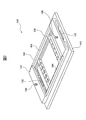
テーブル28の上面にワーク30が載置される。ワーク30は、例えば、パレット100を介してテーブル28の上面に取り付けることができる。図2を参照すると、一例として、パレット100は矩形のフレーム102を有している。フレーム102の上面には、ワーク搬送装置(例えば、図4のワーク搬送装置210)の搬送アーム(例えば、図4の搬送アーム214)に係合する係合部108が突出している。係合部108は、頭部を有したピンから形成することができる。
フレーム102の内側には、一対のワーク固定具106が配設されている。ワーク固定具106は、フレーム102の長辺104の間で長辺104に対して垂直に延設されている。ワーク固定具106は、板状のワーク30を両側から挟持して、該ワーク30をフレーム102に固定する。
パレット100は、係合部108に係合するワーク搬送装置の搬送アームに対して長辺104が垂直な方向に延在するように、テーブル28に取り付けることができる。パレット100は、パレット取付台110を介してテーブル28に着脱可能に取り付けるようにできる。パレット取付台110は、パレット100よりも大きな寸法の矩形のフレーム状の部材から形成することができる。パレット取付台110は、パレット100を固定する複数の、図2の例では2つのチャック112を有している。パレット100の下面には、チャック112が係合、クランプするグリップ部(図示せず)が設けられている。
また、放電加工機10は、形彫り放電加工アタッチメントとして細穴放電加工アタッチメント45を備えている。細穴放電加工アタッチメント45は、本体46と、該本体46の先端に形彫り電極としてパイプ状の棒状電極48を取り付ける電極ホルダ47とを有している。細穴放電加工アタッチメント45は、チャック44aを有したブラケット44を介して、上ヘッド12の側面に着脱可能に取り付けられる。細穴放電加工アタッチメント45において、電極ホルダ47の反対側には、チャック44aが係合する係合部(図示せず)が設けられている。本体46内には電極ホルダ47をZ軸方向に延びる中心軸線O′周りに旋回させる電極モータ(図示せず)が配設されていてもよい。細穴放電加工アタッチメント45を上ヘッド12に取り付けたとき、細穴放電加工アタッチメント45の中心軸線O′と、放電加工機10の中心軸線Oとは、距離dを以て離間している。バケット36は、その中心部が概ね中心軸線O′に一致するように配置されている。また、バケット36は、落下する中子34を受容可能な大きさを有している。
着脱可能な細穴放電加工アタッチメントに代えて、細穴放電加工ユニットが上下進退可能に常設され、ワイヤ放電加工中は上昇して退避しており、未切断部分を58を除去するときに、細穴放電加工ユニットを下降させる構成にすることもでできる。
距離dは、中子34が外周部分32から完全に分離され、中子34が凹空間28a内に落下したときに、中子34が、下ガイド20、下ヘッド18、支持アーム16等に衝突することなく、バケット36内に落下できる距離である。これにより、落下する中子34によって下ガイド20、下ヘッド18、支持アーム16等が損傷することが防止される。つまり、距離dは、中子34が、下ガイド20、下ヘッド18、支持アーム16等に対してZ軸方向に重なり合わない位置を提供する距離である。
ブラケット44には、また、コネクタ50が配設されている。細穴放電加工アタッチメント45をブラケット44に取り付けると、細穴放電加工アタッチメント45のコネクタ52がブラケット44のコネクタ50に結合される。コネクタ50、52が結合することによって、細穴放電加工アタッチメント45は、電極モータのためのモータ電源(図示せず)、細穴放電加工用の放電電源(図示せず)、棒状電極48内に加工液を供給する加工液供給源(図示せず)に接続される。また、細穴放電加工アタッチメント45に代えて、図13に示す測定プローブアタッチメント70を取り付ける場合には、コネクタ50、52が結合することによって、測定プローブアタッチメント70が放電加工機10の制御装置に接続されるようにしてもよい。
以下、図3を参照して、放電加工機10の作用(放電加工方法)を説明する。
本発明のワイヤ放電加工方法を適用可能なワーク30は、例えば、図3の上段に示すように、板状の部材より形成されている。特に、本実施形態では、ワーク30は、切り抜き線56に沿ってワイヤ放電加工を行い、矩形の中子34を切り取ることによって、放電加工機10が製造すべき製品として矩形の環状部材を製作するようになっている。ワーク30は、テーブル28に取り付けたときに、Z軸方向に貫通するイニシャルホール54を有している。イニシャルホール54はワイヤ放電加工の開始点となる。なお、イニシャルホール54は、細穴放電加工アタッチメント45で加工できる。
本発明のワイヤ放電加工方法を適用可能なワーク30は、例えば、図3の上段に示すように、板状の部材より形成されている。特に、本実施形態では、ワーク30は、切り抜き線56に沿ってワイヤ放電加工を行い、矩形の中子34を切り取ることによって、放電加工機10が製造すべき製品として矩形の環状部材を製作するようになっている。ワーク30は、テーブル28に取り付けたときに、Z軸方向に貫通するイニシャルホール54を有している。イニシャルホール54はワイヤ放電加工の開始点となる。なお、イニシャルホール54は、細穴放電加工アタッチメント45で加工できる。
放電加工の開始前に、ワーク30がパレット100を介してテーブル28に取り付けられてもよい。ワイヤ電極22が、上ガイド14からイニシャルホール54に挿通され、下ガイド20、下ヘッド18、支持アーム16を通ってワイヤ回収装置まで送られる。イニシャルホール54にワイヤ電極22が挿通される。次いで、加工槽38が上動し、加工液供給源(図示せず)から加工槽38内に加工液42が供給される。加工液42は、テーブル28に取り付けられたワーク30が加工液42に浸漬される高さまで加工槽38に供給される。
次いで、ワイヤ電極22とテーブル28との間に加工用電源からパルス電圧が印加される。これによりワーク30とワイヤ電極22との間に放電が発生し、放電によってワーク30の材料が削り取られる。パルス電圧が印加される間、ワイヤ電極22は、図3の上段に図示するように、加工開始点であるイニシャルホール54から加工終点57まで、切り抜き線56に沿ってワーク30に対して相対移動するように、X軸、Y軸、Z軸の送り装置が制御される。切り抜き線56は開いた線であり、ワイヤ放電加工が終了したときに、中子34と、外周部分32との間には未切断部分58が残る。未切断部分58によって、中子34は外周部分32に連結されている。
ワイヤ電極22が加工終点57に到達すると、ワイヤ電極22の供給が停止されると共に、ワイヤ電極22はワイヤ切断機(図示せず)によって切断される。加工に使用したワイヤ電極22の部分はワイヤ回収装置に回収される。次いで、上ヘッド12および下ヘッド18がワーク30に対してX軸、Y軸に沿って送られ、棒状電極48が、Z軸方向に未切断部分58の真上に配置される。
次いで、図3の中段に示すように、棒状電極48とテーブル28との間に所定の加工電圧を印加しながら、上ヘッド12をZ軸に沿って下動させると、棒状電極48によって細穴60が形成され、未切断部分58が除去される。未切断部分58が除去されると、ワーク30は、中子34と、該中子34を包囲する外周部分32とに分割される。中子34は、図3の下段に示すように、外周部分32から切り離されバケット36内に落下する。バケット36内に落下した中子34は、例えば、テーブル28の側壁に形成された開口部28bからテーブル28の外部に排出することができる。
次に、図4を参照して、本発明の放電加工方法を実施可能な放電加工システムを説明する。図1に示す放電加工機10は、ワイヤ放電加工と細穴放電加工とを行うことが可能なハイブリッド型の放電加工機である。然しながら、本発明の放電加工方法は、ワイヤ放電加工の専用機と、細穴放電加工の専用機とを組み合わせた放電加工システムによっても実施可能である。
図4において、放電加工システム200は、所定の軸線方向、例えばX軸方向に配設された、ワイヤ放電加工機300と、形彫り放電加工機としての細穴放電加工機400と、少なくとも1つの、図4の例では3つのパレットステーション202、204、206と、ワイヤ放電加工機300、形彫り放電加工機としての細穴放電加工機400、パレットステーション202、204、206の間を移動するワーク搬送装置210とを備えている。放電加工システム200は、該放電加工システム200の全体を制御する制御装置を備えている。
ワイヤ放電加工機300は、ワイヤ放電加工専用機であって、工場の床面に固定される基台となるベッド(図示せず)、ベッドの上面に固定されるテーブル312、テーブル312の上方に配置される上ヘッド302、上ヘッド302に保持されワイヤ電極22を案内する上ガイド304、上ヘッド302に対面するように支持アーム306に取り付けられた下ヘッド308、下ヘッド308に保持されワイヤ電極22を案内する下ガイド310、テーブル312および下ヘッド308の四囲を包囲する加工槽314を主要な構成要素として具備している。下ヘッド308は、テーブル312が形成する凹空間312a内に配置されている。ワイヤ放電加工機300は、また、該ワイヤ放電加工機300の動作を制御する制御装置(図示せず)を備えている。ワイヤ電極22は、上下ガイド304、308によって、ワイヤ放電加工機300の中心軸線O(Z軸方向)に沿って延在するように案内される。つまり、上下ガイド304、308によって規定される中心軸線Oがワイヤ電極22の走行経路となる。
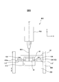
加工槽314は、Z軸方向に上下動可能に設けられている。放電加工中は、図5に示すように上動して、テーブル312に取り付けられたワーク30が加工槽314内に貯留された加工液42中に浸漬されるようにする。放電加工が終了して、ワーク30をテーブル312から取り外す際には、加工液42を排出後に下動して、ワーク30の取り外し作業を可能とする。図1の放電加工機10と同様に、ベッドの側面にはシール部材(図示せず)が配設されており、加工槽314とベッドの間から加工液42が漏洩しないようになっている。
細穴放電加工機400は、形彫り電極としての中空の棒状電極404を保持する形彫り電極ヘッド402と、ワーク30を取り付けるテーブル408と、テーブル408の四囲を包囲する加工槽406を主要な構成要素として具備している。電極ヘッド402は、棒状電極404がZ軸方向の中心軸線O′に沿って延在するように保持する。本例では、図1の実施形態とは異なり、細穴放電加工機400において未切断部分58を除去する際に、ワーク30が、ワイヤ放電加工機300の下ガイド310、下ヘッド308、支持アーム306等に対してZ軸方向に重なり合うことはない。
テーブル408は、工場の床面に固定される基台となるベッド(図示せず)に取り付けられている。細穴放電加工機400のテーブル408は、ワイヤ放電加工機300のテーブル312の凹空間312aのような凹空間はなく、平坦な上面408aを有している。上面408aにパレット取付台110′が固定される。本例では、パレット取付台は、図4に示した矩形のフレーム状の部材ではなく、矩形の棒状または板状の部材から形成され、上面にチャック112が取り付けられている。
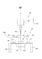
加工槽406は、Z軸方向に上下動可能に設けられている。放電加工中は、図6に示すように上動して、テーブル408に取り付けられたワーク30が加工槽406内に貯留された加工液42中に浸漬されるようにする。放電加工が終了して、ワーク30をテーブル408から取り外す際には、図7、9に示すように、加工液42を排出後に下動して、ワーク30の取り外し作業を可能とする。図1の放電加工機10と同様に、ベッドの側面にはシール部材(図示せず)が配設されており、加工槽406とベッドの間から加工液42が漏洩しないようになっている。
ワーク搬送装置210は搬送台車212を有している。搬送台車212は、矢印Cで示すように、放電加工システム200の前記所定の軸線方向、図4の例では、X軸方向に延設された軌道208に沿って往復移動可能となっている。また、搬送台車212には、軌道208に対して垂直な水平方向、図4の例ではY軸方向に進退可能(矢印A)、かつ、Z軸方向に上下動可能に設けられた一対の搬送アーム214が設けられている。搬送アーム214の先端には、パレット100の係合部108に係合可能なフォーク部214aが設けられている。ワーク搬送装置210は、搬送台車212の動作および搬送アーム214の動作を制御する制御装置(図示せず)を備えている。ワーク搬送装置210は、無軌道車や多関節ロボット等であってもよい。
放電加工システム200の制御装置をワイヤ放電加工機300の制御装置、細穴放電加工機400の制御装置およびワーク搬送装置210の制御装置に接続し、ワイヤ放電加工機300、細穴放電加工機400およびワーク搬送装置210の動作を協調制御するようにできる。
パレットステーション202、204、206は、未加工ワークを取り付けたパレット100を載置して、ワーク搬送装置210が取り上げたり、加工済ワークを取り付けたパレット100をワーク搬送装置210から受け取ることができる。パレットステーション202、204、206へ搬送された加工済ワークは、オペレータによって、パレット100から取り外され、未加工ワークが空いたパレット100に取り付けられるようにできる。
以下、図5~図10を参照して、放電加工システム200の作用(放電加工方法)を説明する。
以下の説明では、放電加工システム200は、図3に示したような板状のワーク30が用いられ、矩形の中子34を切り取ることによって、放電加工システム200が製造すべき製品として矩形の環状部材を製作するようになっている。
放電加工の開始前に、搬送台車212は、軌道208に沿って移動し、未加工ワークを取り付けたパレット100が載置されているパレットステーション202、204、206の1つの前に停止する。一対の搬送アーム214をZ軸方向に移動させて、その先端のフォーク部214aがパレット100の係合部108に係合可能な高さに位置決めする。搬送アーム214をY軸方向に前進させ、フォーク部214aをパレット100の係合部108に係合させる。搬送アーム214を更にZ軸方向に上動させて、パレット100をパレットステーション202、204、206から上方に離反させる。搬送アーム214を搬送台車212側にY軸方向に後退させる。
次いで、搬送台車212は、ワイヤ放電加工機300の前の所定位置へ軌道208に沿って移動する。搬送アーム214がワイヤ放電加工機300へ向けてY軸方向に前進する。パレット100が、テーブル312に固定されているパレット取付台110′の上方に配置されると、搬送アーム214がZ軸方向に下動して、パレット100がパレット取付台110′に載置される。パレット取付台110′のチャック112がパレット100の下面に設けられているグリップ部と係合し、該グリップ部をクランプする。次いで、搬送アーム214が、搬送台車212へ向けてY軸方向に後退する。こうして、パレット100に取り付けられたワーク30が、ワーク搬送装置210によってパレットステーション202、204、206の1つから、ワイヤ放電加工機300へ搬送され、パレット取付台110′を介してテーブル312に固定される。ここでは詳述しなが、最初に未加工ワーク30を細穴放電加工機400に搬送して、イニシャルホール54が加工される。
ワイヤ電極22が、上ガイド304からイニシャルホール54に挿通され、下ガイド310、下ガイド310を支持する支持アーム306を通ってワイヤ回収装置まで送られる。次いで、加工槽314が上動し、加工液供給源(図示せず)から加工槽314内に加工液42が供給される。加工液42は、ワーク30が加工液42に浸漬される高さまで加工槽314に供給される(図5)。ワイヤ電極22とテーブル312との間に加工用電源からパルス電圧が印加されワーク30とワイヤ電極22との間に発生する放電によってワーク30の材料が削り取られる。パルス電圧が印加される間、図3の場合と同様に、ワイヤ電極22が、加工開始点であるイニシャルホール54から加工終点57まで、切り抜き線56に沿ってワーク30に対して相対移動するように、X軸、Y軸、Z軸の送り装置が制御される。
ワイヤ電極22が加工終点57に到達すると、ワイヤ電極22の供給が停止されると共に、ワイヤ電極22はワイヤ切断機(図示せず)によって切断される。加工に使用したワイヤ電極22の部分はワイヤ回収装置に回収される。ワイヤ放電加工が終了したときに、中子34と、外周部分32との間には未切断部分58が残る。1つの未切断部分58によって、中子34は外周部分32に連結されている。
こうして、ワイヤ放電加工機300における加工が終了すると、空の搬送台車212がワイヤ放電加工機300の前の所定位置に移動し、搬送アーム214がワイヤ放電加工機300へ向けてY軸方向に前進し、先端のフォーク部214aがパレット100の係合部108に係合する。次いで、パレット取付台110′のチャック112がアンクランプした後に搬送アーム214がZ軸方向に上動し、パレット100がパレット取付台110′から離反する。搬送アーム214が搬送台車212へ向けてY軸方向に後退し、ワイヤ放電加工機300における加工を終了したワーク30がワイヤ放電加工機300から取り出される。
次いで、搬送台車212は、細穴放電加工機400の前の所定位置に移動する。搬送アーム214が細穴放電加工機400へ向けてY軸方向に前進する。パレット100が、テーブル408に固定されているパレット取付台110′の上方に配置されると、搬送アーム214がZ軸方向に下動して、パレット100がパレット取付台110′に載置され、チャック112がパレット100のグリップ部と係合し、該グリップ部をクランプする。次いで、搬送アーム214が、搬送台車212へ向けてY軸方向に後退する。こうして、ワイヤ放電加工機300により加工されたワーク30が、ワイヤ放電加工機300から細穴放電加工機400へ搬送され、パレット取付台110′を介してテーブル408に固定される。
次いで、棒状電極404とワーク30(テーブル408)との間に所定の加工電圧を印加しながら、形彫り電極ヘッド402をZ軸に沿って下動させると、棒状電極404とワーク30との間に生成される放電によって、未切断部分58が除去される。未切断部分58が除去されると、中子34は、図6に示すように、外周部分32から切り離されテーブル408の上面408aに落下する。本例によれば、落下距離が短いので重い中子や、異形状のアンバランスな形状の中子が生じる場合でも問題を生じることがない。なお、棒状電極404が消耗したときは、自動電極交換装置(図示せず)により新しい棒状電極404と交換される。
細穴放電加工機400が元来有している棒状電極404とワーク30との接触検知機能を利用して、中子34が外周部分32から完全に切り離されたかを自動的に検出する。その検出方法は、中子34がテーブル408の上面408aに落下して生じる外周部分32の上面から中子34の上面までの段差空間内に、棒状電極404の先端が位置するまで上ヘッド402を下降させ、そのとき接触を検知しなければ、中子34が切り離されたと確認するようにできる。
次いで、形彫り電極ヘッド402がZ軸方向に上動してテーブル408およびパレット100から離反する。形彫り電極ヘッド402が上動した後、ワーク搬送装置210の搬送アーム214が細穴放電加工機400へ向けてY軸方向に前進し、フォーク部214aがパレット100の係合部108に係合する。パレット取付台110′のチャック112がアンクランプした後、図7に示すように、搬送アーム214がZ軸方向に上動し、パレット100がパレット取付台110′から離反する。搬送アーム214が搬送台車212へ向けてY軸方向に後退し、外周部分32がパレット100と共に細穴放電加工機400から取り出される。分離された中子34は、テーブル408の上面に残される(図7、9参照)。
細穴放電加工機400おいて中子34と分離された外周部分32は、必要に応じて、搬送台車212によって再度ワイヤ放電加工機300に搬送され、細穴放電加工された部分の仕上げ加工が施される。その後、加工の終ったワーク30は、パレットステーション202、204、206のうち空いているパレットステーションにパレット100と共に搬送される。外周部分32は、例えば、オペレータによって、或いは、専用の取外装置(図示せず)によってパレット100から取り外すようにできる。
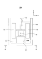
次いで、テーブル408の上面に沿って移動可能に設けられたスイーパ412が、図8において矢印Eで示すように、棒状電極404による放電加工が行われる加工領域を横断してY軸方向に前進し、テーブル408の上面408aに載置されている中子34を、テーブル408に形成されたポケット部410内に落下させる(図10、11参照)、または可動範囲外へ移動させる。その後、スイーパ412は、図10、11に示すように、次工程のために加工領域外へY軸方向に後退する。スイーパ412は、自動電極交換機能と同様の機構を用いて、必要なときにX軸スライダに装着され、X軸やY軸の軸送り動作で駆動させることもできる。
既述の実施形態では、未切断部分58は細穴放電加工によって除去されていたが、本発明はこれに限定されず、例えば、図12に示すようなリブ電極60による形彫放電加工によって除去してもよい。リブ電極60は、図1の放電加工機10の場合、細穴放電加工アタッチメント45に代えてリブ電極60を取り付けた形彫放電加工アタッチメント(図示せず)を介して上ヘッド12の側面に取り付けることができる。或いは、図4の放電加工システム200では、細穴放電加工機400に代えて、リブ電極60を有した形彫放電加工機(図示せず)を設置するようにできる。電極は、勾配を有したリブ電極に限らず、棒状、薄板状等の柱状のものでもよく、要は、未切断部分58を放電加工によって除去できる電極であればよい。
また、既述したように、細穴放電加工アタッチメント45に代えて測定プローブアタッチメント70を取り付けることができる。測定プローブアタッチメント70は、本体72の側面にコネクタ50に着脱可能に結合されるコネクタ74と、本体72先端に測定プローブ76とを有している。上ヘッド12の側面に取り付けた測定プローブアタッチメント70を、放電加工機10のX軸、Y軸、Z軸の送り装置によって、ワーク30に対して移動させ、測定プローブ76の先端78がワーク30の表面に接触したときの座標を、放電加工機10のX軸、Y軸、Z軸のデジタルスケールから読み取り、ワーク30の寸法を測定するようにできる。なお、細穴放電加工アタッチメント45と、測定プローブアタッチメント70は、ロボットハンド(図示せず)等のアタッチメント交換装置によって自動で行うようにできる。
更に、放電加工機10または放電加工システム200が製造すべき製品として、矩形の環状部材を製作する例を説明したが、本発明は、これに限定されず、中子を生じるあらゆる放電加工に適用することができる。
既述の実施形態では、ワイヤ電極22の走行経路を規定する中心軸線Oは、Z軸方向に延びていたが、本発明は、これに限定されず、Z軸に対して傾斜していてもよい。つまり、上ガイド14と下ガイド20は、互いにZ軸方向に位置合わせされていなくともよい。この場合、細穴放電加工アタッチメント45の中心軸線O′も走行経路を規定する中心軸線Oに平行となるように傾斜させ、かつ、棒状電極48も傾斜した中心軸線O′に沿ってワーク30に対して相対移動させるようにできる。また、加工槽は昇降式で説明したが、扉開閉式でもよい。
本発明は、ワイヤ放電加工で中子の未切断部分を切り落とすとき、中子の下方にある下ヘッドを損傷させることなく加工する方法として、棒状電極による細穴放電加工や、リブ電極による形彫り放電加工などの非接触加工である放電加工を用いている。これにより、中子の切り落し加工で大きな反力が作用して、ワークや機械にまで損傷が及ぶことはなくなる。また、細穴放電加工や形彫り放電加工の電源装置は、ワイヤ放電加工の電源装置と共用することができ、機械全体を複雑化しなくて済む。また、細穴放電加工アタッチメントに代えてレーザ加工アタッチメントによって、或いは放電加工システムの1つの加工機としてレーザ加工機を含む場合には、未切断部分をレーザ加工で切り落すようにしてもよい。
10 放電加工機
22 ワイヤ電極
30 ワーク
32 外周部分
34 中子
36 バケット
45 細穴放電加工アタッチメント
58 未切断部分
70 測定プローブアタッチメント
100 パレット
200 放電加工システム
210 ワーク搬送装置
300 ワイヤ放電加工機
400 細穴放電加工機
22 ワイヤ電極
30 ワーク
32 外周部分
34 中子
36 バケット
45 細穴放電加工アタッチメント
58 未切断部分
70 測定プローブアタッチメント
100 パレット
200 放電加工システム
210 ワーク搬送装置
300 ワイヤ放電加工機
400 細穴放電加工機
Claims (15)
- ワークを中子と、該中子を包囲する外周部分とに分離する放電加工方法において、
ワイヤ電極を上ガイドと下ガイドの間で所定の走行経路に沿って走行可能に張り渡す工程と、
ワイヤ電極とワークとの間に所定の電圧を印加する工程と、
ワイヤ電極を走行経路に沿って走行させつつ、ワイヤ電極とワークとを相対移動させ、ワイヤ電極とワークとの間に生じる放電現象によってワークの材料が除去されるようにワイヤ放電加工を行う工程と、
ワイヤ放電加工によってワークに形成された中子と外周部分とが、未切断部分によって連結されるように、相対移動を停止する工程と、
中子と下ガイドとが上下方向に重なり合わないように、ワークを上ガイドおよび下ガイドに対して相対移動する工程と、
走行経路外でワイヤ放電加工以外の加工によって、未切断部分を除去する工程と、
を含んで成る放電加工方法。 - ワイヤ放電加工以外の前記加工は、棒状電極を用いた細穴放電加工である請求項1に記載の放電加工方法。
- ワイヤ放電加工以外の前記加工は、リブ電極を用いた形彫り放電加工である請求項1に記載の放電加工方法。
- ワークにおいて中子となるべき部分にワイヤ電極を挿通する貫通穴を形成し、該貫通穴からワイヤ放電加工を開始するようにした請求項1に記載の放電加工方法。
- 請求項1に記載の放電加工方法を実施する放電加工機において、
凹空間を有しワークを取り付けるテーブルと、
テーブルの上方に配置され、上ガイドを有した上ヘッドと、
上ヘッドに対面するようにテーブルの凹空間内に配置され、下ガイドを有した下ヘッドと、
上ヘッドの側面に取り付けた形彫り放電加工アタッチメントとを具備し、
形彫り放電加工アタッチメントが、ワイヤ電極の走行経路に平行な方向に延びる形彫り電極を有し、形彫り放電加工によって未切断部分を除去するようにした放電加工機。 - 形彫り電極が棒状電極である請求項5に記載の放電加工機。
- 形彫り電極がリブ電極である請求項5に記載の放電加工機。
- 形彫り放電加工アタッチメントは、着脱可能に上ヘッドの側面に取り付けられており、形彫り放電加工アタッチメントに代えて、測定プローブアタッチメントを上ヘッドの側面に取り付けられるようにした請求項5に記載の放電加工方機。
- ワークは矩形のフレーム状のパレットに固定されており、テーブルにはパレットに係合し、パレットをテーブルに固定するチャックが設けられている請求項5に記載の放電加工機。
- 請求項1に記載の放電加工方法を実施する放電加工システムにおいて、
凹空間を有しワークを取り付けるテーブルと、テーブルの上方に配置され、上ガイドを有した上ヘッドと、上ヘッドに対面するようにテーブルの凹空間内に配置され、下ガイドを有した下ヘッドとを有した少なくとも1つのワイヤ放電加工機と、
ワークを取り付けるテーブルと、テーブルの上方に配置されワイヤ電極の走行経路に平行な方向に延びる形彫り電極を有した少なくとも1つの形彫り放電加工機と、
を具備し、前記ワイヤ放電加工で加工した未切断部分を有するワークを前記形彫り放電加工機へ移載し、形彫り放電加工によって未切断部分を除去するようにした放電加工システム。 - ワークは矩形のフレーム状のパレットに固定されており、テーブルにはパレットに係合し、パレットをテーブルに固定するチャックが設けられている請求項10に記載の放電加工機。
- 前記少なくとも1つのワイヤ放電加工機と、少なくとも1つの形彫り放電加工機との間で移動可能に設けられ、パレットと共にワークを搬送するワーク搬送装置を更に具備する請求項11に記載の放電加工システム。
- 更に、パレットを載置する少なくとも1つのパレットステーションを具備し、ワーク搬送装置がワイヤ放電加工機と、形彫り放電加工機と、パレットステーションの間で移動可能となっている請求項12に記載の放電加工システム。
- 形彫り電極が棒状電極である請求項10に記載の放電加工システム。
- 形彫り電極がリブ電極である請求項10に記載の放電加工システム。
Priority Applications (2)
| Application Number | Priority Date | Filing Date | Title |
|---|---|---|---|
| JP2020561135A JP7109588B2 (ja) | 2018-12-21 | 2018-12-21 | 放電加工方法、該放電加工方法を実施する放電加工機および放電加工システム |
| PCT/JP2018/047392 WO2020129261A1 (ja) | 2018-12-21 | 2018-12-21 | 放電加工方法、該放電加工方法を実施する放電加工機および放電加工システム |
Applications Claiming Priority (1)
| Application Number | Priority Date | Filing Date | Title |
|---|---|---|---|
| PCT/JP2018/047392 WO2020129261A1 (ja) | 2018-12-21 | 2018-12-21 | 放電加工方法、該放電加工方法を実施する放電加工機および放電加工システム |
Publications (1)
| Publication Number | Publication Date |
|---|---|
| WO2020129261A1 true WO2020129261A1 (ja) | 2020-06-25 |
Family
ID=71100718
Family Applications (1)
| Application Number | Title | Priority Date | Filing Date |
|---|---|---|---|
| PCT/JP2018/047392 Ceased WO2020129261A1 (ja) | 2018-12-21 | 2018-12-21 | 放電加工方法、該放電加工方法を実施する放電加工機および放電加工システム |
Country Status (2)
| Country | Link |
|---|---|
| JP (1) | JP7109588B2 (ja) |
| WO (1) | WO2020129261A1 (ja) |
Citations (4)
| Publication number | Priority date | Publication date | Assignee | Title |
|---|---|---|---|---|
| JPS63105822A (ja) * | 1986-10-23 | 1988-05-11 | Mitsubishi Electric Corp | ワイヤ放電加工装置 |
| JPH01274925A (ja) * | 1988-04-27 | 1989-11-02 | Japax Inc | ワイヤカット放電加工装置 |
| JPH03287312A (ja) * | 1990-03-31 | 1991-12-18 | Seibu Electric & Mach Co Ltd | 型彫放電加工機の加工槽装置 |
| JP3002627U (ja) * | 1994-03-31 | 1994-09-27 | 株式会社牧野フライス製作所 | 放電加工機の加工屑除去装置 |
-
2018
- 2018-12-21 JP JP2020561135A patent/JP7109588B2/ja active Active
- 2018-12-21 WO PCT/JP2018/047392 patent/WO2020129261A1/ja not_active Ceased
Patent Citations (4)
| Publication number | Priority date | Publication date | Assignee | Title |
|---|---|---|---|---|
| JPS63105822A (ja) * | 1986-10-23 | 1988-05-11 | Mitsubishi Electric Corp | ワイヤ放電加工装置 |
| JPH01274925A (ja) * | 1988-04-27 | 1989-11-02 | Japax Inc | ワイヤカット放電加工装置 |
| JPH03287312A (ja) * | 1990-03-31 | 1991-12-18 | Seibu Electric & Mach Co Ltd | 型彫放電加工機の加工槽装置 |
| JP3002627U (ja) * | 1994-03-31 | 1994-09-27 | 株式会社牧野フライス製作所 | 放電加工機の加工屑除去装置 |
Also Published As
| Publication number | Publication date |
|---|---|
| JP7109588B2 (ja) | 2022-07-29 |
| JPWO2020129261A1 (ja) | 2021-09-27 |
Similar Documents
| Publication | Publication Date | Title |
|---|---|---|
| US6745455B2 (en) | Automatic milling and drilling machine | |
| JPH0529786Y2 (ja) | ||
| JP5865753B2 (ja) | 複合加工方法及び複合加工装置 | |
| CN100506470C (zh) | 加工导电性工件的方法及复合加工装置 | |
| US10486315B2 (en) | Machine tool | |
| KR101291210B1 (ko) | 툴 및 부쉬 자동교환이 가능한 cnc 딥홀 드릴링 센터 | |
| US9950374B2 (en) | Workpiece clamping apparatus, machine tool and method for working a workpiece | |
| JPS5828055B2 (ja) | 電気スパ−ク浸食装置 | |
| JP4315741B2 (ja) | 倒立旋盤 | |
| CN109015092B (zh) | 一种铁质零件与切屑分离装置 | |
| JP7109588B2 (ja) | 放電加工方法、該放電加工方法を実施する放電加工機および放電加工システム | |
| KR20180043254A (ko) | 공작 기계 | |
| JP5372513B2 (ja) | ワーク授受装置を備えた工作機械 | |
| CN217253002U (zh) | 一种加工设备 | |
| CN220698324U (zh) | 一种自动cnc加工设备 | |
| JPH09136222A (ja) | 電極ガイド自動交換装置を備えた放電加工機 | |
| JP4247932B2 (ja) | ワイヤ放電加工装置 | |
| CN216829871U (zh) | 一种抓取机构及pcb加工设备 | |
| JPS62218023A (ja) | 放電加工装置 | |
| JPH0748356Y2 (ja) | 工具交換装置 | |
| JP3978218B2 (ja) | 工作機械 | |
| KR100998470B1 (ko) | 컴퓨터수치제어 선반용 가공대상물 자동공급장치 | |
| JPH08118151A (ja) | ヘッド自動交換装置を備えたワイヤ放電加工機 | |
| JPH0730253Y2 (ja) | ワイヤカツト放電加工装置 | |
| CN208752443U (zh) | 一种喷头加工机床上下料系统的控制电路 |
Legal Events
| Date | Code | Title | Description |
|---|---|---|---|
| 121 | Ep: the epo has been informed by wipo that ep was designated in this application |
Ref document number: 18943757 Country of ref document: EP Kind code of ref document: A1 |
|
| ENP | Entry into the national phase |
Ref document number: 2020561135 Country of ref document: JP Kind code of ref document: A |
|
| NENP | Non-entry into the national phase |
Ref country code: DE |
|
| 122 | Ep: pct application non-entry in european phase |
Ref document number: 18943757 Country of ref document: EP Kind code of ref document: A1 |