WO2020122012A1 - 水処理システム、水処理システムの制御装置及び水処理方法 - Google Patents
水処理システム、水処理システムの制御装置及び水処理方法 Download PDFInfo
- Publication number
- WO2020122012A1 WO2020122012A1 PCT/JP2019/048076 JP2019048076W WO2020122012A1 WO 2020122012 A1 WO2020122012 A1 WO 2020122012A1 JP 2019048076 W JP2019048076 W JP 2019048076W WO 2020122012 A1 WO2020122012 A1 WO 2020122012A1
- Authority
- WO
- WIPO (PCT)
- Prior art keywords
- water
- ozone
- treated
- unit
- treatment tank
- Prior art date
- Legal status (The legal status is an assumption and is not a legal conclusion. Google has not performed a legal analysis and makes no representation as to the accuracy of the status listed.)
- Ceased
Links
Images


Classifications
-
- C—CHEMISTRY; METALLURGY
- C02—TREATMENT OF WATER, WASTE WATER, SEWAGE, OR SLUDGE
- C02F—TREATMENT OF WATER, WASTE WATER, SEWAGE, OR SLUDGE
- C02F1/00—Treatment of water, waste water, or sewage
- C02F1/72—Treatment of water, waste water, or sewage by oxidation
-
- C—CHEMISTRY; METALLURGY
- C02—TREATMENT OF WATER, WASTE WATER, SEWAGE, OR SLUDGE
- C02F—TREATMENT OF WATER, WASTE WATER, SEWAGE, OR SLUDGE
- C02F1/00—Treatment of water, waste water, or sewage
- C02F1/72—Treatment of water, waste water, or sewage by oxidation
- C02F1/78—Treatment of water, waste water, or sewage by oxidation with ozone
Definitions
- Embodiments of the present invention relate to a water treatment system, a controller, and a water treatment method.
- ozone is used for the treatment of oxidative decomposition, sterilization, deodorization, etc. of organic matter in water in the fields of tap water, sewage, industrial waste water, pools, etc.
- oxidative decomposition sterilization, deodorization, etc.
- organic matter in water in the fields of tap water, sewage, industrial waste water, pools, etc.
- ozone even by oxidation with ozone, it is not possible to make it inorganic, although it can make it hydrophilic and lower its molecular weight.
- persistent organic substances such as dioxins and 1,4-dioxane cannot be decomposed.
- OH radicals which have a stronger oxidizing power than ozone, are one of the effective means.
- a method of irradiating ozone-containing water with ultraviolet rays a method of adding ozone to water containing oxidation promoter such as hydrogen peroxide, a method of irradiating water containing oxidation promoter with ultraviolet rays, hydrogen peroxide
- a method using all of the oxidation promoter, ozone, and ultraviolet rays in combination is generally used in water treatment.
- the method of using ozone and an oxidation promoter is drawing attention as a method effective in suppressing the formation of bromate ion, which is a by-product, in ozone treatment for tap water.
- advanced water purification treatment using ozone is a treatment method used both in Japan and overseas as a measure against mold odor and as a measure against trihalomethane, but bromate ion, which is a disinfection by-product of ozone treatment, is generated by the addition of ozone. Resulting in.
- ozone treatment when ozone is added to the water to be treated, it dissolves in the water and becomes dissolved ozone. Reacts with substances.
- ozone treatment when the amount of ozone added is increased, ozone not used in the reaction with the substance to be treated becomes dissolved ozone in water.
- the decomposition of the substance to be treated can be promoted to some extent by adding ozone so that the concentration of dissolved ozone in the water to be treated becomes a certain value or more, and the concentration of dissolved ozone in the water after addition of ozone is considered to be constant.
- a method of controlling the amount of ozone added is used.
- a method in which the ozone treatment only region is provided in the first half and the total ozone addition amount and hydrogen peroxide addition amount are controlled so that the dissolved ozone concentration of the water to be treated becomes constant. Proposed.
- hydrogen peroxide since hydrogen peroxide is not added in the previous ozone treatment, dissolved ozone is not consumed due to the presence of hydrogen peroxide, and the ozone addition amount can be controlled as ozone treatment.
- the area of the accelerated oxidation treatment is only in the latter half, the decomposition of the substance to be treated may not proceed sufficiently.
- the problem to be solved by the present invention is to use OH radicals even in a situation where dissolved ozone becomes almost zero because ozone is consumed by a reaction between ozone and an oxidation promoter in the accelerated oxidation treatment with ozone and an oxidation promoter. It is intended to provide a water treatment system, a control device, and a water treatment method capable of sufficiently ensuring a region for accelerated oxidation treatment and stably performing appropriate ozone addition and oxidation promoter addition in proper excess and deficiency.
- a control device is a control device used in a water treatment system including a treatment tank, an oxidation promoter injecting unit, and an ozone injecting unit, and has a treated water measuring unit and a control unit. ..
- Water to be treated is introduced into the treatment tank.
- the oxidation accelerator injecting section injects the oxidation accelerator into the water to be treated before or after introduction into the treatment tank.
- the ozone injecting section brings ozone into contact with the water to be treated flowing through the treatment tank.
- the treated water measuring unit measures the characteristic value of the treated water from after the start of contact with ozone to before the end of contact.
- the control unit controls either one or both of the oxidation accelerator injection amount by the oxidation accelerator injection unit and the ozone injection amount by the ozone injection unit based on the measurement result of the treated water measurement unit.
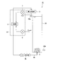
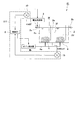
- FIG. 1 is a schematic diagram showing a water treatment system according to the first embodiment.
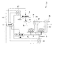
- FIG. 2 is a schematic diagram showing the water treatment system of the second embodiment.
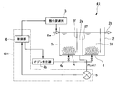
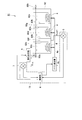
- FIG. 3 is a schematic diagram showing a water treatment system of the third embodiment.
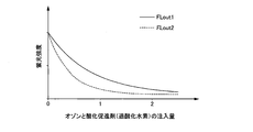
- FIG. 4 is a diagram showing a graph showing the relationship between the injection amounts of ozone and an oxidation promoter and the fluorescence intensity.
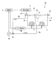
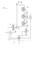
- FIG. 5 is a schematic diagram which shows the water treatment system of 4th Embodiment.
- FIG. 6 is a schematic diagram showing a water treatment system according to the fifth embodiment.
- FIG. 7 is a schematic diagram which shows the water treatment system of 6th Embodiment.
- FIG. 8 is a schematic diagram which shows the water treatment system of 7th Embodiment.
- FIG. 1 is a schematic diagram showing a water treatment system according to the first embodiment.
- FIG. 2 is a schematic diagram showing the water treatment system of the second embodiment.
- FIG. 3 is a schematic diagram showing a water treatment system of the third
- FIG. 9 is a schematic diagram which shows the water treatment system of 8th Embodiment.
- FIG. 10 is a schematic diagram which shows the water treatment system of 9th Embodiment.
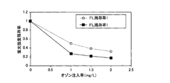
- FIG. 11 is a graph showing the relationship between the residual ratio of the fluorescence intensity and the ozone injection amount in the example.
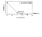
- FIG. 12 is a diagram showing a graph showing the relationship between the 2-MIB concentration and the ozone injection amount in the example.
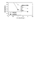
- FIG. 13 is a diagram showing a graph showing the relationship between the residual ratio of the fluorescence intensity and the ozone injection amount in the example.
- the water treatment system, control device, and water treatment method of the present embodiment may be applied to either treatment of tap water or sewage, but in the present embodiment, purification treatment of tap water at a water purification plant is taken as an example.
- the water treatment system 1 of the present embodiment injects an oxidation accelerator into the treatment tank 2 into which the water to be treated is introduced and the water to be treated before or after introduction into the treatment tank 2.
- the oxidation accelerator injecting section 3 and the ozone injecting section 4 installed in the treatment tank 2 for bringing ozone into contact with the water to be treated which has been injected with the oxidation accelerator flowing in the treatment tank 2, and after the start of ozone contact
- the treated water measuring section 5 for measuring the characteristic value of the treated water before the end of contact, and the amount of the oxidation accelerator injected by the oxidation accelerator injecting section 3 or the ozone injecting section 4 based on the measurement result of the treated water measuring section 5.
- a control unit 6 for controlling one or both of the ozone injection amounts according to.
- the water treatment system 1 is further provided with a raw water measuring unit 7 that measures the characteristic value of the water to be treated before being introduced into the treatment tank 2.
- the treated water measuring unit 5, the control unit 6, and the raw water measuring unit 7 constitute a control device 11 used in the water treatment system.
- each configuration will be described.
- the treatment tank 2 is a tank in which the water to be treated is introduced into the tank and ozone is brought into contact with the water to be treated passing through the tank.
- the treatment tank of the present embodiment is divided into two divided treatment tanks, and ozone is brought into contact with the water to be treated in each divided treatment tank.
- the treatment tank 2 is provided with an inflow part 2a into which the water to be treated flows and an outflow part 2b from which the water to be treated flows out.
- the processing tank 2 is provided with two divided processing tanks 2c and 2d.
- a connection channel 2e is provided between the two divided processing tanks 2c and 2d.
- the connection channel 2e is partitioned from the divided processing tanks 2c and 2d by the partition wall 2f.
- the water to be treated introduced into the treatment tank 2 from the inflow portion 2a flows out of the treatment tank 2 from the outflow portion 2b through the divided treatment tank 2c, the connection flow passage 2e and the divided treatment tank 2d.
- the oxidation accelerator reacts with ozone in the treated water to generate OH radicals, and the decomposition of the substance to be treated in the treated water by the OH radicals proceeds.
- the oxidation accelerator injection section 3 injects the oxidation accelerator into the water to be treated before or after introduction into the treatment tank 2.
- the oxidation accelerator injection unit 3 is configured to inject the oxidation accelerator into the water to be treated before being introduced into the treatment tank 2.
- the oxidation accelerator injection unit 3 is connected to the control unit 6, and the amount of the oxidation accelerator injected into the water to be treated is controlled by a command from the control unit 6.
- Examples of the oxidation promoter include hydrogen peroxide.
- the ozone injection unit 4 is installed in the processing tank 2.
- the ozone injection unit 4 is installed in each of the two divided processing tanks 2c and 2d.
- the ozone injecting section 4 may be, for example, an air diffuser, an air diffusing plate, or an injector as long as it can introduce a bubble-like gas into the water to be treated.
- the ozone injecting unit 4 is installed at the bottom of each of the divided treatment tanks 2c and 2d, and when the bubbles containing ozone injected from the ozone injecting unit 4 rise in the divided treatment tanks 2c and 2d, the ozone is injected into the water to be treated. It comes in contact.
- the ozone injecting unit 4 Since the ozone injecting unit 4 is installed in the two divided treatment tanks 2c and 2d, the water to be treated comes into contact with ozone in the divided treatment tank 2c, and then comes into contact with ozone in the divided treatment tank 2d. In this way, ozone comes into contact with the water to be treated twice in the treatment tank 2.
- the contact of ozone when the treated water first comes into contact with ozone in the divided treatment tank 2c, the contact of ozone is started, and when the treated water in the divided treatment tank 2d does not come into contact with ozone, the contact of ozone is finished. And
- the entire range in which the plurality of ozone injection parts 4 are installed is called an ozone contact area.
- the ozone contact area in the present embodiment is a range from a position where the water to be treated first comes into contact with ozone in the divided treatment tank 2c to a position where the treated water does not come into contact with ozone in the divided treatment tank 2d.
- the area between the ozone injection parts 4 is also included in the ozone contact area. That is, in the case of this embodiment, the connection channel 2e is also included in the ozone contact region.
- the position where the water to be treated comes into contact with ozone for the first time in the divided treatment tank 2c corresponds to the time when the contact of ozone is started, and the position where the treated water does not come into contact with ozone in the divided treatment tank 2d is the above ozone. Respond at the end of contact.
- the ozone injection unit 4 is connected to the ozone generator 4b via a pipe 4a.
- a fluid containing ozone generated in the ozone generator 4b is sent to the ozone injection unit 4 through the pipe 4a, and ozone is injected from the ozone injection unit 4 into the water to be treated.
- the ozone generator 4b is connected to the controller 6, and the amount of ozone injected into the water to be treated by the ozone injector 4 is controlled by a command from the controller 6.
- the treated water measuring unit 5 measures the characteristic value of the treated water.
- the treated water measuring unit 5 of the present embodiment is installed in the connection flow path 2e, and is configured to measure the characteristic value of the water to be treated flowing in the connection flow path 2e.
- the water to be treated flowing through the connection channel 2e is the water to be treated after the start of the ozone contact and before the end of the ozone contact, and the treated water measuring unit 5 measures the characteristic value of the water to be treated.
- the measured characteristic value is sent to the control unit 6.
- the treated water measuring unit 5 when the time required for the water to be treated to pass through the ozone contact region is T, the treated water measuring unit 5 is arranged at any position within the range of more than 0T and 0.6T. Is preferably provided.
- the treated water measurement part 5 is preferably arranged at any position within the range of 0.4T to 0.6T. ..
- the connection flow path 2e in which the treated water measuring unit 5 is installed is in the range of 0.4T to 0.6T.
- the time T is the time required from the start of ozone contact to the end of ozone contact.
- the treated water measuring unit 5 is installed at a position overlapping with the ozone injecting unit 4, bubbles containing ozone will interfere with the measurement of the characteristic value. Therefore, the treated water measuring unit 5 is installed at a position not overlapping the ozone injecting unit 4. Preferably.
- the treated water measuring unit 5 can measure the characteristic value of the water to be treated which is in contact with ozone.
- the characteristic value of the water to be treated which is in contact with ozone, rather than the characteristic value of the water to be treated after the end of contact with ozone, one of the injection amount of the oxidation accelerator or the ozone injection amount is measured, as described later. Alternatively, both can be controlled without excess or deficiency.
- the raw water measuring unit 7 is installed outside the treatment tank 2 and upstream of the inflow unit 2a, and measures the characteristic value of the treated water before being introduced into the treatment tank 2.
- the installation position of the raw water measurement unit 7 is upstream of the installation position of the oxidation promoter injection unit 3, and the characteristic value of the water to be treated before the injection of the oxidation promoter is measured.
- the characteristic value of the water to be treated after the injection of the oxidation accelerator is measured, the characteristic value may be influenced by the oxidation accelerator, which is not preferable.
- the measured characteristic value is sent to the control unit 6.
- the characteristic values measured by the treated water measuring unit 5 and the raw water measuring unit 7 of the present embodiment are determined by what kind of measuring means is specifically used as the treated water measuring unit 5 and the raw water measuring unit 7.
- the treated water measuring unit 5 and the raw water measuring unit 7 of this embodiment are fluorescence photometers. Therefore, the characteristic value sent to the control unit 6 is the fluorescence intensity.
- the fluorometer measures the fluorescence intensity by irradiating water to be measured with excitation light. In the water supply process, the fluorescence intensity corresponding to organic substances of natural origin (referred to as fulvic acid-like organic substances, etc.) is almost similar if the fluorescence intensity is 420 to 460 nm with respect to the excitation light 320 to 360 nm.
- the wavelength of the excitation light is set to 320 to 360 nm.
- the control unit 6 obtains the residual rate of the characteristic value (fluorescence intensity) based on the measurement results of the raw water measuring section 7 and the treated water measuring section 5, and when the residual rate deviates from the threshold value, the oxidation promoter injection section 3 promotes the oxidation. Either or both of the agent injection amount and the ozone injection amount by the ozone injection unit 4 are controlled. The operation of the controller 6 will be described in detail in the description of the water treatment method.
- the water treatment method of the present embodiment uses the water treatment system 1 shown in FIG. 1, injecting an oxidation accelerator into the water to be treated by the oxidation accelerator injecting section 3 and injecting the oxidation accelerator containing the oxidation accelerator in the ozone injecting section 4.
- An accelerated oxidation step of bringing ozone into contact with the treated water a treated water measurement step of measuring the characteristic value of the treated water from after the start of contact of ozone to before the end of contact of ozone, and the acceleration of oxidation by the oxidation promoter injecting section 3.
- the accelerated oxidation step, the treated water measurement step, and the control step may be performed in this order, and the treated water measurement step and the control step may be performed during the implementation of the accelerated oxidation step.
- a raw water measurement step of measuring the characteristic value of the water to be treated before introduction into the treatment tank 2 is performed in advance.
- the residual rate of the measurement result is obtained based on the measurement results of the raw water measurement step and the treated water measurement step, and when the residual rate deviates from the threshold value, the oxidation accelerator injection amount by the oxidation accelerator injection unit 3 or Either or both of the ozone injection amounts by the ozone injection unit 4 are controlled.
- the raw water measuring unit 7 measures the characteristic value of the water to be treated before it is introduced into the treatment tank 2.
- the raw water measuring unit 7 uses a fluorescence photometer, and the characteristic value is fluorescence intensity.
- the fluorescence intensity measured by the fluorometer is sent to the control unit 6.
- the water to be treated is, for example, water to be treated after turbid components have been removed from the sedimentation tank in a water purification plant.
- the oxidation accelerator is injected into the water to be treated from the oxidation accelerator injection portion 3.
- Hydrogen peroxide for example, is injected as an oxidation promoter.
- the water to be treated, into which the oxidation accelerator has been injected is introduced into the divided treatment tank 2c from the inflow portion 2a of the treatment tank 2.
- ozone is generated by the ozone generator 4b, and ozone is injected into the water to be treated in the divided treatment tank 2c from the ozone injecting section 4 through the pipe 4a.
- Gas containing ozone forms bubbles from the ozone injecting section 4 and contacts the water to be treated.
- the injected ozone reacts with the oxidation promoter to generate OH radicals, and the substance to be treated in the water to be treated is decomposed.
- the molar ratio of hydrogen peroxide to ozone is 1 to 5.
- the production risk of bromic acid which is a disinfection by-product of ozone
- the production risk of bromic acid can be reduced by increasing the ratio of hydrogen peroxide within the range of 1 to 5.
- the water to be treated that has been treated in the divided treatment tank 2c is sent from the divided treatment tank 2c to the connection channel 2e. Then, as the treated water measuring step, the characteristic value of the treated water is measured by the treated water measuring unit 5 installed in the connection flow path 2e.
- the treated water measurement unit 5 uses a fluorescence photometer, and the characteristic value is fluorescence intensity.
- the fluorescence intensity measured by the fluorometer is sent to the control unit 6.
- the water to be treated is sent from the connection channel 2e to the divided treatment tank 2d. Since the required amount of hydrogen peroxide has been added to the water to be treated in advance by the oxidation accelerator injecting section 3, hydrogen peroxide remains in the water to be treated sent to the divided treatment tank 2d in the subsequent stage. Is in a state. On the other hand, most of the ozone injected in the former division treatment tank 2c is decomposed by hydrogen peroxide, and when it is sent to the latter division treatment tank 2d, almost no dissolved ozone is contained. is there.
- ozone is injected from the ozone injection unit 4 into the water to be treated in the divided treatment tank 2d.
- the injected ozone reacts with the oxidation promoter to generate OH radicals, and the substance to be treated remaining in the water to be treated is decomposed.
- the fluorescence intensity measured in the raw water measurement step and the treated water measurement step is input to the control unit 6.
- the fluorescence intensity is approximately the same as the fluorescence intensity corresponding to an organic substance of natural origin (referred to as a fulvic acid-like organic substance, etc.) in the purification process of water supply, if the fluorescence is 420 to 460 nm with respect to the excitation light 320 to 360 nm, but is preferable. May measure the fluorescence (wavelength near 425 nm) intensity with respect to the excitation light (wavelength near 345 nm). This fluorescence intensity has a correlation with the representative index E260 (absorbance) of the concentration of organic substances, TOC, the ability to generate trihalomethane, and the like.
- the control unit 6 obtains the residual ratio of the fluorescence intensity based on the fluorescence intensity measured in the raw water measurement step and the treated water measurement step.
- the residual ratio of the fluorescence intensity is measured by the following formula.
- FLin is the fluorescence intensity measured in the raw water measurement step
- FLout1 is the fluorescence intensity measured in the treated water measurement step.
- the measured residual rate is less than a predetermined lower limit threshold value of the residual rate
- either one of the oxidation accelerator injection amount by the oxidation accelerator injection unit 3 and the ozone injection amount by the ozone injection unit 4 is determined. Or reduce both.
- either the injection amount of the oxidation accelerator injected by the oxidation accelerator injection unit 3 or the ozone injection amount of the ozone injection unit 4 is determined. Or increase both.
- the reason why the fluorescence intensity of the water to be treated during ozone injection is used to control the water treatment system will be explained.
- the substance to be treated is decomposed by the OH radicals generated by the added ozone and hydrogen peroxide, but since the naturally-occurring organic substances existing in the water are also decomposed at the same time, the value of the fluorescence intensity is small. Become.
- Fig. 4 shows the situation.
- the horizontal axis represents the injection amounts of ozone and hydrogen peroxide, and the vertical axis represents the fluorescence intensity.
- ozone is injected from the two ozone injecting units 4, and the injection amount of ozone in FIG. 4 means the total amount injected from these two ozone injecting units 4.
- FLout1 is the fluorescence intensity measured in the treated water measurement step.
- FLout2 is the fluorescence intensity of the water to be treated measured near the outflow portion 2b of the divided treatment tank 2d.
- Both FLout1 and FLout2 become smaller as the injection amount of ozone and hydrogen peroxide increases. Since FLout1 is the fluorescence intensity in the middle stage of the treatment with ozone and hydrogen peroxide, it is higher than the fluorescence intensity FLout2 at the end stage of the treatment with ozone and hydrogen peroxide. Further, the slope of the FLout2 curve becomes smaller after the horizontal axis exceeds "1", but the slope of the FLout1 curve becomes smaller as the FLout2 curve becomes larger even if the horizontal axis exceeds "1". Of course, the inclination finally becomes small when the value exceeds "2".
- the state of the accelerated oxidation treatment in the entire treatment tank 2 can be grasped from the residual rate (FLout2) in the vicinity of the outflow portion 2b of the divided treatment tank 2d, and in the case of removing the mold odor in the water treatment, the residual rate (FL residual rate).
- the ratio 2) should be maintained at about 0.1 to 0.2.
- the residual rate (FL residual rate 1) is used as the control index.
- the connection channel 2e is still in the middle of the reaction in the connection channel 2e, which is a range corresponding to 0.4T to 0.6T when T is the time required for the water to be treated to pass through the ozone contact region.
- the residual rate (FL residual rate 1) has not fallen sufficiently and is more appropriate than the residual rate (FL residual rate 2) as an index for controlling the addition amount of ozone and hydrogen peroxide.
- the residual rate of fluorescence intensity (FL residual rate 1) is obtained, and the residual rate (FL residual rate 1) is obtained. Is feedback-controlled so that the addition amount of ozone and hydrogen peroxide becomes a predetermined target value (target FL residual rate 1).
- the ratio of hydrogen peroxide added to ozone added may be between 1 and 5 in terms of molar ratio. Therefore, for example, in order to prevent excessive addition of hydrogen peroxide, the molar ratio is fixed at around 1 and the addition amounts of ozone and hydrogen peroxide are controlled.
- the production risk of bromic acid which is a disinfection by-product of ozone
- the production risk of bromic acid can be reduced by increasing the ratio of hydrogen peroxide within the range of 1 to 5.
- the ratio of the hydrogen peroxide may be increased, or if there is a mechanism for grasping the risk in real time by other water quality indicators or the like, a method of automatically changing the ratio of hydrogen peroxide in conjunction with it may be adopted.
- the treated water measuring unit 5 that measures the characteristic value of the treated water from after the ozone contact is started to before the ozone contact is ended.
- a control unit 6 for controlling either one or both of the oxidation accelerator injection amount by the oxidation accelerator injection unit 3 and the ozone injection amount by the ozone injection unit 4 based on the measurement result of the treated water measurement unit 5,
- the injection amount of the oxidation accelerator or the injection amount of ozone on the basis of the characteristic value of the water to be treated in the treatment tank 2 which is in contact with ozone, the change amount of the characteristic value with respect to the addition amounts of ozone and hydrogen peroxide can be controlled.
- the control can be performed in a large range, ozone and hydrogen peroxide can be injected in an appropriate amount range, and the characteristic value of the water to be treated can be reliably reduced while reducing the risk of bromic acid production.
- mold odor can be reduced and the risk of bromic acid production can be reduced in the process of purifying tap water.
- various environmental management values of the water to be treated can be reduced.
- the raw water measuring unit 7 for measuring the characteristic value of the treated water before being introduced into the treatment tank 2 is further provided, and the control unit 6 controls the raw water.
- the control unit 6 controls the raw water.
- the range in which the ozone injecting section 4 is arranged in the treatment tank 2 is defined as the ozone contact area, and the water to be treated is required for passing through the ozone contact area.
- the treated water measuring unit 5 is arranged at any position in the range of more than 0T and 0.6T, and more preferably in the range of 0.4T to 0.6T, whereby ozone and hydrogen peroxide can be obtained.
- the treatment tank 2 is provided with the plurality of divided treatment tanks 2c and 2d and the connection flow passage 2e, and ozone is injected into the divided treatment tanks 2c and 2d. Since the part 4 is provided and the treated water measuring part 5 is arranged in the connection flow path 2e, the treated water measuring part 5 measures the characteristic value of the treated water without being affected by bubbles containing ozone. It is possible to inject ozone and hydrogen peroxide in an appropriate amount range by controlling either or both of the injection amount of the oxidation accelerator and the injection amount of ozone.
- ozone once reduced by the injection of hydrogen peroxide can be reinjected by the ozone injecting unit 4 installed in the subsequent stage, so that decomposition of the substance to be treated can be further prevented. Can be promoted.
- the raw water measuring unit 7 and the treated water measuring unit 5 are fluorescence photometers, even a trace amount of the substance to be treated can be detected with high sensitivity. be able to. Further, since the fluorescence photometer can measure the fluorescence intensity without being affected by dissolved ozone or hydrogen peroxide, it is possible to control ozone and hydrogen peroxide within appropriate ranges.
- the water treatment method of the present embodiment when injecting an oxidation promoter into water to be treated and contacting ozone to decompose the substance to be treated, after the contact start of ozone to before the end of contact.
- the characteristic value of the treated water between the two is measured, and either or both of the injection amount of the oxidation promoter and the injection amount of ozone are controlled based on the measurement result. It is possible to control in a range where the amount of change is large, it is possible to inject ozone and hydrogen peroxide in an appropriate amount range, and it is possible to reliably reduce the characteristic value of the water to be treated while reducing the risk of bromic acid production. You can As a result, mold odor can be reduced and the risk of bromic acid production can be reduced in the process of purifying tap water. Also, in sewage treatment, various environmental management values of the water to be treated can be reduced.
- the residual rate of the characteristic value is obtained by further measuring the characteristic value of the water to be treated before being introduced into the treatment tank 2, and when the residual rate deviates from the threshold value,
- the oxidation promoter injection amount and the ozone injection amount it becomes possible to inject ozone and hydrogen peroxide within an appropriate range even when the characteristic value of the raw water changes. It is possible to reliably reduce the amount of the substance to be treated in the water to be treated while reducing the generation risk.
- control device 11 of the present embodiment can be attached to an existing treatment tank having an ozone injecting section, and by combining the control device 11 of the present embodiment with an existing treatment tank, the water treatment of the present embodiment can be performed.
- the system can be easily constructed.
- FIG. 2 shows a water treatment system 21 of this embodiment. Note that, of the constituent elements shown in FIG. 2, the same constituent elements as those shown in FIG. 1 are designated by the same reference numerals, and the description thereof will be omitted.
- the difference between the water treatment system 21 of this embodiment and the water treatment system 1 of the first embodiment lies in the configuration of the treatment tank.
- the processing tank 2 in which the connection channel 2e is provided between the divided processing tanks 2c and 2d is used, but the processing tank 22 of the present embodiment does not have the division processing tank and the connection channel.
- the structure of the processing tank will be mainly described.
- the treatment tank 22 of the present embodiment is a tank in which the water to be treated is introduced into the tank and ozone is brought into contact with the water to be treated passing through the tank.
- the treatment tank 22 is provided with an inflow part 2a into which the water to be treated flows and an outflow part 2b from which the water to be treated flows out.
- the water to be treated introduced into the treatment tank 22 from the inflow portion 2a passes through the treatment tank 22 and flows out from the outflow portion 2b.
- the treatment tank 22 of the present embodiment is a single treatment tank, and two ozone injecting units 4 are arranged in the treatment tank 22 along the flowing direction of the water to be treated, and the treatment water measuring unit 5 has two treatment units. It is arranged between two ozone injection parts 4.
- the oxidation accelerator reacts with ozone in the treated water to generate OH radicals, and the decomposition of the substance to be treated in the treated water by the OH radicals proceeds.
- the ozone injection unit 4 is installed in the processing tank 22.
- two ozone injection parts 4 are installed inside the processing tank 22.
- the two ozone injection parts 4 are arranged along the direction in which the water to be treated flows.
- the ozone injection unit 4 on the upstream side in the flow direction of the treated water may be referred to as a first ozone injection unit 4c
- the ozone injection unit 4 on the downstream side in the flow direction of the treated water may be referred to as a second ozone injection unit 4d. ..
- the first ozone injecting section 4c and the second ozone injecting section 4d are separated from each other along the flow direction of the water to be treated, and the treated water measuring section 5 is located between them.
- the first and second ozone injecting parts 4c and 4d are installed at the bottom of the processing tank 22, respectively, and bubbles containing ozone injected from the first and second ozone injecting parts 4c and 4d rise in the processing tank 22. When it does, it comes into contact with the water to be treated. Since the two ozone injection parts 4 are installed along the flow direction of the water to be treated, the water to be treated is brought into contact with the ozone injected from the first ozone injection part 4c, and then the second ozone injection part 4d.
- ozone is brought into contact with the water to be treated twice in the treatment tank 22.
- the contact of the ozone is started, and the water to be treated passes through the second ozone injecting unit 4d and becomes ozone in the water to be treated. The time when contact with ozone ends when contact with ozone ends.
- the entire range in which the plurality of ozone injection parts 4 are installed is called an ozone contact area.
- the water to be treated contacts the ozone to the water to be treated from the position where the water to be treated contacts the ozone for the first time by the first ozone injecting unit 4c and passes through the second ozone injecting unit 4d.
- the range is up to the missing position.
- the area between the ozone injection parts 4 is also included in the ozone contact area. That is, in the case of this embodiment, the location where the treated water measurement unit 5 is installed is also included in the ozone contact area.
- the position where the water to be treated comes into contact with ozone for the first time in the treatment tank 22 corresponds to the time when the contact with ozone is started, and the position where the water to be treated does not come into contact with ozone in the treatment tank 22 is the above ozone contact end. Sometimes respond.
- the first and second ozone injecting units 4c and 4d are connected to the ozone generator 4b through the pipe 4a.
- a fluid containing ozone generated in the ozone generator 4b is sent to the first and second ozone injecting units 4c and 4d via the pipe 4a, and ozone is supplied to the water to be treated from the first and second ozone injecting units 4c and 4d. Injected.
- the ozone generator 4b is connected to the controller 6, and the amount of ozone injected into the water to be treated is controlled by a command from the controller 6.
- the treated water measuring unit 5 measures the characteristic value of the treated water.
- the treated water measurement unit 5 of the present embodiment is installed between the first ozone injection unit 4c and the second ozone injection unit 4d.
- the treated water measurement unit 5 is configured to measure the characteristic value of the treated water passing between the first ozone injection unit 4c and the second ozone injection unit 4d.
- the water to be treated that flows between the first ozone injecting unit 4c and the second ozone injecting unit 4d is the water to be treated after the start of the ozone contact and before the end of the ozone contact, and the treated water measuring unit 5 uses this treated water.
- the characteristic value of water is measured.
- the measured characteristic value is sent to the control unit 6.
- the treated water measuring unit 5 when the time required for the water to be treated to pass through the ozone contact region is T, the treated water measuring unit 5 is arranged at any position within the range of more than 0T and 0.6T. Is preferably provided.
- the treated water measurement part 5 is preferably arranged at any position within the range of 0.4T to 0.6T. ..
- the treated water measuring unit 5 is installed at a position overlapping the first and second ozone injecting units 4c and 4d, bubbles containing ozone will obstruct the measurement of the characteristic value. It is preferable to install it at a position where it does not overlap with the injection parts 4c and 4d.
- the characteristic value of the treated water in contact with ozone can be measured.
- the characteristic value of the treated water that is in contact with ozone not the characteristic value of the treated water after the end of contact with ozone, one or both of the injection amount of the oxidation accelerator or the ozone injection amount is insufficient. It becomes possible to control without it.
- control unit 5 the raw water measuring unit 7, and the ozone generator 4b shown in FIG. 2 have the same configurations as those of the first embodiment shown in FIG. Further, in the present embodiment, similarly to the first embodiment, the control device 11 is configured by the treated water measurement unit 5, the control unit 6, and the raw water measurement unit 7.
- the water treatment method of this embodiment uses the water treatment system 21 shown in FIG. 2 and performs the accelerated oxidation step, the treated water measurement step, and the control step, as in the first embodiment. Further, in the water treatment method of the present embodiment, as in the first embodiment, the raw water measurement step of measuring the characteristic value of the water to be treated before introduction into the treatment tank 22 is performed.
- the water treatment method of the present embodiment may be performed in the order of the raw water measurement step, the accelerated oxidation step, the treated water measurement step, and the control step, and during the implementation of the accelerated oxidation step, the raw water measurement step, the treated water measurement step and the control step You may go.
- the raw water measuring unit 7 measures the characteristic value of the water to be treated before it is introduced into the treatment tank 22.
- the raw water measuring unit 7 uses a fluorescence photometer, and the characteristic value is fluorescence intensity.
- the fluorescence intensity measured by the fluorometer is sent to the control unit 6.
- the water to be treated into which the oxidation accelerator (for example, hydrogen peroxide) has been injected by the oxidation accelerator injection unit 3 is introduced into the treatment tank 22 from the inflow portion 2a of the treatment tank 22. Further, ozone is generated by the ozone generator 4b, and ozone is injected into the water to be treated in the treatment tank 22 from the first ozone injecting section 4c through the pipe 4a.
- the oxidation accelerator for example, hydrogen peroxide
- the characteristic value of the treated water is measured by the treated water measuring unit 5 as the treated water measuring step for the treated water after the ozone is injected by the first ozone injecting unit 4c.
- the treated water measurement unit 5 uses a fluorescence photometer, and the characteristic value is fluorescence intensity.
- the fluorescence intensity measured by the fluorometer is sent to the control unit 6.
- the second ozone injecting unit 4d injects ozone into the water to be treated. Hydrogen peroxide remains in the water to be treated before the ozone is injected by the second ozone injector 4d. Therefore, the ozone injected from the second ozone injector 4d and the remaining oxidation accelerator react with each other to generate OH radicals, and the substance to be treated remaining in the water to be treated is decomposed.
- the fluorescence intensity measured in the raw water measurement step and the treated water measurement step is input to the control unit 6, and the control unit 6 obtains the residual ratio of the fluorescence intensity. ..
- either one of the oxidation accelerator injection amount by the oxidation accelerator injection unit 3 or the ozone injection amount by the ozone injection unit 4 is determined. Or reduce both.
- either the injection amount of the oxidation accelerator injected by the oxidation accelerator injection unit 3 or the ozone injection amount of the ozone injection unit 4 is determined. Or increase both.
- the treatment tank 22 is provided with the two ozone injecting units 4c and 4d, and the treated water measuring unit 5 is arranged between the ozone injecting units 4c and 4d. Therefore, the characteristic value of the water to be treated in the process of contacting ozone in the treatment tank 22 can be measured, and thus, the control is performed in a range in which the amount of change of the characteristic value with respect to the addition amount of ozone and hydrogen peroxide is large. It is possible to inject ozone and hydrogen peroxide in an appropriate amount range. This makes it possible to reliably reduce the characteristic value of the water to be treated while reducing the risk of bromic acid production. In addition, in the process of purifying tap water, mold odor can be reduced and the risk of bromic acid production can be reduced. Also, in sewage treatment, various environmental management values of the water to be treated can be reduced.
- the treated water measuring unit 5 can measure the characteristic value of the treated water without being affected by bubbles containing ozone. It is possible to inject ozone and hydrogen peroxide in an appropriate amount range by controlling either or both of the injection amount of the oxidation accelerator and the injection amount of ozone. Further, since the two ozone injecting units 4 are provided, the ozone once reduced by the injecting hydrogen peroxide can be reinjected by the second ozone injecting unit 4d installed in the subsequent stage, and the ozone to be treated can be The decomposition can be accelerated.
- FIG. 3 shows a water treatment system 31 of this embodiment. Note that, of the constituent elements shown in FIG. 3, the same constituent elements as those shown in FIG. 1 are designated by the same reference numerals, and description thereof will be omitted.
- the treatment tank 2 in which the connection channel 2e is provided between the divided treatment tanks 2c and 2d is used and the water to be treated is moved in the horizontal direction in the treatment tank 2 has been described.
- the treatment tank 32 of the present embodiment the water to be treated is moved in the vertical direction and the ozone injection section is also one.
- the structure of the processing tank will be mainly described.
- the treatment tank 32 of the present embodiment is a single vertically long treatment tank. Like the first embodiment, the water to be treated is introduced into the tank and ozone is brought into contact with the water to be treated passing through the tank. It is a tank.
- the treatment tank 32 is provided with an inflow part 32a into which the water to be treated flows and an outflow part 32b from which the water to be treated flows out.
- the inflow part 32 a is located above the processing bath 32, and the outflow part 32 b is located below the processing bath 32.
- the water to be treated introduced into the treatment tank 32 from the inflow portion 32a passes through the treatment tank 32 from the upper side to the lower side, and flows out from the outflow portion 32b.
- one ozone injection part 4 is arranged at the bottom of the processing tank 32 of this embodiment. Further, the treated water measuring unit 5 is arranged at a position between the inflow portion 32a and the outflow portion 32b of the treatment tank 32.
- the ozone injection unit 4 is installed at the bottom of the processing tank 32.
- the ozone injecting section 4 is located further below the outflow section 32b, but the ozone injecting section 4 may be located above the outflow section 32b and may be at the same height.
- the ozone injection unit 4 of the present embodiment injects ozone into the water to be treated flowing from above the treatment tank 32 from below the treatment tank 32. As a result, when bubbles containing ozone rise while diffusing in the treatment tank 32, they come into contact with the water to be treated flowing from above to below the treatment tank 32.
- the first contact of the water to be treated with the ozone by the ozone injecting unit 4 is defined as the start of ozone contact
- the time of no contact of the treated water with ozone is defined as the end of ozone contact. Is configured to rise in the treatment tank from the bottom of the treatment tank 32, so that the time when the water to be treated flows into the treatment tank 32 is the start of ozone contact, and the time when the water to be treated flows out of the treatment tank 32. Is the end of ozone contact.
- the ozone contact region in the present embodiment is a range from a position where the water to be treated first comes into contact with ozone in the treatment tank 32 to a position where the treatment water does not come into contact with ozone in the treatment tank 32.
- the position in the treatment tank 32 where the water to be treated comes into contact with ozone for the first time corresponds to the above-mentioned ozone contact start time, and the position in the treatment tank 32 where the water to be treated does not come into contact with ozone corresponds to the above ozone contact end time. To do.
- the ozone injection unit 4 is connected to the ozone generator 4b via a pipe 4a.
- the fluid containing ozone generated in the ozone generator 4b is sent to the ozone injection unit 4 through the pipe 4a, and ozone is injected into the water to be treated.
- the ozone generator 4b is connected to the controller 6, and the amount of ozone injected into the water to be treated is controlled by a command from the controller 6.
- the treated water measurement unit 5 measures the characteristic value of the water to be treated, and the treated water measurement unit 5 of the present embodiment is installed between the inflow portion 32a and the outflow portion 32b of the treatment tank 32, Moreover, it is installed above the ozone injection unit 4. As a result, the treated water measuring unit 5 measures the characteristic value of the treated water that flows from the upper portion to the lower portion of the treatment tank 32 and is in contact with ozone.
- the water to be treated flowing from the inflow part 32a to the outflow part 32b is the water to be treated after the start of contact of ozone and before the end of contact, and the treated water measuring unit 5 measures the characteristic value of this treated water. ..
- the measured characteristic value is sent to the control unit 6.
- the treated water measurement unit 5 when the time required for the water to be treated to pass through the ozone contact region is T, the treated water measurement unit 5 is located at any position in the range of more than 0T and 0.6T. Is preferably arranged at any position within the range of 0.4T to 0.6T.
- the time T is the time required from the start of ozone contact to the end of ozone contact.
- the treated water measuring unit 5 If the treated water measuring unit 5 is installed in the vicinity of the ozone injecting unit 4, bubbles containing ozone will obstruct the measurement of the characteristic value. Therefore, the treated water measuring unit 5 should be installed at a position as far as possible from the ozone injecting unit 4. preferable.
- the characteristic value of the treated water in contact with ozone can be measured.
- the characteristic value of the treated water that is in contact with ozone not the characteristic value of the treated water after the end of contact with ozone, one or both of the injection amount of the oxidation accelerator or the ozone injection amount is insufficient. It becomes possible to control without it.
- control unit 5 the raw water measuring unit 7, and the ozone generator 4b shown in FIG. 2 have the same configurations as those of the first embodiment shown in FIG. Further, in the present embodiment, similarly to the first embodiment, the control device 11 is configured by the treated water measurement unit 5, the control unit 6, and the raw water measurement unit 7.
- the water treatment method of this embodiment uses the water treatment system 31 shown in FIG. 3, and performs the accelerated oxidation step, the treated water measurement step, and the control step, as in the first embodiment. Further, in the water treatment method of the present embodiment, the raw water measurement step of measuring the characteristic value of the water to be treated before introduction into the treatment tank 32 is performed as in the first embodiment.
- the water treatment method of the present embodiment may be performed in the order of the raw water measurement step, the accelerated oxidation step, the treated water measurement step, and the control step, and during the implementation of the accelerated oxidation step, the raw water measurement step, the treated water measurement step and the control step You may go.
- the raw water measuring unit 7 measures the characteristic value of the water to be treated before it is introduced into the treatment tank 32.
- the raw water measuring unit 7 uses a fluorescence photometer, and the characteristic value is fluorescence intensity.
- the fluorescence intensity measured by the fluorometer is sent to the control unit 6.
- the water to be treated in which the oxidation accelerator for example, hydrogen peroxide
- the oxidation accelerator injection unit 3 is introduced into the treatment tank 32 from the inflow unit 32a.
- ozone is generated by the ozone generator 4b, and ozone is injected into the water to be treated in the treatment tank 32 from the ozone injecting section 4 through the pipe 4a.
- the ozone injected from the ozone injection part 4 reacts with the oxidation accelerator to generate OH radicals, and the substance to be treated in the water to be treated is decomposed.
- the treated water measuring unit 5 measures the characteristic value of the treated water for the treated water during the ozone injection by the ozone injecting unit 4.
- the treated water measurement unit 5 uses a fluorescence photometer, and the characteristic value is fluorescence intensity.
- the fluorescence intensity measured by the fluorometer is sent to the control unit 6.
- the fluorescence intensity measured in the raw water measurement step and the treated water measurement step is input to the control unit 6, and the control unit 6 obtains the residual ratio of the fluorescence intensity. ..
- either one of the oxidation accelerator injection amount by the oxidation accelerator injection unit 3 or the ozone injection amount by the ozone injection unit 4 is determined. Or reduce both.
- either the injection amount of the oxidation accelerator injected by the oxidation accelerator injection unit 3 or the ozone injection amount of the ozone injection unit 4 is determined. Or increase both.
- the treatment tank 32 is of a vertical type, and ozone is injected from below the treatment tank 32 into the water to be treated flowing downward from above the treatment tank 32. While the ozone is contacting the entire water to be treated, the characteristic value of the water to be treated which is in contact with ozone is measured in the middle of the treatment tank 32, and the measured characteristic value is the ozone injection amount or the oxidation accelerator injection amount. Since it is used for the control of 1., only one ozone injection part 4 is required to be provided in the treatment tank 32, and the configuration of the water treatment system 31 can be simplified.
- FIG. 5 shows a water treatment system 41 of this embodiment. It should be noted that, of the constituent elements shown in FIG. 5, the same constituent elements as those shown in FIG. 1 are designated by the same reference numerals, and description thereof will be omitted.
- the difference between the water treatment system 41 of the present embodiment and the water treatment system 1 of the first embodiment is that the raw water measuring unit 7 is omitted in the present embodiment. Therefore, the control unit 6 controls one or both of the oxidation accelerator injection amount by the oxidation accelerator injection unit 3 and the ozone injection amount by the ozone injection unit 4 based on the measurement result of the treated water measurement unit 5. Further, in the present embodiment, the treated water measuring unit 5 and the control unit 6 constitute the control device 101.
- the present embodiment can be applied when the water quality fluctuation of the water to be treated is small.
- the fluorescence intensity (FLin) of the water to be treated before being introduced into the treatment tank 2 is not measured, but only the fluorescence intensity (FLout1) of the water to be treated that passes through the connection channel 2e. Is measured and this fluorescence intensity (FLout1) is used as a control index. This is because if the fluctuation of the fluorescence intensity (FLin) is small, the fluorescence intensity (FLout1) and the residual rate (FL residual rate 1) can be regarded as substantially the same.
- the configuration of the water treatment system 41 can be simplified.
- the configuration in which the raw water measuring unit 7 is omitted is not limited to the example shown in FIG. 5, and may be applied to the water treatment systems 21 and 31 in FIG. 2 or 3.
- FIG. 6 shows a water treatment system 51 of this embodiment. Note that, of the constituent elements shown in FIG. 6, the same constituent elements as those shown in FIG. 1 are designated by the same reference numerals, and description thereof will be omitted.
- the difference between the water treatment system 51 of the present embodiment and the water treatment system 1 of the first embodiment is that the configurations of the treated water measurement unit 5 and the raw water measurement unit 7 are changed in the present embodiment.
- the treated water measuring unit 5 and the raw water measuring unit 7 are configured, and a treated water collecting pipe 5a for collecting a part of the treated water to be measured, and the raw water.
- the water quality measuring unit 5d is connected to the intake pipe 5b.
- the treated water sorting pipe 5a has one end inserted into the connection channel 2e of the treatment tank 2 and the other end connected to the switching unit 5c. As a result, the treated water sorting pipe 5a sorts a portion of the treated water flowing through the connection channel 2e and sends it to the switching unit 5c.
- the raw water sorting pipe 5b has one end arranged upstream of the oxidation promoter injection unit 3 of the treatment tank 2 and the other end connected to the switching unit 5c. As a result, the raw water fractionation pipe 5b fractionates a portion of the water to be treated before the injection of the oxidation promoter and sends it to the switching unit 5c.
- the switching unit 5c is installed at a confluence of the treated water preparative pipe 5a and the raw water preparatory pipe 5b, and the treated water or the raw water preparatory pipette collected by the treated water preparatory pipe 5a is collected. Either one of the treated water separated by the pipe 5b is supplied to the water quality measuring unit 5d.
- the water quality measuring unit 5d measures the characteristic value of the water to be treated.
- the water quality measuring unit 5d is a fluorescence photometer, and the characteristic value is fluorescence intensity.
- the fluorescence intensity (FLin) of the treated water and the amount of the treated water flowing through the connection channel 2e are measured by one water quality measuring unit 5d.
- the fluorescence intensity (FLout1) of the treated water can be alternately measured automatically, and the fluorescence intensity of the non-measured one is regarded as constant during that time, and the residual rate (FL residual rate 1) is calculated.
- the addition amounts of ozone and hydrogen peroxide are controlled. This embodiment is also effective when the water quality variation of the water to be treated is not so large.
- the treated water measuring unit 5 and the raw water measuring unit 7 are configured by using the treated water sorting pipe 5a, the raw water sorting pipe 5b, the switching unit 5c, and the water quality measuring unit 5d. Therefore, the expensive and maintenance-requiring measuring devices can be integrated into one unit, and the configuration of the water treatment system 51 can be simplified.
- the present embodiment is not limited to the example shown in FIG. 6 and may be applied to the water treatment systems 21 and 31 shown in FIG. 2 or 3.
- the water quality measuring unit 5d may be an absorptiometer, and the characteristic value may be absorbance.
- FIG. 7 shows a water treatment system 61 of this embodiment. It should be noted that, of the constituent elements shown in FIG. 7, the same constituent elements as those shown in FIG. 1 are designated by the same reference numerals, and description thereof will be omitted.
- the difference between the water treatment system 61 of the present embodiment and the water treatment system 1 of the first embodiment is that in the present embodiment, the treated water measurement unit 15 and the raw water measurement unit 17 are absorptiometers, and the characteristic value is absorbance. There is a point.
- the measuring wavelength of the absorptiometer is 250 to 270 nm.
- the treated water measuring unit 15, the control unit 6, and the raw water measuring unit 17 constitute the control device 111.
- Absorbance is an index that correlates with fluorescence intensity. Compared with the fluorescence intensity, the absorbance has a small change in the value due to the addition of ozone/hydrogen peroxide, so that it can be applied when the change is sufficient to control the ozone addition amount. Since the absorbance also reacts with dissolved ozone, it was difficult to apply the control to the treatment of ozone alone, but in the present embodiment, the reaction of ozone and hydrogen peroxide reduces the dissolved ozone concentration to near zero. It can be applied to control of oxidation treatment.
- the control using the absorbance is the same as the control method described in the first embodiment.
- the characteristic value measured by the treated water measuring unit 15 is read as the absorbance (E260out1)
- the characteristic value measured by the raw water measuring unit 17 is read as the absorbance (E260in).
- the residual rate (FL residual rate 1) should be read as the residual rate (E residual rate 1).
- the present embodiment it becomes possible to control one or both of the injection amount of the oxidation accelerator and the injection amount of ozone without excess or deficiency.
- the present embodiment is not limited to the example shown in FIG. 7, and may be applied to the water treatment systems 21 and 31 shown in FIG. 2 or 3. Further, when the quality of the treated water to be raw water is stable, the raw water measuring unit 17 may be omitted as shown in FIG. Further, the water quality measuring unit 5d in FIG. 6 may be replaced with an absorptiometer.
- FIG. 8 shows a water treatment system 71 of this embodiment. It should be noted that, of the constituent elements shown in FIG. 8, the same constituent elements as those shown in FIG. 1 are designated by the same reference numerals, and description thereof will be omitted.
- the difference between the water treatment system 71 of the present embodiment and the water treatment system 1 of the first embodiment is that in the present embodiment, the treated water measuring unit and the raw water measuring unit are respectively the total organic carbon measuring instrument 25 for treated water and The total organic carbon measuring instrument 27 for raw water is used.
- the total organic carbon measuring instrument 25 for treated water is arranged near the outflow portion 2b of the treatment tank 2 in order to measure the total organic carbon amount of the treated water after the end of contact with ozone.
- the treated water measuring unit 25, the control unit 6, and the raw water measuring unit 27 constitute the control device 121.
- the total organic carbon meter is a meter that measures the total organic carbon concentration (TOC) in water, and the TOC does not change because the organic substances in the water are not decomposed into water and carbon dioxide when ozone is treated alone.
- TOC is partially reduced by accelerated oxidation treatment. Therefore, the amount of ozone and hydrogen peroxide added can be controlled using TOC as a control index. Even if the total organic carbon measuring instrument is used, the TOC does not decrease significantly.
- the present embodiment it becomes possible to control one or both of the injection amount of the oxidation accelerator and the injection amount of ozone without excess or deficiency.
- the present embodiment is not limited to the example shown in FIG. 8 and may be applied to the water treatment systems 21 and 31 shown in FIG. 2 or 3.
- the total organic carbon measuring instrument 27 for raw water may be omitted as shown in FIG.
- the water quality measuring unit 5d in FIG. 6 may be replaced with a total organic carbon measuring instrument.
- FIG. 9 shows a water treatment system 81 of this embodiment. Note that, of the constituent elements shown in FIG. 9, the same constituent elements as those shown in FIG. 1 are designated by the same reference numerals, and description thereof will be omitted.
- the difference between the water treatment system 81 of the present embodiment and the water treatment system 1 of the first embodiment is that, in the present embodiment, three divided treatment tanks are provided in the treatment tank, and these three divided treatment water tanks are connected. Two connection channels are provided, and the treated water measuring unit is installed in the upstream connection water tank of the two connection channels.
- the treatment tank 82 of the present embodiment is provided with an inflow part 82a into which the water to be treated flows and an outflow part 82b from which the water to be treated flows out.
- the processing tank 82 is provided with three divided processing tanks 82c, 82d, and 82e.
- Connection channels 82f, 82g are provided between the three divided processing tanks 82c, 82d, 82e.
- the connection flow paths 82f and 82g are partitioned from the divided processing tanks 82c, 82d, and 82e by partition walls 82h, respectively.
- the water to be treated introduced into the treatment tank 82 from the inflow portion 82a passes through the divided treatment tank 82c, the connection flow passage 82f, the divided treatment tank 82d, the connection flow passage 82g, and the divided treatment tank 82e, and from the outflow portion 82b to the treatment tank 2 Is leaked to the outside.
- the ozone injection unit 4 is installed in each of the three divided processing tanks 82c, 82d, and 82e. Since the ozone injecting unit 4 is installed in each of the divided treatment tanks 82c, 82d, and 82e, the water to be treated comes into contact with ozone in the divided treatment tank 82c, and then with ozone in the divided treatment tank 82d, and further divided treatment. Contact with ozone in tank 82e. In this way, ozone comes into contact with the water to be treated three times in the treatment tank 2.
- the ozone contact region in the present embodiment is a range from a position where the water to be treated first comes into contact with ozone in the divided treatment tank 82c to a position where the treated water does not come into contact with ozone in the divided treatment tank 82e.
- the area between the ozone injection parts 4 is also included in the ozone contact area. That is, in the case of this embodiment, the connection channels 82f and 82g are also included in the ozone contact region.
- the position where the water to be treated comes into contact with ozone for the first time in the divided treatment tank 82c corresponds to the time when the contact of ozone is started, and the position where the treated water does not come into contact with ozone in the divided treatment tank 82e is the above ozone. Respond at the end of contact.
- the treated water measuring unit 5 of the present embodiment is installed in the upstream connection flow path 82f, and is configured to measure the characteristic value of the treated water flowing through the connection flow path 82f.
- the water to be treated flowing through the connection channel 82f is the water to be treated after the start of contact with ozone and before the end of contact, and the treated water measuring unit 5 measures the characteristic value of this treated water.
- the measured characteristic value is sent to the control unit 6.
- the treated water measuring unit 5 when the time required for the water to be treated to pass through the ozone contact region is T, the treated water measuring unit 5 is arranged at any position within the range of more than 0T and 0.6T. Is preferably provided.
- the treated water measurement part 5 is preferably arranged at any position within the range of 0.2T to 0.4T. ..
- the connection flow path 82f in which the treated water measuring unit 5 is installed is in the range of 0.2T to 0.3T.
- the time T is the time required from the start of ozone contact to the end of ozone contact.
- the treated water measuring unit 5 can measure the characteristic value of the water to be treated which is in contact with ozone.
- the characteristic value of the water to be treated which is in contact with ozone, rather than the characteristic value of the water to be treated after the end of contact with ozone, one of the injection amount of the oxidation accelerator or the ozone injection amount is measured, as described later. Alternatively, both can be controlled without excess or deficiency.
- the water treatment method is carried out in the same manner as in the first embodiment, using the water treatment system 81 described above.
- the treatment tank 82 is provided with three ozone injecting units, ozone once reduced by injecting hydrogen peroxide can be reinjected by the ozone injecting unit 4 installed in the subsequent stage. The decomposition of the target substance can be further promoted.
- FIG. 10 shows a water treatment system 91 of this embodiment. Note that, of the constituent elements shown in FIG. 10, the same constituent elements as those shown in FIG. 2 are designated by the same reference numerals, and description thereof will be omitted.
- the difference between the water treatment system 91 of the present embodiment and the water treatment system 21 of the second embodiment is that in the present embodiment, three ozone injecting parts are provided in the treatment tank, and among these three ozone injecting parts. This is the point where a treated water measurement unit was installed between the two ozone injection units on the upstream side.
- three ozone injecting parts 4 are installed inside the processing tank 92.
- the three ozone injecting parts 4 are arranged along the flowing direction of the water to be treated.
- these ozone injecting sections 4 may be referred to as a first ozone injecting section 94c, a second ozone injecting section 94d, and a third ozone injecting section 94e in order from the upstream side in the flow direction of the water to be treated.
- the first ozone injection unit 94c, the second ozone injection unit 94d, and the third ozone injection unit 94e are separated from each other along the flow direction of the water to be treated, and the first ozone injection unit 94c and the second ozone injection unit 94d are separated from each other.
- the treated water measuring unit 5 is located between them. Since the three ozone injection parts 4 are installed along the flow direction of the water to be treated, the water to be treated is brought into contact with the ozone injected from the first ozone injection part 94c, and then the second ozone injection part 94d. Is contacted with ozone injected from the third ozone injector and finally contacted with ozone injected from the third ozone injector 94e.
- ozone is brought into contact with the water to be treated three times in the treatment tank 92.
- the contact of the ozone is started, and the water to be treated passes through the third ozone injecting unit 94e and becomes ozone in the water to be treated.
- the entire range in which the plurality of ozone injection parts 4 are installed is called an ozone contact area.
- the water to be treated passes through the third ozone injecting portion 94e and comes into contact with ozone from the position where the water to be treated first comes into contact with ozone by the first ozone injecting portion 94c.
- the range is up to the missing position.
- the area between the ozone injection parts 4 is also included in the ozone contact area. That is, in the case of this embodiment, the location where the treated water measurement unit 5 is installed is also included in the ozone contact area.
- the position where the water to be treated comes into contact with ozone for the first time in the treatment tank 92 corresponds to the time when the contact with ozone is started, and the position where the water to be treated does not come into contact with ozone in the treatment tank 92 is the ozone contact end described above. Sometimes respond.
- the treated water measurement unit 5 of the present embodiment is installed between the first ozone injection unit 94c and the second ozone injection unit 94d.
- the treated water measurement unit 5 is configured to measure the characteristic value of the treated water passing between the first ozone injection unit 94c and the second ozone injection unit 94d.
- the water to be treated flowing between the first ozone injecting part 94c and the second ozone injecting part 94d is the water to be treated after the start of contact of ozone and before the end of contact of ozone, and the treated water measuring part 5 is the treated water.
- the characteristic value of water is measured.
- the measured characteristic value is sent to the control unit 6.
- the treated water measuring unit 5 when the time required for the water to be treated to pass through the ozone contact region is T, the treated water measuring unit 5 is arranged at any position within the range of more than 0T and 0.6T. Is preferably provided.
- the treated water measurement part 5 is preferably arranged at any position within the range of 0.2T to 0.4T. ..
- the characteristic value of the treated water in contact with ozone can be measured.
- the characteristic value of the treated water that is in contact with ozone not the characteristic value of the treated water after the end of contact with ozone, one or both of the injection amount of the oxidation accelerator or the ozone injection amount is insufficient. It becomes possible to control without it.
- the water treatment system 91 described above is used to carry out the water treatment method in the same manner as in the first embodiment.
- the treatment tank 92 is provided with three ozone injecting units, ozone once reduced by injecting hydrogen peroxide can be reinjected by the ozone injecting unit 4 installed in the subsequent stage. The decomposition of the target substance can be further promoted.
- 2-MIB (2-Methylisoborneol) was added to the water to be treated before introducing the treatment tank at a concentration of 50 ng/L. Then, the residual ratio of the fluorescence intensity with respect to the ozone injection ratio was examined. Hydrogen peroxide was used as an oxidation promoter, and the molar ratio of hydrogen peroxide to ozone was fixed at 1.0.
- FIG. 11 shows the residual ratio of the fluorescence intensity with respect to the ozone injection ratio.
- the residual rate (FL residual rate 1) is the ratio (FLout1/FLin) of the fluorescence intensity (FLout1) in the connection channel 2e to the fluorescence intensity (FLin) of the water to be treated before introduction into the treatment tank
- the residual rate (FL residual rate 1) is the ratio of the fluorescence intensity (FLout2) of the water to be treated measured near the outflow portion 2b of the divided treatment tank 2d to the fluorescence intensity (FLin) of the water to be treated before introduction into the treatment tank ( FLout1/FLin).
- the residual ratio of the fluorescence intensity as the control index of the ozone injection rate in the control unit is the ratio of the fluorescence intensity (FLout1) in the connection flow path 2e to the fluorescence intensity (FLin) of the water to be treated before introducing the treatment tank ( It is understood that it is preferable to use FLout1/FLin).
- FIG. 12 shows the relationship between the ozone injection rate and the concentration of 2-MIB in the water to be treated measured near the outflow portion 2b of the divided treatment tank 2d. It is understood that when the upper limit of 2-MIB emission from the treatment tank is 5 ng/L, the ozone injection amount should be 1.4 mg/L or more.
- FIG. 13 shows a graph in which the vertical axis of FIG. 1 is enlarged.
- the slope of the residual rate (FL residual rate 1) is 0.024
- the slope of the residual rate (FL residual rate 2) is 0.010
- the residual rate of the fluorescence intensity as the control index of the ozone injection rate in the control unit is the fluorescence intensity (FLout1) in the connection flow path 2e with respect to the fluorescence intensity (FLin) of the water to be treated before introducing the treatment tank. It is understood that it is preferable to use the ratio (FLout1/FLin).
- the treated water measuring unit for measuring the characteristic value of the treated water after the contact start of ozone before the contact end of ozone, based on the measurement results of the treated water measuring unit
- a control unit that controls either or both of the injection amount of the oxidation accelerator injected by the oxidation accelerator injection unit and the injection amount of the ozone by the ozone injection unit, both ozone and the oxidation in the accelerated oxidation treatment by the ozone and the oxidation accelerator are performed. Even if the dissolved ozone becomes almost zero because ozone is consumed by the reaction of the accelerator, the area for the accelerated oxidation treatment using OH radicals is sufficiently secured, and proper ozone addition and oxidation accelerator addition are sufficient. It is possible to provide a water treatment system, a control device, and a water treatment method capable of stably carrying out the above.
Landscapes
- Life Sciences & Earth Sciences (AREA)
- Hydrology & Water Resources (AREA)
- Engineering & Computer Science (AREA)
- Environmental & Geological Engineering (AREA)
- Water Supply & Treatment (AREA)
- Chemical & Material Sciences (AREA)
- Organic Chemistry (AREA)
- Treatment Of Water By Oxidation Or Reduction (AREA)
Abstract
オゾンと酸化促進剤による促進酸化処理において、オゾンと酸化促進剤の反応でオゾンが消費されるため溶存オゾンがほぼゼロとなる状況でも、OHラジカルを用いた促進酸化処理の領域を十分に確保し、過不足ない適切なオゾン添加、及び酸化促進剤添加を安定して実施できる水処理システム、制御装置及び水処理方法を提供する。 実施形態の制御装置は、処理槽と、酸化促進剤注入部と、オゾン注入部と、を備えた水処理システムで利用される制御装置であって、処理水測定部と、制御部とを持つ。処理水測定部は、オゾンの接触開始時後から接触終了時前の間の被処理水の特性値を測定する。制御部は、処理水測定部の測定結果に基づき酸化促進剤注入部による酸化促進剤注入量またはオゾン注入部によるオゾン注入量のいずれか一方または両方を制御する。
Description
本発明の実施形態は、水処理システム、制御装置及び水処理方法に関する。
従来、上水、下水、産業排水、プールなどの分野で、水中の有機物の酸化分解、殺菌、脱臭等の処理のためにオゾンが用いられている。しかしながら、オゾンによる酸化でも、親水化、低分子化はできても無機化することはできない。また、ダイオキシンや1,4-ジオキサン等の難分解性有機物は分解できない。
したがって、上述のような難分解性有機物を分解するに際しては、オゾンよりも酸化力の強いOHラジカルを用い、酸化分解することが有効な手段の一つである。OHラジカルの生成には、オゾン含有水に紫外線を照射する方法、過酸化水素のような酸化促進剤含有水にオゾンを添加する方法、酸化促進剤含有水に紫外線を照射する方法、過酸化水素のような酸化促進剤、オゾン、紫外線全て併用する方法、が水処理において一般的に用いられている。
このうち、オゾンと酸化促進剤を用いる方法は、上水向けオゾン処理などで副生成物である臭素酸イオンの生成抑制に効果がある方法として注目されている。例えば、現在、オゾンを利用した高度浄水処理は、カビ臭対策やトリハロメタン対策として国内外で採用されている処理方法であるが、オゾン添加によりオゾン処理の消毒副生成物である臭素酸イオンが生成してしまう。原水水質や水温などの影響によりオゾン処理による臭素酸生成リスクが高い場合、臭素酸生成量を抑えるにはオゾン添加量を抑える方法が現実的な方法として採用されている。しかし、原水中の処理対象物質の濃度が高い場合や、臭素酸生成リスクが高い場合には、臭素酸生成量を抑えつつ処理対象物質を目標以下まで処理することができない。一方、オゾンと酸化促進剤を併用する方法では、酸化促進剤を添加することで酸化力の強いOHラジカルが生成し、それを利用した促進酸化処理により処理対象であるカビ臭物質などの分解率を高め、同時に過酸化水素による臭素酸の還元作用により、臭素酸生成リスクを抑えられる。
このオゾンと酸化促進剤を用いる促進酸化処理では、オゾンと酸化促進剤を適切な添加量に維持することが重要となる。添加不足の場合、OHラジカルの生成量が不足し処理対象物質の分解が不十分となり、過剰の場合、オゾン発生電力、または薬品(過酸化水素)代などのランニングコストが増加し、両者のバランスが悪い場合、処理対象物質の分解が不十分となったり、特にオゾンが多いと臭素酸生成量が多くなってしまうという問題もある。
これに対し、オゾン添加後の溶存オゾン濃度を指標としてオゾン、または酸化促進剤を添加する方法が提案されている。過酸化水素のような酸化促進剤を併用しない従来のオゾン処理では(以下、単に“オゾン処理”とする)、オゾンが被処理水中に添加されると水中に溶け込み溶存オゾンとなり、水中の処理対象物質と反応する。オゾン添加量を多くすると処理対象物質との反応に使われなかったオゾンは水中の溶存オゾンとなる。被処理水中の溶存オゾン濃度がある一定値以上になるようオゾンを添加することで、処理対象物質の分解をある程度進めることができると見做し、オゾン添加後の水中の溶存オゾン濃度が一定となるようにオゾン添加量を制御する方法が用いられている。
従来、オゾンと過酸化水素による促進酸化において、溶存オゾン濃度を指標としてオゾン添加量を制御する方法がある。この方法では、過酸化水素を添加するとオゾンと過酸化水素の反応によりOHラジカルが生成し、そのOHラジカルが処理対象物質と反応するが、オゾンと過酸化水素の反応でオゾンが消費されるため溶存オゾンはほぼゼロとなる。つまり、溶存オゾンを指標とするには、オゾンが過剰添加になる場合がある。
また、連続通水処理プロセスにおいて、オゾン処理のみの領域を前半に設け、その被処理水の溶存オゾン濃度が一定となるように、全体のオゾン添加量と過酸化水素添加量を制御する方法が提案されている。この場合、前段のオゾン処理では過酸化水素が添加されていないため、過酸化水素の存在による溶存オゾンの消費はなく、オゾン処理としてオゾン添加量をコントロールできる。しかし、促進酸化処理の領域が後半のみとなることから処理対象物質の分解が十分に進まない場合がある。
また、蛍光強度を指標とすることでオゾンと過酸化水素などの酸化促進剤の添加量を適切に制御する方法が提案されている。オゾンの添加量に対する被処理水の蛍光強度の減少は、徐々に緩やかになることから、被処理水の蛍光強度を指標としてオゾンと過酸化水素の添加量を調節してもその変化を見落とす場合がある。
本発明が解決しようとする課題は、オゾンと酸化促進剤による促進酸化処理において、オゾンと酸化促進剤の反応でオゾンが消費されるため溶存オゾンがほぼゼロとなる状況でも、OHラジカルを用いた促進酸化処理の領域を十分に確保し、過不足ない適切なオゾン添加、及び酸化促進剤添加を安定して実施できる水処理システム、制御装置及び水処理方法を提供することである。
実施形態の制御装置は、処理槽と、酸化促進剤注入部と、オゾン注入部と、を備えた水処理システムで利用される制御装置であって、処理水測定部と、制御部とを持つ。
処理槽は、被処理水が導入される。
酸化促進剤注入部は、処理槽への導入前または導入後の被処理水に酸化促進剤を注入する。
オゾン注入部は、処理槽を流れる被処理水にオゾンを接触させる。
処理水測定部は、オゾンの接触開始時後から接触終了時前の間の被処理水の特性値を測定する。
制御部は、処理水測定部の測定結果に基づき酸化促進剤注入部による酸化促進剤注入量またはオゾン注入部によるオゾン注入量のいずれか一方または両方を制御する。
処理槽は、被処理水が導入される。
酸化促進剤注入部は、処理槽への導入前または導入後の被処理水に酸化促進剤を注入する。
オゾン注入部は、処理槽を流れる被処理水にオゾンを接触させる。
処理水測定部は、オゾンの接触開始時後から接触終了時前の間の被処理水の特性値を測定する。
制御部は、処理水測定部の測定結果に基づき酸化促進剤注入部による酸化促進剤注入量またはオゾン注入部によるオゾン注入量のいずれか一方または両方を制御する。
(第1の実施形態)
以下、第1の実施形態の水処理システム、制御装置及び水処理方法を、図面を参照して説明する。
以下、第1の実施形態の水処理システム、制御装置及び水処理方法を、図面を参照して説明する。
本実施形態の水処理システム、制御装置及び水処理方法は、上水、下水のいずれの処理に適用してもよいが、本実施形態では、浄水場における上水の浄化処理を例とする。
図1に示すように、本実施形態の水処理システム1は、被処理水が導入される処理槽2と、処理槽2への導入前または導入後の被処理水に酸化促進剤を注入する酸化促進剤注入部3と、処理槽2内に設置され、処理槽2内を流れる酸化促進剤を注入済みの被処理水にオゾンを接触させるオゾン注入部4と、オゾンの接触開始時後から接触終了時前の間の被処理水の特性値を測定する処理水測定部5と、処理水測定部5の測定結果に基づき酸化促進剤注入部3による酸化促進剤注入量またはオゾン注入部4によるオゾン注入量のいずれか一方または両方を制御する制御部6と、が備えられている。
また、水処理システム1には、処理槽2への導入前の被処理水の特性値を測定する原水測定部7が更に備えられている。
また、上記の処理水測定部5と、上記の制御部6と、上記の原水測定部7とによって、水処理システムで利用される制御装置11が構成されている。
以下、各構成について説明する。
以下、各構成について説明する。
処理槽2は、槽内に被処理水が導入され、槽内を通過する被処理水にオゾンを接触させる槽である。本実施形態の処理槽は、2つの分割処理槽に分けられており、各分割処理槽において被処理水にオゾンを接触させるように構成されている。
より具体的に、処理槽2には、被処理水が流入する流入部2aと、被処理水が流出する流出部2bとが設けられている。また、処理槽2は、2つの分割処理槽2c、2dが設けられている。2つの分割処理槽2c、2dの間には接続流路2eが設けられている。接続流路2eは、隔壁2fによって分割処理槽2c、2dから区画されている。流入部2aから処理槽2に導入された被処理水は、分割処理槽2c、接続流路2e及び分割処理槽2dを経て、流出部2bから処理槽2の外部に流出される。
処理槽2では、被処理水中において酸化促進剤とオゾンとが反応してOHラジカルが生成し、OHラジカルによる被処理水中の処理対象物質の分解が進む。
酸化促進剤注入部3は、処理槽2への導入前または導入後の被処理水に酸化促進剤を注入するものである。図1では、酸化促進剤注入部3が処理槽2に導入前の被処理水に酸化促進剤を注入する構成とされている。酸化促進剤注入部3は制御部6に接続されており、制御部6の指令によって被処理水への酸化促進剤の注入量が制御される。酸化促進剤としては、例えば過酸化水素が例示される。
オゾン注入部4は、処理槽2内に設置されている。本実施形態では、図1に示すように、2つの分割処理槽2c、2dのそれぞれに、オゾン注入部4が設置されている。オゾン注入部4は例えば、散気管、散気板またはインジェクターのような、気泡状の気体を被処理水中に導入可能なものであればよい。オゾン注入部4は各分割処理槽2c、2dの底部に設置されており、オゾン注入部4から注入されたオゾンを含む気泡が各分割処理槽2c、2d内を上昇する際に被処理水に接触するようになっている。オゾン注入部4が2つの分割処理槽2c、2dに設置されているため、被処理水は、分割処理槽2cにおいてオゾンと接触し、次いで、分割処理槽2dにおいてオゾンと接触する。このように、処理槽2内では2度に渡って被処理水にオゾンが接触する。本実施形態では、分割処理槽2cにおいて被処理水がはじめてオゾンに接触したときをオゾンの接触開始時とし、分割処理槽2dにおいて被処理水にオゾンに接触しなくなったときをオゾンの接触終了時とする。
また、本実施形態では、複数のオゾン注入部4が設置された全範囲をオゾン接触領域と呼ぶ。本実施形態におけるオゾン接触領域は、分割処理槽2cにおいて被処理水がはじめてオゾンに接触する位置から、分割処理槽2dにおいて被処理水にオゾンに接触しなくなった位置までの範囲とする。オゾン注入部4同士の間の領域もオゾン接触領域に含まれる。すなわち、本実施形態の場合は接続流路2eもオゾン接触領域に含まれる。
また、分割処理槽2cにおいて被処理水がはじめてオゾンに接触する位置は、上記のオゾンの接触開始時に対応し、分割処理槽2dにおいて被処理水にオゾンに接触しなくなった位置は、上記のオゾン接触終了時に対応する。
オゾン注入部4は、配管4aを介してオゾン発生器4bに接続されている。オゾン発生器4bにおいて生成したオゾンを含む流体が配管4aを介してオゾン注入部4に送られ、オゾン注入部4から被処理水にオゾンが注入される。オゾン発生器4bは制御部6に接続されており、制御部6の指令によって、オゾン注入部4による被処理水へのオゾンの注入量が制御される。
処理水測定部5は、被処理水の特性値を測定するものである。本実施形態の処理水測定部5は接続流路2eに設置されており、接続流路2eを流れる被処理水の特性値を測定するように構成されている。接続流路2eを流れる被処理水は、オゾンの接触開始時後から接触終了時前の被処理水であり、処理水測定部5はこの被処理水の特性値を測定する。測定された特性値は、制御部6に送られる。
本実施形態の水処理システム1では、被処理水がオゾン接触領域の通過に要する時間をTとしたときに、処理水測定部5は、0T超0.6Tの範囲の何れかの位置に配置されていることが好ましい。本実施形態のように、オゾン注入部4が2つ備えられている場合は、処理水測定部5は、0.4T~0.6Tの範囲の何れかの位置に配置されていることが好ましい。図1において処理水測定部5が設置される接続流路2eは、0.4T~0.6Tの範囲内にある。時間Tは、上述のオゾン接触開始時から、オゾン接触終了時までの所要時間とする。
ただし、処理水測定部5をオゾン注入部4と重なる位置に設置すると、オゾンを含む気泡が特性値測定の障害になるため、処理水測定部5はオゾン注入部4と重ならない位置に設置することが好ましい。
処理水測定部5を上述の位置に設置することで、処理水測定部5によってオゾンに接触中の被処理水の特性値を測定できる。オゾンの接触終了時後の被処理水の特性値ではなく、オゾンに接触中の被処理水の特性値を測定することで、後述するように、酸化促進剤の注入量またはオゾン注入量の一方または両方を過不足無く制御することができるようになる。
原水測定部7は、処理槽2の外部であって流入部2aよりも上流側に設置されており、処理槽2に導入前の被処理水の特性値を測定する。原水測定部7の設置位置は酸化促進剤注入部3の設置位置よりも上流側とし、酸化促進剤の注入前の被処理水の特性値を測定する。酸化促進剤の注入後の被処理水の特性値を測定すると、その特性値が酸化促進剤の影響を受けているおそれがあるので好ましくない。測定された特性値は、制御部6に送られる。
本実施形態の処理水測定部5及び原水測定部7によって計測される特性値は、処理水測定部5及び原水測定部7として具体的にどのような測定手段を用いるかによって定まる。本実施形態の処理水測定部5及び原水測定部7は、蛍光光度計である。そのため、制御部6に送る特性値は蛍光強度となる。蛍光光度計は、測定対象の水に励起光を照射して蛍光強度を測定する。水道プロセスでは自然由来の有機物(フルボ酸様有機物などと言う)に相当する蛍光強度として、励起光320~360nmに対する蛍光420~460nmであれば概ね近い値を示すが、好ましくは、励起光(波長345nm付近)に対する蛍光(波長425nm付近)強度を測定するのがよい。この蛍光強度は、有機物濃度の代表指標E260(吸光度)、TOC、トリハロメタン生成能などと相関がある。よって本実施形態では、励起光の波長を320~360nmとする。
制御部6は、原水測定部7及び処理水測定部5の測定結果に基づき特性値(蛍光強度)の残存率を求め、残存率が閾値から外れた場合に酸化促進剤注入部3による酸化促進剤注入量またはオゾン注入部4によるオゾン注入量のいずれか一方または両方を制御する。制御部6の動作は水処理方法の説明において詳細に述べる。
次に、本実施形態の水処理方法を説明する。本実施形態の水処理方法は、図1に示す水処理システム1を用い、酸化促進剤注入部3によって被処理水に酸化促進剤を注入するとともに、オゾン注入部4によって酸化促進剤を含む被処理水にオゾンを接触させる促進酸化ステップと、オゾンの接触開始時後から接触終了時前の間の被処理水の特性値を測定する処理水測定ステップと、酸化促進剤注入部3による酸化促進剤注入量またはオゾン注入部4によるオゾン注入量のいずれか一方または両方を制御する制御ステップと、を行う。本実施形態の水処理方法は、促進酸化ステップ、処理水測定ステップ、制御ステップの順に行ってもよく、促進酸化ステップの実施中に、処理水測定ステップ及び制御ステップを行ってもよい。
また、本実施形態の水処理方法では、あらかじめ、処理槽2への導入前の被処理水の特性値を測定する原水測定ステップを行う。この場合の制御ステップでは、原水測定ステップ及び処理水測定ステップの測定結果に基づき測定結果の残存率を求め、残存率が閾値から外れた場合に酸化促進剤注入部3による酸化促進剤注入量またはオゾン注入部4によるオゾン注入量のいずれか一方または両方を制御する。
以下、各ステップについて説明する。
まず、原水測定ステップでは、処理槽2への導入前の被処理水の特性値を原水測定部7により測定する。原水測定部7は蛍光光度計を用い、特性値は蛍光強度である。蛍光光度計によって計測された蛍光強度は、制御部6に送られる。
次に、促進酸化ステップについて説明する。被処理水は、例えば、浄水場において、沈殿池において濁り成分が除去された後の被処理水とする。図1に示すように、酸化促進剤注入部3から酸化促進剤を被処理水に注入する。酸化促進剤として例えば過酸化水素を注入する。酸化促進剤が注入された被処理水は、処理槽2の流入部2aから分割処理槽2cに導入される。また、オゾン発生器4bによってオゾンを発生させ、配管4aを通してオゾン注入部4から分割処理槽2c内の被処理水にオゾンを注入する。オゾン注入部4からはオゾンを含む気体が気泡となって被処理水に接触する。注入されたオゾンが酸化促進剤と反応してOHラジカルが生成し、被処理水中の処理対象物質が分解される。
処理対象物質、例えば上水処理ではカビ臭やトリハロメタン前駆物質などの処理性から考えると、オゾン添加量に対する過酸化水素の添加量比はモル比で1~5程度が望ましい。オゾンの消毒副生成物である臭素酸の生成リスクが高い時には、モル比1~5の範囲内で過酸化水素の比率を高めることで臭素酸生成リスクを下げることができる。
分割処理槽2cにおいて処理された被処理水は、分割処理槽2cから接続流路2eに送られる。そして、処理水測定ステップとして、接続流路2eに設置された処理水測定部5によって、被処理水の特性値を測定する。処理水測定部5は蛍光光度計を用い、特性値は蛍光強度である。蛍光光度計によって計測された蛍光強度は、制御部6に送られる。
被処理水は接続流路2eから分割処理槽2dに送られる。被処理水には予め酸化促進剤注入部3によって必要十分な量の過酸化水素が添加されているため、後段の分割処理槽2dに送られる被処理水には過酸化水素が残存している状態にある。一方、前段の分割処理槽2cにおいて注入されたオゾンは、過酸化水素によってその大部分が分解されており、後段の分割処理槽2dに送られる頃には溶存オゾンがほとんど含まれてない状態にある。
そして、前段の分割処理槽2cの場合と同様にして、後段の分割処理槽2dにおいて、オゾン注入部4から分割処理槽2d内の被処理水にオゾンを注入する。注入されたオゾンが酸化促進剤と反応してOHラジカルが生成し、被処理水中に残存する処理対象物質が分解される。
次に、制御ステップについて説明する。制御ステップでは、原水測定ステップ及び処理水測定ステップにおいて測定された蛍光強度が、制御部6に入力される。蛍光強度は、水道の浄化プロセスでは自然由来の有機物(フルボ酸様有機物などと言う)に相当する蛍光強度として、励起光320~360nmに対する蛍光420~460nmであれば概ね近い値を示すが、好ましくは、励起光(波長345nm付近)に対する蛍光(波長425nm付近)強度を測定するとよい。この蛍光強度は、有機物濃度の代表指標E260(吸光度)、TOC、トリハロメタン生成能などと相関がある。
制御部6では、原水測定ステップ及び処理水測定ステップにおいて測定された蛍光強度に基づき、蛍光強度の残存率を求める。蛍光強度の残存率は、以下の式によって測定される。
残存率=FLout1/FLin
上記式において、FLinは原水測定ステップで測定された蛍光強度であり、FLout1は処理水測定ステップで測定された蛍光強度である。
ついで、測定された残存率が、予め定めておいた残存率の下限の閾値を下回る場合は、酸化促進剤注入部3による酸化促進剤注入量またはオゾン注入部4によるオゾン注入量のいずれか一方または両方を減少させる。一方、測定された残存率が、予め定めておいた残存率の上限の閾値を超える場合は、酸化促進剤注入部3による酸化促進剤注入量またはオゾン注入部4によるオゾン注入量のいずれか一方または両方を増加させる。
オゾンと過酸化水素のモル比を一定に保つ制御を行う場合は、酸化促進剤注入量及びオゾン注入量の両方を増加または減少させることでモル比を一定にするとよい。より好ましくは、オゾンと過酸化水素の比率を適切な範囲に維持しつつオゾンと過酸化水素の両方の注入量を増加または減少させるか、若しくは、オゾンのみの注入量を増加または減少させるとよい。
オゾンと過酸化水素のモル比を一定に保つ制御を行う場合は、酸化促進剤注入量及びオゾン注入量の両方を増加または減少させることでモル比を一定にするとよい。より好ましくは、オゾンと過酸化水素の比率を適切な範囲に維持しつつオゾンと過酸化水素の両方の注入量を増加または減少させるか、若しくは、オゾンのみの注入量を増加または減少させるとよい。
ここで、オゾン注入の途中の被処理水の蛍光強度を、水処理システムの制御に用いる理由を説明する。処理槽2内では、添加されたオゾンと過酸化水素により生成したOHラジカルにより処理対象物質が分解されるが、水中に存在する自然由来の有機物も同時に分解されるため、蛍光強度の値は小さくなる。
図4にその様子を示す。横軸は、オゾン及び過酸化水素の注入量であり、縦軸は蛍光強度である。本実施形態においてオゾンは2つのオゾン注入部4から注入されるが、図4におけるオゾンの注入量は、これら2つのオゾン注入部4から注入される合計量を意味している。FLout1は処理水測定ステップで測定された蛍光強度である。FLout2は分割処理槽2dの流出部2bの付近において測定した被処理水の蛍光強度である。オゾン及び過酸化水素の注入量が0の時は、被処理水そのものの蛍光強度(FLin)となる。
FLout1、FLout2共に、オゾン及び過酸化水素の注入量が増えるにつれ値が小さくなる。FLout1は、オゾンと過酸化水素による処理の途中段階での蛍光強度であるため、オゾンと過酸化水素による処理の終了段階である蛍光強度FLout2よりも高くなっている。また、FLout2の曲線の傾きは、横軸が「1」を越えたところから小さくなっているが、FLout1の曲線の傾きは、横軸が「1」を超えてもFLout2の曲線ほど傾きが小さくならず、「2」を超えたところでようやく傾きが小さくなっている。
被処理水の蛍光強度(FLin)に対する接続流路2eでの蛍光強度(FLout1)の割合を残存率(FL残存率1)として、FL残存率1=FLout1÷FLinで計算する。同様に、FLinに対するFLout2の割合を残存率(FL残存率2)として、FL残存率2=FLout2÷FLinで計算する。なお、これら残存率(FL残存率1)及び(FL残存率2)とオゾン及び過酸化水素の注入量との関係は、上記のFLout1及びFLout2の各曲線と同様の傾向になる。また、これらの残存率は、被処理水中の残存被処理対象物量に対応する関係にある。
処理槽2全体における促進酸化処理の状況は、分割処理槽2dの流出部2bの付近における残存率(FLout2)から把握でき、上水処理におけるカビ臭除去を目的とする場合では残存率(FL残存率2)は0.1~0.2程度を維持するとよい。
一方、オゾンと過酸化水素の添加量の制御の指標として、残存率(FL残存率2)を用いると、(FL残存率2)が0.1~0.2となる領域では、オゾンと過酸化水素の添加量に対する(FL残存率2)の変化量が小さく、その変化を見落としてしまう恐れがある。
そこで、本実施形態では、残存率(FL残存率1)を制御の指標とする。連結流路2e被処理水がオゾン接触領域の通過に要する時間をTとしたときの0.4T~0.6Tに相当する範囲である連結流路2eでは、まだ反応の途中段階であることからもわかるように、残存率(FL残存率1)は十分に下がり切っておらず、オゾンと過酸化水素の添加量の制御の指標として残存率(FL残存率2)よりも適切である。
本実施形態では、上述したように、原水測定ステップ及び処理水測定ステップにおいて測定された蛍光強度に基づき、蛍光強度の残存率(FL残存率1)を求め、この残存率(FL残存率1)を、予め定めた目標値である(目標FL残存率1)となるようオゾンと過酸化水素の添加量をフィードバック制御する。
処理対象物質、例えば上水処理ではカビ臭やトリハロメタン前駆物質などの処理性から考えると、オゾン添加量に対する過酸化水素の添加量比は、モル比で1~5の間にあればよい。そこで例えば、過酸化水素の過剰添加を防止するためモル比を1付近に固定し、オゾンと過酸化水素の添加量を制御する。オゾンの消毒副生成物である臭素酸の生成リスクが高い時には、モル比1~5の範囲内で過酸化水素の比率を高めることで臭素酸生成リスクを下げることができる。一般的に、臭素酸の生成リスクをリアルタイムで把握することは困難であることと、原水水質の大きな変化がなければ臭素酸の生成リスクは水源により大きく変わることがないため、手動で過酸化水素の比率を高めるという方法でもよいし、他の水質指標などによりリアルタイムでそのリスクを把握できる仕組みがあれば、それと連動させて自動で過酸化水素の比率を変更させる方法を採用してもよい。
以上説明したように本実施形態の水処理システム1及び制御装置11によれば、オゾンの接触開始時後から接触終了時前の間の被処理水の特性値を測定する処理水測定部5と、処理水測定部5の測定結果に基づき酸化促進剤注入部3による酸化促進剤注入量またはオゾン注入部4によるオゾン注入量のいずれか一方または両方を制御する制御部6とを備えており、処理槽2においてオゾンを接触させている途中の被処理水の特性値に基づき酸化促進剤注入量またはオゾン注入量を制御することで、オゾンと過酸化水素の添加量に対する特性値の変化量が大きい範囲で制御を行うことができ、オゾン及び過酸化水素を適量の範囲で注入することが可能となり、臭素酸生成リスクを下げつつ、被処理水の特性値を確実に低減することができる。これにより、水道水の浄化プロセスにおいてはカビ臭を低減させるとともに、臭素酸生成リスクを低減できる。また、下水処理においても被処理水の各種の環境管理値を低減させることができる。
また、本実施形態の水処理システム1及び制御装置11によれば、処理槽2への導入前の被処理水の特性値を測定する原水測定部7が更に備えられ、制御部6は、原水測定部7及び処理水測定部5の測定結果に基づき測定結果の残存率を求め、残存率が閾値から外れた場合に酸化促進剤注入量またはオゾン注入量のいずれか一方または両方を制御することで、原水の特性値が変動した場合でも、オゾン及び過酸化水素を適量の範囲で注入することが可能となり、臭素酸生成リスクを下げつつ、被処理水中の処理対象物質量を確実に低減することができる。
また、本実施形態の水処理システム1及び制御装置11によれば、処理槽2内においてオゾン注入部4が配置されている範囲をオゾン接触領域とし、被処理水がオゾン接触領域の通過に要する時間をTとしたとき、処理水測定部5を、0T超0.6Tの範囲、より好ましくは0.4T~0.6Tの範囲の何れかの位置に配置することで、オゾンと過酸化水素の添加量に対する特性値の変化量が大きい範囲で制御を行うことができ、オゾン及び過酸化水素を適量の範囲で注入することが可能となり、臭素酸生成リスクを下げつつ、被処理水中の処理対象物質量を確実に低減することができる。
また、本実施形態の水処理システム1及び制御装置11によれば、処理槽2に、複数の分割処理槽2c、2dと接続流路2eとが備えられ、分割処理槽2c、2dにオゾン注入部4が備えられ、処理水測定部5が接続流路2eに配置されているので、オゾンを含む気泡の影響を受けることなく、処理水測定部5によって被処理水の特性値を測定することができ、酸化促進剤注入量またはオゾン注入量のいずれか一方または両方を制御することで、オゾン及び過酸化水素を適量の範囲で注入することが可能になる。また、オゾン注入部4が複数備えられていることで、過酸化水素の注入によって一旦減少したオゾンを、後段に設置したオゾン注入部4によって再注入することができ、処理対象物質の分解をより促進できる。
また、本実施形態の水処理システム1及び制御装置11によれば、原水測定部7及び処理水測定部5が蛍光光度計であるので、微量の処理対象物質であっても高感度で検出することができる。また、蛍光光度計は溶存オゾンや過酸化水素の影響を受けずに蛍光強度を測定できるため、オゾン及び過酸化水素を適量の範囲に制御することができる。
また、本実施形態の水処理方法によれば、被処理水に酸化促進剤を注入するとともにオゾンを接触させて処理対象物質の分解を行う際に、オゾンの接触開始時後から接触終了時前の間の被処理水の特性値を測定し、この測定結果に基づき酸化促進剤注入量またはオゾン注入量のいずれか一方または両方を制御するので、オゾンと過酸化水素の添加量に対する特性値の変化量が大きい範囲で制御を行うことができ、オゾン及び過酸化水素を適量の範囲で注入することが可能となり、臭素酸生成リスクを下げつつ、被処理水の特性値を確実に低減することができる。これにより、水道水の浄化プロセスにおいてはカビ臭を低減させるとともに、臭素酸生成リスクを低減できる。また、下水処理においても被処理水の各種の環境管理値を低減させることができる。
また、本実施形態の水処理方法によれば、処理槽2への導入前の被処理水の特性値を更に測定することで特性値の残存率を求め、残存率が閾値から外れた場合に酸化促進剤注入量またはオゾン注入量のいずれか一方または両方を制御することで、原水の特性値が変動した場合でも、オゾン及び過酸化水素を適量の範囲で注入することが可能となり、臭素酸生成リスクを下げつつ、被処理水中の処理対象物質量を確実に低減することができる。
また、本実施形態の制御装置11は、オゾン注入部を備えた既存の処理槽に取り付け可能であり、既存の処理槽に本実施形態の制御装置11を組み合わせることで、本実施形態の水処理システムを容易に構築できる。
(第2の実施形態)
以下、第2の実施形態について、図2を参照して説明する。図2には、本実施形態の水処理システム21を示す。なお、図2に示す構成要素の内、図1に示した構成要素と同一の構成要素については、同一の符号を付してその説明を省略する。
以下、第2の実施形態について、図2を参照して説明する。図2には、本実施形態の水処理システム21を示す。なお、図2に示す構成要素の内、図1に示した構成要素と同一の構成要素については、同一の符号を付してその説明を省略する。
本実施形態の水処理システム21と第1実施形態の水処理システム1との相違点は、処理槽の構成にある。第1の実施形態では、分割処理槽2c、2dの間に連結流路2eを設けた処理槽2を用いるが、本実施形態の処理槽22では分割処理槽および連結流路は設けない。以下、処理槽の構成を中心に説明する。
本実施形態の処理槽22は、第1の実施形態と同様に、槽内に被処理水が導入され、槽内を通過する被処理水にオゾンを接触させる槽である。処理槽22には、被処理水が流入する流入部2aと、被処理水が流出する流出部2bとが設けられている。流入部2aから処理槽22に導入された被処理水は、処理槽22内を通過し、流出部2bから流出される。本実施形態の処理槽22は、単一の処理槽であり、処理槽22内に、被処理水の流れる方向に沿って2つのオゾン注入部4が配列され、処理水測定部5が、2つのオゾン注入部4の間に配置されている。処理槽22では、被処理水中において酸化促進剤とオゾンとが反応してOHラジカルが生成し、OHラジカルによる被処理水中の処理対象物質の分解が進む。
オゾン注入部4は、処理槽22内に設置されている。本実施形態では、図2に示すように、処理槽22の内部に、2つのオゾン注入部4が設置されている。2つのオゾン注入部4は、被処理水の流れる方向に沿って配置されている。以下、被処理水の流れ方向上流側のオゾン注入部4を第1オゾン注入部4cと呼び、被処理水の流れ方向下流側のオゾン注入部4を第2オゾン注入部4dと呼ぶ場合がある。第1オゾン注入部4cと第2オゾン注入部4dとは被処理水の流れ方向に沿って離間されており、両者の間に処理水測定部5が位置している。第1、第2オゾン注入部4c、4dは処理槽22の底部にそれぞれ設置されており、第1、第2オゾン注入部4c、4dから注入されたオゾンを含む気泡が処理槽22内を上昇する際に被処理水に接触するようになっている。2つのオゾン注入部4が被処理水の流れる方向に沿って設置されているため、被処理水は、第1オゾン注入部4cから注入されたオゾンに接触され、次いで、第2オゾン注入部4dから注入されたオゾンに接触される。このように、処理槽22内では2度に渡って被処理水にオゾンが接触される。本実施形態では、第1オゾン注入部4cによって被処理水がはじめてオゾンに接触したときをオゾンの接触開始時とし、被処理水が第2オゾン注入部4dを通過して被処理水にオゾンに接触しなくなったときをオゾンの接触終了時とする。
また、本実施形態では、複数のオゾン注入部4が設置された全範囲をオゾン接触領域と呼ぶ。本実施形態におけるオゾン接触領域は、第1オゾン注入部4cによって被処理水がはじめてオゾンに接触する位置から、被処理水が第2オゾン注入部4dを通過して被処理水にオゾンに接触しなくなった位置までの範囲とする。オゾン注入部4同士の間の領域もオゾン接触領域に含まれる。すなわち、本実施形態の場合は処理水測定部5が設置された箇所もオゾン接触領域に含まれる。
また、処理槽22において被処理水がはじめてオゾンに接触する位置は、上記のオゾンの接触開始時に対応し、処理槽22において被処理水にオゾンに接触しなくなった位置は、上記のオゾン接触終了時に対応する。
第1、第2オゾン注入部4c、4dはそれぞれ、配管4aを介してオゾン発生器4bに接続されている。オゾン発生器4bにおいて生成したオゾンを含む流体が配管4aを介して第1、第2オゾン注入部4c、4dに送られ、第1、第2オゾン注入部4c、4dから被処理水にオゾンが注入される。オゾン発生器4bは制御部6に接続されており、制御部6の指令によって被処理水へのオゾンの注入量が制御される。
処理水測定部5は、被処理水の特性値を測定するものである。本実施形態の処理水測定部5は第1オゾン注入部4cと第2オゾン注入部4dとの間に設置されている。処理水測定部5は、第1オゾン注入部4cと第2オゾン注入部4dとの間を通過する被処理水の特性値を測定するように構成されている。第1オゾン注入部4cと第2オゾン注入部4dとの間を流れる被処理水は、オゾンの接触開始時後から接触終了時前の被処理水であり、処理水測定部5はこの被処理水の特性値を測定する。測定された特性値は、制御部6に送られる。
本実施形態の水処理システム21では、被処理水がオゾン接触領域の通過に要する時間をTとしたときに、処理水測定部5は、0T超0.6Tの範囲の何れかの位置に配置されていることが好ましい。本実施形態のように、オゾン注入部4が2つ備えられている場合は、処理水測定部5は、0.4T~0.6Tの範囲の何れかの位置に配置されていることが好ましい。
処理水測定部5を第1、第2オゾン注入部4c、4dと重なる位置に設置すると、オゾンを含む気泡が特性値測定の障害になるため、処理水測定部5は第1、第2オゾン注入部4c、4dと重ならない位置に設置することが好ましい。
処理水測定部5を上述の位置に設置することで、オゾンに接触中の被処理水の特性値を測定できる。オゾンの接触終了時後の被処理水の特性値ではなく、オゾンに接触中の被処理水の特性値を測定することで、酸化促進剤の注入量またはオゾン注入量の一方または両方を過不足無く制御することができるようになる。
図2に示す制御部5、原水測定部7、オゾン発生器4bは、図1に示す第1の実施形態と同様の構成である。
また、本実施形態では、第1の実施形態と同様に、処理水測定部5と、制御部6と、原水測定部7とによって、制御装置11が構成される。
また、本実施形態では、第1の実施形態と同様に、処理水測定部5と、制御部6と、原水測定部7とによって、制御装置11が構成される。
次に、本実施形態の水処理方法を説明する。本実施形態の水処理方法は、図2に示す水処理システム21を用い、第1の実施形態と同様に、促進酸化ステップと、処理水測定ステップと、制御ステップと、を行う。また、本実施形態の水処理方法では、第1の実施形態と同様に、処理槽22への導入前の被処理水の特性値を測定する原水測定ステップを行う。本実施形態の水処理方法は、原水測定ステップ、促進酸化ステップ、処理水測定ステップ、制御ステップの順に行ってもよく、促進酸化ステップの実施中に、原水測定ステップ、処理水測定ステップ及び制御ステップを行ってもよい。
原水測定ステップでは、処理槽22への導入前の被処理水の特性値を原水測定部7により測定する。原水測定部7は蛍光光度計を用い、特性値は蛍光強度である。蛍光光度計によって計測された蛍光強度は、制御部6に送られる。
促進酸化ステップでは、酸化促進剤注入部3によって酸化促進剤(例えば過酸化水素)が注入された被処理水を、処理槽22の流入部2aから処理槽22に導入する。また、オゾン発生器4bによってオゾンを発生させ、配管4aを通して第1オゾン注入部4cから処理槽22内の被処理水にオゾンを注入する。
第1オゾン注入部4cによるオゾンの注入後の被処理水に対し、処理水測定ステップとして、処理水測定部5によって、被処理水の特性値を測定する。処理水測定部5は蛍光光度計を用い、特性値は蛍光強度である。蛍光光度計によって計測された蛍光強度は、制御部6に送られる。
その後、第2オゾン注入部4dによって被処理水にオゾンを注入する。第2オゾン注入部4dによるオゾン注入前の被処理水には、過酸化水素が残存している状態にある。そのため、第2オゾン注入部4dから注入されたオゾンと、残存する酸化促進剤とが反応してOHラジカルが生成し、被処理水中に残存する処理対象物質が分解される。
制御ステップは、第1の実施形態の場合と同様に、原水測定ステップ及び処理水測定ステップにおいて測定された蛍光強度が、制御部6に入力され、制御部6において蛍光強度の残存率が求められる。
そして、測定された残存率が、予め定めておいた残存率の下限の閾値を下回る場合は、酸化促進剤注入部3による酸化促進剤注入量またはオゾン注入部4によるオゾン注入量のいずれか一方または両方を減少させる。一方、測定された残存率が、予め定めておいた残存率の上限の閾値を超える場合は、酸化促進剤注入部3による酸化促進剤注入量またはオゾン注入部4によるオゾン注入量のいずれか一方または両方を増加させる。オゾンと過酸化水素のモル比を一定に保つ制御を行う場合は、酸化促進剤注入量及びオゾン注入量の両方を増加または減少させることでモル比を一定にするとよい。より好ましくは、オゾンと過酸化水素の比率を適切な範囲に維持しつつオゾンと過酸化水素の両方の注入量を増加または減少させるか、若しくは、オゾンのみの注入量を増加または減少させるとよい。
本実施形態の水処理システム21及び制御装置11によれば、第1の実施形態の場合と同様の効果が得られるとともに、下記の効果も得られる。
本実施形態の水処理システム21及び制御装置11によれば、処理槽22に、2つのオゾン注入部4c、4dが備えられ、処理水測定部5がオゾン注入部4c、4dの間に配置されているので、処理槽22においてオゾンを接触させている途中の被処理水の特性値を測定でき、これにより、オゾンと過酸化水素の添加量に対する特性値の変化量が大きい範囲で制御を行うことができ、オゾン及び過酸化水素を適量の範囲で注入することができる、これにより、臭素酸生成リスクを下げつつ、被処理水の特性値を確実に低減することができる。そして、水道水の浄化プロセスにおいてはカビ臭を低減させるとともに、臭素酸生成リスクを低減できる。また、下水処理においても被処理水の各種の環境管理値を低減させることができる。
また、処理水測定部5がオゾン注入部4c、4dの間に配置されているので、オゾンを含む気泡の影響を受けることなく、処理水測定部5によって被処理水の特性値を測定することができ、酸化促進剤注入量またはオゾン注入量のいずれか一方または両方を制御することで、オゾン及び過酸化水素を適量の範囲で注入することが可能になる。また、オゾン注入部4が2つ備えられていることで、過酸化水素の注入によって一旦減少したオゾンを、後段に設置した第2オゾン注入部4dによって再注入することができ、処理対象物質の分解をより促進できる。
(第3の実施形態)
以下、第3の実施形態について、図3を参照して説明する。図3には、本実施形態の水処理システム31を示す。なお、図3に示す構成要素の内、図1に示した構成要素と同一の構成要素については、同一の符号を付してその説明を省略する。
以下、第3の実施形態について、図3を参照して説明する。図3には、本実施形態の水処理システム31を示す。なお、図3に示す構成要素の内、図1に示した構成要素と同一の構成要素については、同一の符号を付してその説明を省略する。
本実施形態の水処理システム31と第1実施形態の水処理システム1との相違点は、処理槽の構成に違いがある。第1の実施形態では、分割処理槽2c、2dの間に連結流路2eを設けた処理槽2を用い、処理槽2内において被処理水をほぼ水平方向に移動させる例を示したが、本実施形態の処理槽32では被処理水を上下方向に移動させ、かつ、オゾン注入部も1つとする。以下、処理槽の構成を中心に説明する。
本実施形態の処理槽32は、縦長の単一の処理槽であり、第1の実施形態と同様に、槽内に被処理水が導入され、槽内を通過する被処理水にオゾンを接触させる槽である。処理槽32には、被処理水が流入する流入部32aと、被処理水が流出する流出部32bとが設けられている。流入部32aは処理槽32の上部にあり、流出部32bは処理槽32の下部にある。流入部32aから処理槽32に導入された被処理水は、処理槽32内を上方から下方に向けて通過し、流出部32bから流出される。
また、本実施形態の処理槽32の底部には、1つのオゾン注入部4が配置されている。また、処理水測定部5が、処理槽32の流入部32aと流出部32bとの間の位置に配置されている。
オゾン注入部4は、処理槽32の底部に設置されている。図3では、オゾン注入部4が流出部32bの更に下方に位置しているが、オゾン注入部4が流出部32bの上方に位置していてもよく、同じ高さにあってもよい。本実施形態のオゾン注入部4は、処理槽32の上方から下方に流れる被処理水に対し、処理槽32の下方からオゾンを注入する。これにより、オゾンを含む気泡が処理槽32内を拡散しながら上昇する際に、処理槽32の上方から下方に流れる被処理水に接触する。本実施形態では、オゾン注入部4によって被処理水がはじめてオゾンに接触したときをオゾンの接触開始時とし、被処理水にオゾンに接触しなくなったときをオゾンの接触終了時とするが、オゾンが処理槽32の底部から処理槽内を上昇する構成となっているため、被処理水が処理槽32に流入した時点がオゾンの接触開始時となり、被処理水が処理槽32から流出した時点がオゾンの接触終了時となる。
また、本実施形態におけるオゾン接触領域は、処理槽32において被処理水がはじめてオゾンに接触する位置から、処理槽32において被処理水にオゾンに接触しなくなった位置までの範囲とする。
処理槽32において被処理水がはじめてオゾンに接触する位置は、上記のオゾンの接触開始時に対応し、処理槽32において被処理水にオゾンに接触しなくなった位置は、上記のオゾン接触終了時に対応する。
オゾン注入部4は、配管4aを介してオゾン発生器4bに接続されている。オゾン発生器4bにおいて生成したオゾンを含む流体が配管4aを経てオゾン注入部4に送られ、被処理水にオゾンが注入される。オゾン発生器4bは制御部6に接続されており、制御部6の指令によって被処理水へのオゾンの注入量が制御される。
処理水測定部5は、被処理水の特性値を測定するものであり、本実施形態の処理水測定部5は処理槽32の流入部32aと流出部32bとの間に設置されており、かつ、オゾン注入部4の上方に設置されている。これにより、処理水測定部5は、処理槽32の上部から下部に流れ、かつオゾンと接触途中の被処理水の特性値を測定する。流入部32aから流出部32bに向けて流れる被処理水は、オゾンの接触開始時後から接触終了時前の被処理水であり、処理水測定部5はこの被処理水の特性値を測定する。測定された特性値は、制御部6に送られる。
また、本実施形態の水処理システム31では、被処理水がオゾン接触領域の通過に要する時間をTとしたときに、処理水測定部5は、0T超0.6Tの範囲の何れかの位置に配置されていることが好ましく、0.4T~0.6Tの範囲の何れかの位置に配置されていることが好ましい。時間Tは、上述のオゾン接触開始時から、オゾン接触終了時までの所要時間とする。
処理水測定部5をオゾン注入部4の近傍に設置すると、オゾンを含む気泡が特性値測定の障害になるため、処理水測定部5はオゾン注入部4からなるべく離れた位置に設置することが好ましい。
処理水測定部5を上述の位置に設置することで、オゾンに接触中の被処理水の特性値を測定できる。オゾンの接触終了時後の被処理水の特性値ではなく、オゾンに接触中の被処理水の特性値を測定することで、酸化促進剤の注入量またはオゾン注入量の一方または両方を過不足無く制御することができるようになる。
図2に示す制御部5、原水測定部7、オゾン発生器4bは、図1に示す第1の実施形態と同様の構成である。
また、本実施形態では、第1の実施形態と同様に、処理水測定部5と、制御部6と、原水測定部7とによって、制御装置11が構成される。
また、本実施形態では、第1の実施形態と同様に、処理水測定部5と、制御部6と、原水測定部7とによって、制御装置11が構成される。
次に、本実施形態の水処理方法を説明する。本実施形態の水処理方法は、図3に示す水処理システム31を用い、第1の実施形態と同様に、促進酸化ステップと、処理水測定ステップと、制御ステップと、を行う。また、本実施形態の水処理方法では、第1の実施形態と同様に、処理槽32への導入前の被処理水の特性値を測定する原水測定ステップを行う。本実施形態の水処理方法は、原水測定ステップ、促進酸化ステップ、処理水測定ステップ、制御ステップの順に行ってもよく、促進酸化ステップの実施中に、原水測定ステップ、処理水測定ステップ及び制御ステップを行ってもよい。
原水測定ステップでは、処理槽32への導入前の被処理水の特性値を原水測定部7により測定する。原水測定部7は蛍光光度計を用い、特性値は蛍光強度である。蛍光光度計によって計測された蛍光強度は、制御部6に送られる。
促進酸化ステップでは、酸化促進剤注入部3によって酸化促進剤(例えば過酸化水素)が注入された被処理水を、流入部32aから処理槽32に導入する。また、オゾン発生器4bによってオゾンを発生させ、配管4aを通してオゾン注入部4から処理槽32内の被処理水にオゾンを注入する。オゾン注入部4から注入されたオゾンと酸化促進剤とが反応してOHラジカルが生成し、被処理水中の処理対象物質が分解される。
オゾン注入部4によるオゾンの注入中の被処理水に対し、処理水測定ステップとして、処理水測定部5によって、被処理水の特性値を測定する。処理水測定部5は蛍光光度計を用い、特性値は蛍光強度である。蛍光光度計によって計測された蛍光強度は、制御部6に送られる。
制御ステップは、第1の実施形態の場合と同様に、原水測定ステップ及び処理水測定ステップにおいて測定された蛍光強度が、制御部6に入力され、制御部6において蛍光強度の残存率が求められる。
そして、測定された残存率が、予め定めておいた残存率の下限の閾値を下回る場合は、酸化促進剤注入部3による酸化促進剤注入量またはオゾン注入部4によるオゾン注入量のいずれか一方または両方を減少させる。一方、測定された残存率が、予め定めておいた残存率の上限の閾値を超える場合は、酸化促進剤注入部3による酸化促進剤注入量またはオゾン注入部4によるオゾン注入量のいずれか一方または両方を増加させる。オゾンと過酸化水素のモル比を一定に保つ制御を行う場合は、酸化促進剤注入量及びオゾン注入量の両方を増加または減少させることでモル比を一定にするとよい。より好ましくは、オゾンと過酸化水素の比率を適切な範囲に維持しつつオゾンと過酸化水素の両方の注入量を増加または減少させるか、若しくは、オゾンのみの注入量を増加または減少させるとよい。
本実施形態の水処理システム31及び制御装置11によれば、第1の実施形態の場合と同様の効果が得られるとともに、下記の効果も得られる。
本実施形態の水処理システム31によれば、処理槽32を縦型とし、処理槽32の上方から下方に流れる被処理水に対して、処理槽32の下方からオゾンを注入して処理槽32内の被処理水全体にオゾンを接触させつつ、処理槽32の中ほどにおいてオゾンに接触中の被処理水の特性値を測定し、測定した特性値をオゾン注入量または酸化促進剤の注入量の制御に用いるので、処理槽32にオゾン注入部4を1基だけ備えればよく、水処理システム31の構成を単純化することができる。
本実施形態の水処理システム31によれば、処理槽32を縦型とし、処理槽32の上方から下方に流れる被処理水に対して、処理槽32の下方からオゾンを注入して処理槽32内の被処理水全体にオゾンを接触させつつ、処理槽32の中ほどにおいてオゾンに接触中の被処理水の特性値を測定し、測定した特性値をオゾン注入量または酸化促進剤の注入量の制御に用いるので、処理槽32にオゾン注入部4を1基だけ備えればよく、水処理システム31の構成を単純化することができる。
(第4の実施形態)
以下、第4の実施形態について、図5を参照して説明する。図5には、本実施形態の水処理システム41を示す。なお、図5に示す構成要素の内、図1に示した構成要素と同一の構成要素については、同一の符号を付してその説明を省略する。
以下、第4の実施形態について、図5を参照して説明する。図5には、本実施形態の水処理システム41を示す。なお、図5に示す構成要素の内、図1に示した構成要素と同一の構成要素については、同一の符号を付してその説明を省略する。
本実施形態の水処理システム41と第1実施形態の水処理システム1との相違点は、本実施形態では原水測定部7を省略した点にある。
このため、制御部6では、処理水測定部5の測定結果に基づき酸化促進剤注入部3による酸化促進剤注入量またはオゾン注入部4によるオゾン注入量のいずれか一方または両方を制御する。
また、本実施形態では、処理水測定部5と制御部6とによって、制御装置101が構成される。
このため、制御部6では、処理水測定部5の測定結果に基づき酸化促進剤注入部3による酸化促進剤注入量またはオゾン注入部4によるオゾン注入量のいずれか一方または両方を制御する。
また、本実施形態では、処理水測定部5と制御部6とによって、制御装置101が構成される。
本実施形態は、被処理水の水質変動が小さい場合に適用可能である。原水の水質変動がそれほど大きくない場合は、処理槽2への導入前の被処理水の蛍光強度(FLin)を測定せず、接続流路2eを通過する被処理水の蛍光強度(FLout1)のみを測定し、この蛍光強度(FLout1)を制御指標としてを用いる。蛍光強度(FLin)の変動が小さければ、蛍光強度(FLout1)と残存率(FL残存率1)がほぼ同一とみなせるためである。
本実施形態によれば、原水測定部7を省略することで、水処理システム41の構成を単純化することができる。
なお、原水測定部7を省略する構成は、図5に示す例に限られず、図2または図3の水処理システム21、31に適用してもよい。
(第5の実施形態)
以下、第5の実施形態について、図6を参照して説明する。図6には、本実施形態の水処理システム51を示す。なお、図6に示す構成要素の内、図1に示した構成要素と同一の構成要素については、同一の符号を付してその説明を省略する。
以下、第5の実施形態について、図6を参照して説明する。図6には、本実施形態の水処理システム51を示す。なお、図6に示す構成要素の内、図1に示した構成要素と同一の構成要素については、同一の符号を付してその説明を省略する。
本実施形態の水処理システム51と第1実施形態の水処理システム1との相違点は、本実施形態では処理水測定部5及び原水測定部7の構成を変更した点にある。
図6に示す水処理システム51には、処理水測定部5及び原水測定部7を構成するものとして、測定対象の被処理水の一部を分取する処理水用分取管5aと、原水用分取管5bと、処理水用分取管5a及び原水用分取管5bの合流箇所に設置された切替部5cと、切替部5cを介して処理水用分取管5a及び原水用分取管5bに接続された水質測定部5dとを備える。
図6に示す水処理システム51には、処理水測定部5及び原水測定部7を構成するものとして、測定対象の被処理水の一部を分取する処理水用分取管5aと、原水用分取管5bと、処理水用分取管5a及び原水用分取管5bの合流箇所に設置された切替部5cと、切替部5cを介して処理水用分取管5a及び原水用分取管5bに接続された水質測定部5dとを備える。
処理水用分取管5aは、その一端が処理槽2の接続流路2eに挿入されており、他端が切替部5cに接続されている。これにより処理水用分取管5aは、接続流路2eを流れる被処理水の一部を分取して切替部5cに送るようになっている。
原水用分取管5bは、その一端が処理槽2の酸化促進剤注入部3よりも上流に配置されており、他端が切替部5cに接続されている。これにより原水用分取管5bは、酸化促進剤注入前の被処理水の一部を分取して切替部5cに送るようになっている。
切替部5cは、処理水用分取管5a及び原水用分取管5bの合流箇所に設置されており、処理水用分取管5aによって分取された被処理水、または、原水用分取管5bによって分取された被処理水のうちのいずれか一方を、水質測定部5dに供給する。
水質測定部5dは、被処理水の特性値を測定するものである。水質測定部5dは、蛍光光度計であり、また、特性値は蛍光強度である。
本実施形態では、処理槽2おける被処理水の滞留時間が10分以上の場合に、1台の水質測定部5dによって、被処理水の蛍光強度(FLin)と、接続流路2eを流れる被処理水の蛍光強度(FLout1)を交互に自動切替で測定できるようにして、測定していない方の蛍光強度はその時間一定とみなして残存率(FL残存率1)を計算し、その後は第1の実施形態と同様にオゾンと過酸化水素の添加量を制御する。本実施形態も、被処理水の水質変動がそれほど大きくない場合に有効である。
本実施形態によれば、処理水測定部5及び原水測定部7を構成するものとして、処理水用分取管5a、原水用分取管5b、切替部5c及び水質測定部5dを用いることで、高価でメンテナンスが必要な測定機器を1台に集約することができ、水処理システム51の構成を単純化することができる。
なお、本実施形態は、図6に示す例に限られず、図2または図3の水処理システム21、31に適用してもよい。
また、水質測定部5dは、吸光光度計であってもよく、特性値は吸光度であってもよい。
また、水質測定部5dは、吸光光度計であってもよく、特性値は吸光度であってもよい。
(第6の実施形態)
以下、第6の実施形態について、図7を参照して説明する。図7には、本実施形態の水処理システム61を示す。なお、図7に示す構成要素の内、図1に示した構成要素と同一の構成要素については、同一の符号を付してその説明を省略する。
以下、第6の実施形態について、図7を参照して説明する。図7には、本実施形態の水処理システム61を示す。なお、図7に示す構成要素の内、図1に示した構成要素と同一の構成要素については、同一の符号を付してその説明を省略する。
本実施形態の水処理システム61と第1実施形態の水処理システム1との相違点は、本実施形態では処理水測定部15及び原水測定部17を吸光光度計とし、特性値を吸光度とした点にある。吸光度計の測定波長は、250~270nmとする。
また、本実施形態では、処理水測定部15と、制御部6と、原水測定部17とによって、制御装置111が構成される。
また、本実施形態では、処理水測定部15と、制御部6と、原水測定部17とによって、制御装置111が構成される。
吸光度は蛍光強度と相関のある指標である。蛍光強度と比べ、吸光度はオゾン・過酸化水素添加による値の変化小さいため、その変化がオゾン添加量の制御に十分な場合は適用可能となる。吸光度は溶存オゾンにも反応してしまうため、オゾン単独の処理では制御に適用が困難だったが、本実施形態ではオゾンと過酸化水素の反応で溶存オゾン濃度がゼロ付近まで低下するため、促進酸化処理の制御に適用できる。
吸光度を用いた制御は、第1の実施形態で説明した制御方法と同じである。ただし、処理水測定部15によって測定された特性値は吸光度(E260out1)と読み替えることとし、原水測定部17によって測定された特性値は吸光度(E260in)と読み替える。また、残存率(FL残存率1)は残存率(E残存率1)と読み替える。
本実施形態によれば、酸化促進剤の注入量またはオゾン注入量の一方または両方を過不足無く制御することができるようになる。
なお、本実施形態は、図7に示す例に限られず、図2または図3の水処理システム21、31に適用してもよい。
また、原水となる被処理水の水質が安定している場合は、図5に示したように、原水測定部17を省略してもよい。
更に、図6における水質測定部5dを、吸光光度計に置き換えてもよい。
また、原水となる被処理水の水質が安定している場合は、図5に示したように、原水測定部17を省略してもよい。
更に、図6における水質測定部5dを、吸光光度計に置き換えてもよい。
(第7の実施形態)
以下、第7の実施形態について、図8を参照して説明する。図8には、本実施形態の水処理システム71を示す。なお、図8に示す構成要素の内、図1に示した構成要素と同一の構成要素については、同一の符号を付してその説明を省略する。
以下、第7の実施形態について、図8を参照して説明する。図8には、本実施形態の水処理システム71を示す。なお、図8に示す構成要素の内、図1に示した構成要素と同一の構成要素については、同一の符号を付してその説明を省略する。
本実施形態の水処理システム71と第1実施形態の水処理システム1との相違点は、本実施形態では、処理水測定部及び原水測定部をそれぞれ、処理水用全有機炭素測定計25及び原水用全有機炭素測定計27とした点にある。また、処理水用全有機炭素測定計25は、オゾンの接触終了時後の被処理水の全有機炭素量を測定するために、処理槽2の流出部2b寄りに配置する。
また、本実施形態では、処理水測定部25と、制御部6と、原水測定部27とによって、制御装置121が構成される。
また、本実施形態では、処理水測定部25と、制御部6と、原水測定部27とによって、制御装置121が構成される。
全有機炭素測定計は、水中の全有機炭素濃度(以下、TOC)を測定する計器であり、オゾン単独処理では水中の有機物は分解しても水と二酸化炭素までは分解しないためTOCは変化しないが、促進酸化処理では一部TOCが減少する。従って、TOCを制御指標としてオゾンと過酸化水素の添加量を制御することができる。全有機炭素測定計を用いる場合でもTOCが大きく減少することはないため、原水用全有機炭素測定計27により測定された被処理水のTOC(TOCin)と、処理水用全有機炭素測定計25により測定されたTOC(TOCout2)を測定し、残存率ではなく、TOCの減少量(TOC減少量2)として、(TOC減少量2)=(TOCin)-(TOCout2)を計算し、減少量(TOC減少量2)が閾値から外れる場合に減少量(TOC減少量2)を一定とするようにオゾンと過酸化水素の添加量を制御する。
本実施形態によれば、酸化促進剤の注入量またはオゾン注入量の一方または両方を過不足無く制御することができるようになる。
なお、本実施形態は、図8に示す例に限られず、図2または図3の水処理システム21、31に適用してもよい。
また、原水となる被処理水の水質が安定している場合は、図5に示したように、原水用全有機炭素測定計27を省略してもよい。
更に、図6における水質測定部5dを、全有機炭素測定計に置き換えてもよい。
また、原水となる被処理水の水質が安定している場合は、図5に示したように、原水用全有機炭素測定計27を省略してもよい。
更に、図6における水質測定部5dを、全有機炭素測定計に置き換えてもよい。
(第8の実施形態)
以下、第8の実施形態について、図9を参照して説明する。図9には、本実施形態の水処理システム81を示す。なお、図9に示す構成要素の内、図1に示した構成要素と同一の構成要素については、同一の符号を付してその説明を省略する。
以下、第8の実施形態について、図9を参照して説明する。図9には、本実施形態の水処理システム81を示す。なお、図9に示す構成要素の内、図1に示した構成要素と同一の構成要素については、同一の符号を付してその説明を省略する。
本実施形態の水処理システム81と第1実施形態の水処理システム1との相違点は、本実施形態では、処理槽に3つの分割処理槽を設けるとともに、これら3つの分割処理水槽を接続する2つの接続流路を設け、更に、2つの接続流路のうちの上流側の接続水槽に処理水測定部を設置した点である。
より具体的に、本実施形態の処理槽82には、被処理水が流入する流入部82aと、被処理水が流出する流出部82bとが設けられている。また、処理槽82は、3つの分割処理槽82c、82d、82eが設けられている。3つの分割処理槽82c、82d、82eの間には接続流路82f、82gが設けられている。接続流路82f、82gは、それぞれ隔壁82hによって分割処理槽82c、82d、82eから区画されている。流入部82aから処理槽82に導入された被処理水は、分割処理槽82c、接続流路82f、分割処理槽82d、接続流路82g及び分割処理槽82eを経て、流出部82bから処理槽2の外部に流出される。
次に、オゾン注入部4について説明する。本実施形態では、図9に示すように、3つの分割処理槽82c、82d、82eのそれぞれに、オゾン注入部4が設置されている。オゾン注入部4が各分割処理槽82c、82d、82eに設置されているため、被処理水は、分割処理槽82cにおいてオゾンと接触し、次いで分割処理槽82dにおいてオゾンと接触し、更に分割処理槽82eにおいてオゾンと接触する。このように、処理槽2内では3度に渡って被処理水にオゾンが接触する。本実施形態では、分割処理槽82cにおいて被処理水がはじめてオゾンに接触したときをオゾンの接触開始時とし、分割処理槽82eにおいて被処理水にオゾンに接触しなくなったときをオゾンの接触終了時とする。
また、本実施形態におけるオゾン接触領域は、分割処理槽82cにおいて被処理水がはじめてオゾンに接触する位置から、分割処理槽82eにおいて被処理水にオゾンに接触しなくなった位置までの範囲とする。オゾン注入部4同士の間の領域もオゾン接触領域に含まれる。すなわち、本実施形態の場合は接続流路82f、82gもオゾン接触領域に含まれる。
また、分割処理槽82cにおいて被処理水がはじめてオゾンに接触する位置は、上記のオゾンの接触開始時に対応し、分割処理槽82eにおいて被処理水にオゾンに接触しなくなった位置は、上記のオゾン接触終了時に対応する。
本実施形態の処理水測定部5は、上流側の接続流路82fに設置されており、接続流路82fを流れる被処理水の特性値を測定するように構成されている。接続流路82fを流れる被処理水は、オゾンの接触開始時後から接触終了時前の被処理水であり、処理水測定部5はこの被処理水の特性値を測定する。測定された特性値は、制御部6に送られる。
本実施形態の水処理システム81では、被処理水がオゾン接触領域の通過に要する時間をTとしたときに、処理水測定部5は、0T超0.6Tの範囲の何れかの位置に配置されていることが好ましい。本実施形態のように、オゾン注入部4が3つ備えられている場合は、処理水測定部5は、0.2T~0.4Tの範囲の何れかの位置に配置されていることが好ましい。図9において処理水測定部5が設置される接続流路82fは、0.2T~0.3Tの範囲内にある。時間Tは、上述のオゾン接触開始時から、オゾン接触終了時までの所要時間とする。
処理水測定部5を上述の位置に設置することで、処理水測定部5によってオゾンに接触中の被処理水の特性値を測定できる。オゾンの接触終了時後の被処理水の特性値ではなく、オゾンに接触中の被処理水の特性値を測定することで、後述するように、酸化促進剤の注入量またはオゾン注入量の一方または両方を過不足無く制御することができるようになる。
本実施形態では、以上説明した水処理システム81を用いて、第1の実施形態の場合と同様にして水処理方法が実施される。
本実施形態では、処理槽82にオゾン注入部が3つ備えられているので、過酸化水素の注入によって一旦減少したオゾンを、後段に設置したオゾン注入部4によって再注入することができ、処理対象物質の分解をより促進できる。
(第9の実施形態)
以下、第9の実施形態について、図10を参照して説明する。図10には、本実施形態の水処理システム91を示す。なお、図10に示す構成要素の内、図2に示した構成要素と同一の構成要素については、同一の符号を付してその説明を省略する。
以下、第9の実施形態について、図10を参照して説明する。図10には、本実施形態の水処理システム91を示す。なお、図10に示す構成要素の内、図2に示した構成要素と同一の構成要素については、同一の符号を付してその説明を省略する。
本実施形態の水処理システム91と第2実施形態の水処理システム21との相違点は、本実施形態では、処理槽に3つのオゾン注入部を設けるとともに、これら3つのオゾン注入部のうちの上流側の2つのオゾン注入部の間に処理水測定部を設置した点である。
本実施形態では、図10に示すように、処理槽92の内部に、3つのオゾン注入部4が設置されている。3つのオゾン注入部4は、被処理水の流れる方向に沿って配置されている。以下、被処理水の流れ方向上流側から順に、これらのオゾン注入部4を第1オゾン注入部94c、第2オゾン注入部94d、第3オゾン注入部94eと呼ぶ場合がある。第1オゾン注入部94c、第2オゾン注入部94d及び第3オゾン注入部94eは被処理水の流れ方向に沿って離間されており、第1オゾン注入部94cと第2オゾン注入部94dとの間に処理水測定部5が位置している。3つのオゾン注入部4が被処理水の流れる方向に沿って設置されているため、被処理水は、第1オゾン注入部94cから注入されたオゾンに接触され、次いで、第2オゾン注入部94dから注入されたオゾンに接触され、最後に第3オゾン注入部94eから注入されたオゾンに接触される。このように、処理槽92内では3度に渡って被処理水にオゾンが接触される。本実施形態では、第1オゾン注入部94cによって被処理水がはじめてオゾンに接触したときをオゾンの接触開始時とし、被処理水が第3オゾン注入部94eを通過して被処理水にオゾンに接触しなくなったときをオゾンの接触終了時とする。
また、本実施形態では、複数のオゾン注入部4が設置された全範囲をオゾン接触領域と呼ぶ。本実施形態におけるオゾン接触領域は、第1オゾン注入部94cによって被処理水がはじめてオゾンに接触する位置から、被処理水が第3オゾン注入部94eを通過して被処理水にオゾンに接触しなくなった位置までの範囲とする。オゾン注入部4同士の間の領域もオゾン接触領域に含まれる。すなわち、本実施形態の場合は処理水測定部5が設置された箇所もオゾン接触領域に含まれる。
また、処理槽92において被処理水がはじめてオゾンに接触する位置は、上記のオゾンの接触開始時に対応し、処理槽92において被処理水にオゾンに接触しなくなった位置は、上記のオゾン接触終了時に対応する。
本実施形態の処理水測定部5は第1オゾン注入部94cと第2オゾン注入部94dとの間に設置されている。処理水測定部5は、第1オゾン注入部94cと第2オゾン注入部94dとの間を通過する被処理水の特性値を測定するように構成されている。第1オゾン注入部94cと第2オゾン注入部94dとの間を流れる被処理水は、オゾンの接触開始時後から接触終了時前の被処理水であり、処理水測定部5はこの被処理水の特性値を測定する。測定された特性値は、制御部6に送られる。
本実施形態の水処理システム91では、被処理水がオゾン接触領域の通過に要する時間をTとしたときに、処理水測定部5は、0T超0.6Tの範囲の何れかの位置に配置されていることが好ましい。本実施形態のように、オゾン注入部3が2つ備えられている場合は、処理水測定部5は、0.2T~0.4Tの範囲の何れかの位置に配置されていることが好ましい。
処理水測定部5を上述の位置に設置することで、オゾンに接触中の被処理水の特性値を測定できる。オゾンの接触終了時後の被処理水の特性値ではなく、オゾンに接触中の被処理水の特性値を測定することで、酸化促進剤の注入量またはオゾン注入量の一方または両方を過不足無く制御することができるようになる。
本実施形態では、以上説明した水処理システム91を用いて、第1の実施形態の場合と同様にして水処理方法が実施される。
本実施形態では、処理槽92にオゾン注入部が3つ備えられているので、過酸化水素の注入によって一旦減少したオゾンを、後段に設置したオゾン注入部4によって再注入することができ、処理対象物質の分解をより促進できる。
図1に示す水処理システムにおいて、処理槽導入前の被処理水に50ng/Lの濃度で2-MIB(2-Methylisoborneol)を添加した。そして、オゾン注入率に対する、蛍光強度の残存率を調べた。酸化促進剤として過酸化水素を用い、オゾンに対する過酸化水素のモル比は1.0に固定した。
図11は、オゾン注入率に対する、蛍光強度の残存率である。図1中、残存率(FL残存率1)は、処理槽導入前の被処理水の蛍光強度(FLin)に対する接続流路2eでの蛍光強度(FLout1)の割合(FLout1/FLin)であり、残存率(FL残存率1)は、処理槽導入前の被処理水の蛍光強度(FLin)に対する分割処理槽2dの流出部2bの付近において測定した被処理水の蛍光強度(FLout2)の割合(FLout1/FLin)である。
図11に示すように、オゾン注入率が1(mg/L)を超えると、残存率(FL残存率1)の傾きが、残存率(FL残存率2)の傾きよりも大きくなっており、オゾン注入率に対する残存率の変化が大きいことが分かる。これにより、制御部におけるオゾン注入率の制御指標としての蛍光強度の残存率は、処理槽導入前の被処理水の蛍光強度(FLin)に対する接続流路2eでの蛍光強度(FLout1)の割合(FLout1/FLin)を用いることが好ましいことが分かる。
また、図12には、オゾン注入率と、分割処理槽2dの流出部2bの付近において測定した被処理水中の2-MIBの濃度との関係を示す。処理槽からの2-MIBの排出上限値を5ng/Lとした場合、オゾン注入量は1.4mg/L以上にすればよいことが分かる。
図13には、図1の縦軸を拡大したグラフを示す。オゾン注入量1.4mg/Lの付近では、残存率(FL残存率1)の傾き0.024であり、残存率(FL残存率2)の傾きは0.010であり、残存率(FL残存率1)の傾きが大きいことがわかる。このことからも、制御部におけるオゾン注入率の制御指標としての蛍光強度の残存率は、処理槽導入前の被処理水の蛍光強度(FLin)に対する接続流路2eでの蛍光強度(FLout1)の割合(FLout1/FLin)を用いることが好ましいことが分かる。
以上説明した少なくともひとつの実施形態によれば、オゾンの接触開始時後から接触終了時前の間の被処理水の特性値を測定する処理水測定部と、処理水測定部の測定結果に基づき酸化促進剤注入部による酸化促進剤注入量またはオゾン注入部によるオゾン注入量のいずれか一方または両方を制御する制御部とを持つことにより、オゾンと酸化促進剤による促進酸化処理において、オゾンと酸化促進剤の反応でオゾンが消費されるため溶存オゾンがほぼゼロとなる状況でも、OHラジカルを用いた促進酸化処理の領域を十分に確保し、過不足ない適切なオゾン添加、及び酸化促進剤添加を安定して実施できる水処理システム、制御装置及び水処理方法を提供することができる。
本発明のいくつかの実施形態を説明したが、これらの実施形態は、例として提示したものであり、発明の範囲を限定することは意図していない。これら実施形態は、その他の様々な形態で実施されることが可能であり、発明の要旨を逸脱しない範囲で、種々の省略、置き換え、変更を行うことができる。これら実施形態やその変形は、発明の範囲や要旨に含まれると同様に、特許請求の範囲に記載された発明とその均等の範囲に含まれるものである。
Claims (17)
- 被処理水が導入される処理槽と、
前記処理槽への導入前または導入後の前記被処理水に酸化促進剤を注入する酸化促進剤注入部と、
前記処理槽内に設置され、前記処理槽内を流れる前記酸化促進剤を注入済みの前記被処理水にオゾンを接触させるオゾン注入部と、
前記オゾンの接触開始時後から接触終了時前の間の前記被処理水の特性値を測定する処理水測定部と、
前記処理水測定部の測定結果に基づき前記酸化促進剤注入部による酸化促進剤注入量または前記オゾン注入部によるオゾン注入量のいずれか一方または両方を制御する制御部と、を備えた水処理システム。 - 前記処理槽への導入前の前記被処理水の特性値を測定する原水測定部が更に備えられ、
前記制御部は、前記原水測定部及び前記処理水測定部の測定結果に基づき前記測定結果の残存率を求め、前記残存率が閾値から外れた場合に前記酸化促進剤注入部による酸化促進剤注入量または前記オゾン注入部によるオゾン注入量のいずれか一方または両方を制御する、請求項1に記載の水処理システム。 - 前記処理槽内において前記オゾン注入部が配置されている範囲をオゾン接触領域とし、前記被処理水が前記オゾン接触領域の通過に要する時間をTとしたとき、
前記処理水測定部は、0T超0.6Tの範囲の何れかの位置に配置されている請求項1に記載の水処理システム。 - 前記処理槽内に、前記被処理水の流れる方向に沿って複数のオゾン注入部が配列され、
前記処理水測定部は、前記複数のオゾン注入部のいずれかの間に配置されている請求項1に記載の水処理システム。 - 前記処理槽には、前記被処理水が流れる方向に沿って配置された複数の分割処理槽と、前記分割処理槽同士を接続する接続流路とが備えられ、
前記分割処理槽にそれぞれ、前記オゾン注入部が備えられ、
前記処理水測定部は、いずれかの前記接続流路に配置されている請求項1に記載の水処理システム。 - 前記処理水測定部及び前記原水測定部は、測定対象の被処理水の一部を分取する処理水用分取管及び原水用分取管と、前記処理水用分取管及び前記原水用分取管の合流箇所に設置された切替部と、前記切替部を介して前記処理水用分取管及び前記原水用分取管に接続された水質測定部と、から構成され、
前記切替部によって前記水質測定部に供給される被処理水が切替自在とされている請求項2に記載の水処理システム。 - 前記原水測定部及び前記処理水測定部が蛍光光度計または吸光光度計であり、前記特性値が蛍光強度または吸光度である請求項2に記載の水処理システム。
- 前記水質測定部が蛍光光度計または吸光光度計であり、前記特性値が蛍光強度または吸光度である請求項6に記載の水処理システム。
- 被処理水が導入される処理槽と、
前記処理槽への導入前または導入後の前記被処理水に酸化促進剤を注入する酸化促進剤注入部と、
前記処理槽内に設置され、前記処理槽内を流れる前記酸化促進剤を注入済みの前記被処理水にオゾンを接触させるオゾン注入部と、
前記オゾンの接触終了時後の前記被処理水の全有機炭素量を測定する処理水用全有機炭素量測定計と、
前記処理水用全有機炭素量測定計の測定結果に基づき前記酸化促進剤注入部による酸化促進剤注入量または前記オゾン注入部によるオゾン注入量のいずれか一方または両方を制御する制御部と、を備えた水処理システム。 - 前記処理槽への導入前の前記被処理水の全有機炭素量を測定する原水用全有機炭素量測定計が更に備えられ、
前記制御部は、前記原水用全有機炭素量測定計及び前記処理水用全有機炭素量測定計の測定結果に基づき全有機炭素量の減少量を求め、前記減少量が閾値から外れた場合に前記酸化促進剤注入部による酸化促進剤注入量または前記オゾン注入部によるオゾン注入量のいずれか一方または両方を制御する、請求項9に記載の水処理システム。 - 被処理水が導入される処理槽と、前記処理槽への導入前または導入後の前記被処理水に酸化促進剤を注入する酸化促進剤注入部と、前記処理槽を流れる前記被処理水にオゾンを接触させるオゾン注入部と、を備えた水処理システムで利用される制御装置であって、
前記オゾンの接触開始時後から接触終了時前の間の前記被処理水の特性値を測定する処理水測定部と、
前記処理水測定部の測定結果に基づき前記酸化促進剤注入部による酸化促進剤注入量または前記オゾン注入部によるオゾン注入量のいずれか一方または両方を制御する制御部と、を備えた制御装置。 - 前記処理槽への導入前の前記被処理水の特性値を測定する原水測定部が更に備えられ、
前記制御部は、前記原水測定部及び前記処理水測定部の測定結果に基づき前記測定結果の残存率を求め、前記残存率が閾値から外れた場合に前記酸化促進剤注入部による酸化促進剤注入量または前記オゾン注入部によるオゾン注入量のいずれか一方または両方を制御する、請求項11に記載の制御装置。 - 前記処理槽内において前記オゾン注入部が配置されている範囲をオゾン接触領域とし、前記被処理水の流れ方向に沿う前記オゾン接触領域の長さをLとしたとき、
前記処理水測定部は、0L超0.6Lの範囲の何れかの位置に配置されている請求項11に記載の制御装置。 - 前記処理水測定部及び前記原水測定部は、測定対象の被処理水の一部を分取する処理水用分取管及び原水用分取管と、前記処理水用分取管及び前記原水用分取管の合流箇所に設置された切替部と、前記切替部を介して前記処理水用分取管及び前記原水用分取管に接続された水質測定部と、から構成され、
前記切替部によって前記水質測定部に供給される被処理水が切替自在とされている請求項12に記載の制御装置。 - 被処理水が導入される処理槽と、前記処理槽への導入前または導入後の前記被処理水に酸化促進剤を注入する酸化促進剤注入部と、前記処理槽を流れる前記被処理水にオゾンを接触させるオゾン注入部と、を備えた水処理システムにおける水処理方法であって、
前記酸化促進剤注入部によって前記被処理水に酸化促進剤を注入するとともに、前記オゾン注入部によって前記酸化促進剤を含む前記被処理水にオゾンを接触させる促進酸化ステップと、
前記オゾンの接触開始時後から接触終了時前の間の前記被処理水の特性値を測定する処理水測定ステップと、
前記処理水測定ステップの測定結果に基づき前記酸化促進剤注入部による酸化促進剤注入量または前記オゾン注入部によるオゾン注入量のいずれか一方または両方を制御する制御ステップと、を行う水処理方法。 - 前記処理槽への導入前の前記被処理水の特性値を測定する原水測定ステップを更に備え、
前記制御ステップでは、前記原水測定ステップ及び前記処理水測定ステップの測定結果に基づき前記測定結果の残存率を求め、前記残存率が閾値から外れた場合に前記酸化促進剤注入部による酸化促進剤注入量または前記オゾン注入部によるオゾン注入量のいずれか一方または両方を制御する、請求項15に記載の水処理方法。 - 前記処理槽内において前記オゾン注入部が配置されている範囲をオゾン接触領域とし、前記被処理水が前記オゾン接触領域の通過に要する時間をTとしたとき、
前記処理水測定ステップは、0T超0.6Tの範囲の何れかの位置において前記被処理水の特性値を測定する請求項15に記載の水処理方法。
Applications Claiming Priority (2)
| Application Number | Priority Date | Filing Date | Title |
|---|---|---|---|
| JP2018231401A JP6847908B2 (ja) | 2018-12-11 | 2018-12-11 | 水処理システム、水処理システム用の制御装置及び水処理方法 |
| JP2018-231401 | 2018-12-11 |
Publications (1)
| Publication Number | Publication Date |
|---|---|
| WO2020122012A1 true WO2020122012A1 (ja) | 2020-06-18 |
Family
ID=71076353
Family Applications (1)
| Application Number | Title | Priority Date | Filing Date |
|---|---|---|---|
| PCT/JP2019/048076 Ceased WO2020122012A1 (ja) | 2018-12-11 | 2019-12-09 | 水処理システム、水処理システムの制御装置及び水処理方法 |
Country Status (2)
| Country | Link |
|---|---|
| JP (1) | JP6847908B2 (ja) |
| WO (1) | WO2020122012A1 (ja) |
Cited By (1)
| Publication number | Priority date | Publication date | Assignee | Title |
|---|---|---|---|---|
| US12221360B2 (en) | 2021-09-24 | 2025-02-11 | Bechtel Energy Technologies & Solutions, Inc. | Low energy ejector desalination system |
Families Citing this family (1)
| Publication number | Priority date | Publication date | Assignee | Title |
|---|---|---|---|---|
| JP7408371B2 (ja) * | 2019-12-13 | 2024-01-05 | 株式会社東芝 | 水処理システムおよび水処理方法 |
Citations (4)
| Publication number | Priority date | Publication date | Assignee | Title |
|---|---|---|---|---|
| JPH11290878A (ja) * | 1998-02-16 | 1999-10-26 | Japan Organo Co Ltd | Toc成分除去の制御方法 |
| JP2007083186A (ja) * | 2005-09-22 | 2007-04-05 | Toshiba Corp | 水処理システム |
| JP2008155151A (ja) * | 2006-12-25 | 2008-07-10 | Toshiba Corp | オゾン注入制御装置 |
| WO2016121618A1 (ja) * | 2015-01-30 | 2016-08-04 | 三菱電機株式会社 | 水処理装置および水処理方法 |
Family Cites Families (1)
| Publication number | Priority date | Publication date | Assignee | Title |
|---|---|---|---|---|
| JP5097024B2 (ja) * | 2008-06-17 | 2012-12-12 | シャープ株式会社 | 水処理装置および水処理方法 |
-
2018
- 2018-12-11 JP JP2018231401A patent/JP6847908B2/ja active Active
-
2019
- 2019-12-09 WO PCT/JP2019/048076 patent/WO2020122012A1/ja not_active Ceased
Patent Citations (4)
| Publication number | Priority date | Publication date | Assignee | Title |
|---|---|---|---|---|
| JPH11290878A (ja) * | 1998-02-16 | 1999-10-26 | Japan Organo Co Ltd | Toc成分除去の制御方法 |
| JP2007083186A (ja) * | 2005-09-22 | 2007-04-05 | Toshiba Corp | 水処理システム |
| JP2008155151A (ja) * | 2006-12-25 | 2008-07-10 | Toshiba Corp | オゾン注入制御装置 |
| WO2016121618A1 (ja) * | 2015-01-30 | 2016-08-04 | 三菱電機株式会社 | 水処理装置および水処理方法 |
Cited By (1)
| Publication number | Priority date | Publication date | Assignee | Title |
|---|---|---|---|---|
| US12221360B2 (en) | 2021-09-24 | 2025-02-11 | Bechtel Energy Technologies & Solutions, Inc. | Low energy ejector desalination system |
Also Published As
| Publication number | Publication date |
|---|---|
| JP2020093194A (ja) | 2020-06-18 |
| JP6847908B2 (ja) | 2021-03-24 |
Similar Documents
| Publication | Publication Date | Title |
|---|---|---|
| JP6952640B2 (ja) | 促進酸化水処理システム及び方法 | |
| WO2014186167A1 (en) | Automatic control system for ozone dosing in the combination of ozone and biotreatment process | |
| CN101671084B (zh) | 液体处理装置 | |
| JP2005305328A (ja) | 水処理制御システム | |
| US20180265385A1 (en) | Water treatment apparatus and water treatment method | |
| JP6847908B2 (ja) | 水処理システム、水処理システム用の制御装置及び水処理方法 | |
| JP7408371B2 (ja) | 水処理システムおよび水処理方法 | |
| JP4509644B2 (ja) | オゾンガス注入制御システム | |
| JP4673709B2 (ja) | 水処理システム | |
| JP6911002B2 (ja) | 水処理制御装置および水処理システム | |
| JP4334404B2 (ja) | 水処理方法及び水処理システム | |
| KR100373512B1 (ko) | Ct제어를 이용한 오존공정과 고도산화공정의자동제어장치 및 방법 | |
| KR100373513B1 (ko) | 오존소비속도상수를 이용한 오존공정과 고도산화공정의자동제어장치 및 방법 | |
| KR100728739B1 (ko) | 과산화수소-ct제어유닛을 이용한 고도산화공정의자동제어장치 및 제어방법 | |
| KR100490907B1 (ko) | 총유기탄소를 이용한 오존공정과 고도산화공정의자동제어장치 및 방법 | |
| JP3889294B2 (ja) | 蛍光分析計を用いた水処理システム | |
| JP4121078B2 (ja) | 排水の処理装置及び方法 | |
| CN100418902C (zh) | 处理水中难分解物质的一种促进氧化处理方法 | |
| JP4683977B2 (ja) | 促進酸化水処理方法における過酸化水素注入制御方法および装置 | |
| JP2025044024A (ja) | 水処理システムおよび水処理方法 | |
| US20240383773A1 (en) | Measurement device, water treatment device, measurement method, and water treatment method | |
| JP4138618B2 (ja) | 促進酸化処理方法および装置 | |
| JP2024162165A (ja) | 排水処理装置及び排水処理方法 | |
| WO2026075271A1 (ja) | 水処理システムおよび水処理方法 | |
| JP2007198987A (ja) | 有機ヒ素濃度測定方法および装置 |
Legal Events
| Date | Code | Title | Description |
|---|---|---|---|
| 121 | Ep: the epo has been informed by wipo that ep was designated in this application |
Ref document number: 19896398 Country of ref document: EP Kind code of ref document: A1 |
|
| NENP | Non-entry into the national phase |
Ref country code: DE |
|
| 122 | Ep: pct application non-entry in european phase |
Ref document number: 19896398 Country of ref document: EP Kind code of ref document: A1 |