WO2020121807A1 - 制御装置 - Google Patents
制御装置 Download PDFInfo
- Publication number
- WO2020121807A1 WO2020121807A1 PCT/JP2019/046274 JP2019046274W WO2020121807A1 WO 2020121807 A1 WO2020121807 A1 WO 2020121807A1 JP 2019046274 W JP2019046274 W JP 2019046274W WO 2020121807 A1 WO2020121807 A1 WO 2020121807A1
- Authority
- WO
- WIPO (PCT)
- Prior art keywords
- abnormality
- change amount
- calculation unit
- torque
- generated torque
- Prior art date
- Legal status (The legal status is an assumption and is not a legal conclusion. Google has not performed a legal analysis and makes no representation as to the accuracy of the status listed.)
- Ceased
Links
Images





Classifications
-
- F—MECHANICAL ENGINEERING; LIGHTING; HEATING; WEAPONS; BLASTING
- F02—COMBUSTION ENGINES; HOT-GAS OR COMBUSTION-PRODUCT ENGINE PLANTS
- F02D—CONTROLLING COMBUSTION ENGINES
- F02D11/00—Arrangements for, or adaptations to, non-automatic engine control initiation means, e.g. operator initiated
- F02D11/06—Arrangements for, or adaptations to, non-automatic engine control initiation means, e.g. operator initiated characterised by non-mechanical control linkages, e.g. fluid control linkages or by control linkages with power drive or assistance
- F02D11/10—Arrangements for, or adaptations to, non-automatic engine control initiation means, e.g. operator initiated characterised by non-mechanical control linkages, e.g. fluid control linkages or by control linkages with power drive or assistance of the electric type
- F02D11/105—Arrangements for, or adaptations to, non-automatic engine control initiation means, e.g. operator initiated characterised by non-mechanical control linkages, e.g. fluid control linkages or by control linkages with power drive or assistance of the electric type characterised by the function converting demand to actuation, e.g. a map indicating relations between an accelerator pedal position and throttle valve opening or target engine torque
-
- B—PERFORMING OPERATIONS; TRANSPORTING
- B60—VEHICLES IN GENERAL
- B60W—CONJOINT CONTROL OF VEHICLE SUB-UNITS OF DIFFERENT TYPE OR DIFFERENT FUNCTION; CONTROL SYSTEMS SPECIALLY ADAPTED FOR HYBRID VEHICLES; ROAD VEHICLE DRIVE CONTROL SYSTEMS FOR PURPOSES NOT RELATED TO THE CONTROL OF A PARTICULAR SUB-UNIT
- B60W30/00—Purposes of road vehicle drive control systems not related to the control of a particular sub-unit, e.g. of systems using conjoint control of vehicle sub-units
- B60W30/18—Propelling the vehicle
- B60W30/188—Controlling power parameters of the driveline, e.g. determining the required power
-
- B—PERFORMING OPERATIONS; TRANSPORTING
- B60—VEHICLES IN GENERAL
- B60W—CONJOINT CONTROL OF VEHICLE SUB-UNITS OF DIFFERENT TYPE OR DIFFERENT FUNCTION; CONTROL SYSTEMS SPECIALLY ADAPTED FOR HYBRID VEHICLES; ROAD VEHICLE DRIVE CONTROL SYSTEMS FOR PURPOSES NOT RELATED TO THE CONTROL OF A PARTICULAR SUB-UNIT
- B60W40/00—Estimation or calculation of non-directly measurable driving parameters for road vehicle drive control systems not related to the control of a particular sub unit, e.g. by using mathematical models
- B60W40/10—Estimation or calculation of non-directly measurable driving parameters for road vehicle drive control systems not related to the control of a particular sub unit, e.g. by using mathematical models related to vehicle motion
- B60W40/105—Speed
-
- B—PERFORMING OPERATIONS; TRANSPORTING
- B60—VEHICLES IN GENERAL
- B60W—CONJOINT CONTROL OF VEHICLE SUB-UNITS OF DIFFERENT TYPE OR DIFFERENT FUNCTION; CONTROL SYSTEMS SPECIALLY ADAPTED FOR HYBRID VEHICLES; ROAD VEHICLE DRIVE CONTROL SYSTEMS FOR PURPOSES NOT RELATED TO THE CONTROL OF A PARTICULAR SUB-UNIT
- B60W50/00—Details of control systems for road vehicle drive control not related to the control of a particular sub-unit, e.g. process diagnostic or vehicle driver interfaces
- B60W50/02—Ensuring safety in case of control system failures, e.g. by diagnosing, circumventing or fixing failures
- B60W50/0205—Diagnosing or detecting failures; Failure detection models
-
- B—PERFORMING OPERATIONS; TRANSPORTING
- B60—VEHICLES IN GENERAL
- B60W—CONJOINT CONTROL OF VEHICLE SUB-UNITS OF DIFFERENT TYPE OR DIFFERENT FUNCTION; CONTROL SYSTEMS SPECIALLY ADAPTED FOR HYBRID VEHICLES; ROAD VEHICLE DRIVE CONTROL SYSTEMS FOR PURPOSES NOT RELATED TO THE CONTROL OF A PARTICULAR SUB-UNIT
- B60W50/00—Details of control systems for road vehicle drive control not related to the control of a particular sub-unit, e.g. process diagnostic or vehicle driver interfaces
- B60W50/02—Ensuring safety in case of control system failures, e.g. by diagnosing, circumventing or fixing failures
- B60W50/029—Adapting to failures or work around with other constraints, e.g. circumvention by avoiding use of failed parts
-
- F—MECHANICAL ENGINEERING; LIGHTING; HEATING; WEAPONS; BLASTING
- F02—COMBUSTION ENGINES; HOT-GAS OR COMBUSTION-PRODUCT ENGINE PLANTS
- F02D—CONTROLLING COMBUSTION ENGINES
- F02D11/00—Arrangements for, or adaptations to, non-automatic engine control initiation means, e.g. operator initiated
- F02D11/06—Arrangements for, or adaptations to, non-automatic engine control initiation means, e.g. operator initiated characterised by non-mechanical control linkages, e.g. fluid control linkages or by control linkages with power drive or assistance
- F02D11/10—Arrangements for, or adaptations to, non-automatic engine control initiation means, e.g. operator initiated characterised by non-mechanical control linkages, e.g. fluid control linkages or by control linkages with power drive or assistance of the electric type
- F02D11/107—Safety-related aspects
-
- F—MECHANICAL ENGINEERING; LIGHTING; HEATING; WEAPONS; BLASTING
- F02—COMBUSTION ENGINES; HOT-GAS OR COMBUSTION-PRODUCT ENGINE PLANTS
- F02D—CONTROLLING COMBUSTION ENGINES
- F02D41/00—Electrical control of supply of combustible mixture or its constituents
- F02D41/0002—Controlling intake air
-
- F—MECHANICAL ENGINEERING; LIGHTING; HEATING; WEAPONS; BLASTING
- F02—COMBUSTION ENGINES; HOT-GAS OR COMBUSTION-PRODUCT ENGINE PLANTS
- F02D—CONTROLLING COMBUSTION ENGINES
- F02D41/00—Electrical control of supply of combustible mixture or its constituents
- F02D41/0097—Electrical control of supply of combustible mixture or its constituents using means for generating speed signals
-
- F—MECHANICAL ENGINEERING; LIGHTING; HEATING; WEAPONS; BLASTING
- F02—COMBUSTION ENGINES; HOT-GAS OR COMBUSTION-PRODUCT ENGINE PLANTS
- F02D—CONTROLLING COMBUSTION ENGINES
- F02D41/00—Electrical control of supply of combustible mixture or its constituents
- F02D41/02—Circuit arrangements for generating control signals
- F02D41/14—Introducing closed-loop corrections
- F02D41/1497—With detection of the mechanical response of the engine
-
- F—MECHANICAL ENGINEERING; LIGHTING; HEATING; WEAPONS; BLASTING
- F02—COMBUSTION ENGINES; HOT-GAS OR COMBUSTION-PRODUCT ENGINE PLANTS
- F02D—CONTROLLING COMBUSTION ENGINES
- F02D41/00—Electrical control of supply of combustible mixture or its constituents
- F02D41/22—Safety or indicating devices for abnormal conditions
-
- B—PERFORMING OPERATIONS; TRANSPORTING
- B60—VEHICLES IN GENERAL
- B60W—CONJOINT CONTROL OF VEHICLE SUB-UNITS OF DIFFERENT TYPE OR DIFFERENT FUNCTION; CONTROL SYSTEMS SPECIALLY ADAPTED FOR HYBRID VEHICLES; ROAD VEHICLE DRIVE CONTROL SYSTEMS FOR PURPOSES NOT RELATED TO THE CONTROL OF A PARTICULAR SUB-UNIT
- B60W50/00—Details of control systems for road vehicle drive control not related to the control of a particular sub-unit, e.g. process diagnostic or vehicle driver interfaces
- B60W2050/0001—Details of the control system
- B60W2050/0043—Signal treatments, identification of variables or parameters, parameter estimation or state estimation
- B60W2050/0052—Filtering, filters
- B60W2050/0054—Cut-off filters, retarders, delaying means, dead zones, threshold values or cut-off frequency
-
- B—PERFORMING OPERATIONS; TRANSPORTING
- B60—VEHICLES IN GENERAL
- B60W—CONJOINT CONTROL OF VEHICLE SUB-UNITS OF DIFFERENT TYPE OR DIFFERENT FUNCTION; CONTROL SYSTEMS SPECIALLY ADAPTED FOR HYBRID VEHICLES; ROAD VEHICLE DRIVE CONTROL SYSTEMS FOR PURPOSES NOT RELATED TO THE CONTROL OF A PARTICULAR SUB-UNIT
- B60W50/00—Details of control systems for road vehicle drive control not related to the control of a particular sub-unit, e.g. process diagnostic or vehicle driver interfaces
- B60W50/02—Ensuring safety in case of control system failures, e.g. by diagnosing, circumventing or fixing failures
- B60W50/029—Adapting to failures or work around with other constraints, e.g. circumvention by avoiding use of failed parts
- B60W2050/0292—Fail-safe or redundant systems, e.g. limp-home or backup systems
-
- B—PERFORMING OPERATIONS; TRANSPORTING
- B60—VEHICLES IN GENERAL
- B60W—CONJOINT CONTROL OF VEHICLE SUB-UNITS OF DIFFERENT TYPE OR DIFFERENT FUNCTION; CONTROL SYSTEMS SPECIALLY ADAPTED FOR HYBRID VEHICLES; ROAD VEHICLE DRIVE CONTROL SYSTEMS FOR PURPOSES NOT RELATED TO THE CONTROL OF A PARTICULAR SUB-UNIT
- B60W2510/00—Input parameters relating to a particular sub-units
- B60W2510/06—Combustion engines, Gas turbines
- B60W2510/0604—Throttle position
- B60W2510/0609—Throttle change rate
-
- B—PERFORMING OPERATIONS; TRANSPORTING
- B60—VEHICLES IN GENERAL
- B60W—CONJOINT CONTROL OF VEHICLE SUB-UNITS OF DIFFERENT TYPE OR DIFFERENT FUNCTION; CONTROL SYSTEMS SPECIALLY ADAPTED FOR HYBRID VEHICLES; ROAD VEHICLE DRIVE CONTROL SYSTEMS FOR PURPOSES NOT RELATED TO THE CONTROL OF A PARTICULAR SUB-UNIT
- B60W2510/00—Input parameters relating to a particular sub-units
- B60W2510/06—Combustion engines, Gas turbines
- B60W2510/0657—Engine torque
- B60W2510/0661—Torque change rate
-
- F—MECHANICAL ENGINEERING; LIGHTING; HEATING; WEAPONS; BLASTING
- F02—COMBUSTION ENGINES; HOT-GAS OR COMBUSTION-PRODUCT ENGINE PLANTS
- F02D—CONTROLLING COMBUSTION ENGINES
- F02D2200/00—Input parameters for engine control
- F02D2200/02—Input parameters for engine control the parameters being related to the engine
- F02D2200/04—Engine intake system parameters
- F02D2200/0404—Throttle position
-
- F—MECHANICAL ENGINEERING; LIGHTING; HEATING; WEAPONS; BLASTING
- F02—COMBUSTION ENGINES; HOT-GAS OR COMBUSTION-PRODUCT ENGINE PLANTS
- F02D—CONTROLLING COMBUSTION ENGINES
- F02D2200/00—Input parameters for engine control
- F02D2200/02—Input parameters for engine control the parameters being related to the engine
- F02D2200/10—Parameters related to the engine output, e.g. engine torque or engine speed
- F02D2200/1002—Output torque
- F02D2200/1004—Estimation of the output torque
-
- F—MECHANICAL ENGINEERING; LIGHTING; HEATING; WEAPONS; BLASTING
- F02—COMBUSTION ENGINES; HOT-GAS OR COMBUSTION-PRODUCT ENGINE PLANTS
- F02D—CONTROLLING COMBUSTION ENGINES
- F02D2200/00—Input parameters for engine control
- F02D2200/02—Input parameters for engine control the parameters being related to the engine
- F02D2200/10—Parameters related to the engine output, e.g. engine torque or engine speed
- F02D2200/101—Engine speed
-
- F—MECHANICAL ENGINEERING; LIGHTING; HEATING; WEAPONS; BLASTING
- F02—COMBUSTION ENGINES; HOT-GAS OR COMBUSTION-PRODUCT ENGINE PLANTS
- F02D—CONTROLLING COMBUSTION ENGINES
- F02D2250/00—Engine control related to specific problems or objectives
- F02D2250/18—Control of the engine output torque
-
- Y—GENERAL TAGGING OF NEW TECHNOLOGICAL DEVELOPMENTS; GENERAL TAGGING OF CROSS-SECTIONAL TECHNOLOGIES SPANNING OVER SEVERAL SECTIONS OF THE IPC; TECHNICAL SUBJECTS COVERED BY FORMER USPC CROSS-REFERENCE ART COLLECTIONS [XRACs] AND DIGESTS
- Y02—TECHNOLOGIES OR APPLICATIONS FOR MITIGATION OR ADAPTATION AGAINST CLIMATE CHANGE
- Y02T—CLIMATE CHANGE MITIGATION TECHNOLOGIES RELATED TO TRANSPORTATION
- Y02T10/00—Road transport of goods or passengers
- Y02T10/10—Internal combustion engine [ICE] based vehicles
- Y02T10/40—Engine management systems
Definitions
- the present invention relates to, for example, a control device which is mounted on a vehicle and controls a propulsive force generated by a drive source of the vehicle.
- the driver's operation amount for example, the required torque of the driver calculated based on the detected value of the accelerator opening, and the operating state of the drive source (for example, internal combustion engine), for example, the internal combustion engine
- the estimated generated torque calculated based on the detected value of the intake air amount or the like is compared. Then, the control device determines that the drive source is abnormal when the estimated generated torque is excessive with respect to the required torque.
- Patent Document 1 describes that "the actual torque and the required torque are compared to determine whether or not there is a torque increase abnormality in which the actual torque becomes excessive with respect to the required torque.”
- the sensor used for detecting the driving operation amount for example, the accelerator opening degree
- the sensor used for detecting the operating state of the drive source for example, the intake air amount to the internal combustion engine
- the drive source has friction variations due to the weight of each component, assembly error, and the like.
- the sensor that detects the operating state of the drive source has variations in performance, and the configuration of the drive source also varies.
- the estimated generated torque is compared with the threshold value, and it is determined that the estimated generated torque is excessive when the estimated generated torque is larger than the threshold value. Had to be set.
- the risk avoidance is control performed to suppress torque abnormality of the drive source. Danger avoidance includes, for example, not only the operation of the driver to judge that the driver is dangerous and step on the brake, but also the control of suppressing the output of the drive source by the control device without making the driver feel dangerous. ..
- Patent Document 1 it is difficult to set the threshold value by simply comparing the required torque on the driver side calculated from the detected value of each sensor with the estimated generated torque on the drive source side. there were. Further, as described above, due to variations in sensor performance and the like, it has not been possible to make an abnormality determination that allows the driver to appropriately avoid danger. For example, if the accuracy of calculation of the estimated generated torque is poor, there is a high possibility that it will be determined to be abnormal even in a normal time when the driver does not intend to accelerate.
- the present invention has been made in view of such a situation, and it is an object of the present invention to enable a driver to appropriately make an abnormality determination that can avoid danger.
- a control device includes a required torque calculation unit that calculates a required torque based on a driving state of a vehicle, and a required torque change amount calculation unit that calculates a change amount of the required torque per unit time as a required torque change amount.
- An estimated generated torque calculation unit that calculates an estimated generated torque that is estimated to be generated in the vehicle drive source, and an estimated generated torque change that calculates the amount of change in the estimated generated torque per unit time as the estimated generated torque change amount.
- An amount calculation unit, and an abnormality detection unit that detects an abnormality of the drive source based on an integrated value of a difference between the required torque change amount and the estimated generated torque change amount and outputs a drive source abnormality determination.
- a required horsepower calculation unit that calculates the required horsepower based on the operating state of the vehicle, and a required horsepower change amount calculation that calculates the change amount of the required horsepower per unit time as the required horsepower change amount.
- an estimated generated horsepower calculation unit that calculates the estimated generated horsepower estimated to be generated in the drive source of the vehicle, and an estimated generation that calculates the change amount of the estimated generated horsepower per unit time as the estimated generated horsepower change amount
- a horsepower change amount calculation unit and an abnormality detection unit that detects a drive source abnormality based on an integrated value of a difference between the required horsepower change amount and the estimated generated horsepower change amount and outputs a drive source abnormality determination.
- the abnormality determination is output and the drive source is controlled.
- the driver can appropriately avoid the danger.
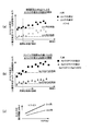
- 5 is a graph showing an example of a relationship between a difference in ⁇ torque due to a difference in a time interval or an engine speed and an acceleration G of a vehicle and a relationship between a vehicle speed and a permission determination threshold value according to the first embodiment of the present invention.
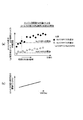
- 3 is a graph showing an example of a relationship between an integrated value of a ⁇ torque difference due to a difference in engine speed and acceleration G of a vehicle and a relationship between a vehicle speed and an abnormality determination time threshold value according to the first embodiment of the present invention. ..
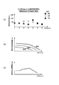
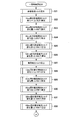
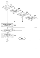
- 5 is a graph showing an example of a relationship between an abnormality determination time due to a difference in gear stage and a vehicle speed when an abnormality occurs according to the first embodiment of the present invention. It is a chart showing an example of behavior of abnormality detection of the vehicle-mounted control device according to the first embodiment of the present invention. It is a flow chart which shows an example of a series of processings performed by each part of an in-vehicle control device concerning a 1st embodiment of the present invention. 15 is a flowchart showing a detailed example of a process of calculating an allowable generated torque in step S17 of FIG. 14 and a process of calculating an estimated generated torque in step S18.
- 5 is a flowchart illustrating an example of abnormality detection permission determination processing performed by the abnormality detection unit according to the first embodiment of the present invention.
- 6 is a flowchart showing an example of abnormality determination processing performed by an abnormality detection unit according to the first embodiment of the present invention.
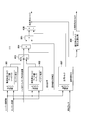
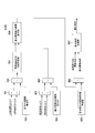
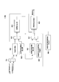
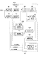
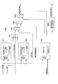
- It is a control block diagram which shows the internal structural example of the vehicle-mounted control apparatus which concerns on the 2nd Embodiment of this invention. It is a block diagram which shows the example of a schematic structure of the allowable horsepower calculation part which concerns on the 2nd Embodiment of this invention. It is a block diagram which shows the example of a schematic structure of the estimated generation
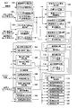
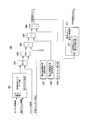
- FIG. 1 is a control block diagram showing an internal configuration example of the vehicle-mounted control device 217.
- the on-vehicle control device 217 is an example of a control device that is mounted on a vehicle and that can control the propulsive force of a drive source of the vehicle.
- the in-vehicle control device 217 according to the present embodiment has a function of monitoring whether or not the driving source generates a propulsive force greater than the propulsive force intended by the vehicle driver.
- the on-vehicle controller 217 includes blocks 101 to 115 shown in FIG.
- the vehicle-mounted control device 217 is used as an example of a control device that controls the operation of a drive source (engine 201: an example of an internal combustion engine).
- engine 201 an example of an internal combustion engine
- each of the blocks 101 to 115 will be described in order.
- the one-cylinder fuel injection section 116 to four-cylinder fuel injection section 119 and the one-cylinder ignition section 120 to four-cylinder ignition section 123, which will be described later, are attached to the engine 201 (see FIG. 2).
- the driving operation amount detection unit 101 detects the driving operation amount by calculating the accelerator opening degree of the driver.
- the engine rotation speed calculation unit 102 calculates an electrical signal from the crank angle sensor 219 (see FIG. 2) set at a predetermined crank angle position of the engine 201, mainly the number of inputs of a pulse signal change per unit time. By counting and performing arithmetic processing, the number of revolutions of the engine 201 per unit time (engine number of revolutions) is calculated.
- the cylinder inflow air amount calculation unit 103 calculates the amount of air flowing into the cylinder of the engine 201 (cylinder inflow air amount).
- the cylinder inflow air amount is calculated by using the intake air amount sensor signal representing the intake air amount detected by the intake air amount sensor 202 (see FIG. 2) set upstream of the intake system of the engine 201 and the intake pipe 205 (see FIG. 2). (See (1)), and the intake pipe pressure sensor signal representing the intake pipe pressure detected by the intake pipe pressure sensor 206 is set. Further, the cylinder inflow air amount calculation unit 103 calculates the load of the engine 201 based on the calculated cylinder inflow air amount and the engine rotation speed calculated by the engine rotation speed calculation unit 102.
- the basic fuel amount calculation unit 104 calculates the basic fuel required by the engine 201 in each region based on the engine speed calculated by the engine speed calculation unit 102 and the engine load calculated by the cylinder inflow air amount calculation unit 103. Calculate the amount.
- the basic ignition timing calculation unit 105 determines the optimum basic ignition timing in each region of the engine 201 based on the engine speed calculated by the engine speed calculation unit 102 and the engine load calculated by the cylinder inflow air amount calculation unit 103. To calculate.
- the ISC (Idol Speed Control) control unit 106 calculates a target rotation speed during idling and a target flow rate in order to keep the idling rotation speed of the engine 201 constant.
- the air-fuel ratio correction coefficient calculation unit 107 determines the difference between the output of the air-fuel ratio sensor 211 (FIG. 2 described later) set in the exhaust pipe of the engine 201 and the target air-fuel ratio described later, and the engine speed and the engine load described above. Based on this, the air-fuel ratio feedback correction coefficient is calculated.
- the target air-fuel ratio calculation unit 108 determines the target air-fuel ratio of the engine 201 based on the engine speed calculated by the engine speed calculation unit 102 and the engine load calculated by the cylinder inflow air amount calculation unit 103.
- the target throttle opening degree calculation unit 109 is requested by the driver based on the accelerator opening degree of the driver calculated by the driving operation amount detection unit 101 and the engine speed calculated by the engine speed calculation unit 102.
- the target torque is calculated, and the target throttle opening is calculated from the target torque.
- the allowable generated torque calculation unit calculates the allowable generated torque that can be generated by the drive source (engine 201). Therefore, the allowable generation torque calculation unit 110 determines the allowable generation torque based on the accelerator opening degree of the driver calculated by the driving operation amount detection unit 101 and the engine rotation speed calculated by the engine rotation speed calculation unit 102. calculate. The allowable generated torque calculation unit 110 also calculates the amount of change in the allowable generated torque used for abnormality detection, which will be described later.
- the estimated generated torque calculation unit calculates the estimated generated torque estimated to be generated in the drive source (engine 201) of the vehicle. Therefore, the estimated generated torque calculation unit 111 calculates the estimated generated torque based on the engine speed calculated by the engine speed calculation unit 102 and the engine load calculated by the cylinder inflow air amount calculation unit 103. Further, the estimated generated torque calculation unit 111 calculates the amount of change in the estimated generated torque used for detecting an abnormality, which will be described later.
- the abnormality detection unit 112 detects an abnormality from the change amount of the allowable generated torque and the change amount of the estimated generated torque described above. A configuration example and an operation example of the abnormality detection unit 112 will be described later with reference to FIG.
- the fuel correction unit 113 corrects the basic fuel amount calculated by the basic fuel amount calculation unit 104 for each cylinder of the engine 201 by the engine water temperature and the air-fuel ratio feedback coefficient of the air-fuel ratio correction coefficient calculation unit 107.
- the one-cylinder fuel injection unit 116 to four-cylinder fuel injection unit 119 inject fuel into each cylinder of the engine 201 based on the basic fuel amount corrected by the fuel correction unit 113.
- the ignition timing correction unit 114 corrects the basic ignition timing determined by the basic ignition timing calculation unit 105 by the engine water temperature for each cylinder of the engine 201, and performs advance or retard control.
- the one-cylinder ignition unit 120 to the four-cylinder ignition unit 123 ignite the fuel mixture flowing into the cylinder according to the basic ignition timing of the engine 201 corrected by the ignition timing correction unit 114.
- the electronically controlled throttle control unit 115 controls the electronically controlled throttle so that the throttle opening for ensuring the target flow rate during idling described above and the target throttle opening calculated by the target throttle opening calculation unit 109 are obtained. .. Further, when the abnormality detection unit 112 detects a torque increase abnormality of the engine 201, the electronically controlled throttle control unit 115 controls the electronically controlled throttle so as to eliminate the abnormality.
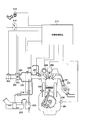
- FIG. 2 is a schematic diagram showing a configuration example of an auxiliary device provided in the peripheral portion of the engine 201.
- the engine 201 includes an intake air amount sensor (thermal air flow meter) 202 that measures the amount of air taken in by the engine 201, and a throttle throttle valve 203 that adjusts the amount of air taken in by the engine 201.
- the engine 201 includes an electronically controlled throttle motor 204 that operates a throttle throttle valve 203, a throttle opening sensor 215 that detects the opening of the throttle throttle valve 203, and an intake pipe that detects the pressure in the intake pipe installed in the intake pipe 205.
- a pressure sensor 206 is provided.
- the engine 201 also includes a fuel injection valve 207 (1 cylinder fuel injection section 116 to 4 cylinder fuel injection section 119 shown in FIG. 1) that supplies fuel required by the engine 201.
- the engine 201 also includes a crank angle sensor 219 that recognizes a protrusion set at a predetermined crank angle position in order to calculate the rotation speed of the engine 201.
- the engine 201 also includes a cam angle sensor 208 for recognizing a protrusion set at a predetermined cam angle position.
- the engine 201 supplies an ignition energy based on an ignition signal of the vehicle-mounted control device 217 to an ignition plug that ignites a mixture of fuel supplied into the cylinder.
- the ignition module 209 (one-cylinder ignition shown in FIG. 1). Parts 120 to 4 cylinder ignition part 123).
- the engine 201 is installed in a cylinder block of the engine 201 and detects a cooling water temperature of the engine 201.
- a water temperature sensor 210 is installed in front of a catalyst of an exhaust pipe of the engine 201, and is linear electrical with respect to oxygen concentration in exhaust gas.
- An air-fuel ratio sensor 211 that outputs a signal is provided.
- a canister purge tank 213 that adsorbs and holds fuel gas evaporated from the fuel tank 212 by charcoal or the like, and a canister purge valve 214 that allows the fuel gas adsorbed and held in the canister purge tank 213 to flow into the intake pipe by adjusting the opening degree.
- the vehicle is provided with an ignition key switch 216 which is a main switch for driving and stopping the engine 201, and an accelerator opening sensor 218 which detects an accelerator opening of a driver.
- Each auxiliary device shown in FIG. 2 is connected to an in-vehicle control device 217 that controls each auxiliary device of the engine 201.
- the in-vehicle control device 217 receives the signal transmitted from each auxiliary device, performs various calculations and processing, transmits a drive signal to a necessary auxiliary device, and controls the operation of the supplementary writing.
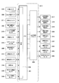
- FIG. 3 is a block diagram showing a hardware configuration example of the vehicle-mounted control device 217.
- an electric signal of each sensor installed in the engine 201 is converted into a signal for digital arithmetic processing, and a control signal for digital arithmetic is actually driven by an actuator.
- An I/O unit 302 for converting into a signal is set.
- the I/O unit 302 includes a water temperature sensor 210, a cam angle sensor 208, an air-fuel ratio sensor 211, an intake air amount sensor (thermal air flow meter) 202, a throttle opening sensor 215, and a vehicle speed sensor 309 for measuring the vehicle speed of the vehicle. , Ignition key switch 216, intake pipe pressure sensor 206, atmospheric pressure sensor 312, intake air temperature sensor 313, load SW 314 (for example, air conditioner switch), accelerator opening sensor 218, and crank angle sensor 219. To be done.
- An output signal driver 303 is connected to the CPU 301. Therefore, the CPU 301 performs a predetermined calculation and processing based on each signal input from the I/O unit 302, and then inputs a drive signal to the output signal driver 303.
- the output signal driver 303 transmits an output signal to the 1-cylinder fuel injection valve 317 to 4-cylinder fuel injection valve 320, the 1-cylinder ignition coil 321 to 4-cylinder ignition coil 324, and the electronically controlled throttle motor 204.
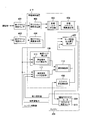
- FIG. 4 is a block diagram showing an example of the internal configuration of the vehicle-mounted control device 217 focusing on the part that detects the torque increase abnormality of the engine 201.
- the processing of each unit shown in FIG. 4 is realized by a program executed by the CPU 301 shown in FIG.
- the accelerator opening sensor 218 shown in FIG. 1 includes a first accelerator opening sensor 401 and a second accelerator opening sensor 402.
- the first accelerator opening degree sensor 401 and the second accelerator opening degree sensor 402 are both provided on the accelerator pedal and sense the accelerator operation amount of the accelerator operated by the driver's intention.
- the outputs from the first accelerator opening sensor 401 and the second accelerator opening sensor 402 have almost the same value.
- the value sensed by the first accelerator opening sensor 401 is output to the first accelerator opening calculation unit 403, and the value sensed by the second accelerator opening sensor 402 is output to the second accelerator opening calculation unit 404. ..
- the first accelerator opening degree calculation unit 403 and the second accelerator opening degree calculation unit 404 are included in the driving operation amount detection unit 101 of FIG.
- the first accelerator opening degree calculation unit 403 calculates the first accelerator opening degree based on the output sensed by the first accelerator opening degree sensor 401.
- the first accelerator opening is used by the target torque calculation unit 405 to calculate the target torque that is the target of the driver. Therefore, the target torque calculation unit (target torque calculation unit 405) calculates the target torque based on the accelerator opening (first accelerator opening) and the rotation speed of the drive source (engine 201).
- the target throttle opening degree calculation unit calculates the target throttle opening degree based on the target torque.
- the target throttle opening degree is used to control the opening degree of the throttle throttle valve 203 (see FIG. 2).
- the motor drive output signal calculation unit is a motor drive for driving a throttle motor (electrically controlled throttle motor 204) that opens the throttle throttle valve (throttle throttle valve 203) at a target throttle opening. Calculate the output signal.
- the electronically controlled throttle motor 204 causes the throttle throttle valve 203 attached to the intake system of the engine 201 to open and close based on the motor drive output signal output by the motor drive output signal calculation unit 407.
- the throttle opening sensor 215 senses the operation amount of the throttle throttle valve 203 and outputs a sensor signal to the throttle opening calculation unit 408.
- the throttle opening calculation unit (throttle opening calculation unit 408) is based on a sensor signal input from a throttle opening sensor (throttle opening sensor 215) that detects the throttle opening of the throttle throttle valve (throttle throttle valve 203). To calculate the throttle opening. At this time, the operation amount of the throttle throttle valve 203 is calculated as the actual throttle opening.
- the motor drive output signal calculation unit drives the motor based on the target throttle opening degree, the abnormality determination, and the throttle opening degree so that the throttle opening degree matches the target throttle opening degree. Performs feedback control of the output signal.
- the motor drive output signal calculation unit 407 compares the actual throttle opening degree input from the throttle opening degree calculation unit 408 with the target throttle opening degree input from the target throttle opening degree calculation unit 406. Then, the motor drive output signal calculation unit 407 performs feedback control of the motor drive output signal so that the actual throttle opening matches the target throttle opening.
- the electronically controlled throttle motor 204 controls the throttle opening of the throttle throttle valve 203 so that the actual throttle opening matches the target throttle opening.
- the motor drive output signal calculation unit (motor drive output signal calculation unit 407) performs a fail-safe process of reducing the torque generated by the drive source (engine 201) when the abnormality determination is input. As a result, the output of the engine 201 that has been determined to be abnormal is reduced, and torque abnormality of the engine 201 can be suppressed.
- the target torque calculation unit 405, the target throttle opening degree calculation unit 406, the motor drive output signal calculation unit 407, and the throttle opening degree calculation unit 408 described above are included in the target throttle opening degree calculation unit 109 of FIG. 1. ..
- the second accelerator opening degree calculation unit 404 calculates the second accelerator opening degree based on the output sensed by the second accelerator opening degree sensor 402.
- the required torque calculation unit calculates the required torque based on the driving state of the vehicle.
- the required torque is, for example, a collective expression of the target torque and the allowable generated torque.
- the driving state of the vehicle includes, for example, the second accelerator opening degree and the engine speed, but may include other parameters. Therefore, the required torque calculation unit 100 can calculate the required torque using parameters other than the second accelerator opening degree and the engine speed.
- the required torque calculation unit calculates the allowable generated torque that the drive source (engine 201) can generate. Part 110).
- the allowable generated torque calculation unit 110 calculates the allowable generated torque based on the second accelerator opening input from the second accelerator opening calculation unit 404 and the engine speed, and also changes the allowable generated torque for a predetermined time. The amount is also calculated.
- the estimated generated torque calculation unit 111 estimates the torque generated by the engine 201 based on the intake air amount indicating the state of the engine 201, the intake pipe pressure, and the engine speed, and also estimates the generated torque for a predetermined time. The change amount of is also calculated.
- the abnormality detection unit 112 detects an abnormality (for example, torque increase abnormality) of the drive source (engine 201).
- the abnormality detection unit detects an abnormality of the drive source (engine 201) based on the integrated value of the difference between the required torque change amount and the estimated generated torque change amount, The abnormality determination of the drive source (engine 201) is output.
- the abnormality detection unit determines whether the accumulated value of the difference between the allowable generated torque change amount and the estimated generated torque change amount and the operating state of the drive source (engine 201). The abnormality of the drive source (engine 201) is detected based on the result of comparison with the threshold value determined from.
- the abnormality detection unit 112 causes the allowable generated torque calculated by the allowable generated torque calculation unit 110, or the change amount of the allowable generated torque for a predetermined time, and the estimated generated torque calculated by the estimated generated torque calculation unit 111, or Based on the amount of change in the estimated generated torque for a predetermined time, it is monitored whether the engine 201 generates a torque equal to or higher than the target torque intended by the driver.
- the motor drive output signal calculation unit 407 operates the throttle throttle valve 203 to suppress the output of the engine 201.
- the motor drive output signal calculation unit 407 drives the electronically controlled throttle motor 204 so that the throttle throttle valve 203 moves in a direction in which the output of the engine 201 is suppressed, or stops the electronically controlled throttle motor 204 to mechanically operate. Then, the throttle throttle valve 203 is operated.
- FIG. 5 is a block diagram showing a schematic configuration example of the allowable generated torque calculation unit 110 shown in FIG.
- the allowable generated torque base value calculation unit 501 calculates the base value of the allowable generated torque based on the input engine speed and the second accelerator opening.
- the selection unit 502 calculates the allowable generated torque during the cruise by selecting the larger value of the base value of the allowable generated torque calculated by the allowable generated torque base value calculation unit 501 and the torque of the cruise request. It corresponds to.
- the selection unit 503 selects the smaller value of the torque guard request input from the outside and the allowable generated torque calculated by the selection unit 502, so that the allowable generated torque considering the torque guard request from the outside is selected. To calculate.
- the correction coefficient calculation unit 507 corresponding to the fuel property calculates a correction coefficient for considering a change amount of the torque generated by the engine 201 due to the fuel property.
- the integration unit 504 integrates the correction coefficient calculated by the correction coefficient calculation unit 507 with the allowable generated torque calculated by the selection unit 503 to calculate the allowable generated torque corresponding to the change in the generated torque due to the fuel property. ..
- the correction coefficient calculation unit 508 corresponding to the air density calculates a correction coefficient for considering a change in the torque generated by the engine 201 due to the air density.
- the integration unit 505 integrates the correction coefficient calculated by the correction coefficient calculation unit 508 with the allowable generated torque calculated by the integration unit 504 to calculate the allowable generated torque corresponding to the change in the generated torque due to the air density. ..
- the offset amount calculation unit 509 calculates the offset amount of the allowable generated torque.
- the offset amount adding unit 506 adds the offset amount calculated by the offset amount calculating unit 509 to the allowable generated torque calculated by the integrating unit 505, thereby taking into account an estimated generated torque calculation error described later, and when normal, Make sure that the estimated generated torque does not exceed the allowable generated torque.
- the allowable generated torque change amount calculation unit calculates the amount of change in the allowable generated torque per unit time as the allowable generated torque change amount ( ⁇ allowable generated torque).
- the allowable generation torque calculated by the offset amount adding unit 506 and the change amount of the allowable generation torque calculated by the allowable generation torque change amount calculation unit 510 for a predetermined time are the abnormalities detected by the abnormality detection unit 112. Used in the detection process.
- the required torque change amount calculation unit uses the amount of change in the required torque per unit time as the required torque change amount ( ⁇ required torque). calculate.
- FIG. 6 is a block diagram showing a schematic configuration example of the estimated generated torque calculation unit 111 shown in FIG.
- the estimated generated torque calculation unit (high octave) 601 calculates the base value of the estimated generated torque when the fuel is high octane gasoline, based on the engine speed and the engine load.
- the estimated generated torque calculation unit (regular) 602 calculates the base value of the estimated generated torque when the fuel is regular gasoline, based on the engine speed and the engine load.
- the estimated generated torque base value selection unit 603 determines the estimated generated torque based on the result of the property determination of gasoline used by the vehicle, that is, the determination result indicating whether the property of gasoline is high-octane or regular. Select the base value of.
- the integrating unit 604 integrates the ignition efficiency with the base value of the estimated generated torque in consideration of the influence of the ignition timing when measuring the base value of the estimated generated torque selected by the estimated generated torque base value selection unit 603. For example, if the ignition timing when the base value of the estimated generated torque is measured is used as a reference, the ignition efficiency becomes smaller than 1.0 when the ignition timing is on the retard side with respect to the reference ignition timing. As a result, the estimated generation torque is calculated to be small by the integration unit 604.
- the integrating unit 605 integrates the fuel injection amount correction value with respect to the estimated generated torque calculated by the integrating unit 604. For example, the integration unit 605 sets the correction value to 0 during fuel cut and integrates the estimated generated torque to set the fuel injection amount correction value to 0 so that the estimated generated torque during fuel cut becomes zero.
- the reason why the fuel injection amount correction value is set to 0 in this manner is to match the phenomenon that the generated torque of the engine 201 becomes 0 when fuel injection is not performed.
- the load torque calculation unit 607 calculates the load torque based on the engine speed and the intake pipe pressure.
- the subtracting unit 606 calculates the estimated generated torque as the axial torque of the engine 201 by subtracting the load torque from the estimated generated torque calculated by the integrating unit 605.
- the estimated generated torque change amount calculation unit calculates the amount of change in the estimated generated torque per unit time as the estimated generated torque change amount ( ⁇ estimated generated torque).
- the estimated generated torque change amount calculation unit 608 calculates the change amount of the estimated generated torque calculated by the subtraction unit 606 for a predetermined time.
- the estimated generation torque calculated by the subtraction unit 606 and the change amount of the estimated generation torque calculated by the estimated generation torque change amount calculation unit 608 for a predetermined time ( ⁇ estimated generation torque) are the abnormality detection processing performed by the abnormality detection unit 112. Used in.
- FIG. 7 is a block diagram showing a schematic configuration example of the abnormality detection unit 112 shown in FIG.
- the abnormality detection unit permits the abnormality detection when the difference between the allowable generated torque change amount ( ⁇ allowable generated torque) and the estimated generated torque change amount ( ⁇ estimated generated torque) becomes larger than the permission determination threshold value.
- the abnormality detection time is calculated as the abnormality detection time, and the abnormality detection time is continuously calculated until the abnormality detection time reaches the abnormality determination time threshold value.
- the permission determination threshold value is used by the abnormality detection unit (abnormality detection unit 112) to determine permission of abnormality detection of the drive source (engine 201), and has a different value depending on the vehicle speed of the vehicle and a predetermined time. To take.
- the permission determination threshold value is used when the ⁇ estimated generated torque and the ⁇ allowable generated torque are calculated. It takes different values depending on the predetermined time.
- the permission determination threshold may take different values depending on the rotation speed of the drive source (engine 201) and the predetermined time.
- the abnormality determination time threshold value is used to limit the time during which the difference between the required torque change amount and the estimated generated torque change amount is integrated.
- the difference calculating unit 701 calculates the change amount of the estimated generated torque calculated by the allowable generated torque change amount calculating unit 510 (see FIG. 5) for a predetermined time ( ⁇ estimated generated torque) and the estimated generated torque change amount. The difference of the amount of change ( ⁇ allowable generated torque) in the predetermined time of the allowable generated torque calculated by the unit 608 (see FIG. 6) is calculated. Then, the difference calculation unit 701 outputs the difference between the ⁇ estimated generated torque and the ⁇ allowable generated torque to the comparison unit 703 and the integration processing unit 705.
- the permission determination threshold value calculation unit 702 calculates a threshold value (a permission determination threshold value) that is used by the abnormality detection permission determination processing unit 704 to determine whether to permit the detection of the torque abnormality of the engine 201.
- the comparison unit 703 compares the difference between the ⁇ estimated generated torque and the ⁇ allowable generated torque calculated by the difference calculation unit 701 with the permission determination threshold value calculated by the permission determination threshold value calculation unit 702. Then, when the difference between the ⁇ estimated generated torque and the ⁇ allowable generated torque becomes larger than the permission determination threshold value, the determination result is output.
- the abnormality detection permission determination processing unit 704 determines that the abnormality detection permission is based on the determination result that the difference between the ⁇ estimated generated torque and the ⁇ allowable generated torque input from the comparison unit 703 is larger than the permission determination threshold value. The abnormality detection permission determination processing unit 704 determines that the abnormality detection permission is given during the period until the abnormality detection permission input from the comparison unit 708 is cleared. The abnormality detection permission determination processing unit 704 outputs the determined abnormality detection permission to the integration processing unit 705 and the abnormality detection time calculation unit 706.
- the integration processing unit 705 integrates the difference between the ⁇ estimated generated torque input from the difference calculation unit 701 and the ⁇ allowable generated torque while the abnormality detection permission is input. Then, the integration processing unit 705 outputs the integrated value of the difference between the ⁇ estimated generated torque and the ⁇ allowable generated torque to the comparison unit 710.
- the abnormality detection time calculation unit 706 calculates the time (hereinafter referred to as “abnormality detection time”) when the abnormality detection permission determination processing unit 704 determines that the abnormality detection is permitted.
- the abnormality detection time corresponds to, for example, time measured by a timer (not shown) included in the abnormality detection time calculation unit 706.
- the abnormality determination time threshold value calculation unit 707 calculates a threshold value (abnormality determination time threshold value) used for the comparison unit 708 for determining the length of the abnormality detection time period.
- the comparison unit 708 compares the abnormality detection time input from the abnormality detection time calculation unit 706 with the abnormality determination time threshold value input from the abnormality determination time threshold value calculation unit 707. Then, when the abnormality detection time becomes longer than the abnormality determination time threshold value, the comparison unit 708 clears the abnormality detection permission determination processing unit 704 to determine the abnormality detection permission. At the same time, the comparison unit 708 also clears the integrated value of the difference between the ⁇ estimated generated torque and the ⁇ allowable generated torque integrated by the integration processing unit 705.
- the comparison unit 708 clears the determination that the abnormality detection is permitted is output to the abnormality detection permission determination processing unit 704, and the determination that the abnormality detection permission is given from the abnormality detection permission determination processing unit 704 to the integration processing unit 705 is cleared.
- the integration processing unit 705 clears the integration value.
- the abnormality determination threshold value calculation unit 709 calculates an abnormality determination threshold value.
- the abnormality determination threshold value is used by the abnormality detection unit (abnormality detection unit 112) for detecting an abnormality of the drive source (engine 201) based on the integrated value (the integrated value of the difference between the ⁇ estimated generated torque and the ⁇ allowable generated torque). The value varies depending on the vehicle speed.
- the abnormality determination threshold may take different values depending on the rotation speed of the drive source (engine 201).
- the comparison unit 710 compares the integrated value of the difference between the ⁇ estimated generated torque and the ⁇ allowable generated torque accumulated by the accumulation processing unit 705 with the abnormality determination threshold value input from the abnormality determination threshold value calculation unit 709.
- the integrated value (the integrated value of the difference between the ⁇ estimated generated torque and the ⁇ allowable generated torque) takes a value near zero when the drive source (engine 201) is normal, and the drive source (engine 201) is abnormal. Is larger than the abnormality determination threshold.
- the comparison unit 710 determines the result of the abnormality determination as the motor drive output signal calculation unit 407 (see FIG. 4). ) Is output.
- the output of the abnormality determination by the comparison unit 710 is equivalent to the abnormality detection unit 112 detecting the abnormality.
- the abnormality detection unit calculates the integrated value (the integrated value of the difference between the ⁇ estimated generated torque and the ⁇ allowable generated torque) while the abnormality detection permission is determined, and the integrated value is When it becomes larger than the abnormality determination threshold determined based on the operating state of the drive source (engine 201), the abnormality of the drive source (engine 201) is detected and the abnormality determination is output.
- the motor drive output signal calculation unit 407 calculates the motor drive output signal so that the throttle throttle valve 203 closes. Then, a motor drive output signal is output to the electronically controlled throttle motor 204, the opening of the throttle throttle valve 203 is controlled, and the throttle throttle valve 203 is closed.
- the method of detecting the torque increase abnormality of the engine 201 may be other than the method performed by the abnormality detection unit 112 shown in FIG. 7. Therefore, with reference to FIGS. 8 and 9, a configuration example and an operation example of the abnormality detection units 112A and 410B capable of executing another method of detecting the torque increase abnormality of the engine 201 will be described.
- FIG. 8 is a block diagram showing a schematic configuration example of the abnormality detection unit 112A.
- the abnormality detection unit 112A shown in FIG. 8 uses the abnormality determination output from the comparison unit 710, which has already been described with reference to FIG. 7, together with the abnormality detection that monitors the state of the difference between the estimated generated torque and the allowable generated torque. Run the way. This method is performed in order to deal with the state in which the abnormality of the engine 201 cannot be detected only by the method performed by the abnormality detection unit 112 described with reference to FIG. 7. Therefore, the abnormality detection unit 112 in FIG. 7 and the abnormality detection unit 112A in FIG. 8 may operate in parallel.
- the abnormality detection unit 112A abnormality detection unit 112A
- the difference between the estimated generated torque and the allowable generated torque becomes larger than the difference abnormality determination threshold while it is determined that the abnormality detection is permitted.
- the difference abnormality detection time calculated in this case is compared with the difference abnormality determination time threshold value, and when the difference abnormality detection time becomes larger than the difference abnormality determination time threshold value, it is determined as the difference abnormality.
- the abnormality detection unit 112A can detect an abnormal deviation between the estimated generated torque and the allowable generated torque as an abnormality.
- the abnormality detection unit (abnormality detection unit 112A), based on the determined difference abnormality and the abnormality determination output based on the integrated value (the integrated value of the difference between the ⁇ estimated generated torque and the ⁇ allowable generated torque), The abnormality determination that takes into consideration the state of the difference between the estimated generated torque and the allowable generated torque is output.
- the abnormality detection unit (abnormality detection unit 112A) can avoid erroneously determining that the normal drive source (engine 201) is abnormal. An example of specific processing in each unit of the abnormality detection unit 112A will be described below.
- the operations of the difference calculation unit 701, the permission determination threshold value calculation unit 702, the comparison unit 703, and the abnormality detection permission determination processing unit 704 included in the abnormality detection unit 112A are the same as the operations of the corresponding units of the abnormality detection unit 112 illustrated in FIG. 7. Is. Then, the abnormality detection permission determined by the abnormality detection permission determination processing unit 704 is output to the differential abnormality detection time calculation unit 804.
- the difference calculation unit 801 calculates the difference between the estimated generated torque calculated by the estimated generated torque calculation unit 111 and the allowable generated torque calculated by the allowable generated torque calculation unit 110.
- the difference abnormality determination threshold value calculation unit 802 calculates a threshold value (a difference abnormality determination threshold value) used by the comparison unit 803 to determine a difference abnormality between the estimated generated torque and the allowable generated torque.
- the comparison unit 803 compares the difference between the estimated generated torque calculated by the difference calculation unit 801 and the allowable generated torque with the difference abnormality determination threshold value calculated by the difference abnormality determination threshold value calculation unit 802. When the difference between the estimated generated torque and the allowable generated torque is larger than the difference abnormality determination threshold, the comparison unit 803 determines that the difference abnormality has occurred, and outputs the difference abnormality generation to the difference abnormality detection time calculation unit 804.
- the differential abnormality detection time calculation unit 804 determines whether the abnormality detection permission is satisfied. The time during which the estimated generated torque is larger than the allowable generated torque (differential abnormality detection time) is calculated.
- the difference abnormality determination time threshold value calculation unit 805 calculates a difference abnormality determination time threshold value.
- the difference abnormality determination time threshold value is used by the comparing unit 806 to determine that the difference abnormality detection time is larger than this threshold value.
- the comparison unit 806 compares the difference abnormality detection time calculated by the difference abnormality detection time calculation unit 804 with the difference abnormality determination time threshold value calculated by the difference abnormality determination time threshold value calculation unit 805, and compares the comparison result with the abnormality determination process. It is output to the unit 807.
- the comparison result includes a result (differential abnormality determination) that the comparing unit 806 determines as a differential abnormality when the time during which the estimated generated torque is greater than the allowable generated torque is greater than the differential abnormality determination time threshold value. Be done.
- the abnormality determination processing unit 807 outputs the abnormality determination result obtained from the integrated value of the difference between the ⁇ estimated generated torque and the ⁇ allowable generated torque output from the comparison unit 710 of FIG. A final abnormality determination is performed based on the determination result of the difference abnormality between the generated torque and the allowable generated torque. Thereby, the abnormality determination processing unit 807 can perform the abnormality determination in consideration of the state of the difference between the estimated generated torque and the allowable generated torque. Then, the abnormality determination processing unit 807 outputs the final result of the abnormality determination to the motor drive output signal calculation unit 407 (see FIG. 4).
- FIG. 9 is a block diagram showing a schematic configuration example of the abnormality detection unit 112B.
- the abnormality detection unit determines that a temporary abnormality occurs when the integrated value (the integrated value of the difference between the ⁇ estimated generated torque and the ⁇ allowable generated torque) becomes larger than the temporary abnormality determination threshold.
- the temporary abnormality determination time which is the period to be determined, is longer than the temporary abnormality determination time threshold value and the integrated value is larger than the abnormality determination integrated value threshold value, the abnormality determination is output. Accordingly, the abnormality detection unit 112B can determine that the integrated value is a value calculated due to the torque increase abnormality of the engine 201 after determining whether or not there is a temporary abnormality in the integrated value calculated first. ..
- an example of specific processing in each unit of the abnormality detection unit 112B will be described.
- the operation of the difference calculating unit 701 included in the abnormality detecting unit 112B is similar to the operation of the difference calculating unit 701 included in the abnormality detecting unit 112 illustrated in FIG. Then, the difference calculation unit 701 outputs the calculated difference between the ⁇ estimated generated torque and the ⁇ allowable generated torque to the integration processing unit 901.
- the integration processing unit 901 integrates the difference between the ⁇ estimated generated torque calculated by the difference calculation unit 701 and the ⁇ allowable generated torque, and outputs the integrated value to the comparison unit 903 and the abnormality determination processing unit 909.
- the comparison unit 907 described later outputs a comparison result that the temporary abnormality determination time is larger than the temporary abnormality determination time threshold value. In the meantime.
- the temporary abnormality determination threshold value calculation unit 902 calculates a temporary abnormality determination threshold value (temporary abnormality determination threshold value) used in the comparison unit 903.
- the comparison unit 903 compares the integrated value of the difference between the ⁇ estimated generated torque calculated by the integration processing unit 901 and the ⁇ allowable generated torque with the temporary abnormality determination threshold value calculated by the temporary abnormality determination threshold value calculation unit 902, and compares them. Output the result.
- the temporary abnormality determination unit 904 determines that the temporary abnormality is detected when the integrated value of the difference between the ⁇ estimated generated torque and the ⁇ allowable generated torque is larger than the temporary abnormality determination threshold value. Then, the temporary abnormality determination unit 904 outputs the determination result of the temporary abnormality to the temporary abnormality determination time calculation unit 905 and the abnormality determination processing unit 909.
- the temporary abnormality determination time calculation unit 905 calculates the time (temporary abnormality determination time) for the temporary abnormality determination unit 904 to determine the temporary abnormality based on the determination result of the temporary abnormality input from the temporary abnormality determination unit 904.
- the temporary abnormality determination time corresponds to, for example, time measured by a timer (not shown) included in the temporary abnormality determination time calculation unit 905.
- the temporary abnormality determination time threshold calculation unit 906 calculates the temporary abnormality determination time threshold value used in the comparison unit 907.
- the comparison unit 907 compares the temporary abnormality determination time calculated by the temporary abnormality determination time calculation unit 905 with the temporary abnormality determination time threshold value calculated by the temporary abnormality determination time threshold value calculation unit 906, and adds the comparison result to the integration processing unit. It outputs to 901 and the abnormality determination process part 909.
- the abnormality determination integrated value threshold value calculation unit 908 calculates an abnormality determination integrated value threshold value (abnormality determination integrated value threshold value) used in the abnormality determination processing unit 909, and outputs it to the abnormality determination processing unit 909.
- the integrated value of the difference between the ⁇ estimated generated torque and the ⁇ allowable generated torque is input from the integration processing unit 901, and the temporary abnormality determination result is input from the temporary abnormality determination unit 904.
- the comparison result of the temporary abnormality determination time is input from the comparison unit 907 to the abnormality determination processing unit 909, and the abnormality determination integrated value threshold value is input from the abnormality determination integrated value threshold value calculation unit 908.
- the abnormality determination processing unit 909 determines that the temporary abnormality determination unit 904 determines that the temporary abnormality determination time is greater than the abnormality determination integrated value threshold value based on the comparison result of the temporary abnormality determination time.
- the increase integrated value of the integrated value of the difference between the ⁇ estimated generated torque and the ⁇ permissible generated torque accumulated from is compared with the abnormality determination integrated value threshold value.
- the abnormality determination processing unit 909 makes a final abnormality determination when the increment integrated value of the integrated value of the difference between the ⁇ estimated generated torque and the ⁇ allowable generated torque is larger than the abnormality determination integrated value threshold. ..
- the abnormality determination processing unit 909 outputs the final result of the abnormality determination to the motor drive output signal calculation unit 407 (see FIG. 4).
- FIG. 10 is a graph showing an example of the relationship between the difference in ⁇ torque due to the difference in the time interval or the engine speed and the acceleration G of the vehicle, and the relationship between the vehicle speed and the permission determination threshold.
- the difference in ⁇ torque described in the figure represents the difference between the change amount of the estimated generated torque for a predetermined time ( ⁇ estimated generated torque) and the change amount of the allowable generated torque for a predetermined time ( ⁇ allowable generated torque).
- the graph (a) of FIG. 10 shows the difference in ⁇ torque due to the difference in the time interval ⁇ t when the throttle throttle valve 203 is opened stepwise while the gear of the transmission is fixed and the predetermined engine speed state is maintained.
- An example of the relationship between the acceleration and the acceleration G is shown.
- the time intervals at which the amount of change ( ⁇ estimated generated torque and ⁇ allowable generated torque) are calculated are t1 and t2.
- the interval of t1 ( ⁇ t1) is made larger than the interval of t2 ( ⁇ t2).
- the acceleration G represented as "dangerous acceleration G area" in the graph is, for example, 0.2 G or more.
- a threshold value permits detection of a dangerous state of the vehicle, that is, an abnormal state of the engine 201 for each ⁇ t1 and ⁇ t2. It is necessary to set a plurality of permission judgment threshold values. For example, as shown in the figure, a threshold for ⁇ t1 and a threshold for ⁇ t2 are set.
- the time interval is set to one state and the state of the engine speed to be held is confirmed as two types (Ne1, Ne2) in the graph (a) of FIG. 10, and the engine speed is confirmed.
- 6 is a graph showing an example of the relationship between the difference in ⁇ torque and the acceleration G due to the difference in Ne.
- the engine speeds at which the change amounts ( ⁇ estimated generated torque and ⁇ allowable generated torque) are calculated are Ne1 and Ne2.
- the engine speed Ne1 is higher than Ne2.
- the vehicle speed VSP1 is greater than the vehicle speed VSP2.
- the vehicle speed VSP1 is 50 [km/h] and the vehicle speed VSP2 is 10 [km/h].
- Ne1 VSP1 in which the vehicle speed is high
- Ne2 VSP2 in which the vehicle speed is low
- Ne1 VSP1
- Ne2 VSP2 in which the vehicle speed is low
- the vehicle is in a dangerous state (abnormal state) for each of engine speeds Ne1 (VSP1) and Ne2 (VSP2).
- the threshold value shown in the drawing is larger in Ne1 (VSP1) than in Ne2 (VSP2).
- the graph (c) in FIG. 10 is a graph showing an example of the relationship between the vehicle speed VSP (engine speed Ne) and the ⁇ torque difference threshold value ( ⁇ Nm).
- the ⁇ torque difference threshold value ( ⁇ Nm) corresponds to the permission determination threshold value calculated by the permission determination threshold value calculation unit 702 shown in FIG. 7.
- the permission determination threshold value is set to the engine speed (Ne) or the vehicle speed (VSP) for each time interval (each ⁇ t1, ⁇ t2). It can be seen that a plurality of variable thresholds are set by.
- FIG. 11 is a graph showing an example of the relationship between the integrated value of the ⁇ torque difference due to the difference in engine speed and the acceleration G of the vehicle, and the relationship between the vehicle speed and the abnormality determination time threshold value.
- the graph (a) of FIG. 11 shows that the integrated value of the difference in ⁇ torque and the acceleration G of the acceleration G when the throttle throttle valve 203 is opened stepwise while the gear of the transmission is fixed and the predetermined engine speed state is maintained.
- An example of the relationship is shown.
- This graph (a) is represented as a result of confirming the state of the engine speed with two types (Ne1, Ne2). As described above, the engine speed Ne1 is higher than the Ne2.
- the vehicle speeds at the engine speeds Ne1 and Ne2 are represented as vehicle speeds VSP1 and VSP2, respectively, for fixing the gears, the vehicle speed VSP1 is higher than the vehicle speed VSP2.
- the integrated value of the ⁇ torque difference when the vehicle has generated a predetermined acceleration G or more is more in the case of Ne1 where the engine speed is high (VSP1 where the vehicle speed is high) (indicated by the diagonal square mark in the figure).
- the engine speed is higher than that in the case of Ne2 (VSP2 in which the vehicle speed is low) (represented by a hexagonal mark in the figure). Therefore, assuming that the vehicle is in a dangerous state when the vehicle has generated a predetermined acceleration G or more, a dangerous state (abnormal state) of the vehicle is detected for each of Ne1 (VSP1) and Ne2 (VSP2).
- a dangerous state (abnormal state) of the vehicle is detected for each of Ne1 (VSP1) and Ne2 (VSP2).
- the graph (b) of FIG. 11 is a graph showing an example of the relationship between the vehicle speed VSP (engine speed Ne) and the threshold ( ⁇ Nm) of the ⁇ torque difference integrated value.
- the threshold value ( ⁇ Nm) of the ⁇ torque difference integrated value corresponds to the abnormality determination threshold value calculated by the abnormality determination threshold value calculation unit 709 shown in FIG. 7. Then, as described with reference to the graph (a) of FIG. 11, it is understood that the abnormality determination threshold needs to be a threshold that is variable depending on the engine speed (Ne) or the vehicle speed (VSP).
- FIG. 12 is a graph showing an example of the relationship between the abnormality determination time due to the difference in gear position and the vehicle speed when the abnormality occurs.
- the graph (a) of FIG. 12 shows the abnormality determination time [ms] (time until the integrated value reaches the threshold value) required to calculate the integrated value for detecting the abnormal state, which is shown in FIG. It is an example of a relationship with a vehicle speed (VSP) [km/h] when an abnormality occurs in each gear. Therefore, in the graph (a), the abnormality determination time measured when the throttle throttle valve 203 is opened stepwise while changing the transmission gear and maintaining a predetermined vehicle speed state (engine speed state) is plotted. To be done.
- VSP vehicle speed
- the High gear side calculates the integrated value for detecting the abnormal state.
- the time required for (abnormality determination time) is long.
- the figure shows a state in which the abnormality determination time is plotted for each vehicle speed (VSP) of 10 [km/h] using a triangular mark for the first speed, an oblique square mark for the second speed, and a pentagonal mark for the third speed.
- the graph (b) in FIG. 12 shows an example of the relationship between the vehicle speed [km/h] and the abnormality determination time threshold value [ms].
- a graph showing the relationship between the vehicle speeds for the first speed, the second speed, the third speed, and the abnormality determination time threshold value is shown.
- the abnormality determination time threshold value calculated by the abnormality determination time threshold value calculation unit 707 shown in FIG. 7 needs to be set as a variable threshold value at the vehicle speed (VSP) for each gear stage of the transmission. is there.
- the abnormality determination time threshold value can be set by another method.
- the graph (c) of FIG. 12 shows another example of the relationship between the vehicle speed [km/h] and the abnormality determination time threshold value [ms]. As shown in the graph (c), the abnormality determination time threshold value calculated by the abnormality determination time threshold value calculation unit 707 shown in FIG. 7 needs to be set to the maximum time so as to cover all gears.
- FIG. 13 is a chart showing an example of an abnormality detection behavior of the vehicle-mounted control device 217.
- lines 1301 to 1313 represent values calculated by the respective units of the vehicle-mounted control device 217.
- the line 1301 represents the accelerator opening degree, which indicates the accelerator depression amount of the driver.
- the accelerator opening is a value calculated by the driving operation amount detection unit 101.
- a line 1301 shows how the accelerator opening changes when the vehicle accelerates, runs at a constant speed, or decelerates.
- a line 1302 represents the allowable generated torque calculated by the allowable generated torque calculation unit 110. It is shown that the allowable generated torque increases as the accelerator opening increases (acceleration state), and decreases as the accelerator opening decreases (deceleration state). Therefore, the line 1302 shows how the allowable generated torque changes in accordance with the change in the accelerator opening.
- a line 1303 represents the estimated generated torque calculated by the estimated generated torque calculation unit 111.
- Line 1303 indicates that the behavior during acceleration and deceleration is delayed with respect to the operation of the accelerator opening due to the influence of response delay of intake air and the like. Note that the present embodiment shows a situation in which the estimated generated torque increases due to the occurrence of an abnormality from the time point A.
- a line 1304 represents the amount of change in permissible torque generated per unit time ( ⁇ permissible torque) calculated by the permissible torque change amount calculation unit 510.
- a line 1305 represents the amount of change in estimated generated torque calculated by the estimated generated torque change amount calculation unit 608 per unit time ( ⁇ estimated generated torque).
- a line 1306 represents the difference between the ⁇ estimated generated torque calculated by the difference calculation unit 701 and the ⁇ allowable generated torque.
- a line 1307 represents a permission determination threshold value for the abnormality detection permission determination processing unit 704 to determine the abnormality detection permission.
- a line 1308 is an abnormality detection measured by the timer of the abnormality detection time calculation unit 706 when the difference between the ⁇ estimated generated torque and the ⁇ allowable generated torque represented by the line 1306 becomes larger than the permission determination threshold.
- a line 1309 represents the abnormality determination time threshold value for limiting the measurement of the abnormality detection time, which is calculated by the abnormality determination time threshold value calculation unit 707. It can be seen that the abnormality detection time represented by the line 1308 is counted until the abnormality determination time threshold represented by the line 1309 is reached.
- a line 1310 represents the setting state of the permission flag included in the abnormality detection permission determination processing unit 704.
- the permission flag is turned on to indicate the abnormality detection permission.
- the permission flag is turned off.
- the ⁇ allowable generated torque is subtracted from the ⁇ estimated generated torque, so that the difference in the acceleration state has a negative value. Then, when the vehicle is traveling at a constant speed, the difference becomes larger than the permission determination threshold value. At the timing when the difference becomes larger than the permission determination threshold value, the timer for measuring the abnormality detection time is activated as shown in line 1308, and the permission flag shown in line 1310 is turned on to determine the abnormality detection permission.
- the timer is cleared and the abnormality detection time returns to zero. Also, the permission flag is turned off, and the line 1310 returns to Low.
- the reason for setting the abnormality determination time threshold value is that it is difficult to make the value of the line 1306 always 0 by perfectly matching the phases of the permissible generated torque after the filter processing and the estimated generated torque even in the normal time. This is because. Since always integrating leads to erroneous detection of an abnormal state, an abnormality determination time threshold value is provided to improve the detection accuracy of the abnormal state.
- a line 1311 shows how the difference between the ⁇ estimated generated torque and the ⁇ allowable generated torque shown in the line 1306 is integrated while the permission flag shown in the line 1310 is on.
- a line 1312 represents an abnormality determination threshold value used by the comparison unit 710 for abnormality determination.
- a line 1313 represents the setting state of the abnormality determination flag included in the comparison unit 710. The comparison unit 710 turns on the abnormality determination flag when the line 1313 is High, and outputs the abnormality determination. On the other hand, the comparison unit 710 does not output the abnormality determination because the abnormality determination flag is turned off when the line 1313 is Low.
- the comparison unit 710 shown in FIG. Output the judgment. Then, the comparing unit 710 sets the abnormality determination flag shown in the line 1313 as the abnormality determination. As described above, when the abnormality detection unit (abnormality detection unit 112) determines that the abnormality detection is permitted, the integrated value (the integrated value of the difference between the ⁇ estimated generated torque and the ⁇ allowable generated torque) becomes larger than the abnormality determination threshold value. The abnormality judgment is output to.
- this accumulated value is not the abnormality determination threshold value if it is not in an abnormal state. Does not exceed Therefore, it is possible to eliminate the possibility that the abnormality detection unit 112 may erroneously determine that the engine 201 is in the abnormal state even when the engine 201 is in the normal state.
- FIG. 14 is a flowchart showing an example of a series of processes performed by each unit of the vehicle-mounted control device 217.
- each step will be described with reference to each control block forming the vehicle-mounted control device 217 shown in FIG.
- the driving operation amount detection unit 101 converts the output voltage from the accelerator opening sensor 218 into an accelerator opening ratio and reads it (S1). For example, if the accelerator is fully opened, the accelerator opening ratio is converted to 100%.
- the engine rotation speed calculation unit 102 counts the number of electric signals from the crank angle sensor 219, mainly the number of inputs of the pulse signal change per unit time, and calculates the engine rotation speed by calculation processing (S2). ..
- the target throttle opening calculation unit 406 calculates and reads the target throttle opening based on the target torque calculated by the target torque calculation unit 405 (S3).
- the throttle opening degree calculation unit 408 converts the throttle opening degree sensor output voltage from the throttle opening degree sensor 215 into the throttle opening degree and reads it.
- the cylinder inflow air amount calculation unit 103 reads the cylinder inflow air amount (engine load) converted based on the output voltage of the intake air amount sensor (thermal air flow meter) 202 (S4).
- the basic fuel amount calculation unit 104 calculates the basic fuel amount based on the engine speed and the cylinder inflow air amount (engine load) (S5).
- the fuel correction unit 113 performs a map search for the basic fuel correction coefficient from the engine speed and the engine load, and calculates the basic fuel correction coefficient (S6).
- the air-fuel ratio correction coefficient calculation unit 107 reads the actual air-fuel ratio obtained by converting the output voltage of the air-fuel ratio sensor 211 into the air-fuel ratio (S7).
- the target air-fuel ratio calculation unit 108 performs a map search for the target air-fuel ratio based on the engine speed and the engine load, and searches for the target air-fuel ratio (S8).
- the air-fuel ratio correction coefficient calculation unit 107 performs feedback control to the target air-fuel ratio with the target air-fuel ratio and the actual air-fuel ratio, and calculates the air-fuel ratio correction coefficient (S9).
- the fuel correction unit 113 corrects the basic fuel amount by the basic fuel correction coefficient and the air-fuel ratio correction coefficient by the feedback control, and calculates the fuel injection amount (S10).
- the ISC control unit 106 calculates the target value of the idle speed (ISC target speed) (S11), and calculates the ISC target flow rate that can realize the target value of the idle speed (S12). Then, the ISC control unit 106 calculates the required opening degree based on the ISC target flow rate (S13).
- the basic ignition timing calculation unit 105 calculates the basic ignition timing of the engine 201 based on the engine speed and the engine load (S14).
- the ignition timing correction unit 114 performs water temperature correction or the like on the basic ignition timing based on the water temperature correction amount (S15), and sets the corrected ignition timing in the one-cylinder fuel injection unit 116 to four-cylinder fuel injection unit 119 ( S16).
- the allowable generated torque calculation unit 110 calculates the allowable generated torque (S17).
- the estimated generated torque calculation unit 111 calculates the estimated generated torque (S18).
- the abnormality detection unit 112 detects the abnormality of the engine 201 based on the allowable generated torque and the estimated generated torque (S19).
- the electronically controlled throttle control unit 115 causes the target throttle opening calculation unit 109 to calculate the required opening amount from the target torque calculated from the accelerator opening and the engine speed, and the ISC control unit 106 calculates the required opening amount from the ISC target flow rate.
- the throttle throttle valve 203 is controlled to the final throttle opening based on the opening (S20). Even when an abnormality of the engine 201 is detected in step S19, the electronically controlled throttle control unit 115 controls the throttle opening degree of the throttle throttle valve 203 (S20).
- This abnormality detection process is an interrupt process performed at regular intervals.
- FIG. 15 is a flowchart showing a detailed example of the process of calculating the allowable generated torque in step S17 of FIG. 14 and the process of calculating the estimated generated torque in step S18.
- the allowable generated torque calculation unit 110 calculates the allowable generated torque (S21).
- the allowable generated torque change amount calculation unit (allowable generated torque calculation unit 110) calculates a plurality of different allowable generated torque change amounts per unit time with the same starting point. For example, the allowable generated torque calculation unit 110 sequentially calculates the amount of change in the allowable generated torque ( ⁇ 10LT, ⁇ 40LT, ⁇ 80LT, ⁇ 120LT, ⁇ 160LT) for 10 ms, 40 ms, 80 ms, 120 ms, and 160 ms with the same starting point. (S22-S26).
- the starting points for calculating the amount of change in the allowable generated torque are at the same timing. For example, 10 ms in step S22, 40 ms in step S23, etc. all represent the elapsed time from the same starting point 0.
- the estimated generated torque calculation unit 111 calculates the estimated generated torque (S27).
- the estimated generated torque change amount calculation section calculates a plurality of different estimated generated torque change amounts per unit time with the same starting point. For example, the estimated generated torque calculation unit 111 sequentially calculates the change amount ( ⁇ 10ET, ⁇ 40ET, ⁇ 80ET, ⁇ 120ET, ⁇ 160ET) of the estimated generated torque for 10 mS, 40 ms, 80 ms, 120 ms, and 160 ms with the same starting point. (S28 to S32). Even in this case, the starting points for calculating the change amount of the estimated generated torque are at the same timing. After step S32, the process moves to step S41 of FIG.
- FIG. 16 and 17 are flowcharts showing a detailed example of the abnormality detection process performed in step S19 of FIG.
- the abnormality detection unit 112 performs the processing of each step.
- FIG. 16 is a flowchart showing an example of the abnormality detection permission determination process performed by the abnormality detection unit 112.
- the abnormality detection unit (abnormality detection unit 112) permits the abnormality detection when the difference between the estimated generated torque change amount calculated for each same unit time and the allowable generated torque change amount becomes larger than the permission determination threshold value. To determine.
- step S41 determines whether the difference between the estimated generated torque change amount ( ⁇ 80ET) and the allowable generated torque change amount ( ⁇ 80LT) for 80 ms is larger than the permission determination threshold value (KD80H). Check (S42).
- step S43 determines whether the difference between the estimated generated torque change amount ( ⁇ 160ET) and the allowable generated torque change amount ( ⁇ 160LT) for 160 ms is larger than the permission determination threshold value (KD160H). Check (S44).
- step S46 If the check result in step S46 is Yes, the abnormality detection unit 112 counts up the timer (DPCN) for measuring the abnormality detection time (S47), and proceeds to step S51 in FIG. If the check result in step S46 is No, the abnormality detection unit 112 ends the flow.
- DPCN timer for measuring the abnormality detection time
- FIG. 17 is a flowchart showing a detailed example of the abnormality determination processing performed by the abnormality detection unit 112.
- the abnormality detection unit 112 checks whether the abnormality detection time measured by the abnormality detection time measurement timer (DPCN) is larger than the abnormality determination time threshold value (KDPCN) (S51). That is, it is checked whether the elapsed time after the abnormality detection is permitted exceeds the abnormality determination time threshold value. If the check result in step S51 is No, the abnormality detection unit 112 calculates the difference (change amount difference: SMD) between the estimated generated torque change amount ( ⁇ 10ET) and the allowable generated torque change amount ( ⁇ 10LT) for 10 ms. (S52).
- SMD change amount difference
- TSMD integrated value of the change amount difference
- KTSMD abnormality determination threshold value
- DPCN abnormality detection time measuring timer
- TSMD integrated value
- the engine 201 generates excessive torque based on the integrated value of the difference between the change amount of the allowable generated torque and the change amount of the estimated generated torque.
- the occurrence of such a torque abnormality of the engine 201 can be determined.
- the in-vehicle control device 217 determines whether or not a torque abnormality of the engine 201 that causes the engine 201 to generate excessive torque is generated based on the integrated value of the difference between the change amount of the required torque and the change amount of the estimated generated torque. It can also be determined. Therefore, the abnormality detection unit 112 can determine a torque abnormality in which the torque generated by the engine 201 is larger than the driver's intention due to, for example, an abnormality in the throttle throttle valve 203.
- the torque increase abnormality of the engine 201 is determined based on the driving operation change amount and the operation state change amount of the engine 201.
- the influence of variations in sensors (such as sensors for detecting the operating state) can be suppressed.
- the torque increase abnormality of the engine 201 is determined based on the amount of change for a predetermined time (for example, between 40 ms and 160 ms), acceleration unintended by the driver can be suppressed, and risk avoidance of the driver can be sufficiently avoided. ..
- the on-vehicle control device In the on-vehicle control device according to the first embodiment described above, it is possible to detect an abnormality from the allowable generated torque calculated from the accelerator opening degree of the driver and the estimated generated torque calculated based on the engine speed and the engine load. Abnormality was detected in the dimension of torque.
- the in-vehicle control device may be configured to perform abnormality detection in another dimension, for example, the dimension of horsepower. Therefore, in the vehicle-mounted control device according to the second embodiment, the horsepower is calculated instead of the torque, and the engine 201 is calculated based on the integrated value of the difference between the change amount of the allowable generated horsepower and the change amount of the estimated generated horsepower. It is possible to determine the abnormal increase in horsepower.
- a configuration example of a functional block that obtains the change amount of the allowable generated horsepower and the change amount of the estimated generated horsepower will be described with reference to FIGS. 18 to 20.
- FIG. 18 is a control block diagram showing an internal configuration example of the on-vehicle control device 217A according to the second embodiment.
- the on-vehicle control device 217A includes the required torque calculation unit 100, the allowable generation torque calculation unit 110, the estimated generation torque calculation unit 111, and the abnormality detection unit 112 of the on-vehicle control device 217 shown in FIG.
- the allowable generated horsepower calculation unit 110A, the estimated generated horsepower calculation unit 111A, and the abnormality detection unit 112A are replaced.
- the required horsepower calculation unit calculates the required horsepower based on the driving state of the vehicle. Further, when the allowable generated horsepower is used for processing, the required horsepower calculation unit (required horsepower calculation unit 100A) calculates the allowable generated horsepower that can be generated by the drive source (engine 201). Part 110A). The estimated generated horsepower calculation unit (estimated generated horsepower calculation unit 111A) calculates the estimated generated horsepower estimated to be generated in the drive source (engine 201) of the vehicle.
- the abnormality detection unit 112A detects an abnormality in the drive source (engine 201).
- the abnormality detection unit 112A according to the second embodiment is used to calculate the various processes calculated using torque in the first embodiment using horsepower.
- the abnormality detection unit detects an abnormality of the drive source (engine 201) based on the integrated value of the difference between the required horsepower change amount and the estimated generated horsepower change amount. It is detected and the abnormality determination of the drive source (engine 201) is output.
- abnormality detection unit 112A determines the cumulative value of the difference between the allowable generated horsepower change amount and the estimated generated horsepower change amount and the operating state of the drive source (engine 201).
- the abnormality of the drive source (engine 201) is detected based on the result of comparison with the threshold value determined from.
- FIG. 19 is a block diagram showing a schematic configuration example of the allowable generated horsepower calculation unit 110A.
- the allowable generated horsepower calculation unit 110A includes an offset amount addition unit 506 and an allowable generated torque change amount calculation unit 510 in the allowable generated torque calculation unit 110 shown in FIG.
- the calculation unit 510A is replaced.
- the offset amount addition unit 506A adds the offset amount calculated by the offset amount calculation unit 509 to the allowable generated horsepower obtained by converting the allowable generated torque calculated by the integration unit 505. By adding the offset amount to the allowable generated horsepower, the estimated generated horsepower is prevented from becoming larger than the allowable generated horsepower in a normal state in consideration of the calculation error of the estimated generated horsepower.
- the allowable generated horsepower change amount calculation unit 510A calculates the amount of change in the allowable generated horsepower for a predetermined time.
- the allowable generated horsepower calculated by the allowable generated horsepower change amount calculation unit 510A and the change amount of the allowable generated horsepower for a predetermined time ( ⁇ allowable generated horsepower) are used by the abnormality detection unit 112A.
- the required horsepower change amount calculation unit calculates the amount of change in the allowable generated horsepower per unit time as the allowable generated horsepower change amount. It is a horsepower change amount calculation unit (allowable generated horsepower change amount calculation unit 510A).
- the required horsepower change amount calculation unit calculates the amount of change in the required horsepower per unit time as the required horsepower change amount.
- FIG. 20 is a block diagram showing a schematic configuration example of the estimated generated horsepower calculation unit 111A.
- the estimated generated horsepower calculation unit 111A includes a subtraction unit 606 and an estimated generated torque change amount calculation unit 608 in the estimated generated torque calculation unit 111 illustrated in FIG. 6, which are respectively included in the subtraction unit 606A and the estimated generated horsepower change amount calculation unit 608A. The configuration is replaced.
- the subtracting unit 606A calculates the estimated generated horsepower as the axial horsepower of the engine 201 by converting the estimated generated torque obtained by subtracting the load torque from the estimated generated torque calculated by the integrating unit 605 into the estimated generated horsepower.
- the estimated generated horsepower change amount calculation unit calculates the amount of change in the estimated generated horsepower per unit time as the estimated generated horsepower change amount. Therefore, the estimated generated horsepower change amount calculation unit 608A calculates the change amount of the estimated generated horsepower calculated by the subtraction unit 606A for a predetermined time.
- the estimated generated horsepower calculated by the estimated generated horsepower change amount calculation unit 608A and the change amount of the estimated generated horsepower for a predetermined time are used in the abnormality detection process performed by the abnormality detection unit 112A.
- the allowable generated horsepower, the change amount of the allowable generated horsepower in the predetermined time period, the estimated generated horsepower, and the change amount of the estimated generated horsepower in the predetermined time period are appropriately used to determine the abnormality.
- the detection unit 112A detects the abnormality of the engine 201, the abnormality determination is output. Therefore, the in-vehicle control device 217A determines whether the engine 201 has abnormal horsepower that causes excessive engine power based on the integrated value of the difference between the allowable amount of change in horsepower and the estimated amount of change in horsepower. Occurrence can be determined.
- the in-vehicle control device 217 detects occurrence of a horsepower abnormality of the engine 201 that causes the engine 201 to generate an excessive horsepower, based on the integrated value of the difference between the required horsepower change amount and the estimated generated horsepower change amount. It can also be determined.
- the control according to the present embodiment can be applied to a vehicle that is not a turbo vehicle.
- the drive source is not limited to the engine 201, which is an example of an internal combustion engine, and may be an electric motor. Therefore, the abnormality detection control according to the present embodiment may be applied to an electric vehicle including an electric motor or a hybrid vehicle including both an electric motor and an internal combustion engine.
- the present invention is not limited to the above-described embodiments, and it goes without saying that various other application examples and modifications can be made without departing from the gist of the present invention described in the claims.
- the above-described embodiment is a detailed and specific description of the system configuration in order to explain the present invention in an easy-to-understand manner, and is not necessarily limited to one having all the configurations described. Further, it is possible to add, delete, or replace another configuration with respect to a part of the configuration of this embodiment.
- the control lines and information lines are shown as being considered necessary for explanation, and not all the control lines and information lines in the product are necessarily shown. In practice, it may be considered that almost all configurations are connected to each other.
Landscapes
- Engineering & Computer Science (AREA)
- Mechanical Engineering (AREA)
- Chemical & Material Sciences (AREA)
- Combustion & Propulsion (AREA)
- General Engineering & Computer Science (AREA)
- Automation & Control Theory (AREA)
- Transportation (AREA)
- Human Computer Interaction (AREA)
- Physics & Mathematics (AREA)
- Mathematical Physics (AREA)
- Combined Controls Of Internal Combustion Engines (AREA)
- Electrical Control Of Air Or Fuel Supplied To Internal-Combustion Engine (AREA)
Abstract
Description
上記した以外の課題、構成及び効果は、以下の実施の形態の説明により明らかにされる。
図1は、車載制御装置217の内部構成例を示す制御ブロック図である。図1を参照して、車載制御装置217を構成する各制御ブロックの内部で行われる処理の概要を説明する。車載制御装置217は、車両に搭載され、車両の駆動源の推進力を制御することが可能な制御装置の一例である。特に、本実施の形態に係る車載制御装置217は、車両の運転者が意図する推進力以上の推進力が駆動源から発生していないか監視する機能を備える。
エンジン回転数算出部102は、エンジン201の所定のクランク角度位置に設定されたクランク角度センサ219(図2を参照)からの電気的な信号、主にパルス信号変化の単位時間当たりの入力数をカウントし、演算処理することで、エンジン201の単位時間当りの回転数(エンジン回転数)を算出する。
1気筒燃料噴射部116~4気筒燃料噴射部119は、燃料補正部113で補正された基本燃料量に基づいてエンジン201の各気筒に燃料を噴射する。
1気筒点火部120~4気筒点火部123は、点火時期補正部114で補正されたエンジン201の基本点火時期に応じて、シリンダに流入した燃料混合気を点火する。
図2は、エンジン201の周辺部に設けられた補器の構成例を示す概略図である。
そこで、目標トルク算出部(目標トルク算出部405)は、アクセル開度(第1アクセル開度)及び駆動源(エンジン201)の回転数に基づいて目標トルクを算出する。
モータ駆動出力信号算出部(モータ駆動出力信号算出部407)は、スロットル絞り弁(スロットル絞り弁203)を目標スロットル開度で開かせるスロットルモータ(電制スロットルモータ204)を駆動するためのモータ駆動出力信号を算出する。
スロットル開度算出部(スロットル開度算出部408)は、スロットル絞り弁(スロットル絞り弁203)のスロットル開度を検出するスロットル開度センサ(スロットル開度センサ215)から入力されるセンサ信号に基づいてスロットル開度を算出する。このとき、スロットル絞り弁203の動作量が実スロットル開度として算出される。
なお、上述した目標トルク算出部405、目標スロットル開度算出部406、モータ駆動出力信号算出部407及びスロットル開度算出部408は、図1の目標スロットル開度算出部109に含まれるものとする。
要求トルクを処理に用いる場合、要求トルク算出部(要求トルク算出部100)が、車両の運転状態に基づいて要求トルクを算出する。なお、要求トルクとは、例えば、目標トルクと許容発生トルクをまとめて表したものである。車両の運転状態には、例えば、第2アクセル開度、エンジン回転数が含まれるが、その他のパラメータが含まれてもよい。このため、要求トルク算出部100は、第2アクセル開度、エンジン回転数以外のパラメータを用いて要求トルクを算出することができる。
要求トルクを処理に用いる場合、異常検出部(異常検出部112)は、要求トルク変化量と推定発生トルク変化量との差分の積算値に基づいて駆動源(エンジン201)の異常を検出し、駆動源(エンジン201)の異常判定を出力する。
選択部502は、許容発生トルクベース値算出部501により算出された許容発生トルクのベース値と、クルーズ要求のトルクのうち、大きい方の値を選択することで、クルーズ中の許容発生トルクの算出に対応している。
積算部504は、補正係数算出部507で算出された補正係数を、選択部503で算出された許容発生トルクに積算することで、燃料性状による発生トルクの変化に対応した許容発生トルクを算出する。
積算部505は、補正係数算出部508で算出された補正係数を、積算部504で算出された許容発生トルクに積算することで、空気密度による発生トルクの変化に対応した許容発生トルクを算出する。
オフセット量加算部506は、オフセット量算出部509で算出されたオフセット量を、積算部505で算出された許容発生トルクに加算することで、後述する推定発生トルクの算出誤差を考慮し、正常時に推定発生トルクが許容発生トルクより大きくならないようにする。
ここで、要求トルクを処理に用いる場合には、要求トルク変化量算出部(要求トルク変化量算出部511)が、要求トルクの単位時間当たりの変化量を要求トルク変化量(Δ要求トルク)として算出する。
推定発生トルク算出部(レギュラ)602は、エンジン回転数と、エンジン負荷とに基づいて、燃料がレギュラガソリンである時の推定発生トルクのベース値を算出する。
推定発生トルクベース値選択部603は、車両が使用しているガソリンの性状判定の結果、つまりガソリンの性状が、ハイオク又はレギュラのいずれであるかを示す判定結果に基づいて、該当する推定発生トルクのベース値を選択する。
減算部606は、積算部605で算出された推定発生トルクから負荷トルクを減算することで、エンジン201の軸トルクとして推定発生トルクを算出する。
ここで、許可判定閾値は、異常検出部(異常検出部112)が駆動源(エンジン201)の異常検出の許可を判定するために用いられ、車両の車速、及び所定時間に応じて異なる値をとる。Δ推定発生トルクとΔ許容発生トルクの算出に際して、Δ(所定時間)ごとに異なる閾値が使用されるため、許可判定閾値は、Δ推定発生トルクとΔ許容発生トルクが算出されるときに用いられる所定時間に応じて異なる値をとる。なお、許可判定閾値は、駆動源(エンジン201)の回転数、及び及び所定時間に応じて異なる値をとるようにしてもよい。
また、異常判定時間閾値は、要求トルク変化量と推定発生トルク変化量との差分が積算される時間を制限するために用いられる。
始めに、差分算出部701は、許容発生トルク変化量算出部510(図5を参照)により算出された推定発生トルクの所定時間の変化量(Δ推定発生トルク)と、推定発生トルク変化量算出部608(図6を参照)により算出された許容発生トルクの所定時間の変化量(Δ許容発生トルク)の差分を算出する。そして、差分算出部701は、Δ推定発生トルクとΔ許容発生トルクの差分を、比較部703及び積算処理部705に出力する。
比較部703は、差分算出部701で算出されたΔ推定発生トルクとΔ許容発生トルクの差分と、許可判定閾値算出部702で算出された許可判定閾値とを比較する。そして、Δ推定発生トルクとΔ許容発生トルクの差分が許可判定閾値より大きくなった場合に、判定結果を出力する。
異常判定時間閾値算出部707は、比較部708で用いられる異常検出時間の長さを判定するための閾値(異常判定時間閾値)を算出する。
図8は、異常検出部112Aの概要構成例を示すブロック図である。図8に示す異常検出部112Aは、既に図7を参照して説明した、比較部710から出力される異常判定を併用しつつ、推定発生トルクと許容発生トルクの差分の状態を監視する異常検出方法を実行する。本方法は、図7を参照して説明した異常検出部112が行う方法だけではエンジン201の異常を検出できない状態に対処するために行われる。このため、図7の異常検出部112と、図8の異常検出部112Aとは並行して動作してよい。
差分異常判定閾値算出部802は、比較部803が推定発生トルクと許容発生トルクの差分異常を判定するために用いられる閾値(差分異常判定閾値)を算出する。
図9は、異常検出部112Bの概要構成例を示すブロック図である。
積算処理部901が、Δ推定発生トルクとΔ許容発生トルクの差分を積算する期間は、後述する比較部907から、仮異常判定時間が仮異常判定時間閾値よりも大きいとの比較結果が出力されるまでの間である。
比較部903は、積算処理部901で算出されたΔ推定発生トルクとΔ許容発生トルクの差分の積算値と、仮異常判定閾値算出部902で算出された仮異常判定閾値とを比較し、比較結果を出力する。
比較部907は、仮異常判定時間算出部905で算出された仮異常判定時間と、仮異常判定時間閾値算出部906で算出された仮異常判定時間閾値とを比較し、比較結果を積算処理部901及び異常判定処理部909に出力する。
異常判定処理部909には、積算処理部901からΔ推定発生トルクとΔ許容発生トルクの差分の積算値が入力され、仮異常判定部904から仮異常の判定結果が入力される。
また、異常判定処理部909には、比較部907から仮異常判定時間の比較結果が入力され、異常判定積算値閾値算出部908から異常判定積算値閾値が入力される。
図12のグラフ(c)は、車両速度[km/h]と、異常判定時間閾値[ms]との関係の別の一例を表したものである。グラフ(c)に示すように、図7に示した異常判定時間閾値算出部707が算出する異常判定時間閾値は、全ギア段をカバーできるように最大時間を設定する必要がある。
図13は、車載制御装置217の異常検出の挙動の一例を表すチャートである。このチャートでは、ライン1301~1313により、車載制御装置217の各部で算出される値が表される。
ライン1305は、推定発生トルク変化量算出部608で算出される推定発生トルクの単位時間当たりの変化量(Δ推定発生トルク)を表す。
ライン1307は、異常検出許可判定処理部704が異常検出許可を判定するための許可判定閾値を表す。
ライン1309は、異常判定時間閾値算出部707により算出される、異常検出時間の計測を制限するための異常判定時間閾値を表す。ライン1308で表される異常検出時間は、ライン1309で表される異常判定時間閾値に達するまでカウントされることが分かる。
ライン1312は、比較部710にて異常判定に用いられる異常判定閾値を表す。
ライン1313は、比較部710が有する異常判定フラグの設定状態を表す。比較部710は、ライン1313がHighのときに異常判定フラグをオンし、異常判定を出力する。一方、比較部710は、ライン1313がLowのときに異常判定フラグをオフするので、異常判定を出力しない。
図14は、車載制御装置217の各部で行われる一連の処理の例を示すフローチャートである。ここでは、図1に示した車載制御装置217を構成する各制御ブロックを参照しながら各ステップを説明する。
図16は、異常検出部112により行われる異常検出許可の判定処理の例を表すフローチャートである。
ここで、異常検出部(異常検出部112)は、同じ単位時間毎に算出された推定発生トルク変化量と許容発生トルク変化量との差分が許可判定閾値よりも大きくなった場合に異常検出許可と判定する。
上述した第1の実施の形態に係る車載制御装置では、運転者のアクセル開度から算出した許容発生トルクと、エンジン回転数及びエンジン負荷に基づいて算出した推定発生トルクから異常を検出したようにトルクの次元で異常検出が行われていた。しかし、車載制御装置は、他の次元、例えば馬力の次元での異常検出を行うように構成してもよい。そこで、第2の実施の形態に係る車載制御装置では、トルクの代わりに馬力を求めることで、許容発生馬力の変化量と、推定発生馬力の変化量との差分の積算値に基づいてエンジン201の馬力増大異常を判定することを可能とする。ここで、許容発生馬力の変化量と、推定発生馬力の変化量とを求める機能ブロックの構成例について、図18~図20を参照して説明する。
車載制御装置217Aは、図4に示した車載制御装置217のうち、要求トルク算出部100、許容発生トルク算出部110、推定発生トルク算出部111及び異常検出部112を、それぞれ要求馬力算出部100A、許容発生馬力算出部110A、推定発生馬力算出部111A及び異常検出部112Aに置換えた構成としている。
また、許容発生馬力を処理に用いる場合、要求馬力算出部(要求馬力算出部100A)は、駆動源(エンジン201)が発生可能な許容発生馬力を算出する許容発生馬力算出部(許容発生馬力算出部110A)である。
推定発生馬力算出部(推定発生馬力算出部111A)は、車両の駆動源(エンジン201)で発生していると推定される推定発生馬力を算出する。
ここで、要求馬力を処理に用いる場合、異常検出部(異常検出部112A)は、要求馬力変化量と推定発生馬力変化量との差分の積算値に基づいて駆動源(エンジン201)の異常を検出し、駆動源(エンジン201)の異常判定を出力する。
また、許容発生馬力を処理に用いる場合、異常検出部(異常検出部112A)は、許容発生馬力変化量と推定発生馬力変化量との差分の積算値と、駆動源(エンジン201)の作動状態から決定される閾値とを比較した結果に基づいて、駆動源(エンジン201)の異常を検出する。
許容発生馬力算出部110Aは、図5に示した許容発生トルク算出部110のうち、オフセット量加算部506及び許容発生トルク変化量算出部510を、それぞれオフセット量加算部506A及び許容発生馬力変化量算出部510Aに置換えた構成としている。
許容発生馬力変化量算出部510Aは、許容発生馬力の所定時間の変化量を算出する。許容発生馬力変化量算出部510Aで算出された許容発生馬力、及び許容発生馬力の所定時間の変化量(Δ許容発生馬力)は、異常検出部112Aで使用される。
推定発生馬力算出部111Aは、図6に示した推定発生トルク算出部111のうち、減算部606及び推定発生トルク変化量算出部608を、それぞれ減算部606A及び推定発生馬力変化量算出部608Aに置換えた構成としている。
推定発生馬力変化量算出部(推定発生馬力変化量算出部608A)は、推定発生馬力の単位時間当たりの変化量を推定発生馬力変化量として算出する。このため、推定発生馬力変化量算出部608Aは、減算部606Aで算出された推定発生馬力の所定時間の変化量を算出する。推定発生馬力変化量算出部608Aで算出された推定発生馬力、及び推定発生馬力の所定時間の変化量(Δ推定発生馬力)は、異常検出部112Aで行われる異常検出処理で使用される。
なお、上述した各実施の形態では、車両がターボ車である場合について説明した。しかし、ターボ車でない車両であっても、本実施の形態に係る制御を適用することが可能である。
また、駆動源としては、内燃機関の一例であるエンジン201に限らず、電動機であってもよい。このため、電動機を備える電動車両、又は電動機と内燃機関の両方を備えるハイブリッド車両に本実施の形態に係る異常検出の制御を適用してもよい。
例えば、上述した実施の形態は本発明を分かりやすく説明するためにシステムの構成を詳細かつ具体的に説明したものであり、必ずしも説明した全ての構成を備えるものに限定されない。また、本実施の形態の構成の一部について、他の構成の追加、削除、置換をすることも可能である。
また、制御線や情報線は説明上必要と考えられるものを示しており、製品上必ずしも全ての制御線や情報線を示しているとは限らない。実際には殆ど全ての構成が相互に接続されていると考えてもよい。
Claims (14)
- 車両の運転状態に基づいて要求トルクを算出する要求トルク算出部と、
前記要求トルクの単位時間当たりの変化量を要求トルク変化量として算出する要求トルク変化量算出部と、
前記車両の駆動源で発生していると推定される推定発生トルクを算出する推定発生トルク算出部と、
前記推定発生トルクの前記単位時間当たりの変化量を推定発生トルク変化量として算出する推定発生トルク変化量算出部と、
前記要求トルク変化量と前記推定発生トルク変化量との差分の積算値に基づいて前記駆動源の異常を検出し、前記駆動源の異常判定を出力する異常検出部と、を備える
制御装置。 - 前記要求トルク算出部は、前記駆動源が発生可能な許容発生トルクを算出する許容発生トルク算出部であり、
前記要求トルク変化量算出部は、前記許容発生トルクの前記単位時間当たりの変化量を許容発生トルク変化量として算出する許容発生トルク変化量算出部であり、
前記異常検出部は、前記許容発生トルク変化量と前記推定発生トルク変化量との差分の積算値と、前記駆動源の作動状態から決定される閾値とを比較した結果に基づいて、前記駆動源の異常を検出する
請求項1に記載の制御装置。 - 前記異常検出部は、前記許容発生トルク変化量と前記推定発生トルク変化量との差分が許可判定閾値より大きくなった場合に異常検出許可と判定し、前記異常検出許可と判定されている時間を異常検出時間として算出し、前記異常検出時間が、異常判定時間閾値に達するまで、前記異常検出時間の算出を継続する
請求項2に記載の制御装置。 - 前記異常検出部は、前記異常検出許可と判定される間、前記積算値の算出を行い、前記積算値が、前記駆動源の作動状態に基づいて決定される異常判定閾値より大きくなった場合に、前記駆動源の異常を検出し、前記異常判定を出力する
請求項3に記載の制御装置。 - 前記許容発生トルク変化量算出部は、起点を同じとした複数の異なる前記単位時間当たりの前記許容発生トルク変化量を算出し、
前記推定発生トルク変化量算出部は、前記起点を同じとした複数の異なる前記単位時間当たりの前記推定発生トルク変化量を算出し、
前記異常検出部は、同じ前記単位時間毎に算出された前記許容発生トルク変化量と前記推定発生トルク変化量との差分が前記許可判定閾値よりも大きくなった場合に異常検出許可と判定する
請求項4に記載の制御装置。 - 前記許可判定閾値は、前記異常検出部が前記駆動源の異常検出の許可を判定するために用いられ、前記車両の車速、及び所定時間に応じて異なる値をとり、
前記異常判定時間閾値は、前記許容発生トルク変化量と前記推定発生トルク変化量との差分が積算される時間を制限するために用いられ、
前記異常判定閾値は、前記異常検出部が前記積算値に基づいて前記駆動源の異常を検出するために用いられ、前記車速に応じて異なる値をとる
請求項5に記載の制御装置。 - 前記積算値は、前記駆動源が正常であるときにゼロ近傍の値をとり、前記駆動源が異常であるときに前記異常判定閾値よりも大きくなる
請求項4に記載の制御装置。 - 前記異常検出部は、前記異常検出許可と判定される間、前記推定発生トルクと前記許容発生トルクとの差分が差分異常判定閾値よりも大きくなった場合に算出した差分異常検出時間と、差分異常判定時間閾値とを比較し、前記差分異常検出時間が前記差分異常判定時間閾値よりも大きくなった場合に差分異常と判定する
請求項3に記載の制御装置。 - 前記異常検出部は、判定した差分異常と、前記積算値に基づいて出力された前記異常判定とに基づいて、前記推定発生トルクと前記許容発生トルクの差分の状態を考慮した前記異常判定を出力する
請求項8に記載の制御装置。 - 前記異常検出部は、前記積算値が仮異常判定閾値より大きくなった場合に仮異常と判定される期間である仮異常判定時間が、仮異常判定時間閾値よりも大きくなり、かつ、前記積算値が異常判定積算値閾値よりも大きくなった場合に前記異常判定を出力する
請求項3に記載の制御装置。 - さらに、アクセル開度、及び前記駆動源の回転数に基づいて目標トルクを算出する目標トルク算出部と、
前記目標トルクに基づいて目標スロットル開度を算出する目標スロットル開度算出部と、
スロットル絞り弁を前記目標スロットル開度で開かせるスロットルモータを駆動するためのモータ駆動出力信号を算出するモータ駆動出力信号算出部と、
前記スロットル絞り弁のスロットル開度を検出するスロットル開度センサから入力されるセンサ信号に基づいて前記スロットル開度を算出するスロットル開度算出部と、を備え、
前記モータ駆動出力信号算出部は、前記目標スロットル開度、前記異常判定、及び前記スロットル開度に基づいて、前記目標スロットル開度に前記スロットル開度が一致するように前記モータ駆動出力信号のフィードバック制御を行う
請求項1~10のいずれか一項に記載の制御装置。 - 前記モータ駆動出力信号算出部は、前記異常判定が入力された場合に、前記駆動源が発生するトルクを低下させるフェールセーフ処理を行う
請求項11に記載の制御装置。 - 車両の運転状態に基づいて要求馬力を算出する要求馬力算出部と、
前記要求馬力の単位時間当たりの変化量を要求馬力変化量として算出する要求馬力変化量算出部と、
前記車両の駆動源で発生していると推定される推定発生馬力を算出する推定発生馬力算出部と、
前記推定発生馬力の前記単位時間当たりの変化量を推定発生馬力変化量として算出する推定発生馬力変化量算出部と、
前記要求馬力変化量と前記推定発生馬力変化量との差分の積算値に基づいて前記駆動源の異常を検出し、前記駆動源の異常判定を出力する異常検出部と、を備える
制御装置。 - 前記要求馬力算出部は、前記駆動源が発生可能な許容発生馬力を算出する許容発生馬力算出部であり、
前記要求馬力変化量算出部は、前記許容発生馬力の前記単位時間当たりの変化量を許容発生馬力変化量として算出する許容発生馬力変化量算出部であり、
前記異常検出部は、前記許容発生馬力変化量と前記推定発生馬力変化量との差分の積算値と、前記駆動源の作動状態から決定される閾値とを比較した結果に基づいて、前記駆動源の異常を検出する
請求項13に記載の制御装置。
Priority Applications (4)
| Application Number | Priority Date | Filing Date | Title |
|---|---|---|---|
| US17/293,771 US11945446B2 (en) | 2018-12-14 | 2019-11-27 | Control device |
| DE112019005136.9T DE112019005136B4 (de) | 2018-12-14 | 2019-11-27 | Steuerungseinrichtung |
| JP2020559092A JP7185704B2 (ja) | 2018-12-14 | 2019-11-27 | 制御装置 |
| CN201980070520.0A CN112955640B (zh) | 2018-12-14 | 2019-11-27 | 控制装置 |
Applications Claiming Priority (2)
| Application Number | Priority Date | Filing Date | Title |
|---|---|---|---|
| JP2018-234660 | 2018-12-14 | ||
| JP2018234660 | 2018-12-14 |
Publications (1)
| Publication Number | Publication Date |
|---|---|
| WO2020121807A1 true WO2020121807A1 (ja) | 2020-06-18 |
Family
ID=71076416
Family Applications (1)
| Application Number | Title | Priority Date | Filing Date |
|---|---|---|---|
| PCT/JP2019/046274 Ceased WO2020121807A1 (ja) | 2018-12-14 | 2019-11-27 | 制御装置 |
Country Status (5)
| Country | Link |
|---|---|
| US (1) | US11945446B2 (ja) |
| JP (1) | JP7185704B2 (ja) |
| CN (1) | CN112955640B (ja) |
| DE (1) | DE112019005136B4 (ja) |
| WO (1) | WO2020121807A1 (ja) |
Citations (4)
| Publication number | Priority date | Publication date | Assignee | Title |
|---|---|---|---|---|
| JPS4924905B1 (ja) * | 1970-12-24 | 1974-06-26 | ||
| JPH06307274A (ja) * | 1993-04-21 | 1994-11-01 | Fujitsu Ten Ltd | 異常監視装置 |
| JPH1144246A (ja) * | 1997-07-25 | 1999-02-16 | Nissan Motor Co Ltd | エンジンの異常診断装置 |
| JP2000073835A (ja) * | 1998-08-31 | 2000-03-07 | Hitachi Ltd | 自動車のスロットル制御装置および燃料制御装置 |
Family Cites Families (8)
| Publication number | Priority date | Publication date | Assignee | Title |
|---|---|---|---|---|
| US6185996B1 (en) * | 1997-11-14 | 2001-02-13 | Cummins Engine Company, Inc. | System and method for diagnosing output power of an internal combustion engine |
| JP4924905B2 (ja) | 2008-08-08 | 2012-04-25 | 株式会社デンソー | 車両の制御装置 |
| JP5949583B2 (ja) * | 2013-01-29 | 2016-07-06 | トヨタ自動車株式会社 | 異常検出装置 |
| JP6077656B2 (ja) * | 2013-11-13 | 2017-02-08 | 本田技研工業株式会社 | 原動機の駆動制御装置及び方法 |
| JP6290938B2 (ja) * | 2014-02-04 | 2018-03-07 | 日立オートモティブシステムズ株式会社 | 車載制御装置 |
| JP6288431B2 (ja) * | 2014-02-21 | 2018-03-07 | 三菱自動車工業株式会社 | 車両の出力制御装置 |
| BR112019000044B1 (pt) * | 2016-07-13 | 2023-01-17 | Nissan Motor Co., Ltd | Método de controle de motor e dispositivo de controle de motor |
| JP6809408B2 (ja) * | 2017-08-01 | 2021-01-06 | 株式会社デンソー | トルク監視装置および内燃機関制御システム |
-
2019
- 2019-11-27 US US17/293,771 patent/US11945446B2/en active Active
- 2019-11-27 CN CN201980070520.0A patent/CN112955640B/zh active Active
- 2019-11-27 WO PCT/JP2019/046274 patent/WO2020121807A1/ja not_active Ceased
- 2019-11-27 DE DE112019005136.9T patent/DE112019005136B4/de active Active
- 2019-11-27 JP JP2020559092A patent/JP7185704B2/ja active Active
Patent Citations (4)
| Publication number | Priority date | Publication date | Assignee | Title |
|---|---|---|---|---|
| JPS4924905B1 (ja) * | 1970-12-24 | 1974-06-26 | ||
| JPH06307274A (ja) * | 1993-04-21 | 1994-11-01 | Fujitsu Ten Ltd | 異常監視装置 |
| JPH1144246A (ja) * | 1997-07-25 | 1999-02-16 | Nissan Motor Co Ltd | エンジンの異常診断装置 |
| JP2000073835A (ja) * | 1998-08-31 | 2000-03-07 | Hitachi Ltd | 自動車のスロットル制御装置および燃料制御装置 |
Also Published As
| Publication number | Publication date |
|---|---|
| CN112955640A (zh) | 2021-06-11 |
| US20220024456A1 (en) | 2022-01-27 |
| DE112019005136B4 (de) | 2026-05-07 |
| DE112019005136T5 (de) | 2021-07-01 |
| JPWO2020121807A1 (ja) | 2021-09-27 |
| US11945446B2 (en) | 2024-04-02 |
| JP7185704B2 (ja) | 2022-12-07 |
| CN112955640B (zh) | 2023-05-09 |
Similar Documents
| Publication | Publication Date | Title |
|---|---|---|
| JP6548759B2 (ja) | 車載制御装置 | |
| JP3915335B2 (ja) | ハイブリッド車両の制御装置 | |
| EP2309110B1 (en) | Engine stoppage control device | |
| JP6077656B2 (ja) | 原動機の駆動制御装置及び方法 | |
| US8000885B2 (en) | Engine stop control device | |
| JP2006183506A (ja) | エンジンの制御装置 | |
| CN102052174A (zh) | 发动机的控制装置 | |
| CN110469414B (zh) | 混合动力车辆的控制系统 | |
| JP5985499B2 (ja) | ノックセンサの故障診断装置及び故障診断方法 | |
| JP6423759B2 (ja) | 車載制御装置 | |
| JP2761999B2 (ja) | 内燃機関の失火検出装置 | |
| JP2012126194A (ja) | 電気自動車の制御装置 | |
| JP2009156219A (ja) | 内燃機関の制御装置 | |
| JP2007120334A (ja) | 車両駆動システムの異常診断装置 | |
| JP4871779B2 (ja) | エンジン回転数制御装置 | |
| JP5615328B2 (ja) | 車両駆動装置の制御装置 | |
| JP7185704B2 (ja) | 制御装置 | |
| JP2009036036A (ja) | 内燃機関の点火時期制御装置 | |
| JP2007092723A (ja) | 内燃機関の燃料噴射量制御装置 | |
| JP2013181486A (ja) | 内燃機関の制御装置 | |
| JP3294894B2 (ja) | 車両の退避走行装置 | |
| JP2018009512A (ja) | 車載制御装置 | |
| US12188424B2 (en) | Removal determination device for particulate matter trapping device of vehicle | |
| JP5573745B2 (ja) | エンジン制御装置 | |
| JP2007099225A (ja) | 車両の自動走行制御装置 |
Legal Events
| Date | Code | Title | Description |
|---|---|---|---|
| 121 | Ep: the epo has been informed by wipo that ep was designated in this application |
Ref document number: 19897479 Country of ref document: EP Kind code of ref document: A1 |
|
| ENP | Entry into the national phase |
Ref document number: 2020559092 Country of ref document: JP Kind code of ref document: A |
|
| WWE | Wipo information: entry into national phase |
Ref document number: 112019005136 Country of ref document: DE |
|
| 122 | Ep: pct application non-entry in european phase |
Ref document number: 19897479 Country of ref document: EP Kind code of ref document: A1 |
|
| WWG | Wipo information: grant in national office |
Ref document number: 112019005136 Country of ref document: DE |