WO2020121648A1 - Procédé de moulage et dispositif de moulage pour corps stratifié - Google Patents
Procédé de moulage et dispositif de moulage pour corps stratifié Download PDFInfo
- Publication number
- WO2020121648A1 WO2020121648A1 PCT/JP2019/040894 JP2019040894W WO2020121648A1 WO 2020121648 A1 WO2020121648 A1 WO 2020121648A1 JP 2019040894 W JP2019040894 W JP 2019040894W WO 2020121648 A1 WO2020121648 A1 WO 2020121648A1
- Authority
- WO
- WIPO (PCT)
- Prior art keywords
- laminated body
- molding
- jig
- laminated
- laminate
- Prior art date
Links
Images


Classifications
-
- B—PERFORMING OPERATIONS; TRANSPORTING
- B29—WORKING OF PLASTICS; WORKING OF SUBSTANCES IN A PLASTIC STATE IN GENERAL
- B29C—SHAPING OR JOINING OF PLASTICS; SHAPING OF MATERIAL IN A PLASTIC STATE, NOT OTHERWISE PROVIDED FOR; AFTER-TREATMENT OF THE SHAPED PRODUCTS, e.g. REPAIRING
- B29C70/00—Shaping composites, i.e. plastics material comprising reinforcements, fillers or preformed parts, e.g. inserts
- B29C70/04—Shaping composites, i.e. plastics material comprising reinforcements, fillers or preformed parts, e.g. inserts comprising reinforcements only, e.g. self-reinforcing plastics
- B29C70/28—Shaping operations therefor
- B29C70/54—Component parts, details or accessories; Auxiliary operations, e.g. feeding or storage of prepregs or SMC after impregnation or during ageing
-
- B—PERFORMING OPERATIONS; TRANSPORTING
- B29—WORKING OF PLASTICS; WORKING OF SUBSTANCES IN A PLASTIC STATE IN GENERAL
- B29C—SHAPING OR JOINING OF PLASTICS; SHAPING OF MATERIAL IN A PLASTIC STATE, NOT OTHERWISE PROVIDED FOR; AFTER-TREATMENT OF THE SHAPED PRODUCTS, e.g. REPAIRING
- B29C43/00—Compression moulding, i.e. applying external pressure to flow the moulding material; Apparatus therefor
- B29C43/02—Compression moulding, i.e. applying external pressure to flow the moulding material; Apparatus therefor of articles of definite length, i.e. discrete articles
- B29C43/10—Isostatic pressing, i.e. using non-rigid pressure-exerting members against rigid parts or dies
- B29C43/12—Isostatic pressing, i.e. using non-rigid pressure-exerting members against rigid parts or dies using bags surrounding the moulding material or using membranes contacting the moulding material
-
- B—PERFORMING OPERATIONS; TRANSPORTING
- B29—WORKING OF PLASTICS; WORKING OF SUBSTANCES IN A PLASTIC STATE IN GENERAL
- B29C—SHAPING OR JOINING OF PLASTICS; SHAPING OF MATERIAL IN A PLASTIC STATE, NOT OTHERWISE PROVIDED FOR; AFTER-TREATMENT OF THE SHAPED PRODUCTS, e.g. REPAIRING
- B29C43/00—Compression moulding, i.e. applying external pressure to flow the moulding material; Apparatus therefor
- B29C43/32—Component parts, details or accessories; Auxiliary operations
- B29C43/36—Moulds for making articles of definite length, i.e. discrete articles
- B29C43/3642—Bags, bleeder sheets or cauls for isostatic pressing
-
- B—PERFORMING OPERATIONS; TRANSPORTING
- B29—WORKING OF PLASTICS; WORKING OF SUBSTANCES IN A PLASTIC STATE IN GENERAL
- B29C—SHAPING OR JOINING OF PLASTICS; SHAPING OF MATERIAL IN A PLASTIC STATE, NOT OTHERWISE PROVIDED FOR; AFTER-TREATMENT OF THE SHAPED PRODUCTS, e.g. REPAIRING
- B29C70/00—Shaping composites, i.e. plastics material comprising reinforcements, fillers or preformed parts, e.g. inserts
- B29C70/04—Shaping composites, i.e. plastics material comprising reinforcements, fillers or preformed parts, e.g. inserts comprising reinforcements only, e.g. self-reinforcing plastics
- B29C70/28—Shaping operations therefor
- B29C70/40—Shaping or impregnating by compression not applied
- B29C70/42—Shaping or impregnating by compression not applied for producing articles of definite length, i.e. discrete articles
- B29C70/44—Shaping or impregnating by compression not applied for producing articles of definite length, i.e. discrete articles using isostatic pressure, e.g. pressure difference-moulding, vacuum bag-moulding, autoclave-moulding or expanding rubber-moulding
- B29C70/446—Moulding structures having an axis of symmetry or at least one channel, e.g. tubular structures, frames
-
- B—PERFORMING OPERATIONS; TRANSPORTING
- B29—WORKING OF PLASTICS; WORKING OF SUBSTANCES IN A PLASTIC STATE IN GENERAL
- B29C—SHAPING OR JOINING OF PLASTICS; SHAPING OF MATERIAL IN A PLASTIC STATE, NOT OTHERWISE PROVIDED FOR; AFTER-TREATMENT OF THE SHAPED PRODUCTS, e.g. REPAIRING
- B29C70/00—Shaping composites, i.e. plastics material comprising reinforcements, fillers or preformed parts, e.g. inserts
- B29C70/04—Shaping composites, i.e. plastics material comprising reinforcements, fillers or preformed parts, e.g. inserts comprising reinforcements only, e.g. self-reinforcing plastics
- B29C70/28—Shaping operations therefor
- B29C70/54—Component parts, details or accessories; Auxiliary operations, e.g. feeding or storage of prepregs or SMC after impregnation or during ageing
- B29C70/541—Positioning reinforcements in a mould, e.g. using clamping means for the reinforcement
-
- B—PERFORMING OPERATIONS; TRANSPORTING
- B29—WORKING OF PLASTICS; WORKING OF SUBSTANCES IN A PLASTIC STATE IN GENERAL
- B29C—SHAPING OR JOINING OF PLASTICS; SHAPING OF MATERIAL IN A PLASTIC STATE, NOT OTHERWISE PROVIDED FOR; AFTER-TREATMENT OF THE SHAPED PRODUCTS, e.g. REPAIRING
- B29C70/00—Shaping composites, i.e. plastics material comprising reinforcements, fillers or preformed parts, e.g. inserts
- B29C70/04—Shaping composites, i.e. plastics material comprising reinforcements, fillers or preformed parts, e.g. inserts comprising reinforcements only, e.g. self-reinforcing plastics
- B29C70/28—Shaping operations therefor
- B29C70/54—Component parts, details or accessories; Auxiliary operations, e.g. feeding or storage of prepregs or SMC after impregnation or during ageing
- B29C70/56—Tensioning reinforcements before or during shaping
-
- B—PERFORMING OPERATIONS; TRANSPORTING
- B29—WORKING OF PLASTICS; WORKING OF SUBSTANCES IN A PLASTIC STATE IN GENERAL
- B29C—SHAPING OR JOINING OF PLASTICS; SHAPING OF MATERIAL IN A PLASTIC STATE, NOT OTHERWISE PROVIDED FOR; AFTER-TREATMENT OF THE SHAPED PRODUCTS, e.g. REPAIRING
- B29C43/00—Compression moulding, i.e. applying external pressure to flow the moulding material; Apparatus therefor
- B29C43/32—Component parts, details or accessories; Auxiliary operations
- B29C43/36—Moulds for making articles of definite length, i.e. discrete articles
- B29C2043/3602—Moulds for making articles of definite length, i.e. discrete articles with means for positioning, fastening or clamping the material to be formed or preforms inside the mould
-
- B—PERFORMING OPERATIONS; TRANSPORTING
- B29—WORKING OF PLASTICS; WORKING OF SUBSTANCES IN A PLASTIC STATE IN GENERAL
- B29C—SHAPING OR JOINING OF PLASTICS; SHAPING OF MATERIAL IN A PLASTIC STATE, NOT OTHERWISE PROVIDED FOR; AFTER-TREATMENT OF THE SHAPED PRODUCTS, e.g. REPAIRING
- B29C43/00—Compression moulding, i.e. applying external pressure to flow the moulding material; Apparatus therefor
- B29C43/32—Component parts, details or accessories; Auxiliary operations
- B29C43/36—Moulds for making articles of definite length, i.e. discrete articles
- B29C43/3642—Bags, bleeder sheets or cauls for isostatic pressing
- B29C2043/3655—Pressure transmitters, e.g. caul plates; pressure pads
-
- B—PERFORMING OPERATIONS; TRANSPORTING
- B29—WORKING OF PLASTICS; WORKING OF SUBSTANCES IN A PLASTIC STATE IN GENERAL
- B29C—SHAPING OR JOINING OF PLASTICS; SHAPING OF MATERIAL IN A PLASTIC STATE, NOT OTHERWISE PROVIDED FOR; AFTER-TREATMENT OF THE SHAPED PRODUCTS, e.g. REPAIRING
- B29C43/00—Compression moulding, i.e. applying external pressure to flow the moulding material; Apparatus therefor
- B29C43/32—Component parts, details or accessories; Auxiliary operations
- B29C43/36—Moulds for making articles of definite length, i.e. discrete articles
- B29C43/3642—Bags, bleeder sheets or cauls for isostatic pressing
- B29C2043/3657—Bags, bleeder sheets or cauls for isostatic pressing additional materials, e.g. permeable bleeder or breather sheets, cloths, blankets
-
- B—PERFORMING OPERATIONS; TRANSPORTING
- B29—WORKING OF PLASTICS; WORKING OF SUBSTANCES IN A PLASTIC STATE IN GENERAL
- B29C—SHAPING OR JOINING OF PLASTICS; SHAPING OF MATERIAL IN A PLASTIC STATE, NOT OTHERWISE PROVIDED FOR; AFTER-TREATMENT OF THE SHAPED PRODUCTS, e.g. REPAIRING
- B29C43/00—Compression moulding, i.e. applying external pressure to flow the moulding material; Apparatus therefor
- B29C43/32—Component parts, details or accessories; Auxiliary operations
- B29C43/52—Heating or cooling
-
- B—PERFORMING OPERATIONS; TRANSPORTING
- B29—WORKING OF PLASTICS; WORKING OF SUBSTANCES IN A PLASTIC STATE IN GENERAL
- B29K—INDEXING SCHEME ASSOCIATED WITH SUBCLASSES B29B, B29C OR B29D, RELATING TO MOULDING MATERIALS OR TO MATERIALS FOR MOULDS, REINFORCEMENTS, FILLERS OR PREFORMED PARTS, e.g. INSERTS
- B29K2105/00—Condition, form or state of moulded material or of the material to be shaped
- B29K2105/06—Condition, form or state of moulded material or of the material to be shaped containing reinforcements, fillers or inserts
- B29K2105/08—Condition, form or state of moulded material or of the material to be shaped containing reinforcements, fillers or inserts of continuous length, e.g. cords, rovings, mats, fabrics, strands or yarns
Definitions
- the present invention relates to a method for molding a laminate and a molding jig.
- a molding system and method for deforming a layered body from an initial form to a final form to define the surface contour of the layered body are known (for example, refer to Patent Document 1).
- this forming system and method buckling and wrinkles that occur when the layered body is deformed are suppressed.
- the layered body is disposed on the molding surface of the molding die and the support surface of the fluid actuated support. The molding system and method then compresses the fluid actuated support and translates the support surface relative to the molding surface to deform the layered body and define a desired surface contour.
- the curved portion has a ridge (thickening) or a meandering fiber. Molding failure such as (wrinkle) may occur.
- the molding system and method of Patent Document 1 suppress buckling and wrinkles that occur when the layered body is deformed, molding failure may occur in the curved portion.
- an object of the present invention is to provide a molding method and a molding jig for a laminated body that can suppress the occurrence of molding defects and can appropriately deform into a shape having a curved portion.
- the method for forming a laminated body of the present invention comprises a laminating step of laminating a reinforcing fiber base material on the forming surface of a forming jig to form a laminated body, and a pulling jig for applying tension to the end portion of the laminated body.
- a densification step of densifying the laminated body by heating the curved laminated body while pressurizing the curved laminated body.
- the reinforcing fiber base materials are laminated so that at least a part of the layers of the reinforcing fiber base material is in a non-adhesive state in the deforming step.
- the end portion of the laminated body in the deforming step, can be pulled, and when the laminated body is curved, the laminated body can be deformed while sliding between the layers of the reinforcing fiber base material in the curved portion. It is possible to suppress the occurrence of molding defects such as thickening and wrinkle in the portion.
- the shape of the laminated body having the curved portion for example, an L-shaped shape in which one curved portion is formed, a Z-shaped shape in which a curved portion that curves in two different directions is formed, and two in the same direction There is a U-shape or the like in which a curved curved portion is formed.
- all the layers of the reinforcing fiber base material in the curved portion may be in a non-adhesive state, or may be in a non-adhesive state for each predetermined layer, and there is no particular limitation.
- all the layers of the reinforcing fiber base material other than the curved portion may be in an adhesive state, or may be in a non-adhesive state for each predetermined layer, and there is no particular limitation.
- the molding surface includes, as the curved surface, a convex curved surface that is convex outside the molding surface and a concave curved surface that is concave inside the molding surface, and in the deforming step, the tension By bending the laminate along the convex curved surface while pulling the end portion of the laminate with the jig, a convex curved portion is formed in the laminate, and the tension jig is used to form the convex curved portion. It is preferable that the concave curved portion is formed in the laminated body by pressing the laminated body against the concave curved surface using the mold material while pulling the end portion of the laminated body.
- the pulling jig has elasticity at the environmental temperature in the deforming step and plastically deforms at the heating temperature in the densifying step.
- the tension of the laminated body can be relaxed by plastically deforming the tension jig, so that it is possible to appropriately press and densify the laminated body in a state of following the curved surface. it can.
- the laminated body is fixed to the forming jig by a fixing portion that fixes an end portion opposite to an end portion that pulls the laminated body by the pulling jig.
- the fixed portion can bear the reaction force against the tension applied to the laminated body
- the curved portion can be formed in the laminated body without shifting the laminated body grounded to the molding jig. ..
- the fixing portion is a fixing jig that fixes the laminated body to the molding jig, or a pulling jig that is attached to the opposite end of the laminated body.
- the end of the laminate is slid by providing a contact friction reducing element provided on the molding surface with which the end of the laminate comes into contact.
- the contact friction reducing element is a rotating body or the like.
- the molding jig of the present invention includes a molding jig body having a molding surface, a pulling jig that is attached to an end portion of a laminated body arranged on the molding surface, and applies tension to the laminated body, A pressurizing portion that presses the body toward the forming surface, the forming surface including a curved surface for forming a curved portion in the laminate.
- the laminated body while pulling the end portion of the laminated body with the pulling jig, the laminated body is curved along the curved surface, thereby suppressing occurrence of molding defects such as thickening and wrinkle, and
- the curved portion can be preferably formed.
- a supporting jig having a supporting surface for supporting an end portion of the laminated body arranged on the molding surface is further provided, and the supporting jig is detachably provided to the molding jig body. It is preferable that
- the supporting jig when forming a laminated body, can be attached to the forming jig body to form the laminated body on the forming surface and the supporting surface. Further, when the laminated body is curved, the supporting jig can be removed from the forming jig main body, and the portion of the laminated body facing the support surface can be moved to form the curved portion in the laminated body.
- the molding surface includes, as the curved surface, a convex curved surface that is convex outside the molding surface, and a concave curved surface that is concave inside the molding surface, with respect to the concave curved surface. It is preferable to further include a mold member for pressing the laminated body.
- a positioning member for positioning the mold material with respect to the concave curved surface.
- the concave curved portion formed on the laminated body can be formed at an appropriate position.
- a fixing jig for fixing a part of the laminate to the molding jig body is further provided.
- the laminated body can be curved while fixing a part of the laminated body to the forming jig main body by the fixing jig, the curved portion can be formed at an appropriate position of the laminated body. ..
- a contact friction reducing element provided on the molding surface with which the end of the laminate comes into contact.
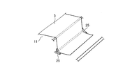
- FIG. 1 is a side view of the molding jig according to the first embodiment.
- FIG. 2 is an explanatory diagram related to the method for molding the laminate according to the first embodiment.
- FIG. 3 is an explanatory diagram showing a laminated body according to the first embodiment.
- FIG. 4 is a perspective view schematically showing a part of the molding jig according to the first embodiment.
- FIG. 5 is a side view of a molding jig according to another example of the first embodiment.
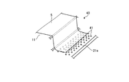
- FIG. 6 is a perspective view schematically showing a part of the molding jig according to the second embodiment.
- FIG. 7 is a perspective view schematically showing a part of the molding jig according to the third embodiment.
- the molding jig 10 is a jig used when molding the laminated body 5 in which a plurality of reinforcing fiber base materials are laminated.
- the method of forming the laminated body 5 using the forming jig 10 is a method of bending the laminated body 5 laminated in a substantially flat plate shape to form the laminated body 5 having a curved portion.
- the laminated body 5 has a Z shape including, as the curved portion, a convex curved portion that is convex with respect to the upper surface of the laminated body 5 and a concave curved portion that is concave with respect to the upper surface of the laminated body 5.
- the laminated body 5 having a shape is formed.
- any shape may be sufficient, for example, one curved part is formed. It may have an L-shape, and a U-shape in which two curved portions that curve in the same direction are formed.
- FIG. 1 is a side view of the molding jig according to the first embodiment.
- FIG. 2 is an explanatory diagram related to the method for molding the laminate according to the first embodiment.
- FIG. 3 is an explanatory diagram showing a laminated body according to the first embodiment.
- FIG. 4 is a perspective view schematically showing a part of the molding jig according to the first embodiment.
- the laminated body 5 is formed by laminating a plurality of dry reinforcing fiber base materials not impregnated with a resin.
- the reinforcing fiber base material 6 is a base material formed into a sheet shape.
- the reinforcing fiber for example, carbon fiber is used, but it is not limited to carbon fiber, and other plastic fiber, glass fiber, natural fiber or metal fiber may be used.
- the reinforced fiber base material in a dry state is applied in the first embodiment, a prepreg as a reinforced fiber base material impregnated with a resin may be applied.
- the laminated body 5 is formed by laminating the reinforcing fiber base material on the forming surface 21 and the supporting surface 22 of the forming jig 10.
- the laminated body 5 after lamination and before deformation has a shape following the molding surface 21 and the support surface 22, and has a substantially flat plate shape.
- the substantially flat plate shape is, for example, a flat plate shape having a flat surface, an arc shape having a gentle curved surface, or the like.
- the deformed laminated body 5 has a Z shape, and specifically, the first laminated portion 5a, the convex curved portion 5b, the second laminated portion 5c, the concave curved portion 5d, and the third laminated portion. And part 5e.
- the first laminated portion 5a is a portion that is fixed when the laminated body 5 is deformed, and is a portion that is not deformed before and after the laminated body 5 is deformed. Therefore, the first laminated portion 5a has a substantially flat plate shape.
- the first laminated portion 5a is a portion on one side of the laminated body 5 (on the left side in FIG. 1), and is a portion that occupies more than half of the laminated body 5.
- the convex curved portion 5b is a portion formed between the first laminated portion 5a and the second laminated portion 5c.
- the convex curved portion 5b is a portion that is deformed when the laminated body 5 is deformed, and is a curved portion that protrudes (becomes convex) outward with respect to the molding surface 21 of the molding jig 10 described later.
- the second laminated portion 5c is a portion extending in a direction intersecting (substantially orthogonal to) the first laminated portion 5a, and is located between the first laminated portion 5a and the third laminated portion 5e. There is.
- the second laminated portion 5c is a portion where interlayer slip occurs when the laminated body 5 is deformed.
- the concave curved portion 5d is a portion formed between the second laminated portion 5c and the third laminated portion 5e.
- the concave curved portion 5d is a portion that is deformed when the laminated body 5 is deformed, and is a portion that is concave (concave) inward with respect to the molding surface 21 of the molding jig 10 described later.
- the third laminated portion 5e is a portion on the other side (right side in FIG. 1) of the laminated body 5.
- the third laminated portion 5e is a portion where interlayer slip occurs when the laminated body 5 is deformed.
- the third laminated portion 5e is substantially parallel to the first laminated portion 5a.
- the molding jig 10 for molding the laminated body 5 will be described with reference to FIG.
- the forming jig 10 is used to form the substantially flat plate-shaped laminated body 5 before being deformed, and deforms the substantially flat plate-shaped laminated body 5 to have a convex curved portion 5b and a concave curved portion 5d. It is used to form a Z-shaped stack 5.
- the molding jig 10 includes a molding jig body 11, a support jig 12, a pulling jig 13, a clasp (fixing jig) 14, a connecting band 15, a triangular mold material (mold material) 16, and a bladder bag. (Pressurizing unit) 17.
- the molding jig body 11 has a shape in which a central portion projects upward and both end portions are located downward with respect to the central portion in a horizontal plane.
- the molding jig body 11 has a molding surface 21 on the upper surfaces of the central portion and the other end portion (right side in FIG. 1).
- the forming jig main body 11 deforms the laminated body 5 along the forming surface 21 to form the laminated body 5 into a Z-shape.
- the molding surface 21 is a molding surface having a step, and includes a first molding surface 21a, a convex curved surface 21b, a second molding surface 21c, a concave curved surface 21d, and a third molding surface 21e. ..
- the first molding surface 21a is a molding surface that fixes the laminated body 5 when the laminated body 5 is deformed, and is formed at the center of the molding jig body 11.
- the first molding surface 21a is located vertically above the third molding surface 21e.
- the first molding surface 21a is a flat surface in the horizontal direction.
- the first molding surface 21a is not limited to a flat surface and may be an inclined surface or a curved surface.
- the convex curved surface 21b is a curved surface that is formed between the first molding surface 21a and the second molding surface 21c and that projects outward (convex) with respect to the molding surface 21.
- the convex curved surface 21b is a surface that forms the convex curved portion 5b with respect to the stacked body 5.
- the second molding surface 21c is a wall surface along the vertical direction, and is located between the first molding surface 21a and the third molding surface 21e in the horizontal direction (the horizontal direction in FIG. 1).
- the concave curved surface 21d is a curved surface that is formed between the second molding surface 21c and the third molding surface 21e and that is concave (concave) inward with respect to the molding surface 21.
- the concave curved surface 21d is a surface that forms the concave curved portion 5d with respect to the stacked body 5.
- the third molding surface 21e is formed on the other side (right side in FIG. 1) of the molding jig body 11.
- the third molding surface 21e is located on the lower side in the vertical direction as compared with the first molding surface 21a.
- the molding jig body 11 becomes the Z-shaped laminated body 5 in which the convex curved portion 5b and the concave curved portion 5d are formed by molding the laminated body 5 along the molding surface 21.
- the support jig 12 is detachable from the molding jig body 11.
- the support jig 12 is a jig that is used when the reinforcing fiber bases are laminated to form the laminate 5, and is removed when the laminate 5 is deformed.
- the upper surface of the support jig 12 is a support surface 22.
- the support surface 22 is a surface that is an extension of the first molding surface 21 a, and the laminated body 5 is laminated on the first molding surface 21 a of the molding jig body 11 and the support surface 22 of the supporting jig 12. It
- the support jig 12 is arranged on the third molding surface 21e of the molding jig body 11.
- the support jig 12 has a surface having a shape complementary to the surface extending from the second molding surface 21c through the concave curved surface 21d to the third molding surface 21e.
- the support jig 12 is arranged in contact with the second molding surface 21c, the concave curved surface 21d, and the third molding surface 21e of the molding jig body 11 without any gap, and thus is positioned in a predetermined position. Will be placed.
- the pulling jig 13 is attached to the end of the third stacking portion 5e of the stack 5 to apply tension to the stack 5. That is, one end of the pulling jig 13 is attached to the end of the third stacking portion 5e of the stacked body 5, and the other end is attached to the forming jig body 11. Therefore, the pulling jig 13 connects the laminated body 5 and the molding jig body 11.
- the pulling jig 13 has elasticity at the environmental temperature in the deformation step of the molding method described later, but plastically deforms at the heating temperature in the densification step. That is, the pulling jig 13 applies tension to the laminated body 5 in the deforming step. On the other hand, since the tension jig 13 is plastically deformed in the densification step, the tension applied to the laminated body 5 is reduced as compared with that in the deformation step.
- the clasp 14 fixes the laminated body 5 to the molding jig body 11.
- the clasp 14 is fixed to the molding jig body 11 with the laminated body 5 interposed therebetween.
- the clasp 14 has a head portion and a shaft portion, penetrates the shaft portion into the first stacking portion 5 a of the stacked body 5, and the shaft portion is on the first molding surface 21 a of the molding jig body 11.
- the laminated body 5 is sandwiched and fastened and fixed.
- the connection band 15 is a member that connects the clasp 14 and the triangular member 16.
- the connecting band 15 has a length such that the clasp 14 and the triangular member 16 have a predetermined positional relationship.
- the connecting band 15 has a length such that the triangular member 16 is located at a position facing the concave curved surface 21d of the molding jig body 11. Therefore, the connecting band 15 functions as a positioning member that positions the triangular member 16 with respect to the concave curved surface 21d.
- the triangular mold member 16 is a mold member that presses the laminated body 5 against the concave curved surface 21d of the molding jig body 11.
- the triangular member 16 has a triangular cross section in a side view.
- the triangular shaped member 16 includes a first facing surface 16a facing the second molding surface 21c of the molding jig body 11, a curved facing surface 16b facing the concave curved surface 21d, and a second facing surface facing the third molding surface 21e. And a surface 16c.
- the curved facing surface 16b has a smaller radius of curvature than the concave curved surface 21d. That is, the curved facing surface 16b is steeper than the concave curved surface 21d.
- a pair of spacers 25 is provided between the molding jig body 11 and the triangular member 16 on both sides in the width direction of the laminated body 5.
- the width direction of the laminated body 5 is a direction orthogonal to the direction in which the laminated body 5 is pulled by the pulling jig 13.
- the thickness of each spacer 25 is approximately the same as the thickness of the laminated body 5.
- Each spacer 25 is arranged on the concave curved surface 21 d of the molding jig body 11.
- the bladder bag 17 is a covering member that covers the laminated body 5 arranged in the molding jig body 11.
- the bladder bag 17 covers the molding jig main body 11 together with the laminated body 5 via the sealing member 26 provided on the molding surface 21 of the molding jig main body 11.
- the bladder bag 17 forms an internal space hermetically sealed by the seal member 26 between the bladder bag 17 and the molding jig body 11.
- the bladder bag 17 presses the laminated body 5 by being pressed toward the molding jig body 11 by the atmospheric pressure when the internal space is vacuumed.
- the reinforcing fiber base material is laminated in the forming jig 10 to form the laminated body 5, and the formed laminated body 5 is transformed into the Z-shaped laminated body 5.
- the forming jig 10 is in a state in which the supporting jig 12 is installed in the forming jig body 11.
- the reinforcing fiber base material is laminated on the molding surface 21 and the support surface 22 of the molding jig 10 to form the laminated body 5 (step S1: laminating step).
- the laminated body 5 is formed over the first molding surface 21a of the molding surface 21 and the support surface 22.
- the reinforcing fiber base materials are laminated so that at least a part of the layers of the reinforcing fiber base material is in a non-adhesive state.
- FIG. 3 shows a part of the laminated body 5 laminated in the laminating step S1.
- the reinforcing fiber bases are laminated while the fiber directions are different.
- the lamination is, for example, isotropic lamination, and the reinforcing fiber base material is laminated so as to be 0°, ⁇ 45°, and 90° when the predetermined fiber direction is 0°.
- the laminating step S1 in the first laminated portion 5a of the laminated body 5, the layers of the reinforcing fiber base material are bonded together in all the layers.
- the adhesion between the reinforcing fiber base materials may be performed, for example, by spraying a liquid adhesive between the layers of the reinforcing fiber base material and then by pressing, or may be pre-welded on the surface of the reinforcing fiber base material.
- the layers may be welded by heating a powdery or non-woven thermoplastic resin while pressing it, and there is no particular limitation.
- the convex curved portion 5b, the second laminated portion 5c, the concave curved portion 5d, and the third laminated portion 5e of the laminated body 5 (from the convex curved portion 5b to the third laminated portion 5e of the laminated body 5).
- at least part of the layers of the reinforcing fiber base material is in a non-adhesive state.
- the portion from the convex curved portion 5b to the third laminated portion 5e of the laminated body 5 is provided with, for example, a non-adhesive layer for every four layers.
- a layer in a non-adhesive state is provided for each predetermined layer in the portion from the convex curved portion 5b to the third laminated portion 5e of the laminated body 5, but in all layers It may be in a non-bonded state.
- step S2 the shaft portion of the clasp 14 is passed through the first stacking portion 5a of the laminated body 5, and the shaft portion of the clasp 14 is fastened to the fastening hole formed in the first molding surface 21a of the molding jig body 11.
- the laminated body 5 is clamped and fixed by being sandwiched between the head portion of the clasp 14 and the molding jig body 11.
- the triangular member 16 connected via the connecting band 15 is at a predetermined position according to the length of the connecting band 15.
- step S2 the support jig 12 is removed, and the portion of the laminated body 5 facing the support surface 22 can be moved. That is, the portion of the laminated body 5 facing the support surface 22 is the portion that moves when the laminated body 5 is deformed.
- step S3 attaching process
- one end of the pulling jig 13 is attached to the end of the third stacking portion 5e of the stacked body 5, and the other end of the pulling jig 13 is attached to the forming jig body 11.
- the pulling jig 13 applies tension to the laminated body 5.
- the mounting step S3 the molding jig body 11 is covered together with the laminated body 5 to which the pulling jig 13 is mounted.
- step S4 deformation step
- the bladder bag 17 is pressed against the molding surface 21 of the molding jig body 11.
- the bladder bag 17 presses the first laminated portion 5a of the laminated body 5.
- the convex curved portion 5b, the second laminated portion 5c, the concave curved portion 5d, and the third laminated portion 5e of the laminated body 5 are pressed by the bladder bag 17 via the triangular shaped member 16.
- the deforming step S4 since the end portion of the laminated body 5 is pulled by the pulling jig 13, interlayer slip occurs in the portion from the convex curved portion 5b of the laminated body 5 to the third laminated portion 5e. While doing so, the laminated body 5 can be curved. Then, by the deforming step S4, the laminated body 5 becomes the Z-shaped laminated body 5 having the convex curved portion 5b and the concave curved portion 5d.
- the curved laminated body 5 is housed together with the molding jig 10 in the furnace of the heating furnace 28 such as an oven or an autoclave.
- the laminated body 5 is densified by being heated while being pressurized in the heating furnace 28 (step S5: densification step).
- step S5 densification step
- the pulling jig 13 is plastically deformed by being heated to a predetermined heating temperature. Therefore, in the densification step S5, the tensile load applied to the laminated body 5 by the tension jig 13 is reduced.
- the end portion of the laminated body 5 is pulled, and when the laminated body 5 is curved, the reinforcing fiber base material in the convex curved portion 5b and the concave curved portion 5d. It can be deformed while sliding between the layers. Therefore, in the convex curved portion 5b and the concave curved portion 5d of the laminated body 5, the occurrence of molding defects such as thickening and wrinkle can be suppressed.
- the concave curved portion 5d by forming the concave curved portion 5d by using the triangular shaped member 16, it is possible to suppress the occurrence of molding defects such as a bulge in the concave curved portion 5d, and the convex curved portion 5b and the concave curved portion 5d. It is possible to mold the Z-shaped laminated body 5 in which the portion 5d is formed.
- the tension can be appropriately applied to the laminated body 5 by the pulling jig 13 at the time of the deforming step S4.
- the densification step S5 the tensile jig 13 is plastically deformed, so that the tension applied to the laminated body 5 can be relaxed. Therefore, the laminated body 5 is made to follow the convex curved surface 21b and the concave curved surface 21d. It can be densified by appropriately pressurizing in the state.
- the laminated body 5 it is possible to bend the laminated body 5 while fixing a part of the laminated body 5 to the molding jig main body 11 with the clasp 14. For this reason, since the clasp 14 can bear the reaction force against the tension applied to the laminated body 5, the laminated body 5 grounded to the molding jig 10 does not shift and the convex shape is formed at an appropriate position of the laminated body 5.
- the curved portion 5b and the concave curved portion 5d can be formed.
- the support jig 12 when the laminated body 5 is formed, the support jig 12 is attached to the forming jig body 11 to form the laminated body 5 on the forming surface 21 and the supporting surface 22. You can Further, when the laminated body 5 is curved, the support jig 12 is removed from the molding jig main body 11 and the portion of the laminated body 5 facing the support surface 22 is moved to form a convex curved portion on the laminated body 5. 5b and the concave curved portion 5d can be formed.
- the position of the triangular member 16 with respect to the concave curved surface 21d can be set to an appropriate position, so that the stacked layers are formed.
- the concave curved portion 5d formed on the body 5 can be formed at an appropriate position.
- the laminated body 5 can be curved while fixing the first laminated portion 5a of the laminated body 5 to the molding jig body 11 by the clasp 14, the laminated body 5 can be appropriately bent.
- the convex curved portion 5b and the concave curved portion 5d can be formed at the positions.
- the description has been given by applying it to the reinforced fiber base material in the dry state.
- the prepreg as the reinforced fiber base material
- the deforming step S4 by heating the laminated body in which the prepregs are laminated, It is preferable that the layers are not bonded and are deformed.
- the laminated body 5 is fixed to the molding jig main body 11 by using the clasp 14, but it may be fixed as shown in FIG. 5, for example.
- the laminated body 5 is provided with the portions from the convex curved portion 5b to the third laminated portion 5e at both ends of the first laminated portion 5a.
- the laminate 5 is fixed to the forming jig body 11 by applying tension from the pulling jigs 13 from both sides of the laminate 5.
- the molding jig body 11 shown in FIG. 5 has the configuration on the other side (right side in FIG. 1) of the molding jig body 11 shown in FIG. 1 expanded to one side (left side in FIG. 1) with the central portion sandwiched therebetween. It is composed. Further, in FIG. 5, the clasp 14 may be omitted.
- the laminated body 5 is formed on the molding surface 21 and the support surface 22 of the molding jig 10.
- the laminated body 5 may be deformed.
- the molding jig 10 may be configured without the support jig 12.
- FIG. 6 is a perspective view schematically showing a part of the molding jig according to the second embodiment.
- parts different from the first embodiment will be described, and parts having the same configuration as the first embodiment will be described with the same reference numerals.
- the forming jig 30 according to the second embodiment further includes a roller 31 as a rotating body (contact friction reducing element) with which the end of the laminated body 5 comes in contact with the forming jig 10 according to the first embodiment.
- a roller 31 as a rotating body (contact friction reducing element) with which the end of the laminated body 5 comes in contact with the forming jig 10 according to the first embodiment.
- a plurality of rollers 31 are provided on the third molding surface 21e of the molding jig body 11. Each roller 31 is rotatable in the direction in which the third laminated portion 5e of the laminated body 5 moves to the concave curved surface 21d.
- the plurality of rollers 31 causes the stacked body 5 to move.
- the third laminated portion 5e slides and moves toward the concave curved surface 21d.
- the convex curved portion 5b and the concave curved portion 5b of the stacked body 5 are generated by the frictional force generated when the third stacked portion 5e of the stacked body 5 contacts the third molding surface 21e. It is possible to suppress the inhibition of the formation of the portion 5d.
- FIG. 7 is a perspective view schematically showing a part of the molding jig according to the third embodiment.
- parts different from those in the first and second embodiments will be described in order to avoid redundant description, and parts having the same configurations as those in the first and second embodiments will be described with the same reference numerals.
- the forming jig 40 according to the third embodiment further includes the forming jig 10 according to the first embodiment further including a roller ball 41 as a rotating body (contact friction reducing element) with which an end of the laminated body 5 contacts. ing.
- a plurality of roller balls 41 are provided on the third molding surface 21e of the molding jig body 11. Each roller ball 41 is rotatable in any direction.
- the plurality of roller balls 41 are used to move the stacked body 5 together.
- the third laminated portion 5e slides and moves toward the concave curved surface 21d.
- the convex curved portion 5b and the concave curved portion 5b of the laminated body 5 are generated by the frictional force generated by the contact of the third laminated portion 5e of the laminated body 5 with the third molding surface 21e. It is possible to suppress the inhibition of the formation of the portion 5d.
Landscapes
- Engineering & Computer Science (AREA)
- Mechanical Engineering (AREA)
- Chemical & Material Sciences (AREA)
- Composite Materials (AREA)
- Moulding By Coating Moulds (AREA)
- Casting Or Compression Moulding Of Plastics Or The Like (AREA)
Abstract
L'invention concerne un procédé de moulage d'un corps stratifié qui comprend les étapes suivantes : la stratification S1, qui permet de contrecoller un matériau de base de fibres de renforcement sur une surface de moulage 21 d'un dispositif de moulage 10 afin de former un corps stratifié 5 ; la fixation S3 afin de fixer un dispositif de traction 13 à une troisième partie de stratification du corps stratifié 5 ; la déformation S4 pour la formation d'une partie à courbure en saillie et d'une partie en courbure en renfoncement dans le corps stratifié 5 par incurvation du corps stratifié 5 le long d'une surface à courbure en saillie et d'une surface à courbure en renfoncement formée sur la surface de moulage 21 lors de la traction de l'extrémité du corps stratifié 5 à l'aide du dispositif de traction 13 ; la densification S5 qui permet de densifier le corps stratifié 5 par chauffage du corps stratifié incurvé 5 pendant la mise sous pression de ce dernier. Dans l'étape de stratification S1, le matériau de base de fibres de renforcement est stratifié de façon qu'au moins une partie d'un espace entre les couches du matériau de base de fibres de renforcement soit dans un état non adhérent dans une partie allant de la partie à courbure en saillie à la troisième partie de stratification formée dans le corps stratifié 5.
Priority Applications (2)
| Application Number | Priority Date | Filing Date | Title |
|---|---|---|---|
| EP19897299.4A EP3875241B1 (fr) | 2018-12-10 | 2019-10-17 | Procédé de moulage et dispositif de moulage pour corps stratifié |
| US17/312,024 US20220024159A1 (en) | 2018-12-10 | 2019-10-17 | Molding method and molding jig for laminated body |
Applications Claiming Priority (2)
| Application Number | Priority Date | Filing Date | Title |
|---|---|---|---|
| JP2018-231137 | 2018-12-10 | ||
| JP2018231137A JP7153548B2 (ja) | 2018-12-10 | 2018-12-10 | 積層体の成形方法及び成形治具 |
Publications (1)
| Publication Number | Publication Date |
|---|---|
| WO2020121648A1 true WO2020121648A1 (fr) | 2020-06-18 |
Family
ID=71077229
Family Applications (1)
| Application Number | Title | Priority Date | Filing Date |
|---|---|---|---|
| PCT/JP2019/040894 WO2020121648A1 (fr) | 2018-12-10 | 2019-10-17 | Procédé de moulage et dispositif de moulage pour corps stratifié |
Country Status (4)
| Country | Link |
|---|---|
| US (1) | US20220024159A1 (fr) |
| EP (1) | EP3875241B1 (fr) |
| JP (1) | JP7153548B2 (fr) |
| WO (1) | WO2020121648A1 (fr) |
Cited By (2)
| Publication number | Priority date | Publication date | Assignee | Title |
|---|---|---|---|---|
| IT202000028046A1 (it) * | 2020-11-23 | 2022-05-23 | Leonardo Spa | Metodo e dispositivo per la fabbricazione di un elemento strutturale in materiale composito con profilo a z |
| EP4079485A4 (fr) * | 2020-06-29 | 2023-01-11 | Mitsubishi Heavy Industries, Ltd. | Procédé et dispositif de façonnage |
Families Citing this family (2)
| Publication number | Priority date | Publication date | Assignee | Title |
|---|---|---|---|---|
| US20230271375A1 (en) * | 2020-09-01 | 2023-08-31 | Mitsubishi Heavy Industries, Ltd. | Shaping device and shaping method |
| JP2024032403A (ja) * | 2022-08-29 | 2024-03-12 | 三菱重工業株式会社 | 複合材の成形方法及び成形装置 |
Citations (4)
| Publication number | Priority date | Publication date | Assignee | Title |
|---|---|---|---|---|
| JPH0542590A (ja) * | 1991-08-12 | 1993-02-23 | Kawasaki Heavy Ind Ltd | 繊維強化複合材の成形方法 |
| JP2012121227A (ja) * | 2010-12-08 | 2012-06-28 | Mitsubishi Heavy Ind Ltd | 複合材製造方法 |
| JP2015231740A (ja) | 2014-06-04 | 2015-12-24 | ザ・ボーイング・カンパニーTheBoeing Company | 材料の層状体の表面輪郭を規定するためのシステム及び方法 |
| US20160121589A1 (en) * | 2014-10-31 | 2016-05-05 | The Boeing Company | Method and system of forming a composite laminate |
Family Cites Families (14)
| Publication number | Priority date | Publication date | Assignee | Title |
|---|---|---|---|---|
| JP2934437B1 (ja) * | 1998-08-06 | 1999-08-16 | 川崎重工業株式会社 | 繊維強化複合材の成形方法 |
| JP4867917B2 (ja) * | 2006-03-08 | 2012-02-01 | 東レ株式会社 | 強化繊維成形体の製造方法および製造装置 |
| DE102007058727A1 (de) * | 2007-12-06 | 2009-06-10 | Airbus Deutschland Gmbh | Verfahren zur Herstellung eines FVW-Vorformlings aus einem Laminat mit zumindest zwei Prepreg-Lagen sowie Herstellungsvorrichtung für ein derartiges Verfahren |
| EP2116358B1 (fr) * | 2008-05-09 | 2016-06-29 | Saab Ab | Méthode et outillage de mise en forme d'un flanc |
| JP5226470B2 (ja) * | 2008-11-13 | 2013-07-03 | 富士重工業株式会社 | 折曲成形装置 |
| DE102011100640A1 (de) * | 2011-05-05 | 2012-11-08 | Compositence Gmbh | Verfahren und Vorrichtung zum Herstellen von Fasergelegen und Bauteilvorformlingen aus Fasern |
| FR2999970B1 (fr) * | 2012-12-20 | 2015-06-19 | Airbus Operations Sas | Procede de realisation d'une preforme textile a fibres continues par circulation d'un flux de gaz chaud a travers un ensemble fibreux |
| JP6121740B2 (ja) * | 2013-02-13 | 2017-04-26 | 株式会社Ihi | ファンブレードの製造方法および製造装置 |
| US9623620B2 (en) * | 2013-12-19 | 2017-04-18 | Embraer S.A. | Three-dimensional reuseable curing caul for use in curing integrated composite components and methods of making the same |
| JP6409569B2 (ja) * | 2014-12-26 | 2018-10-24 | 東レ株式会社 | 繊維強化プラスチックの製造方法 |
| US10239251B2 (en) * | 2016-01-22 | 2019-03-26 | The Boeing Company | Apparatus and method of forming a composite structure |
| US10213968B2 (en) * | 2016-03-04 | 2019-02-26 | The Boeing Company | Dynamic forming tools for composite parts |
| GB201615213D0 (en) * | 2016-09-07 | 2016-10-19 | Univ Of Bristol The | Vacuum forming a laminate charge |
| US10875232B2 (en) * | 2017-04-04 | 2020-12-29 | The Boeing Company | Composite part and method for making composite part |
-
2018
- 2018-12-10 JP JP2018231137A patent/JP7153548B2/ja active Active
-
2019
- 2019-10-17 US US17/312,024 patent/US20220024159A1/en active Pending
- 2019-10-17 EP EP19897299.4A patent/EP3875241B1/fr active Active
- 2019-10-17 WO PCT/JP2019/040894 patent/WO2020121648A1/fr unknown
Patent Citations (4)
| Publication number | Priority date | Publication date | Assignee | Title |
|---|---|---|---|---|
| JPH0542590A (ja) * | 1991-08-12 | 1993-02-23 | Kawasaki Heavy Ind Ltd | 繊維強化複合材の成形方法 |
| JP2012121227A (ja) * | 2010-12-08 | 2012-06-28 | Mitsubishi Heavy Ind Ltd | 複合材製造方法 |
| JP2015231740A (ja) | 2014-06-04 | 2015-12-24 | ザ・ボーイング・カンパニーTheBoeing Company | 材料の層状体の表面輪郭を規定するためのシステム及び方法 |
| US20160121589A1 (en) * | 2014-10-31 | 2016-05-05 | The Boeing Company | Method and system of forming a composite laminate |
Non-Patent Citations (1)
| Title |
|---|
| See also references of EP3875241A4 |
Cited By (3)
| Publication number | Priority date | Publication date | Assignee | Title |
|---|---|---|---|---|
| EP4079485A4 (fr) * | 2020-06-29 | 2023-01-11 | Mitsubishi Heavy Industries, Ltd. | Procédé et dispositif de façonnage |
| IT202000028046A1 (it) * | 2020-11-23 | 2022-05-23 | Leonardo Spa | Metodo e dispositivo per la fabbricazione di un elemento strutturale in materiale composito con profilo a z |
| WO2022107109A1 (fr) * | 2020-11-23 | 2022-05-27 | Leonardo S.P.A. | Procédé et dispositif de fabrication d'un élément structural en matériau composite à profil en forme de z |
Also Published As
| Publication number | Publication date |
|---|---|
| US20220024159A1 (en) | 2022-01-27 |
| EP3875241B1 (fr) | 2023-03-22 |
| JP2020093416A (ja) | 2020-06-18 |
| EP3875241A1 (fr) | 2021-09-08 |
| JP7153548B2 (ja) | 2022-10-14 |
| EP3875241A4 (fr) | 2021-12-15 |
Similar Documents
| Publication | Publication Date | Title |
|---|---|---|
| WO2020121648A1 (fr) | Procédé de moulage et dispositif de moulage pour corps stratifié | |
| JP4191343B2 (ja) | ハニカムサンドイッチパネルの製造方法 | |
| JP5476916B2 (ja) | 繊維強化プラスチックの製造方法 | |
| US10583642B2 (en) | Honeycomb structural body and method of manufacturing honeycomb structural body | |
| JP4328579B2 (ja) | ハニカムサンドイッチパネルの製造方法 | |
| WO2022049618A1 (fr) | Dispositif de mise en forme et méthode de mise en forme | |
| JP4354463B2 (ja) | 複合材を用いた構造部材の成形方法及び複合材料を用いた構造部材 | |
| JP3822182B2 (ja) | 複合材料ハニカムサンドイッチ構造の製造方法 | |
| US20200180240A1 (en) | Method and device for consolidating a composite fiber structure | |
| JP2005288785A (ja) | プリフォームの製造方法 | |
| US11945179B2 (en) | Method and device for molding laminate | |
| JP3204529B2 (ja) | 曲面ハニカムパネルの製造方法 | |
| WO2015008536A1 (fr) | Matériau composite moulé renforcé de fibres, son procédé de production, et matériau pour panneau | |
| JP3004309B2 (ja) | 繊維強化樹脂積層体の製造方法 | |
| JP2014091271A (ja) | 部品加圧装置および方法 | |
| US20210402674A1 (en) | Composite material and method of forming composite material | |
| JP7255025B2 (ja) | 治具及び複合材の加工方法 | |
| JP7225320B2 (ja) | 賦形方法および賦形装置 | |
| WO2024048125A1 (fr) | Procédé et dispositif de moulage d'un matériau composite | |
| JP3493131B2 (ja) | バイセクトタイプの繊維強化プラスチック製のハニカムコアの製造方法 | |
| JPH10278185A (ja) | サンドイッチ構造体の製造方法 | |
| JP2024032403A (ja) | 複合材の成形方法及び成形装置 | |
| US20220055281A1 (en) | Laminate shaping apparatus and laminate shaping method | |
| JP2022113387A (ja) | 成形装置及び成形方法 | |
| EP3052287B1 (fr) | Outillage souple |
Legal Events
| Date | Code | Title | Description |
|---|---|---|---|
| 121 | Ep: the epo has been informed by wipo that ep was designated in this application |
Ref document number: 19897299 Country of ref document: EP Kind code of ref document: A1 |
|
| ENP | Entry into the national phase |
Ref document number: 2019897299 Country of ref document: EP Effective date: 20210602 |
|
| NENP | Non-entry into the national phase |
Ref country code: DE |