WO2020121648A1 - Molding method and molding jig for laminated body - Google Patents
Molding method and molding jig for laminated body Download PDFInfo
- Publication number
- WO2020121648A1 WO2020121648A1 PCT/JP2019/040894 JP2019040894W WO2020121648A1 WO 2020121648 A1 WO2020121648 A1 WO 2020121648A1 JP 2019040894 W JP2019040894 W JP 2019040894W WO 2020121648 A1 WO2020121648 A1 WO 2020121648A1
- Authority
- WO
- WIPO (PCT)
- Prior art keywords
- laminated body
- molding
- jig
- laminated
- laminate
- Prior art date
Links
Images


Classifications
-
- B—PERFORMING OPERATIONS; TRANSPORTING
- B29—WORKING OF PLASTICS; WORKING OF SUBSTANCES IN A PLASTIC STATE IN GENERAL
- B29C—SHAPING OR JOINING OF PLASTICS; SHAPING OF MATERIAL IN A PLASTIC STATE, NOT OTHERWISE PROVIDED FOR; AFTER-TREATMENT OF THE SHAPED PRODUCTS, e.g. REPAIRING
- B29C70/00—Shaping composites, i.e. plastics material comprising reinforcements, fillers or preformed parts, e.g. inserts
- B29C70/04—Shaping composites, i.e. plastics material comprising reinforcements, fillers or preformed parts, e.g. inserts comprising reinforcements only, e.g. self-reinforcing plastics
- B29C70/28—Shaping operations therefor
- B29C70/54—Component parts, details or accessories; Auxiliary operations, e.g. feeding or storage of prepregs or SMC after impregnation or during ageing
-
- B—PERFORMING OPERATIONS; TRANSPORTING
- B29—WORKING OF PLASTICS; WORKING OF SUBSTANCES IN A PLASTIC STATE IN GENERAL
- B29C—SHAPING OR JOINING OF PLASTICS; SHAPING OF MATERIAL IN A PLASTIC STATE, NOT OTHERWISE PROVIDED FOR; AFTER-TREATMENT OF THE SHAPED PRODUCTS, e.g. REPAIRING
- B29C43/00—Compression moulding, i.e. applying external pressure to flow the moulding material; Apparatus therefor
- B29C43/02—Compression moulding, i.e. applying external pressure to flow the moulding material; Apparatus therefor of articles of definite length, i.e. discrete articles
- B29C43/10—Isostatic pressing, i.e. using non-rigid pressure-exerting members against rigid parts or dies
- B29C43/12—Isostatic pressing, i.e. using non-rigid pressure-exerting members against rigid parts or dies using bags surrounding the moulding material or using membranes contacting the moulding material
-
- B—PERFORMING OPERATIONS; TRANSPORTING
- B29—WORKING OF PLASTICS; WORKING OF SUBSTANCES IN A PLASTIC STATE IN GENERAL
- B29C—SHAPING OR JOINING OF PLASTICS; SHAPING OF MATERIAL IN A PLASTIC STATE, NOT OTHERWISE PROVIDED FOR; AFTER-TREATMENT OF THE SHAPED PRODUCTS, e.g. REPAIRING
- B29C43/00—Compression moulding, i.e. applying external pressure to flow the moulding material; Apparatus therefor
- B29C43/32—Component parts, details or accessories; Auxiliary operations
- B29C43/36—Moulds for making articles of definite length, i.e. discrete articles
- B29C43/3642—Bags, bleeder sheets or cauls for isostatic pressing
-
- B—PERFORMING OPERATIONS; TRANSPORTING
- B29—WORKING OF PLASTICS; WORKING OF SUBSTANCES IN A PLASTIC STATE IN GENERAL
- B29C—SHAPING OR JOINING OF PLASTICS; SHAPING OF MATERIAL IN A PLASTIC STATE, NOT OTHERWISE PROVIDED FOR; AFTER-TREATMENT OF THE SHAPED PRODUCTS, e.g. REPAIRING
- B29C70/00—Shaping composites, i.e. plastics material comprising reinforcements, fillers or preformed parts, e.g. inserts
- B29C70/04—Shaping composites, i.e. plastics material comprising reinforcements, fillers or preformed parts, e.g. inserts comprising reinforcements only, e.g. self-reinforcing plastics
- B29C70/28—Shaping operations therefor
- B29C70/40—Shaping or impregnating by compression not applied
- B29C70/42—Shaping or impregnating by compression not applied for producing articles of definite length, i.e. discrete articles
- B29C70/44—Shaping or impregnating by compression not applied for producing articles of definite length, i.e. discrete articles using isostatic pressure, e.g. pressure difference-moulding, vacuum bag-moulding, autoclave-moulding or expanding rubber-moulding
- B29C70/446—Moulding structures having an axis of symmetry or at least one channel, e.g. tubular structures, frames
-
- B—PERFORMING OPERATIONS; TRANSPORTING
- B29—WORKING OF PLASTICS; WORKING OF SUBSTANCES IN A PLASTIC STATE IN GENERAL
- B29C—SHAPING OR JOINING OF PLASTICS; SHAPING OF MATERIAL IN A PLASTIC STATE, NOT OTHERWISE PROVIDED FOR; AFTER-TREATMENT OF THE SHAPED PRODUCTS, e.g. REPAIRING
- B29C70/00—Shaping composites, i.e. plastics material comprising reinforcements, fillers or preformed parts, e.g. inserts
- B29C70/04—Shaping composites, i.e. plastics material comprising reinforcements, fillers or preformed parts, e.g. inserts comprising reinforcements only, e.g. self-reinforcing plastics
- B29C70/28—Shaping operations therefor
- B29C70/54—Component parts, details or accessories; Auxiliary operations, e.g. feeding or storage of prepregs or SMC after impregnation or during ageing
- B29C70/541—Positioning reinforcements in a mould, e.g. using clamping means for the reinforcement
-
- B—PERFORMING OPERATIONS; TRANSPORTING
- B29—WORKING OF PLASTICS; WORKING OF SUBSTANCES IN A PLASTIC STATE IN GENERAL
- B29C—SHAPING OR JOINING OF PLASTICS; SHAPING OF MATERIAL IN A PLASTIC STATE, NOT OTHERWISE PROVIDED FOR; AFTER-TREATMENT OF THE SHAPED PRODUCTS, e.g. REPAIRING
- B29C70/00—Shaping composites, i.e. plastics material comprising reinforcements, fillers or preformed parts, e.g. inserts
- B29C70/04—Shaping composites, i.e. plastics material comprising reinforcements, fillers or preformed parts, e.g. inserts comprising reinforcements only, e.g. self-reinforcing plastics
- B29C70/28—Shaping operations therefor
- B29C70/54—Component parts, details or accessories; Auxiliary operations, e.g. feeding or storage of prepregs or SMC after impregnation or during ageing
- B29C70/56—Tensioning reinforcements before or during shaping
-
- B—PERFORMING OPERATIONS; TRANSPORTING
- B29—WORKING OF PLASTICS; WORKING OF SUBSTANCES IN A PLASTIC STATE IN GENERAL
- B29C—SHAPING OR JOINING OF PLASTICS; SHAPING OF MATERIAL IN A PLASTIC STATE, NOT OTHERWISE PROVIDED FOR; AFTER-TREATMENT OF THE SHAPED PRODUCTS, e.g. REPAIRING
- B29C43/00—Compression moulding, i.e. applying external pressure to flow the moulding material; Apparatus therefor
- B29C43/32—Component parts, details or accessories; Auxiliary operations
- B29C43/36—Moulds for making articles of definite length, i.e. discrete articles
- B29C2043/3602—Moulds for making articles of definite length, i.e. discrete articles with means for positioning, fastening or clamping the material to be formed or preforms inside the mould
-
- B—PERFORMING OPERATIONS; TRANSPORTING
- B29—WORKING OF PLASTICS; WORKING OF SUBSTANCES IN A PLASTIC STATE IN GENERAL
- B29C—SHAPING OR JOINING OF PLASTICS; SHAPING OF MATERIAL IN A PLASTIC STATE, NOT OTHERWISE PROVIDED FOR; AFTER-TREATMENT OF THE SHAPED PRODUCTS, e.g. REPAIRING
- B29C43/00—Compression moulding, i.e. applying external pressure to flow the moulding material; Apparatus therefor
- B29C43/32—Component parts, details or accessories; Auxiliary operations
- B29C43/36—Moulds for making articles of definite length, i.e. discrete articles
- B29C43/3642—Bags, bleeder sheets or cauls for isostatic pressing
- B29C2043/3655—Pressure transmitters, e.g. caul plates; pressure pads
-
- B—PERFORMING OPERATIONS; TRANSPORTING
- B29—WORKING OF PLASTICS; WORKING OF SUBSTANCES IN A PLASTIC STATE IN GENERAL
- B29C—SHAPING OR JOINING OF PLASTICS; SHAPING OF MATERIAL IN A PLASTIC STATE, NOT OTHERWISE PROVIDED FOR; AFTER-TREATMENT OF THE SHAPED PRODUCTS, e.g. REPAIRING
- B29C43/00—Compression moulding, i.e. applying external pressure to flow the moulding material; Apparatus therefor
- B29C43/32—Component parts, details or accessories; Auxiliary operations
- B29C43/36—Moulds for making articles of definite length, i.e. discrete articles
- B29C43/3642—Bags, bleeder sheets or cauls for isostatic pressing
- B29C2043/3657—Bags, bleeder sheets or cauls for isostatic pressing additional materials, e.g. permeable bleeder or breather sheets, cloths, blankets
-
- B—PERFORMING OPERATIONS; TRANSPORTING
- B29—WORKING OF PLASTICS; WORKING OF SUBSTANCES IN A PLASTIC STATE IN GENERAL
- B29C—SHAPING OR JOINING OF PLASTICS; SHAPING OF MATERIAL IN A PLASTIC STATE, NOT OTHERWISE PROVIDED FOR; AFTER-TREATMENT OF THE SHAPED PRODUCTS, e.g. REPAIRING
- B29C43/00—Compression moulding, i.e. applying external pressure to flow the moulding material; Apparatus therefor
- B29C43/32—Component parts, details or accessories; Auxiliary operations
- B29C43/52—Heating or cooling
-
- B—PERFORMING OPERATIONS; TRANSPORTING
- B29—WORKING OF PLASTICS; WORKING OF SUBSTANCES IN A PLASTIC STATE IN GENERAL
- B29K—INDEXING SCHEME ASSOCIATED WITH SUBCLASSES B29B, B29C OR B29D, RELATING TO MOULDING MATERIALS OR TO MATERIALS FOR MOULDS, REINFORCEMENTS, FILLERS OR PREFORMED PARTS, e.g. INSERTS
- B29K2105/00—Condition, form or state of moulded material or of the material to be shaped
- B29K2105/06—Condition, form or state of moulded material or of the material to be shaped containing reinforcements, fillers or inserts
- B29K2105/08—Condition, form or state of moulded material or of the material to be shaped containing reinforcements, fillers or inserts of continuous length, e.g. cords, rovings, mats, fabrics, strands or yarns
Definitions
- the present invention relates to a method for molding a laminate and a molding jig.
- a molding system and method for deforming a layered body from an initial form to a final form to define the surface contour of the layered body are known (for example, refer to Patent Document 1).
- this forming system and method buckling and wrinkles that occur when the layered body is deformed are suppressed.
- the layered body is disposed on the molding surface of the molding die and the support surface of the fluid actuated support. The molding system and method then compresses the fluid actuated support and translates the support surface relative to the molding surface to deform the layered body and define a desired surface contour.
- the curved portion has a ridge (thickening) or a meandering fiber. Molding failure such as (wrinkle) may occur.
- the molding system and method of Patent Document 1 suppress buckling and wrinkles that occur when the layered body is deformed, molding failure may occur in the curved portion.
- an object of the present invention is to provide a molding method and a molding jig for a laminated body that can suppress the occurrence of molding defects and can appropriately deform into a shape having a curved portion.
- the method for forming a laminated body of the present invention comprises a laminating step of laminating a reinforcing fiber base material on the forming surface of a forming jig to form a laminated body, and a pulling jig for applying tension to the end portion of the laminated body.
- a densification step of densifying the laminated body by heating the curved laminated body while pressurizing the curved laminated body.
- the reinforcing fiber base materials are laminated so that at least a part of the layers of the reinforcing fiber base material is in a non-adhesive state in the deforming step.
- the end portion of the laminated body in the deforming step, can be pulled, and when the laminated body is curved, the laminated body can be deformed while sliding between the layers of the reinforcing fiber base material in the curved portion. It is possible to suppress the occurrence of molding defects such as thickening and wrinkle in the portion.
- the shape of the laminated body having the curved portion for example, an L-shaped shape in which one curved portion is formed, a Z-shaped shape in which a curved portion that curves in two different directions is formed, and two in the same direction There is a U-shape or the like in which a curved curved portion is formed.
- all the layers of the reinforcing fiber base material in the curved portion may be in a non-adhesive state, or may be in a non-adhesive state for each predetermined layer, and there is no particular limitation.
- all the layers of the reinforcing fiber base material other than the curved portion may be in an adhesive state, or may be in a non-adhesive state for each predetermined layer, and there is no particular limitation.
- the molding surface includes, as the curved surface, a convex curved surface that is convex outside the molding surface and a concave curved surface that is concave inside the molding surface, and in the deforming step, the tension By bending the laminate along the convex curved surface while pulling the end portion of the laminate with the jig, a convex curved portion is formed in the laminate, and the tension jig is used to form the convex curved portion. It is preferable that the concave curved portion is formed in the laminated body by pressing the laminated body against the concave curved surface using the mold material while pulling the end portion of the laminated body.
- the pulling jig has elasticity at the environmental temperature in the deforming step and plastically deforms at the heating temperature in the densifying step.
- the tension of the laminated body can be relaxed by plastically deforming the tension jig, so that it is possible to appropriately press and densify the laminated body in a state of following the curved surface. it can.
- the laminated body is fixed to the forming jig by a fixing portion that fixes an end portion opposite to an end portion that pulls the laminated body by the pulling jig.
- the fixed portion can bear the reaction force against the tension applied to the laminated body
- the curved portion can be formed in the laminated body without shifting the laminated body grounded to the molding jig. ..
- the fixing portion is a fixing jig that fixes the laminated body to the molding jig, or a pulling jig that is attached to the opposite end of the laminated body.
- the end of the laminate is slid by providing a contact friction reducing element provided on the molding surface with which the end of the laminate comes into contact.
- the contact friction reducing element is a rotating body or the like.
- the molding jig of the present invention includes a molding jig body having a molding surface, a pulling jig that is attached to an end portion of a laminated body arranged on the molding surface, and applies tension to the laminated body, A pressurizing portion that presses the body toward the forming surface, the forming surface including a curved surface for forming a curved portion in the laminate.
- the laminated body while pulling the end portion of the laminated body with the pulling jig, the laminated body is curved along the curved surface, thereby suppressing occurrence of molding defects such as thickening and wrinkle, and
- the curved portion can be preferably formed.
- a supporting jig having a supporting surface for supporting an end portion of the laminated body arranged on the molding surface is further provided, and the supporting jig is detachably provided to the molding jig body. It is preferable that
- the supporting jig when forming a laminated body, can be attached to the forming jig body to form the laminated body on the forming surface and the supporting surface. Further, when the laminated body is curved, the supporting jig can be removed from the forming jig main body, and the portion of the laminated body facing the support surface can be moved to form the curved portion in the laminated body.
- the molding surface includes, as the curved surface, a convex curved surface that is convex outside the molding surface, and a concave curved surface that is concave inside the molding surface, with respect to the concave curved surface. It is preferable to further include a mold member for pressing the laminated body.
- a positioning member for positioning the mold material with respect to the concave curved surface.
- the concave curved portion formed on the laminated body can be formed at an appropriate position.
- a fixing jig for fixing a part of the laminate to the molding jig body is further provided.
- the laminated body can be curved while fixing a part of the laminated body to the forming jig main body by the fixing jig, the curved portion can be formed at an appropriate position of the laminated body. ..
- a contact friction reducing element provided on the molding surface with which the end of the laminate comes into contact.
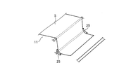
- FIG. 1 is a side view of the molding jig according to the first embodiment.
- FIG. 2 is an explanatory diagram related to the method for molding the laminate according to the first embodiment.
- FIG. 3 is an explanatory diagram showing a laminated body according to the first embodiment.
- FIG. 4 is a perspective view schematically showing a part of the molding jig according to the first embodiment.
- FIG. 5 is a side view of a molding jig according to another example of the first embodiment.
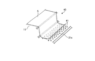
- FIG. 6 is a perspective view schematically showing a part of the molding jig according to the second embodiment.
- FIG. 7 is a perspective view schematically showing a part of the molding jig according to the third embodiment.
- the molding jig 10 is a jig used when molding the laminated body 5 in which a plurality of reinforcing fiber base materials are laminated.
- the method of forming the laminated body 5 using the forming jig 10 is a method of bending the laminated body 5 laminated in a substantially flat plate shape to form the laminated body 5 having a curved portion.
- the laminated body 5 has a Z shape including, as the curved portion, a convex curved portion that is convex with respect to the upper surface of the laminated body 5 and a concave curved portion that is concave with respect to the upper surface of the laminated body 5.
- the laminated body 5 having a shape is formed.
- any shape may be sufficient, for example, one curved part is formed. It may have an L-shape, and a U-shape in which two curved portions that curve in the same direction are formed.
- FIG. 1 is a side view of the molding jig according to the first embodiment.
- FIG. 2 is an explanatory diagram related to the method for molding the laminate according to the first embodiment.
- FIG. 3 is an explanatory diagram showing a laminated body according to the first embodiment.
- FIG. 4 is a perspective view schematically showing a part of the molding jig according to the first embodiment.
- the laminated body 5 is formed by laminating a plurality of dry reinforcing fiber base materials not impregnated with a resin.
- the reinforcing fiber base material 6 is a base material formed into a sheet shape.
- the reinforcing fiber for example, carbon fiber is used, but it is not limited to carbon fiber, and other plastic fiber, glass fiber, natural fiber or metal fiber may be used.
- the reinforced fiber base material in a dry state is applied in the first embodiment, a prepreg as a reinforced fiber base material impregnated with a resin may be applied.
- the laminated body 5 is formed by laminating the reinforcing fiber base material on the forming surface 21 and the supporting surface 22 of the forming jig 10.
- the laminated body 5 after lamination and before deformation has a shape following the molding surface 21 and the support surface 22, and has a substantially flat plate shape.
- the substantially flat plate shape is, for example, a flat plate shape having a flat surface, an arc shape having a gentle curved surface, or the like.
- the deformed laminated body 5 has a Z shape, and specifically, the first laminated portion 5a, the convex curved portion 5b, the second laminated portion 5c, the concave curved portion 5d, and the third laminated portion. And part 5e.
- the first laminated portion 5a is a portion that is fixed when the laminated body 5 is deformed, and is a portion that is not deformed before and after the laminated body 5 is deformed. Therefore, the first laminated portion 5a has a substantially flat plate shape.
- the first laminated portion 5a is a portion on one side of the laminated body 5 (on the left side in FIG. 1), and is a portion that occupies more than half of the laminated body 5.
- the convex curved portion 5b is a portion formed between the first laminated portion 5a and the second laminated portion 5c.
- the convex curved portion 5b is a portion that is deformed when the laminated body 5 is deformed, and is a curved portion that protrudes (becomes convex) outward with respect to the molding surface 21 of the molding jig 10 described later.
- the second laminated portion 5c is a portion extending in a direction intersecting (substantially orthogonal to) the first laminated portion 5a, and is located between the first laminated portion 5a and the third laminated portion 5e. There is.
- the second laminated portion 5c is a portion where interlayer slip occurs when the laminated body 5 is deformed.
- the concave curved portion 5d is a portion formed between the second laminated portion 5c and the third laminated portion 5e.
- the concave curved portion 5d is a portion that is deformed when the laminated body 5 is deformed, and is a portion that is concave (concave) inward with respect to the molding surface 21 of the molding jig 10 described later.
- the third laminated portion 5e is a portion on the other side (right side in FIG. 1) of the laminated body 5.
- the third laminated portion 5e is a portion where interlayer slip occurs when the laminated body 5 is deformed.
- the third laminated portion 5e is substantially parallel to the first laminated portion 5a.
- the molding jig 10 for molding the laminated body 5 will be described with reference to FIG.
- the forming jig 10 is used to form the substantially flat plate-shaped laminated body 5 before being deformed, and deforms the substantially flat plate-shaped laminated body 5 to have a convex curved portion 5b and a concave curved portion 5d. It is used to form a Z-shaped stack 5.
- the molding jig 10 includes a molding jig body 11, a support jig 12, a pulling jig 13, a clasp (fixing jig) 14, a connecting band 15, a triangular mold material (mold material) 16, and a bladder bag. (Pressurizing unit) 17.
- the molding jig body 11 has a shape in which a central portion projects upward and both end portions are located downward with respect to the central portion in a horizontal plane.
- the molding jig body 11 has a molding surface 21 on the upper surfaces of the central portion and the other end portion (right side in FIG. 1).
- the forming jig main body 11 deforms the laminated body 5 along the forming surface 21 to form the laminated body 5 into a Z-shape.
- the molding surface 21 is a molding surface having a step, and includes a first molding surface 21a, a convex curved surface 21b, a second molding surface 21c, a concave curved surface 21d, and a third molding surface 21e. ..
- the first molding surface 21a is a molding surface that fixes the laminated body 5 when the laminated body 5 is deformed, and is formed at the center of the molding jig body 11.
- the first molding surface 21a is located vertically above the third molding surface 21e.
- the first molding surface 21a is a flat surface in the horizontal direction.
- the first molding surface 21a is not limited to a flat surface and may be an inclined surface or a curved surface.
- the convex curved surface 21b is a curved surface that is formed between the first molding surface 21a and the second molding surface 21c and that projects outward (convex) with respect to the molding surface 21.
- the convex curved surface 21b is a surface that forms the convex curved portion 5b with respect to the stacked body 5.
- the second molding surface 21c is a wall surface along the vertical direction, and is located between the first molding surface 21a and the third molding surface 21e in the horizontal direction (the horizontal direction in FIG. 1).
- the concave curved surface 21d is a curved surface that is formed between the second molding surface 21c and the third molding surface 21e and that is concave (concave) inward with respect to the molding surface 21.
- the concave curved surface 21d is a surface that forms the concave curved portion 5d with respect to the stacked body 5.
- the third molding surface 21e is formed on the other side (right side in FIG. 1) of the molding jig body 11.
- the third molding surface 21e is located on the lower side in the vertical direction as compared with the first molding surface 21a.
- the molding jig body 11 becomes the Z-shaped laminated body 5 in which the convex curved portion 5b and the concave curved portion 5d are formed by molding the laminated body 5 along the molding surface 21.
- the support jig 12 is detachable from the molding jig body 11.
- the support jig 12 is a jig that is used when the reinforcing fiber bases are laminated to form the laminate 5, and is removed when the laminate 5 is deformed.
- the upper surface of the support jig 12 is a support surface 22.
- the support surface 22 is a surface that is an extension of the first molding surface 21 a, and the laminated body 5 is laminated on the first molding surface 21 a of the molding jig body 11 and the support surface 22 of the supporting jig 12. It
- the support jig 12 is arranged on the third molding surface 21e of the molding jig body 11.
- the support jig 12 has a surface having a shape complementary to the surface extending from the second molding surface 21c through the concave curved surface 21d to the third molding surface 21e.
- the support jig 12 is arranged in contact with the second molding surface 21c, the concave curved surface 21d, and the third molding surface 21e of the molding jig body 11 without any gap, and thus is positioned in a predetermined position. Will be placed.
- the pulling jig 13 is attached to the end of the third stacking portion 5e of the stack 5 to apply tension to the stack 5. That is, one end of the pulling jig 13 is attached to the end of the third stacking portion 5e of the stacked body 5, and the other end is attached to the forming jig body 11. Therefore, the pulling jig 13 connects the laminated body 5 and the molding jig body 11.
- the pulling jig 13 has elasticity at the environmental temperature in the deformation step of the molding method described later, but plastically deforms at the heating temperature in the densification step. That is, the pulling jig 13 applies tension to the laminated body 5 in the deforming step. On the other hand, since the tension jig 13 is plastically deformed in the densification step, the tension applied to the laminated body 5 is reduced as compared with that in the deformation step.
- the clasp 14 fixes the laminated body 5 to the molding jig body 11.
- the clasp 14 is fixed to the molding jig body 11 with the laminated body 5 interposed therebetween.
- the clasp 14 has a head portion and a shaft portion, penetrates the shaft portion into the first stacking portion 5 a of the stacked body 5, and the shaft portion is on the first molding surface 21 a of the molding jig body 11.
- the laminated body 5 is sandwiched and fastened and fixed.
- the connection band 15 is a member that connects the clasp 14 and the triangular member 16.
- the connecting band 15 has a length such that the clasp 14 and the triangular member 16 have a predetermined positional relationship.
- the connecting band 15 has a length such that the triangular member 16 is located at a position facing the concave curved surface 21d of the molding jig body 11. Therefore, the connecting band 15 functions as a positioning member that positions the triangular member 16 with respect to the concave curved surface 21d.
- the triangular mold member 16 is a mold member that presses the laminated body 5 against the concave curved surface 21d of the molding jig body 11.
- the triangular member 16 has a triangular cross section in a side view.
- the triangular shaped member 16 includes a first facing surface 16a facing the second molding surface 21c of the molding jig body 11, a curved facing surface 16b facing the concave curved surface 21d, and a second facing surface facing the third molding surface 21e. And a surface 16c.
- the curved facing surface 16b has a smaller radius of curvature than the concave curved surface 21d. That is, the curved facing surface 16b is steeper than the concave curved surface 21d.
- a pair of spacers 25 is provided between the molding jig body 11 and the triangular member 16 on both sides in the width direction of the laminated body 5.
- the width direction of the laminated body 5 is a direction orthogonal to the direction in which the laminated body 5 is pulled by the pulling jig 13.
- the thickness of each spacer 25 is approximately the same as the thickness of the laminated body 5.
- Each spacer 25 is arranged on the concave curved surface 21 d of the molding jig body 11.
- the bladder bag 17 is a covering member that covers the laminated body 5 arranged in the molding jig body 11.
- the bladder bag 17 covers the molding jig main body 11 together with the laminated body 5 via the sealing member 26 provided on the molding surface 21 of the molding jig main body 11.
- the bladder bag 17 forms an internal space hermetically sealed by the seal member 26 between the bladder bag 17 and the molding jig body 11.
- the bladder bag 17 presses the laminated body 5 by being pressed toward the molding jig body 11 by the atmospheric pressure when the internal space is vacuumed.
- the reinforcing fiber base material is laminated in the forming jig 10 to form the laminated body 5, and the formed laminated body 5 is transformed into the Z-shaped laminated body 5.
- the forming jig 10 is in a state in which the supporting jig 12 is installed in the forming jig body 11.
- the reinforcing fiber base material is laminated on the molding surface 21 and the support surface 22 of the molding jig 10 to form the laminated body 5 (step S1: laminating step).
- the laminated body 5 is formed over the first molding surface 21a of the molding surface 21 and the support surface 22.
- the reinforcing fiber base materials are laminated so that at least a part of the layers of the reinforcing fiber base material is in a non-adhesive state.
- FIG. 3 shows a part of the laminated body 5 laminated in the laminating step S1.
- the reinforcing fiber bases are laminated while the fiber directions are different.
- the lamination is, for example, isotropic lamination, and the reinforcing fiber base material is laminated so as to be 0°, ⁇ 45°, and 90° when the predetermined fiber direction is 0°.
- the laminating step S1 in the first laminated portion 5a of the laminated body 5, the layers of the reinforcing fiber base material are bonded together in all the layers.
- the adhesion between the reinforcing fiber base materials may be performed, for example, by spraying a liquid adhesive between the layers of the reinforcing fiber base material and then by pressing, or may be pre-welded on the surface of the reinforcing fiber base material.
- the layers may be welded by heating a powdery or non-woven thermoplastic resin while pressing it, and there is no particular limitation.
- the convex curved portion 5b, the second laminated portion 5c, the concave curved portion 5d, and the third laminated portion 5e of the laminated body 5 (from the convex curved portion 5b to the third laminated portion 5e of the laminated body 5).
- at least part of the layers of the reinforcing fiber base material is in a non-adhesive state.
- the portion from the convex curved portion 5b to the third laminated portion 5e of the laminated body 5 is provided with, for example, a non-adhesive layer for every four layers.
- a layer in a non-adhesive state is provided for each predetermined layer in the portion from the convex curved portion 5b to the third laminated portion 5e of the laminated body 5, but in all layers It may be in a non-bonded state.
- step S2 the shaft portion of the clasp 14 is passed through the first stacking portion 5a of the laminated body 5, and the shaft portion of the clasp 14 is fastened to the fastening hole formed in the first molding surface 21a of the molding jig body 11.
- the laminated body 5 is clamped and fixed by being sandwiched between the head portion of the clasp 14 and the molding jig body 11.
- the triangular member 16 connected via the connecting band 15 is at a predetermined position according to the length of the connecting band 15.
- step S2 the support jig 12 is removed, and the portion of the laminated body 5 facing the support surface 22 can be moved. That is, the portion of the laminated body 5 facing the support surface 22 is the portion that moves when the laminated body 5 is deformed.
- step S3 attaching process
- one end of the pulling jig 13 is attached to the end of the third stacking portion 5e of the stacked body 5, and the other end of the pulling jig 13 is attached to the forming jig body 11.
- the pulling jig 13 applies tension to the laminated body 5.
- the mounting step S3 the molding jig body 11 is covered together with the laminated body 5 to which the pulling jig 13 is mounted.
- step S4 deformation step
- the bladder bag 17 is pressed against the molding surface 21 of the molding jig body 11.
- the bladder bag 17 presses the first laminated portion 5a of the laminated body 5.
- the convex curved portion 5b, the second laminated portion 5c, the concave curved portion 5d, and the third laminated portion 5e of the laminated body 5 are pressed by the bladder bag 17 via the triangular shaped member 16.
- the deforming step S4 since the end portion of the laminated body 5 is pulled by the pulling jig 13, interlayer slip occurs in the portion from the convex curved portion 5b of the laminated body 5 to the third laminated portion 5e. While doing so, the laminated body 5 can be curved. Then, by the deforming step S4, the laminated body 5 becomes the Z-shaped laminated body 5 having the convex curved portion 5b and the concave curved portion 5d.
- the curved laminated body 5 is housed together with the molding jig 10 in the furnace of the heating furnace 28 such as an oven or an autoclave.
- the laminated body 5 is densified by being heated while being pressurized in the heating furnace 28 (step S5: densification step).
- step S5 densification step
- the pulling jig 13 is plastically deformed by being heated to a predetermined heating temperature. Therefore, in the densification step S5, the tensile load applied to the laminated body 5 by the tension jig 13 is reduced.
- the end portion of the laminated body 5 is pulled, and when the laminated body 5 is curved, the reinforcing fiber base material in the convex curved portion 5b and the concave curved portion 5d. It can be deformed while sliding between the layers. Therefore, in the convex curved portion 5b and the concave curved portion 5d of the laminated body 5, the occurrence of molding defects such as thickening and wrinkle can be suppressed.
- the concave curved portion 5d by forming the concave curved portion 5d by using the triangular shaped member 16, it is possible to suppress the occurrence of molding defects such as a bulge in the concave curved portion 5d, and the convex curved portion 5b and the concave curved portion 5d. It is possible to mold the Z-shaped laminated body 5 in which the portion 5d is formed.
- the tension can be appropriately applied to the laminated body 5 by the pulling jig 13 at the time of the deforming step S4.
- the densification step S5 the tensile jig 13 is plastically deformed, so that the tension applied to the laminated body 5 can be relaxed. Therefore, the laminated body 5 is made to follow the convex curved surface 21b and the concave curved surface 21d. It can be densified by appropriately pressurizing in the state.
- the laminated body 5 it is possible to bend the laminated body 5 while fixing a part of the laminated body 5 to the molding jig main body 11 with the clasp 14. For this reason, since the clasp 14 can bear the reaction force against the tension applied to the laminated body 5, the laminated body 5 grounded to the molding jig 10 does not shift and the convex shape is formed at an appropriate position of the laminated body 5.
- the curved portion 5b and the concave curved portion 5d can be formed.
- the support jig 12 when the laminated body 5 is formed, the support jig 12 is attached to the forming jig body 11 to form the laminated body 5 on the forming surface 21 and the supporting surface 22. You can Further, when the laminated body 5 is curved, the support jig 12 is removed from the molding jig main body 11 and the portion of the laminated body 5 facing the support surface 22 is moved to form a convex curved portion on the laminated body 5. 5b and the concave curved portion 5d can be formed.
- the position of the triangular member 16 with respect to the concave curved surface 21d can be set to an appropriate position, so that the stacked layers are formed.
- the concave curved portion 5d formed on the body 5 can be formed at an appropriate position.
- the laminated body 5 can be curved while fixing the first laminated portion 5a of the laminated body 5 to the molding jig body 11 by the clasp 14, the laminated body 5 can be appropriately bent.
- the convex curved portion 5b and the concave curved portion 5d can be formed at the positions.
- the description has been given by applying it to the reinforced fiber base material in the dry state.
- the prepreg as the reinforced fiber base material
- the deforming step S4 by heating the laminated body in which the prepregs are laminated, It is preferable that the layers are not bonded and are deformed.
- the laminated body 5 is fixed to the molding jig main body 11 by using the clasp 14, but it may be fixed as shown in FIG. 5, for example.
- the laminated body 5 is provided with the portions from the convex curved portion 5b to the third laminated portion 5e at both ends of the first laminated portion 5a.
- the laminate 5 is fixed to the forming jig body 11 by applying tension from the pulling jigs 13 from both sides of the laminate 5.
- the molding jig body 11 shown in FIG. 5 has the configuration on the other side (right side in FIG. 1) of the molding jig body 11 shown in FIG. 1 expanded to one side (left side in FIG. 1) with the central portion sandwiched therebetween. It is composed. Further, in FIG. 5, the clasp 14 may be omitted.
- the laminated body 5 is formed on the molding surface 21 and the support surface 22 of the molding jig 10.
- the laminated body 5 may be deformed.
- the molding jig 10 may be configured without the support jig 12.
- FIG. 6 is a perspective view schematically showing a part of the molding jig according to the second embodiment.
- parts different from the first embodiment will be described, and parts having the same configuration as the first embodiment will be described with the same reference numerals.
- the forming jig 30 according to the second embodiment further includes a roller 31 as a rotating body (contact friction reducing element) with which the end of the laminated body 5 comes in contact with the forming jig 10 according to the first embodiment.
- a roller 31 as a rotating body (contact friction reducing element) with which the end of the laminated body 5 comes in contact with the forming jig 10 according to the first embodiment.
- a plurality of rollers 31 are provided on the third molding surface 21e of the molding jig body 11. Each roller 31 is rotatable in the direction in which the third laminated portion 5e of the laminated body 5 moves to the concave curved surface 21d.
- the plurality of rollers 31 causes the stacked body 5 to move.
- the third laminated portion 5e slides and moves toward the concave curved surface 21d.
- the convex curved portion 5b and the concave curved portion 5b of the stacked body 5 are generated by the frictional force generated when the third stacked portion 5e of the stacked body 5 contacts the third molding surface 21e. It is possible to suppress the inhibition of the formation of the portion 5d.
- FIG. 7 is a perspective view schematically showing a part of the molding jig according to the third embodiment.
- parts different from those in the first and second embodiments will be described in order to avoid redundant description, and parts having the same configurations as those in the first and second embodiments will be described with the same reference numerals.
- the forming jig 40 according to the third embodiment further includes the forming jig 10 according to the first embodiment further including a roller ball 41 as a rotating body (contact friction reducing element) with which an end of the laminated body 5 contacts. ing.
- a plurality of roller balls 41 are provided on the third molding surface 21e of the molding jig body 11. Each roller ball 41 is rotatable in any direction.
- the plurality of roller balls 41 are used to move the stacked body 5 together.
- the third laminated portion 5e slides and moves toward the concave curved surface 21d.
- the convex curved portion 5b and the concave curved portion 5b of the laminated body 5 are generated by the frictional force generated by the contact of the third laminated portion 5e of the laminated body 5 with the third molding surface 21e. It is possible to suppress the inhibition of the formation of the portion 5d.
Abstract
This method for molding a laminated body is provided with: a lamination step S1 of laminating a reinforcing fiber base material on a molding surface 21 of a molding jig 10 to form a laminated body 5; an attachment step S3 of attaching a pulling jig 13 to a third lamination portion of the laminated body 5; a deformation step S4 of forming a protrusive curvature part and a recessed curvature part in the laminated body 5 by curving the laminated body 5 along a protrusive curvature surface and a recessed curvature surface formed on the molding surface 21 while pulling the end of the laminated body 5 with the pulling jig 13; and a densification step S5 of densifying the laminated body 5 by heating the curved laminated body 5 while pressurizing the same. In the lamination step S1, the reinforced fiber base material is laminated so that at least a part of a gap between layers of the reinforcing fiber base material becomes a non-adhered state in a portion from the protrusive curvature part to the third lamination portion formed in the laminated body 5.
Description
本発明は、積層体の成形方法及び成形治具に関するものである。
The present invention relates to a method for molding a laminate and a molding jig.
従来、層状体を初期形態から最終形態に変形させて、層状体の表面輪郭を規定する成形システム及び方法が知られている(例えば、特許文献1参照)。この成形システム及び方法では、層状体を変形する際に発生する座屈やシワを抑制している。成形システム及び方法では、層状体を、成形ダイの成形面と流体作動支持部の支持面とに配置する。そして、成形システム及び方法では、流体作動支持部を圧縮させ、成形面に対して支持面を並進させることで、層状体を変形させて所望の表面輪郭を規定している。
Conventionally, a molding system and method for deforming a layered body from an initial form to a final form to define the surface contour of the layered body are known (for example, refer to Patent Document 1). In this forming system and method, buckling and wrinkles that occur when the layered body is deformed are suppressed. In the molding system and method, the layered body is disposed on the molding surface of the molding die and the support surface of the fluid actuated support. The molding system and method then compresses the fluid actuated support and translates the support surface relative to the molding surface to deform the layered body and define a desired surface contour.
ところで、繊維強化基材を積層して形成される層状体等の積層体は、例えば、平板の形状から、湾曲部を有する形状に変形させる場合、湾曲部に、隆起(シックニング)または繊維蛇行(リンクル)等の成形不良が発生する可能性がある。特許文献1の成形システム及び方法では、層状体を変形する際に発生する座屈やシワを抑制しているものの、湾曲部において成形不良が発生する可能性がある。
By the way, when a laminated body such as a layered body formed by laminating fiber-reinforced base materials is deformed from a flat plate shape to a shape having a curved portion, the curved portion has a ridge (thickening) or a meandering fiber. Molding failure such as (wrinkle) may occur. Although the molding system and method of Patent Document 1 suppress buckling and wrinkles that occur when the layered body is deformed, molding failure may occur in the curved portion.
そこで、本発明は、成形不良の発生を抑制し、適切に湾曲部を有する形状に変形させることができる積層体の成形方法及び成形治具を提供することを課題とする。
Therefore, an object of the present invention is to provide a molding method and a molding jig for a laminated body that can suppress the occurrence of molding defects and can appropriately deform into a shape having a curved portion.
本発明の積層体の成形方法は、成形治具の成形面上に強化繊維基材を積層して積層体とする積層工程と、前記積層体の端部に、張力を付与する引張り治具を取り付ける取付工程と、前記引張り治具により前記積層体の端部を引っ張りながら、前記成形面に形成される湾曲面に沿って、前記積層体を湾曲させることにより、前記積層体に湾曲部を形成する変形工程と、湾曲させた前記積層体を加圧しながら加熱して、前記積層体を緻密化する緻密化工程と、を備え、前記積層工程では、前記積層体に形成される前記湾曲部において、前記強化繊維基材の層間の少なくとも一部が前記変形工程で非接着状態となるように、前記強化繊維基材を積層する。
The method for forming a laminated body of the present invention comprises a laminating step of laminating a reinforcing fiber base material on the forming surface of a forming jig to form a laminated body, and a pulling jig for applying tension to the end portion of the laminated body. Attaching step of attaching and bending the laminated body along the curved surface formed on the molding surface while pulling the end portion of the laminated body by the pulling jig to form a curved portion in the laminated body And a densification step of densifying the laminated body by heating the curved laminated body while pressurizing the curved laminated body. In the laminating step, in the bending portion formed in the laminated body, The reinforcing fiber base materials are laminated so that at least a part of the layers of the reinforcing fiber base material is in a non-adhesive state in the deforming step.
この構成によれば、変形工程において、積層体の端部を引っ張ると共に、積層体の湾曲時において、湾曲部における強化繊維基材の層間を滑らせながら変形させることができるため、積層体の湾曲部において、シックニング及びリンクル等の成形不良の発生を抑制することができる。なお、湾曲部を有する積層体の形状としては、例えば、1つの湾曲部が形成されたL字形状、2つの異なる向きに湾曲する湾曲部が形成されたZ字形状、及び2つの同じ向きに湾曲する湾曲部が形成されたU字形状等がある。また、積層工程において、湾曲部における強化繊維基材の層間の全てを、非接着状態としてもよいし、所定の層間毎に非接着状態としてもよく、特に限定されない。また、積層工程において、湾曲部以外における強化繊維基材の層間の全てを、接着状態としてもよいし、所定の層間毎に非接着状態としてもよく、特に限定されない。
According to this configuration, in the deforming step, the end portion of the laminated body can be pulled, and when the laminated body is curved, the laminated body can be deformed while sliding between the layers of the reinforcing fiber base material in the curved portion. It is possible to suppress the occurrence of molding defects such as thickening and wrinkle in the portion. As the shape of the laminated body having the curved portion, for example, an L-shaped shape in which one curved portion is formed, a Z-shaped shape in which a curved portion that curves in two different directions is formed, and two in the same direction There is a U-shape or the like in which a curved curved portion is formed. Further, in the laminating step, all the layers of the reinforcing fiber base material in the curved portion may be in a non-adhesive state, or may be in a non-adhesive state for each predetermined layer, and there is no particular limitation. Further, in the laminating step, all the layers of the reinforcing fiber base material other than the curved portion may be in an adhesive state, or may be in a non-adhesive state for each predetermined layer, and there is no particular limitation.
また、前記成形面は、前記湾曲面として、前記成形面の外側に凸となる凸状湾曲面と、前記成形面の内側に凹となる凹状湾曲面とを含み、前記変形工程では、前記引張り治具により前記積層体の端部を引っ張りながら、前記凸状湾曲面に沿って、前記積層体を湾曲させることにより、前記積層体に凸状湾曲部を形成すると共に、前記引張り治具により前記積層体の端部を引っ張りながら、前記凹状湾曲面に対して前記型材を用いて前記積層体を押し付けることにより、前記積層体に凹状湾曲部を形成することが、好ましい。
The molding surface includes, as the curved surface, a convex curved surface that is convex outside the molding surface and a concave curved surface that is concave inside the molding surface, and in the deforming step, the tension By bending the laminate along the convex curved surface while pulling the end portion of the laminate with the jig, a convex curved portion is formed in the laminate, and the tension jig is used to form the convex curved portion. It is preferable that the concave curved portion is formed in the laminated body by pressing the laminated body against the concave curved surface using the mold material while pulling the end portion of the laminated body.
この構成によれば、2つの異なる向きとなる凸状湾曲部及び凹状湾曲部が形成されたZ字形状の積層体を成形することができる。このとき、型材を用いることで、凹状湾曲部を形成する場合であっても、凹状湾曲部における膨らみ等の成形不良の発生を抑制することができる。
With this configuration, it is possible to mold a Z-shaped laminated body in which a convex curved portion and a concave curved portion that are in two different directions are formed. At this time, by using the mold material, it is possible to suppress the occurrence of defective molding such as bulge in the concave curved portion even when the concave curved portion is formed.
また、前記引張り治具は、前記変形工程における環境温度において伸縮性を有し、前記緻密化工程における加熱温度において塑性変形することが、好ましい。
Further, it is preferable that the pulling jig has elasticity at the environmental temperature in the deforming step and plastically deforms at the heating temperature in the densifying step.
この構成によれば、変形工程時において、引張り治具により積層体に対して張力を適切に付与することで、シックニングやリンクルを抑制することができる。一方で、緻密化工程において、引張り治具が塑性変形することで、積層体への張力を緩めることができるため、積層体を湾曲面に倣わせた状態で適切に加圧し緻密化することができる。
According to this configuration, thickening and wrinkle can be suppressed by appropriately applying tension to the laminated body by the tension jig during the deformation process. On the other hand, in the densification step, the tension of the laminated body can be relaxed by plastically deforming the tension jig, so that it is possible to appropriately press and densify the laminated body in a state of following the curved surface. it can.
また、前記取付工程では、前記引張り治具により前記積層体を引っ張る端部の反対側の端部を固定する固定部により、前記積層体を前記成形治具に固定することが、好ましい。
Further, in the attaching step, it is preferable that the laminated body is fixed to the forming jig by a fixing portion that fixes an end portion opposite to an end portion that pulls the laminated body by the pulling jig.
この構成によれば、積層体に加わる張力に対して固定部で反力を受け持つことができるため、成形治具に接地した積層体がずれることなく、積層体に湾曲部を形成することができる。なお、固定部とは、積層体を成形治具に固定する固定治具、または積層体の反対側の端部に取り付けられる引張り治具である。
According to this configuration, since the fixed portion can bear the reaction force against the tension applied to the laminated body, the curved portion can be formed in the laminated body without shifting the laminated body grounded to the molding jig. .. The fixing portion is a fixing jig that fixes the laminated body to the molding jig, or a pulling jig that is attached to the opposite end of the laminated body.
また、前記変形工程では、前記積層体の端部が接触する前記成形面上に設けられた接触摩擦軽減要素を備えることにより、前記積層体の端部を滑らせることが、好ましい。
Further, in the deforming step, it is preferable that the end of the laminate is slid by providing a contact friction reducing element provided on the molding surface with which the end of the laminate comes into contact.
この構成によれば、積層体の端部が成形面に接触することで生じる摩擦力によって、積層体の湾曲部の形成が阻害されることを抑制することができる。なお、接触摩擦軽減要素は、回転体等である。
According to this configuration, it is possible to prevent the formation of the curved portion of the laminated body from being hindered by the frictional force generated when the end portion of the laminated body contacts the molding surface. The contact friction reducing element is a rotating body or the like.
本発明の成形治具は、成形面を有する成形治具本体と、前記成形面上に配置される積層体の端部に取り付けられ、前記積層体に張力を付与する引張り治具と、前記積層体を前記成形面に向けて加圧する加圧部と、を備え、前記成形面は、前記積層体に湾曲部を形成するための湾曲面を含む。
The molding jig of the present invention includes a molding jig body having a molding surface, a pulling jig that is attached to an end portion of a laminated body arranged on the molding surface, and applies tension to the laminated body, A pressurizing portion that presses the body toward the forming surface, the forming surface including a curved surface for forming a curved portion in the laminate.
この構成によれば、引張り治具により積層体の端部を引っ張りながら、積層体を湾曲面に沿って湾曲させることで、シックニング及びリンクル等の成形不良の発生を抑制しつつ、積層体の湾曲部を好適に形成することができる。
According to this configuration, while pulling the end portion of the laminated body with the pulling jig, the laminated body is curved along the curved surface, thereby suppressing occurrence of molding defects such as thickening and wrinkle, and The curved portion can be preferably formed.
また、前記成形面上に配置される前記積層体の端部を支持する支持面を有する支持治具を、さらに備え、前記支持治具は、前記成形治具本体に対して着脱自在に設けられていることが、好ましい。
Further, a supporting jig having a supporting surface for supporting an end portion of the laminated body arranged on the molding surface is further provided, and the supporting jig is detachably provided to the molding jig body. It is preferable that
この構成によれば、積層体を形成する場合には、支持治具を成形治具本体に装着して、積層体を成形面及び支持面上において形成することができる。また、積層体を湾曲させる場合には、支持治具を成形治具本体から取り外して、支持面と対向する積層体の部位を移動させて、積層体に湾曲部を形成することができる。
According to this configuration, when forming a laminated body, the supporting jig can be attached to the forming jig body to form the laminated body on the forming surface and the supporting surface. Further, when the laminated body is curved, the supporting jig can be removed from the forming jig main body, and the portion of the laminated body facing the support surface can be moved to form the curved portion in the laminated body.
また、前記成形面は、前記湾曲面として、前記成形面の外側に凸となる凸状湾曲面と、前記成形面の内側に凹となる凹状湾曲面とを含み、前記凹状湾曲面に対して前記積層体を押し付ける型材を、さらに備えることが、好ましい。
The molding surface includes, as the curved surface, a convex curved surface that is convex outside the molding surface, and a concave curved surface that is concave inside the molding surface, with respect to the concave curved surface. It is preferable to further include a mold member for pressing the laminated body.
この構成によれば、凸状湾曲面により形成される凸状湾曲部と、凹状湾曲面により形成される凹状湾曲部とが形成されたZ字形状の積層体を成形することができる。このとき、型材を用いることで、凹状湾曲部を形成する場合であっても、凹状湾曲部における成形不良の発生を抑制することができる。
According to this configuration, it is possible to mold a Z-shaped laminated body in which the convex curved portion formed by the convex curved surface and the concave curved portion formed by the concave curved surface are formed. At this time, by using the mold material, it is possible to suppress the occurrence of defective molding in the concave curved portion even when the concave curved portion is formed.
また、前記凹状湾曲面に対して前記型材を位置決めする位置決め部材を、さらに備えることが、好ましい。
Further, it is preferable to further include a positioning member for positioning the mold material with respect to the concave curved surface.
この構成によれば、凹状湾曲面に対する型材の位置を適切な位置とすることができるため、積層体に形成される凹状湾曲部を適切な位置に形成することができる。
According to this configuration, since the position of the mold member with respect to the concave curved surface can be set to an appropriate position, the concave curved portion formed on the laminated body can be formed at an appropriate position.
また、前記積層体の一部を前記成形治具本体に固定する固定治具を、さらに備えることが、好ましい。
Further, it is preferable that a fixing jig for fixing a part of the laminate to the molding jig body is further provided.
この構成によれば、固定治具により積層体の一部を成形治具本体に固定しながら、積層体を湾曲させることができるため、積層体の適切な位置に湾曲部を形成することができる。
According to this configuration, since the laminated body can be curved while fixing a part of the laminated body to the forming jig main body by the fixing jig, the curved portion can be formed at an appropriate position of the laminated body. ..
また、前記積層体の端部が接触する前記成形面上に設けられた接触摩擦軽減要素を、さらに備えることが、好ましい。
Further, it is preferable to further include a contact friction reducing element provided on the molding surface with which the end of the laminate comes into contact.
この構成によれば、積層体の端部が成形面に接触することで生じる摩擦力によって、積層体の湾曲部の形成が阻害されることを抑制することができる。
According to this configuration, it is possible to prevent the formation of the curved portion of the laminated body from being hindered by the frictional force generated when the end portion of the laminated body contacts the molding surface.
以下に、本発明に係る実施形態を図面に基づいて詳細に説明する。なお、この実施形態によりこの発明が限定されるものではない。また、下記実施形態における構成要素には、当業者が置換可能かつ容易なもの、あるいは実質的に同一のものが含まれる。さらに、以下に記載した構成要素は適宜組み合わせることが可能であり、また、実施形態が複数ある場合には、各実施形態を組み合わせることも可能である。
Embodiments according to the present invention will be described below in detail with reference to the drawings. The present invention is not limited to this embodiment. In addition, constituent elements in the following embodiments include elements that can be easily replaced by those skilled in the art, or substantially the same elements. Furthermore, the constituent elements described below can be combined as appropriate, and when there are a plurality of embodiments, the respective embodiments can be combined.
[実施形態1]
本実施形態に係る成形治具10は、強化繊維基材を複数積層した積層体5を成形する際に用いられる治具である。この成形治具10を用いた積層体5の成形方法は、略平板形状となるように積層した積層体5を湾曲させて、湾曲部を有する形状となる積層体5を形成する方法となっている。実施形態1において、積層体5は、湾曲部として、積層体5の上面に対して凸となる凸状湾曲部と、積層体5の上面に対して凹となる凹状湾曲部とを含むZ字形状の積層体5に成形される。なお、実施形態1では、Z字形状の積層体5に適用して説明するが、湾曲部を有する積層体5であれば、何れの形状であってもよく、例えば、1つの湾曲部が形成されたL字形状、2つの同じ向きに湾曲する湾曲部が形成されたU字形状であってもよい。 [Embodiment 1]
Themolding jig 10 according to the present embodiment is a jig used when molding the laminated body 5 in which a plurality of reinforcing fiber base materials are laminated. The method of forming the laminated body 5 using the forming jig 10 is a method of bending the laminated body 5 laminated in a substantially flat plate shape to form the laminated body 5 having a curved portion. There is. In the first embodiment, the laminated body 5 has a Z shape including, as the curved portion, a convex curved portion that is convex with respect to the upper surface of the laminated body 5 and a concave curved portion that is concave with respect to the upper surface of the laminated body 5. The laminated body 5 having a shape is formed. In addition, in Embodiment 1, although it demonstrates applying to the Z-shaped laminated body 5, as long as it is the laminated body 5 which has a curved part, any shape may be sufficient, for example, one curved part is formed. It may have an L-shape, and a U-shape in which two curved portions that curve in the same direction are formed.
本実施形態に係る成形治具10は、強化繊維基材を複数積層した積層体5を成形する際に用いられる治具である。この成形治具10を用いた積層体5の成形方法は、略平板形状となるように積層した積層体5を湾曲させて、湾曲部を有する形状となる積層体5を形成する方法となっている。実施形態1において、積層体5は、湾曲部として、積層体5の上面に対して凸となる凸状湾曲部と、積層体5の上面に対して凹となる凹状湾曲部とを含むZ字形状の積層体5に成形される。なお、実施形態1では、Z字形状の積層体5に適用して説明するが、湾曲部を有する積層体5であれば、何れの形状であってもよく、例えば、1つの湾曲部が形成されたL字形状、2つの同じ向きに湾曲する湾曲部が形成されたU字形状であってもよい。 [Embodiment 1]
The
図1は、実施形態1に係る成形治具の側面図である。図2は、実施形態1に係る積層体の成形方法に関する説明図である。図3は、実施形態1に係る積層された積層体を示す説明図である。図4は、実施形態1に係る成形治具の一部を模式的に示す斜視図である。
FIG. 1 is a side view of the molding jig according to the first embodiment. FIG. 2 is an explanatory diagram related to the method for molding the laminate according to the first embodiment. FIG. 3 is an explanatory diagram showing a laminated body according to the first embodiment. FIG. 4 is a perspective view schematically showing a part of the molding jig according to the first embodiment.
先ずは、図1を参照して、積層体5について説明する。積層体5は、樹脂が含浸されていないドライ状態の強化繊維基材を複数積層することで形成される。また、強化繊維基材6は、シート状に形成された基材となっている。強化繊維としては、例えば、炭素繊維が用いられるが、炭素繊維に限定されず、その他のプラスチック繊維、ガラス繊維、天然繊維又は金属繊維でもよい。なお、実施形態1では、ドライ状態の強化繊維基材を適用したが、樹脂を含浸させた強化繊維基材としてのプリプレグを適用してもよい。
First, the laminated body 5 will be described with reference to FIG. The laminated body 5 is formed by laminating a plurality of dry reinforcing fiber base materials not impregnated with a resin. Further, the reinforcing fiber base material 6 is a base material formed into a sheet shape. As the reinforcing fiber, for example, carbon fiber is used, but it is not limited to carbon fiber, and other plastic fiber, glass fiber, natural fiber or metal fiber may be used. Although the reinforced fiber base material in a dry state is applied in the first embodiment, a prepreg as a reinforced fiber base material impregnated with a resin may be applied.
積層体5は、成形治具10の成形面21及び支持面22上に強化繊維基材が積層されることで形成される。積層後で変形前の積層体5は、成形面21及び支持面22に倣った形状となっており、略平板状となっている。略平板形状としては、例えば、平坦な面を有する平板形状、緩やかな曲面を有する弓形形状等である。変形後の積層体5は、Z字形状となっており、具体的に、第1積層部位5aと、凸状湾曲部5bと、第2積層部位5cと、凹状湾曲部5dと、第3積層部位5eとを含む。
The laminated body 5 is formed by laminating the reinforcing fiber base material on the forming surface 21 and the supporting surface 22 of the forming jig 10. The laminated body 5 after lamination and before deformation has a shape following the molding surface 21 and the support surface 22, and has a substantially flat plate shape. The substantially flat plate shape is, for example, a flat plate shape having a flat surface, an arc shape having a gentle curved surface, or the like. The deformed laminated body 5 has a Z shape, and specifically, the first laminated portion 5a, the convex curved portion 5b, the second laminated portion 5c, the concave curved portion 5d, and the third laminated portion. And part 5e.
第1積層部位5aは、積層体5の変形時において固定される部位となっており、積層体5の変形前後において非変形となる部位となっている。このため、第1積層部位5aは、略平板状となっている。第1積層部位5aは、積層体5の一方側(図1の左側)における部位となっており、積層体5の半分以上を占める部位となっている。
The first laminated portion 5a is a portion that is fixed when the laminated body 5 is deformed, and is a portion that is not deformed before and after the laminated body 5 is deformed. Therefore, the first laminated portion 5a has a substantially flat plate shape. The first laminated portion 5a is a portion on one side of the laminated body 5 (on the left side in FIG. 1), and is a portion that occupies more than half of the laminated body 5.
凸状湾曲部5bは、第1積層部位5aと第2積層部位5cとの間に形成された部位である。凸状湾曲部5bは、積層体5の変形時において変形する部位となっており、後述する成形治具10の成形面21に対して外側に突出する(凸となる)湾曲する部位である。
The convex curved portion 5b is a portion formed between the first laminated portion 5a and the second laminated portion 5c. The convex curved portion 5b is a portion that is deformed when the laminated body 5 is deformed, and is a curved portion that protrudes (becomes convex) outward with respect to the molding surface 21 of the molding jig 10 described later.
第2積層部位5cは、第1積層部位5aに対して交差(ほぼ直交)する方向に延在した部位となっており、第1積層部位5aと第3積層部位5eとの間に位置している。第2積層部位5cは、積層体5の変形時において層間滑りが生じる部位となっている。
The second laminated portion 5c is a portion extending in a direction intersecting (substantially orthogonal to) the first laminated portion 5a, and is located between the first laminated portion 5a and the third laminated portion 5e. There is. The second laminated portion 5c is a portion where interlayer slip occurs when the laminated body 5 is deformed.
凹状湾曲部5dは、第2積層部位5cと第3積層部位5eとの間に形成された部位である。凹状湾曲部5dは、積層体5の変形時において変形する部位となっており、後述する成形治具10の成形面21に対して内側に窪む(凹となる)湾曲する部位である。
The concave curved portion 5d is a portion formed between the second laminated portion 5c and the third laminated portion 5e. The concave curved portion 5d is a portion that is deformed when the laminated body 5 is deformed, and is a portion that is concave (concave) inward with respect to the molding surface 21 of the molding jig 10 described later.
第3積層部位5eは、積層体5の他方側(図1の右側)における部位となっている。第3積層部位5eは、積層体5の変形時において層間滑りが生じる部位となっている。第3積層部位5eは、第1積層部位5aとほぼ平行となっている。
The third laminated portion 5e is a portion on the other side (right side in FIG. 1) of the laminated body 5. The third laminated portion 5e is a portion where interlayer slip occurs when the laminated body 5 is deformed. The third laminated portion 5e is substantially parallel to the first laminated portion 5a.
次に、図1を参照して、積層体5を成形する成形治具10について説明する。成形治具10は、変形前となる略平板形状の積層体5を成形するために用いられると共に、略平板形状の積層体5を変形させて、凸状湾曲部5b及び凹状湾曲部5dを有するZ字形状の積層体5を形成するために用いられる。
Next, the molding jig 10 for molding the laminated body 5 will be described with reference to FIG. The forming jig 10 is used to form the substantially flat plate-shaped laminated body 5 before being deformed, and deforms the substantially flat plate-shaped laminated body 5 to have a convex curved portion 5b and a concave curved portion 5d. It is used to form a Z-shaped stack 5.
成形治具10は、成形治具本体11と、支持治具12と、引張り治具13と、留め金(固定治具)14と、接続帯15と、三角型材(型材)16と、ブラダーバッグ(加圧部)17とを備える。
The molding jig 10 includes a molding jig body 11, a support jig 12, a pulling jig 13, a clasp (fixing jig) 14, a connecting band 15, a triangular mold material (mold material) 16, and a bladder bag. (Pressurizing unit) 17.
成形治具本体11は、水平面内において、中央部が上方側に突出し、両端部が中央部に対して下方側に位置する形状となっている。成形治具本体11は、中央部及び他方側(図1の右側)の端部の上面が成形面21となっている。成形治具本体11は、成形面21に倣って積層体5を変形させることで、積層体5をZ字形状に成形する。成形面21は、段差を有する成形面となっており、第1成形面21aと、凸状湾曲面21bと、第2成形面21cと、凹状湾曲面21dと、第3成形面21eとを含む。
The molding jig body 11 has a shape in which a central portion projects upward and both end portions are located downward with respect to the central portion in a horizontal plane. The molding jig body 11 has a molding surface 21 on the upper surfaces of the central portion and the other end portion (right side in FIG. 1). The forming jig main body 11 deforms the laminated body 5 along the forming surface 21 to form the laminated body 5 into a Z-shape. The molding surface 21 is a molding surface having a step, and includes a first molding surface 21a, a convex curved surface 21b, a second molding surface 21c, a concave curved surface 21d, and a third molding surface 21e. ..
第1成形面21aは、積層体5の変形時において積層体5を固定する成形面となっており、成形治具本体11の中央部に形成されている。第1成形面21aは、第3成形面21eに比して、鉛直方向の上方側に位置している。また、第1成形面21aは、水平方向に平坦な面となっている。なお、第1成形面21aは、平坦面に特に限定されず、傾斜面または曲面であってもよい。
The first molding surface 21a is a molding surface that fixes the laminated body 5 when the laminated body 5 is deformed, and is formed at the center of the molding jig body 11. The first molding surface 21a is located vertically above the third molding surface 21e. The first molding surface 21a is a flat surface in the horizontal direction. The first molding surface 21a is not limited to a flat surface and may be an inclined surface or a curved surface.
凸状湾曲面21bは、第1成形面21aと第2成形面21cとの間に形成された、成形面21に対して外側に突出する(凸となる)湾曲する面である。凸状湾曲面21bは、積層体5に対して凸状湾曲部5bを形成する面となっている。
The convex curved surface 21b is a curved surface that is formed between the first molding surface 21a and the second molding surface 21c and that projects outward (convex) with respect to the molding surface 21. The convex curved surface 21b is a surface that forms the convex curved portion 5b with respect to the stacked body 5.
第2成形面21cは、鉛直方向に沿った壁面となっており、水平方向(図1の左右方向)において、第1成形面21aと第3成形面21eとの間に位置している。
The second molding surface 21c is a wall surface along the vertical direction, and is located between the first molding surface 21a and the third molding surface 21e in the horizontal direction (the horizontal direction in FIG. 1).
凹状湾曲面21dは、第2成形面21cと第3成形面21eとの間に形成された、成形面21に対して内側に窪む(凹となる)湾曲する面である。凹状湾曲面21dは、積層体5に対して凹状湾曲部5dを形成する面となっている。
The concave curved surface 21d is a curved surface that is formed between the second molding surface 21c and the third molding surface 21e and that is concave (concave) inward with respect to the molding surface 21. The concave curved surface 21d is a surface that forms the concave curved portion 5d with respect to the stacked body 5.
第3成形面21eは、成形治具本体11の他方側(図1の右側)に形成されている。第3成形面21eは、第1成形面21aに比して、鉛直方向の下方側に位置している。
The third molding surface 21e is formed on the other side (right side in FIG. 1) of the molding jig body 11. The third molding surface 21e is located on the lower side in the vertical direction as compared with the first molding surface 21a.
成形治具本体11は、積層体5が成形面21に倣って成形されることで、凸状湾曲部5b及び凹状湾曲部5dが形成された、Z字形状の積層体5となる。
The molding jig body 11 becomes the Z-shaped laminated body 5 in which the convex curved portion 5b and the concave curved portion 5d are formed by molding the laminated body 5 along the molding surface 21.
支持治具12は、成形治具本体11に対して着脱自在となっている。支持治具12は、強化繊維基材を積層して積層体5を形成する時に用いられ、積層体5の変形時において取り外される治具である。支持治具12は、その上面が支持面22となっている。支持面22は、第1成形面21aの延長上にある面となっており、積層体5は、成形治具本体11の第1成形面21a及び支持治具12の支持面22上において積層される。支持治具12は、成形治具本体11の第3成形面21e上に配置される。支持治具12は、第2成形面21cから凹状湾曲面21dを経て第3成形面21eに至る面と相補的な形状となる面を有している。支持治具12は、成形治具本体11の第2成形面21c、凹状湾曲面21d、及び第3成形面21eに隙間なく接して配置されることで、所定の位置に位置規制された状態で配置される。
The support jig 12 is detachable from the molding jig body 11. The support jig 12 is a jig that is used when the reinforcing fiber bases are laminated to form the laminate 5, and is removed when the laminate 5 is deformed. The upper surface of the support jig 12 is a support surface 22. The support surface 22 is a surface that is an extension of the first molding surface 21 a, and the laminated body 5 is laminated on the first molding surface 21 a of the molding jig body 11 and the support surface 22 of the supporting jig 12. It The support jig 12 is arranged on the third molding surface 21e of the molding jig body 11. The support jig 12 has a surface having a shape complementary to the surface extending from the second molding surface 21c through the concave curved surface 21d to the third molding surface 21e. The support jig 12 is arranged in contact with the second molding surface 21c, the concave curved surface 21d, and the third molding surface 21e of the molding jig body 11 without any gap, and thus is positioned in a predetermined position. Will be placed.
引張り治具13は、積層体5の第3積層部位5eの端部に取り付けられ、積層体5に張力を付与する。つまり、引張り治具13は、その一端が、積層体5の第3積層部位5eの端部に取り付けられ、その他端が成形治具本体11に取り付けられる。このため、引張り治具13は、積層体5と成形治具本体11とを接続する。引張り治具13は、後述する成形方法の変形工程における環境温度において伸縮性を有する一方で、緻密化工程における加熱温度において塑性変形する。つまり、引張り治具13は、変形工程において、積層体5に対して張力を付与する。一方で、引張り治具13は、緻密化工程において、塑性変形することから、積層体5に対する張力が、変形工程時と比較して低減する。
The pulling jig 13 is attached to the end of the third stacking portion 5e of the stack 5 to apply tension to the stack 5. That is, one end of the pulling jig 13 is attached to the end of the third stacking portion 5e of the stacked body 5, and the other end is attached to the forming jig body 11. Therefore, the pulling jig 13 connects the laminated body 5 and the molding jig body 11. The pulling jig 13 has elasticity at the environmental temperature in the deformation step of the molding method described later, but plastically deforms at the heating temperature in the densification step. That is, the pulling jig 13 applies tension to the laminated body 5 in the deforming step. On the other hand, since the tension jig 13 is plastically deformed in the densification step, the tension applied to the laminated body 5 is reduced as compared with that in the deformation step.
留め金14は、積層体5を成形治具本体11に固定するものである。留め金14は、積層体5を挟んで、成形治具本体11に固定される。具体的に、留め金14は、頭部と軸部とを有し、積層体5の第1積層部位5aに軸部を貫通させ、軸部が成形治具本体11の第1成形面21aに形成された締結孔に締結されることで、積層体5を挟み込んで締結固定する。
The clasp 14 fixes the laminated body 5 to the molding jig body 11. The clasp 14 is fixed to the molding jig body 11 with the laminated body 5 interposed therebetween. Specifically, the clasp 14 has a head portion and a shaft portion, penetrates the shaft portion into the first stacking portion 5 a of the stacked body 5, and the shaft portion is on the first molding surface 21 a of the molding jig body 11. By being fastened in the formed fastening holes, the laminated body 5 is sandwiched and fastened and fixed.
接続帯15は、留め金14と三角型材16とを接続する部材である。接続帯15は、留め金14と三角型材16とが所定の位置関係となるような長さとなっている。具体的に、接続帯15は、三角型材16が成形治具本体11の凹状湾曲面21dに対向する位置となるような長さとなっている。このため、接続帯15は、凹状湾曲面21dに対して三角型材16を位置決めする位置決め部材として機能している。
The connection band 15 is a member that connects the clasp 14 and the triangular member 16. The connecting band 15 has a length such that the clasp 14 and the triangular member 16 have a predetermined positional relationship. Specifically, the connecting band 15 has a length such that the triangular member 16 is located at a position facing the concave curved surface 21d of the molding jig body 11. Therefore, the connecting band 15 functions as a positioning member that positions the triangular member 16 with respect to the concave curved surface 21d.
三角型材16は、成形治具本体11の凹状湾曲面21dに対して積層体5を押し付ける型材である。三角型材16は、側面視における断面が三角形状となっている。三角型材16は、成形治具本体11の第2成形面21cと対向する第1対向面16aと、凹状湾曲面21dと対向する湾曲対向面16bと、第3成形面21eと対向する第2対向面16cと、を有している。湾曲対向面16bは、凹状湾曲面21dに比して曲率半径が小さいものとなっている。つまり、湾曲対向面16bは、凹状湾曲面21dに比して急峻な湾曲となっている。
The triangular mold member 16 is a mold member that presses the laminated body 5 against the concave curved surface 21d of the molding jig body 11. The triangular member 16 has a triangular cross section in a side view. The triangular shaped member 16 includes a first facing surface 16a facing the second molding surface 21c of the molding jig body 11, a curved facing surface 16b facing the concave curved surface 21d, and a second facing surface facing the third molding surface 21e. And a surface 16c. The curved facing surface 16b has a smaller radius of curvature than the concave curved surface 21d. That is, the curved facing surface 16b is steeper than the concave curved surface 21d.
なお、図4に示すように、成形治具本体11と、三角型材16との間には、積層体5の幅方向における両側に、一対のスペーサ25が設けられている。なお、積層体5の幅方向は、積層体5が引張り治具13により引張られる方向に直交する方向である。各スペーサ25は、その厚さが積層体5の厚さとほぼ同じ厚さとなっている。各スペーサ25は、成形治具本体11の凹状湾曲面21dに配置されている。
As shown in FIG. 4, a pair of spacers 25 is provided between the molding jig body 11 and the triangular member 16 on both sides in the width direction of the laminated body 5. The width direction of the laminated body 5 is a direction orthogonal to the direction in which the laminated body 5 is pulled by the pulling jig 13. The thickness of each spacer 25 is approximately the same as the thickness of the laminated body 5. Each spacer 25 is arranged on the concave curved surface 21 d of the molding jig body 11.
ブラダーバッグ17は、成形治具本体11に配置された積層体5を覆う被覆部材である。ブラダーバッグ17は、成形治具本体11の成形面21上に設けられたシール部材26を介して、積層体5と共に成形治具本体11を覆う。ブラダーバッグ17は、成形治具本体11との間に、シール部材26により気密に封止された内部空間を形成する。ブラダーバッグ17は、内部空間が真空吸引されることで、大気圧により成形治具本体11へ向かって押さえ付けられることで、積層体5を押圧する。
The bladder bag 17 is a covering member that covers the laminated body 5 arranged in the molding jig body 11. The bladder bag 17 covers the molding jig main body 11 together with the laminated body 5 via the sealing member 26 provided on the molding surface 21 of the molding jig main body 11. The bladder bag 17 forms an internal space hermetically sealed by the seal member 26 between the bladder bag 17 and the molding jig body 11. The bladder bag 17 presses the laminated body 5 by being pressed toward the molding jig body 11 by the atmospheric pressure when the internal space is vacuumed.
次に、図2を参照して、成形治具10を用いた積層体5の成形方法について説明する。この積層体5の成形方法では、成形治具10において強化繊維基材を積層して積層体5を形成すると共に、形成した積層体5をZ字形状の積層体5に変形させている。
Next, a method of molding the laminated body 5 using the molding jig 10 will be described with reference to FIG. In the method for forming the laminated body 5, the reinforcing fiber base material is laminated in the forming jig 10 to form the laminated body 5, and the formed laminated body 5 is transformed into the Z-shaped laminated body 5.
図2に示すように、成形治具10は、支持治具12が成形治具本体11に設置された状態となっている。成形方法では、先ず、この成形治具10の成形面21及び支持面22上に、強化繊維基材を積層して積層体5を形成する(ステップS1:積層工程)。具体的に、積層工程S1では、成形面21の第1成形面21aと支持面22とに亘って、積層体5を形成する。積層工程S1では、積層体5に形成される凸状湾曲部5bにおいて、強化繊維基材の層間の少なくとも一部が非接着状態となるように、強化繊維基材を積層している。
As shown in FIG. 2, the forming jig 10 is in a state in which the supporting jig 12 is installed in the forming jig body 11. In the molding method, first, the reinforcing fiber base material is laminated on the molding surface 21 and the support surface 22 of the molding jig 10 to form the laminated body 5 (step S1: laminating step). Specifically, in the laminating step S1, the laminated body 5 is formed over the first molding surface 21a of the molding surface 21 and the support surface 22. In the laminating step S1, in the convex curved portion 5b formed in the laminated body 5, the reinforcing fiber base materials are laminated so that at least a part of the layers of the reinforcing fiber base material is in a non-adhesive state.
図3は、積層工程S1において積層される積層体5の一部を示している。図3に示すように、強化繊維基材は、繊維方向を異ならせながら積層される。積層は、例えば、等方積層となっており、所定の繊維方向を0°とした場合、0°、±45°、90°となるように、強化繊維基材が積層される。また、積層工程S1では、積層体5の第1積層部位5aにおいて、強化繊維基材の層間が、全ての層間において接着されている。なお、強化繊維基材同士の接着は、例えば、強化繊維基材の層間に液状の接着剤を吹き付けた後、押圧することで接合してもよいし、強化繊維基材の表面に予め溶着された粉状、不織布状等の熱可塑樹脂を、押圧しながら加熱することで層間を溶着してもよく、特に限定されない。
FIG. 3 shows a part of the laminated body 5 laminated in the laminating step S1. As shown in FIG. 3, the reinforcing fiber bases are laminated while the fiber directions are different. The lamination is, for example, isotropic lamination, and the reinforcing fiber base material is laminated so as to be 0°, ±45°, and 90° when the predetermined fiber direction is 0°. In addition, in the laminating step S1, in the first laminated portion 5a of the laminated body 5, the layers of the reinforcing fiber base material are bonded together in all the layers. In addition, the adhesion between the reinforcing fiber base materials may be performed, for example, by spraying a liquid adhesive between the layers of the reinforcing fiber base material and then by pressing, or may be pre-welded on the surface of the reinforcing fiber base material. The layers may be welded by heating a powdery or non-woven thermoplastic resin while pressing it, and there is no particular limitation.
一方で、積層工程S1では、積層体5の凸状湾曲部5b、第2積層部位5c、凹状湾曲部5d及び第3積層部位5e(積層体5の凸状湾曲部5bから第3積層部位5eまでの部位)において、強化繊維基材の層間の少なくとも一部が非接着状態となっている。積層体5の凸状湾曲部5bから第3積層部位5eまでの部位は、例えば、4層毎に非接着状態となる層を設けている。
On the other hand, in the laminating step S1, the convex curved portion 5b, the second laminated portion 5c, the concave curved portion 5d, and the third laminated portion 5e of the laminated body 5 (from the convex curved portion 5b to the third laminated portion 5e of the laminated body 5). Up to), at least part of the layers of the reinforcing fiber base material is in a non-adhesive state. The portion from the convex curved portion 5b to the third laminated portion 5e of the laminated body 5 is provided with, for example, a non-adhesive layer for every four layers.
なお、実施形態1の積層工程S1では、積層体5の凸状湾曲部5bから第3積層部位5eまでの部位において、所定の層毎に非接着状態となる層を設けたが、全層において非接着状態としてもよい。
In addition, in the laminating step S1 of the first embodiment, a layer in a non-adhesive state is provided for each predetermined layer in the portion from the convex curved portion 5b to the third laminated portion 5e of the laminated body 5, but in all layers It may be in a non-bonded state.
次に、留め金14を用いて、成形治具10の成形面21及び支持面22上に積層された積層体5を、成形治具本体11に固定すると共に、支持治具12を取り外す(ステップS2)。ステップS2では、留め金14の軸部を積層体5の第1積層部位5aに貫通させ、留め金14の軸部を成形治具本体11の第1成形面21aに形成された締結孔に締結することで、積層体5を留め金14の頭部と成形治具本体11との間に挟み込んで締結固定する。なお、留め金14を固定することで、接続帯15を介して接続された三角型材16が、接続帯15の長さに応じた所定の位置となる。また、ステップS2では、支持治具12を取り外し、支持面22と対向する積層体5の部位を移動可能とする。つまり、支持面22と対向する積層体5の部位が、積層体5の変形時において移動する部位となっている。
Next, the clasp 14 is used to fix the laminated body 5 laminated on the forming surface 21 and the supporting surface 22 of the forming jig 10 to the forming jig body 11 and remove the supporting jig 12 (step S2). In step S2, the shaft portion of the clasp 14 is passed through the first stacking portion 5a of the laminated body 5, and the shaft portion of the clasp 14 is fastened to the fastening hole formed in the first molding surface 21a of the molding jig body 11. By doing so, the laminated body 5 is clamped and fixed by being sandwiched between the head portion of the clasp 14 and the molding jig body 11. By fixing the clasp 14, the triangular member 16 connected via the connecting band 15 is at a predetermined position according to the length of the connecting band 15. In step S2, the support jig 12 is removed, and the portion of the laminated body 5 facing the support surface 22 can be moved. That is, the portion of the laminated body 5 facing the support surface 22 is the portion that moves when the laminated body 5 is deformed.
続いて、積層体5の端部に、引張り治具13を取り付け、積層体5を覆うようにブラダーバッグ17を取り付ける(ステップS3:取付工程)。取付工程S3では、積層体5の第3積層部位5eの端部に、引張り治具13の一端を取り付け、引張り治具13の他端を成形治具本体11に取り付ける。このとき、引張り治具13は、積層体5に対して張力を付与する。また、取付工程S3では、引張り治具13を取り付けた積層体5と共に成形治具本体11を覆う。
Next, the pulling jig 13 is attached to the end of the laminated body 5, and the bladder bag 17 is attached so as to cover the laminated body 5 (step S3: attaching process). In the attaching step S3, one end of the pulling jig 13 is attached to the end of the third stacking portion 5e of the stacked body 5, and the other end of the pulling jig 13 is attached to the forming jig body 11. At this time, the pulling jig 13 applies tension to the laminated body 5. In addition, in the mounting step S3, the molding jig body 11 is covered together with the laminated body 5 to which the pulling jig 13 is mounted.
この後、成形治具本体11とブラダーバッグ17との間に形成された内部空間を真空吸引することで、積層体5を引張り治具13により引っ張りながら、積層体5を成形面21に沿わせて変形させる(ステップS4:変形工程)。変形工程S4では、ブラダーバッグ17が成形治具本体11の成形面21へ向かって押し付けられる。これにより、変形工程S4では、ブラダーバッグ17により積層体5の第1積層部位5aが押圧される。また、変形工程S4では、ブラダーバッグ17により三角型材16を介して積層体5の凸状湾曲部5b、第2積層部位5c、凹状湾曲部5d及び第3積層部位5eが押圧される。
After that, by vacuum suctioning the internal space formed between the molding jig body 11 and the bladder bag 17, while pulling the laminated body 5 with the tension jig 13, the laminated body 5 is caused to follow the molding surface 21. To deform (step S4: deformation step). In the deforming step S4, the bladder bag 17 is pressed against the molding surface 21 of the molding jig body 11. As a result, in the deforming step S4, the bladder bag 17 presses the first laminated portion 5a of the laminated body 5. In the deforming step S4, the convex curved portion 5b, the second laminated portion 5c, the concave curved portion 5d, and the third laminated portion 5e of the laminated body 5 are pressed by the bladder bag 17 via the triangular shaped member 16.
このとき、変形工程S4では、引張り治具13により積層体5の端部を引っ張っていることから、積層体5の凸状湾曲部5bから第3積層部位5eまでの部位において、層間滑りを生じさせながら、積層体5を湾曲させることができる。そして、変形工程S4によって、積層体5は、凸状湾曲部5b及び凹状湾曲部5dを有するZ字形状の積層体5となる。
At this time, in the deforming step S4, since the end portion of the laminated body 5 is pulled by the pulling jig 13, interlayer slip occurs in the portion from the convex curved portion 5b of the laminated body 5 to the third laminated portion 5e. While doing so, the laminated body 5 can be curved. Then, by the deforming step S4, the laminated body 5 becomes the Z-shaped laminated body 5 having the convex curved portion 5b and the concave curved portion 5d.
湾曲した積層体5は、成形治具10と共に、オーブンやオートクレーブ等の加熱炉28の炉内に収容される。積層体5は、加熱炉28内において、加圧されながら加熱されることで、緻密化される(ステップS5:緻密化工程)。緻密化工程S5では、引張り治具13が所定の加熱温度に加熱されることで塑性変形する。このため、緻密化工程S5では、引張り治具13による積層体5への引張荷重が低減する。緻密化工程S5が実行されることで、積層体5の成形方法が終了する。
The curved laminated body 5 is housed together with the molding jig 10 in the furnace of the heating furnace 28 such as an oven or an autoclave. The laminated body 5 is densified by being heated while being pressurized in the heating furnace 28 (step S5: densification step). In the densification step S5, the pulling jig 13 is plastically deformed by being heated to a predetermined heating temperature. Therefore, in the densification step S5, the tensile load applied to the laminated body 5 by the tension jig 13 is reduced. By performing the densification step S5, the method for forming the laminated body 5 ends.
以上のように、実施形態1によれば、変形工程S4において、積層体5の端部を引っ張ると共に、積層体5の湾曲時において、凸状湾曲部5b及び凹状湾曲部5dにおける強化繊維基材の層間を滑らせながら変形させることができる。このため、積層体5の凸状湾曲部5b及び凹状湾曲部5dにおいて、シックニング及びリンクル等の成形不良の発生を抑制することができる。
As described above, according to the first embodiment, in the deforming step S4, the end portion of the laminated body 5 is pulled, and when the laminated body 5 is curved, the reinforcing fiber base material in the convex curved portion 5b and the concave curved portion 5d. It can be deformed while sliding between the layers. Therefore, in the convex curved portion 5b and the concave curved portion 5d of the laminated body 5, the occurrence of molding defects such as thickening and wrinkle can be suppressed.
また、実施形態1によれば、三角型材16を用いて凹状湾曲部5dを形成することにより、凹状湾曲部5dにおける膨らみ等の成形不良の発生を抑制しつつ、凸状湾曲部5b及び凹状湾曲部5dが形成されたZ字形状の積層体5を成形することができる。
Further, according to the first embodiment, by forming the concave curved portion 5d by using the triangular shaped member 16, it is possible to suppress the occurrence of molding defects such as a bulge in the concave curved portion 5d, and the convex curved portion 5b and the concave curved portion 5d. It is possible to mold the Z-shaped laminated body 5 in which the portion 5d is formed.
また、実施形態1によれば、変形工程S4時において、引張り治具13により積層体5に対して張力を適切に付与することができる。一方で、緻密化工程S5において、引張り治具13が塑性変形することで、積層体5への張力を緩めることができるため、積層体5を凸状湾曲面21b及び凹状湾曲面21dに倣わせた状態で適切に加圧し緻密化することができる。
According to the first embodiment, the tension can be appropriately applied to the laminated body 5 by the pulling jig 13 at the time of the deforming step S4. On the other hand, in the densification step S5, the tensile jig 13 is plastically deformed, so that the tension applied to the laminated body 5 can be relaxed. Therefore, the laminated body 5 is made to follow the convex curved surface 21b and the concave curved surface 21d. It can be densified by appropriately pressurizing in the state.
また、実施形態1によれば、留め金14により積層体5の一部を成形治具本体11に固定しながら、積層体5を湾曲させることができる。このため、積層体5に加わる張力に対して留め金14で反力を受け持つことができるため、成形治具10に接地した積層体5がずれることなく、積層体5の適切な位置に凸状湾曲部5b及び凹状湾曲部5dを形成することができる。
Further, according to the first embodiment, it is possible to bend the laminated body 5 while fixing a part of the laminated body 5 to the molding jig main body 11 with the clasp 14. For this reason, since the clasp 14 can bear the reaction force against the tension applied to the laminated body 5, the laminated body 5 grounded to the molding jig 10 does not shift and the convex shape is formed at an appropriate position of the laminated body 5. The curved portion 5b and the concave curved portion 5d can be formed.
また、実施形態1によれば、積層体5を形成する場合には、支持治具12を成形治具本体11に装着して、積層体5を成形面21及び支持面22上において形成することができる。また、積層体5を湾曲させる場合には、支持治具12を成形治具本体11から取り外して、支持面22と対向する積層体5の部位を移動させて、積層体5に凸状湾曲部5b及び凹状湾曲部5dを形成することができる。
Further, according to the first embodiment, when the laminated body 5 is formed, the support jig 12 is attached to the forming jig body 11 to form the laminated body 5 on the forming surface 21 and the supporting surface 22. You can Further, when the laminated body 5 is curved, the support jig 12 is removed from the molding jig main body 11 and the portion of the laminated body 5 facing the support surface 22 is moved to form a convex curved portion on the laminated body 5. 5b and the concave curved portion 5d can be formed.
また、実施形態1によれば、接続帯15により、留め金14と三角型材16とを接続することにより、凹状湾曲面21dに対する三角型材16の位置を適切な位置とすることができるため、積層体5に形成される凹状湾曲部5dを適切な位置に形成することができる。
In addition, according to the first embodiment, by connecting the clasp 14 and the triangular member 16 with the connecting band 15, the position of the triangular member 16 with respect to the concave curved surface 21d can be set to an appropriate position, so that the stacked layers are formed. The concave curved portion 5d formed on the body 5 can be formed at an appropriate position.
また、実施形態1によれば、留め金14により積層体5の第1積層部位5aを成形治具本体11に固定しながら、積層体5を湾曲させることができるため、積層体5の適切な位置に凸状湾曲部5b及び凹状湾曲部5dを形成することができる。
Further, according to the first embodiment, since the laminated body 5 can be curved while fixing the first laminated portion 5a of the laminated body 5 to the molding jig body 11 by the clasp 14, the laminated body 5 can be appropriately bent. The convex curved portion 5b and the concave curved portion 5d can be formed at the positions.
なお、実施形態1では、ドライ状態の強化繊維基材に適用して説明したが、強化繊維基材としてプリプレグを適用する場合、変形工程S4においては、プリプレグを積層した積層体を加熱することにより層間を非接着状態とし、変形させることが好ましい。
In the first embodiment, the description has been given by applying it to the reinforced fiber base material in the dry state. However, in the case of applying the prepreg as the reinforced fiber base material, in the deforming step S4, by heating the laminated body in which the prepregs are laminated, It is preferable that the layers are not bonded and are deformed.
また、実施形態1では、留め金14を用いて積層体5を成形治具本体11に固定したが、例えば、図5に示すような固定としてもよい。図5の成形治具本体11において、積層体5は、第1積層部位5aの両側の端部に、凸状湾曲部5bから第3積層部位5eまでの部位がそれぞれ設けられており、積層体5の両側から引張り治具13による張力を付与することで、積層体5を成形治具本体11に固定している。なお、図5の成形治具本体11は、図1の成形治具本体11の他方側(図1の右側)の構成を、中央部を挟んで、一方側(図1の左側)に展開した構成となっている。また、図5においては、留め金14を省いた構成としてもよい。
Further, in the first embodiment, the laminated body 5 is fixed to the molding jig main body 11 by using the clasp 14, but it may be fixed as shown in FIG. 5, for example. In the forming jig main body 11 of FIG. 5, the laminated body 5 is provided with the portions from the convex curved portion 5b to the third laminated portion 5e at both ends of the first laminated portion 5a. The laminate 5 is fixed to the forming jig body 11 by applying tension from the pulling jigs 13 from both sides of the laminate 5. The molding jig body 11 shown in FIG. 5 has the configuration on the other side (right side in FIG. 1) of the molding jig body 11 shown in FIG. 1 expanded to one side (left side in FIG. 1) with the central portion sandwiched therebetween. It is composed. Further, in FIG. 5, the clasp 14 may be omitted.
また、実施形態1では、成形治具10の成形面21及び支持面22上において積層体5を形成したが、予め積層した積層体5を成形治具10の成形面21上に配置した後、積層体5を変形させてもよい。この場合、成形治具10は、支持治具12を省いた構成であってもよい。
Further, in the first embodiment, the laminated body 5 is formed on the molding surface 21 and the support surface 22 of the molding jig 10. However, after the laminated body 5 previously laminated is arranged on the molding surface 21 of the molding jig 10, The laminated body 5 may be deformed. In this case, the molding jig 10 may be configured without the support jig 12.
[実施形態2]
次に、図6を参照して、実施形態2に係る成形治具30について説明する。図6は、実施形態2に係る成形治具の一部を模式的に示す斜視図である。実施形態2では、重複した記載を避けるべく、実施形態1と異なる部分について説明し、実施形態1と同様の構成である部分については、同じ符号を付して説明する。 [Embodiment 2]
Next, themolding jig 30 according to the second embodiment will be described with reference to FIG. FIG. 6 is a perspective view schematically showing a part of the molding jig according to the second embodiment. In the second embodiment, in order to avoid duplicated description, parts different from the first embodiment will be described, and parts having the same configuration as the first embodiment will be described with the same reference numerals.
次に、図6を参照して、実施形態2に係る成形治具30について説明する。図6は、実施形態2に係る成形治具の一部を模式的に示す斜視図である。実施形態2では、重複した記載を避けるべく、実施形態1と異なる部分について説明し、実施形態1と同様の構成である部分については、同じ符号を付して説明する。 [Embodiment 2]
Next, the
実施形態2の成形治具30は、実施形態1の成形治具10に、積層体5の端部が接触する回転体(接触摩擦軽減要素)としてのローラ31を、さらに備えたものとなっている。ローラ31は、成形治具本体11の第3成形面21e上に複数設けられている。各ローラ31は、積層体5の第3積層部位5eが凹状湾曲面21dへ移動する方向に回転自在となっている。
The forming jig 30 according to the second embodiment further includes a roller 31 as a rotating body (contact friction reducing element) with which the end of the laminated body 5 comes in contact with the forming jig 10 according to the first embodiment. There is. A plurality of rollers 31 are provided on the third molding surface 21e of the molding jig body 11. Each roller 31 is rotatable in the direction in which the third laminated portion 5e of the laminated body 5 moves to the concave curved surface 21d.
このため、成形治具30を用いた変形工程S4では、積層体5の第3積層部位5eが、第3成形面21eに接触する場合であっても、複数のローラ31によって、積層体5の第3積層部位5eが凹状湾曲面21dへ向かって滑って移動する。
Therefore, in the deforming step S4 using the molding jig 30, even when the third stacking portion 5e of the stacked body 5 is in contact with the third molding surface 21e, the plurality of rollers 31 causes the stacked body 5 to move. The third laminated portion 5e slides and moves toward the concave curved surface 21d.
以上のように、実施形態2によれば、積層体5の第3積層部位5eが、第3成形面21eに接触することで生じる摩擦力によって、積層体5の凸状湾曲部5b及び凹状湾曲部5dの形成が阻害されることを抑制することができる。
As described above, according to the second embodiment, the convex curved portion 5b and the concave curved portion 5b of the stacked body 5 are generated by the frictional force generated when the third stacked portion 5e of the stacked body 5 contacts the third molding surface 21e. It is possible to suppress the inhibition of the formation of the portion 5d.
[実施形態3]
次に、図7を参照して、実施形態3に係る成形治具40について説明する。図7は、実施形態3に係る成形治具の一部を模式的に示す斜視図である。実施形態3では、重複した記載を避けるべく、実施形態1及び2と異なる部分について説明し、実施形態1及び2と同様の構成である部分については、同じ符号を付して説明する。 [Third Embodiment]
Next, themolding jig 40 according to the third embodiment will be described with reference to FIG. 7. FIG. 7 is a perspective view schematically showing a part of the molding jig according to the third embodiment. In the third embodiment, parts different from those in the first and second embodiments will be described in order to avoid redundant description, and parts having the same configurations as those in the first and second embodiments will be described with the same reference numerals.
次に、図7を参照して、実施形態3に係る成形治具40について説明する。図7は、実施形態3に係る成形治具の一部を模式的に示す斜視図である。実施形態3では、重複した記載を避けるべく、実施形態1及び2と異なる部分について説明し、実施形態1及び2と同様の構成である部分については、同じ符号を付して説明する。 [Third Embodiment]
Next, the
実施形態3の成形治具40は、実施形態1の成形治具10に、積層体5の端部が接触する回転体(接触摩擦軽減要素)としてのローラボール41を、さらに備えたものとなっている。ローラボール41は、成形治具本体11の第3成形面21e上に複数設けられている。各ローラボール41は、何れの方向においても回転自在となっている。
The forming jig 40 according to the third embodiment further includes the forming jig 10 according to the first embodiment further including a roller ball 41 as a rotating body (contact friction reducing element) with which an end of the laminated body 5 contacts. ing. A plurality of roller balls 41 are provided on the third molding surface 21e of the molding jig body 11. Each roller ball 41 is rotatable in any direction.
このため、成形治具40を用いた変形工程S4では、積層体5の第3積層部位5eが第3成形面21eに接触する場合であっても、複数のローラボール41によって、積層体5の第3積層部位5eが凹状湾曲面21dへ向かって滑って移動する。
Therefore, in the deforming step S4 using the molding jig 40, even if the third stacking portion 5e of the stacked body 5 contacts the third molding surface 21e, the plurality of roller balls 41 are used to move the stacked body 5 together. The third laminated portion 5e slides and moves toward the concave curved surface 21d.
以上のように、実施形態3によれば、積層体5の第3積層部位5eが、第3成形面21eに接触することで生じる摩擦力によって、積層体5の凸状湾曲部5b及び凹状湾曲部5dの形成が阻害されることを抑制することができる。
As described above, according to the third embodiment, the convex curved portion 5b and the concave curved portion 5b of the laminated body 5 are generated by the frictional force generated by the contact of the third laminated portion 5e of the laminated body 5 with the third molding surface 21e. It is possible to suppress the inhibition of the formation of the portion 5d.
5 積層体
5a 第1積層部位
5b 凸状湾曲部
5c 第2積層部位
5d 凹状湾曲部
5e 第3積層部位
10 成形治具
11 成形治具本体
12 支持治具
13 引張り治具
14 留め金
15 接続帯
16 三角型材
16a 第1対向面
16b 湾曲対向面
16c 第2対向面
17 ブラダーバッグ
21 成形面
21a 第1成形面
21b 凸状湾曲面
21c 第2成形面
21d 凹状湾曲面
21e 第3成形面
22 支持面
25 スペーサ
26 シール部材
28 加熱炉
30 成形治具(実施形態2)
31 ローラ
40 成形治具(実施形態3)
41 ローラボール 5Laminated body 5a 1st laminated part 5b Convex curved part 5c 2nd laminated part 5d Concave curved part 5e 3rd laminated part 10 Forming jig 11 Forming jig main body 12 Support jig 13 Pulling jig 14 Clasp 15 Connection band 16 Triangular material 16a First opposing surface 16b Curved opposing surface 16c Second opposing surface 17 Bladder bag 21 Molding surface 21a First molding surface 21b Convex curved surface 21c Second molding surface 21d Concave curved surface 21e Third molding surface 22 Support surface 25 Spacer 26 Sealing Member 28 Heating Furnace 30 Forming Jig (Embodiment 2)
31roller 40 molding jig (Embodiment 3)
41 Rollerball
5a 第1積層部位
5b 凸状湾曲部
5c 第2積層部位
5d 凹状湾曲部
5e 第3積層部位
10 成形治具
11 成形治具本体
12 支持治具
13 引張り治具
14 留め金
15 接続帯
16 三角型材
16a 第1対向面
16b 湾曲対向面
16c 第2対向面
17 ブラダーバッグ
21 成形面
21a 第1成形面
21b 凸状湾曲面
21c 第2成形面
21d 凹状湾曲面
21e 第3成形面
22 支持面
25 スペーサ
26 シール部材
28 加熱炉
30 成形治具(実施形態2)
31 ローラ
40 成形治具(実施形態3)
41 ローラボール 5
31
41 Rollerball
Claims (11)
- 成形治具の成形面上に強化繊維基材を積層して積層体とする積層工程と、
前記積層体の端部に、張力を付与する引張り治具を取り付ける取付工程と、
前記引張り治具により前記積層体の端部を引っ張りながら、前記成形面に形成される湾曲面に沿って、前記積層体を湾曲させることにより、前記積層体に湾曲部を形成する変形工程と、
湾曲させた前記積層体を加圧しながら加熱して、前記積層体を緻密化する緻密化工程と、を備え、
前記積層工程では、前記積層体に形成される前記湾曲部において、前記強化繊維基材の層間の少なくとも一部が前記変形工程で非接着状態となるように、前記強化繊維基材を積層する積層体の成形方法。 A laminating step of laminating a reinforcing fiber base material on the molding surface of the molding jig to form a laminated body,
An attaching step of attaching a tension jig for applying tension to the end portion of the laminate,
A deforming step of forming a curved portion in the laminated body by bending the laminated body along a curved surface formed on the molding surface while pulling the end portion of the laminated body by the pulling jig;
And a densification step of densifying the laminated body by heating the curved laminated body under pressure.
In the laminating step, in the curved portion formed in the laminate, the reinforcing fiber base material is laminated such that at least a part of the layers of the reinforcing fiber base material is in a non-adhesive state in the deforming step. Body shaping method. - 前記成形面は、前記湾曲面として、前記成形面の外側に凸となる凸状湾曲面と、前記成形面の内側に凹となる凹状湾曲面とを含み、
前記変形工程では、前記引張り治具により前記積層体の端部を引っ張りながら、前記凸状湾曲面に沿って、前記積層体を湾曲させることにより、前記積層体に凸状湾曲部を形成すると共に、前記引張り治具により前記積層体の端部を引っ張りながら、前記凹状湾曲面に対して型材を用いて前記積層体を押し付けることにより、前記積層体に凹状湾曲部を形成する請求項1に記載の積層体の成形方法。 The molding surface includes, as the curved surface, a convex curved surface that is convex outside the molding surface, and a concave curved surface that is concave inside the molding surface,
In the deforming step, while pulling the end portion of the laminate with the pulling jig, the laminate is curved along the convex curved surface to form a convex curved portion on the laminate. The concave curved portion is formed in the laminated body by pressing the laminated body with a mold material against the concave curved surface while pulling the end portion of the laminated body with the pulling jig. The method for forming a laminate. - 前記引張り治具は、前記変形工程における環境温度において伸縮性を有し、前記緻密化工程における加熱温度において塑性変形する請求項1または2に記載の積層体の成形方法。 The method for forming a laminate according to claim 1 or 2, wherein the pulling jig has elasticity at an environmental temperature in the deforming step and plastically deforms at a heating temperature in the densifying step.
- 前記取付工程では、前記引張り治具により前記積層体を引っ張る端部の反対側の端部を固定する固定部により、前記積層体を前記成形治具に固定する請求項1から3のいずれか1項に記載の積層体の成形方法。 4. In the attaching step, the laminated body is fixed to the forming jig by a fixing portion that fixes an end portion opposite to an end portion that pulls the laminated body by the pulling jig. The method for forming a laminate according to item.
- 前記変形工程では、前記積層体の端部が接触する前記成形面上に設けられた接触摩擦軽減要素を備えることにより、前記積層体の端部を滑らせる請求項1から4のいずれか1項に記載の積層体の成形方法。 5. The deforming step comprises sliding the edge of the laminate by providing a contact friction reducing element provided on the molding surface with which the edge of the laminate comes into contact. The method for forming a laminate according to item 1.
- 成形面を有する成形治具本体と、
前記成形面上に配置される積層体の端部に取り付けられ、前記積層体に張力を付与する引張り治具と、
前記積層体を前記成形面に向けて加圧する加圧部と、を備え、
前記成形面は、前記積層体に湾曲部を形成するための湾曲面を含む成形治具。 A molding jig body having a molding surface,
A pulling jig attached to an end portion of the laminated body arranged on the molding surface and applying tension to the laminated body,
A pressurizing unit for pressurizing the laminate toward the molding surface,
A molding jig in which the molding surface includes a curved surface for forming a curved portion in the laminate. - 前記成形面上に配置される前記積層体の端部を支持する支持面を有する支持治具を、さらに備え、
前記支持治具は、前記成形治具本体に対して着脱自在に設けられている請求項6に記載の成形治具。 Further comprising a support jig having a support surface for supporting an end portion of the laminate arranged on the molding surface,
The molding jig according to claim 6, wherein the support jig is detachably provided to the molding jig main body. - 前記成形面は、前記湾曲面として、前記成形面の外側に凸となる凸状湾曲面と、前記成形面の内側に凹となる凹状湾曲面とを含み、
前記凹状湾曲面に対して前記積層体を押し付ける型材を、さらに備える請求項6または7に記載の成形治具。 The molding surface includes, as the curved surface, a convex curved surface that is convex outside the molding surface, and a concave curved surface that is concave inside the molding surface,
The molding jig according to claim 6, further comprising a mold member that presses the laminated body against the concave curved surface. - 前記凹状湾曲面に対して前記型材を位置決めする位置決め部材を、さらに備える請求項6から8のいずれか1項に記載の成形治具。 The molding jig according to any one of claims 6 to 8, further comprising a positioning member that positions the mold material with respect to the concave curved surface.
- 前記積層体の一部を前記成形治具本体に固定する固定治具を、さらに備える請求項6から9のいずれか1項に記載の成形治具。 The molding jig according to any one of claims 6 to 9, further comprising a fixing jig that fixes a part of the laminated body to the molding jig main body.
- 前記積層体の端部が接触する前記成形面上に設けられた接触摩擦軽減要素を、さらに備える請求項6から10のいずれか1項に記載の成形治具。 The molding jig according to any one of claims 6 to 10, further comprising a contact friction reducing element provided on the molding surface with which an end of the laminated body contacts.
Priority Applications (2)
| Application Number | Priority Date | Filing Date | Title |
|---|---|---|---|
| EP19897299.4A EP3875241B1 (en) | 2018-12-10 | 2019-10-17 | Molding method and molding jig for laminated body |
| US17/312,024 US20220024159A1 (en) | 2018-12-10 | 2019-10-17 | Molding method and molding jig for laminated body |
Applications Claiming Priority (2)
| Application Number | Priority Date | Filing Date | Title |
|---|---|---|---|
| JP2018231137A JP7153548B2 (en) | 2018-12-10 | 2018-12-10 | LAMINATED FORMING METHOD AND FORMING JIG |
| JP2018-231137 | 2018-12-10 |
Publications (1)
| Publication Number | Publication Date |
|---|---|
| WO2020121648A1 true WO2020121648A1 (en) | 2020-06-18 |
Family
ID=71077229
Family Applications (1)
| Application Number | Title | Priority Date | Filing Date |
|---|---|---|---|
| PCT/JP2019/040894 WO2020121648A1 (en) | 2018-12-10 | 2019-10-17 | Molding method and molding jig for laminated body |
Country Status (4)
| Country | Link |
|---|---|
| US (1) | US20220024159A1 (en) |
| EP (1) | EP3875241B1 (en) |
| JP (1) | JP7153548B2 (en) |
| WO (1) | WO2020121648A1 (en) |
Cited By (2)
| Publication number | Priority date | Publication date | Assignee | Title |
|---|---|---|---|---|
| IT202000028046A1 (en) * | 2020-11-23 | 2022-05-23 | Leonardo Spa | METHOD AND DEVICE FOR THE MANUFACTURING OF A STRUCTURAL ELEMENT IN COMPOSITE MATERIAL WITH A Z-PROFILE |
| EP4079485A4 (en) * | 2020-06-29 | 2023-01-11 | Mitsubishi Heavy Industries, Ltd. | Shaping method and shaping device |
Families Citing this family (2)
| Publication number | Priority date | Publication date | Assignee | Title |
|---|---|---|---|---|
| WO2022049618A1 (en) * | 2020-09-01 | 2022-03-10 | 三菱重工業株式会社 | Shaping device and shaping method |
| JP2024032403A (en) * | 2022-08-29 | 2024-03-12 | 三菱重工業株式会社 | Composite molding method and molding device |
Citations (4)
| Publication number | Priority date | Publication date | Assignee | Title |
|---|---|---|---|---|
| JPH0542590A (en) * | 1991-08-12 | 1993-02-23 | Kawasaki Heavy Ind Ltd | Molding method of fiber-reinforced composite |
| JP2012121227A (en) * | 2010-12-08 | 2012-06-28 | Mitsubishi Heavy Ind Ltd | Method for manufacturing composite material |
| JP2015231740A (en) | 2014-06-04 | 2015-12-24 | ザ・ボーイング・カンパニーTheBoeing Company | System and method for defining surface contour of layered charge of material |
| US20160121589A1 (en) * | 2014-10-31 | 2016-05-05 | The Boeing Company | Method and system of forming a composite laminate |
Family Cites Families (14)
| Publication number | Priority date | Publication date | Assignee | Title |
|---|---|---|---|---|
| JP2934437B1 (en) * | 1998-08-06 | 1999-08-16 | 川崎重工業株式会社 | Molding method of fiber reinforced composite material |
| JP4867917B2 (en) * | 2006-03-08 | 2012-02-01 | 東レ株式会社 | Method and apparatus for producing reinforcing fiber molded body |
| DE102007058727A1 (en) * | 2007-12-06 | 2009-06-10 | Airbus Deutschland Gmbh | A method of making a FVW preform from a laminate having at least two prepreg layers and a manufacturing apparatus for such a method |
| EP2116358B1 (en) * | 2008-05-09 | 2016-06-29 | Saab Ab | Method and apparatus for conforming a blank |
| JP5226470B2 (en) * | 2008-11-13 | 2013-07-03 | 富士重工業株式会社 | Bending machine |
| DE102011100640A1 (en) * | 2011-05-05 | 2012-11-08 | Compositence Gmbh | Method and apparatus for making fiber webs and component preforms from fibers |
| FR2999970B1 (en) * | 2012-12-20 | 2015-06-19 | Airbus Operations Sas | METHOD OF MAKING A CONTINUOUS FIBER TEXTILE PREFORM BY CIRCULATING A HOT GAS FLOW THROUGH A FIBROUS ASSEMBLY |
| JP6121740B2 (en) * | 2013-02-13 | 2017-04-26 | 株式会社Ihi | Fan blade manufacturing method and manufacturing apparatus |
| US9623620B2 (en) * | 2013-12-19 | 2017-04-18 | Embraer S.A. | Three-dimensional reuseable curing caul for use in curing integrated composite components and methods of making the same |
| JP6409569B2 (en) * | 2014-12-26 | 2018-10-24 | 東レ株式会社 | Manufacturing method of fiber reinforced plastic |
| US10239251B2 (en) * | 2016-01-22 | 2019-03-26 | The Boeing Company | Apparatus and method of forming a composite structure |
| US10213968B2 (en) * | 2016-03-04 | 2019-02-26 | The Boeing Company | Dynamic forming tools for composite parts |
| GB201615213D0 (en) * | 2016-09-07 | 2016-10-19 | Univ Of Bristol The | Vacuum forming a laminate charge |
| US10875232B2 (en) * | 2017-04-04 | 2020-12-29 | The Boeing Company | Composite part and method for making composite part |
-
2018
- 2018-12-10 JP JP2018231137A patent/JP7153548B2/en active Active
-
2019
- 2019-10-17 WO PCT/JP2019/040894 patent/WO2020121648A1/en unknown
- 2019-10-17 US US17/312,024 patent/US20220024159A1/en active Pending
- 2019-10-17 EP EP19897299.4A patent/EP3875241B1/en active Active
Patent Citations (4)
| Publication number | Priority date | Publication date | Assignee | Title |
|---|---|---|---|---|
| JPH0542590A (en) * | 1991-08-12 | 1993-02-23 | Kawasaki Heavy Ind Ltd | Molding method of fiber-reinforced composite |
| JP2012121227A (en) * | 2010-12-08 | 2012-06-28 | Mitsubishi Heavy Ind Ltd | Method for manufacturing composite material |
| JP2015231740A (en) | 2014-06-04 | 2015-12-24 | ザ・ボーイング・カンパニーTheBoeing Company | System and method for defining surface contour of layered charge of material |
| US20160121589A1 (en) * | 2014-10-31 | 2016-05-05 | The Boeing Company | Method and system of forming a composite laminate |
Non-Patent Citations (1)
| Title |
|---|
| See also references of EP3875241A4 |
Cited By (3)
| Publication number | Priority date | Publication date | Assignee | Title |
|---|---|---|---|---|
| EP4079485A4 (en) * | 2020-06-29 | 2023-01-11 | Mitsubishi Heavy Industries, Ltd. | Shaping method and shaping device |
| IT202000028046A1 (en) * | 2020-11-23 | 2022-05-23 | Leonardo Spa | METHOD AND DEVICE FOR THE MANUFACTURING OF A STRUCTURAL ELEMENT IN COMPOSITE MATERIAL WITH A Z-PROFILE |
| WO2022107109A1 (en) * | 2020-11-23 | 2022-05-27 | Leonardo S.P.A. | Method and device for manufacturing a structural element in composite material with a z-shaped profile |
Also Published As
| Publication number | Publication date |
|---|---|
| JP2020093416A (en) | 2020-06-18 |
| US20220024159A1 (en) | 2022-01-27 |
| JP7153548B2 (en) | 2022-10-14 |
| EP3875241A1 (en) | 2021-09-08 |
| EP3875241B1 (en) | 2023-03-22 |
| EP3875241A4 (en) | 2021-12-15 |
Similar Documents
| Publication | Publication Date | Title |
|---|---|---|
| WO2020121648A1 (en) | Molding method and molding jig for laminated body | |
| JP4191343B2 (en) | Method for manufacturing honeycomb sandwich panel | |
| RU2516508C2 (en) | Method of sandwiched panel assembly and shaping | |
| JP5476916B2 (en) | Manufacturing method of fiber reinforced plastic | |
| WO2017022667A1 (en) | Fiber-reinforced-plastic producing device, movable stage, shaped fiber base material producing method, and fiber-reinforced-plastic producing method | |
| US10583642B2 (en) | Honeycomb structural body and method of manufacturing honeycomb structural body | |
| JP4328579B2 (en) | Method for manufacturing honeycomb sandwich panel | |
| WO2022049618A1 (en) | Shaping device and shaping method | |
| JP4354463B2 (en) | Method of forming structural member using composite material and structural member using composite material | |
| JP3822182B2 (en) | Manufacturing method of composite material honeycomb sandwich structure | |
| US20200180240A1 (en) | Method and device for consolidating a composite fiber structure | |
| JP2005288785A (en) | Method for producing preform | |
| JP3204529B2 (en) | Method for manufacturing curved honeycomb panel | |
| WO2015008536A1 (en) | Molded fiber-reinforced composite material, method for producing same, and panel material | |
| JP3004309B2 (en) | Method for producing fiber-reinforced resin laminate | |
| JP2014091271A (en) | Component pressure device and method | |
| US20220097322A1 (en) | Method and device for molding laminate | |
| US20210402674A1 (en) | Composite material and method of forming composite material | |
| JP7255025B2 (en) | Jig and composite material processing method | |
| JP7225320B2 (en) | Shaping method and shaping apparatus | |
| WO2024048125A1 (en) | Method and device for molding composite material | |
| JP3493131B2 (en) | Method for manufacturing bisect type fiber reinforced plastic honeycomb core | |
| JPH10278185A (en) | Manufacture of sandwich structure | |
| JP7124132B2 (en) | LAMINATED FORMING APPARATUS AND LAMINATED FORMING METHOD | |
| JP2022113387A (en) | Molding device and molding method |
Legal Events
| Date | Code | Title | Description |
|---|---|---|---|
| 121 | Ep: the epo has been informed by wipo that ep was designated in this application |
Ref document number: 19897299 Country of ref document: EP Kind code of ref document: A1 |
|
| ENP | Entry into the national phase |
Ref document number: 2019897299 Country of ref document: EP Effective date: 20210602 |
|
| NENP | Non-entry into the national phase |
Ref country code: DE |