WO2020121622A1 - 読取支援システム、移動体、読取支援方法、プログラム、及び記憶媒体 - Google Patents
読取支援システム、移動体、読取支援方法、プログラム、及び記憶媒体 Download PDFInfo
- Publication number
- WO2020121622A1 WO2020121622A1 PCT/JP2019/037258 JP2019037258W WO2020121622A1 WO 2020121622 A1 WO2020121622 A1 WO 2020121622A1 JP 2019037258 W JP2019037258 W JP 2019037258W WO 2020121622 A1 WO2020121622 A1 WO 2020121622A1
- Authority
- WO
- WIPO (PCT)
- Prior art keywords
- area
- scale
- instrument
- candidate
- sub
- Prior art date
- Legal status (The legal status is an assumption and is not a legal conclusion. Google has not performed a legal analysis and makes no representation as to the accuracy of the status listed.)
- Ceased
Links
Images






Classifications
-
- G—PHYSICS
- G06—COMPUTING OR CALCULATING; COUNTING
- G06V—IMAGE OR VIDEO RECOGNITION OR UNDERSTANDING
- G06V20/00—Scenes; Scene-specific elements
- G06V20/10—Terrestrial scenes
- G06V20/13—Satellite images
-
- G—PHYSICS
- G06—COMPUTING OR CALCULATING; COUNTING
- G06F—ELECTRIC DIGITAL DATA PROCESSING
- G06F18/00—Pattern recognition
- G06F18/20—Analysing
- G06F18/24—Classification techniques
-
- G—PHYSICS
- G06—COMPUTING OR CALCULATING; COUNTING
- G06T—IMAGE DATA PROCESSING OR GENERATION, IN GENERAL
- G06T1/00—General purpose image data processing
-
- G—PHYSICS
- G06—COMPUTING OR CALCULATING; COUNTING
- G06T—IMAGE DATA PROCESSING OR GENERATION, IN GENERAL
- G06T7/00—Image analysis
- G06T7/10—Segmentation; Edge detection
- G06T7/11—Region-based segmentation
-
- G—PHYSICS
- G06—COMPUTING OR CALCULATING; COUNTING
- G06T—IMAGE DATA PROCESSING OR GENERATION, IN GENERAL
- G06T7/00—Image analysis
- G06T7/70—Determining position or orientation of objects or cameras
-
- G—PHYSICS
- G06—COMPUTING OR CALCULATING; COUNTING
- G06V—IMAGE OR VIDEO RECOGNITION OR UNDERSTANDING
- G06V10/00—Arrangements for image or video recognition or understanding
- G06V10/40—Extraction of image or video features
- G06V10/44—Local feature extraction by analysis of parts of the pattern, e.g. by detecting edges, contours, loops, corners, strokes or intersections; Connectivity analysis, e.g. of connected components
-
- G—PHYSICS
- G06—COMPUTING OR CALCULATING; COUNTING
- G06V—IMAGE OR VIDEO RECOGNITION OR UNDERSTANDING
- G06V20/00—Scenes; Scene-specific elements
- G06V20/10—Terrestrial scenes
-
- G—PHYSICS
- G06—COMPUTING OR CALCULATING; COUNTING
- G06V—IMAGE OR VIDEO RECOGNITION OR UNDERSTANDING
- G06V20/00—Scenes; Scene-specific elements
- G06V20/10—Terrestrial scenes
- G06V20/17—Terrestrial scenes taken from planes or by drones
-
- G—PHYSICS
- G06—COMPUTING OR CALCULATING; COUNTING
- G06V—IMAGE OR VIDEO RECOGNITION OR UNDERSTANDING
- G06V20/00—Scenes; Scene-specific elements
- G06V20/40—Scenes; Scene-specific elements in video content
- G06V20/46—Extracting features or characteristics from the video content, e.g. video fingerprints, representative shots or key frames
-
- G—PHYSICS
- G06—COMPUTING OR CALCULATING; COUNTING
- G06V—IMAGE OR VIDEO RECOGNITION OR UNDERSTANDING
- G06V20/00—Scenes; Scene-specific elements
- G06V20/60—Type of objects
- G06V20/62—Text, e.g. of license plates, overlay texts or captions on TV images
-
- G—PHYSICS
- G06—COMPUTING OR CALCULATING; COUNTING
- G06V—IMAGE OR VIDEO RECOGNITION OR UNDERSTANDING
- G06V30/00—Character recognition; Recognising digital ink; Document-oriented image-based pattern recognition
- G06V30/10—Character recognition
- G06V30/14—Image acquisition
- G06V30/1444—Selective acquisition, locating or processing of specific regions, e.g. highlighted text, fiducial marks or predetermined fields
-
- G—PHYSICS
- G06—COMPUTING OR CALCULATING; COUNTING
- G06V—IMAGE OR VIDEO RECOGNITION OR UNDERSTANDING
- G06V30/00—Character recognition; Recognising digital ink; Document-oriented image-based pattern recognition
- G06V30/10—Character recognition
- G06V30/14—Image acquisition
- G06V30/1444—Selective acquisition, locating or processing of specific regions, e.g. highlighted text, fiducial marks or predetermined fields
- G06V30/1448—Selective acquisition, locating or processing of specific regions, e.g. highlighted text, fiducial marks or predetermined fields based on markings or identifiers characterising the document or the area
-
- G—PHYSICS
- G08—SIGNALLING
- G08C—TRANSMISSION SYSTEMS FOR MEASURED VALUES, CONTROL OR SIMILAR SIGNALS
- G08C15/00—Arrangements characterised by the use of multiplexing for the transmission of a plurality of signals over a common path
-
- G—PHYSICS
- G08—SIGNALLING
- G08C—TRANSMISSION SYSTEMS FOR MEASURED VALUES, CONTROL OR SIMILAR SIGNALS
- G08C19/00—Electric signal transmission systems
-
- G—PHYSICS
- G06—COMPUTING OR CALCULATING; COUNTING
- G06T—IMAGE DATA PROCESSING OR GENERATION, IN GENERAL
- G06T2207/00—Indexing scheme for image analysis or image enhancement
- G06T2207/10—Image acquisition modality
- G06T2207/10016—Video; Image sequence
-
- G—PHYSICS
- G06—COMPUTING OR CALCULATING; COUNTING
- G06V—IMAGE OR VIDEO RECOGNITION OR UNDERSTANDING
- G06V30/00—Character recognition; Recognising digital ink; Document-oriented image-based pattern recognition
- G06V30/10—Character recognition
-
- G—PHYSICS
- G08—SIGNALLING
- G08C—TRANSMISSION SYSTEMS FOR MEASURED VALUES, CONTROL OR SIMILAR SIGNALS
- G08C19/00—Electric signal transmission systems
- G08C19/36—Electric signal transmission systems using optical means to covert the input signal
Definitions
- the embodiment of the present invention relates to a reading support system, a moving body, a reading support method, a program, and a storage medium.
- the problem to be solved by the present invention is to provide a reading support system, a moving body, a reading support method, a program, and a storage medium that enable more accurate reading of readings.
- the reading support system includes a processing device.
- the processing device includes a numerical area extracting unit and a type determining unit.
- the numeral area extracting unit extracts a plurality of numeral areas each including a plurality of numerals of the instrument from candidate areas that are candidates for the area in which the instrument is photographed.
- the type determination unit determines the type of the instrument based on the positions of the plurality of numeral areas.
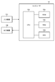
- FIG. 1 is a block diagram showing the configuration of the reading support system according to the first embodiment.
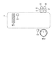
- FIG. 2 is a schematic view illustrating a meter.
- 3 to 12 are diagrams for explaining the processing by the reading support system according to the first embodiment.
- the reading support system 1 is used when reading a value (indication) indicated by the instrument from an image including the instrument.
- the target instrument type is arbitrary.
- the reading support system 1 is used for reading the readings of the circular instruments M1 and M2 as shown in FIGS. 2(a) and 2(b).
- the circular instrument includes a pointer In that rotates about a certain point, a plurality of scales Sc that are marked around the center point, and a number Nu that corresponds to at least a part of the plurality of scales Sc. including.
- the scales Sc are arranged in a circular shape or an arc shape. In the round instrument, either the pointer In or the scale Sc rotates along the arrangement direction of the scale Sc, and the pointer In points a specific scale Sc to indicate a value.
- the reading support system 1 can also be used for reading the reading in the vertical measuring instrument M3 as shown in FIG. 2C or the horizontal measuring instrument M4 as shown in FIG. 2D.
- the vertical instrument and the horizontal instrument include a pointer In, a plurality of scales Sc arranged in one direction, and a number Nu written corresponding to at least a part of the plurality of scales Sc.
- either the pointer In or the scale Sc moves along the arrangement direction of the scale Sc, and the pointer In points a specific scale Sc, thereby indicating a value.
- the reading support system 1 includes a processing device 10 and a storage device 20.
- the processing device 10 includes an extraction unit 14.
- the processing device 10 further includes a reception unit 11, an extraction unit 12, a correction unit 13, a reading unit 15, and an output unit 16.
- an external imaging device takes a picture of the instrument and acquires a still image.
- the imaging device transmits the acquired image to the processing device 10.
- the imaging device may store the image in the storage device 20.
- the processing device 10 accesses the storage device 20 and acquires an image.
- a moving image may be taken by the imaging device.
- the imaging device cuts out a still image from the moving image and transmits the still image to the processing device 10 or the storage device 20.
- the captured image may include something other than the instrument.
- the reception unit 11 receives an image input to the processing device 10.
- the reception unit 11 outputs the image to the extraction unit 12.
- FIG. 3A is an example of an image input to the processing device 10.
- the extraction unit 12 extracts, from the input image, a candidate for a region where the instrument is photographed.
- an image captured by the imaging device and input to the processing device 10 is referred to as an input image.
- a candidate of a region, which is a part of the input image and in which the instrument is photographed, is called a candidate region.
- the extraction unit 12 includes a contour extraction unit 12a and a selection unit 12b.
- the contour extraction unit 12a extracts a contour (edge) included in the input image based on, for example, a difference in brightness or a difference in brightness in the input image.
- the contour extraction unit 12a may appropriately perform processing on the input image. For example, the contour extraction unit 12a converts the input image to gray scale, binarizes it, and extracts contours from the binary image.
- the selection unit 12b extracts a region surrounded by a contour from the input image. For example, the selection unit 12b compares the maximum length and the area in a certain direction for each region with a preset threshold value. The selection unit 12b selects, as a candidate region, a region whose maximum length and area exceed the threshold value. This excludes areas that are too small, or areas that are significantly different in shape from the instrument.
- FIG. 3B shows the candidate region CR1 extracted from the input image II shown in FIG. The selection unit 12b outputs the candidate area to the correction unit 13.
- the correction unit 13 appropriately performs projective transformation on the candidate area.
- the outer edge of the instrument or the outer edge of the instrument display panel is circular or square.
- the correction unit 13 performs projective transformation on the candidate area so that the outer edge of the candidate area becomes a rectangle.
- the candidate area is elliptical or oval
- the correction unit 13 performs projective transformation on the candidate area so that the outer edge of the candidate area becomes circular.
- the distortion of the candidate region is corrected by the projective transformation.
- the correction unit 13 outputs the corrected candidate area to the extraction unit 14.
- the extraction unit 14 extracts a number area, a scale area, and a pointer area from the candidate area.
- the extraction unit 14 includes a numeral region extraction unit 14a, a type determination unit 14b, a scale region extraction unit 14c, and a pointer region extraction unit 14d.
- the numerical area extraction unit 14a extracts a character candidate that is a candidate for an area in which a character appears from the candidate area.
- the character candidate is a part of the candidate area.
- the character candidates include numbers and alphabets. Alternatively, the character candidates may include objects other than characters such as deposits on instruments and noise in images.
- a scene character recognition technique is used for extracting character candidates.
- the size of the extracted character candidate is determined based on the size of the candidate area.
- the numerical area extracting unit 14a performs the following process for each character candidate. First, the numerical area extracting unit 14a calculates the collation rates of the character candidates and the numbers. For example, the numerical area extraction unit 14a calculates the similarity of the feature amount between the character candidate and the image of the number registered in advance as the matching rate. Next, the numeral area extracting unit 14a rotates the character candidates by a preset angle. The numeral area extracting unit 14a again calculates the collation rates of the rotated character candidates and the numerals. After that, the rotation of the character candidates and the calculation of the matching rate are repeated until the number of rotations reaches a predetermined number or the total rotation angle reaches a predetermined threshold value.
- the horizontal axis represents the rotation angle A.
- the vertical axis represents the matching rate R.
- FIG. 4(a) shows the result when the character candidates include numbers.
- the numerical area extraction unit 14a calculates the rate of change in the matching rate with respect to the change in rotation angle from the result. For example, when the ratio exceeds the threshold value, the numerical area extracting unit 14a determines that the character candidate includes a numeral. In the example of FIG. 4A, the number area extracting unit 14a determines that the character candidate includes a number based on the result of the shaded portion.
- FIG. 4B shows the result when the character candidates do not include a number.
- the change rate of the matching rate with respect to the change of the rotation angle is small.
- the numerical area extracting unit 14a excludes a character candidate that does not include a numeral from the plurality of character candidates.
- the numerical area extracting unit 14a determines the minimum range surrounding each character candidate for each character candidate determined to include a numeral.
- the numeral area extracting unit 14a may rotate the candidate area based on the result of the rotation angle and the matching rate. For example, when the numeral area extracting unit 14a determines that the character candidate includes a numeral, it records the angle at which the maximum matching rate is obtained. When the determination is completed for all the character candidates, the numerical area extracting unit 14a calculates the average value of those angles. The number area extraction unit 14a rotates the candidate areas by the calculated average value.
- the minimum range enclosing the numbers can be obtained as shown in FIG. 3C.
- Each of these minimum ranges is extracted as a numerical area R1 from the candidate area CR1.
- the numeral area extracting unit 14a outputs the positions of the respective numeral areas in the extracted plural numeral areas and candidate areas to the type determining unit 14b.
- information regarding the numerical area may be output from the numerical area extracting unit 14a to the correcting unit 13.
- the numerical area extracting unit 14a acquires the length L1 and the length L2 for at least a part of the extracted numerical area and outputs them to the correcting unit 13.
- the correction unit 13 calculates the distortion of the candidate area based on the ratio of the length L1 and the length L2, and projectively transforms the candidate area again so as to correct this distortion.
- the candidate area after the projective transformation is again processed by the number area extracting unit 14a.
- the scale area and the pointer area having smaller distortion. If the distortion of the numeral area, the scale area, and the pointer area is small, the reading accuracy of the instrument reading can be improved.
- the type determination unit 14b determines the type of instrument shown in the input image based on the position of the number area. For example, as shown in FIG. 3C, when the plurality of numeral regions R1 are arranged in a curved line in the circumferential direction, the type determining unit 14b indicates that the measuring instrument shown in the input image is a round measuring instrument. To decide. When the numbers are lined up in one direction, the type determination unit 14b determines that the measuring instrument shown in the input image is a vertical measuring instrument or a horizontal measuring instrument. The type determining unit 14b outputs the type of instrument to the scale area extracting unit 14c.
- the scale area extraction unit 14c extracts the scale area from the candidate area. For example, the processing by the scale area extracting unit 14c changes according to the result of the determination by the type determining unit 14b. Specifically, when the type of instrument is determined to be round, the scale area extraction unit 14c performs polar coordinate conversion on the candidate area. For example, when the candidate area is circular, the center of the circle is the center of the polar coordinate system. When the candidate area is a quadrangle, the intersection of the diagonal lines is the center of the polar coordinate system. When the center of the polar coordinate system is set, the candidate area is transformed into polar coordinates.
- FIG. 5A shows the result of polar coordinate conversion of the candidate area CR1 of FIG. 3B.
- the scale area extraction unit 14c binarizes the candidate area CR2 after polar coordinate conversion shown in FIG. As a result, as shown in FIG. 5B, the binarized candidate region CR3 is obtained.
- the scale area extracting unit 14c extracts a contour from the binarized candidate area CR3. As a result, as shown in FIG. 5C, the candidate region CR4 with the contour emphasized is obtained.
- the scale area extracting unit 14c sets a plurality of first sub-areas SRA as shown in FIG. 6A for the image from which the contour is extracted.
- the plurality of first sub regions SRA are arranged in the first direction D1.
- the length of the first sub-region SRA in the second direction D2 perpendicular to the first direction D1 is the same as the length of the candidate region CR4 in the second direction D2, for example.
- the number of set first sub-regions SRA is determined based on the size of the candidate region. In the example of FIG. 6A, ten first sub areas SRA1 to SRA10 are set.
- the first direction D1 corresponds to the radial direction before polar coordinate conversion.
- the radial direction is the direction from the center of rotation of the instrument or scale to the scale.
- the second direction D2 corresponds to the circumferential direction.
- the circumferential direction is the direction in which the scales are arranged.
- the scale area extracting unit 14c counts the number of horizontal lines in each first sub area SRA.
- the horizontal line refers to a line extending in the first direction D1.
- FIG. 6B is an enlarged image of the portion P1 shown in FIG.
- FIG. 6C is an enlarged image of the portion P2 shown in FIG.
- the scale area extraction unit 14c sets a mask Ma in each first sub area SRA as shown in FIGS. 6B and 6C.
- the mask Ma is set so that the length in the second direction D2 of the region not covered with the mask Ma becomes a specified value.
- the scale area extraction unit 14c confirms whether the area not covered with the mask Ma has a contour. If there is a contour, the scale area extraction unit 14c measures the length of the contour in the first direction D1.
- the contour is determined to be a horizontal line.
- the contour E1 between the masks Ma is not determined to be a horizontal line.
- the contours E2 and E3 between the masks Ma are determined to be horizontal lines.
- the scale area extracting unit 14c counts the number of horizontal lines in each first sub area SRA while changing the position of the mask Ma.
- the scale area extraction unit 14c totals the number of horizontal lines for each first sub area SRA. For example, the result shown in FIG. 6D is obtained from the image shown in FIG. FIG. 6D shows the sum Sum of the number of horizontal lines at each point in the first direction D1. From this result, the scale area extraction unit 14c determines that the first sub-area in which the total number of horizontal lines exceeds a predetermined threshold is the range (scale range) where the scale of the instrument exists. In the example of FIG. 6D, the scale area extraction unit 14c determines the positions of the first sub areas SRA8 to SRA10, which are shaded, as the scale range. The scale area extraction unit 14c extracts the scale range from the candidate area based on the determination result. For example, by this processing, the scale range SA shown in FIG. 7A is extracted from the image shown in FIG.
- the scale area extraction unit 14c sets a plurality of second sub areas SRB in the scale range SA from which the contour is extracted, as shown in FIG. 7B, for example.
- the plurality of second sub regions SRB are arranged in the second direction D2. In the example of FIG. 7B, nine second sub areas SRB1 to SRB9 are set.
- the scale area extraction unit 14c totals the number of horizontal lines for each second sub area SRB, similarly to the above-described total calculation of the number of horizontal lines in each second sub area SRB.
- FIG. 7(c) can be obtained from the image shown in FIG. 7(b).
- FIG. 7C shows the sum Sum of the number of horizontal lines in each second sub region SRB.
- the scale area extraction unit 14c determines the second sub-area in which the total number of horizontal lines exceeds the threshold value as the area where the scale of the instrument exists (scale area).
- the scale area extraction unit 14c determines the shaded positions of the second sub areas SRB1 to SRB6 and SRB9 as the scale area of the instrument. Based on this result, the scale area extraction unit 14c extracts the scale area from the scale range.
- the scale area extraction unit 14c extracts the scale area from the candidate area based on this result. For example, as shown in FIG. 7D, the scale area R2 is extracted from the candidate area CR1 rotated by the number area extracting unit 14a. The scale area extracting unit 14c outputs the extracted scale area to the pointer area extracting unit 14d.
- the scale area extraction unit 14c may further execute the following processing when the candidate area has undergone polar coordinate conversion.
- the scale area extracting unit 14c extracts scales from the scale area. For example, the scale area extraction unit 14c identifies horizontal lines arranged in the second direction D2 as scales in the scale area. As shown in FIG. 8, the scale area extraction unit 14c calculates the distance D between the scale Sc and the end of the candidate area after the polar coordinate conversion in the first direction D1. If the center of the polar coordinate system coincides with the center of the actual round instrument, then the distances will be approximately equal. Variations in distance indicate that the center of the polar coordinate system does not match the center of the actual round instrument.
- the scale area extracting unit 14c acquires the maximum value of the distance, the minimum value of the distance, the position of the horizontal line having the maximum distance, and the position of the horizontal line having the minimum distance. At the position where the distance is the minimum, the center of the actual round instrument is located farther from the center of the polar coordinate system in the first direction D1. At the position where the distance is maximum, the actual center of the round instrument is closer to the center of the polar coordinate system in the first direction D1.
- the scale area extracting unit 14c corrects the center of the polar coordinate system on the basis of these pieces of information, and transforms the candidate area again into polar coordinates.
- the scale area extracting unit 14c extracts the scale area again from the candidate area newly polar-transformed. Thereby, the scale area can be extracted more accurately. It is possible to improve the reading accuracy of the reading of the instrument.
- the processing of the scale area extracting unit 14c when the instrument is round is described. Even when the measuring instrument is of a vertical type or a horizontal type, the same processing as above is executed. That is, the scale area extraction unit 14c sets a plurality of first sub-areas for the candidate area in which the scales are arranged in one direction. The scale area extraction unit 14c extracts the scale range from the candidate area based on the total number of horizontal lines in each first sub area. The scale area extraction unit 14c sets a plurality of second sub areas for the scale range. The scale area extracting unit 14c extracts the scale area from the scale range based on the total number of horizontal lines in each second sub area.
- the pointer area extraction unit 14d sets a detection area for detecting the pointer in the candidate area.
- the type determining unit 14b determines that the measuring instrument is circular
- the pointer area extracting unit 14d sets a circular pointer area.
- the measuring instrument is determined to be the vertical type or the horizontal type
- the pointer area extracting unit 14d sets a rectangular pointer area.
- the pointer area extraction unit 14d determines the position of the pointer based on the information obtained from the detection area.
- the pointer area extracting unit 14d extracts the pointer area based on the determination result of the pointer position in each detection area while changing the size of the detection area.
- the pointer area extraction unit 14d sets a circular detection area.
- the center of this detection area is set to the center of the candidate area.
- the diameter of the circle of the detection area is set to a predetermined value.
- the pointer area extraction unit 14d performs polar coordinate conversion on the detection area.
- FIG. 9A the circular detection region DR1 is set as the candidate region.
- FIG. 9B shows a result of binarizing the detection region DR1 shown in FIG. 9A by polar coordinate conversion.
- the pointer area extraction unit 14d calculates the sum of the luminances of the plurality of pixels arranged in the first direction D1 at each point in the second direction D2 of the polar coordinate-converted detection area. When this process is executed on the binarized detection area, the number of white pixels arranged in the first direction D1 at each point in the second direction D2 is calculated.
- FIG. 9C shows the relationship between the position P in the second direction D2 and the total sum Sum of the brightness in the detection area shown in FIG. 9B.
- the pointer area extracting unit 14d determines that the pointer is present, for example, at the position in the second direction D2 at which the total luminance is the minimum.
- the pointer area extracting unit 14d compares the distribution range at the position where the brightness is the minimum with the distribution range threshold. When the distribution range is equal to or less than the distribution range threshold, the pointer area extraction unit 14d sets the averaged position as the position of the pointer.
- the distribution range threshold is set to a distance in the second direction D2 corresponding to an angle of 10 degrees in the polar coordinate system. The pointer area extracting unit 14d does not detect the position of the pointer when the distribution range exceeds the distribution range threshold.
- the pointer area extraction unit 14d changes the size of the detection area. For example, when a small detection area is initially set, the pointer area extraction unit 14d increases the detection area.
- FIG. 10A shows another example of the detection area. The diameter of the detection region DR2 shown in FIG. 10A is longer than the diameter of the detection region DR1 shown in FIG. 9A.
- FIG. 10B shows a result of binarizing the detection region DR2 shown in FIG. 10A by polar coordinate conversion. Similarly for the detection area DR2 shown in FIG. 10B, the pointer area extraction unit 14d calculates the sum of the luminances of the plurality of pixels arranged in the first direction D1 at each point in the second direction D2.
- FIG. 10C shows the relationship between the position P in the second direction D2 and the total sum Sum of brightness in the detection area shown in FIG.
- the pointer area extraction unit 14d repeats changing the size of the detection area and determining the pointer position in the detection area described above. These processes are repeated until the size of the detection area satisfies the predetermined condition. For example, the detection area is repeated until it reaches the scale area. In a typical round instrument, at least a portion of the pointer is inside the scale area. When the detection area reaches the scale area, at least a part of the pointer is present in the detection area. Alternatively, the above-described processing may be repeated until the size of the detection area reaches a specific value calculated based on the size of the candidate area.
- FIG. 11 shows the results obtained by repeating the change of the size of the detection area and the determination of the pointer position in the detection area.
- the horizontal axis represents the size S of the detection area
- the vertical axis represents the position P of the pointer in the second direction D2. If the instrument is round, the size of the detection area corresponds to the diameter (radius or diameter). The position in the second direction D2 corresponds to the angle.
- the pointer area extraction unit 14d determines the first range and the second range of the size of the detection area based on the result of the change in the size of the detection area and the position of the pointer. When the size is within the first range, the change in the pointer position is small. When the size is within the second range, the change in the pointer position is large. For example, the pointer area extracting unit 14d calculates the ratio of the change in the pointer position to the change in the size at each point on the horizontal axis in the graph shown in FIG. The pointer area extracting unit 14d extracts, as the first range, a continuous portion in which the ratio is equal to or less than the first threshold value. The pointer area extracting unit 14d extracts, as the second range, a portion where the ratio exceeds the second threshold and is continuous. The second threshold is a value higher than the first threshold.
- FIG. 11 shows an example of the first range Ra1 and the second range Ra2.
- one end of the pointer is close to the scale and the other end of the pointer projects to the opposite side of the center of rotation.
- the detection area is small, as shown in FIGS. 9B and 9C, the total luminance value is large at both the position where one end of the pointer is present and the position where the other end is present. Therefore, it is not easy to accurately identify one end of the pointer.
- the change in the pointer position becomes large as in the second range Ra2 shown in FIG.
- FIGS. 10 shows an example of the first range Ra1 and the second range Ra2.
- the total luminance at the position where one end of the pointer is present is larger than the total luminance at the position where the other end is present. Also grows. As a result, one end of the pointer can be discriminated from the other end, and the change in the pointer position is reduced.
- the pointer area extraction unit 14d determines the size of the pointer area based on the upper limit of the size (diameter) of the first range.
- the pointer area extracting unit 14d may further determine the size of the pointer area based on the upper limit value of the size of the second range or the lower limit value of the size (diameter) of the first range.
- a circular pointer region R3 is extracted.
- the inner diameter IR of the pointer region R3 is set based on the upper limit of the size of the second range or the lower limit of the size of the first range.
- the outer diameter OR of the pointer region R3 is set based on the upper limit value of the length of the first range. In other words, the pointer area is set so as not to include the detection area whose length is within the second range. As a result, the reading accuracy of the reading can be improved.
- the number area, scale area, and pointer area are extracted from the candidate area.
- the extraction unit 14 outputs each extracted area to the reading unit 15.
- the reading unit 15 reads the reading of the instrument using the number area, the scale area, and the pointer area extracted by the extracting unit 14. Specifically, the reading unit 15 includes a scale recognizing unit 15a, a numeral recognizing unit 15b, a pointer recognizing unit 15c, a graduation joining unit 15d, and a calculating unit 15e.
- the scale recognizing unit 15a recognizes the scale of the instrument based on the brightness difference in the scale area extracted by the extracting unit 14. For example, the scale recognizing unit 15a determines a reference line and calculates an angle between the reference line and each scale.
- the number recognition unit 15b recognizes a number in the number area extracted by the extraction unit 14.
- the pointer recognition unit 15c detects the angle between the reference line and the pointer based on the information on the pointer region extracted by the extraction unit 14.
- the scale joining part 15d associates the scale recognized by the scale recognition part 15a with the number recognized by the number recognition part 15b.
- the calculator 15e calculates the instrument reading based on the angle of each scale, the correspondence information between the scale and the numbers, and the angle of the pointer.
- the reading unit 15 sends the calculated reading to the output unit 16.
- the output unit 16 outputs, for example, information based on the calculated reading to an external output device.
- the information includes read readings.
- the information may include a result calculated based on the read reading.
- the output unit 16 may calculate another value based on the read plurality of readings and output the calculation result.
- the output unit 16 may further output information such as the read time.
- the output unit 16 may output a file including information such as the read reading number and the read time in a predetermined format such as CSV.
- the output unit 16 may send data to an external server using FTP (File Transfer Protocol) or the like.
- the output unit 16 may perform database communication and insert data into an external database server using ODBC (Open Database Connectivity) or the like.
- FTP File Transfer Protocol
- ODBC Open Database Connectivity
- the processing device 10 includes a processing circuit including, for example, a central processing unit.
- the storage device 20 includes, for example, at least one of a hard disk drive (HDD), a network connection hard disk (NAS), an embedded multimedia card (eMMC), a solid state drive (SSD), and a solid state hybrid drive (SSHD). ..
- the processing device 10 and the storage device 20 are connected by wire or wirelessly. Alternatively, the processing device 10 and the storage device 20 may be connected to each other via a network.
- the reception unit 11 receives the input image (step S11).
- the contour extracting unit 12a extracts a contour from the input image (step S12a).
- the selection unit 12b selects, as candidate regions, some regions that satisfy the conditions from the regions surrounded by the contours. (Step S12b).
- the correction unit 13 performs projective transformation on the candidate area and corrects it. (Step S13).
- the number area extracting unit 14a extracts a plurality of number areas from the candidate areas (step S14a).
- the type determining unit 14b determines the type of instrument based on the position of each of the plurality of numeral regions (step S14b).
- the scale area extracting unit 14c extracts the scale area from the candidate area (step S14c).
- the pointer area extracting unit 14d extracts the pointer area from the candidate area (step S14d).
- the reading unit 15 reads the indication of the pointer (step S15).
- the output unit 16 outputs information based on the reading result (step S16).
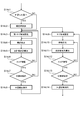
- FIG. 14 is a flowchart specifically showing the process of step S14a executed by the number area extracting unit 14a.
- the numerical area extracting unit 14a extracts character candidates from the candidate area (step S14a1).
- the numerical area extracting unit 14a rotates one of the plurality of character candidates (step S14a2).
- the numerical area extracting unit 14a calculates a matching rate for the rotated character candidates (step S14a3).
- the numeral area extracting unit 14a records the calculated matching rate (step S14a4).
- the number area extracting unit 14a determines whether the number of rotations of the character candidate is less than or equal to a threshold value (step S14a5). When the number of rotations is less than or equal to the threshold value, steps S14a2 to S14a4 are repeated.
- the numerical area extracting unit 14a determines whether the change amount of the matching rate is less than or equal to the threshold value (step S14a6). When the change amount of the matching rate is less than or equal to the threshold value, the process proceeds to step S14a8.
- the numeral area extracting unit 14a determines the minimum range surrounding the numeral included in the character candidate (step S14a7). The number area extracting unit 14a determines whether there is another character candidate for which the number recognition has not been tried (step S14a8). When there are other character candidates, the numerical area extracting unit 14a executes step S14a2 for the other character candidates. When there is no other character candidate, the numerical area extracting unit 14a extracts the minimum range determined so far from the candidate area as a numerical area (step S14a9).
- FIG. 15 is a flowchart specifically showing the process of step S14c executed by the scale area extracting unit 14c.
- the scale area extracting unit 14c refers to the type of the instrument determined by the type determining unit 14b, and determines whether the instrument is round (step S14c1). If the instrument is not round, the process proceeds to step S14c3.
- the scale area extracting unit 14c polar-transforms the candidate area (step S14c2).
- the scale area extraction unit 14c sets a plurality of sub area strings for the candidate area (step S14c3).
- the scale area extracting unit 14c detects a horizontal line included in the candidate area (step S14c4).
- the scale area extraction unit 14c calculates the total number of horizontal lines in the sub area row (step S14c5).
- the scale area extracting unit 14c may execute steps S14c6 and S14c7.
- the scale area extracting unit 14c uses the maximum value of the total number of horizontal lines as a score, and determines whether the score exceeds a threshold value (step S14c7). When the score is below the threshold, the horizontal line may not be detected properly.
- the scale area extracting unit 14c changes the horizontal line detection condition and executes step S14c4 again.
- the scale area extraction unit 14c determines whether the resolution is less than or equal to the threshold (step S14c8).
- the resolution is represented, for example, by the ratio of the size of one first sub-region to the total size of the extraction region.
- the scale area extracting unit 14c changes the setting condition of the first sub area, and executes step S14c3 again.
- the scale area extraction unit 14c extracts the scale range from the candidate area based on the total number of horizontal lines in each first sub area (step S14c8).
- the scale area extraction unit 14c sets a plurality of second sub areas for the scale range (step S14c9).
- the scale area extraction unit 14c detects a horizontal line included in the scale range (step S14c10).
- the scale area extracting unit 14c calculates the total number of horizontal lines in the second sub area (step S14c11).
- the scale area extraction unit 14c may execute steps S14c12 and S14c13.
- the scale area extraction unit 14c uses the maximum value of the total number of horizontal lines as a score, and determines whether the score exceeds a threshold value (step S14c12). When the score is below the threshold, the horizontal line may not be detected properly.
- the scale area extracting unit 14c changes the horizontal line detection condition and executes step S14c10 again.
- the scale area extraction unit 14c determines whether the resolution is less than or equal to the threshold value (step S14c13). When the resolution exceeds the threshold value, the scale area extraction unit 14c changes the setting condition of the second sub area, and executes step S14c9 again. When the resolution is equal to or lower than the threshold value, the scale area extraction unit 14c extracts the scale area from the scale range based on the total number of horizontal lines in each second sub area (step S14c14).
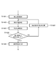
- FIG. 16 is a flowchart specifically showing the process of step S14d executed by the pointer area extracting unit 14d.
- the pointer area extraction unit 14d sets a detection area in the candidate area (step S14d1).
- the pointer area extraction unit 14d determines the position of the pointer in the set detection area (step S14d2).
- the pointer area extracting unit 14d records the determined position of the pointer (step S14d3).
- the pointer area extraction unit 14d determines whether or not the detection area satisfies the condition (step S14d4). For example, the pointer area extraction unit 14d determines whether the detection area reaches the scale area (is overlapping).
- the pointer area extraction unit 14d changes the length of the detection area in the specific direction (step S14d5).
- the pointer area extracting unit 14d executes step S14d2 again based on the detection area whose length has been changed.
- the pointer area extracting unit 14d extracts the pointer area from the candidate area based on the relationship between the change in length and the change in pointer position (step S14d6).
- the image is processed according to the type of instrument.
- the arrangement of scales differs depending on the type of instrument.
- the accuracy of reading the reading can be improved by executing the processing according to the type of the measuring instrument.
- a method of registering the type of instrument to be imaged in advance can be considered.
- the processing device 10 refers to the registered instrument type and determines the process to be executed.
- the reading cannot be properly read unless the type of the instrument is registered in advance.
- the numeral area extracting unit 14a extracts a numeral area including a plurality of numerals of the measuring instrument from the candidate area. Then, the type determination unit 14b determines the type of instrument based on the positions of the plurality of numeral regions. That is, according to the reading support system 1 according to the first embodiment, the type of instrument is automatically determined from the image. By using the reading support system 1, the user does not need to register the type of instrument in advance when reading readings.
- the reading of the measuring instrument When reading the reading of the measuring instrument from the image, the number area, the scale area, and the pointer area are extracted from the candidate area. Then, the reading of the instrument is read based on these extracted regions. At this time, it is desirable that the number area, the scale area, or the pointer area be extracted more appropriately. By more appropriately extracting the numeral area, the scale area, or the pointer area, the reading can be read with higher accuracy. For example, there is a method in which the position where the scale is present in the instrument is registered in advance, and the scale region is extracted from the candidate region based on the registration information and the brightness in the image. However, with this method, if the actual scale area is different from the registered position, the scale area cannot be extracted properly. In the case of sequentially reading readings from images of a plurality of different instruments, it is necessary to associate the instruments in the image with the positions of the scales on the instruments, which requires a long time in advance.
- the scale area extracting unit 14c executes the following processing.
- the scale area extracting unit 14c sets, for the candidate area, a plurality of first sub areas arranged in the first direction in the second direction.
- the scale area extracting unit 14c detects the number of line segments extending in the second direction in each of the first sub areas.
- the scale area extracting unit 14c extracts a part of the candidate area in the second direction as a scale range in which the scale of the instrument exists, based on the number of detected line segments.
- the range in which the scale exists can be more appropriately extracted from the candidate region without the need to pre-register the position of the scale region in the instrument. Therefore, in reading the reading, the user does not need to register the position of the scale of the instrument in advance.
- By more appropriately extracting the scale range it is possible to improve the accuracy of reading the reading using the scale range.
- the scale area extraction unit 14c further executes the following processing.
- the scale area extracting unit 14c sets a plurality of second sub areas arranged in the second direction in the first direction with respect to the scale range.
- the scale area extracting unit 14c detects the number of line segments extending in the second direction in each of the second sub areas.
- the graduation area extraction unit 14c extracts a part of the graduation range in the first direction as a graduation area where the graduation of the instrument exists, based on the number of detected line segments.
- the pointer area extracting unit 14d executes the following processing.
- the pointer area extraction unit 14d sets a circular detection area for detecting the pointer of the measuring instrument with respect to the candidate area when the type of measuring instrument is round.
- the pointer area extracting unit 14d determines the angle of the pointer in the detection area of each size while changing the size of the detection area, and extracts the pointer area where the pointer exists from the candidate area based on the determination result. .. According to these processes, the pointer area can be more appropriately extracted from the candidate area without the need to pre-register the position of the pointer area in the instrument.
- the pointer area extraction unit 14d determines the first range and the second range of the size based on the result of the change in the angle with respect to the change in the size. Then, the pointer area extracting unit 14d extracts a circular pointer area having an outer diameter based on the upper limit value of the first range and an inner diameter based on the upper limit value of the second range. According to this processing, a region that has a small contribution to recognition of the pointer can be excluded from the pointer region. The accuracy of reading can be improved by using the pointer area extracted by this process for reading the reading.
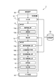
- FIG. 17 is a block diagram showing the configuration of the reading support system according to the second embodiment.
- the reading support system 2 according to the second embodiment further includes an imaging device 30.
- the imaging device 30 captures an image of an instrument and generates an image.
- the imaging device 30 transmits the generated image to the processing device 10.
- the imaging device 30 may store the image in the storage device 20.
- the processing device 10 accesses the storage device 20 and refers to the stored image.
- the imaging device 30 acquires a moving image
- the imaging device 30 extracts a still image from the moving image and transmits the still image to the processing device 10.
- the imaging device 30 includes, for example, a camera.
- the processing device 10 transmits information based on the identified and read characters to the output device 40.
- the output device 40 outputs the information received from the processing device 10 so that the user can recognize it.
- the output device 40 includes, for example, at least one of a monitor, a printer, and a speaker.
- the processing device 10, the storage device 20, the imaging device 30, and the output device 40 are connected to each other, for example, by wire or wirelessly. Alternatively, these may be connected to each other via a network. Alternatively, at least two of the processing device 10, the storage device 20, the imaging device 30, and the output device 40 may be incorporated in one device. For example, the processing device 10 may be integrated with the image processing unit of the imaging device 30 or the like.
- FIG. 18 is a block diagram showing the configuration of the reading support system according to the third embodiment.
- the reading support system 3 according to the third embodiment further includes a moving body 50.
- the moving body 50 moves within a predetermined area.
- a measuring instrument is provided in the area where the moving body 50 moves.
- the moving body 50 is, for example, an automated guided vehicle (AGV).
- the moving body 50 may be a flying body such as a drone.
- the moving body 50 may be a robot that walks independently.
- the moving body 50 may be a forklift, a crane, or the like that performs a predetermined work unmanned.
- the processing device 10 and the imaging device 30 are mounted on the moving body 50.
- the processing device 10 may be provided separately from the mobile body 50 and may be connected to the mobile body 50 via a network.
- the imaging device 30 photographs the measuring instrument and generates an image.
- the reading support system 3 may further include an acquisition device 60.
- the acquisition device 60 is mounted on the moving body 50.
- an identifier having unique identification information is provided corresponding to the instrument.
- the acquisition device 60 acquires the identification information included in the identification body.
- the reading support system 3 may further include a control device 70.
- the control device 70 controls the moving body 50.
- the moving body 50 moves in a predetermined area based on a command transmitted from the control device 70.
- the control device 70 may be mounted on the moving body 50 or may be provided separately from the moving body 50.
- the control device 70 includes a processing circuit including, for example, a central processing unit. One processing circuit may function as both the processing device 10 and the control device 70.
- the identifier is a radio frequency (RF) tag having ID information.
- the identifier emits an electromagnetic field or radio wave containing ID information.
- the acquisition device 60 receives the electromagnetic field or the radio wave emitted from the identification body and acquires the ID information.
- the identifier may be a one-dimensional or two-dimensional barcode.
- the acquisition device 60 is a barcode reader. The acquisition device 60 acquires the identification information included in the barcode by reading the barcode.
- the processing device 10 may further include a tying unit 17.
- the acquisition device 60 acquires the identification information
- the acquisition device 60 transmits the identification information to the processing device 10.
- the associating unit 17 associates the transmitted identification information with the read character.
- the associated information is stored in the storage device 20.
- FIG. 19 is a schematic diagram illustrating the operation of the reading support system according to the third embodiment.
- the moving body 50 is a moving body that moves along a predetermined trajectory T.
- An imaging device 30 and an acquisition device 60 are mounted on the moving body 50.
- the processing device 10 may be mounted on the moving body 50 or may be provided separately from the moving body 50.
- the track T is provided so that the moving body 50 passes in front of the instruments M11 and M12.
- the moving body 50 moves along the trajectory T, and decelerates or stops when the imaging device 30 reaches a position where the instrument M11 or M12 can be photographed.
- the moving body 50 transmits an imaging command to the imaging device 30.
- the image capturing command may be transmitted from the control device 70 to the image capturing device 30.
- the imaging device 30 photographs the measuring instrument M11 or M12 while the moving body 50 is decelerating or stopping.
- the moving body 50 moves along the trajectory T at such a speed that the imaging device 30 can photograph the measuring instrument M11 or M12 without shaking.
- a command for image pickup is transmitted from the moving body 50 or the control device.
- the imaging device 30 photographs the instrument M11 or M12.
- the imaging device 30 transmits the image to the processing device 10 mounted on the moving body 50 or provided separately from the moving body 50.
- An identifier ID1 is provided near the meter M11.
- An identifier ID2 is provided near the meter M12.
- the acquisition device 60 acquires the identification information of the identification body ID1 or ID2 while the moving body 50 is decelerated or stopped.
- the moving body 50 moves in front of the measuring instrument M11.
- the imaging device 30 photographs the instrument M11 and generates an image.
- the processing device 10 identifies the character displayed on the meter M11 from this image.
- the acquisition device 60 acquires the identification information of the identification object ID1 corresponding to the instrument M11.
- the processing device 10 associates the identified character with the identification information.
- the processing by the processing device 10 is particularly suitable when the imaging device 30 is mounted on the moving body 50 and sequentially photographs a plurality of measuring instruments. Since the type of instrument is automatically determined by the number area extraction unit 14a and the type determination unit 14b, the user does not need to register the type of instrument in advance. There is a possibility that captured images may vary depending on the state of the moving body 50. According to the processing performed by the processing device 10, even if there are variations in images, the number area extracting unit 14a, the scale area extracting unit 14c, and the pointer area extracting unit 14d select a candidate area from the numeral area, the scale area, and the pointer. The area is automatically extracted. Therefore, the reading accuracy of the reading can be improved.
- FIG. 20 is a block diagram showing the hardware configuration of the reading support system according to the embodiment.
- the processing device 10 of the reading support systems 1 to 3 is a computer, and includes a ROM (Read Only Memory) 10a, a RAM (Random Access Memory) 10b, a CPU (Central Processing Unit) 10c, and an HDD (Hard Disk Drive) 10d.
- ROM Read Only Memory
- RAM Random Access Memory
- CPU Central Processing Unit
- HDD Hard Disk Drive
- the ROM 10a stores a program that controls the operation of the computer.
- the ROM 10a stores programs necessary for causing the computer to function as the control unit 10.
- the RAM 10b functions as a storage area in which the programs stored in ROM 10a are expanded.
- the CPU 10c includes a processing circuit.
- the CPU 10c reads the control program stored in the ROM 10a and controls the operation of the computer according to the control program.
- the CPU 10c expands various data obtained by the operation of the computer in the RAM 10b.
- the HDD 10d stores information necessary for reading and information obtained in the reading process.
- the HDD 10d functions, for example, as the storage device 20 shown in FIG.
- the control unit 10 may have an eMMC (embedded MultiMedia Card), SSD (Solid State Drive), SSHD (Solid State Hybrid Drive), etc. instead of the HDD 10d.
- eMMC embedded MultiMedia Card
- SSD Solid State Drive
- SSHD Solid State Hybrid Drive
- An input device 10e and an output device 10f may be connected to the control unit 10.
- the input device 10e is used by the user to input information to the control unit 10.
- the input device 10e includes at least one of a microphone, a keyboard, a mouse (voice input), and a touch pad.
- the information transmitted from the control unit 10 is output to the output device 10f.
- the output device 10f includes at least one of a monitor, a speaker, a printer, and a projector.
- a device having both functions of the input device 10e and the output device 10f, such as a touch panel, may be used.
- the same hardware configuration as in FIG. 20 can be applied to the control device 70 in the reading support system 3.
- one computer may function as the processing device 10 and the control device 70.
- the respective processes and functions of the processing device 10 and the control device 70 may be realized by cooperation of more computers.
- the reading support system By using the reading support system, the reading support method, and the moving body according to the embodiments described above, it becomes possible to read the number displayed on the instrument with higher accuracy.
- a program for operating a computer as a reading support system, it becomes possible to cause the computer to read the numbers displayed on the instrument with higher accuracy.
- the processing of the above various data is executed based on, for example, a program (software).
- the computer stores the program and reads the program to perform the processing of the above various information.
- the above-described processing of various kinds of information is a magnetic disk (flexible disk, hard disk, etc.), optical disk (CD-ROM, CD-R, CD-RW, DVD-ROM, DVD ⁇ R) as a program that can be executed by a computer. , DVD ⁇ RW, etc.), semiconductor memory, or other recording medium.
- the information recorded on the recording medium can be read by a computer (or an embedded system).
- the recording format storage format
- the computer reads the program from the recording medium and causes the CPU to execute the instruction described in the program based on the program.
- acquisition (or reading) of the program may be performed via a network.
- the processing device and the control device according to the embodiment include one or a plurality of devices (for example, a personal computer).
- the processing device and the control device according to the embodiment may include a plurality of devices connected by a network.
Landscapes
- Engineering & Computer Science (AREA)
- Physics & Mathematics (AREA)
- General Physics & Mathematics (AREA)
- Theoretical Computer Science (AREA)
- Multimedia (AREA)
- Computer Vision & Pattern Recognition (AREA)
- Remote Sensing (AREA)
- Data Mining & Analysis (AREA)
- Astronomy & Astrophysics (AREA)
- Artificial Intelligence (AREA)
- Life Sciences & Earth Sciences (AREA)
- Bioinformatics & Cheminformatics (AREA)
- Bioinformatics & Computational Biology (AREA)
- Evolutionary Biology (AREA)
- Evolutionary Computation (AREA)
- General Engineering & Computer Science (AREA)
- Image Analysis (AREA)
- Arrangements For Transmission Of Measured Signals (AREA)
- Image Processing (AREA)
- Character Discrimination (AREA)
- Character Input (AREA)
Abstract
実施形態に係る読取支援システムは、処理装置を備える。前記処理装置は、数字領域抽出部と、種類決定部と、を含む。前記数字領域抽出部は、計器が撮影された領域の候補である候補領域から、前記計器の複数の数字をそれぞれ含む複数の数字領域を抽出する。前記種類決定部は、前記複数の数字領域の位置に基づき前記計器の種類を決定する。
Description
本発明の実施形態は、読取支援システム、移動体、読取支援方法、プログラム、及び記憶媒体に関する。
計器で示された値(示度)の読み取りに用いられるシステムがある。このシステムでは、示度のより高精度な読み取りを可能とする処理の実行が求められている。
本発明が解決しようとする課題は、示度のより高精度な読み取りを可能とする、読取支援システム、移動体、読取支援方法、プログラム、及び記憶媒体を提供することである。
実施形態に係る読取支援システムは、処理装置を備える。前記処理装置は、数字領域抽出部と、種類決定部と、を含む。前記数字領域抽出部は、計器が撮影された領域の候補である候補領域から、前記計器の複数の数字をそれぞれ含む複数の数字領域を抽出する。前記種類決定部は、前記複数の数字領域の位置に基づき前記計器の種類を決定する。
以下に、本発明の各実施形態について図面を参照しつつ説明する。
本願明細書と各図において、既に説明したものと同様の要素には同一の符号を付して詳細な説明は適宜省略する。
本願明細書と各図において、既に説明したものと同様の要素には同一の符号を付して詳細な説明は適宜省略する。
(第1実施形態)
図1は、第1実施形態に係る読取支援システムの構成を表すブロック図である。
図2は、計器を例示する模式図である。
図3~図12は、第1実施形態に係る読取支援システムによる処理を説明するための図である。
図1は、第1実施形態に係る読取支援システムの構成を表すブロック図である。
図2は、計器を例示する模式図である。
図3~図12は、第1実施形態に係る読取支援システムによる処理を説明するための図である。
読取支援システム1は、計器を含む画像から、計器によって示された値(示度)を読み取る際に用いられる。対象の計器の種類は、任意である。例えば、読取支援システム1は、図2(a)及び図2(b)に表したような丸型計器M1及びM2の示度の読み取りに用いられる。丸型計器は、ある点を中心に回転する指針Inと、その中心点の周りに記された複数の目盛Scと、複数の目盛Scの少なくとも一部に対応して記された数字Nuと、を含む。目盛Scは、円状又は円弧状に配列されている。丸型計器では、指針In又は目盛Scのいずれかが目盛Scの配列方向に沿って回転し、指針Inが特定の目盛Scを指すことで、値が示される。
読取支援システム1は、図2(c)に表したような縦型計器M3、又は図2(d)に表したような横型計器M4における示度の読み取りに用いることもできる。縦型計器及び横型計器は、指針Inと、一方向に配列された複数の目盛Scと、複数の目盛Scの少なくとも一部に対応して記された数字Nuと、を含む。縦型計器及び横型計器では、指針In又は目盛Scのいずれかが目盛Scの配列方向に沿って移動し、指針Inが特定の目盛Scを指すことで、値が示される。
図1に表したように、第1実施形態に係る読取支援システム1は、処理装置10及び記憶装置20を備える。処理装置10は、抽出部14を含む。図1の例では、処理装置10が、受付部11、抽出部12、補正部13、読取部15、及び出力部16をさらに含む。
例えば、外部の撮像装置が、計器を撮影し、静止した画像を取得する。撮像装置は、取得した画像を処理装置10へ送信する。又は、撮像装置は、記憶装置20に画像を記憶しても良い。処理装置10は、記憶装置20にアクセスし、画像を取得する。撮像装置により動画が撮影されても良い。例えば、撮像装置は、その動画から静止画像を切り出して処理装置10又は記憶装置20へ送信する。撮影される画像には、計器以外のものが写っていても良い。
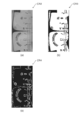
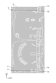
受付部11は、処理装置10に入力された画像を受け付ける。受付部11は、その画像を抽出部12へ出力する。図3(a)は、処理装置10に入力された画像の一例である。
抽出部12は、入力された画像から、計器が撮影されている領域の候補を抽出する。ここでは、撮像装置によって撮影され、処理装置10に入力された画像を、入力画像と呼ぶ。入力画像の一部であって、計器が撮影された領域の候補を、候補領域と呼ぶ。抽出部12から出力される候補領域は、複数であっても良い。
具体的な一例として、抽出部12は、輪郭抽出部12a及び選定部12bを有する。
輪郭抽出部12aは、例えば、入力画像における明度差又は輝度差に基づき、入力画像に含まれる輪郭(エッジ)を抽出する。輪郭を抽出する際に、輪郭抽出部12aは、入力画像に適宜処理を加えても良い。例えば、輪郭抽出部12aは、入力画像をグレイスケールに変換した後に二値化し、この二値画像から輪郭を抽出する。
輪郭抽出部12aは、例えば、入力画像における明度差又は輝度差に基づき、入力画像に含まれる輪郭(エッジ)を抽出する。輪郭を抽出する際に、輪郭抽出部12aは、入力画像に適宜処理を加えても良い。例えば、輪郭抽出部12aは、入力画像をグレイスケールに変換した後に二値化し、この二値画像から輪郭を抽出する。
選定部12bは、入力画像から輪郭で囲まれた領域を抽出する。例えば、選定部12bは、各領域について、ある一方向の最大長さと面積を、それぞれ予め設定された閾値と比較する。選定部12bは、最大長さ及び面積がそれぞれ閾値を超えた領域を、候補領域として選定する。これにより、面積が小さすぎる領域や、計器と形が大きく異なる領域などが除外される。図3(b)は、図3(a)に表した入力画像IIから抽出された、候補領域CR1を表している。選定部12bは、候補領域を補正部13へ出力する。
補正部13は、候補領域を適宜射影変換する。典型的には、計器の外縁又は計器の表示盤の外縁は、円形又は四角形である。候補領域が台形や平行四辺形などの場合、補正部13は、候補領域の外縁が長方形となるように、その候補領域を射影変換する。候補領域が楕円形やオーバルの場合、補正部13は、候補領域の外縁が円形となるように、その候補領域を射影変換する。射影変換により、候補領域の歪みが補正される。補正部13は、補正した候補領域を抽出部14へ出力する。
抽出部14は、候補領域から、数字領域、目盛領域、及び指針領域を抽出する。具体的には、抽出部14は、数字領域抽出部14a、種類決定部14b、目盛領域抽出部14c、及び指針領域抽出部14dを含む。
数字領域抽出部14aは、候補領域から、文字が写っている領域の候補である文字候補を抽出する。文字候補は、候補領域の一部である。文字候補には、数字、アルファベットなどが含まれる。又は、文字候補には、計器への付着物や画像のノイズなどの文字以外のものが含まれうる。文字候補の抽出には、例えば、情景文字認識技術などが用いられる。抽出される文字候補の大きさは、候補領域の大きさに基づいて決定される。
数字領域抽出部14aは、それぞれの文字候補について、以下の処理を行う。
まず、数字領域抽出部14aは、文字候補と、数字と、の照合率をそれぞれ算出する。例えば、数字領域抽出部14aは、文字候補と、予め登録された数字の画像と、の間の特徴量の類似度を、照合率として算出する。次に、数字領域抽出部14aは、文字候補を、予め設定された角度回転させる。数字領域抽出部14aは、再び、回転した文字候補と、数字と、の照合率をそれぞれ算出する。以降は、回転回数が所定の回数に達するか、合計の回転角度が所定の閾値に達するまで、文字候補の回転と照合率の算出を繰り返す。
まず、数字領域抽出部14aは、文字候補と、数字と、の照合率をそれぞれ算出する。例えば、数字領域抽出部14aは、文字候補と、予め登録された数字の画像と、の間の特徴量の類似度を、照合率として算出する。次に、数字領域抽出部14aは、文字候補を、予め設定された角度回転させる。数字領域抽出部14aは、再び、回転した文字候補と、数字と、の照合率をそれぞれ算出する。以降は、回転回数が所定の回数に達するか、合計の回転角度が所定の閾値に達するまで、文字候補の回転と照合率の算出を繰り返す。
図4(a)及び図4(b)において、横軸は、回転角度Aを表す。縦軸は、照合率Rを表す。文字候補の回転及び照合率の算出を繰り返すことで、図4(a)及び図4(b)に表したような結果が得られる。
図4(a)は、文字候補に数字が含まれる場合の結果を表す。数字領域抽出部14aは、結果から、回転角度の変化に対する照合率の変化の割合を算出する。例えば、当該割合が閾値を超えている場合、数字領域抽出部14aは、その文字候補に数字が含まれていると判断する。図4(a)の例では、数字領域抽出部14aは、網掛部分の結果から、文字候補に数字が含まれていると判断する。
図4(b)は、文字候補に数字が含まれない場合の結果を表す。文字候補に数字が含まれない場合、図4(b)に表したように、回転角度の変化に対する照合率の変化の割合が小さい。この結果に基づき、数字領域抽出部14aは、複数の文字候補から、数字を含まない文字候補を除外する。数字領域抽出部14aは、数字を含むと判断された各文字候補について、文字候補を囲む最小の範囲を決定する。
数字領域抽出部14aは、回転角度と照合率の結果に基づき、候補領域を回転させても良い。例えば、数字領域抽出部14aは、文字候補に数字が含まれると判断すると、照合率の最大値が得られた角度を記録する。数字領域抽出部14aは、全ての文字候補について判断が完了すると、それらの角度の平均値を算出する。数字領域抽出部14aは、候補領域を、算出された平均値回転させる。
以上の処理により、例えば、図3(b)に表した候補領域CR1の画像から、図3(c)に表したように、数字を囲む最小範囲が得られる。これらの最小範囲が、それぞれ候補領域CR1から数字領域R1として抽出される。数字領域抽出部14aは、抽出された複数の数字領域及び候補領域における各数字領域の位置を、種類決定部14bへ出力する。
このとき、数字領域抽出部14aから補正部13へ、数字領域に関する情報が出力されても良い。例えば、数字領域抽出部14aは、図3(c)に表したように、抽出された数字領域の少なくとも一部について、長さL1と長さL2を取得し、補正部13へ出力する。例えば、補正部13は、長さL1と長さL2の比率を基に候補領域の歪みを算出し、この歪みを補正するように候補領域を再度射影変換する。この場合、射影変換後の候補領域について、再び数字領域抽出部14aによる処理が実行される。これにより、歪みのより小さい数字領域を抽出できる。後の処理において、歪みのより小さい目盛領域及び指針領域を抽出できる。数字領域、目盛領域、及び指針領域の歪みが小さいと、計器の示度の読み取り精度を向上させることができる。
種類決定部14bは、数字領域の位置に基づき、入力画像に写っている計器の種類を決定する。例えば、図3(c)に表したように、複数の数字領域R1が周方向に湾曲して並んでいる場合、種類決定部14bは、入力画像に写っている計器が、丸型計器であると決定する。数字が一方向に沿って並んでいる場合、種類決定部14bは、入力画像に写っている計器が、縦型計器又は横型計器であると決定する。種類決定部14bは、計器の種類を目盛領域抽出部14cへ出力する。
目盛領域抽出部14cは、候補領域から目盛領域を抽出する。例えば、目盛領域抽出部14cによる処理は、種類決定部14bによる決定の結果に応じて変化する。具体的には、計器の種類が丸型と決定されると、目盛領域抽出部14cは、候補領域を極座標変換する。例えば、候補領域が円状である場合、その円の中心を極座標系の中心とする。候補領域が四角形の場合、対角線同士の交点を極座標系の中心とする。極座標系の中心を設定すると、候補領域が極座標変換される。
計器が丸型である場合、候補領域において、目盛は周方向に配列されている。極座標変換後の候補領域では、目盛が実質的に一方向に配列される。計器の種類が縦型又は横型である場合には、候補領域は極座標変換されない。縦形計器及び横型計器では、目盛が既に一方向に配列されているためである。図5(a)は、図3(b)の候補領域CR1を極座標変換した結果を表している。
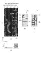
例えば、目盛領域抽出部14cは、図5(a)に表した極座標変換後の候補領域CR2を二値化する。これにより、図5(b)に表したように、二値化された候補領域CR3が得られる。目盛領域抽出部14cは、二値化された候補領域CR3から輪郭を抽出する。これにより、図5(c)に表したように、輪郭が強調された候補領域CR4が得られる。
目盛領域抽出部14cは、輪郭を抽出した画像に対して、図6(a)に表したように、複数の第1サブ領域SRAを設定する。複数の第1サブ領域SRAは、第1方向D1に配列されている。第1方向D1に垂直な第2方向D2における第1サブ領域SRAの長さは、例えば、候補領域CR4の第2方向D2における長さと同じである。例えば、設定される第1サブ領域SRAの数は、候補領域の大きさに基づいて決定される。図6(a)の例では、10個の第1サブ領域SRA1~SRA10が設定されている。
計器が丸型である場合、第1方向D1は、極座標変換前の径方向に対応する。径方向とは、計器又は目盛の回転中心から目盛に向かう方向である。第2方向D2は、周方向に対応する。周方向とは、目盛が配列された方向である。目盛領域抽出部14cは、各第1サブ領域SRAにおける横線の数をカウントする。ここでは、横線とは、第1方向D1に延びる線を指す。
図6(b)は、図6(a)に表した部分P1を拡大した画像である。図6(c)は、図6(a)に表した部分P2を拡大した画像である。ここでは、説明の便宜のため、図6(b)及び図6(c)では、図6(a)の画像の白黒を反転して表している。例えば、目盛領域抽出部14cは、図6(b)及び図6(c)に表したように、各第1サブ領域SRAにマスクMaを設定する。例えば、マスクMaで覆われていない領域の第2方向D2における長さが、規定値となるように、マスクMaが設定される。目盛領域抽出部14cは、マスクMaで覆われていない領域に輪郭が有るか確認する。輪郭が有る場合、目盛領域抽出部14cは、その輪郭の第1方向D1における長さを測定する。第1方向D1における長さが所定の閾値を超えている場合、その輪郭は横線であると判断される。例えば、図6(b)に表した例では、マスクMa同士の間の輪郭E1は横線とは判断されない。図6(c)に表した例では、マスクMa同士の間の輪郭E2及びE3が横線と判断される。目盛領域抽出部14cは、マスクMaの位置を変化させながら、各第1サブ領域SRAにおける横線の数をカウントする。
目盛領域抽出部14cは、各第1サブ領域SRAについて、横線の数を合計する。例えば、図6(a)に表した画像からは、図6(d)に表した結果が得られる。図6(d)は、第1方向D1の各点における横線の数の合計Sumを表している。目盛領域抽出部14cは、この結果から、横線の合計数が所定の閾値を超えた第1サブ領域を、計器の目盛が存在する範囲(目盛範囲)と判断する。図6(d)の例では、目盛領域抽出部14cは、網掛けで示した第1サブ領域SRA8~SRA10の位置を、目盛範囲と判断する。目盛領域抽出部14cは、この判断結果に基づき、候補領域から目盛範囲を抽出する。例えば、この処理により、図5(a)に表した画像から、図7(a)に表した目盛範囲SAが抽出される。
目盛領域抽出部14cは、例えば図7(b)に表したように、輪郭を抽出した目盛範囲SAに、複数の第2サブ領域SRBを設定する。複数の第2サブ領域SRBは、第2方向D2に配列されている。図7(b)の例では、9個の第2サブ領域SRB1~SRB9が設定されている。目盛領域抽出部14cは、上述した各第2サブ領域SRBにおける横線の数の合計算出と同様に、各第2サブ領域SRBについて、横線の数を合計する。
例えば、図7(b)に表した画像からは、図7(c)に表した結果が得られる。図7(c)は、各第2サブ領域SRBにおける横線の数の合計Sumを表している。目盛領域抽出部14cは、この結果から、横線の合計数が閾値を超えた第2サブ領域を、計器の目盛が存在する領域(目盛領域)と決定する。図7(c)の例では、目盛領域抽出部14cは、網掛けで示した第2サブ領域SRB1~SRB6及びSRB9の位置を、計器の目盛領域と決定する。目盛領域抽出部14cは、この結果に基づき、目盛範囲から目盛領域を抽出する。
以上の処理により、候補領域において、目盛が存在する領域が特定される。目盛領域抽出部14cは、この結果を基に、候補領域から目盛領域を抽出する。例えば図7(d)に表したように、数字領域抽出部14aにより回転された候補領域CR1から、目盛領域R2が抽出される。目盛領域抽出部14cは、抽出した目盛領域を指針領域抽出部14dへ出力する。
目盛領域抽出部14cは、候補領域が極座標変換されていた場合には、さらに以下の処理を実行しても良い。
目盛領域抽出部14cは、目盛領域から目盛を抽出する。例えば、目盛領域抽出部14cは、目盛領域において、第2方向D2に並ぶ横線を目盛として識別する。目盛領域抽出部14cは、図8に表したように、極座標変換後の候補領域の第1方向D1における端部と、目盛Scと、の間の距離Dをそれぞれ算出する。極座標系の中心が、実際の丸型計器の中心と一致している場合、各距離はほぼ等しくなる。距離にばらつきがある場合、極座標系の中心が、実際の丸型計器の中心と一致していないことを示す。
目盛領域抽出部14cは、目盛領域から目盛を抽出する。例えば、目盛領域抽出部14cは、目盛領域において、第2方向D2に並ぶ横線を目盛として識別する。目盛領域抽出部14cは、図8に表したように、極座標変換後の候補領域の第1方向D1における端部と、目盛Scと、の間の距離Dをそれぞれ算出する。極座標系の中心が、実際の丸型計器の中心と一致している場合、各距離はほぼ等しくなる。距離にばらつきがある場合、極座標系の中心が、実際の丸型計器の中心と一致していないことを示す。
例えば、目盛領域抽出部14cは、距離の最大値、距離の最小値、距離が最大となった横線の位置、及び距離が最小となった横線の位置を取得する。距離が最小となった位置では、実際の丸型計器の中心が、極座標系の中心よりも第1方向D1において離れた位置にある。距離が最大となった位置では、実際の丸型計器の中心が、極座標系の中心よりも第1方向D1において近い位置にある。目盛領域抽出部14cは、これらの情報に基づき、極座標系の中心を修正し、候補領域を再び極座標変換する。目盛領域抽出部14cは、新たに極座標変換された候補領域に対して、目盛領域の再度抽出する。これにより、目盛領域をより正確に抽出できる。計器の示度の読み取り精度を向上させることができる。
図5~図8では、計器が丸型の場合における目盛領域抽出部14cの処理を説明した。計器が縦型又は横型の場合も、上記と同様の処理が実行される。すなわち、目盛領域抽出部14cは、目盛が一方向に配列された候補領域に対して、複数の第1サブ領域を設定する。目盛領域抽出部14cは、各第1サブ領域における横線の合計数に基づき、候補領域から目盛範囲を抽出する。目盛領域抽出部14cは、目盛範囲に対して、複数の第2サブ領域を設定する。目盛領域抽出部14cは、各第2サブ領域における横線の合計数に基づき、目盛範囲から目盛領域を抽出する。
指針領域抽出部14dは、候補領域に、指針を検出するための検出領域を設定する。種類決定部14bにより計器が丸型と決定されていた場合、指針領域抽出部14dは、円状の指針領域を設定する。計器が縦型又は横型と決定されていた場合、指針領域抽出部14dは、四角形の指針領域を設定する。指針領域抽出部14dは、検出領域から得られる情報に基づいて、指針の位置を決定する。指針領域抽出部14dは、検出領域の大きさを変化させながら、各検出領域における指針位置の決定結果に基づいて、指針領域を抽出する。
計器が丸型である場合の指針領域抽出部14dによる処理の一例を説明する。
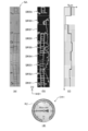
まず、指針領域抽出部14dは、円状の検出領域を設定する。この検出領域の中心は、候補領域の中心に設定される。始めに、検出領域の円の径は、予め決定された値に設定される。指針領域抽出部14dは、検出領域を極座標変換する。例えば図9(a)に表したように、円状の検出領域DR1が候補領域に設定される。図9(b)は、図9(a)に表した検出領域DR1を極座標変換し、二値化した結果を表す。指針領域抽出部14dは、極座標変換された検出領域の第2方向D2の各点において、第1方向D1に並んだ複数の画素の輝度の合計を算出する。二値化された検出領域に対してこの処理を実行すると、第2方向D2の各点において、第1方向D1に並んだ白色画素の数が算出される。図9(c)は、図9(b)に表した検出領域について、第2方向D2における位置Pと輝度の合計Sumの関係を表す。指針領域抽出部14dは、例えば、輝度の合計が最小となった第2方向D2の位置に、指針が存在すると決定する。複数の点で輝度の合計の最小値が同じ場合、指針領域抽出部14dは、輝度が最小値である位置の分布範囲と、分布範囲閾値と、を比較する。指針領域抽出部14dは、分布範囲が分布範囲閾値以下のとき、平均した位置を指針の位置とする。一例として、分布範囲閾値は、極座標系で10度の角度に対応する第2方向D2の距離が設定される。指針領域抽出部14dは、分布範囲が分布範囲閾値を超えるとき、指針の位置を未検出とする。
まず、指針領域抽出部14dは、円状の検出領域を設定する。この検出領域の中心は、候補領域の中心に設定される。始めに、検出領域の円の径は、予め決定された値に設定される。指針領域抽出部14dは、検出領域を極座標変換する。例えば図9(a)に表したように、円状の検出領域DR1が候補領域に設定される。図9(b)は、図9(a)に表した検出領域DR1を極座標変換し、二値化した結果を表す。指針領域抽出部14dは、極座標変換された検出領域の第2方向D2の各点において、第1方向D1に並んだ複数の画素の輝度の合計を算出する。二値化された検出領域に対してこの処理を実行すると、第2方向D2の各点において、第1方向D1に並んだ白色画素の数が算出される。図9(c)は、図9(b)に表した検出領域について、第2方向D2における位置Pと輝度の合計Sumの関係を表す。指針領域抽出部14dは、例えば、輝度の合計が最小となった第2方向D2の位置に、指針が存在すると決定する。複数の点で輝度の合計の最小値が同じ場合、指針領域抽出部14dは、輝度が最小値である位置の分布範囲と、分布範囲閾値と、を比較する。指針領域抽出部14dは、分布範囲が分布範囲閾値以下のとき、平均した位置を指針の位置とする。一例として、分布範囲閾値は、極座標系で10度の角度に対応する第2方向D2の距離が設定される。指針領域抽出部14dは、分布範囲が分布範囲閾値を超えるとき、指針の位置を未検出とする。
設定した検出領域における指針位置を決定すると、指針領域抽出部14dは、検出領域の大きさを変化させる。例えば、始めに小さな検出領域が設定される場合、指針領域抽出部14dは、検出領域を大きくする。図10(a)は、検出領域の別の一例を表す。図10(a)に表した検出領域DR2の径は、図9(a)に表した検出領域DR1の径よりも長い。図10(b)は、図10(a)に表した検出領域DR2を極座標変換し、二値化した結果を表す。指針領域抽出部14dは、図10(b)に表した検出領域DR2についても同様に、第2方向D2の各点において、第1方向D1に並んだ複数の画素の輝度の合計を算出する。図10(c)は、図10(b)に表した検出領域について、第2方向D2における位置Pと輝度の合計Sumの関係を表す。
指針領域抽出部14dは、上述した検出領域の大きさの変更及び検出領域における指針位置の決定を繰り返す。これらの処理は、検出領域の大きさが所定の条件を満たすまで繰り返される。例えば、検出領域が、目盛領域に達するまで繰り返される。典型的な丸型計器では、指針の少なくとも一部は、目盛領域の内側に存在する。検出領域が目盛領域に達すれば、その検出領域内には、指針の少なくとも一部が存在する。又は、検出領域の大きさが、候補領域の大きさに基づいて算出される特定の値に達するまで、上述した処理が繰り返されても良い。
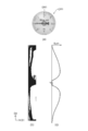
図11は、検出領域の大きさの変更及び検出領域における指針位置の決定の繰り返しにより得られた結果を表す。図11において、横軸は、検出領域の大きさSを表し、縦軸は、第2方向D2における指針の位置Pを表す。計器が丸型の場合、検出領域の大きさは、径(半径又は直径)に対応する。第2方向D2における位置は、角度に対応する。
指針領域抽出部14dは、検出領域の大きさの変化と指針位置との結果から、検出領域の大きさについて、第1範囲及び第2範囲を決定する。大きさが第1範囲内にあるとき、指針位置の変化が小さい。大きさが第2範囲内にあるとき、指針位置の変化が大きい。例えば、指針領域抽出部14dは、図11に表したグラフに関して、横軸の各点において、大きさの変化に対する指針位置の変化の割合を算出する。指針領域抽出部14dは、前記割合が第1閾値以下であり、且つ連続している部分を、第1範囲として抽出する。指針領域抽出部14dは、前記割合が第2閾値を超え、且つ連続している部分を、第2範囲として抽出する。第2閾値は、第1閾値よりも高い値である。
図11では、第1範囲Ra1及び第2範囲Ra2の一例を表している。丸型計器では、典型的には、指針の一端は目盛に近接し、指針の他端は回転中心よりも反対側に突出している。検出領域が小さいと、図9(b)及び図9(c)に表したように、指針の一端が存在する位置と他端が存在する位置の両方で輝度の合計値が大きい。このため、指針の一端を精度良く識別することが容易では無い。この結果、図11に表した第2範囲Ra2のように、指針位置の変化が大きくなる。一方で、検出領域が大きくなると、図10(b)及び図10(c)に表したように、指針の一端が存在する位置における輝度の合計が、他端が存在する位置の輝度の合計よりも大きくなる。これにより、指針の一端を、他端と判別できるようになり、指針位置の変化が小さくなる。
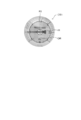
指針領域抽出部14dは、第1範囲の大きさ(径)の上限値に基づき、指針領域の大きさを決定する。指針領域抽出部14dは、さらに、第2範囲の大きさの上限値又は第1範囲の大きさ(径)の下限値に基づき、指針領域の大きさを決定しても良い。例えば、計器が丸型のとき、図12に表したように、円環状の指針領域R3が抽出される。指針領域R3の内径IRは、第2範囲の大きさの上限値又は第1範囲の大きさの下限値に基づいて設定される。指針領域R3の外径ORは、第1範囲の長さの上限値に基づいて設定される。換言すると、指針領域は、長さが第2範囲内にある検出領域を含まないように、設定される。これにより、示度の読み取りの精度を向上させることができる。
以上の処理により、候補領域から、数字領域、目盛領域、及び指針領域が抽出される。抽出部14は、抽出した各領域を読取部15へ出力する。
読取部15は、抽出部14により抽出された数字領域、目盛領域、及び指針領域を用いて、計器の示度を読み取る。
具体的には、読取部15は、目盛認識部15a、数字認識部15b、指針認識部15c、目盛接合部15d、及び算出部15eを有する。
具体的には、読取部15は、目盛認識部15a、数字認識部15b、指針認識部15c、目盛接合部15d、及び算出部15eを有する。
目盛認識部15aは、抽出部14により抽出された目盛領域において、輝度差を基に計器の目盛を認識する。例えば、目盛認識部15aは、基準線を決定し、この基準線と各目盛との間の角度を算出する。
数字認識部15bは、抽出部14により抽出された数字領域において、数字を認識する。指針認識部15cは、抽出部14により抽出された指針領域の情報に基づいて、基準線と指針との間の角度を検出する。
目盛接合部15dは、目盛認識部15aにより認識された目盛と、数字認識部15bにより認識された数字と、を対応付ける。算出部15eは、各目盛の角度、目盛と数字の対応情報、及び指針の角度に基づき、計器の示度を算出する。読取部15は、算出された示度を出力部16へ送る。
出力部16は、例えば、算出された示度に基づく情報を、外部の出力装置へ出力する。例えば、情報は、読み取った示度を含む。情報は、読み取った示度に基づいて算出された結果を含んでも良い。出力部16は、読み取った複数の示度を基に、別の値を算出し、その算出結果を出力しても良い。出力部16は、読み取った時刻などの情報をさらに出力しても良い。又は、出力部16は、読み取った示度数字及び読み取った時刻などの情報を含むファイルを、CSVなどの所定の形式で出力しても良い。出力部16は、FTP(File Transfer Protocol)などを用いて外部のサーバへデータを送信しても良い。又は、出力部16は、データベース通信を行い、ODBC(Open Database Connectivity)などを用いて外部のデータベースサーバへデータを挿入してもよい。
処理装置10は、例えば、中央演算処理装置からなる処理回路を含む。記憶装置20は、例えば、ハードディスクドライブ(HDD)、ネットワーク接続ハードディスク(NAS)、組み込み用マルチメディアカード(eMMC)、ソリッドステートドライブ(SSD)、及びソリッドステートハイブリッドドライブ(SSHD)の少なくともいずれかを備える。処理装置10と記憶装置20は、有線又は無線で接続される。又は、処理装置10と記憶装置20は、ネットワークを介して相互に接続されていても良い。
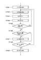
図13~図16は、第1実施形態に係る読取支援システムにおける処理を表すフローチャートである。
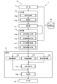
図13に表したように、受付部11は、入力された画像を受け付ける(ステップS11)。輪郭抽出部12aは、入力画像から輪郭を抽出する(ステップS12a)。選定部12bは、輪郭で囲まれた領域から、条件を満たす一部の領域を候補領域として選定する。(ステップS12b)。補正部13は、候補領域を射影変換し、補正する。(ステップS13)。数字領域抽出部14aは、候補領域から複数の数字領域を抽出する(ステップS14a)。種類決定部14bは、複数の数字領域のそれぞれの位置を基に、計器の種類を決定する(ステップS14b)。目盛領域抽出部14cは、候補領域から目盛領域を抽出する(ステップS14c)。指針領域抽出部14dは、候補領域から指針領域を抽出する(ステップS14d)。読取部15は、指針の示度を読み取る(ステップS15)。出力部16は、読み取り結果に基づく情報を出力する(ステップS16)。
図13に表したように、受付部11は、入力された画像を受け付ける(ステップS11)。輪郭抽出部12aは、入力画像から輪郭を抽出する(ステップS12a)。選定部12bは、輪郭で囲まれた領域から、条件を満たす一部の領域を候補領域として選定する。(ステップS12b)。補正部13は、候補領域を射影変換し、補正する。(ステップS13)。数字領域抽出部14aは、候補領域から複数の数字領域を抽出する(ステップS14a)。種類決定部14bは、複数の数字領域のそれぞれの位置を基に、計器の種類を決定する(ステップS14b)。目盛領域抽出部14cは、候補領域から目盛領域を抽出する(ステップS14c)。指針領域抽出部14dは、候補領域から指針領域を抽出する(ステップS14d)。読取部15は、指針の示度を読み取る(ステップS15)。出力部16は、読み取り結果に基づく情報を出力する(ステップS16)。
図14は、数字領域抽出部14aにより実行されるステップS14aの処理を具体的に表したフローチャートである。数字領域抽出部14aは、候補領域から文字候補を抽出する(ステップS14a1)。数字領域抽出部14aは、複数の文字候補の1つを回転させる(ステップS14a2)。数字領域抽出部14aは、回転させた文字候補について、照合率を算出する(ステップS14a3)。数字領域抽出部14aは、算出された照合率を記録する(ステップS14a4)。数字領域抽出部14aは、文字候補の回転回数が閾値以下か判断する(ステップS14a5)。回転回数が閾値以下のとき、ステップS14a2~S14a4が繰り返される。回転回数が閾値を超えると、数字領域抽出部14aは、照合率の変化量が閾値以下か判断する(ステップS14a6)。照合率の変化量が閾値以下のとき、ステップS14a8に進む。照合率の変化量が閾値を超えるとき、数字領域抽出部14aは、文字候補に含まれる数字を囲む最小範囲を決定する(ステップS14a7)。数字領域抽出部14aは、数字の認識を試行していない他の文字候補があるか判断する(ステップS14a8)。他の文字候補があるとき、数字領域抽出部14aは、他の文字候補について、ステップS14a2を実行する。他の文字候補がないとき、数字領域抽出部14aは、それまでに決定した最小範囲を、数字領域として候補領域から抽出する(ステップS14a9)。
図15は、目盛領域抽出部14cにより実行されるステップS14cの処理を具体的に表したフローチャートである。目盛領域抽出部14cは、種類決定部14bにより決定された計器の種類を参照し、計器が丸型か判断する(ステップS14c1)。計器が丸型ではないとき、ステップS14c3に進む。計器が丸型のとき、目盛領域抽出部14cは、候補領域を極座標変換する(ステップS14c2)。目盛領域抽出部14cは、候補領域に対して、複数のサブ領域列を設定する(ステップS14c3)。目盛領域抽出部14cは、候補領域に含まれる横線を検出する(ステップS14c4)。目盛領域抽出部14cは、サブ領域列における横線の数の合計を算出する(ステップS14c5)。目盛領域抽出部14cは、ステップS14c6及びS14c7を実行しても良い。目盛領域抽出部14cは、横線の数の合計の最大値をスコアとし、そのスコアが閾値を超えるか判断する(ステップS14c7)。スコアが閾値以下のとき、横線が適切に検出できていない可能性がある。目盛領域抽出部14cは、横線の検出条件を変更し、ステップS14c4を再度実行する。
スコアが閾値を超えるとき、目盛領域抽出部14cは、分解能が閾値以下か判断する(ステップS14c8)。分解能は、例えば、抽出領域の全体の大きさに対する1つの第1サブ領域の大きさの割合で表される。分解能が閾値を超えるのとき、目盛領域抽出部14cは、第1サブ領域の設定条件を変更し、ステップS14c3を再度実行する。分解能が閾値以下のとき、目盛領域抽出部14cは、各第1サブ領域における横線の数の合計に基づき、候補領域から目盛範囲を抽出する(ステップS14c8)。
目盛領域抽出部14cは、目盛範囲に対して、複数の第2サブ領域を設定する(ステップS14c9)。目盛領域抽出部14cは、目盛範囲に含まれる横線を検出する(ステップS14c10)。目盛領域抽出部14cは、第2サブ領域における横線の数の合計を算出する(ステップS14c11)。目盛領域抽出部14cは、ステップS14c12及びS14c13を実行しても良い。目盛領域抽出部14cは、横線の数の合計の最大値をスコアとし、そのスコアが閾値を超えるか判断する(ステップS14c12)。スコアが閾値以下のとき、横線が適切に検出できていない可能性がある。目盛領域抽出部14cは、横線の検出条件を変更し、ステップS14c10を再度実行する。スコアが閾値を超えるとき、目盛領域抽出部14cは、分解能が閾値以下か判断する(ステップS14c13)。分解能が閾値を超えるとき、目盛領域抽出部14cは、第2サブ領域の設定条件を変更し、ステップS14c9を再度実行する。分解能が閾値以下のとき、目盛領域抽出部14cは、各第2サブ領域における横線の数の合計に基づき、目盛範囲から目盛領域を抽出する(ステップS14c14)。
図16は、指針領域抽出部14dにより実行されるステップS14dの処理を具体的に表したフローチャートである。指針領域抽出部14dは、候補領域に検出領域を設定する(ステップS14d1)。指針領域抽出部14dは、設定した検出領域における指針の位置を決定する(ステップS14d2)。指針領域抽出部14dは、決定した指針の位置を記録する(ステップS14d3)。指針領域抽出部14dは、検出領域が条件を満たすか判断する(ステップS14d4)。例えば、指針領域抽出部14dは、検出領域が目盛領域に達しているか(重なっているか)判断する。検出領域が条件を満たさないとき、指針領域抽出部14dは、検出領域の特定の方向における長さを変更する(ステップS14d5)。長さを変更した検出領域に基づいて、指針領域抽出部14dは、ステップS14d2を再度実行する。検出領域が条件を満たすとき、指針領域抽出部14dは、長さの変化と指針位置の変化との関係に基づき、候補領域から指針領域を抽出する(ステップS14d6)。
第1実施形態の効果を説明する。
計器の示度を画像から読み取る際、画像には計器の種類に応じた処理が実行される。図2(a)~図2(d)に表したように、計器の種類に応じて目盛の配置が異なるためである。計器の種類に応じた処理を実行することで、示度の読み取りの精度を向上させることができる。
計器の種類に応じた処理を実行するために、例えば、撮影される計器の種類を予め登録する方法が考えられる。処理装置10は、登録された計器の種類を参照し、実行する処理を決定する。しかし、この方法では、計器の種類が予め登録されなければ、示度を適切に読み取ることができない。互いに異なる複数の計器の画像から示度を順次読み取る場合などは、画像に写っている計器と計器の種類をそれぞれ対応付ける必要があり、事前の設定に長い時間を要する。
計器の示度を画像から読み取る際、画像には計器の種類に応じた処理が実行される。図2(a)~図2(d)に表したように、計器の種類に応じて目盛の配置が異なるためである。計器の種類に応じた処理を実行することで、示度の読み取りの精度を向上させることができる。
計器の種類に応じた処理を実行するために、例えば、撮影される計器の種類を予め登録する方法が考えられる。処理装置10は、登録された計器の種類を参照し、実行する処理を決定する。しかし、この方法では、計器の種類が予め登録されなければ、示度を適切に読み取ることができない。互いに異なる複数の計器の画像から示度を順次読み取る場合などは、画像に写っている計器と計器の種類をそれぞれ対応付ける必要があり、事前の設定に長い時間を要する。
第1実施形態に係る読取支援システム1では、まず、数字領域抽出部14aが、計器の複数の数字を含む数字領域を候補領域から抽出する。そして、種類決定部14bが、複数の数字領域の位置に基づいて計器の種類を決定する。すなわち、第1実施形態に係る読取支援システム1によれば、計器の種類が画像から自動で決定される。読取支援システム1を用いることで、示度の読み取りにおいて、ユーザは予め計器の種類を登録する必要が無くなる。
第1実施形態の別の効果を説明する。
計器の示度を画像から読み取る際には、候補領域から、数字領域、目盛領域、及び指針領域の抽出が行われる。そして、抽出されたこれらの領域に基づいて、計器の示度が読み取られる。このとき、数字領域、目盛領域、又は指針領域がより適切に抽出されることが望ましい。数字領域、目盛領域、又は指針領域がより適切に抽出されることで、示度をより精度良く読み取ることが可能となる。
例えば、計器において目盛が存在する位置を予め登録し、この登録情報と画像における輝度を基に、候補領域から目盛領域を抽出する方法がある。しかし、この方法では、実際の目盛領域が登録された位置と異なる場合には、目盛領域を適切に抽出できない。互いに異なる複数の計器の画像から示度を順次読み取る場合などは、画像に写っている計器とその計器における目盛の位置をそれぞれ対応付ける必要があり、事前の設定に長い時間を要する。
計器の示度を画像から読み取る際には、候補領域から、数字領域、目盛領域、及び指針領域の抽出が行われる。そして、抽出されたこれらの領域に基づいて、計器の示度が読み取られる。このとき、数字領域、目盛領域、又は指針領域がより適切に抽出されることが望ましい。数字領域、目盛領域、又は指針領域がより適切に抽出されることで、示度をより精度良く読み取ることが可能となる。
例えば、計器において目盛が存在する位置を予め登録し、この登録情報と画像における輝度を基に、候補領域から目盛領域を抽出する方法がある。しかし、この方法では、実際の目盛領域が登録された位置と異なる場合には、目盛領域を適切に抽出できない。互いに異なる複数の計器の画像から示度を順次読み取る場合などは、画像に写っている計器とその計器における目盛の位置をそれぞれ対応付ける必要があり、事前の設定に長い時間を要する。
第1実施形態に係る読取支援システム1では、目盛領域抽出部14cが、以下の処理を実行する。
目盛領域抽出部14cは、候補領域に対して、第1方向に並んだ複数の第1サブ領域を、第2方向において複数設定する。目盛領域抽出部14cは、それぞれの第1サブ領域において第2方向に延びる線分の数を検出する。目盛領域抽出部14cは、検出された線分の数に基づいて、候補領域の第2方向における一部を、計器の目盛が存在する目盛範囲として抽出する。
これらの処理によれば、計器における目盛領域の位置の事前登録を必要とせずに、候補領域から、目盛が存在する範囲をより適切に抽出できる。このため、示度の読み取りにおいて、ユーザは予め計器の目盛の位置を登録する必要が無くなる。目盛範囲がより適切に抽出されることで、この目盛範囲を用いた示度の読み取りの精度を向上させることができる。
目盛領域抽出部14cは、候補領域に対して、第1方向に並んだ複数の第1サブ領域を、第2方向において複数設定する。目盛領域抽出部14cは、それぞれの第1サブ領域において第2方向に延びる線分の数を検出する。目盛領域抽出部14cは、検出された線分の数に基づいて、候補領域の第2方向における一部を、計器の目盛が存在する目盛範囲として抽出する。
これらの処理によれば、計器における目盛領域の位置の事前登録を必要とせずに、候補領域から、目盛が存在する範囲をより適切に抽出できる。このため、示度の読み取りにおいて、ユーザは予め計器の目盛の位置を登録する必要が無くなる。目盛範囲がより適切に抽出されることで、この目盛範囲を用いた示度の読み取りの精度を向上させることができる。
読取支援システム1では、目盛領域抽出部14cが、さらに以下の処理を実行する。
目盛領域抽出部14cは、目盛範囲に対して、第2方向に並んだ複数の第2サブ領域を、第1方向において複数設定する。目盛領域抽出部14cは、それぞれの第2サブ領域において第2方向に延びる線分の数を検出する。目盛領域抽出部14cは、検出された線分の数に基づいて、目盛範囲の第1方向における一部を、計器の目盛が存在する目盛領域として抽出する。
目盛範囲を抽出した後にこれらの処理を実行することで、目盛範囲から目盛が存在する領域をより高精度に抽出できる。例えば、この目盛領域を示度の読み取りに用いることで、読み取りの精度を向上させることができる。
目盛領域抽出部14cは、目盛範囲に対して、第2方向に並んだ複数の第2サブ領域を、第1方向において複数設定する。目盛領域抽出部14cは、それぞれの第2サブ領域において第2方向に延びる線分の数を検出する。目盛領域抽出部14cは、検出された線分の数に基づいて、目盛範囲の第1方向における一部を、計器の目盛が存在する目盛領域として抽出する。
目盛範囲を抽出した後にこれらの処理を実行することで、目盛範囲から目盛が存在する領域をより高精度に抽出できる。例えば、この目盛領域を示度の読み取りに用いることで、読み取りの精度を向上させることができる。
第1実施形態に係る読取支援システム1では、指針領域抽出部14dが、以下の処理を実行する。
指針領域抽出部14dは、計器の種類が丸型である場合、候補領域に対して、計器の指針を検出するための円状の検出領域を設定する。指針領域抽出部14dは、検出領域の大きさを変化させながら、それぞれの大きさの検出領域において指針の角度を決定し、決定の結果に基づいて候補領域から指針が存在する指針領域を抽出する。これらの処理によれば、計器における指針領域の位置の事前登録を必要とせずに、候補領域から指針領域をより適切に抽出できる。
指針領域抽出部14dは、計器の種類が丸型である場合、候補領域に対して、計器の指針を検出するための円状の検出領域を設定する。指針領域抽出部14dは、検出領域の大きさを変化させながら、それぞれの大きさの検出領域において指針の角度を決定し、決定の結果に基づいて候補領域から指針が存在する指針領域を抽出する。これらの処理によれば、計器における指針領域の位置の事前登録を必要とせずに、候補領域から指針領域をより適切に抽出できる。
特に、指針領域抽出部14dは、大きさの変化に対する角度の変化の結果から、大きさについて、第1範囲及び第2範囲を決定する。そして、指針領域抽出部14dは、第1範囲の上限値に基づく外径と、第2範囲の上限値に基づく内径と、を有する円環状の指針領域を抽出する。この処理によれば、指針の認識への寄与が小さい領域を指針領域から除外できる。この処理により抽出された指針領域を示度の読み取りに用いることで、読み取りの精度を向上させることができる。
(第2実施形態)
図17は、第2実施形態に係る読取支援システムの構成を表すブロック図である。
第2実施形態に係る読取支援システム2は、撮像装置30をさらに備える。撮像装置30は、計器を撮影し、画像を生成する。撮像装置30は、生成した画像を処理装置10へ送信する。又は、撮像装置30は、画像を記憶装置20に記憶しても良い。処理装置10は、記憶装置20にアクセスし、記憶された画像を参照する。撮像装置30が動画を取得する場合、撮像装置30は、その動画から静止画像を取り出して処理装置10に送信する。撮像装置30は、例えばカメラを含む。
図17は、第2実施形態に係る読取支援システムの構成を表すブロック図である。
第2実施形態に係る読取支援システム2は、撮像装置30をさらに備える。撮像装置30は、計器を撮影し、画像を生成する。撮像装置30は、生成した画像を処理装置10へ送信する。又は、撮像装置30は、画像を記憶装置20に記憶しても良い。処理装置10は、記憶装置20にアクセスし、記憶された画像を参照する。撮像装置30が動画を取得する場合、撮像装置30は、その動画から静止画像を取り出して処理装置10に送信する。撮像装置30は、例えばカメラを含む。
処理装置10は、識別して読み取った文字に基づく情報を出力装置40へ送信する。出力装置40は、処理装置10から受信した情報を、ユーザが認識できるように出力する。出力装置40は、例えば、モニタ、プリンタ、及びスピーカの少なくともいずれかを含む。
処理装置10、記憶装置20、撮像装置30、及び出力装置40は、例えば、有線又は無線で相互に接続される。又は、これらはネットワークを介して相互に接続されていても良い。又は、処理装置10、記憶装置20、撮像装置30、及び出力装置40の少なくとも2つ以上が、1つの装置に組み込まれていても良い。例えば、処理装置10が、撮像装置30の画像処理部などと一体に組み込まれていても良い。
(第3実施形態)
図18は、第3実施形態に係る読取支援システムの構成を表すブロック図である。
第3実施形態に係る読取支援システム3は、移動体50をさらに備える。移動体50は、所定のエリア内を移動する。移動体50が移動するエリア内には、計器が設けられている。移動体50は、例えば、無人搬送車(AGV)である。移動体50は、ドローンなどの飛翔体であっても良い。移動体50は、自立歩行するロボットであっても良い。移動体50は、無人で所定の作業を行うフォークリフトやクレーンなどであっても良い。
図18は、第3実施形態に係る読取支援システムの構成を表すブロック図である。
第3実施形態に係る読取支援システム3は、移動体50をさらに備える。移動体50は、所定のエリア内を移動する。移動体50が移動するエリア内には、計器が設けられている。移動体50は、例えば、無人搬送車(AGV)である。移動体50は、ドローンなどの飛翔体であっても良い。移動体50は、自立歩行するロボットであっても良い。移動体50は、無人で所定の作業を行うフォークリフトやクレーンなどであっても良い。
例えば、処理装置10及び撮像装置30は、移動体50に搭載される。処理装置10は、移動体50とは別に設けられ、移動体50とネットワークを介して接続されても良い。移動体50が計器を撮影可能な位置に移動したとき、撮像装置30は、計器を撮影し、画像を生成する。
図18に表したように、読取支援システム3は、取得装置60をさらに備えても良い。取得装置60は、移動体50に搭載される。例えば、計器に対応して、固有の識別情報を有する識別体が設けられる。取得装置60は、識別体が有する識別情報を取得する。
図18に表したように、読取支援システム3は、制御装置70をさらに備えても良い。制御装置70は、移動体50を制御する。移動体50は、制御装置70から送信される指令に基づいて、所定のエリア内を移動する。制御装置70は、移動体50に搭載されても良いし、移動体50とは別に設けられても良い。制御装置70は、例えば、中央演算処理装置からなる処理回路を含む。1つの処理回路が、処理装置10及び制御装置70の両方として機能しても良い。
例えば、識別体は、ID情報を有するradio frequency(RF)タグである。識別体は、ID情報を含む電磁界又は電波を発する。取得装置60は、識別体から発せられた電磁界又は電波を受信し、ID情報を取得する。
又は、識別体は、1次元又は2次元のバーコードであっても良い。取得装置60は、バーコードリーダである。取得装置60は、バーコードを読み取ることで、そのバーコードが有する識別情報を取得する。
図18に表したように、処理装置10は、紐付部17をさらに含んでも良い。例えば、取得装置60は、識別情報を取得すると、処理装置10に送信する。紐付部17は、送信された識別情報と、読み取った文字と、を紐付ける。紐付けた情報は、記憶装置20に記憶される。
図19は、第3実施形態に係る読取支援システムの動作を説明する模式図である。
例えば、移動体50は、所定の軌道Tに沿って移動する移動体である。移動体50には、撮像装置30及び取得装置60が搭載されている。処理装置10は、移動体50に搭載されても良いし、移動体50とは別に設けられても良い。軌道Tは、移動体50が、計器M11及びM12の前を通過するように設けられている。
例えば、移動体50は、所定の軌道Tに沿って移動する移動体である。移動体50には、撮像装置30及び取得装置60が搭載されている。処理装置10は、移動体50に搭載されても良いし、移動体50とは別に設けられても良い。軌道Tは、移動体50が、計器M11及びM12の前を通過するように設けられている。
例えば、移動体50は、軌道Tに沿って移動し、撮像装置30により計器M11又はM12を撮影可能な位置に着くと、減速又は停止する。例えば、移動体50は、減速又は停止すると、撮像装置30に撮像の指令を送信する。又は、制御装置70から撮像装置30へ撮像の指令が送信されても良い。撮像装置30は、指令を受信すると、移動体50が減速又は停止している間に、計器M11又はM12を撮影する。
又は、移動体50は、撮像装置30が計器M11又はM12をぶれずに撮影できる程度の速度で軌道Tに沿って移動する。撮像装置30により計器M11又はM12を撮影可能な位置に着くと、移動体50又は上記制御装置から撮像の指令が送信される。撮像装置30は、指令を受信すると、計器M11又はM12を撮影する。撮像装置30は、撮影して画像を生成すると、移動体50に搭載された又は移動体50とは別に設けられた処理装置10へ、画像を送信する。
計器M11近傍には、識別体ID1が設けられている。計器M12近傍には、識別体ID2が設けられている。例えば、取得装置60は、移動体50が減速又は停止している間に、識別体ID1又はID2の識別情報を取得する。
例えば、移動体50が計器M11の前に移動する。撮像装置30は、計器M11を撮影し、画像を生成する。処理装置10は、この画像から、計器M11に表示された文字を識別する。取得装置60は、計器M11に対応する識別体ID1の識別情報を取得する。処理装置10は、識別された文字と、識別情報と、を紐付ける。
処理装置10による処理は、図19に表したように、撮像装置30が移動体50に搭載され、複数の計器を順次撮影する場合に、特に好適である。数字領域抽出部14a及び種類決定部14bにより、計器の種類が自動で決定されるため、ユーザは予め計器の種類を登録する必要が無い。
移動体50の状態に応じて、撮影された画像にばらつきが生じる可能性もある。処理装置10による処理によれば、画像にばらつきがある亜倍でも、数字領域抽出部14a、目盛領域抽出部14c、及び指針領域抽出部14dにより、候補領域から、数字領域、目盛領域、及び指針領域が自動で抽出される。このため、示度の読み取りの精度を向上させることができる。
移動体50の状態に応じて、撮影された画像にばらつきが生じる可能性もある。処理装置10による処理によれば、画像にばらつきがある亜倍でも、数字領域抽出部14a、目盛領域抽出部14c、及び指針領域抽出部14dにより、候補領域から、数字領域、目盛領域、及び指針領域が自動で抽出される。このため、示度の読み取りの精度を向上させることができる。
図20は、実施形態に係る読取支援システムのハードウェア構成を表すブロック図である。
例えば、読取支援システム1~3の処理装置10は、コンピュータであり、ROM(Read Only Memory)10a、RAM(Random Access Memory)10b、CPU(Central Processing Unit)10c、およびHDD(Hard Disk Drive)10dを有する。
例えば、読取支援システム1~3の処理装置10は、コンピュータであり、ROM(Read Only Memory)10a、RAM(Random Access Memory)10b、CPU(Central Processing Unit)10c、およびHDD(Hard Disk Drive)10dを有する。
ROM10aは、コンピュータの動作を制御するプログラムを格納している。ROM10aには、コンピュータを、制御部10として機能させるために必要なプログラムが格納されている。
RAM10bは、ROM10aに格納されたプログラムが展開される記憶領域として機能する。CPU10cは、処理回路を含む。CPU10cは、ROM10aに格納された制御プログラムを読み込み、当該制御プログラムに従ってコンピュータの動作を制御する。CPU10cは、コンピュータの動作によって得られた様々なデータをRAM10bに展開する。HDD10dは、読み取りに必要な情報や、読み取りの過程で得られた情報を記憶する。HDD10dは、例えば、図1に表した記憶装置20として機能する。
制御部10は、HDD10dに代えて、eMMC(embedded Multi Media Card)、SSD(Solid State Drive)、SSHD(Solid State Hybrid Drive)などを有していても良い。
制御部10には、入力装置10e及び出力装置10fが接続されても良い。入力装置10eは、制御部10へユーザが情報を入力するために用いられる。入力装置10eは、マイク、キーボード、マウス(音声入力)、及びタッチパッドの少なくともいずれかを含む。出力装置10fには、制御部10から送信された情報が出力される。出力装置10fは、モニタ、スピーカ、プリンタ、及びプロジェクタの少なくともいずれかを含む。タッチパネルのように、入力装置10eと出力装置10fの両方の機能を備えた機器が用いられても良い。
読取支援システム3における制御装置70にも、図20と同様のハードウェア構成を適用できる。又は、読取支援システム3において、1つのコンピュータが処理装置10及び制御装置70として機能しても良い。処理装置10及び制御装置70のそれぞれの処理及び機能は、より多くのコンピュータによる協働によって実現されても良い。
以上で説明した実施形態に係る読取支援システム、読取支援方法、及び移動体を用いることで、計器に表示された数字を、より高精度に読み取ることが可能となる。同様に、コンピュータを、読取支援システムとして動作させるためのプログラムを用いることで、計器に表示された数字を、より高精度にコンピュータに読み取らせることが可能となる。
上記の種々のデータの処理は、例えば、プログラム(ソフトウェア)に基づいて実行される。例えば、コンピュータが、このプログラムを記憶し、このプログラムを読み出すことにより、上記の種々の情報の処理が行われる。
上記の種々の情報の処理は、コンピュータに実行させることのできるプログラムとして、磁気ディスク(フレキシブルディスク及びハードディスクなど)、光ディスク(CD-ROM、CD-R、CD-RW、DVD-ROM、DVD±R、DVD±RWなど)、半導体メモリ、または、他の記録媒体に記録されても良い。
例えば、記録媒体に記録された情報は、コンピュータ(または組み込みシステム)により読み出されることが可能である。記録媒体において、記録形式(記憶形式)は任意である。例えば、コンピュータは、記録媒体からプログラムを読み出し、このプログラムに基づいてプログラムに記述されている指示をCPUで実行させる。コンピュータにおいて、プログラムの取得(または読み出し)は、ネットワークを通じて行われても良い。
実施形態に係る処理装置及び制御装置は、1つまたは複数の装置(例えばパーソナルコンピュータなど)を含む。実施形態に係る処理装置及び制御装置は、ネットワークにより接続された複数の装置を含んでも良い。
以上、本発明のいくつかの実施形態を例示したが、これらの実施形態は、例として提示したものであり、発明の範囲を限定することは意図していない。これら新規な実施形態は、その他の様々な形態で実施されることが可能であり、発明の要旨を逸脱しない範囲で、種々の省略、置き換え、変更などを行うことができる。これら実施形態やその変形例は、発明の範囲や要旨に含まれるとともに、請求の範囲に記載された発明とその均等の範囲に含まれる。また、前述の各実施形態は、相互に組み合わせて実施することができる。
Claims (24)
- 計器が撮影された領域の候補である候補領域から、前記計器の複数の数字をそれぞれ含む複数の数字領域を抽出する数字領域抽出部と、
前記複数の数字領域の位置に基づき前記計器の種類を決定する種類決定部と、
を含む処理装置を備えた読取支援システム。 - 前記数字領域抽出部は、
前記候補領域から複数の文字を抽出し、
前記複数の文字を回転させながら、前記複数の文字と数字との間の照合率をそれぞれ算出し、
前記照合率が所定の閾値以上となった前記複数の文字の少なくとも一部を、前記計器の複数の数字領域として抽出する、
請求項1記載の読取支援システム。 - 前記種類決定部は、前記複数の数字が湾曲して並んでいるとき、前記計器の種類を丸型と判断し、前記複数の数字が一方向に沿って並んでいるとき、前記計器の種類を縦型又は横型と判断する請求項1又は2に記載の読取支援システム。
- 前記処理装置は、
前記候補領域に対して、第1方向に並んだ複数の第1サブ領域を含むサブ領域列を、前記第1方向に垂直な第2方向において複数設定し、
それぞれの前記第1サブ領域において前記第2方向に延びる線分の数を検出し、
検出された前記線分の数に基づいて、前記候補領域の前記第2方向における一部を、前記計器の目盛が存在する目盛範囲として抽出する、
目盛領域抽出部をさらに含む請求項1~3のいずれか1つに記載の読取支援システム。 - 前記目盛領域抽出部は、
前記目盛範囲に対して、前記第2方向に並んだ複数の第2サブ領域を含むサブ領域行を、前記第1方向において複数設定し、
それぞれの前記第2サブ領域において前記第2方向に延びる線分の数を検出し、
検出された前記線分の数に基づいて、前記目盛範囲の前記第1方向における一部を、前記計器の目盛が存在する目盛領域として抽出する、
請求項4記載の読取支援システム。 - 前記候補領域を射影変換する補正部をさらに備え、
前記数字領域抽出部は、射影変換された前記候補領域から前記数字領域を抽出し、
前記目盛領域抽出部は、射影変換された前記候補領域から前記目盛領域を抽出する、
請求項4又は5に記載の読取支援システム。 - 前記数字領域抽出部は、前記複数の数字領域の位置を前記補正部へ出力し、
前記補正部は、前記複数の数字領域の位置に基づいて前記候補領域を再び射影変換し、
前記数字領域抽出部は、再度射影変換された前記候補領域から前記数字領域を抽出し、
前記目盛領域抽出部は、再度射影変換された前記候補領域から前記目盛領域を抽出する、
請求項4~6のいずれか1つに記載の読取支援システム。 - 前記目盛領域抽出部は、前記計器の種類が丸型である場合、前記候補領域を極座標変換し、極座標変換された前記候補領域から前記目盛範囲及び前記目盛領域を抽出する請求項4~6のいずれか1つに記載の読取支援システム。
- 前記目盛領域抽出部は、
前記目盛範囲又は前記目盛領域における前記計器の目盛を用いて、前記極座系の中心を前記計器の中心に近づけるよう補正し、
補正された前記極座系の中心に基づいて前記候補領域を再度極座標変換し、再度極座標変換された前記候補領域から前記目盛範囲及び前記目盛領域を抽出する、
請求項8記載の読取支援システム。 - 前記処理装置は、抽出された前記数字領域及び前記目盛領域に基づいて前記計器の示度を読み取る読取部をさらに含む請求項4~9のいずれか1つに記載の読取支援システム。
- 前記処理装置は、
前記計器の種類が丸型である場合、前記候補領域に対して、前記計器の指針を検出するための円状の検出領域を設定し、
前記検出領域の大きさを変化させながら、それぞれの大きさの前記検出領域において前記指針の角度を決定し、前記大きさの変化に対する前記角度の変化の結果に基づいて前記候補領域から前記指針が存在する指針領域を抽出する、
指針領域検出部をさらに含む請求項1~9のいずれか1つに記載の読取支援システム。 - 前記指針領域検出部は、
前記大きさの変化に対する前記角度の変化の結果から、前記大きさについて、前記角度の変化が第1閾値以下である第1範囲と、前記角度の変化が前記第1閾値よりも高い第2閾値以上である第2範囲と、を決定し、
前記第1範囲の上限値に基づく外径と、前記第2範囲の上限値に基づく内径と、を有する円環状の前記指針領域を抽出する、
請求項11記載の読取支援システム。 - 計器が撮影された領域の候補である候補領域に対して、第1方向に並んだ複数の第1サブ領域を含むサブ領域列を、前記第1方向に垂直な第2方向において複数設定し、
それぞれの前記第1サブ領域において前記第2方向に延びる線分の数を検出し、
検出された前記線分の数に基づいて、前記候補領域の前記第2方向における一部を、前記計器の目盛が存在する目盛範囲として抽出する、
目盛領域抽出部を含む処理装置を備えた読取支援システム。 - 前記目盛領域抽出部は、
前記目盛範囲に、前記第2方向に並んだ複数の第2サブ領域を含むサブ領域行を、前記第1方向において複数設定し、
それぞれの前記第2サブ領域において前記第2方向に延びる線分の数を検出し、
検出された前記線分の数に基づいて、前記目盛範囲の前記第1方向における一部を、前記計器の目盛が存在する目盛領域として抽出する、
請求項13記載の読取支援システム。 - 前記計器を撮影し、前記候補領域を含む画像を取得する撮像装置をさらに備えた請求項1~14のいずれか1つに記載の読取支援システム。
- 前記撮像装置が搭載され、所定のエリア内を移動する移動体をさらに備えた請求項15記載の読取支援システム。
- 計器を撮影し、画像を取得する撮像装置と、
前記画像が入力される処理装置であって、
前記画像から計器が撮影された領域の候補である候補領域を抽出する抽出部と、
前記候補領域から前記計器の複数の数字が位置する数字領域を抽出する数字領域抽出部と、
前記複数の数字領域の位置に基づき前記計器の種類を決定する種類決定部と、
を含む、前記処理装置と、
を備えた所定のエリア内を移動する移動体。 - 計器を撮影し、画像を取得する撮像装置と、
前記画像が入力される処理装置であって、
前記画像から計器が撮影された領域の候補である候補領域を抽出する抽出部と、
計器が撮影された領域の候補である候補領域に対して、第1方向に並んだ複数のサブ領域を含むサブ領域列を、前記第1方向に垂直な第2方向において複数設定し、それぞれの前記サブ領域において前記第2方向に延びる線分の数を検出し、検出された前記線分の数に基づいて、前記候補領域の前記第2方向における一部を、前記計器の目盛が存在する目盛範囲として抽出する、目盛領域抽出部と、
を含む、前記処理装置と、
を備えた所定のエリア内を移動する移動体。 - 前記目盛領域抽出部は、
前記目盛範囲に、前記第2方向に並んだ複数の第2サブ領域を含むサブ領域行を、前記第1方向において複数設定し、
それぞれの前記第2サブ領域において前記第2方向に延びる線分の数を検出し、
検出された前記線分の数に基づいて、前記目盛範囲の前記第1方向における一部を、前記計器の目盛が存在する目盛領域として抽出する、
請求項18記載の移動体。 - 計器が撮影された領域の候補である候補領域から、前記候補領域から複数の文字を抽出し、
前記複数の文字を回転させながら、前記複数の文字と数字との間の照合率をそれぞれ算出し、
前記照合率が所定の閾値以上となった前記複数の文字の少なくとも一部を前記計器の複数の数字と判断し、
前記候補領域から前記複数の数字をそれぞれ含む複数の数字領域を抽出し、
前記複数の数字領域の位置に基づき前記計器の種類を決定する、
読取支援方法。 - 計器が撮影された領域の候補である候補領域に対して、第1方向に並んだ複数の第1サブ領域を含むサブ領域列を、前記第1方向に垂直な第2方向において複数設定し、
それぞれの前記第1サブ領域において前記第2方向に延びる線分の数を検出し、
検出された前記線分の数に基づいて、前記候補領域の前記第2方向における一部を、前記計器の目盛が存在する目盛範囲として抽出する、
読取支援方法。 - 処理装置を、
計器が撮影された領域の候補である候補領域から、前記計器の複数の数字をそれぞれ含む複数の数字領域を抽出する数字領域抽出部、及び
前記複数の数字領域の位置に基づき前記計器の種類を決定する種類決定部、
として機能させるプログラム。 - 処理装置を、
計器が撮影された領域の候補である候補領域に対して、第1方向に並んだ複数の第1サブ領域を含むサブ領域列を、前記第1方向に垂直な第2方向において複数設定し、
それぞれの前記第1サブ領域において前記第2方向に延びる線分の数を検出し、
検出された前記線分の数に基づいて、前記候補領域の前記第2方向における一部を、前記計器の目盛が存在する目盛範囲として抽出する、
目盛領域抽出部として機能させるプログラム。 - 請求項22又は23に記載のプログラムを記憶した記憶媒体。
Priority Applications (3)
| Application Number | Priority Date | Filing Date | Title |
|---|---|---|---|
| CN201980060222.3A CN112703538B (zh) | 2018-12-12 | 2019-09-24 | 读取辅助系统、移动体、读取辅助方法、程序以及存储介质 |
| US17/197,343 US11468666B2 (en) | 2018-12-12 | 2021-03-10 | Reading support system and moving body |
| US17/929,468 US11861893B2 (en) | 2018-12-12 | 2022-09-02 | Reading support system and moving body |
Applications Claiming Priority (2)
| Application Number | Priority Date | Filing Date | Title |
|---|---|---|---|
| JP2018-232730 | 2018-12-12 | ||
| JP2018232730A JP6818002B2 (ja) | 2018-12-12 | 2018-12-12 | 読取支援システム、移動体、読取支援方法、プログラム、及び記憶媒体 |
Related Child Applications (1)
| Application Number | Title | Priority Date | Filing Date |
|---|---|---|---|
| US17/197,343 Continuation US11468666B2 (en) | 2018-12-12 | 2021-03-10 | Reading support system and moving body |
Publications (1)
| Publication Number | Publication Date |
|---|---|
| WO2020121622A1 true WO2020121622A1 (ja) | 2020-06-18 |
Family
ID=71077211
Family Applications (1)
| Application Number | Title | Priority Date | Filing Date |
|---|---|---|---|
| PCT/JP2019/037258 Ceased WO2020121622A1 (ja) | 2018-12-12 | 2019-09-24 | 読取支援システム、移動体、読取支援方法、プログラム、及び記憶媒体 |
Country Status (4)
| Country | Link |
|---|---|
| US (2) | US11468666B2 (ja) |
| JP (1) | JP6818002B2 (ja) |
| CN (1) | CN112703538B (ja) |
| WO (1) | WO2020121622A1 (ja) |
Families Citing this family (10)
| Publication number | Priority date | Publication date | Assignee | Title |
|---|---|---|---|---|
| JP6609345B2 (ja) | 2018-04-27 | 2019-11-20 | 株式会社東芝 | 読取システム、読取方法、プログラム、及び記憶媒体 |
| JP6818002B2 (ja) * | 2018-12-12 | 2021-01-20 | 株式会社東芝 | 読取支援システム、移動体、読取支援方法、プログラム、及び記憶媒体 |
| JP7552048B2 (ja) * | 2020-03-25 | 2024-09-18 | 日本電気株式会社 | 画像処理装置、画像処理方法、プログラム |
| JP7206236B2 (ja) * | 2020-06-26 | 2023-01-17 | 三菱重工業株式会社 | 指示値読取システムおよび方法並びにプログラム |
| KR20220055969A (ko) * | 2020-10-27 | 2022-05-04 | 삼성에스디에스 주식회사 | 비표준 사용자 인터페이스 객체 식별 시스템 및 방법 |
| JP2023010338A (ja) * | 2021-07-09 | 2023-01-20 | 株式会社東芝 | 情報処理装置およびコンピュータプログラム |
| US11948289B2 (en) * | 2021-07-19 | 2024-04-02 | Verizon Patent And Licensing Inc. | Systems and methods for precisely and accurately identifying a meter reading from an analog meter using image processing techniques |
| JP7702208B2 (ja) * | 2022-01-31 | 2025-07-03 | 株式会社東芝 | プログラム、情報処理装置、および情報処理方法 |
| JP7776721B2 (ja) * | 2024-03-28 | 2025-11-27 | 株式会社エクサウィザーズ | 情報処理方法、プログラム及び情報処理システム |
| CN119251815B (zh) * | 2024-09-24 | 2026-02-17 | 成都飞机工业(集团)有限责任公司 | 一种仪表读数自动识别方法、系统、电子设备及计算机可读存储介质 |
Citations (7)
| Publication number | Priority date | Publication date | Assignee | Title |
|---|---|---|---|---|
| JPH0719814A (ja) * | 1993-06-22 | 1995-01-20 | Mitsubishi Electric Corp | メータ指示読取装置 |
| US20010055425A1 (en) * | 2000-02-01 | 2001-12-27 | Ming-Yee Chiu | Method and apparatus for monitoring an analog meter |
| JP2004133560A (ja) * | 2002-10-08 | 2004-04-30 | Central Res Inst Of Electric Power Ind | アナログメータの自動読み取り方法および自動読み取り装置 |
| JP2007114827A (ja) * | 2005-10-18 | 2007-05-10 | Yamaguchi Univ | 画像処理装置および画像処理方法 |
| JP2008243103A (ja) * | 2007-03-29 | 2008-10-09 | Yamaguchi Univ | 画像処理装置、画像処理方法及び画像処理プログラム |
| CN101498592A (zh) * | 2009-02-26 | 2009-08-05 | 北京中星微电子有限公司 | 指针式仪表的读数方法及装置 |
| JP2014032039A (ja) * | 2012-08-01 | 2014-02-20 | Mitsubishi Heavy Ind Ltd | 検査支援システム及び方法 |
Family Cites Families (39)
| Publication number | Priority date | Publication date | Assignee | Title |
|---|---|---|---|---|
| FR2552543B1 (fr) * | 1983-09-28 | 1986-10-10 | Gaz De France | Dispositif permettant de transmettre a distance une information de type numerique et application notamment aux compteurs repetiteurs |
| US4680704A (en) * | 1984-12-28 | 1987-07-14 | Telemeter Corporation | Optical sensor apparatus and method for remotely monitoring a utility meter or the like |
| US4799059A (en) * | 1986-03-14 | 1989-01-17 | Enscan, Inc. | Automatic/remote RF instrument monitoring system |
| FR2611067B1 (fr) * | 1987-02-18 | 1989-09-15 | Izard Pierre | Procedes et dispositifs pour relever a distance des indicateurs numeriques, notamment ceux qui equipent des compteurs |
| JP3819654B2 (ja) * | 1999-11-11 | 2006-09-13 | 株式会社シロク | 指示体の識別機能を有する光デジタイザ |
| GB0024612D0 (en) * | 2000-10-07 | 2000-11-22 | Bg Intellectual Pty Ltd | Utility meter index plate data reading |
| JP4083990B2 (ja) * | 2001-01-23 | 2008-04-30 | 矢崎総業株式会社 | 虚像表示式メータ |
| JP2002272189A (ja) * | 2001-03-08 | 2002-09-20 | Tdk Corp | マイクロステップ駆動装置及びその駆動方法及びそれを用いたステッピングモータ装置 |
| US7471423B2 (en) | 2003-09-26 | 2008-12-30 | Seiko Epson Corporation | Image processing system and image processing method |
| US20050219632A1 (en) | 2003-09-26 | 2005-10-06 | Seiko Epson Corporation | Image processing system and image processing method |
| JP4196883B2 (ja) | 2004-05-31 | 2008-12-17 | セイコーエプソン株式会社 | 画像処理方法、及び装置 |
| JP2005267365A (ja) * | 2004-03-19 | 2005-09-29 | Ntt Power & Building Facilities Inc | 指針回転式メータの指針値読取方法、指針回転式メータの指針値読取装置及びメータ指針値読取プログラム |
| JP4787584B2 (ja) | 2004-09-27 | 2011-10-05 | 財団法人電力中央研究所 | アナログメータの自動読取方法および装置およびプログラム |
| JP3799408B1 (ja) | 2005-10-18 | 2006-07-19 | 国立大学法人山口大学 | 画像処理装置および画像処理方法 |
| JP4802980B2 (ja) * | 2006-03-02 | 2011-10-26 | 株式会社デンソー | 表示装置 |
| US8696597B2 (en) * | 2006-04-03 | 2014-04-15 | Nipro Diagnostics, Inc. | Diagnostic meter |
| DE102007026283B4 (de) * | 2007-06-05 | 2020-04-02 | Volkswagen Ag | Anzeigeeinrichtung für ein Fahrzeug mit mehreren Rundinstrumenten |
| WO2009097147A1 (en) * | 2008-01-30 | 2009-08-06 | Cypress Systems Corporation | Gauge monitoring methods, devices, and systems |
| CN101620682B (zh) * | 2008-06-30 | 2012-01-25 | 汉王科技股份有限公司 | 一种指针式仪表读数自动识别的方法及系统 |
| JP5075182B2 (ja) | 2009-10-20 | 2012-11-14 | 楽天株式会社 | 画像処理装置、画像処理方法、および、画像処理プログラム |
| JP5712801B2 (ja) | 2011-06-06 | 2015-05-07 | 株式会社明電舎 | 画像特徴量抽出装置及びこれを用いた画像処理によるマーカ検出装置 |
| US10430656B2 (en) * | 2011-08-31 | 2019-10-01 | Utility Meter Reader, Llc | Analog utility meter reading |
| US9654743B2 (en) * | 2012-08-29 | 2017-05-16 | Kyocera Corporation | Electronic device, information providing system, control method, and control program |
| JP6079155B2 (ja) * | 2012-11-08 | 2017-02-15 | 株式会社デンソー | 表示制御装置 |
| JP6016103B2 (ja) | 2012-11-13 | 2016-10-26 | 大日本印刷株式会社 | 金属薄板の寸法測定装置及び金属薄板の寸法測定方法 |
| CN102975826A (zh) * | 2012-12-03 | 2013-03-20 | 上海海事大学 | 基于机器视觉的便携式船舶水尺自动检测和识别方法 |
| CN103984930B (zh) * | 2014-05-21 | 2019-07-05 | 南京航空航天大学 | 基于视觉的数字仪表识别系统及其识别方法 |
| JP6274043B2 (ja) * | 2014-07-23 | 2018-02-07 | 株式会社デンソー | 車両用表示制御装置、及び車両用表示システム |
| JP6361615B2 (ja) * | 2015-09-08 | 2018-07-25 | 株式会社デンソー | 表示装置 |
| CN106709484B (zh) * | 2015-11-13 | 2022-02-22 | 国网吉林省电力有限公司检修公司 | 数字式仪表的数字识别方法 |
| JP2017126187A (ja) | 2016-01-14 | 2017-07-20 | 株式会社明電舎 | メータ読取装置 |
| CN205725157U (zh) * | 2016-04-29 | 2016-11-23 | 国家电网公司 | 一种机器人图像自动识别系统 |
| CN106529519A (zh) * | 2016-09-19 | 2017-03-22 | 国家电网公司 | 一种电力指针式仪表自动读数识别的方法及系统 |
| CN107038447A (zh) * | 2017-04-26 | 2017-08-11 | 大连理工大学 | 一种基于机器视觉的指针式仪表识别方法 |
| CN107590498B (zh) * | 2017-09-27 | 2020-09-01 | 哈尔滨工业大学 | 一种基于字符分割级联二分类器的自适应汽车仪表检测方法 |
| WO2019119391A1 (zh) * | 2017-12-22 | 2019-06-27 | 深圳前海达闼云端智能科技有限公司 | 云端抄表方法及装置 |
| JP6730379B2 (ja) | 2018-03-23 | 2020-07-29 | 株式会社東芝 | 読取システム、読取方法、プログラム、及び記憶媒体 |
| JP6818002B2 (ja) * | 2018-12-12 | 2021-01-20 | 株式会社東芝 | 読取支援システム、移動体、読取支援方法、プログラム、及び記憶媒体 |
| US11474132B2 (en) * | 2020-11-03 | 2022-10-18 | Honeywell International Inc. | Method and apparatus for detecting and reporting tampering of an energy meter |
-
2018
- 2018-12-12 JP JP2018232730A patent/JP6818002B2/ja active Active
-
2019
- 2019-09-24 WO PCT/JP2019/037258 patent/WO2020121622A1/ja not_active Ceased
- 2019-09-24 CN CN201980060222.3A patent/CN112703538B/zh active Active
-
2021
- 2021-03-10 US US17/197,343 patent/US11468666B2/en active Active
-
2022
- 2022-09-02 US US17/929,468 patent/US11861893B2/en active Active
Patent Citations (7)
| Publication number | Priority date | Publication date | Assignee | Title |
|---|---|---|---|---|
| JPH0719814A (ja) * | 1993-06-22 | 1995-01-20 | Mitsubishi Electric Corp | メータ指示読取装置 |
| US20010055425A1 (en) * | 2000-02-01 | 2001-12-27 | Ming-Yee Chiu | Method and apparatus for monitoring an analog meter |
| JP2004133560A (ja) * | 2002-10-08 | 2004-04-30 | Central Res Inst Of Electric Power Ind | アナログメータの自動読み取り方法および自動読み取り装置 |
| JP2007114827A (ja) * | 2005-10-18 | 2007-05-10 | Yamaguchi Univ | 画像処理装置および画像処理方法 |
| JP2008243103A (ja) * | 2007-03-29 | 2008-10-09 | Yamaguchi Univ | 画像処理装置、画像処理方法及び画像処理プログラム |
| CN101498592A (zh) * | 2009-02-26 | 2009-08-05 | 北京中星微电子有限公司 | 指针式仪表的读数方法及装置 |
| JP2014032039A (ja) * | 2012-08-01 | 2014-02-20 | Mitsubishi Heavy Ind Ltd | 検査支援システム及び方法 |
Also Published As
| Publication number | Publication date |
|---|---|
| US20220415043A1 (en) | 2022-12-29 |
| US11468666B2 (en) | 2022-10-11 |
| JP2020095467A (ja) | 2020-06-18 |
| CN112703538B (zh) | 2023-06-30 |
| CN112703538A (zh) | 2021-04-23 |
| US20210201026A1 (en) | 2021-07-01 |
| US11861893B2 (en) | 2024-01-02 |
| JP6818002B2 (ja) | 2021-01-20 |
Similar Documents
| Publication | Publication Date | Title |
|---|---|---|
| JP6818002B2 (ja) | 読取支援システム、移動体、読取支援方法、プログラム、及び記憶媒体 | |
| US10664675B2 (en) | Code recognition device | |
| US11386640B2 (en) | Reading system, reading method, and storage medium | |
| JP6372149B2 (ja) | 表示制御装置、表示制御方法および表示制御プログラム | |
| CN112001934B (zh) | 读取系统、移动体、读取方法以及存储介质 | |
| US10664939B2 (en) | Position control system, position detection device, and non-transitory recording medium | |
| JP6187323B2 (ja) | 画像処理装置及び画像処理プログラム | |
| JP2018036770A (ja) | 位置姿勢推定装置、位置姿勢推定方法、及び位置姿勢推定プログラム | |
| CN114359383A (zh) | 一种图像定位方法、装置、设备以及存储介质 | |
| WO2014030400A1 (ja) | 物体識別装置、物体識別方法、及びプログラム | |
| JP5275373B2 (ja) | 画像認識装置、画像認識方法及びプログラム | |
| JP7036874B2 (ja) | コード認識装置 | |
| US20200167583A1 (en) | Apparatus and method for registering face pose for face recognition | |
| WO2024012463A1 (zh) | 一种定位方法及装置 | |
| US11836218B2 (en) | System and method for object detection and dimensioning | |
| WO2011010705A1 (ja) | マーカ生成装置、マーカ生成検出システム、マーカ生成検出装置、マーカ、マーカ生成方法及びそのプログラム | |
| JP2008152555A (ja) | 画像認識方法及び画像認識装置 | |
| WO2008032375A1 (fr) | Dispositif et procédé de correction d'image, et programme informatique | |
| WO2018220824A1 (ja) | 画像識別装置 | |
| US12080037B2 (en) | Reading system, reading method, and storage medium | |
| JP2016091114A (ja) | 帳票読取プログラム、帳票読取方法、および情報処理装置 | |
| JP6299133B2 (ja) | 位置検出装置、撮像装置、位置検出方法及び位置検出プログラム | |
| KR102519131B1 (ko) | 태그 기반 로봇 제어기의 작업 궤적 생성 방법 및 장치 | |
| CN116091609A (zh) | 标定组件、图像识别方法、装置、介质及电子设备 | |
| JP2022071136A (ja) | コード認識装置 |
Legal Events
| Date | Code | Title | Description |
|---|---|---|---|
| 121 | Ep: the epo has been informed by wipo that ep was designated in this application |
Ref document number: 19895334 Country of ref document: EP Kind code of ref document: A1 |
|
| NENP | Non-entry into the national phase |
Ref country code: DE |
|
| 122 | Ep: pct application non-entry in european phase |
Ref document number: 19895334 Country of ref document: EP Kind code of ref document: A1 |