WO2020121468A1 - レーザ加工装置及び被加工物の加工方法 - Google Patents
レーザ加工装置及び被加工物の加工方法 Download PDFInfo
- Publication number
- WO2020121468A1 WO2020121468A1 PCT/JP2018/045811 JP2018045811W WO2020121468A1 WO 2020121468 A1 WO2020121468 A1 WO 2020121468A1 JP 2018045811 W JP2018045811 W JP 2018045811W WO 2020121468 A1 WO2020121468 A1 WO 2020121468A1
- Authority
- WO
- WIPO (PCT)
- Prior art keywords
- irradiation
- laser processing
- irradiation region
- laser light
- optical system
- Prior art date
- Legal status (The legal status is an assumption and is not a legal conclusion. Google has not performed a legal analysis and makes no representation as to the accuracy of the status listed.)
- Ceased
Links
Images










Classifications
-
- B—PERFORMING OPERATIONS; TRANSPORTING
- B23—MACHINE TOOLS; METAL-WORKING NOT OTHERWISE PROVIDED FOR
- B23K—SOLDERING OR UNSOLDERING; WELDING; CLADDING OR PLATING BY SOLDERING OR WELDING; CUTTING BY APPLYING HEAT LOCALLY, e.g. FLAME CUTTING; WORKING BY LASER BEAM
- B23K26/00—Working by laser beam, e.g. welding, cutting or boring
- B23K26/02—Positioning or observing the workpiece, e.g. with respect to the point of impact; Aligning, aiming or focusing the laser beam
- B23K26/06—Shaping the laser beam, e.g. by masks or multi-focusing
- B23K26/073—Shaping the laser spot
-
- B—PERFORMING OPERATIONS; TRANSPORTING
- B23—MACHINE TOOLS; METAL-WORKING NOT OTHERWISE PROVIDED FOR
- B23K—SOLDERING OR UNSOLDERING; WELDING; CLADDING OR PLATING BY SOLDERING OR WELDING; CUTTING BY APPLYING HEAT LOCALLY, e.g. FLAME CUTTING; WORKING BY LASER BEAM
- B23K26/00—Working by laser beam, e.g. welding, cutting or boring
- B23K26/02—Positioning or observing the workpiece, e.g. with respect to the point of impact; Aligning, aiming or focusing the laser beam
- B23K26/06—Shaping the laser beam, e.g. by masks or multi-focusing
- B23K26/064—Shaping the laser beam, e.g. by masks or multi-focusing by means of optical elements, e.g. lenses, mirrors or prisms
- B23K26/066—Shaping the laser beam, e.g. by masks or multi-focusing by means of optical elements, e.g. lenses, mirrors or prisms by using masks
-
- B—PERFORMING OPERATIONS; TRANSPORTING
- B23—MACHINE TOOLS; METAL-WORKING NOT OTHERWISE PROVIDED FOR
- B23K—SOLDERING OR UNSOLDERING; WELDING; CLADDING OR PLATING BY SOLDERING OR WELDING; CUTTING BY APPLYING HEAT LOCALLY, e.g. FLAME CUTTING; WORKING BY LASER BEAM
- B23K26/00—Working by laser beam, e.g. welding, cutting or boring
- B23K26/02—Positioning or observing the workpiece, e.g. with respect to the point of impact; Aligning, aiming or focusing the laser beam
- B23K26/06—Shaping the laser beam, e.g. by masks or multi-focusing
- B23K26/062—Shaping the laser beam, e.g. by masks or multi-focusing by direct control of the laser beam
- B23K26/0622—Shaping the laser beam, e.g. by masks or multi-focusing by direct control of the laser beam by shaping pulses
-
- B—PERFORMING OPERATIONS; TRANSPORTING
- B23—MACHINE TOOLS; METAL-WORKING NOT OTHERWISE PROVIDED FOR
- B23K—SOLDERING OR UNSOLDERING; WELDING; CLADDING OR PLATING BY SOLDERING OR WELDING; CUTTING BY APPLYING HEAT LOCALLY, e.g. FLAME CUTTING; WORKING BY LASER BEAM
- B23K26/00—Working by laser beam, e.g. welding, cutting or boring
- B23K26/02—Positioning or observing the workpiece, e.g. with respect to the point of impact; Aligning, aiming or focusing the laser beam
- B23K26/06—Shaping the laser beam, e.g. by masks or multi-focusing
- B23K26/064—Shaping the laser beam, e.g. by masks or multi-focusing by means of optical elements, e.g. lenses, mirrors or prisms
- B23K26/0648—Shaping the laser beam, e.g. by masks or multi-focusing by means of optical elements, e.g. lenses, mirrors or prisms comprising lenses
-
- B—PERFORMING OPERATIONS; TRANSPORTING
- B23—MACHINE TOOLS; METAL-WORKING NOT OTHERWISE PROVIDED FOR
- B23K—SOLDERING OR UNSOLDERING; WELDING; CLADDING OR PLATING BY SOLDERING OR WELDING; CUTTING BY APPLYING HEAT LOCALLY, e.g. FLAME CUTTING; WORKING BY LASER BEAM
- B23K26/00—Working by laser beam, e.g. welding, cutting or boring
- B23K26/08—Devices involving relative movement between laser beam and workpiece
- B23K26/082—Scanning systems, i.e. devices involving movement of the laser beam relative to the laser head
-
- G—PHYSICS
- G02—OPTICS
- G02B—OPTICAL ELEMENTS, SYSTEMS OR APPARATUS
- G02B27/00—Optical systems or apparatus not provided for by any of the groups G02B1/00 - G02B26/00, G02B30/00
- G02B27/09—Beam shaping, e.g. changing the cross-sectional area, not otherwise provided for
-
- H—ELECTRICITY
- H01—ELECTRIC ELEMENTS
- H01S—DEVICES USING THE PROCESS OF LIGHT AMPLIFICATION BY STIMULATED EMISSION OF RADIATION [LASER] TO AMPLIFY OR GENERATE LIGHT; DEVICES USING STIMULATED EMISSION OF ELECTROMAGNETIC RADIATION IN WAVE RANGES OTHER THAN OPTICAL
- H01S3/00—Lasers, i.e. devices using stimulated emission of electromagnetic radiation in the infrared, visible or ultraviolet wave range
-
- B—PERFORMING OPERATIONS; TRANSPORTING
- B23—MACHINE TOOLS; METAL-WORKING NOT OTHERWISE PROVIDED FOR
- B23K—SOLDERING OR UNSOLDERING; WELDING; CLADDING OR PLATING BY SOLDERING OR WELDING; CUTTING BY APPLYING HEAT LOCALLY, e.g. FLAME CUTTING; WORKING BY LASER BEAM
- B23K2101/00—Articles made by soldering, welding or cutting
- B23K2101/36—Electric or electronic devices
- B23K2101/42—Printed circuits
Definitions
- the present disclosure relates to a laser processing apparatus and a method for processing a work piece.
- exposure apparatuses semiconductor exposure apparatuses
- exposure apparatuses semiconductor exposure apparatuses
- a gas laser device is used as an exposure light source instead of a conventional mercury lamp.
- a KrF excimer laser device that outputs an ultraviolet laser beam having a wavelength of 248 nm and an ArF excimer laser device that outputs an ultraviolet laser beam having a wavelength of 193 nm are used.
- the excimer laser light since the excimer laser light has a pulse width of about several tens of ns and wavelengths as short as 248.4 nm and 193.4 nm, it may be used for direct processing of polymer materials, glass materials and the like.
- the chemical bond in the polymer material can be broken by excimer laser light having a photon energy higher than the binding energy. Therefore, it is known that the polymer material can be processed without heating by the excimer laser light, and the processed shape becomes beautiful.
- glass, ceramics and the like have a high absorptivity for excimer laser light, it is known that even a material that is difficult to process with visible or infrared laser light can be processed with excimer laser light.
- a mounting table on which a workpiece is mounted, and a first irradiation region of laser light in a mask configured to block a part of laser light have short sides. And a first irradiation width of the first irradiation region in a direction parallel to the short side, and a first irradiation region in a direction parallel to the long side. Second irradiation width, and a shaping optical system configured to fix one side and change the other side, and projection optics configured to project a mask pattern onto a workpiece mounted on a mounting table.
- a system and a moving device that moves the first irradiation region in at least a direction parallel to the short side to move the second irradiation region of the laser light on the workpiece placed on the mounting table.
- a laser processing apparatus includes a mounting table on which a workpiece is mounted and a first irradiation region of laser light in a mask configured to block a part of laser light.
- the laser light is shaped so as to have a rectangular shape having a short side and a long side, and the first irradiation width of the first irradiation region in the direction parallel to the short side and the first irradiation width in the direction parallel to the long side.
- a shaping optical system configured to be able to independently change the second irradiation width of the irradiation region, and a projection optical system configured to project the pattern of the mask onto the workpiece mounted on the mounting table.
- a moving device that moves the first irradiation region at least in a direction parallel to the short side to move the second irradiation region of the laser beam on the workpiece placed on the mounting table.
- a method of processing a work piece includes a mounting table on which the work piece is mounted, and a first irradiation region of laser light in a mask configured to block a part of the laser light.
- the laser light is shaped so that is a rectangular shape having a short side and a long side, the first irradiation width of the first irradiation region in the direction parallel to the short side, and the first irradiation width in the direction parallel to the long side.
- Second irradiation width of the irradiation area, a shaping optical system configured to fix one of the irradiation areas and change the other, and a pattern of the mask are configured to project onto a workpiece mounted on a mounting table.
- a projection optical system, and a moving device that moves the first irradiation region in a direction parallel to at least the short side to move the second irradiation region of the laser light on the workpiece placed on the mounting table,
- Laser beam is shaped by using a laser processing apparatus including the first irradiation area to project a mask pattern onto a workpiece placed on a mounting table, and the first irradiation is performed. Moving the region at least in a direction parallel to the short side.
- a method of processing a work piece includes a mounting table on which the work piece is mounted and a first laser light beam on a mask configured to block a part of the laser light beam.
- the laser light is shaped so that the irradiation region has a rectangular shape having a short side and a long side, and the first irradiation width of the first irradiation region in the direction parallel to the short side and the direction parallel to the long side.
- a shaping optical system configured to be able to independently change the second irradiation width of the first irradiation region, and a projection configured to project a mask pattern onto a workpiece mounted on a mounting table.
- An optical system, and a moving device that moves the first irradiation region in a direction parallel to at least the short side to move the second irradiation region of the laser light on the workpiece placed on the mounting table.
- Laser beam is shaped so that the first irradiation area becomes a rectangular shape by using the laser processing device, and the pattern of the mask is projected on the workpiece placed on the mounting table to make the first irradiation area At least including moving in a direction parallel to the short side.
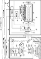
- FIG. 1 schematically shows a configuration of a laser processing system 10 including a laser processing device 14 according to a comparative example.
- FIG. 2A shows an example of a laser light irradiation region 141 on the mask 140.
- FIG. 2B is a plan view showing an example of the mask 140 irradiated with laser light in the comparative example.
- FIG. 3 is a plan view showing an example of a laser processing method of the workpiece 160 by the beam scanning method.
- FIG. 4 is a flowchart showing the operation of the laser processing control unit 100.
- FIG. 5 is a flowchart showing an example of processing contents of reading the laser processing condition parameter.
- FIG. 1 schematically shows a configuration of a laser processing system 10 including a laser processing device 14 according to a comparative example.
- FIG. 2A shows an example of a laser light irradiation region 141 on the mask 140.
- FIG. 2B is a plan view showing an example of the mask 140 irradiated with laser light in
- FIG. 6 is a flowchart showing an example of processing contents of calculation and setting of control parameters of the laser processing apparatus 14.
- FIG. 7 is a flowchart showing an example of processing contents of beam scan processing.
- FIG. 8 schematically shows the configuration of the laser processing system 10 including the laser processing device 14 according to the first embodiment of the present disclosure.
- FIG. 9 is a flowchart showing an example of processing contents of calculation and setting of control parameters of the laser processing apparatus 14 executed in the first embodiment.
- 10A and 10B are plan views showing an example of the mask 140 irradiated with laser light in the first embodiment.
- 11A and 11B show configuration examples of the fly-eye lens 134 and the zoom condenser lens 136a.
- FIG. 12A and 12B show configuration examples of the X-direction fly-eye lens 134x and the X-direction zoom condenser lens 136x.
- FIG. 13 is a flowchart showing an example of processing contents of reading laser processing condition parameters executed in the second embodiment.
- FIG. 14 is a flowchart showing an example of processing contents of calculation and setting of control parameters of the laser processing apparatus 14 executed in the second embodiment.
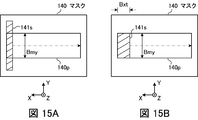
- 15A and 15B are plan views showing an example of the mask 140 irradiated with laser light in the second embodiment.
- FIG. 16 schematically shows a configuration of a laser processing system 10 including a laser processing device 14 according to the third embodiment of the present disclosure.
- FIG. 17 is a flowchart showing an example of processing contents of reading laser processing condition parameters executed in the third embodiment.
- FIG. 18 is a flowchart showing an example of processing contents of calculation and setting of control parameters of the laser processing apparatus 14 executed in the third embodiment.
- FIG. 19 is a flowchart showing an example of the processing contents of the beam scan processing executed in the third embodiment.
- 20A and 20B are plan views showing an example of a mask 140 irradiated with laser light in the third embodiment.
- FIG. 21 is a plan view showing an example of a laser processing method for the workpiece 160 according to the third embodiment.
- FIG. 22 schematically shows the configuration of the laser processing system 10 including the laser processing device 14 according to the fourth embodiment of the present disclosure.
- 23A and 23B show an example of the configuration of the scaling optical system 170d in the fourth embodiment, together with the X-direction fly-eye lens 134x and the X-direction zoom condenser lens 136x.
- Laser processing apparatus and laser processing system according to comparative example 1.1 Configuration 1.1.1 Configuration of laser apparatus 1.1.2 Configuration of laser processing apparatus 1.2 Operation 1.2.1 Operation of laser apparatus 1.2 .2 Operation of laser processing apparatus 1.2.3 Movement of irradiation area on mask 1.2.4 Movement of irradiation area on workpiece 1.2.5 Operation of laser processing control section 1.2.5.1 Main Flow 1.2.5.2 Details of reading parameters for laser processing conditions 1.2.5.3 Details of calculation and setting of control parameters 1.2.5.4 Details of beam scan processing 1.3 Problem 2. Laser processing apparatus capable of independently changing vertical and horizontal irradiation width 2.1 Configuration 2.2 Operation 2.2.1 Calculation and setting of control parameters 2.2.2 Movement of irradiation area on mask 2.3 Action 2.4 2.
- FIG. 1 schematically shows a configuration of a laser processing system 10 including a laser processing device 14 according to a comparative example.
- the laser processing system 10 includes a laser device 12, an optical path tube 13, and a laser processing device 14.
- the laser device 12 is a laser device that outputs an ultraviolet laser beam.
- the laser device 12 may be a discharge excitation laser device using F 2 , ArF, KrF, XeCl, or XeF as a laser medium.
- the laser device 12 includes an oscillator 20, a monitor module 24, a shutter 26, and a laser control unit 28.
- the oscillator 20 includes a chamber 30, a rear mirror 33, an output coupling mirror 34, a charger 36, and a pulse power module (PPM) 38.
- An excimer laser gas is sealed in the chamber 30.
- the chamber 30 includes a pair of electrodes 43 and 44, an insulating member 45, and windows 47 and 48.
- a plurality of conductive members 29 are embedded in the insulating member 45.
- the electrode 43 is supported by the insulating member 45.
- the electrode 43 is electrically connected to the pulse power module 38 via the conductive member 29.
- the electrode 44 is connected to the ground potential via a conductive member forming the chamber 30.
- the rear mirror 33 and the output coupling mirror 34 form an optical resonator.
- the rear mirror 33 is a flat substrate coated with a highly reflective film
- the output coupling mirror 34 is a flat substrate coated with a partially reflective film.
- the chamber 30 is arranged in the optical path of the optical resonator.
- the monitor module 24 includes a beam splitter 50 and an optical sensor 52.
- the shutter 26 is arranged in the optical path of the laser light that has passed through the beam splitter 50.
- the optical path of the laser light may be sealed by the housing 60 and the optical path tube 13 and may be purged with N 2 gas.
- the laser processing device 14 includes an irradiation optical system 70, a frame 72, an XYZ stage 74, and a laser processing control unit 100.
- the irradiation optical system 70 and the XYZ stage 74 are fixed to the frame 72.
- the workpiece 160 is supported on the table 76 of the XYZ stage 74.
- the table 76 is an example of a mounting table on which the workpiece 160 is mounted.
- the workpiece 160 may be, for example, an interposer substrate that relays an LSI (large-scale integrated circuit) chip and a main printed circuit board, or a flexible printed circuit board.
- Examples of the electrically insulating material forming this substrate include polymer materials, glass epoxy materials, and glass materials.
- the irradiation optical system 70 includes a high reflection mirror 111 and a high reflection mirror 112, an attenuator 120, a shaping optical system 130, a uniaxial stage 138, a mask 140, a projection optical system 145, a window 146, and a housing 150. And, including.
- the high-reflection mirror 111 is arranged in the optical path of the laser light that has passed through the optical path tube 13.
- the high-reflecting mirror 111 is arranged so that the laser light passes through the attenuator 120 and enters the high-reflecting mirror 112.
- the attenuator 120 is arranged in the optical path between the high reflection mirror 111 and the high reflection mirror 112.
- the attenuator 120 includes two partial reflection mirrors 121 and 122 and rotating stages 123 and 124.
- the rotary stages 123 and 124 are configured to be able to change the incident angle of the laser light with respect to the partial reflection mirrors 121 and 122, respectively.
- the high-reflection mirror 112 is arranged so that the laser light that has passed through the attenuator 120 enters the shaping optical system 130.
- the shaping optical system 130 includes a high-reflection mirror 133, a fly-eye lens 134, and a condenser lens 136.
- the high-reflection mirror 133 included in the shaping optical system 130 is arranged so that the incident laser light is incident on the fly-eye lens 134.
- the fly-eye lens 134 is arranged so that the focal plane of the fly-eye lens 134 and the front focal plane of the condenser lens 136 coincide with each other.
- the condenser lens 136 is arranged such that the back focal plane of the condenser lens 136 and the position of the mask 140 are aligned with each other.
- the shaping optical system 130 illuminates the mask 140 by Koehler illumination with the above configuration.
- FIG. 2A shows an example of a laser beam irradiation region 141 on the mask 140.
- the irradiation region 141 is a cross section of the optical path of the laser light and corresponds to a cross section along the surface of the mask 140.
- the irradiation area 141 corresponds to the first irradiation area in the present disclosure.
- the irradiation area 141 has a rectangular shape.
- the rectangular shape has a short side and a long side.
- the direction parallel to the short side of the rectangular irradiation region 141 is the X-axis direction, and the direction parallel to the long side is the Y-axis direction.
- the irradiation width in the direction parallel to the short side is Bx, and the irradiation width in the direction parallel to the long side is By.
- the shaping optical system 130 is supported by the plate 135.
- the plate 135 is supported by the uniaxial stage 138 so as to be movable in the X-axis direction indicated by the double-headed arrow A together with the shaping optical system 130.
- the irradiation region 141 moves on the mask 140 in the X-axis direction.
- the mask 140 is, for example, a mask in which a pattern of a metal or dielectric multilayer film is formed on a synthetic quartz substrate that transmits excimer laser light that is ultraviolet light. For example, a pattern of holes having a diameter of 5 ⁇ m to 30 ⁇ m is formed on the mask 140 when a via hole is formed on a printed circuit board as the workpiece 160.
- the projection optical system 145 is arranged so that an inverted image of the mask 140 is formed on the surface of the workpiece 160.
- the projection optical system 145 may be a reduction projection optical system including a combination lens of a plurality of lenses 143 and 144.
- the window 146 is arranged in the optical path of the laser light between the projection optical system 145 and the workpiece 160.
- the window 146 is arranged in a hole provided in the housing 150 via an O-ring (not shown) or the like.
- the window 146 may be a CaF 2 crystal that transmits an excimer laser beam or a synthetic quartz substrate having both surfaces coated with an antireflection film.
- the housing 150 may be sealed with an O-ring or the like so as to prevent the outside air from entering the housing 150, and may be purged with N 2 gas.
- the laser processing control unit 100 controls the operations of the attenuator 120, the 1-axis stage 138, and the XYZ stage 74.
- the laser processing control unit 100 is configured to transmit data of the target pulse energy Et and output a light emission trigger to the laser device 12.
- the laser control unit 28 sets the charging voltage in the charger 36 based on the data of the target pulse energy Et received from the laser processing control unit 100. Send a signal.
- the laser control unit 28 also transmits a light emission trigger to the switch 39 included in the pulse power module 38 based on the light emission trigger received from the laser processing control unit 100.
- the switch 39 of the pulse power module 38 is turned on when receiving a light emission trigger from the laser control unit 28.
- the pulse power module 38 When the switch 39 is turned on, the pulse power module 38 generates a pulsed high voltage from the electric energy charged in the charger 36.
- the pulse power module 38 applies this high voltage between the pair of electrodes 43 and 44.
- the light generated in the chamber 30 goes out of the chamber 30 through the windows 47 and 48.
- the light emitted from the window 48 of the chamber 30 is reflected by the rear mirror 33 with high reflectance and returned to the chamber 30.
- the output coupling mirror 34 transmits a part of the light emitted from the window 47 of the chamber 30 and outputs it, and reflects the other part of the light to return it to the chamber 30.
- the light emitted from the chamber 30 reciprocates between the rear mirror 33 and the output coupling mirror 34, is amplified each time it passes through the discharge space between the pair of electrodes 43 and 44, and causes laser oscillation.
- laser light is output from the output coupling mirror 34. This laser light is pulsed laser light.
- the monitor module 24 detects the pulse energy of the laser light output from the output coupling mirror 34.
- the monitor module 24 transmits the detected pulse energy data to the laser controller 28.
- the laser control unit 28 feedback-controls the charging voltage set in the charger 36 based on the pulse energy measurement data received from the monitor module 24 and the target pulse energy Et data received from the laser processing control unit 100. ..
- the XYZ stage 74 positions the table 76 so that an inverted image of the mask 140 is formed in a desired processing target region of the workpiece 160.
- the laser light transmitted through the beam splitter 50 of the monitor module 24 enters the laser processing device 14 via the optical path tube 13.
- the laser light is guided to the workpiece 160 by the irradiation optical system 70 as follows.
- the laser light that has entered the laser processing device 14 is reflected by the high-reflection mirror 111, passes through the attenuator 120, and then is reflected by the high-reflection mirror 112 in the X-axis direction.
- the laser light reflected by the high-reflection mirror 112 is shaped into a rectangular beam by the shaping optical system 130 so that the light intensity distribution is spatially uniformized.
- the laser light emitted from the shaping optical system 130 enters the mask 140.
- the irradiation region 141 moves on the mask 140 in the X-axis direction at the moving speed Vxm as the shaping optical system 130 moves in the X-axis direction at the moving speed Vxm by driving the uniaxial stage 138.
- the laser beam irradiation region 161 of the workpiece 160 has a shape in which a portion of the mask pattern formed on the mask 140, which corresponds to the irradiation region 141, is reduced.
- the irradiation region 161 is a cross section of the optical path of the laser light and corresponds to a cross section along the surface of the workpiece 160.
- the irradiation area 161 corresponds to the second irradiation area in the present disclosure.
- M is the magnification of the projection optical system 145. Since the projection optical system 145 is a reduction projection optical system, M has a positive value smaller than 1. M may be a value in the range of 1 ⁇ 2 or more and 1 ⁇ 4 or less, for example.
- the moving direction of the irradiation region 141 and the moving direction of the irradiation region 161 due to the driving of the uniaxial stage 138 are opposite to each other.
- the irradiation width in the direction parallel to the short side of the irradiation region 161 is M ⁇ Bx, and the irradiation width in the direction parallel to the long side is M ⁇ By.
- FIG. 2B is a plan view showing an example of the mask 140 irradiated with laser light in the comparative example.
- the mask 140 has a pattern area 140p in which a mask pattern is formed.
- the irradiation region 141 moves to the right from the initial position 141s located at the left end of FIG. 2B.
- the entire pattern area 140p is irradiated with the laser light.
- the irradiation region 141 moves from the right end in FIG. 2B to the left. At this time as well, the entire pattern area 140p is irradiated with the laser light.
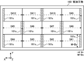
- FIG. 3 is a plan view showing an example of a laser processing method for the work piece 160 by the beam scanning method.
- the processing surface of the workpiece 160 is divided into 12 processing target areas from “S#1” to “S#12”.
- the order of the symbols from "S#1" to "S#12" corresponds to the processing order of the workpiece 160 by the beam scanning method.
- the dashed-dotted arrow indicates the moving direction of the irradiation region 161 in each processing target region.
- the XYZ stage 74 is operated to move the workpiece 160 and stop the XYZ stage 74 so that the first processing target area S#1 matches the area where the inverted image of the mask 140 is formed. Then, the mask 140 is irradiated with laser light, and the laser light irradiation region 141 in the mask 140 is moved rightward from the initial position 141 s located at the left end of FIG. 2B by the uniaxial stage 138. As a result, the laser light irradiation area 161 of the workpiece 160 moves leftward from the initial position 161s located at the right end of the processing target area S#1 in FIG. The processing of the processing target area S#1 is completed by this one-time beam scanning operation.
- the laser light irradiation is stopped.
- the XYZ stage 74 is operated to move the workpiece 160 and stop the XYZ stage 74 so that the next processing target area S#2 matches the area where the inverted image of the mask 140 is formed.
- the mask 140 is irradiated with laser light, and the laser light irradiation region 141 in the mask 140 is moved leftward from the right end in FIG. 2B by the uniaxial stage 138.
- the laser light irradiation area 161 of the workpiece 160 moves to the right from the initial position 161s located at the left end of the processing target area S#2 in FIG. This completes the processing of the processing target area S#2.
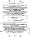
- FIG. 4 is a flowchart showing the operation of the laser processing control section 100. Laser processing by the beam scanning method is performed as follows.
- step S11 the workpiece 160 is set on the table 76 of the XYZ stage 74.
- the workpiece 160 is set on the table 76 by, for example, a work transfer robot (not shown) controlled by the laser processing control unit 100 or another automatic transfer device.
- step S12 the laser processing control unit 100 reads the laser processing condition parameters.
- the laser processing condition parameters will be described later with reference to FIG.
- step S14 the laser processing control unit 100 controls the XYZ stage 74 in the Z-axis direction so that the image of the mask 140 is formed on the surface of the workpiece 160.
- step S15 the laser processing control unit 100 controls the XYZ stage 74 in the X-axis direction and the Y-axis direction so that the image of the mask 140 is formed in the first processing target region S#1 of the workpiece 160. ..
- step S16 the laser processing control unit 100 calculates and sets the control parameters of the laser processing device 14.
- the control parameters of the laser processing device 14 will be described later with reference to FIG.
- step S17 the laser processing control unit 100 sets the value of the parameter Xa representing the beam scanning direction in the workpiece 160 to the initial value -1.
- step S20 the laser processing control unit 100 controls the beam scanning processing.
- the laser processing control unit 100 performs a beam scan operation on one processing target area to process the processing target area.
- the beam scan processing will be described later with reference to FIG. 7.
- step S22 the laser processing control unit 100 determines whether or not the beam scan processing of the entire workpiece 160 has been completed. If NO is determined in step S22, the laser processing control unit 100 proceeds to step S24.
- step S24 the laser processing control unit 100 controls the XYZ stage 74 in either the X-axis direction or the Y-axis direction so that the image of the mask 140 is formed in the next processing target region, and then in step S20. Return. The laser processing controller 100 repeats the processing from step S20 to step S22 until the beam scanning processing of all the processing target areas is completed.
- step S22 the laser processing control unit 100 ends the flowchart of FIG.
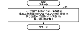
- FIG. 5 is a flowchart showing an example of processing contents of reading laser processing condition parameters.
- the flowchart shown in FIG. 5 corresponds to the subroutine of step S12 in FIG.
- step S31 the laser processing control unit 100 reads the following laser processing condition parameters from a storage device (not shown).
- A Target value Ft of fluence on the surface of the workpiece 160
- B Number of irradiation pulses Np to the same position
- C Repetition frequency f
- the irradiation pulse number Np to the same position is an integer of 2 or more, for example.
- the laser processing control unit 100 returns to the main flow of FIG. 4 after step S31.
- FIG. 6 is a flowchart showing an example of processing contents of calculation and setting of the control parameter of the laser processing apparatus 14.
- the flowchart shown in FIG. 6 corresponds to the subroutine of step S16 of FIG.
- step S51 the laser processing control unit 100 calculates the target value Tt of the transmittance T of the attenuator 120 so that the fluence F on the surface of the workpiece 160 becomes the target value Ft.
- the calculation of the target value Tt is performed as follows.
- Tp be the transmittance of the optical system until the laser beam output from the laser device 12 reaches the workpiece 160 when the transmittance of the attenuator 120 is maximum.
- the magnification of the projection optical system 145 is M.
- the fluence F on the surface of the workpiece 160 is obtained by dividing the pulse energy T ⁇ Tp ⁇ Et on the surface of the workpiece 160 by the area M 2 ⁇ Bx ⁇ By of the laser light irradiation region 161 in the workpiece 160. Then, it is expressed by the following equation (1).
- F M ⁇ 2 (T ⁇ Tp ⁇ Et)/(Bx ⁇ By) (1)
- the target value Tt of the transmittance T of the attenuator 120 which is set to set the fluence F on the surface of the workpiece 160 to the target value Ft, is expressed by the following Expression (2).
- Tt (M 2 /Tp)(Ft/Et)(Bx ⁇ By) (2)
- step S52 the laser processing control unit 100 sets the transmittance T of the attenuator 120 to the target value Tt. That is, the laser processing control unit 100 controls the rotary stages 123 and 124 to adjust the angles of the partial reflection mirrors 121 and 122 so that the transmittance T of the attenuator 120 approaches the target value Tt.
- step S58 the laser processing control unit 100 calculates the absolute value Vxmi of the drive speed of the uniaxial stage 138.
- the absolute value Vxmi of the driving speed of the uniaxial stage 138 is the same as the absolute value
- the time required to irradiate the same position with the pulsed laser light having the repetition frequency f Np times is Np/f.
- the absolute value of the driving speed of the uniaxial stage 138 is expressed by the following formula (3) by dividing the irradiation width Bx in the direction parallel to the short side of the irradiation region 141 by the required time Np/f.
- Vxmi f ⁇ Bx/Np (3)
- step S58 the laser processing control unit 100 exits the flowchart of FIG. 6 and returns to the main flow of FIG.
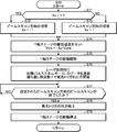
- FIG. 7 is a flowchart showing an example of processing contents of beam scan processing.
- the flowchart shown in FIG. 7 corresponds to the subroutine of step S20 of FIG.
- step S71 the laser processing control unit 100 determines whether or not the value of the parameter Xa is 1. If YES is determined in step S71, that is, if the value of the parameter Xa is 1, the laser processing control unit 100 proceeds to step S72 and sets the value of the parameter Xa to -1.
- step S71 that is, if the value of the parameter Xa is -1, the laser processing control unit 100 proceeds to step S73 and sets the value of the parameter Xa to 1. ..
- the laser processing control unit 100 reverses the positive and negative signs of the parameter Xa and switches the beam scanning direction to the direction opposite to the previously set beam scanning direction.
- the value of the parameter Xa is set to the initial value -1.
- the value of the parameter Xa is set to 1 in step S73.
- the direction in which the irradiation region 161 moves on the surface of the workpiece 160 is, for example, the positive direction of the X axis and is the left direction in FIG.
- the laser processing control unit 100 proceeds to S74.
- step S74 the laser processing control unit 100 sets the drive speed of the uniaxial stage 138.
- the driving speed of the uniaxial stage 138 is equal to both the moving speed Vxm of the shaping optical system 130 during the uniform linear motion and the moving speed Vxm of the irradiation region 141, and is determined according to the following equation (4).
- Vxm -Xa.Vxmi (4)
- various parameters for controlling the uniaxial stage 138 may be set so that acceleration and deceleration before and after the uniform velocity linear motion are performed in a predetermined time.
- the driving direction of the uniaxial stage 138 is the negative direction of the X axis.
- the moving direction of the irradiation region 161 of the laser beam on the workpiece 160 is the positive direction of the X axis.
- the driving direction of the uniaxial stage 138 is the positive direction of the X axis.
- the moving direction of the laser light irradiation region 161 in the workpiece 160 is the negative direction of the X axis.
- step S75 the laser processing control unit 100 starts driving the uniaxial stage 138.
- the shaping optical system 130 is accelerated by the uniaxial stage 138, and then moved linearly at a constant velocity.
- step S76 the laser processing control unit 100 sends the target pulse energy Et data to the laser control unit 28. Further, the laser processing control unit 100 starts output of the light emission trigger at the repetition frequency f to the laser control unit 28. As a result, the output of laser light from the laser device 12 is started.
- the uniaxial stage 138 is controlled so that the irradiation region 141 at the time when the output of the laser light is started coincides with the initial position 141s.
- step S77 the laser processing control unit 100 determines whether or not the beam scanning in the set beam scanning direction is completed. That is, it is determined whether the irradiation area 141 has moved from one end to the other end of the pattern area 140p of the mask 140 in the X-axis direction.
- the laser processing control unit 100 repeats step S77 until YES is determined in step S77. As a result, the laser light is applied to the processing target area of the workpiece 160. If YES is determined in step S77, the laser processing control unit 100 proceeds to step S78. In step S78, the laser processing control unit 100 stops the output of the light emission trigger. As a result, the output of the laser light from the laser device 12 is stopped.
- step S79 the laser processing control unit 100 stops driving the uniaxial stage 138. As a result, the shaping optical system 130 is decelerated and then stopped.
- step S79 the laser processing control unit 100 exits the flowchart of FIG. 7 and returns to the main flow of FIG.
- the transmittance of the attenuator 120 is changed in order to bring the fluence F closer to the target value Ft. Therefore, of the energy of the laser light generated in the laser device 12, the attenuation amount in the attenuator 120 is wasted.
- the target value Ft of the fluence F required for processing is high, the fluence F when the transmittance of the attenuator 120 is maximized needs to be high.
- the irradiation width Bx in the direction parallel to the short side of the irradiation region 141 needs to be set to a small value.
- the irradiation width By in the direction parallel to the long side of the laser beam irradiation region 141 in the mask 140 is substantially equal to the width of the pattern region 140p of the mask 140 in the Y-axis direction. ..
- the pattern areas 140p of the mask 140 are not always the same size.
- the width of the pattern area 140p of the mask 140 in the Y-axis direction is small, the portion of the light with which the mask 140 is irradiated, which is outside the pattern area 140p, is wasted.
- the laser processing apparatus 14 is configured to be able to independently change the irradiation width Bx in the direction parallel to the short side of the irradiation region 141 and the irradiation width By in the direction parallel to the long side. ..
- the laser processing device 14 is configured such that one of the irradiation width Bx in the direction parallel to the short side of the irradiation region 141 and the irradiation width By in the direction parallel to the long side can be fixed and the other can be changed.
- FIG. 8 schematically shows a configuration of a laser processing system 10 including a laser processing apparatus 14 according to the first embodiment of the present disclosure.
- the shaping optical system 130 included in the laser processing device 14 includes a zoom condenser lens 136a instead of the condenser lens 136 described with reference to FIG.
- the laser processing device 14 may not include the attenuator 120 described with reference to FIG.
- the zoom condenser lens 136a is arranged at a position where the laser light passing through the fly-eye lens 134 is incident.
- the zoom condenser lens 136a not only illuminates the mask 140 with a rectangular beam by Koehler illumination in combination with the fly-eye lens 134, but also the irradiation width Bx in the direction parallel to the short side of the irradiation region 141 and the direction parallel to the long side.
- the irradiation width By at is independently changeable.
- the zoom condenser lens 136a is configured so that one of the irradiation width Bx in the direction parallel to the short side of the irradiation region 141 and the irradiation width By in the direction parallel to the long side can be fixed and the other can be changed.
- the irradiation width Bx in the direction parallel to the short side corresponds to the first irradiation width in the present disclosure.
- the irradiation width By in the direction parallel to the long side corresponds to the second irradiation width in the present disclosure.
- a configuration example of the zoom condenser lens 136a will be described later with reference to FIGS. 11A, 11B, 12A, and 12B. In other respects, the configuration of the first embodiment is similar to the configuration of the comparative example.
- FIG. 9 is a flowchart showing an example of processing contents of calculation and setting of the control parameter of the laser processing apparatus 14 executed in the first embodiment.
- the flowchart shown in FIG. 9 corresponds to the subroutine of step S16 of FIG. 4, and is executed instead of the flowchart of FIG. 6 in the above-described comparative example.
- step S55a the laser processing control unit 100 calculates the target value Bxt of the irradiation width Bx in the direction parallel to the short side of the irradiation region 141 so that the fluence on the surface of the mask 140 becomes the target value Fmt.
- the pulse energy on the surface of the mask 140 substantially matches the target pulse energy Et.
- the fluence on the surface of the mask 140 is obtained by dividing the pulse energy Et by the area Bx ⁇ By of the laser light irradiation region 141 in the mask 140. Therefore, the target value Bxt of the irradiation width Bx in the direction parallel to the short side of the irradiation region 141 is represented by the following formula (6).
- Bxt Et/(Fmt ⁇ By) (6)
- step S58 the laser processing control unit 100 calculates the absolute value Vxmi of the drive speed of the uniaxial stage 138.
- the process of step S58 is similar to that described with reference to FIG.
- step S59a the laser processing control unit 100 controls the zoom condenser lens 136a to adjust the irradiation width Bx in the direction parallel to the short side of the irradiation region 141 to the target value Bxt.
- the fluence on the surface of the mask 140 can be brought close to the target value Fmt, and the fluence on the surface of the workpiece 160 can be made close to the target value Ft.
- the irradiation width By in the direction parallel to the long side of the irradiation region 141 may be fixed.
- step S59a the laser processing control unit 100 exits the flowchart of FIG. 9 and returns to the main flow of FIG.
- FIGS. 10A and 10B are plan views showing an example of the mask 140 to which laser light is irradiated in the first embodiment.
- the zoom condenser lens 136a is configured to be able to change the irradiation width Bx in the direction parallel to the short side of the irradiation region 141.
- the shape and size of the initial position 141s shown in each of FIGS. 10A and 10B correspond to the shape and size of the irradiation region 141 of the laser light in the mask 140.
- the fluence on the surface of the mask 140 does not reach the target value Fmt in a state where the irradiation region 141 has the shape and size shown as the initial position 141s in FIG. 10A, the irradiation region 141 is in the direction parallel to the short side.
- the irradiation width Bx is narrowed.
- FIG. 10B by setting the target value Bxt of the irradiation width Bx in the direction parallel to the short side to a small value, the fluence on the surface of the mask 140 can be brought close to the target value Fmt.
- the target value Bxt of the irradiation width Bx in the direction parallel to the short side may be set to a large value.
- the operation of the first embodiment is similar to the operation of the comparative example.
- the irradiation width Bx in the direction parallel to the short side of the irradiation region 141 is changed according to the target value Fmt of the fluence, so that the fluence can be changed without using the attenuator 120. Can be adjusted. Thereby, it is possible to suppress the waste of energy of the laser light.
- the fluence target value Fmt when the fluence target value Fmt is low, the irradiation width Bx in the direction parallel to the short side can be increased. As a result, the absolute value Vxmi of the drive speed of the uniaxial stage 138 calculated in step S58 increases. Therefore, the processing speed can be improved and the throughput can be improved.
- FIGS. 11A and 11B show configuration examples of the fly-eye lens 134 and the zoom condenser lens 136a.
- FIG. 11A is a view of these lenses viewed along the Y-axis direction
- FIG. 11B is a view of these lenses viewed along the X-axis direction.
- the fly-eye lens 134 includes an X-direction fly-eye lens 134x and a Y-direction fly-eye lens 134y.
- the X-direction fly-eye lens 134x is a lens in which a plurality of cylindrical surfaces are arranged in the X-axis direction, and each of the cylindrical surfaces has a focal axis in the Y-axis direction.
- the Y-direction fly-eye lens 134y is a lens in which a plurality of cylindrical surfaces are arranged in the Y-axis direction, and each of the cylindrical surfaces has a focal axis in the X-axis direction.
- the zoom condenser lens 136a includes an X-direction zoom condenser lens 136x and a Y-direction zoom condenser lens 136y.
- the X-direction zoom condenser lens 136x includes, for example, three cylindrical lenses, and each of these cylindrical lenses has a focal axis in the Y-axis direction.
- the Y-direction zoom condenser lens 136y includes, for example, three cylindrical lenses, and each of these cylindrical lenses has a focal axis in the X-axis direction. The configuration of the three cylindrical lenses will be described later with reference to FIGS. 12A and 12B.
- the X-direction fly-eye lens 134x is arranged so that the focal plane of the X-direction fly-eye lens 134x and the front focal plane of the X-direction zoom condenser lens 136x coincide with each other.
- the X-direction zoom condenser lens 136x is arranged such that the rear focal plane of the X-direction zoom condenser lens 136x and the position of the mask 140 match.
- the Y-direction fly-eye lens 134y is arranged so that the focal plane of the Y-direction fly-eye lens 134y and the front focal plane of the Y-direction zoom condenser lens 136y coincide with each other.
- the Y-direction zoom condenser lens 136y is arranged so that the rear focal plane of the Y-direction zoom condenser lens 136y and the position of the mask 140 match.
- the laser light incident on each of the plurality of cylindrical surfaces included in the X-direction fly-eye lens 134x is magnified by the cylindrical surface and is irradiated on the mask 140 by the X-direction zoom condenser lens 136x.
- the lights incident on the plurality of cylindrical surfaces are superposed at the same position on the mask 140, and the light intensity distribution in the X-axis direction is made uniform.
- the Y-direction fly-eye lens 134y and the Y-direction zoom condenser lens 136y make the light intensity distribution in the Y-axis direction uniform.
- the light intensity distributions are made uniform in the X-axis direction and the Y-axis direction, and the rectangular irradiation area 141 is formed.
- the irradiation width Bx in the direction parallel to the short side of the irradiation region 141 and the irradiation width By in the direction parallel to the long side can be changed by the X-direction zoom condenser lens 136x and the Y-direction zoom condenser lens 136y, respectively.
- the three cylindrical lenses constituting the X-direction zoom condenser lens 136x include two cylindrical convex lenses and one cylindrical concave lens arranged between the two cylindrical convex lenses.
- the focal length of the X-direction zoom condenser lens 136x is changed by adjusting the distance between the X-direction fly-eye lens 134x and each of the three cylindrical lenses.
- the focal length of the X-direction zoom condenser lens 136x By changing the focal length of the X-direction zoom condenser lens 136x, the irradiation width Bx in the direction parallel to the short side of the irradiation area 141 can be changed.
- the irradiation width Bx in the direction parallel to the short side of the irradiation region 141 is proportional to the focal length of the X-direction zoom condenser lens 136x.
- FIG. 12A shows the case where the irradiation width Bx in the direction parallel to the short side is reduced, and FIG.
- FIGS. 12A and 12B show the case where the irradiation width Bx in the direction parallel to the short side is increased.
- the first light ray condensed at the center of the irradiation area 141 and the first light ray condensed at the right end of the irradiation area 141 Two rays are shown and the other rays are not shown.
- the distance between the first light ray and the second light ray is half the irradiation width Bx.
- the X-direction zoom condenser lens 136x shown in FIGS. 12A and 12B which has a three-lens structure, not only can change the irradiation width Bx, but also satisfies the following conditions.
- the distance from the pupil plane (X-direction fly-eye lens 134x) to the image plane (mask 140) is constant.
- the telecentricity in the pupil plane and the image plane does not substantially change.
- the cylindrical convex lens located near the X-direction fly-eye lens 134x functions as a focusing lens.
- the cylindrical concave lens functions as a pre-stage variator, and the cylindrical convex lens arranged near the mask 140 functions as a main variator.
- the main variator also has the role of improving the telecentricity of the chief ray.
- the configurations of the Y-direction fly-eye lens 134y and the Y-direction zoom condenser lens 136y are the same as those described with reference to FIGS. 12A and 12B. Thereby, the irradiation width Bx in the direction parallel to the short side of the irradiation region 141 and the irradiation width By in the direction parallel to the long side can be changed independently.
- one of the irradiation width Bx in the direction parallel to the short side and the irradiation width By in the direction parallel to the long side may be fixed and only the other may be changed.
- the irradiation width By in the direction parallel to the long side may be fixed, and only the irradiation width Bx in the direction parallel to the short side may be changed to adjust the fluence. ..
- a condenser lens including a cylindrical lens may be used instead of the Y-direction zoom condenser lens 136y.
- the irradiation width Bx in the direction parallel to the short side may be fixed, and only the irradiation width By in the direction parallel to the long side may be changed to adjust the fluence.
- a condenser lens including a cylindrical lens may be used instead of the X-direction zoom condenser lens 136x.
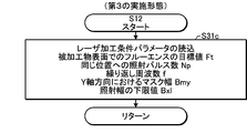
- FIG. 13 is a flowchart showing an example of processing contents of reading a laser machining condition parameter executed in the second embodiment.
- the flowchart shown in FIG. 13 corresponds to the subroutine of step S12 of FIG. 4, and is executed instead of the flowchart of FIG. 5 in the above-described comparative example.
- step S31b the laser processing control unit 100 reads the following laser processing condition parameters from a storage device (not shown).
- A Target value Ft of fluence on the surface of the workpiece 160
- B Number of irradiation pulses Np to the same position
- C Repetition frequency f
- D Mask width Bmy in the Y-axis direction
- the above (a) to (c) are the same as in the comparative example.
- the Y-axis direction of (d) corresponds to the direction parallel to the long side of the irradiation region 141.
- the mask width Bmy may be the width of the pattern region 140p in which the mask pattern is formed.
- the laser processing control unit 100 returns to the main flow of FIG. 4 after step S31b.
- FIG. 14 is a flowchart showing an example of processing contents of calculation and setting of the control parameter of the laser processing apparatus 14 executed in the second embodiment.
- the flowchart shown in FIG. 14 corresponds to the subroutine of step S16 of FIG. 4, and is executed instead of the flowchart of FIG. 6 in the above-described comparative example.
- step S53a the laser processing control unit 100 calculates the fluence target value Fmt on the surface of the mask 140.
- the process of step S53a is the same as that described with reference to FIG.
- step S55b the laser processing control unit 100 calculates the target value Bxt of the irradiation width Bx in the direction parallel to the short side of the irradiation region 141 so that the fluence on the surface of the mask 140 becomes the target value Fmt.
- the irradiation width in the direction parallel to the long side of the irradiation region 141 is set to the mask width Bmy in the Y-axis direction.
- step S58 the laser processing control unit 100 calculates the absolute value Vxmi of the drive speed of the uniaxial stage 138.
- the process of step S58 is similar to that described with reference to FIG.
- step S59b the laser processing control unit 100 controls the zoom condenser lens 136a to adjust the irradiation width Bx in the direction parallel to the short side of the irradiation region 141 to the target value Bxt, and the irradiation in the direction parallel to the long side.
- the width By is adjusted to the mask width Bmy in the Y-axis direction.
- step S59b the laser processing control unit 100 exits the flowchart of FIG. 14 and returns to the main flow of FIG.
- FIGS. 15A and 15B are plan views showing an example of the mask 140 irradiated with laser light in the second embodiment.
- the zoom condenser lens 136a is configured to be able to change both the irradiation width Bx in the direction parallel to the short side of the laser beam irradiation region 141 in the mask 140 and the irradiation width By in the direction parallel to the long side.
- the shape and size of the initial position 141s shown in each of FIGS. 15A and 15B correspond to the shape and size of the irradiation region 141.
- the irradiation width Bmy in the Y-axis direction is set to the mask width Bmy in the Y-axis direction.
- the target value Bxt of the irradiation width Bx in the direction parallel to the short side is set according to the target value Fmt of fluence.
- the operation of the second embodiment is similar to the operation of the first embodiment.
- the irradiation width By in the direction parallel to the long side is set to the mask width Bmy in the Y-axis direction, so that the pattern area 140p of the mask 140 can be efficiently irradiated. Therefore, it is possible to suppress the waste of energy of the laser light.
- the irradiation width Bx in the direction parallel to the short side can be increased.
- the absolute value Vxmi of the drive speed of the uniaxial stage 138 calculated in step S58 increases. Therefore, the processing speed can be improved and the throughput can be improved.
- the present disclosure is not limited thereto.
- the irradiation width By in the direction parallel to the long side can be changed so as to approach the mask width Bmy in the Y-axis direction, while the irradiation width Bx in the direction parallel to the short side may be fixed.
- FIG. 16 schematically shows the configuration of the laser processing system 10 including the laser processing device 14 according to the third embodiment of the present disclosure.
- the laser processing apparatus 14 includes a biaxial stage 138c instead of the uniaxial stage 138 shown in FIG.
- the 1-axis stage 138 and the 2-axis stage 138c correspond to the moving device in the present disclosure.
- the biaxial stage 138c is configured not only to move the shaping optical system 130 and the irradiation region 141 in the X axis direction but also to move in the Y axis direction.
- the configuration of the third embodiment is similar to that of the first and second embodiments.
- the irradiation width By in the direction parallel to the long side of the irradiation region 141 is set to 1/n times the mask width Bmy in the Y-axis direction of the mask 140. n is a natural number. Then, every time the laser beam is scanned once in the X-axis direction, the irradiation region 141 is moved in the Y-axis direction by Bmy/n, and scanning is performed n times to irradiate the entire pattern region 140p. 4.2.1 Reading Laser Processing Condition Parameters
- FIG. 17 is a flowchart showing an example of processing contents of reading laser processing condition parameters executed in the third embodiment. The flowchart shown in FIG. 17 corresponds to the subroutine of step S12 of FIG. 4, and is executed instead of the flowchart of FIG. 5 in the above-described comparative example.
- step S31c the laser processing control unit 100 reads the following laser processing condition parameters from a storage device (not shown).
- A Target value Ft of fluence on the surface of the workpiece 160
- B Number of irradiation pulses Np to the same position
- C Repetition frequency f
- D Mask width Bmy in the Y-axis direction
- E Lower limit value of irradiation width Bxl
- the lower limit value Bxl of the above (e) is a value determined by the following constraints.
- the value called the Lagrangian invariant can be increased by propagation but not decreased. Letting the image height be h and the maximum ray angle be ⁇ , the Lagrangian invariant is given by h ⁇ tan ⁇ .
- the irradiation width Bx in the direction parallel to the short side of the irradiation region 141 may be reduced as described above. However, if the irradiation width Bx in the direction parallel to the short side of the irradiation region 141 is reduced, the maximum ray angle of the light that the shaping optical system 130 makes incident on the mask 140 increases. This is because the Lagrange invariant does not become small.
- the maximum light ray angle When the maximum light ray angle becomes large, the maximum light ray angle may exceed the numerical aperture of the projection optical system 145 and the light may stick out of the effective diameter of the projection optical system 145. If the light exceeds the effective diameter of the projection optical system 145, the fluence on the surface of the workpiece 160 is reduced. That is, even if the irradiation width Bx in the direction parallel to the short side of the irradiation region 141 is further reduced, the fluence on the surface of the workpiece 160 cannot be increased. Therefore, the irradiation width Bx has a lower limit value Bxl.
- the laser processing control unit 100 may obtain the lower limit value Bxl of the irradiation width Bx by calculation using the equation (8).
- the laser processing control unit 100 returns to the main flow of FIG. 4 after step S31c.
- FIG. 18 is a flowchart showing an example of processing contents of calculation and setting of the control parameter of the laser processing apparatus 14 executed in the third embodiment.
- the flowchart shown in FIG. 18 corresponds to the subroutine of step S16 of FIG. 4, and is executed instead of the flowchart of FIG. 6 in the above-described comparative example.
- step S53a the laser processing control unit 100 calculates the fluence target value Fmt on the surface of the mask 140.
- the process of step S53a is the same as that described with reference to FIG.
- step S54c the laser processing control unit 100 sets the number of scans n to the initial value 1.
- the number of scans n is the number of scans of the irradiation region 141 in the mask 140 in the X-axis direction, and is determined by the processes of steps S55c to S57c.
- step S55c the laser processing control unit 100 calculates the target value Bxt of the irradiation width Bx in the direction parallel to the short side of the irradiation region 141 so that the fluence on the surface of the mask 140 becomes the target value Fmt.
- the mask 140 is scanned n times to irradiate the entire mask width Bmy in the Y-axis direction.
- step S56c the laser processing control unit 100 determines whether the target value Bxt of the irradiation width Bx in the direction parallel to the short side of the irradiation region 141 is the lower limit value Bxl or more.
- step S56c determines whether the target value Bxt of the irradiation width Bx is too small and the light protrudes from the effective diameter of the projection optical system 145. If NO is determined in step S56c, that is, if the target value Bxt of the irradiation width Bx is too small and the light protrudes from the effective diameter of the projection optical system 145, the laser processing control unit 100 proceeds to step S57c. .. In step S57c, the laser processing control unit 100 adds 1 to the value of n to update the value of n, and then returns to step S55c. In this way, 1 is added to the number of scans n until the target value Bxt of the irradiation width Bx is calculated so that the light does not protrude from the effective diameter of the projection optical system 145.
- step S58c the laser processing control unit 100 calculates the absolute value Vxmi of the driving speed of the biaxial stage 138c in the X axis direction.
- the process of step S58c is similar to the process of step S58 described with reference to FIG.
- step S59c the laser processing control unit 100 controls the zoom condenser lens 136a to adjust the irradiation width Bx in the direction parallel to the short side of the irradiation region 141 to the target value Bxt, and the irradiation in the direction parallel to the long side. Adjust the width By to Bmy/n.
- Bmy/n is a value obtained by dividing the mask width Bmy in the Y-axis direction by the number of scans n, and is a value equal to or smaller than the mask width Bmy.
- the high fluence when high fluence cannot be obtained only by reducing the irradiation width Bx in the direction parallel to the short side, the high fluence can be reduced by decreasing the irradiation width By in the direction parallel to the long side. To be able to get.
- step S59c the laser processing control unit 100 exits the flowchart of FIG. 18 and returns to the main flow of FIG.
- FIG. 19 is a flowchart showing an example of the processing content of the beam scan processing executed in the third embodiment.
- the flowchart shown in FIG. 19 corresponds to the subroutine of step S20 of FIG. 4, and is executed instead of the flowchart of FIG. 7 in the above-described comparative example.
- steps S71 to S73 the laser processing control unit 100 reverses the positive and negative signs of the parameter Xa and switches the beam scanning direction to the direction opposite to the previously set beam scanning direction.
- the processing of steps S71 to S73 is the same as that described with reference to FIG. After step S72 or S73, the laser processing control unit 100 proceeds to S74c.
- step S74c the laser processing control unit 100 sets the driving speed of the biaxial stage 138c in the X axis direction.
- step S75c the laser processing control unit 100 starts driving the biaxial stage 138c in the X axis direction.
- steps S74c and S75c are the same as the processes of steps S74 and S75 described with reference to FIG. 7, respectively.
- step S76 the laser processing control unit 100 transmits the data of the target pulse energy Et to the laser control unit 28. Further, the laser processing control unit 100 starts output of the light emission trigger at the repetition frequency f to the laser control unit 28.
- step S77 the laser processing control unit 100 determines whether or not the beam scanning in the set beam scanning direction is completed. If YES is determined in step S77, the laser processing control unit 100 stops the output of the light emission trigger in step S78.
- the processing of steps S76 to S78 is the same as that described with reference to FIG.
- step S79c the laser processing control unit 100 stops driving the biaxial stage 138c in the X axis direction.
- the process of step S79c is the same as the process of step S79 described with reference to FIG.
- step S80c the laser processing control unit 100 determines whether or not the irradiation of the entire mask 140 has been completed.
- step S80c If the beam scanning of n times has not been completed, NO is determined in step S80c. If NO is determined in step S80c, the laser processing control unit 100 proceeds to step S81c. In step S81c, the laser processing control unit 100 drives the biaxial stage 138c in the Y axis direction by Bmy/n. Bmy/n corresponds to the irradiation width in the direction parallel to the long side set in step S59c of FIG. After step S81c, the laser processing control unit 100 returns to step S71, switches the beam scanning direction, and repeats the processing from step S71 to step S80c until the beam scanning of n times is completed.
- step S80c If the beam scanning of n times has been completed, YES is determined in step S80c. If YES is determined in step S80c, the laser processing control unit 100 exits the flowchart of FIG. 19 and returns to the main flow of FIG.
- FIGS. 20A and 20B are plan views showing an example of the mask 140 irradiated with laser light in the third embodiment.
- the zoom condenser lens 136a is configured to be able to change both the irradiation width Bx in the direction parallel to the short side of the laser beam irradiation region 141 in the mask 140 and the irradiation width By in the direction parallel to the long side.
- the shape and size of the initial position 141s shown in each of FIG. 20A and FIG. 20B correspond to the shape and size of the irradiation region 141.
- the irradiation width Bx in the direction parallel to the short side matches the mask width Bmy in the Y-axis direction as shown as the initial position 141s in FIG. 20A, the irradiation width Bx in the direction parallel to the short side. High fluence may not be obtained simply by adjusting. Therefore, as shown in FIG. 20B, a high fluence can be obtained by setting the irradiation width By in the direction parallel to the long side to Bmy/n. Further, the target value Bxt of the irradiation width Bx in the direction parallel to the short side is set according to the target value Fmt of fluence.
- the irradiation region 141 is moved from the initial position 141s in FIG. 20B in the X axis direction to perform the first beam scan, and then is moved in the Y axis direction by Bmy/n. Further, the irradiation region 141 is moved from the initial position 142s in FIG. 20B in the direction opposite to the first beam scan to perform the second beam scan.
- the entire mask 140 is irradiated by performing beam scanning n times.
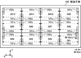
- FIG. 21 is a plan view showing an example of a laser processing method for the work piece 160 in the third embodiment.
- the processing target area from "S#1" to "S#12" shown in FIG. 21 is the same as that described with reference to FIG.
- the XYZ stage 74 is operated to move the workpiece 160 and stop the XYZ stage 74 so that the first processing target area S#1 matches the area where the inverted image of the mask 140 is formed. Then, the mask 140 is irradiated with laser light, and the laser light irradiation region 141 in the mask 140 is moved to the right from the initial position 141s in FIG. 20B by the biaxial stage 138c. As a result, the laser light irradiation area 161 of the workpiece 160 moves leftward from the initial position 161s of the processing target area S#1 in FIG. When the first beam scanning operation is completed, the laser light irradiation is stopped.
- the irradiation region 141 of the laser light on the mask 140 is moved Bmy/n upward in FIG. 20B by the biaxial stage 138c.
- the laser light irradiation area 161 of the workpiece 160 moves downward in FIG.
- the mask 140 is irradiated with laser light, and the laser light irradiation region 141 in the mask 140 is moved leftward from the initial position 142 s in FIG. 20B by the biaxial stage 138 c.
- the laser light irradiation area 161 of the workpiece 160 moves to the right from the initial position 162s of the processing target area S#1 in FIG.
- the laser light irradiation is stopped.
- the processing of the processing target area S#1 is completed by performing the beam scanning operation n times.
- the XYZ stage 74 is operated to move the workpiece 160 and stop the XYZ stage 74 so that the next processing target area S#2 matches the area where the inverted image of the mask 140 is formed.
- the beam scanning operation is performed n times.
- the movement path of the laser light irradiation area 141 in the mask 140 is opposite to the movement path when the first processing target area S#1 is processed. Therefore, the irradiation area 161 of the laser beam on the workpiece 160 moves leftward from the initial position 161s of the processing target area S#2 in FIG. 21, moves upward, and then moves rightward from the initial position 162s. To do.
- the irradiation in the direction parallel to the long side is performed.
- the width By is reduced. This enables laser processing with high fluence without changing the settings of the laser device 12.
- the irradiation width Bx in the direction parallel to the short side of the irradiation region 141 and the irradiation width By in the direction parallel to the long side are changed, but the present disclosure is not limited thereto.
- the irradiation width By in the direction parallel to the long side can be changed to Bmy/n according to the mask width Bmy in the Y-axis direction and the fluence target value Fmt, while the irradiation width Bx in the direction parallel to the short side is fixed. You may keep it.
- FIG. 22 schematically shows a configuration of a laser processing system 10 including a laser processing apparatus 14 according to a fourth embodiment of the present disclosure. ..
- the laser processing device 14 includes a scaling optical system 170d.
- the enlargement/reduction optical system 170d is arranged in the optical path of the laser beam between the high reflection mirror 112 and the shaping optical system 130.
- FIGS. 23A and 23B show an example of the configuration of the enlargement/reduction optical system 170d in the fourth embodiment, together with the X-direction fly-eye lens 134x and the X-direction zoom condenser lens 136x.
- the X-direction fly-eye lens 134x and the X-direction zoom condenser lens 136x are the same as those described with reference to FIGS. 12A and 12B.
- the enlargement/reduction optical system 170d shown in FIGS. 23A and 23B includes, for example, three cylindrical lenses.
- the three cylindrical lenses include two cylindrical convex lenses and one cylindrical concave lens arranged between the two cylindrical convex lenses.
- the focal length of the scaling optical system 170d changes.
- the irradiation width Bxf in the direction parallel to the short side of the irradiation region 131 of the laser light in the X-direction fly-eye lens 134x can be changed.
- the laser light irradiation area 131 in the X-direction fly-eye lens 134x corresponds to the third irradiation area in the present disclosure.
- the irradiation width Bxf in the direction parallel to the short side of the irradiation region 131 is proportional to the focal length of the enlargement/reduction optical system 170d.
- a first light beam that is focused on the center of the irradiation region 131 and a second light beam that is focused on the right end of the irradiation region 131 are shown.
- the illustration of other light rays is omitted.
- the distance between the first light ray and the second light ray is half the irradiation width Bxf in the direction parallel to the short side of the irradiation region 131.
- the configuration of the enlargement/reduction optical system 170d is the same as the configuration of the X-direction zoom condenser lens 136x.
- the lens diameter of the cylindrical lens that constitutes the scaling optical system 170d may be smaller than the lens diameter of the cylindrical lens that constitutes the X-direction zoom condenser lens 136x.
- 23A and 23B show an optical system that changes the irradiation width Bxf in the direction parallel to the short side as the scaling optical system 170d, but the present disclosure is not limited to this.
- the enlargement/reduction optical system 170d instead of the first optical system that changes the irradiation width Bxf in the direction parallel to the short side of the irradiation region 131 of the laser light in the X-direction fly-eye lens 134x, a Y-direction fly-eye lens 134y is used.
- a second optical system that changes the irradiation width in the direction parallel to the long side of the laser light irradiation region may be arranged.
- both the first optical system and the second optical system may be arranged.
- the enlargement/reduction optical system 170d is not limited to an optical system including a cylindrical lens, and may be an optical system including a prism.
- the configuration of the fourth embodiment is the same as the configuration of the first and second embodiments.
- the laser processing apparatus 14 may include a biaxial stage 138c instead of the uniaxial stage 138.
- the maximum ray angle ⁇ of the light that the X-direction zoom condenser lens 136x makes incident on the mask 140 becomes. growing.
- FIG. 12A and FIG. 12B an angle corresponding to twice the maximum light ray angle ⁇ is shown.
- the illumination conditions for the mask 140 change, and the processing performance may change unintentionally.
- the irradiation width of the irradiation region 141 is changed only in one of the direction parallel to the short side or the direction parallel to the long side, or when the irradiation width of the irradiation region 141 is parallel to the short side and the direction parallel to the long side.
- the processing performance differs between the direction parallel to the short side and the direction parallel to the long side. For example, when a circular pattern is processed, it may be processed into an elliptical shape.
- the enlarging/reducing optical system 170d changes the irradiation width in the irradiation region 131 so that an unintended change in processing performance is suppressed even if the magnification of the zoom condenser lens 136a is changed.
- the scaling optical system 170d is set so that the focal length Fo of the scaling optical system 170d is proportional to the focal length Fz of the zoom condenser lens 136a.
- the focal length Fo of the scaling optical system 170d is calculated by the following equation (11).
- Fo Mo ⁇ Fomin (11)
- Fomin is the focal length of the enlargement/reduction optical system 170d when the irradiation width of the laser light irradiation region 131 in the fly-eye lens 134 is minimized.
- the positions of the three cylindrical lenses that form the enlargement/reduction optical system 170d are determined.
- the focal length Fo of the scaling optical system 170d is set in the X-axis direction and the Y-axis direction. And are done separately.
- the enlargement/reduction optical system 170d is adjusted in association with the adjustment of the zoom condenser lens 136a. Thereby, even if the magnification of the zoom condenser lens 136a is changed, an unintended change in the processing performance is suppressed.
Landscapes
- Physics & Mathematics (AREA)
- Optics & Photonics (AREA)
- Engineering & Computer Science (AREA)
- Plasma & Fusion (AREA)
- Mechanical Engineering (AREA)
- Electromagnetism (AREA)
- General Physics & Mathematics (AREA)
- Laser Beam Processing (AREA)
- Lasers (AREA)
Abstract
レーザ加工装置は、被加工物を載置する載置台と、レーザ光の一部を遮断するように構成されたマスクにおけるレーザ光の第1の照射領域が短辺及び長辺を有する矩形状となるように、レーザ光を整形し、短辺に平行な方向における第1の照射領域の第1の照射幅と、長辺に平行な方向における第1の照射領域の第2の照射幅と、の一方を固定し他方を変更可能に構成された整形光学系と、マスクのパターンを載置台に載置された被加工物に投影するように構成された投影光学系と、第1の照射領域を少なくとも短辺に平行な方向に移動させて、載置台に載置された被加工物におけるレーザ光の第2の照射領域を移動させる移動装置と、を備える。
Description
本開示は、レーザ加工装置及び被加工物の加工方法に関する。
近年、半導体露光装置(以下、「露光装置」という)においては、半導体集積回路の微細化および高集積化につれて、解像力の向上が要請されている。このため、露光用光源から放出される光の短波長化が進められている。一般的に、露光用光源には、従来の水銀ランプに代わってガスレーザ装置が用いられる。たとえば、露光用のガスレーザ装置としては、波長248nmの紫外線のレーザ光を出力するKrFエキシマレーザ装置、ならびに波長193nmの紫外線のレーザ光を出力するArFエキシマレーザ装置が用いられる。
また、エキシマレーザ光はパルス幅が約数10nsであって、波長はそれぞれ、248.4nmと193.4nmと短いことから、高分子材料やガラス材料等の直接加工に用いられることがある。
高分子材料における化学結合は、結合エネルギーよりも高いフォトンエネルギーをもつエキシマレーザ光によって切断することができる。そのため、エキシマレーザ光によって高分子材料の非加熱加工が可能となり、加工形状が綺麗になることが知られている。
また、ガラスやセラミックス等はエキシマレーザ光に対する吸収率が高いので、可視及び赤外線レーザ光では加工することが難しい材料であっても、エキシマレーザ光により加工できることが知られている。
高分子材料における化学結合は、結合エネルギーよりも高いフォトンエネルギーをもつエキシマレーザ光によって切断することができる。そのため、エキシマレーザ光によって高分子材料の非加熱加工が可能となり、加工形状が綺麗になることが知られている。
また、ガラスやセラミックス等はエキシマレーザ光に対する吸収率が高いので、可視及び赤外線レーザ光では加工することが難しい材料であっても、エキシマレーザ光により加工できることが知られている。
本開示の1つの観点に係るレーザ加工装置は、被加工物を載置する載置台と、レーザ光の一部を遮断するように構成されたマスクにおけるレーザ光の第1の照射領域が短辺及び長辺を有する矩形状となるように、レーザ光を整形し、短辺に平行な方向における第1の照射領域の第1の照射幅と、長辺に平行な方向における第1の照射領域の第2の照射幅と、の一方を固定し他方を変更可能に構成された整形光学系と、マスクのパターンを載置台に載置された被加工物に投影するように構成された投影光学系と、第1の照射領域を少なくとも短辺に平行な方向に移動させて、載置台に載置された被加工物におけるレーザ光の第2の照射領域を移動させる移動装置と、を備える。
本開示の他の1つの観点に係るレーザ加工装置は、被加工物を載置する載置台と、レーザ光の一部を遮断するように構成されたマスクにおけるレーザ光の第1の照射領域が短辺及び長辺を有する矩形状となるように、レーザ光を整形し、短辺に平行な方向における第1の照射領域の第1の照射幅と、長辺に平行な方向における第1の照射領域の第2の照射幅と、を独立に変更可能に構成された整形光学系と、マスクのパターンを載置台に載置された被加工物に投影するように構成された投影光学系と、第1の照射領域を少なくとも短辺に平行な方向に移動させて、載置台に載置された被加工物におけるレーザ光の第2の照射領域を移動させる移動装置と、を備える。
本開示の1つの観点に係る被加工物の加工方法は、被加工物を載置する載置台と、レーザ光の一部を遮断するように構成されたマスクにおけるレーザ光の第1の照射領域が短辺及び長辺を有する矩形状となるように、レーザ光を整形し、短辺に平行な方向における第1の照射領域の第1の照射幅と、長辺に平行な方向における第1の照射領域の第2の照射幅と、の一方を固定し他方を変更可能に構成された整形光学系と、マスクのパターンを載置台に載置された被加工物に投影するように構成された投影光学系と、第1の照射領域を少なくとも短辺に平行な方向に移動させて、載置台に載置された被加工物におけるレーザ光の第2の照射領域を移動させる移動装置と、を備えたレーザ加工装置を用いて、第1の照射領域が矩形状となるようにレーザ光を整形し、マスクのパターンを載置台に載置された被加工物に投影し、第1の照射領域を少なくとも短辺に平行な方向に移動させることを含む。
本開示の他の1つの観点に係る被加工物の加工方法は、被加工物を載置する載置台と、レーザ光の一部を遮断するように構成されたマスクにおけるレーザ光の第1の照射領域が短辺及び長辺を有する矩形状となるように、レーザ光を整形し、短辺に平行な方向における第1の照射領域の第1の照射幅と、長辺に平行な方向における第1の照射領域の第2の照射幅と、を独立に変更可能に構成された整形光学系と、マスクのパターンを載置台に載置された被加工物に投影するように構成された投影光学系と、第1の照射領域を少なくとも短辺に平行な方向に移動させて、載置台に載置された被加工物におけるレーザ光の第2の照射領域を移動させる移動装置と、を備えたレーザ加工装置を用いて、第1の照射領域が矩形状となるようにレーザ光を整形し、マスクのパターンを載置台に載置された被加工物に投影し、第1の照射領域を少なくとも短辺に平行な方向に移動させることを含む。
本開示のいくつかの実施形態を、単なる例として、添付の図面を参照して以下に説明する。
図1は、比較例に係るレーザ加工装置14を含むレーザ加工システム10の構成を概略的に示す。
図2Aは、マスク140におけるレーザ光の照射領域141の例を示す。図2Bは、比較例においてレーザ光が照射されるマスク140の例を示す平面図である。
図3は、ビームスキャン方式による被加工物160のレーザ加工方法の例を示す平面図である。
図4は、レーザ加工制御部100の動作を示すフローチャートである。
図5は、レーザ加工条件パラメータの読込の処理内容の例を示すフローチャートである。
図6は、レーザ加工装置14の制御パラメータの計算及び設定の処理内容の例を示すフローチャートである。
図7は、ビームスキャン加工の処理内容の例を示すフローチャートである。
図8は、本開示の第1の実施形態に係るレーザ加工装置14を含むレーザ加工システム10の構成を概略的に示す。
図9は、第1の実施形態において実行されるレーザ加工装置14の制御パラメータの計算及び設定の処理内容の例を示すフローチャートである。
図10A及び図10Bは、第1の実施形態においてレーザ光が照射されるマスク140の例を示す平面図である。
図11A及び図11Bは、フライアイレンズ134及びズームコンデンサレンズ136aの構成例を示す。
図12A及び図12Bは、X方向フライアイレンズ134x及びX方向ズームコンデンサレンズ136xの構成例を示す。
図13は、第2の実施形態において実行されるレーザ加工条件パラメータの読込の処理内容の例を示すフローチャートである。
図14は、第2の実施形態において実行されるレーザ加工装置14の制御パラメータの計算及び設定の処理内容の例を示すフローチャートである。
図15A及び図15Bは、第2の実施形態においてレーザ光が照射されるマスク140の例を示す平面図である。
図16は、本開示の第3の実施形態に係るレーザ加工装置14を含むレーザ加工システム10の構成を概略的に示す。
図17は、第3の実施形態において実行されるレーザ加工条件パラメータの読込の処理内容の例を示すフローチャートである。
図18は、第3の実施形態において実行されるレーザ加工装置14の制御パラメータの計算及び設定の処理内容の例を示すフローチャートである。
図19は、第3の実施形態において実行されるビームスキャン加工の処理内容の例を示すフローチャートである。
図20A及び図20Bは、第3の実施形態においてレーザ光が照射されるマスク140の例を示す平面図である。
図21は、第3の実施形態における被加工物160のレーザ加工方法の例を示す平面図である。
図22は、本開示の第4の実施形態に係るレーザ加工装置14を含むレーザ加工システム10の構成を概略的に示す。
図23A及び図23Bは、第4の実施形態における拡大縮小光学系170dの構成例を、X方向フライアイレンズ134x及びX方向ズームコンデンサレンズ136xとともに示す。
内容
1.比較例に係るレーザ加工装置及びレーザ加工システム
1.1 構成
1.1.1 レーザ装置の構成
1.1.2 レーザ加工装置の構成
1.2 動作
1.2.1 レーザ装置の動作
1.2.2 レーザ加工装置の動作
1.2.3 マスクにおける照射領域の移動
1.2.4 被加工物における照射領域の移動
1.2.5 レーザ加工制御部の動作
1.2.5.1 メインフロー
1.2.5.2 レーザ加工条件パラメータの読込の詳細
1.2.5.3 制御パラメータの計算及び設定の詳細
1.2.5.4 ビームスキャン加工の詳細
1.3 課題
2.縦横の照射幅を独立に変更可能なレーザ加工装置
2.1 構成
2.2 動作
2.2.1 制御パラメータの計算及び設定
2.2.2 マスクにおける照射領域の移動
2.3 作用
2.4 整形光学系の構成例
3.マスク幅に照射幅を合わせるレーザ加工装置
3.1 概要
3.2 動作
3.2.1 レーザ加工条件パラメータの読込
3.2.2 制御パラメータの計算及び設定
3.2.3 マスクにおける照射領域の移動
3.3 作用
4.マスクを複数回スキャンするレーザ加工装置
4.1 構成
4.2 動作
4.2.1 レーザ加工条件パラメータの読込
4.2.2 制御パラメータの計算及び設定
4.2.3 ビームスキャン加工
4.2.4 マスクにおける照射領域の移動
4.2.5 被加工物における照射領域の移動
4.3 作用
5.整形光学系への入射光を拡大縮小可能なレーザ加工装置
5.1 構成
5.2 動作
5.3 作用
6. その他
1.比較例に係るレーザ加工装置及びレーザ加工システム
1.1 構成
1.1.1 レーザ装置の構成
1.1.2 レーザ加工装置の構成
1.2 動作
1.2.1 レーザ装置の動作
1.2.2 レーザ加工装置の動作
1.2.3 マスクにおける照射領域の移動
1.2.4 被加工物における照射領域の移動
1.2.5 レーザ加工制御部の動作
1.2.5.1 メインフロー
1.2.5.2 レーザ加工条件パラメータの読込の詳細
1.2.5.3 制御パラメータの計算及び設定の詳細
1.2.5.4 ビームスキャン加工の詳細
1.3 課題
2.縦横の照射幅を独立に変更可能なレーザ加工装置
2.1 構成
2.2 動作
2.2.1 制御パラメータの計算及び設定
2.2.2 マスクにおける照射領域の移動
2.3 作用
2.4 整形光学系の構成例
3.マスク幅に照射幅を合わせるレーザ加工装置
3.1 概要
3.2 動作
3.2.1 レーザ加工条件パラメータの読込
3.2.2 制御パラメータの計算及び設定
3.2.3 マスクにおける照射領域の移動
3.3 作用
4.マスクを複数回スキャンするレーザ加工装置
4.1 構成
4.2 動作
4.2.1 レーザ加工条件パラメータの読込
4.2.2 制御パラメータの計算及び設定
4.2.3 ビームスキャン加工
4.2.4 マスクにおける照射領域の移動
4.2.5 被加工物における照射領域の移動
4.3 作用
5.整形光学系への入射光を拡大縮小可能なレーザ加工装置
5.1 構成
5.2 動作
5.3 作用
6. その他
以下、本開示の実施形態について、図面を参照しながら詳しく説明する。以下に説明される実施形態は、本開示の一例を示すものであって、本開示の内容を限定するものではない。また、各実施形態で説明される構成及び動作の全てが本開示の構成及び動作として必須であるとは限らない。なお、同一の構成要素には同一の参照符号を付して、重複する説明を省略する。
1.比較例に係るレーザ加工装置及びレーザ加工システム
1.1 構成
図1は、比較例に係るレーザ加工装置14を含むレーザ加工システム10の構成を概略的に示す。レーザ加工システム10は、レーザ装置12と、光路管13と、レーザ加工装置14と、を含む。
1.1 構成
図1は、比較例に係るレーザ加工装置14を含むレーザ加工システム10の構成を概略的に示す。レーザ加工システム10は、レーザ装置12と、光路管13と、レーザ加工装置14と、を含む。
1.1.1 レーザ装置の構成
レーザ装置12は、紫外線のレーザ光を出力するレーザ装置である。例えば、レーザ装置12は、F2、ArF、KrF、XeCl、又はXeFをレーザ媒質とする放電励起式レーザ装置であってよい。レーザ装置12は、発振器20と、モニタモジュール24と、シャッタ26と、レーザ制御部28と、を含む。
レーザ装置12は、紫外線のレーザ光を出力するレーザ装置である。例えば、レーザ装置12は、F2、ArF、KrF、XeCl、又はXeFをレーザ媒質とする放電励起式レーザ装置であってよい。レーザ装置12は、発振器20と、モニタモジュール24と、シャッタ26と、レーザ制御部28と、を含む。
発振器20は、チャンバ30と、リアミラー33と、出力結合ミラー34と、充電器36と、パルスパワーモジュール(PPM)38と、を含む。チャンバ30には、エキシマレーザガスが封入される。
チャンバ30は、一対の電極43及び44と、絶縁部材45と、ウインドウ47及び48と、を含む。絶縁部材45には複数の導電部材29が埋め込まれている。電極43は絶縁部材45に支持されている。電極43は、導電部材29を介してパルスパワーモジュール38に電気的に接続されている。電極44は、チャンバ30を構成する導電性の部材を介して接地電位に接続されている。
チャンバ30は、一対の電極43及び44と、絶縁部材45と、ウインドウ47及び48と、を含む。絶縁部材45には複数の導電部材29が埋め込まれている。電極43は絶縁部材45に支持されている。電極43は、導電部材29を介してパルスパワーモジュール38に電気的に接続されている。電極44は、チャンバ30を構成する導電性の部材を介して接地電位に接続されている。
リアミラー33及び出力結合ミラー34は光共振器を構成する。リアミラー33は平面基板に高反射膜がコートされたものであり、出力結合ミラー34は、平面基板に部分反射膜がコートされたものである。光共振器の光路にチャンバ30が配置される。
モニタモジュール24は、ビームスプリッタ50と、光センサ52と、を含む。
シャッタ26は、ビームスプリッタ50を通過したレーザ光の光路に配置される。
レーザ光の光路は、筐体60及び光路管13によってシールされ、N2ガスでパージされていてもよい。
シャッタ26は、ビームスプリッタ50を通過したレーザ光の光路に配置される。
レーザ光の光路は、筐体60及び光路管13によってシールされ、N2ガスでパージされていてもよい。
1.1.2 レーザ加工装置の構成
レーザ加工装置14は、照射光学システム70と、フレーム72と、XYZステージ74と、レーザ加工制御部100と、を含む。
レーザ加工装置14は、照射光学システム70と、フレーム72と、XYZステージ74と、レーザ加工制御部100と、を含む。
フレーム72に、照射光学システム70とXYZステージ74とが固定される。XYZステージ74のテーブル76に被加工物160が支持される。テーブル76は被加工物160を載置する載置台の一例である。
被加工物160は、例えば、LSI(large-scale integrated circuit)チップとメインのプリント基板とを中継するインターポーザ基板や、フレキシブルなプリント基板であってもよい。この基板を構成する電気絶縁材料としては、例えば、高分子材料、ガラスエポキシ材料、ガラス材料などがある。
照射光学システム70は、高反射ミラー111及び高反射ミラー112と、アッテネータ120と、整形光学系130と、1軸ステージ138と、マスク140と、投影光学系145と、ウインドウ146と、筐体150と、を含む。
高反射ミラー111は、光路管13を通過したレーザ光の光路に配置される。高反射ミラー111は、レーザ光がアッテネータ120を通過して高反射ミラー112に入射するように配置される。
アッテネータ120は、高反射ミラー111と高反射ミラー112との間の光路に配置される。アッテネータ120は、2枚の部分反射ミラー121及び122と回転ステージ123及び124とを含む。回転ステージ123及び124は、それぞれ部分反射ミラー121及び122に対するレーザ光の入射角を変更可能に構成されている。
高反射ミラー112は、アッテネータ120を通過したレーザ光が整形光学系130に入射するように配置される。
整形光学系130は、高反射ミラー133と、フライアイレンズ134と、コンデンサレンズ136と、を含む。
整形光学系130に含まれる高反射ミラー133は、入射したレーザ光をフライアイレンズ134に入射させるように配置される。
フライアイレンズ134は、フライアイレンズ134の焦点面とコンデンサレンズ136の前側焦点面とが一致するように配置される。コンデンサレンズ136は、コンデンサレンズ136の後側焦点面とマスク140の位置とが一致するように配置される。
整形光学系130は、以上の構成により、マスク140をケーラー照明する。
整形光学系130に含まれる高反射ミラー133は、入射したレーザ光をフライアイレンズ134に入射させるように配置される。
フライアイレンズ134は、フライアイレンズ134の焦点面とコンデンサレンズ136の前側焦点面とが一致するように配置される。コンデンサレンズ136は、コンデンサレンズ136の後側焦点面とマスク140の位置とが一致するように配置される。
整形光学系130は、以上の構成により、マスク140をケーラー照明する。
図2Aは、マスク140におけるレーザ光の照射領域141の例を示す。照射領域141は、レーザ光の光路の断面であって、マスク140の表面に沿った断面に相当する。照射領域141は、本開示における第1の照射領域に相当する。照射領域141は、矩形状の形状を有する。矩形状の形状は、短辺及び長辺を有する。矩形状の照射領域141の短辺に平行な方向をX軸方向とし、長辺に平行な方向をY軸方向とする。短辺に平行な方向における照射幅をBxとし、長辺に平行な方向における照射幅をByとする。
図1を再び参照し、整形光学系130は、プレート135に支持される。プレート135は、整形光学系130とともに、双方向矢印Aで示されるX軸方向に移動できるように、1軸ステージ138に支持される。整形光学系130がX軸方向に移動することにより、照射領域141がマスク140上をX軸方向に移動する。
マスク140は、例えば、紫外光であるエキシマレーザ光を透過させる合成石英基板に、金属又は誘電体多層膜のパターンが形成されたマスクである。例えば、被加工物160としてのプリント基板にビアホール加工する場合のマスク140には、直径5μm~30μmの穴のパターンが形成されている。
投影光学系145は、マスク140の倒立像が被加工物160の表面で形成されるように配置される。投影光学系145は、複数のレンズ143及び144の組合せレンズで構成される縮小投影光学系であってもよい。
ウインドウ146は、投影光学系145と被加工物160との間のレーザ光の光路に配置される。ウインドウ146は、筐体150に設けられた穴に、図示せぬOリング等を介して配置される。ウインドウ146は、エキシマレーザ光を透過させるCaF2結晶や合成石英基板の両面に反射抑制膜がコートされたものでもよい。
筐体150は、筐体150内に外気が混入するのを抑制するようにOリング等によってシールされ、N2ガスでパージされていてもよい。
レーザ加工制御部100は、アッテネータ120、1軸ステージ138、及びXYZステージ74の動作を制御する。レーザ加工制御部100は、レーザ装置12に、目標パルスエネルギーEtのデータを送信したり、発光トリガを出力したりするように構成されている。
1.2 動作
1.2.1 レーザ装置の動作
レーザ装置12において、レーザ制御部28は、レーザ加工制御部100から受信した目標パルスエネルギーEtのデータに基づいて、充電器36に充電電圧の設定信号を送信する。また、レーザ制御部28は、レーザ加工制御部100から受信した発光トリガに基づいて、パルスパワーモジュール38に含まれるスイッチ39に発光トリガを送信する。
1.2.1 レーザ装置の動作
レーザ装置12において、レーザ制御部28は、レーザ加工制御部100から受信した目標パルスエネルギーEtのデータに基づいて、充電器36に充電電圧の設定信号を送信する。また、レーザ制御部28は、レーザ加工制御部100から受信した発光トリガに基づいて、パルスパワーモジュール38に含まれるスイッチ39に発光トリガを送信する。
パルスパワーモジュール38のスイッチ39は、レーザ制御部28から発光トリガを受信するとオン状態となる。パルスパワーモジュール38は、スイッチ39がオン状態となると、充電器36に充電された電気エネルギーからパルス状の高電圧を生成する。パルスパワーモジュール38は、この高電圧を一対の電極43及び44の間に印加する。
一対の電極43及び44の間に高電圧が印加されると、一対の電極43及び44の間に放電が起こる。この放電のエネルギーにより、チャンバ30内のレーザガスが励起されて高エネルギー準位に移行する。励起されたレーザガスが、その後、低エネルギー準位に移行するとき、そのエネルギー準位差に応じた波長の光を放出する。
チャンバ30内で発生した光は、ウインドウ47及び48を介してチャンバ30の外部に出射する。チャンバ30のウインドウ48から出射した光は、リアミラー33によって高い反射率で反射されてチャンバ30に戻される。
出力結合ミラー34は、チャンバ30のウインドウ47から出射した光のうちの一部を透過させて出力し、他の一部を反射してチャンバ30に戻す。
このようにして、チャンバ30から出射した光は、リアミラー33と出力結合ミラー34との間で往復し、一対の電極43及び44の間の放電空間を通過する度に増幅され、レーザ発振する。その結果、レーザ光が出力結合ミラー34から出力される。このレーザ光はパルスレーザ光である。
モニタモジュール24は、出力結合ミラー34から出力されたレーザ光のパルスエネルギーを検出する。モニタモジュール24は、検出したパルスエネルギーのデータをレーザ制御部28に送信する。
レーザ制御部28は、モニタモジュール24から受信したパルスエネルギーの測定データと、レーザ加工制御部100から受信した目標パルスエネルギーEtのデータとに基づいて、充電器36に設定する充電電圧をフィードバック制御する。
1.2.2 レーザ加工装置の動作
XYZステージ74は、被加工物160の所望の加工対象領域にマスク140の倒立像が形成されるように、テーブル76を位置決めする。
XYZステージ74は、被加工物160の所望の加工対象領域にマスク140の倒立像が形成されるように、テーブル76を位置決めする。
シャッタ26が開いた状態で、モニタモジュール24のビームスプリッタ50を透過したレーザ光は、光路管13を介してレーザ加工装置14に入射する。レーザ光は、照射光学システム70によって、以下のようにして被加工物160に導かれる。
レーザ加工装置14に入射したレーザ光は、高反射ミラー111によって反射され、アッテネータ120を通過した後、高反射ミラー112によってX軸方向に反射される。
高反射ミラー112によって反射されたレーザ光は、整形光学系130によって、光強度分布が空間的に均一化されるとともに、矩形状のビームに整形される。整形光学系130から出射したレーザ光は、マスク140に入射する。1軸ステージ138の駆動によって整形光学系130がX軸方向に移動速度Vxmで移動するのに伴って、照射領域141は、マスク140上をX軸方向に移動速度Vxmで移動する。
マスク140に形成されたマスクパターンに従って、レーザ光の一部は遮断され、他の一部はマスク140を透過する。マスク140を透過したレーザ光は、投影光学系145によって、被加工物160の表面に縮小投影される。被加工物160におけるレーザ光の照射領域161は、マスク140に形成されたマスクパターンのうちの照射領域141に相当する部分を縮小した形状を有する。照射領域161は、レーザ光の光路の断面であって、被加工物160の表面に沿った断面に相当する。照射領域161は、本開示における第2の照射領域に相当する。被加工物160にレーザ光が照射されると、被加工物160の表面がアブレーションし、レーザ加工される。
1軸ステージ138の駆動によってマスク140におけるレーザ光の照射領域141がX軸方向に移動速度Vxmで移動するのに伴って、被加工物160におけるレーザ光の照射領域161は、被加工物160上をX軸方向に移動速度-M・Vxmで移動する。Mは投影光学系145の倍率である。投影光学系145は縮小投影光学系であるため、Mは1より小さい正の値である。Mは、例えば1/2以上、1/4以下の範囲の値であってよい。1軸ステージ138の駆動による照射領域141の移動方向と照射領域161の移動方向とは、互いに反対方向となる。なお、照射領域161の短辺に平行な方向における照射幅はM・Bxとなり、長辺に平行な方向における照射幅はM・Byとなる。
1.2.3 マスクにおける照射領域の移動
図2Bは、比較例においてレーザ光が照射されるマスク140の例を示す平面図である。マスク140は、マスクパターンが形成されたパターン領域140pを有する。1軸ステージ138を駆動することにより、照射領域141は、図2Bの左端に位置する初期位置141sから右方向に移動する。これにより、パターン領域140pの全体にレーザ光が照射される。
図2Bは、比較例においてレーザ光が照射されるマスク140の例を示す平面図である。マスク140は、マスクパターンが形成されたパターン領域140pを有する。1軸ステージ138を駆動することにより、照射領域141は、図2Bの左端に位置する初期位置141sから右方向に移動する。これにより、パターン領域140pの全体にレーザ光が照射される。
次に、1軸ステージ138を逆方向に駆動することにより、照射領域141は、図2Bの右端から左方向に移動する。このときも、パターン領域140pの全体にレーザ光が照射される。
このように1軸ステージ138の駆動方向を切り替えることにより、パターン領域140pへのレーザ光の照射を繰り返すことができる。
1.2.4 被加工物における照射領域の移動
図3は、ビームスキャン方式による被加工物160のレーザ加工方法の例を示す平面図である。図3において、被加工物160の加工面は、「S#1」から「S#12」までの12個の加工対象領域に区画されている。「S#1」から「S#12」までの符号の順番は、ビームスキャン方式による被加工物160の加工順番に相当する。一点鎖線の矢印は、それぞれの加工対象領域における照射領域161の移動方向を示す。
図3は、ビームスキャン方式による被加工物160のレーザ加工方法の例を示す平面図である。図3において、被加工物160の加工面は、「S#1」から「S#12」までの12個の加工対象領域に区画されている。「S#1」から「S#12」までの符号の順番は、ビームスキャン方式による被加工物160の加工順番に相当する。一点鎖線の矢印は、それぞれの加工対象領域における照射領域161の移動方向を示す。
まず、マスク140の倒立像が形成される領域に最初の加工対象領域S#1が一致するように、XYZステージ74を動作させて被加工物160を移動させ、XYZステージ74を停止させる。そして、マスク140にレーザ光を照射し、マスク140におけるレーザ光の照射領域141を、1軸ステージ138により図2Bの左端に位置する初期位置141sから右方向に移動させる。これにより、被加工物160におけるレーザ光の照射領域161が、図3における加工対象領域S#1の右端に位置する初期位置161sから左方向に移動する。この1回のビームスキャン動作によって加工対象領域S#1の加工が完了する。
1つの加工対象領域についてビームスキャン動作が終わったら、レーザ光の照射を停止させる。
次に、マスク140の倒立像が形成される領域に次の加工対象領域S#2が一致するように、XYZステージ74を動作させて被加工物160を移動させ、XYZステージ74を停止させる。そして、マスク140にレーザ光を照射し、マスク140におけるレーザ光の照射領域141を、1軸ステージ138により図2Bの右端から左方向に移動させる。これにより、被加工物160におけるレーザ光の照射領域161が、図3における加工対象領域S#2の左端に位置する初期位置161sから右方向に移動する。これにより加工対象領域S#2の加工が完了する。
このようにして、XYZステージ74をX軸方向又はY軸方向に動作させることにより、「S#1」、「S#2」、「S#3」、・・・、「S#12」の順番に、マスク140の倒立像が形成される領域が変更される。加工対象領域ごとにビームスキャンが実施され、マスク140の倒立像が形成される領域が変更されるごとに照射領域161の移動方向が反転する。このような動作によって、レーザ加工が行われる。
1.2.5 レーザ加工制御部の動作
1.2.5.1 メインフロー
図4は、レーザ加工制御部100の動作を示すフローチャートである。以下のようにしてビームスキャン方式によるレーザ加工が行われる。
1.2.5.1 メインフロー
図4は、レーザ加工制御部100の動作を示すフローチャートである。以下のようにしてビームスキャン方式によるレーザ加工が行われる。
ステップS11において、被加工物160がXYZステージ74のテーブル76にセットされる。被加工物160は、例えば、レーザ加工制御部100によって制御される図示せぬワーク搬送ロボットやその他の自動搬送装置によって、テーブル76にセットされる。
ステップS12において、レーザ加工制御部100は、レーザ加工条件パラメータの読込みを行う。レーザ加工条件パラメータについては、図5を参照しながら後述する。
ステップS14において、レーザ加工制御部100は、マスク140の像が被加工物160の表面に形成されるように、XYZステージ74をZ軸方向に制御する。
ステップS15において、レーザ加工制御部100は、マスク140の像が被加工物160の最初の加工対象領域S#1に形成されるように、XYZステージ74をX軸方向及びY軸方向に制御する。
ステップS16において、レーザ加工制御部100は、レーザ加工装置14の制御パラメータの計算及び設定を行う。レーザ加工装置14の制御パラメータについては、図6を参照しながら後述する。
ステップS17において、レーザ加工制御部100は、被加工物160におけるビームスキャン方向を表すパラメータXaの値を初期値-1に設定する。
ステップS20において、レーザ加工制御部100は、ビームスキャン加工の制御を行う。レーザ加工制御部100は、1つの加工対象領域についてビームスキャン動作を行い、この加工対象領域の加工を行う。ビームスキャン加工については、図7を参照しながら後述する。
ステップS22において、レーザ加工制御部100は、被加工物160全体のビームスキャン加工が終了したか否かを判定する。ステップS22にてNOと判定された場合、レーザ加工制御部100は、ステップS24に進む。
ステップS24において、レーザ加工制御部100は、マスク140の像が次の加工対象領域に形成されるように、XYZステージ74をX軸方向又はY軸方向のいずれかに制御し、その後ステップS20に戻る。レーザ加工制御部100は、すべての加工対象領域のビームスキャン加工を終了するまで、ステップS20からステップS22までの処理を繰り返す。
すべての加工対象領域のビームスキャン加工が終了し、ステップS22にてYESと判定されると、レーザ加工制御部100は図4のフローチャートを終了する。
1.2.5.2 レーザ加工条件パラメータの読込の詳細
図5は、レーザ加工条件パラメータの読込の処理内容の例を示すフローチャートである。図5に示されるフローチャートは、図4のステップS12のサブルーチンに相当する。
図5は、レーザ加工条件パラメータの読込の処理内容の例を示すフローチャートである。図5に示されるフローチャートは、図4のステップS12のサブルーチンに相当する。
ステップS31において、レーザ加工制御部100は、図示せぬ記憶装置から以下のレーザ加工条件パラメータを読み込む。
(a)被加工物160の表面でのフルーエンスの目標値Ft
(b)同じ位置への照射パルス数Np
(c)繰り返し周波数f
同じ位置への照射パルス数Npは、例えば2以上の整数である。
(a)被加工物160の表面でのフルーエンスの目標値Ft
(b)同じ位置への照射パルス数Np
(c)繰り返し周波数f
同じ位置への照射パルス数Npは、例えば2以上の整数である。
レーザ加工制御部100は、ステップS31の後、図4のメインフローに復帰する。
1.2.5.3 制御パラメータの計算及び設定の詳細
図6は、レーザ加工装置14の制御パラメータの計算及び設定の処理内容の例を示すフローチャートである。図6に示されるフローチャートは、図4のステップS16のサブルーチンに相当する。
図6は、レーザ加工装置14の制御パラメータの計算及び設定の処理内容の例を示すフローチャートである。図6に示されるフローチャートは、図4のステップS16のサブルーチンに相当する。
ステップS51において、レーザ加工制御部100は、被加工物160の表面でのフルーエンスFが目標値Ftとなるように、アッテネータ120の透過率Tの目標値Ttを計算する。目標値Ttの計算は以下のように行われる。
まず、アッテネータ120の透過率が最大である時の、レーザ装置12から出力されたレーザ光が被加工物160に到達するまでの光学系の透過率をTpとする。投影光学系145の倍率をMとする。被加工物160の表面でのフルーエンスFは、被加工物160の表面でのパルスエネルギーT・Tp・Etを、被加工物160におけるレーザ光の照射領域161の面積M2・Bx・Byで除算して、次の式(1)で表される。
F=M-2(T・Tp・Et)/(Bx・By) ・・・(1)
F=M-2(T・Tp・Et)/(Bx・By) ・・・(1)
式(1)から、被加工物160の表面でのフルーエンスFを目標値Ftとするために設定されるアッテネータ120の透過率Tの目標値Ttは、次の式(2)で表される。
Tt=(M2/Tp)(Ft/Et)(Bx・By) ・・・(2)
Tt=(M2/Tp)(Ft/Et)(Bx・By) ・・・(2)
ステップS52において、レーザ加工制御部100は、アッテネータ120の透過率Tを目標値Ttに設定する。すなわち、レーザ加工制御部100は、アッテネータ120の透過率Tが目標値Ttに近づくように、回転ステージ123及び124を制御して部分反射ミラー121及び122の角度を調整する。
次に、ステップS58において、レーザ加工制御部100は、1軸ステージ138の駆動速度の絶対値Vxmiを計算する。1軸ステージ138の駆動速度の絶対値Vxmiは、マスク140におけるレーザ光の照射領域141の移動速度Vxmの絶対値|Vxm|と同じである。繰り返し周波数fのパルスレーザ光を同じ位置にNp回照射するための所要時間はNp/fである。1軸ステージ138の駆動速度の絶対値は、照射領域141の短辺に平行な方向における照射幅Bxを所要時間Np/fで除算して、次の式(3)で表される。
Vxmi=f・Bx/Np ・・・(3)
Vxmi=f・Bx/Np ・・・(3)
ステップS58の後、レーザ加工制御部100は、図6のフローチャートを抜けて、図4のメインフローに復帰する。
1.2.5.4 ビームスキャン加工の詳細
図7は、ビームスキャン加工の処理内容の例を示すフローチャートである。図7に示されるフローチャートは、図4のステップS20のサブルーチンに相当する。
図7は、ビームスキャン加工の処理内容の例を示すフローチャートである。図7に示されるフローチャートは、図4のステップS20のサブルーチンに相当する。
ステップS71において、レーザ加工制御部100は、パラメータXaの値が1であるか否かを判定する。
ステップS71にてYESと判定された場合、すなわち、パラメータXaの値が1である場合には、レーザ加工制御部100は、ステップS72に進み、パラメータXaの値を-1に設定する。
ステップS71にてYESと判定された場合、すなわち、パラメータXaの値が1である場合には、レーザ加工制御部100は、ステップS72に進み、パラメータXaの値を-1に設定する。
その一方、ステップS71において、NOと判定された場合、すなわち、パラメータXaの値が-1である場合には、レーザ加工制御部100は、ステップS73に進み、パラメータXaの値を1に設定する。
すなわち、レーザ加工制御部100は、パラメータXaの正負の符号を逆にして、前回設定されたビームスキャン方向と逆方向にビームスキャン方向を切り替える。
図4のステップS17では、例としてパラメータXaの値が初期値-1に設定されている。この場合に、図7の処理を初めて実行するときは、ステップS73においてパラメータXaの値は1に設定される。
パラメータXaの値が1である場合、被加工物160の表面を照射領域161が移動する方向は、例えばX軸の正の方向であり、図3における左方向である。パラメータXaの値が-1である場合、被加工物160の表面を照射領域161が移動する方向はX軸の負の方向であり、図3における右方向である。
ステップS72又はS73の後、レーザ加工制御部100は、S74に進む。
図4のステップS17では、例としてパラメータXaの値が初期値-1に設定されている。この場合に、図7の処理を初めて実行するときは、ステップS73においてパラメータXaの値は1に設定される。
パラメータXaの値が1である場合、被加工物160の表面を照射領域161が移動する方向は、例えばX軸の正の方向であり、図3における左方向である。パラメータXaの値が-1である場合、被加工物160の表面を照射領域161が移動する方向はX軸の負の方向であり、図3における右方向である。
ステップS72又はS73の後、レーザ加工制御部100は、S74に進む。
ステップS74において、レーザ加工制御部100は、1軸ステージ138の駆動速度をセットする。1軸ステージ138の駆動速度は、整形光学系130の等速直線運動中の移動速度Vxmと照射領域141の移動速度Vxmとの両方に等しく、次の式(4)に従って決定される。
Vxm=-Xa・Vxmi ・・・(4)
ステップS74においては、さらに、等速直線運動の前後の加速及び減速のそれぞれが所定の時間で行われるように、1軸ステージ138を制御するための各種パラメータがセットされてもよい。
Vxm=-Xa・Vxmi ・・・(4)
ステップS74においては、さらに、等速直線運動の前後の加速及び減速のそれぞれが所定の時間で行われるように、1軸ステージ138を制御するための各種パラメータがセットされてもよい。
式(4)によって決定される移動速度Vxmの値が負の場合は、1軸ステージ138の駆動方向はX軸の負の方向となる。その結果、被加工物160におけるレーザ光の照射領域161の移動方向は、X軸の正の方向となる。
式(4)によって決定される移動速度Vxmの値が正の場合は、1軸ステージ138の駆動方向はX軸の正の方向となる。その結果、被加工物160におけるレーザ光の照射領域161の移動方向は、X軸の負の方向となる。
式(4)によって決定される移動速度Vxmの値が正の場合は、1軸ステージ138の駆動方向はX軸の正の方向となる。その結果、被加工物160におけるレーザ光の照射領域161の移動方向は、X軸の負の方向となる。
ステップS75において、レーザ加工制御部100は、1軸ステージ138の駆動を開始させる。1軸ステージ138によって、整形光学系130は加速され、その後、等速直線運動させられる。
ステップS76において、レーザ加工制御部100は、レーザ制御部28に対して、目標パルスエネルギーEtのデータを送信する。また、レーザ加工制御部100は、レーザ制御部28に対して、繰り返し周波数fでの発光トリガの出力を開始する。これにより、レーザ装置12からのレーザ光の出力が開始される。レーザ光の出力が開始された時点での照射領域141が初期位置141sに一致するように、1軸ステージ138が制御される。
ステップS77において、レーザ加工制御部100は、設定されたビームスキャン方向のビームスキャンが終了したか否かの判定を行う。すなわち、マスク140のパターン領域140pのX軸方向の一端から他端まで、照射領域141が移動したか否かを判定する。
レーザ加工制御部100は、ステップS77にてYESと判定されるまで、ステップS77を繰り返す。これにより、レーザ光が被加工物160の加工対象領域に照射される。ステップS77にてYESと判定された場合、レーザ加工制御部100は、ステップS78に進む。
ステップS78において、レーザ加工制御部100は、発光トリガの出力を停止する。これにより、レーザ装置12からのレーザ光の出力が停止される。
ステップS78において、レーザ加工制御部100は、発光トリガの出力を停止する。これにより、レーザ装置12からのレーザ光の出力が停止される。
ステップS79において、レーザ加工制御部100は、1軸ステージ138の駆動を停止させる。これにより、整形光学系130は減速され、その後、停止させられる。
ステップS79の後、レーザ加工制御部100は、図7のフローチャートを抜けて、図4のメインフローに復帰する。
1.3 課題
以上説明した比較例においては、フルーエンスFを目標値Ftに近づけるために、アッテネータ120の透過率が変更されている。このため、レーザ装置12において生成されたレーザ光のエネルギーのうち、アッテネータ120における減衰分が無駄となる。加工に必要なフルーエンスFの目標値Ftが低くなるほど、アッテネータ120の透過率を低くしなければならず、エネルギーの無駄が大きくなる。
一方、加工に必要なフルーエンスFの目標値Ftが高い場合に備えて、アッテネータ120の透過率を最大とした場合のフルーエンスFは高くしておく必要がある。例えば、照射領域141の短辺に平行な方向における照射幅Bxは小さい値に設定しておく必要がある。
以上説明した比較例においては、フルーエンスFを目標値Ftに近づけるために、アッテネータ120の透過率が変更されている。このため、レーザ装置12において生成されたレーザ光のエネルギーのうち、アッテネータ120における減衰分が無駄となる。加工に必要なフルーエンスFの目標値Ftが低くなるほど、アッテネータ120の透過率を低くしなければならず、エネルギーの無駄が大きくなる。
一方、加工に必要なフルーエンスFの目標値Ftが高い場合に備えて、アッテネータ120の透過率を最大とした場合のフルーエンスFは高くしておく必要がある。例えば、照射領域141の短辺に平行な方向における照射幅Bxは小さい値に設定しておく必要がある。
また、以上説明した比較例においては、マスク140におけるレーザ光の照射領域141の長辺に平行な方向における照射幅Byが、マスク140のパターン領域140pのY軸方向における幅とほぼ等しくなっている。しかしながら、マスク140のパターン領域140pが常に同じ大きさとは限らない。マスク140のパターン領域140pのY軸方向における幅が小さい場合には、マスク140に照射される光のうちのパターン領域140pからはみ出た部分が無駄となる。
以下に説明される実施形態に係るレーザ加工装置14は、照射領域141の短辺に平行な方向における照射幅Bxと長辺に平行な方向における照射幅Byとを独立に変更可能に構成される。あるいは、レーザ加工装置14は、照射領域141の短辺に平行な方向における照射幅Bxと長辺に平行な方向における照射幅Byとの一方を固定して他方を変更可能に構成される。
2.縦横の照射幅を独立に変更可能なレーザ加工装置
2.1 構成
図8は、本開示の第1の実施形態に係るレーザ加工装置14を含むレーザ加工システム10の構成を概略的に示す。第1の実施形態において、レーザ加工装置14に含まれる整形光学系130は、図1を参照しながら説明したコンデンサレンズ136の代わりに、ズームコンデンサレンズ136aを含む。また、第1の実施形態において、レーザ加工装置14は、図1を参照しながら説明したアッテネータ120を含まなくてもよい。
2.1 構成
図8は、本開示の第1の実施形態に係るレーザ加工装置14を含むレーザ加工システム10の構成を概略的に示す。第1の実施形態において、レーザ加工装置14に含まれる整形光学系130は、図1を参照しながら説明したコンデンサレンズ136の代わりに、ズームコンデンサレンズ136aを含む。また、第1の実施形態において、レーザ加工装置14は、図1を参照しながら説明したアッテネータ120を含まなくてもよい。
ズームコンデンサレンズ136aは、フライアイレンズ134を通過したレーザ光が入射する位置に配置されている。ズームコンデンサレンズ136aは、フライアイレンズ134との組み合わせによってマスク140を矩形状のビームでケーラー照明するだけでなく、照射領域141の短辺に平行な方向における照射幅Bxと長辺に平行な方向における照射幅Byとを独立して変更可能に構成されている。あるいは、ズームコンデンサレンズ136aは、照射領域141の短辺に平行な方向における照射幅Bxと長辺に平行な方向における照射幅Byとの一方を固定して他方を変更可能に構成されている。短辺に平行な方向における照射幅Bxは、本開示における第1の照射幅に相当する。長辺に平行な方向における照射幅Byは、本開示における第2の照射幅に相当する。ズームコンデンサレンズ136aの構成例については図11A、図11B、図12A、及び図12Bを参照しながら後述する。
他の点については、第1の実施形態の構成は比較例の構成と同様である。
他の点については、第1の実施形態の構成は比較例の構成と同様である。
2.2 動作
2.2.1 制御パラメータの計算及び設定
図9は、第1の実施形態において実行されるレーザ加工装置14の制御パラメータの計算及び設定の処理内容の例を示すフローチャートである。図9に示されるフローチャートは、図4のステップS16のサブルーチンに相当しており、上述の比較例における図6のフローチャートの代わりに実行される。
2.2.1 制御パラメータの計算及び設定
図9は、第1の実施形態において実行されるレーザ加工装置14の制御パラメータの計算及び設定の処理内容の例を示すフローチャートである。図9に示されるフローチャートは、図4のステップS16のサブルーチンに相当しており、上述の比較例における図6のフローチャートの代わりに実行される。
ステップS53aにおいて、レーザ加工制御部100は、マスク140の表面でのフルーエンスの目標値Fmtを計算する。マスク140におけるレーザ光の照射領域141の面積は、被加工物160におけるレーザ光の照射領域161の面積の1/M2倍であるので、マスク140の表面でのフルーエンスの目標値Fmtは、次の式(5)で表される。
Fmt=M2・Ft ・・・(5)
Fmt=M2・Ft ・・・(5)
ステップS55aにおいて、レーザ加工制御部100は、マスク140の表面でのフルーエンスが目標値Fmtとなるように、照射領域141の短辺に平行な方向における照射幅Bxの目標値Bxtを計算する。マスク140の表面でのパルスエネルギーは、ほぼ目標パルスエネルギーEtに一致する。マスク140の表面でのフルーエンスは、パルスエネルギーEtをマスク140におけるレーザ光の照射領域141の面積Bx・Byで除算して得られる。そこで、照射領域141の短辺に平行な方向における照射幅Bxの目標値Bxtは、次の式(6)で表される。
Bxt=Et/(Fmt・By) ・・・(6)
Bxt=Et/(Fmt・By) ・・・(6)
ステップS58において、レーザ加工制御部100は、1軸ステージ138の駆動速度の絶対値Vxmiを計算する。ステップS58の処理は、図6を参照しながら説明したものと同様である。
ステップS59aにおいて、レーザ加工制御部100は、ズームコンデンサレンズ136aを制御して、照射領域141の短辺に平行な方向における照射幅Bxを目標値Bxtに調節する。これにより、マスク140の表面でのフルーエンスを目標値Fmtに近づけることができ、被加工物160の表面でのフルーエンスを目標値Ftに近づけることができる。このとき、照射領域141の長辺に平行な方向における照射幅Byは固定しておいてもよい。
ステップS59aの後、レーザ加工制御部100は、図9のフローチャートを抜けて、図4のメインフローに復帰する。
2.2.2 マスクにおける照射領域の移動
図10A及び図10Bは、第1の実施形態においてレーザ光が照射されるマスク140の例を示す平面図である。ズームコンデンサレンズ136aは、照射領域141の短辺に平行な方向における照射幅Bxを変更可能に構成されている。図10A及び図10Bの各々に示される初期位置141sの形状及び大きさは、マスク140におけるレーザ光の照射領域141の形状及び大きさに相当する。
図10A及び図10Bは、第1の実施形態においてレーザ光が照射されるマスク140の例を示す平面図である。ズームコンデンサレンズ136aは、照射領域141の短辺に平行な方向における照射幅Bxを変更可能に構成されている。図10A及び図10Bの各々に示される初期位置141sの形状及び大きさは、マスク140におけるレーザ光の照射領域141の形状及び大きさに相当する。
照射領域141が、図10Aに初期位置141sとして示されるような形状及び大きさを有する状態で、マスク140の表面でのフルーエンスが目標値Fmtに達しない場合には、短辺に平行な方向における照射幅Bxを狭くする。図10Bに示されるように、短辺に平行な方向における照射幅Bxの目標値Bxtを小さい値に設定することにより、マスク140の表面でのフルーエンスを目標値Fmtに近づけることができる。
逆に、マスク140の表面でのフルーエンスを低下させたい場合には、短辺に平行な方向における照射幅Bxの目標値Bxtを大きい値に設定すればよい。
他の点については、第1の実施形態の動作は比較例の動作と同様である。
他の点については、第1の実施形態の動作は比較例の動作と同様である。
2.3 作用
第1の実施形態によれば、フルーエンスの目標値Fmtに応じて照射領域141の短辺に平行な方向における照射幅Bxを変更するので、アッテネータ120を使用しなくてもフルーエンスを調整することができる。これにより、レーザ光のエネルギーの無駄を抑制できる。
第1の実施形態によれば、フルーエンスの目標値Fmtに応じて照射領域141の短辺に平行な方向における照射幅Bxを変更するので、アッテネータ120を使用しなくてもフルーエンスを調整することができる。これにより、レーザ光のエネルギーの無駄を抑制できる。
また、フルーエンスの目標値Fmtが低い場合には、短辺に平行な方向における照射幅Bxを大きくすることができる。これにより、ステップS58で計算される1軸ステージ138の駆動速度の絶対値Vxmiが大きくなる。従って、加工速度を向上させ、スループットを向上させることができる。
2.4 整形光学系の構成例
図11A及び図11Bは、フライアイレンズ134及びズームコンデンサレンズ136aの構成例を示す。図11AはY軸方向に沿ってこれらのレンズを見た図であり、図11BはX軸方向に沿ってこれらのレンズを見た図である。
図11A及び図11Bは、フライアイレンズ134及びズームコンデンサレンズ136aの構成例を示す。図11AはY軸方向に沿ってこれらのレンズを見た図であり、図11BはX軸方向に沿ってこれらのレンズを見た図である。
フライアイレンズ134は、X方向フライアイレンズ134xと、Y方向フライアイレンズ134yとを含む。X方向フライアイレンズ134xは、複数のシリンドリカル面がX軸方向に配列されたレンズであって、シリンドリカル面の各々はY軸方向の焦点軸を有する。Y方向フライアイレンズ134yは、複数のシリンドリカル面がY軸方向に配列されたレンズであって、シリンドリカル面の各々はX軸方向の焦点軸を有する。
ズームコンデンサレンズ136aは、X方向ズームコンデンサレンズ136xとY方向ズームコンデンサレンズ136yとを含む。X方向ズームコンデンサレンズ136xは、例えば、3枚のシリンドリカルレンズを含み、これらのシリンドリカルレンズの各々はY軸方向の焦点軸を有する。Y方向ズームコンデンサレンズ136yは、例えば、3枚のシリンドリカルレンズを含み、これらのシリンドリカルレンズの各々はX軸方向の焦点軸を有する。3枚のシリンドリカルレンズの構成については図12A及び図12Bを参照しながら後述する。
X方向フライアイレンズ134xは、X方向フライアイレンズ134xの焦点面とX方向ズームコンデンサレンズ136xの前側焦点面とが一致するように配置される。X方向ズームコンデンサレンズ136xは、X方向ズームコンデンサレンズ136xの後側焦点面とマスク140の位置とが一致するように配置される。
Y方向フライアイレンズ134yは、Y方向フライアイレンズ134yの焦点面とY方向ズームコンデンサレンズ136yの前側焦点面とが一致するように配置される。Y方向ズームコンデンサレンズ136yは、Y方向ズームコンデンサレンズ136yの後側焦点面とマスク140の位置とが一致するように配置される。
Y方向フライアイレンズ134yは、Y方向フライアイレンズ134yの焦点面とY方向ズームコンデンサレンズ136yの前側焦点面とが一致するように配置される。Y方向ズームコンデンサレンズ136yは、Y方向ズームコンデンサレンズ136yの後側焦点面とマスク140の位置とが一致するように配置される。
X方向フライアイレンズ134xに含まれる複数のシリンドリカル面の各々に入射したレーザ光は、当該シリンドリカル面によって拡大され、X方向ズームコンデンサレンズ136xによってマスク140に照射される。このとき、複数のシリンドリカル面に入射した光が、マスク140上の同じ位置で重ね合わせられ、X軸方向の光強度分布が均一化される。
Y軸方向についても同様に、Y方向フライアイレンズ134yとY方向ズームコンデンサレンズ136yとによってY軸方向の光強度分布が均一化される。
Y軸方向についても同様に、Y方向フライアイレンズ134yとY方向ズームコンデンサレンズ136yとによってY軸方向の光強度分布が均一化される。
このようにして、X軸方向とY軸方向とでそれぞれ光強度分布が均一化され、矩形状の照射領域141が形成される。照射領域141の短辺に平行な方向における照射幅Bxと長辺に平行な方向における照射幅Byとは、それぞれX方向ズームコンデンサレンズ136xとY方向ズームコンデンサレンズ136yとによって変更することができる。
図12A及び図12Bは、X方向フライアイレンズ134x及びX方向ズームコンデンサレンズ136xの構成例を示す。
X方向ズームコンデンサレンズ136xを構成する3枚のシリンドリカルレンズは、2枚のシリンドリカル凸レンズと、2枚のシリンドリカル凸レンズの間に配置された1枚のシリンドリカル凹レンズとを含む。
X方向ズームコンデンサレンズ136xを構成する3枚のシリンドリカルレンズは、2枚のシリンドリカル凸レンズと、2枚のシリンドリカル凸レンズの間に配置された1枚のシリンドリカル凹レンズとを含む。
X方向フライアイレンズ134xと3枚のシリンドリカルレンズの各々との間隔を調整することにより、X方向ズームコンデンサレンズ136xの焦点距離が変化する。X方向ズームコンデンサレンズ136xの焦点距離を変化させることにより、照射領域141の短辺に平行な方向における照射幅Bxを変更することができる。照射領域141の短辺に平行な方向における照射幅Bxは、X方向ズームコンデンサレンズ136xの焦点距離に比例する。図12Aは短辺に平行な方向における照射幅Bxを小さくした場合を示し、図12Bは短辺に平行な方向における照射幅Bxを大きくした場合を示す。なお、図12A及び図12Bにおいては、X方向フライアイレンズ134xから出射した複数の光線のうち、照射領域141の中央に集光する第1の光線と、照射領域141の右端に集光する第2の光線が示され、他の光線の図示が省略されている。第1の光線と第2の光線との間隔は照射幅Bxの半分である。
図12A及び図12Bに示される3枚構成のX方向ズームコンデンサレンズ136xは、照射幅Bxを変更可能であるだけでなく、さらに以下の条件を満たしている。
(1)瞳面(X方向フライアイレンズ134x)から像面(マスク140)までの距離が一定である。
(2)瞳面及び像面でのテレセントリシティが実質的に変化しない。
(1)瞳面(X方向フライアイレンズ134x)から像面(マスク140)までの距離が一定である。
(2)瞳面及び像面でのテレセントリシティが実質的に変化しない。
X方向フライアイレンズ134xに近い位置に配置されたシリンドリカル凸レンズはフォーカシングレンズとして機能する。シリンドリカル凹レンズは前段バリエータとして機能し、マスク140に近い位置に配置されたシリンドリカル凸レンズは主バリエータとして機能する。主バリエータはさらに主光線のテレセントリシティを改善させる役割も有している。
Y方向フライアイレンズ134y及びY方向ズームコンデンサレンズ136yの構成は、図12A及び図12Bを参照しながら説明したものと同様である。
これにより、照射領域141の短辺に平行な方向における照射幅Bxと長辺に平行な方向における照射幅Byとを独立に変更することができる。
これにより、照射領域141の短辺に平行な方向における照射幅Bxと長辺に平行な方向における照射幅Byとを独立に変更することができる。
あるいは、短辺に平行な方向における照射幅Bxと長辺に平行な方向における照射幅Byとの一方を固定して他方のみ変更可能としてもよい。
例えば、図9及び図10を参照しながら説明したように長辺に平行な方向における照射幅Byを固定し、短辺に平行な方向における照射幅Bxのみ変更してフルーエンスを調整可能としてもよい。その場合には、Y方向ズームコンデンサレンズ136yの代わりに、シリンドリカルレンズを含むコンデンサレンズが用いられてもよい。
また例えば、短辺に平行な方向における照射幅Bxを固定し、長辺に平行な方向における照射幅Byのみ変更してフルーエンスを調整可能としてもよい。その場合には、X方向ズームコンデンサレンズ136xの代わりに、シリンドリカルレンズを含むコンデンサレンズが用いられてもよい。
例えば、図9及び図10を参照しながら説明したように長辺に平行な方向における照射幅Byを固定し、短辺に平行な方向における照射幅Bxのみ変更してフルーエンスを調整可能としてもよい。その場合には、Y方向ズームコンデンサレンズ136yの代わりに、シリンドリカルレンズを含むコンデンサレンズが用いられてもよい。
また例えば、短辺に平行な方向における照射幅Bxを固定し、長辺に平行な方向における照射幅Byのみ変更してフルーエンスを調整可能としてもよい。その場合には、X方向ズームコンデンサレンズ136xの代わりに、シリンドリカルレンズを含むコンデンサレンズが用いられてもよい。
3.マスク幅に照射幅を合わせるレーザ加工装置
3.1 概要
次に本開示の第2の実施形態について説明する。第2の実施形態の構成は、図8を参照しながら説明した第1の実施形態の構成と同様である。第2の実施形態においては、マスク140のY軸方向におけるマスク幅Bmyに、照射領域141の長辺に平行な方向における照射幅Byを一致させる。
3.1 概要
次に本開示の第2の実施形態について説明する。第2の実施形態の構成は、図8を参照しながら説明した第1の実施形態の構成と同様である。第2の実施形態においては、マスク140のY軸方向におけるマスク幅Bmyに、照射領域141の長辺に平行な方向における照射幅Byを一致させる。
3.2 動作
3.2.1 レーザ加工条件パラメータの読込
図13は、第2の実施形態において実行されるレーザ加工条件パラメータの読込の処理内容の例を示すフローチャートである。図13に示されるフローチャートは、図4のステップS12のサブルーチンに相当しており、上述の比較例における図5のフローチャートの代わりに実行される。
3.2.1 レーザ加工条件パラメータの読込
図13は、第2の実施形態において実行されるレーザ加工条件パラメータの読込の処理内容の例を示すフローチャートである。図13に示されるフローチャートは、図4のステップS12のサブルーチンに相当しており、上述の比較例における図5のフローチャートの代わりに実行される。
ステップS31bにおいて、レーザ加工制御部100は、図示せぬ記憶装置から以下のレーザ加工条件パラメータを読み込む。
(a)被加工物160の表面でのフルーエンスの目標値Ft
(b)同じ位置への照射パルス数Np
(c)繰り返し周波数f
(d)Y軸方向におけるマスク幅Bmy
上記(a)~(c)については比較例と同様である。(d)のY軸方向は、照射領域141の長辺に平行な方向に相当する。マスク幅Bmyは、マスクパターンが形成されたパターン領域140pの幅でもよい。
レーザ加工制御部100は、ステップS31bの後、図4のメインフローに復帰する。
(a)被加工物160の表面でのフルーエンスの目標値Ft
(b)同じ位置への照射パルス数Np
(c)繰り返し周波数f
(d)Y軸方向におけるマスク幅Bmy
上記(a)~(c)については比較例と同様である。(d)のY軸方向は、照射領域141の長辺に平行な方向に相当する。マスク幅Bmyは、マスクパターンが形成されたパターン領域140pの幅でもよい。
レーザ加工制御部100は、ステップS31bの後、図4のメインフローに復帰する。
3.2.2 制御パラメータの計算及び設定
図14は、第2の実施形態において実行されるレーザ加工装置14の制御パラメータの計算及び設定の処理内容の例を示すフローチャートである。図14に示されるフローチャートは、図4のステップS16のサブルーチンに相当しており、上述の比較例における図6のフローチャートの代わりに実行される。
図14は、第2の実施形態において実行されるレーザ加工装置14の制御パラメータの計算及び設定の処理内容の例を示すフローチャートである。図14に示されるフローチャートは、図4のステップS16のサブルーチンに相当しており、上述の比較例における図6のフローチャートの代わりに実行される。
ステップS53aにおいて、レーザ加工制御部100は、マスク140の表面でのフルーエンスの目標値Fmtを計算する。ステップS53aの処理は、図9を参照しながら説明したものと同様である。
ステップS55bにおいて、レーザ加工制御部100は、マスク140の表面でのフルーエンスが目標値Fmtとなるように、照射領域141の短辺に平行な方向における照射幅Bxの目標値Bxtを計算する。ここで、照射領域141の長辺に平行な方向における照射幅は、Y軸方向におけるマスク幅Bmyに設定されるものとする。照射領域141の短辺に平行な方向における照射幅Bxの目標値Bxtは、次の式(7)で表される。
Bxt=Et/(Fmt・Bmy) ・・・(7)
Bxt=Et/(Fmt・Bmy) ・・・(7)
ステップS58において、レーザ加工制御部100は、1軸ステージ138の駆動速度の絶対値Vxmiを計算する。ステップS58の処理は、図6を参照しながら説明したものと同様である。
ステップS59bにおいて、レーザ加工制御部100は、ズームコンデンサレンズ136aを制御して、照射領域141の短辺に平行な方向における照射幅Bxを目標値Bxtに調節し、長辺に平行な方向における照射幅ByをY軸方向におけるマスク幅Bmyに調節する。
ステップS59bの後、レーザ加工制御部100は、図14のフローチャートを抜けて、図4のメインフローに復帰する。
3.2.3 マスクにおける照射領域の移動
図15A及び図15Bは、第2の実施形態においてレーザ光が照射されるマスク140の例を示す平面図である。ズームコンデンサレンズ136aは、マスク140におけるレーザ光の照射領域141の短辺に平行な方向における照射幅Bxと長辺に平行な方向における照射幅Byとの両方を変更可能に構成されている。図15A及び図15Bの各々に示される初期位置141sの形状及び大きさは、照射領域141の形状及び大きさに相当する。
図15A及び図15Bは、第2の実施形態においてレーザ光が照射されるマスク140の例を示す平面図である。ズームコンデンサレンズ136aは、マスク140におけるレーザ光の照射領域141の短辺に平行な方向における照射幅Bxと長辺に平行な方向における照射幅Byとの両方を変更可能に構成されている。図15A及び図15Bの各々に示される初期位置141sの形状及び大きさは、照射領域141の形状及び大きさに相当する。
照射領域141が、図15Aに初期位置141sとして示されるような形状及び大きさを有する場合には、マスク140に照射される光のうちのパターン領域140pからはみ出た部分が無駄となる。そこで、図15Bに示されるように、長辺に平行な方向における照射幅ByをY軸方向におけるマスク幅Bmyに設定する。さらに、フルーエンスの目標値Fmtに応じて短辺に平行な方向における照射幅Bxの目標値Bxtを設定する。
逆に、長辺に平行な方向における照射幅ByがY軸方向におけるマスク幅Bmyより小さかった場合には、長辺に平行な方向における照射幅Byを大きくする。
他の点については、第2の実施形態の動作は第1の実施形態の動作と同様である。
他の点については、第2の実施形態の動作は第1の実施形態の動作と同様である。
3.3 作用
第2の実施形態によれば、長辺に平行な方向における照射幅ByをY軸方向におけるマスク幅Bmyに設定するので、マスク140のパターン領域140pを効率よく照射することができ、レーザ光のエネルギーの無駄を抑制できる。
第2の実施形態によれば、長辺に平行な方向における照射幅ByをY軸方向におけるマスク幅Bmyに設定するので、マスク140のパターン領域140pを効率よく照射することができ、レーザ光のエネルギーの無駄を抑制できる。
また、長辺に平行な方向における照射幅Byを小さくする結果、フルーエンスが目標値Fmtより高くなる場合には、短辺に平行な方向における照射幅Bxを大きくすることができる。これにより、ステップS58で計算される1軸ステージ138の駆動速度の絶対値Vxmiが大きくなる。従って、加工速度を向上させ、スループットを向上させることができる。
ここでは照射領域141の短辺に平行な方向における照射幅Bxと長辺に平行な方向における照射幅Byとの両方を変更する場合について説明したが、本開示はこれに限定されない。Y軸方向におけるマスク幅Bmyに近づくように長辺に平行な方向における照射幅Byを変更可能にする一方、短辺に平行な方向における照射幅Bxは固定しておいてもよい。
4.マスクを複数回スキャンするレーザ加工装置
4.1 構成
図16は、本開示の第3の実施形態に係るレーザ加工装置14を含むレーザ加工システム10の構成を概略的に示す。第3の実施形態において、レーザ加工装置14は、図8に示される1軸ステージ138の代わりに、2軸ステージ138cを含む。なお、1軸ステージ138および2軸ステージ138cは、本開示における移動装置に相当する。
4.1 構成
図16は、本開示の第3の実施形態に係るレーザ加工装置14を含むレーザ加工システム10の構成を概略的に示す。第3の実施形態において、レーザ加工装置14は、図8に示される1軸ステージ138の代わりに、2軸ステージ138cを含む。なお、1軸ステージ138および2軸ステージ138cは、本開示における移動装置に相当する。
2軸ステージ138cは、整形光学系130及び照射領域141をX軸方向に移動させるだけでなく、Y軸方向にも移動可能に構成されている。
他の点については、第3の実施形態の構成は第1及び第2の実施形態の構成と同様である。
他の点については、第3の実施形態の構成は第1及び第2の実施形態の構成と同様である。
4.2 動作
第3の実施形態において、照射領域141の長辺に平行な方向における照射幅Byは、マスク140のY軸方向におけるマスク幅Bmyの1/n倍に設定される。nは自然数である。そして、レーザ光をX軸方向に1回スキャンするごとに、照射領域141をY軸方向にBmy/n移動させ、n回スキャンすることによってパターン領域140pの全体を照射する。
4.2.1 レーザ加工条件パラメータの読込
図17は、第3の実施形態において実行されるレーザ加工条件パラメータの読込の処理内容の例を示すフローチャートである。図17に示されるフローチャートは、図4のステップS12のサブルーチンに相当しており、上述の比較例における図5のフローチャートの代わりに実行される。
第3の実施形態において、照射領域141の長辺に平行な方向における照射幅Byは、マスク140のY軸方向におけるマスク幅Bmyの1/n倍に設定される。nは自然数である。そして、レーザ光をX軸方向に1回スキャンするごとに、照射領域141をY軸方向にBmy/n移動させ、n回スキャンすることによってパターン領域140pの全体を照射する。
4.2.1 レーザ加工条件パラメータの読込
図17は、第3の実施形態において実行されるレーザ加工条件パラメータの読込の処理内容の例を示すフローチャートである。図17に示されるフローチャートは、図4のステップS12のサブルーチンに相当しており、上述の比較例における図5のフローチャートの代わりに実行される。
ステップS31cにおいて、レーザ加工制御部100は、図示せぬ記憶装置から以下のレーザ加工条件パラメータを読み込む。
(a)被加工物160の表面でのフルーエンスの目標値Ft
(b)同じ位置への照射パルス数Np
(c)繰り返し周波数f
(d)Y軸方向におけるマスク幅Bmy
(e)照射幅の下限値Bxl
上記(a)~(d)については第2の実施形態と同様である。
(a)被加工物160の表面でのフルーエンスの目標値Ft
(b)同じ位置への照射パルス数Np
(c)繰り返し周波数f
(d)Y軸方向におけるマスク幅Bmy
(e)照射幅の下限値Bxl
上記(a)~(d)については第2の実施形態と同様である。
上記(e)の下限値Bxlは、以下の制約から決められる値である。
光学系において、ラグランジュの不変量と呼ばれる値は伝搬により大きくなることはあっても小さくなることはない。像の高さをhとし、最大光線角度をθとすると、ラグランジュの不変量はh・tanθで与えられる。
光学系において、ラグランジュの不変量と呼ばれる値は伝搬により大きくなることはあっても小さくなることはない。像の高さをhとし、最大光線角度をθとすると、ラグランジュの不変量はh・tanθで与えられる。
被加工物160の表面でのフルーエンスを高くするためには、上述のように照射領域141の短辺に平行な方向における照射幅Bxを小さくすればよい。しかし、照射領域141の短辺に平行な方向における照射幅Bxを小さくすると、整形光学系130がマスク140に入射させる光の最大光線角度が大きくなる。ラグランジュの不変量は小さくならないからである。
最大光線角度が大きくなると、最大光線角度が投影光学系145の開口数を超えて、光が投影光学系145の有効径からはみ出てしまう場合がある。光が投影光学系145の有効径からはみ出ると、被加工物160の表面でのフルーエンスが低下する。すなわち、照射領域141の短辺に平行な方向における照射幅Bxをさらに小さくしても、被加工物160の表面でのフルーエンスを高くすることができなくなる。従って、照射幅Bxには下限値Bxlが存在する。
整形光学系130に入射するレーザ光のビーム径及び発散角を、それぞれL、θdとし、投影光学系145の開口数をNAとすると、照射幅Bxの下限値Bxlは次の式(8)で与えられる。
Bxl=L・θd/NA ・・・(8)
Bxl=L・θd/NA ・・・(8)
レーザ加工制御部100は、式(8)を用いた計算によって、照射幅Bxの下限値Bxlを求めてもよい。
レーザ加工制御部100は、ステップS31cの後、図4のメインフローに復帰する。
レーザ加工制御部100は、ステップS31cの後、図4のメインフローに復帰する。
4.2.2 制御パラメータの計算及び設定
図18は、第3の実施形態において実行されるレーザ加工装置14の制御パラメータの計算及び設定の処理内容の例を示すフローチャートである。図18に示されるフローチャートは、図4のステップS16のサブルーチンに相当しており、上述の比較例における図6のフローチャートの代わりに実行される。
図18は、第3の実施形態において実行されるレーザ加工装置14の制御パラメータの計算及び設定の処理内容の例を示すフローチャートである。図18に示されるフローチャートは、図4のステップS16のサブルーチンに相当しており、上述の比較例における図6のフローチャートの代わりに実行される。
ステップS53aにおいて、レーザ加工制御部100は、マスク140の表面でのフルーエンスの目標値Fmtを計算する。ステップS53aの処理は、図9を参照しながら説明したものと同様である。
ステップS54cにおいて、レーザ加工制御部100は、スキャン回数nを初期値1に設定する。スキャン回数nは、照射領域141がマスク140内でX軸方向にスキャンする回数であって、ステップS55c~S57cの処理によって決定される。
ステップS55cにおいて、レーザ加工制御部100は、マスク140の表面でのフルーエンスが目標値Fmtとなるように、照射領域141の短辺に平行な方向における照射幅Bxの目標値Bxtを計算する。照射領域141の短辺に平行な方向における照射幅Bxの目標値Bxtは、次の式(9)で表される。
Bxt=n・Et/(Fmt・Bmy) ・・・(9)
この式は、右辺にスキャン回数nが乗算されている点で、第2の実施形態における式(7)と異なる。第3の実施形態においては、マスク140をn回スキャンすることにより、Y軸方向におけるマスク幅Bmyの全体を照射する。
Bxt=n・Et/(Fmt・Bmy) ・・・(9)
この式は、右辺にスキャン回数nが乗算されている点で、第2の実施形態における式(7)と異なる。第3の実施形態においては、マスク140をn回スキャンすることにより、Y軸方向におけるマスク幅Bmyの全体を照射する。
ステップS56cにおいて、レーザ加工制御部100は、照射領域141の短辺に平行な方向における照射幅Bxの目標値Bxtが下限値Bxl以上であるか否かを判定する。
ステップS56cにてNOと判定された場合、すなわち、照射幅Bxの目標値Bxtが小さすぎて、光が投影光学系145の有効径からはみ出る場合に、レーザ加工制御部100は、ステップS57cに進む。
ステップS57cにおいて、レーザ加工制御部100は、nの値に1を加算してnの値を更新し、その後ステップS55cに戻る。こうして、光が投影光学系145の有効径からはみ出ないような照射幅Bxの目標値Bxtが算出されるまで、スキャン回数nに1ずつ加算する。
ステップS57cにおいて、レーザ加工制御部100は、nの値に1を加算してnの値を更新し、その後ステップS55cに戻る。こうして、光が投影光学系145の有効径からはみ出ないような照射幅Bxの目標値Bxtが算出されるまで、スキャン回数nに1ずつ加算する。
ステップS56cにてYESと判定された場合、レーザ加工制御部100は、ステップS58cに進む。
ステップS58cにおいて、レーザ加工制御部100は、2軸ステージ138cのX軸方向の駆動速度の絶対値Vxmiを計算する。ステップS58cの処理は、図6を参照しながら説明したステップS58の処理と同様である。
ステップS58cにおいて、レーザ加工制御部100は、2軸ステージ138cのX軸方向の駆動速度の絶対値Vxmiを計算する。ステップS58cの処理は、図6を参照しながら説明したステップS58の処理と同様である。
ステップS59cにおいて、レーザ加工制御部100は、ズームコンデンサレンズ136aを制御して、照射領域141の短辺に平行な方向における照射幅Bxを目標値Bxtに調節し、長辺に平行な方向における照射幅ByをBmy/nに調節する。Bmy/nは、Y軸方向におけるマスク幅Bmyをスキャン回数nで除算した値であり、マスク幅Bmy以下の値となる。第3の実施形態においては、短辺に平行な方向における照射幅Bxを小さくするだけでは高いフルーエンスを得られない場合に、長辺に平行な方向における照射幅Byを小さくすることにより、高いフルーエンスを得られるようにする。
ステップS59cの後、レーザ加工制御部100は、図18のフローチャートを抜けて、図4のメインフローに復帰する。
4.2.3 ビームスキャン加工
図19は、第3の実施形態において実行されるビームスキャン加工の処理内容の例を示すフローチャートである。図19に示されるフローチャートは、図4のステップS20のサブルーチンに相当し、上述の比較例における図7のフローチャートの代わりに実行される。
図19は、第3の実施形態において実行されるビームスキャン加工の処理内容の例を示すフローチャートである。図19に示されるフローチャートは、図4のステップS20のサブルーチンに相当し、上述の比較例における図7のフローチャートの代わりに実行される。
ステップS71~S73において、レーザ加工制御部100は、パラメータXaの正負の符号を逆にして、前回設定されたビームスキャン方向と逆方向にビームスキャン方向を切り替える。ステップS71~S73の処理は、図7を参照しながら説明したものと同様である。
ステップS72又はS73の後、レーザ加工制御部100は、S74cに進む。
ステップS72又はS73の後、レーザ加工制御部100は、S74cに進む。
ステップS74cにおいて、レーザ加工制御部100は、2軸ステージ138cのX軸方向の駆動速度をセットする。
ステップS75cにおいて、レーザ加工制御部100は、2軸ステージ138cのX軸方向の駆動を開始させる。
ステップS74c及びS75cの処理は、それぞれ、図7を参照しながら説明したステップS74及びS75の処理と同様である。
ステップS75cにおいて、レーザ加工制御部100は、2軸ステージ138cのX軸方向の駆動を開始させる。
ステップS74c及びS75cの処理は、それぞれ、図7を参照しながら説明したステップS74及びS75の処理と同様である。
ステップS76において、レーザ加工制御部100は、レーザ制御部28に対して、目標パルスエネルギーEtのデータを送信する。また、レーザ加工制御部100は、レーザ制御部28に対して、繰り返し周波数fでの発光トリガの出力を開始する。
ステップS77において、レーザ加工制御部100は、設定されたビームスキャン方向のビームスキャンが終了したか否かの判定を行う。
ステップS77にてYESと判定された場合、レーザ加工制御部100は、ステップS78において、発光トリガの出力を停止する。
ステップS76~S78の処理は、図7を参照しながら説明したものと同様である。
ステップS77において、レーザ加工制御部100は、設定されたビームスキャン方向のビームスキャンが終了したか否かの判定を行う。
ステップS77にてYESと判定された場合、レーザ加工制御部100は、ステップS78において、発光トリガの出力を停止する。
ステップS76~S78の処理は、図7を参照しながら説明したものと同様である。
ステップS79cにおいて、レーザ加工制御部100は、2軸ステージ138cのX軸方向の駆動を停止させる。ステップS79cの処理は、図7を参照しながら説明したステップS79の処理と同様である。
ステップS80cにおいて、レーザ加工制御部100は、マスク140全体の照射が終了したか否かを判定する。
n回のビームスキャンが終了していない場合は、ステップS80cにおいてNOと判定される。ステップS80cにおいてNOと判定された場合、レーザ加工制御部100は、ステップS81cに進む。
ステップS81cにおいて、レーザ加工制御部100は、2軸ステージ138cをY軸方向にBmy/n駆動する。Bmy/nは、図18のステップS59cにおいて設定された長辺に平行な方向における照射幅に相当する。
ステップS81cの後、レーザ加工制御部100は、ステップS71に戻り、ビームスキャン方向を切り替えて、n回のビームスキャンが終了するまでステップS71からステップS80cまでの処理を繰り返す。
ステップS81cにおいて、レーザ加工制御部100は、2軸ステージ138cをY軸方向にBmy/n駆動する。Bmy/nは、図18のステップS59cにおいて設定された長辺に平行な方向における照射幅に相当する。
ステップS81cの後、レーザ加工制御部100は、ステップS71に戻り、ビームスキャン方向を切り替えて、n回のビームスキャンが終了するまでステップS71からステップS80cまでの処理を繰り返す。
n回のビームスキャンが終了した場合は、ステップS80cにおいてYESと判定される。ステップS80cにおいてYESと判定された場合、レーザ加工制御部100は、図19のフローチャートを抜けて、図4のメインフローに復帰する。
4.2.4 マスクにおける照射領域の移動
図20A及び図20Bは、第3の実施形態においてレーザ光が照射されるマスク140の例を示す平面図である。ズームコンデンサレンズ136aは、マスク140におけるレーザ光の照射領域141の短辺に平行な方向における照射幅Bxと長辺に平行な方向における照射幅Byとの両方を変更可能に構成されている。図20A及び図20Bの各々に示される初期位置141sの形状及び大きさは、照射領域141の形状及び大きさに相当する。
図20A及び図20Bは、第3の実施形態においてレーザ光が照射されるマスク140の例を示す平面図である。ズームコンデンサレンズ136aは、マスク140におけるレーザ光の照射領域141の短辺に平行な方向における照射幅Bxと長辺に平行な方向における照射幅Byとの両方を変更可能に構成されている。図20A及び図20Bの各々に示される初期位置141sの形状及び大きさは、照射領域141の形状及び大きさに相当する。
照射領域141の長辺に平行な方向における照射幅Byが、図20Aに初期位置141sとして示されるようにY軸方向におけるマスク幅Bmyに一致する場合に、短辺に平行な方向における照射幅Bxを調節するだけでは高いフルーエンスを得られないことがある。そこで、図20Bに示されるように、長辺に平行な方向における照射幅ByをBmy/nに設定することにより、高いフルーエンスが得られるようにする。さらに、フルーエンスの目標値Fmtに応じて、短辺に平行な方向における照射幅Bxの目標値Bxtを設定する。
そして、2軸ステージ138cを駆動することにより、照射領域141を図20Bの初期位置141sからX軸方向に移動させて1回目のビームスキャンを行った後、Y軸方向にBmy/n移動させる。さらに、図20Bの初期位置142sから、1回目のビームスキャンと反対方向に照射領域141を移動させて2回目のビームスキャンを行う。n回のビームスキャンを行うことにより、マスク140全体の照射を行う。
4.2.5 被加工物における照射領域の移動
図21は、第3の実施形態における被加工物160のレーザ加工方法の例を示す平面図である。図21に示される「S#1」から「S#12」までの加工対象領域は図3を参照しながら説明したものと同様である。
図21は、第3の実施形態における被加工物160のレーザ加工方法の例を示す平面図である。図21に示される「S#1」から「S#12」までの加工対象領域は図3を参照しながら説明したものと同様である。
まず、マスク140の倒立像が形成される領域に最初の加工対象領域S#1が一致するように、XYZステージ74を動作させて被加工物160を移動させ、XYZステージ74を停止させる。
そして、マスク140にレーザ光を照射し、マスク140におけるレーザ光の照射領域141を、2軸ステージ138cにより図20Bの初期位置141sから右方向に移動させる。これにより、被加工物160におけるレーザ光の照射領域161が、図21における加工対象領域S#1の初期位置161sから左方向に移動する。1回目のビームスキャン動作が終わったら、レーザ光の照射を停止させる。
そして、マスク140にレーザ光を照射し、マスク140におけるレーザ光の照射領域141を、2軸ステージ138cにより図20Bの初期位置141sから右方向に移動させる。これにより、被加工物160におけるレーザ光の照射領域161が、図21における加工対象領域S#1の初期位置161sから左方向に移動する。1回目のビームスキャン動作が終わったら、レーザ光の照射を停止させる。
その後、マスク140におけるレーザ光の照射領域141を2軸ステージ138cにより図20Bの上方向にBmy/n移動させる。これにより、被加工物160におけるレーザ光の照射領域161は図21の下方向に移動する。
そして、マスク140にレーザ光を照射し、マスク140におけるレーザ光の照射領域141を、2軸ステージ138cにより図20Bの初期位置142sから左方向に移動させる。これにより、被加工物160におけるレーザ光の照射領域161が、図21における加工対象領域S#1の初期位置162sから右方向に移動する。2回目のビームスキャン動作が終わったら、レーザ光の照射を停止させる。
n回のビームスキャン動作によって、加工対象領域S#1の加工が完了する。
そして、マスク140にレーザ光を照射し、マスク140におけるレーザ光の照射領域141を、2軸ステージ138cにより図20Bの初期位置142sから左方向に移動させる。これにより、被加工物160におけるレーザ光の照射領域161が、図21における加工対象領域S#1の初期位置162sから右方向に移動する。2回目のビームスキャン動作が終わったら、レーザ光の照射を停止させる。
n回のビームスキャン動作によって、加工対象領域S#1の加工が完了する。
次に、マスク140の倒立像が形成される領域に次の加工対象領域S#2が一致するように、XYZステージ74を動作させて被加工物160を移動させ、XYZステージ74を停止させる。その後、最初の加工対象領域S#1を加工したときと同様に、n回のビームスキャン動作を行う。但し、マスク140におけるレーザ光の照射領域141の移動経路は、最初の加工対象領域S#1を加工したときの移動経路と反対方向となる。従って、被加工物160におけるレーザ光の照射領域161は、図21における加工対象領域S#2の初期位置161sから左方向に移動し、上方向に移動した後、初期位置162sから右方向に移動する。
このようにして、XYZステージ74をX軸方向又はY軸方向に動作させることにより、「S#1」、「S#2」、「S#3」、・・・、「S#12」の順番に、加工対象領域が変更される。加工対象領域ごとにn回のビームスキャンが実施されることにより、レーザ加工が行われる。
他の点については、第3の実施形態の動作は第1の実施形態の動作と同様である。
他の点については、第3の実施形態の動作は第1の実施形態の動作と同様である。
4.3 作用
第3の実施形態によれば、照射領域141の短辺に平行な方向における照射幅Bxを小さくしても所望のフルーエンスを得られない場合に、長辺に平行な方向における照射幅Byを小さくする。これにより、レーザ装置12の設定を変えなくても、高いフルーエンスでのレーザ加工が可能となる。
第3の実施形態によれば、照射領域141の短辺に平行な方向における照射幅Bxを小さくしても所望のフルーエンスを得られない場合に、長辺に平行な方向における照射幅Byを小さくする。これにより、レーザ装置12の設定を変えなくても、高いフルーエンスでのレーザ加工が可能となる。
ここでは照射領域141の短辺に平行な方向における照射幅Bxと長辺に平行な方向における照射幅Byとの両方を変更する場合について説明したが、本開示はこれに限定されない。Y軸方向におけるマスク幅Bmyとフルーエンスの目標値Fmtとに応じて長辺に平行な方向における照射幅ByをBmy/nに変更可能にする一方、短辺に平行な方向における照射幅Bxは固定しておいてもよい。
5.整形光学系への入射光を拡大縮小可能なレーザ加工装置
5.1 構成
図22は、本開示の第4の実施形態に係るレーザ加工装置14を含むレーザ加工システム10の構成を概略的に示す。第4の実施形態において、レーザ加工装置14は、拡大縮小光学系170dを含む。拡大縮小光学系170dは、高反射ミラー112と整形光学系130との間のレーザ光の光路に配置されている。
5.1 構成
図22は、本開示の第4の実施形態に係るレーザ加工装置14を含むレーザ加工システム10の構成を概略的に示す。第4の実施形態において、レーザ加工装置14は、拡大縮小光学系170dを含む。拡大縮小光学系170dは、高反射ミラー112と整形光学系130との間のレーザ光の光路に配置されている。
図23A及び図23Bは、第4の実施形態における拡大縮小光学系170dの構成例を、X方向フライアイレンズ134x及びX方向ズームコンデンサレンズ136xとともに示す。X方向フライアイレンズ134x及びX方向ズームコンデンサレンズ136xについては、図12A及び図12Bを参照しながら説明したものと同様である。
図23A及び図23Bに示される拡大縮小光学系170dは、例えば、3枚のシリンドリカルレンズを含む。3枚のシリンドリカルレンズは、2枚のシリンドリカル凸レンズと、2枚のシリンドリカル凸レンズの間に配置された1枚のシリンドリカル凹レンズとを含む。
3枚のシリンドリカルレンズの各々の位置を調整することにより、拡大縮小光学系170dの焦点距離が変化する。拡大縮小光学系170dの焦点距離を変えることにより、X方向フライアイレンズ134xにおけるレーザ光の照射領域131の短辺に平行な方向における照射幅Bxfを変更することができる。X方向フライアイレンズ134xにおけるレーザ光の照射領域131は、本開示における第3の照射領域に相当する。照射領域131の短辺に平行な方向における照射幅Bxfは、拡大縮小光学系170dの焦点距離に比例する。なお、図23A及び図23Bにおいては、レーザ装置12から出射した光線のうち、照射領域131の中央に集光する第1の光線と、照射領域131の右端に集光する第2の光線が示され、他の光線の図示が省略されている。第1の光線と第2の光線との間隔は、照射領域131の短辺に平行な方向における照射幅Bxfの半分である。
このように、拡大縮小光学系170dの構成は、X方向ズームコンデンサレンズ136xの構成と同様である。但し、拡大縮小光学系170dを構成するシリンドリカルレンズのレンズ径は、X方向ズームコンデンサレンズ136xを構成するシリンドリカルレンズのレンズ径より小さくてよい。
図23A及び図23Bには、拡大縮小光学系170dとして短辺に平行な方向における照射幅Bxfを変更する光学系が示されているが、本開示はこれに限定されない。拡大縮小光学系170dとして、X方向フライアイレンズ134xにおけるレーザ光の照射領域131の短辺に平行な方向における照射幅Bxfを変更する第1の光学系の代わりに、Y方向フライアイレンズ134yにおけるレーザ光の照射領域の長辺に平行な方向における照射幅を変更する第2の光学系が配置されてもよい。
さらに、第1の光学系と第2の光学系との両方が配置されてもよい。
さらに、第1の光学系と第2の光学系との両方が配置されてもよい。
また、拡大縮小光学系170dは、シリンドリカルレンズを含む光学系に限定されるものではなく、プリズムを含む光学系であってもよい。
他の点については、第4の実施形態の構成は第1及び第2の実施形態の構成と同様である。あるいは、第3の実施形態と同様に、レーザ加工装置14が1軸ステージ138の代わりに2軸ステージ138cを含んでもよい。
5.2 動作
第4の実施形態においては、X方向ズームコンデンサレンズ136xの倍率を小さくして照射領域141の短辺に平行な方向における照射幅Bxを小さくする場合に、拡大縮小光学系170dにより照射領域131の短辺に平行な方向における照射幅Bxfを小さくする。逆に、照射幅Bxを大きくする場合に、照射幅Bxfを大きくする。長辺に平行な方向すなわちY軸方向についても同様である。その理由は以下の通りである。
第4の実施形態においては、X方向ズームコンデンサレンズ136xの倍率を小さくして照射領域141の短辺に平行な方向における照射幅Bxを小さくする場合に、拡大縮小光学系170dにより照射領域131の短辺に平行な方向における照射幅Bxfを小さくする。逆に、照射幅Bxを大きくする場合に、照射幅Bxfを大きくする。長辺に平行な方向すなわちY軸方向についても同様である。その理由は以下の通りである。
例えば、図12A及び図12Bに示されるように、照射領域141の短辺に平行な方向における照射幅Bxを小さくすると、X方向ズームコンデンサレンズ136xがマスク140に入射させる光の最大光線角度θが大きくなる。図12A及び図12Bには、最大光線角度θの2倍に相当する角度が示されている。
最大光線角度が変化すると、マスク140に対する照明条件が変化し、加工性能が意図せずに変化することがある。照射領域141の照射幅を短辺に平行な方向又は長辺に平行な方向の一方だけ変化させる場合や、照射領域141の照射幅を短辺に平行な方向と長辺に平行な方向とで別々に変化させる場合には、加工性能が短辺に平行な方向と長辺に平行な方向とで異なることになる。例えば、円形パターンを加工しようとしたときに楕円形に加工される可能性がある。
第4の実施形態においては、ズームコンデンサレンズ136aの倍率を変化させても加工性能の意図しない変化が抑制されるように、拡大縮小光学系170dが照射領域131における照射幅を変化させる。
拡大縮小光学系170dは、拡大縮小光学系170dの焦点距離Foがズームコンデンサレンズ136aの焦点距離Fzに比例するように設定される。拡大縮小光学系170dの焦点距離Foの設定は、以下のように行われる。
まず、拡大縮小光学系170dの倍率Moを、次の式(10)に基づいて計算する。
Fz/Fzmin=Mo/Mzmin ・・・(10)
Fzは、ズームコンデンサレンズ136aの焦点距離である。
Fzminは、マスク140におけるレーザ光の照射領域141の照射幅を最小としたときのズームコンデンサレンズ136aの焦点距離である。
Mzminは、マスク140におけるレーザ光の照射領域141の照射幅を最小としたときのズームコンデンサレンズ136aの倍率である。
まず、拡大縮小光学系170dの倍率Moを、次の式(10)に基づいて計算する。
Fz/Fzmin=Mo/Mzmin ・・・(10)
Fzは、ズームコンデンサレンズ136aの焦点距離である。
Fzminは、マスク140におけるレーザ光の照射領域141の照射幅を最小としたときのズームコンデンサレンズ136aの焦点距離である。
Mzminは、マスク140におけるレーザ光の照射領域141の照射幅を最小としたときのズームコンデンサレンズ136aの倍率である。
次に、拡大縮小光学系170dの焦点距離Foを、次の式(11)により計算する。
Fo=Mo・Fomin ・・・(11)
Fominは、フライアイレンズ134におけるレーザ光の照射領域131の照射幅を最小としたときの拡大縮小光学系170dの焦点距離である。
算出された焦点距離Foに基づいて、拡大縮小光学系170dを構成する3枚のシリンドリカルレンズの位置が決定される。
Fo=Mo・Fomin ・・・(11)
Fominは、フライアイレンズ134におけるレーザ光の照射領域131の照射幅を最小としたときの拡大縮小光学系170dの焦点距離である。
算出された焦点距離Foに基づいて、拡大縮小光学系170dを構成する3枚のシリンドリカルレンズの位置が決定される。
拡大縮小光学系170dとして上述の第1の光学系と第2の光学系との両方が配置される場合には、拡大縮小光学系170dの焦点距離Foの設定は、X軸方向とY軸方向とで別々に行われる。
5.3 作用
第4の実施形態によれば、ズームコンデンサレンズ136aの調節に連動して、拡大縮小光学系170dを調節する。これにより、ズームコンデンサレンズ136aの倍率を変化させても、加工性能の意図しない変化が抑制される。
第4の実施形態によれば、ズームコンデンサレンズ136aの調節に連動して、拡大縮小光学系170dを調節する。これにより、ズームコンデンサレンズ136aの倍率を変化させても、加工性能の意図しない変化が抑制される。
6. その他
上記の説明は、制限ではなく単なる例示を意図したものである。従って、添付の特許請求の範囲を逸脱することなく本開示の実施形態に変更を加えることができることは、当業者には明らかであろう。
上記の説明は、制限ではなく単なる例示を意図したものである。従って、添付の特許請求の範囲を逸脱することなく本開示の実施形態に変更を加えることができることは、当業者には明らかであろう。
本明細書及び添付の特許請求の範囲全体で使用される用語は、「限定的でない」用語と解釈されるべきである。例えば、「含む」又は「含まれる」という用語は、「含まれるものとして記載されたものに限定されない」と解釈されるべきである。「有する」という用語は、「有するものとして記載されたものに限定されない」と解釈されるべきである。また、本明細書及び添付の特許請求の範囲に記載される修飾句「1つの」は、「少なくとも1つ」又は「1又はそれ以上」を意味すると解釈されるべきである。
Claims (17)
- 被加工物を載置する載置台と、
レーザ光の一部を遮断するように構成されたマスクにおける前記レーザ光の第1の照射領域が短辺及び長辺を有する矩形状となるように、前記レーザ光を整形し、前記短辺に平行な方向における前記第1の照射領域の第1の照射幅と、前記長辺に平行な方向における前記第1の照射領域の第2の照射幅と、の一方を固定し他方を変更可能に構成された整形光学系と、
前記マスクのパターンを前記載置台に載置された前記被加工物に投影するように構成された投影光学系と、
前記第1の照射領域を少なくとも前記短辺に平行な方向に移動させて、前記載置台に載置された前記被加工物における前記レーザ光の第2の照射領域を移動させる移動装置と、
を備えた、レーザ加工装置。 - 請求項1記載のレーザ加工装置であって、
制御部をさらに備え、
前記整形光学系は、前記第2の照射幅を固定し前記第1の照射幅を変更可能に構成され、
前記制御部は、前記第1の照射幅を変更することにより、前記載置台に載置された前記被加工物における前記レーザ光のフルーエンスが目標値に近づくように、前記整形光学系を制御する、
レーザ加工装置。 - 請求項2記載のレーザ加工装置であって、
前記レーザ光はパルスレーザ光であり、
前記制御部は、前記第1の照射領域の前記短辺に平行な方向の移動速度Vxmの絶対値が以下の値に近づくように前記移動装置を制御する、
|Vxm|=f・Bx/Np
但し、fは前記パルスレーザ光の繰り返し周波数、Bxは前記第1の照射幅、Npは同じ位置への照射パルス数である、
レーザ加工装置。 - 請求項1記載のレーザ加工装置であって、
制御部をさらに備え、
前記整形光学系は、前記第1の照射幅を固定し前記第2の照射幅を変更可能に構成され、
前記制御部は、前記第2の照射幅が前記長辺に平行な方向における前記マスクの幅に近づくように、前記整形光学系を制御する、
レーザ加工装置。 - 請求項1記載のレーザ加工装置であって、
制御部をさらに備え、
前記整形光学系は、前記第1の照射幅を固定し前記第2の照射幅を変更可能に構成され、
前記制御部は、
前記第2の照射幅が前記長辺に平行な方向における前記マスクの幅より小さくなるように、前記整形光学系を制御し、
前記第1の照射領域が前記短辺に平行な方向に移動した後、前記第1の照射領域が前記長辺に平行な方向に移動し、その後、前記第1の照射領域が前記短辺に平行な方向に移動するように、前記移動装置を制御する、
レーザ加工装置。 - 請求項1記載のレーザ加工装置であって、
前記整形光学系は、
フライアイレンズと、
前記フライアイレンズを通過した前記レーザ光が入射するズームレンズと、
を含む、レーザ加工装置。 - 請求項6記載のレーザ加工装置であって、
前記ズームレンズは3枚のシリンドリカルレンズを含む、
レーザ加工装置。 - 請求項6記載のレーザ加工装置であって、
前記フライアイレンズにおける前記レーザ光の第3の照射領域の大きさを変更するように構成された拡大縮小光学系をさらに備えた、
レーザ加工装置。 - 請求項8記載のレーザ加工装置であって、
制御部をさらに備え、
前記制御部は、
前記整形光学系を制御して前記第1の照射領域を小さくする場合に、前記拡大縮小光学系を制御して前記第3の照射領域を縮小し、
前記整形光学系を制御して前記第1の照射領域を大きくする場合に、前記拡大縮小光学系を制御して前記第3の照射領域を拡大する、
レーザ加工装置。 - 被加工物を載置する載置台と、
レーザ光の一部を遮断するように構成されたマスクにおける前記レーザ光の第1の照射領域が短辺及び長辺を有する矩形状となるように、前記レーザ光を整形し、前記短辺に平行な方向における前記第1の照射領域の第1の照射幅と、前記長辺に平行な方向における前記第1の照射領域の第2の照射幅と、を独立に変更可能に構成された整形光学系と、
前記マスクのパターンを前記載置台に載置された前記被加工物に投影するように構成された投影光学系と、
前記第1の照射領域を少なくとも前記短辺に平行な方向に移動させて、前記載置台に載置された前記被加工物における前記レーザ光の第2の照射領域を移動させる移動装置と、
を備えた、レーザ加工装置。 - 請求項10記載のレーザ加工装置であって、
制御部をさらに備え、
前記制御部は、前記第1の照射幅を変更することにより、前記載置台に載置された前記被加工物における前記レーザ光のフルーエンスが目標値に近づくように、前記整形光学系を制御する、
レーザ加工装置。 - 請求項11記載のレーザ加工装置であって、
前記レーザ光はパルスレーザ光であり、
前記制御部は、前記第1の照射領域の前記短辺に平行な方向の移動速度Vxmの絶対値が以下の値に近づくように前記移動装置を制御する、
|Vxm|=f・Bx/Np
但し、fは前記パルスレーザ光の繰り返し周波数、Bxは前記第1の照射幅、Npは同じ位置への照射パルス数である、
レーザ加工装置。 - 請求項10記載のレーザ加工装置であって、
制御部をさらに備え、
前記制御部は、前記第2の照射幅が前記長辺に平行な方向における前記マスクの幅に近づくように、前記整形光学系を制御する、
レーザ加工装置。 - 請求項10記載のレーザ加工装置であって、
制御部をさらに備え、
前記制御部は、
前記第2の照射幅が前記長辺に平行な方向における前記マスクの幅より小さくなるように、前記整形光学系を制御し、
前記第1の照射領域が前記短辺に平行な方向に移動した後、前記第1の照射領域が前記長辺に平行な方向に移動し、その後、前記第1の照射領域が前記短辺に平行な方向に移動するように、前記移動装置を制御する、
レーザ加工装置。 - 請求項10記載のレーザ加工装置であって、
前記整形光学系は、
フライアイレンズと、
前記フライアイレンズを通過した前記レーザ光が入射するズームレンズと、
を含む、レーザ加工装置。 - 被加工物の加工方法であって、
前記被加工物を載置する載置台と、
レーザ光の一部を遮断するように構成されたマスクにおける前記レーザ光の第1の照射領域が短辺及び長辺を有する矩形状となるように、前記レーザ光を整形し、前記短辺に平行な方向における前記第1の照射領域の第1の照射幅と、前記長辺に平行な方向における前記第1の照射領域の第2の照射幅と、の一方を固定し他方を変更可能に構成された整形光学系と、
前記マスクのパターンを前記載置台に載置された前記被加工物に投影するように構成された投影光学系と、
前記第1の照射領域を少なくとも前記短辺に平行な方向に移動させて、前記載置台に載置された前記被加工物における前記レーザ光の第2の照射領域を移動させる移動装置と、
を備えたレーザ加工装置を用いて、
前記第1の照射領域が矩形状となるように前記レーザ光を整形し、
前記マスクのパターンを前記載置台に載置された前記被加工物に投影し、
前記第1の照射領域を少なくとも前記短辺に平行な方向に移動させること
を含む被加工物の加工方法。 - 被加工物の加工方法であって、
前記被加工物を載置する載置台と、
レーザ光の一部を遮断するように構成されたマスクにおける前記レーザ光の第1の照射領域が短辺及び長辺を有する矩形状となるように、前記レーザ光を整形し、前記短辺に平行な方向における前記第1の照射領域の第1の照射幅と、前記長辺に平行な方向における前記第1の照射領域の第2の照射幅と、を独立に変更可能に構成された整形光学系と、
前記マスクのパターンを前記載置台に載置された前記被加工物に投影するように構成された投影光学系と、
前記第1の照射領域を少なくとも前記短辺に平行な方向に移動させて、前記載置台に載置された前記被加工物における前記レーザ光の第2の照射領域を移動させる移動装置と、
を備えたレーザ加工装置を用いて、
前記第1の照射領域が矩形状となるように前記レーザ光を整形し、
前記マスクのパターンを前記載置台に載置された前記被加工物に投影し、
前記第1の照射領域を少なくとも前記短辺に平行な方向に移動させること
を含む被加工物の加工方法。
Priority Applications (5)
| Application Number | Priority Date | Filing Date | Title |
|---|---|---|---|
| PCT/JP2018/045811 WO2020121468A1 (ja) | 2018-12-13 | 2018-12-13 | レーザ加工装置及び被加工物の加工方法 |
| CN201880099248.4A CN112970155B (zh) | 2018-12-13 | 2018-12-13 | 激光加工装置和被加工物的加工方法 |
| JP2020559630A JP7221300B2 (ja) | 2018-12-13 | 2018-12-13 | レーザ加工装置及び被加工物の加工方法 |
| US17/307,252 US12076815B2 (en) | 2018-12-13 | 2021-05-04 | Laser processing apparatus and method for processing workpiece |
| US18/779,447 US20240375213A1 (en) | 2018-12-13 | 2024-07-22 | Laser processing apparatus and method for processing workpiece |
Applications Claiming Priority (1)
| Application Number | Priority Date | Filing Date | Title |
|---|---|---|---|
| PCT/JP2018/045811 WO2020121468A1 (ja) | 2018-12-13 | 2018-12-13 | レーザ加工装置及び被加工物の加工方法 |
Related Child Applications (1)
| Application Number | Title | Priority Date | Filing Date |
|---|---|---|---|
| US17/307,252 Continuation US12076815B2 (en) | 2018-12-13 | 2021-05-04 | Laser processing apparatus and method for processing workpiece |
Publications (1)
| Publication Number | Publication Date |
|---|---|
| WO2020121468A1 true WO2020121468A1 (ja) | 2020-06-18 |
Family
ID=71076814
Family Applications (1)
| Application Number | Title | Priority Date | Filing Date |
|---|---|---|---|
| PCT/JP2018/045811 Ceased WO2020121468A1 (ja) | 2018-12-13 | 2018-12-13 | レーザ加工装置及び被加工物の加工方法 |
Country Status (4)
| Country | Link |
|---|---|
| US (2) | US12076815B2 (ja) |
| JP (1) | JP7221300B2 (ja) |
| CN (1) | CN112970155B (ja) |
| WO (1) | WO2020121468A1 (ja) |
Cited By (2)
| Publication number | Priority date | Publication date | Assignee | Title |
|---|---|---|---|---|
| JP2024002050A (ja) * | 2022-06-23 | 2024-01-11 | 株式会社オーク製作所 | アブレーション加工方法、レーザー加工装置およびアブレーション加工用マスク |
| WO2024134791A1 (ja) * | 2022-12-20 | 2024-06-27 | ギガフォトン株式会社 | レーザ加工装置、レーザ加工装置の制御方法、及び電子デバイスの製造方法 |
Families Citing this family (1)
| Publication number | Priority date | Publication date | Assignee | Title |
|---|---|---|---|---|
| CN115401314A (zh) * | 2022-09-22 | 2022-11-29 | 杭州奥创光子技术有限公司 | 一种金属掩模版的加工设备及加工方法 |
Citations (9)
| Publication number | Priority date | Publication date | Assignee | Title |
|---|---|---|---|---|
| JPS6352786A (ja) * | 1986-08-22 | 1988-03-05 | Mitsubishi Electric Corp | レ−ザ加工装置 |
| JPH04238686A (ja) * | 1991-01-09 | 1992-08-26 | Hitachi Ltd | レ−ザ加工装置とその加工方法 |
| JPH06177009A (ja) * | 1992-12-02 | 1994-06-24 | Sony Corp | 投影露光装置 |
| JPH10270312A (ja) * | 1997-03-24 | 1998-10-09 | Canon Inc | 照明装置、露光装置及びデバイス製造方法 |
| JP2002118043A (ja) * | 2000-10-05 | 2002-04-19 | Nikon Corp | 照明光学装置および該照明光学装置を備えた露光装置 |
| JP2002207167A (ja) * | 2001-01-10 | 2002-07-26 | Nikon Corp | ズーム光学系および該ズーム光学系を備えた露光装置および露光方法 |
| US20100027570A1 (en) * | 2004-09-28 | 2010-02-04 | Hitachi Via Mechanics, Ltd. | Fiber laser based production of laser drilled microvias for multi-layer drilling, dicing, trimming or milling applications |
| JP2011216863A (ja) * | 2010-03-17 | 2011-10-27 | Hitachi Via Mechanics Ltd | ビームサイズ可変照明光学装置及びビームサイズ変更方法 |
| WO2018100638A1 (ja) * | 2016-11-29 | 2018-06-07 | ギガフォトン株式会社 | レーザ加工システム及びレーザ加工方法 |
Family Cites Families (3)
| Publication number | Priority date | Publication date | Assignee | Title |
|---|---|---|---|---|
| JP2001135560A (ja) | 1999-11-04 | 2001-05-18 | Nikon Corp | 照明光学装置、該照明光学装置を備えた露光装置、および該露光装置を用いたマイクロデバイス製造方法 |
| DE10062579A1 (de) * | 1999-12-15 | 2001-06-21 | Nikon Corp | Optischer Integrierer,optische Beleuchtungseinrichtung, Photolithographie-Belichtungseinrichtung,und Beobachtungseinrichtung |
| JP2008147337A (ja) | 2006-12-08 | 2008-06-26 | Canon Inc | 露光装置 |
-
2018
- 2018-12-13 JP JP2020559630A patent/JP7221300B2/ja active Active
- 2018-12-13 CN CN201880099248.4A patent/CN112970155B/zh active Active
- 2018-12-13 WO PCT/JP2018/045811 patent/WO2020121468A1/ja not_active Ceased
-
2021
- 2021-05-04 US US17/307,252 patent/US12076815B2/en active Active
-
2024
- 2024-07-22 US US18/779,447 patent/US20240375213A1/en active Pending
Patent Citations (9)
| Publication number | Priority date | Publication date | Assignee | Title |
|---|---|---|---|---|
| JPS6352786A (ja) * | 1986-08-22 | 1988-03-05 | Mitsubishi Electric Corp | レ−ザ加工装置 |
| JPH04238686A (ja) * | 1991-01-09 | 1992-08-26 | Hitachi Ltd | レ−ザ加工装置とその加工方法 |
| JPH06177009A (ja) * | 1992-12-02 | 1994-06-24 | Sony Corp | 投影露光装置 |
| JPH10270312A (ja) * | 1997-03-24 | 1998-10-09 | Canon Inc | 照明装置、露光装置及びデバイス製造方法 |
| JP2002118043A (ja) * | 2000-10-05 | 2002-04-19 | Nikon Corp | 照明光学装置および該照明光学装置を備えた露光装置 |
| JP2002207167A (ja) * | 2001-01-10 | 2002-07-26 | Nikon Corp | ズーム光学系および該ズーム光学系を備えた露光装置および露光方法 |
| US20100027570A1 (en) * | 2004-09-28 | 2010-02-04 | Hitachi Via Mechanics, Ltd. | Fiber laser based production of laser drilled microvias for multi-layer drilling, dicing, trimming or milling applications |
| JP2011216863A (ja) * | 2010-03-17 | 2011-10-27 | Hitachi Via Mechanics Ltd | ビームサイズ可変照明光学装置及びビームサイズ変更方法 |
| WO2018100638A1 (ja) * | 2016-11-29 | 2018-06-07 | ギガフォトン株式会社 | レーザ加工システム及びレーザ加工方法 |
Cited By (2)
| Publication number | Priority date | Publication date | Assignee | Title |
|---|---|---|---|---|
| JP2024002050A (ja) * | 2022-06-23 | 2024-01-11 | 株式会社オーク製作所 | アブレーション加工方法、レーザー加工装置およびアブレーション加工用マスク |
| WO2024134791A1 (ja) * | 2022-12-20 | 2024-06-27 | ギガフォトン株式会社 | レーザ加工装置、レーザ加工装置の制御方法、及び電子デバイスの製造方法 |
Also Published As
| Publication number | Publication date |
|---|---|
| CN112970155B (zh) | 2023-10-20 |
| US20210252634A1 (en) | 2021-08-19 |
| JPWO2020121468A1 (ja) | 2021-10-28 |
| US20240375213A1 (en) | 2024-11-14 |
| US12076815B2 (en) | 2024-09-03 |
| JP7221300B2 (ja) | 2023-02-13 |
| CN112970155A (zh) | 2021-06-15 |
Similar Documents
| Publication | Publication Date | Title |
|---|---|---|
| JP4692753B2 (ja) | 露光方法及び装置、並びにデバイス製造方法 | |
| US20240375213A1 (en) | Laser processing apparatus and method for processing workpiece | |
| TWI553978B (zh) | 再生環型共振器 | |
| US20130320232A1 (en) | Extreme ultraviolet light generation apparatus and extreme ultraviolet light generation method | |
| KR102718115B1 (ko) | 광빔의 공간적 변조 | |
| US12296403B2 (en) | Laser processing apparatus and method for processing workpiece | |
| US8624209B1 (en) | Controlling spatial properties in an excimer ring amplifier | |
| TW202135966A (zh) | 波長變換雷射裝置及波長變換雷射加工機 | |
| JP7114708B2 (ja) | レーザ加工装置、レーザ加工システム、及びレーザ加工方法 | |
| JP3635701B2 (ja) | 加工装置 | |
| US20170248782A1 (en) | Laser irradiation device | |
| CN114271032B (zh) | 用于在euv光源中进行源材料调节的激光系统 | |
| CN113437631A (zh) | 一种准分子激光器及线宽压窄装置和方法 | |
| US12185450B2 (en) | Semiconductor manufacturing apparatus and operating method thereof | |
| US20250264804A1 (en) | Exposure system and method of manufacturing electronic device | |
| JP3226562B2 (ja) | レーザ加工方法および装置 | |
| US20010023052A1 (en) | Exposure apparatus and laser working method | |
| JP2024513761A (ja) | レーザシステム | |
| CN121325518A (zh) | 半导体处理设备 | |
| JPS63213927A (ja) | 露光装置 | |
| KR20030049847A (ko) | 광원의 빔 연결장치가 개선된 노광설비 |
Legal Events
| Date | Code | Title | Description |
|---|---|---|---|
| 121 | Ep: the epo has been informed by wipo that ep was designated in this application |
Ref document number: 18943318 Country of ref document: EP Kind code of ref document: A1 |
|
| ENP | Entry into the national phase |
Ref document number: 2020559630 Country of ref document: JP Kind code of ref document: A |
|
| NENP | Non-entry into the national phase |
Ref country code: DE |
|
| 122 | Ep: pct application non-entry in european phase |
Ref document number: 18943318 Country of ref document: EP Kind code of ref document: A1 |