WO2020121408A1 - 懸架システム、車高調整装置 - Google Patents
懸架システム、車高調整装置 Download PDFInfo
- Publication number
- WO2020121408A1 WO2020121408A1 PCT/JP2018/045510 JP2018045510W WO2020121408A1 WO 2020121408 A1 WO2020121408 A1 WO 2020121408A1 JP 2018045510 W JP2018045510 W JP 2018045510W WO 2020121408 A1 WO2020121408 A1 WO 2020121408A1
- Authority
- WO
- WIPO (PCT)
- Prior art keywords
- oil
- state
- cylinder
- opening
- communication passage
- Prior art date
- Legal status (The legal status is an assumption and is not a legal conclusion. Google has not performed a legal analysis and makes no representation as to the accuracy of the status listed.)
- Ceased
Links
Images





Classifications
-
- B—PERFORMING OPERATIONS; TRANSPORTING
- B60—VEHICLES IN GENERAL
- B60G—VEHICLE SUSPENSION ARRANGEMENTS
- B60G17/00—Resilient suspensions having means for adjusting the spring or vibration-damper characteristics, for regulating the distance between a supporting surface and a sprung part of vehicle or for locking suspension during use to meet varying vehicular or surface conditions, e.g. due to speed or load
- B60G17/015—Resilient suspensions having means for adjusting the spring or vibration-damper characteristics, for regulating the distance between a supporting surface and a sprung part of vehicle or for locking suspension during use to meet varying vehicular or surface conditions, e.g. due to speed or load the regulating means comprising electric or electronic elements
-
- B—PERFORMING OPERATIONS; TRANSPORTING
- B60—VEHICLES IN GENERAL
- B60G—VEHICLE SUSPENSION ARRANGEMENTS
- B60G17/00—Resilient suspensions having means for adjusting the spring or vibration-damper characteristics, for regulating the distance between a supporting surface and a sprung part of vehicle or for locking suspension during use to meet varying vehicular or surface conditions, e.g. due to speed or load
- B60G17/015—Resilient suspensions having means for adjusting the spring or vibration-damper characteristics, for regulating the distance between a supporting surface and a sprung part of vehicle or for locking suspension during use to meet varying vehicular or surface conditions, e.g. due to speed or load the regulating means comprising electric or electronic elements
- B60G17/016—Resilient suspensions having means for adjusting the spring or vibration-damper characteristics, for regulating the distance between a supporting surface and a sprung part of vehicle or for locking suspension during use to meet varying vehicular or surface conditions, e.g. due to speed or load the regulating means comprising electric or electronic elements characterised by their responsiveness, when the vehicle is travelling, to specific motion, a specific condition, or driver input
- B60G17/0165—Resilient suspensions having means for adjusting the spring or vibration-damper characteristics, for regulating the distance between a supporting surface and a sprung part of vehicle or for locking suspension during use to meet varying vehicular or surface conditions, e.g. due to speed or load the regulating means comprising electric or electronic elements characterised by their responsiveness, when the vehicle is travelling, to specific motion, a specific condition, or driver input to an external condition, e.g. rough road surface, side wind
-
- B—PERFORMING OPERATIONS; TRANSPORTING
- B60—VEHICLES IN GENERAL
- B60G—VEHICLE SUSPENSION ARRANGEMENTS
- B60G17/00—Resilient suspensions having means for adjusting the spring or vibration-damper characteristics, for regulating the distance between a supporting surface and a sprung part of vehicle or for locking suspension during use to meet varying vehicular or surface conditions, e.g. due to speed or load
- B60G17/02—Spring characteristics, e.g. mechanical springs and mechanical adjusting means
- B60G17/027—Mechanical springs regulated by fluid means
-
- B—PERFORMING OPERATIONS; TRANSPORTING
- B62—LAND VEHICLES FOR TRAVELLING OTHERWISE THAN ON RAILS
- B62K—CYCLES; CYCLE FRAMES; CYCLE STEERING DEVICES; RIDER-OPERATED TERMINAL CONTROLS SPECIALLY ADAPTED FOR CYCLES; CYCLE AXLE SUSPENSIONS; CYCLE SIDECARS, FORECARS, OR THE LIKE
- B62K25/00—Axle suspensions
- B62K25/04—Axle suspensions for mounting axles resiliently on cycle frame or fork
Definitions
- the present invention relates to a suspension system and a vehicle height adjusting device.
- the device described in Patent Document 1 has a spring, one end of which is supported on the vehicle body side and the other end of which is supported on the wheel side, and a storage chamber for storing a liquid, and the device has a storage chamber for storing the liquid. Adjusting means for adjusting the length of the spring, and a storage chamber for storing the liquid.
- the device described in Patent Document 1 has a cylinder, and when the relative distance between the vehicle body and the wheel becomes large, sucks the liquid stored in the storage chamber into the cylinder, A pump for discharging the liquid in the cylinder is provided when the relative distance between the vehicle body and the wheel becomes small. Further, the device described in Patent Document 1 is in a state of guiding the liquid discharged from the pump into the storage chamber to increase the amount of the liquid in the storage chamber, and in order to reduce the amount of the liquid in the storage chamber. A flow path switching unit is provided that switches between a state in which the liquid in the storage chamber is guided to the storage chamber and a state in which the amount of the liquid in the storage chamber is maintained.
- the suspension device is a device that has a cushioning function that makes it difficult to transmit unevenness on the road surface to the vehicle body and a function that presses the wheels against the road surface (pressing function), thereby improving riding comfort and steering stability.
- the cushioning function increases, so that the riding comfort when traveling on a road with large unevenness such as a gravel road is likely to be improved, while the pressing function is reduced. Steering stability tends to decrease.
- the suspension system is set to a so-called hard setting, the holding function is increased, so it is easy to improve the steering stability, for example, when driving in an urban area where there are many asphalts and there are many opportunities to change lanes.
- An object of the present invention is to provide a suspension system or the like that can switch the setting of the hardness of the suspension device according to the traveling situation.
- the present inventors have made a relative suspension by mechanically changing the shape of the oil passage in a suspension device having a jack that adjusts the length of the spring according to the amount of oil in the jack chamber. It was found that it is possible to switch between the first state in which the vehicle height is maintained in the state where the spring constant is small and the second state in which the vehicle height is maintained in the state where the spring constant is relatively large.
- DISCLOSURE OF THE INVENTION By mechanically switching between the first state and the second state, it has been found that it is possible to provide the suspension device of the first form capable of switching the setting of the hardness of the suspension device according to the traveling situation. The present invention has been completed.
- the suspension device of the second form has been completed in which the suspension device of the second form is combined with a configuration in which the state of increasing the vehicle height and the state of decreasing the vehicle height can be switched by changing the form of the oil passage.
- the suspension device according to the second embodiment is a suspension device in which a new function of changing a spring constant is added to a suspension device that can change the vehicle height while the vehicle is running and when the vehicle is stopped. According to the suspension device of the first form and the suspension device of the second form, since the motion characteristic of the vehicle can be changed by changing the spring constant, the motion characteristic suitable for the road surface property can be selected. ..
- the present invention supports one end of the spring (500) and one end of the spring (500), one end of which is supported on the vehicle body (10) side and the other end of which is supported on the wheel (2) side.
- a suspension system (700) including a switching unit (800) capable of switching between a second state in which oil flows into the jack chamber (60) from the cylinder (230) and a second state in which oil flows from the cylinder (230) to the jack chamber (60).
- the switching unit (800) includes a first communication passage (R1) through which oil flows from the inside of the cylinder (230) to the inside of the reservoir chamber (40), and the cylinder from the inside of the jack chamber (60).
- a second communication passage (R2) for flowing oil toward the inside of (230), and the first communication passage (R1) or the second communication passage (R2) is made to communicate with the first communication passage. The state and the second state may be switched.
- a control unit (20) for controlling switching of the switching unit (800) may be further provided according to the information selected by the user.
- the switching unit (800) includes a first opening/closing valve (931) that opens and closes the first communication passage (R1) and a second opening and closing valve (932) that opens and closes the second communication passage (R2).
- the control unit (20) may switch between the first state and the second state by switching between opening and closing of the first opening/closing valve (931) and the second opening/closing valve (932).
- the present invention supports one end of the spring (500) and one end of the spring (500), one end of which is supported on the vehicle body (10) side and the other end of which is supported on the wheel (2) side.
- a jack (550) having a jack chamber (60) for storing oil, adjusting the length of the spring (500) according to the amount of oil in the jack chamber (60), and a reservoir for storing the oil. It has a chamber (40) and a cylinder (230), and sucks oil into the cylinder (230) when the relative distance between the vehicle body (10) and the wheel (2) becomes large, A pump (600) for discharging oil in the cylinder (230) when the relative distance between the vehicle body (10) and the wheel (2) becomes small, and the cylinder from the reservoir chamber (40).
- Replenishment that allows the flow of oil into the cylinder (230) but does not allow the flow of oil from the inside of the cylinder (230) into the reservoir chamber (40) and replenishes the oil inside the cylinder (230).
- the part (810) and the oil flow from the cylinder (230) into the jack chamber (60) are allowed, but the oil flow from the jack chamber (60) into the cylinder (230) is allowed.
- a first state in which only the first communication passage (R1) communicates a second state in which only the second communication passage (R2) communicates
- the third communication passage ( R3) can be switched to a third state in which they are in communication, and a fourth state in which the first communication passage (R1), the second communication passage (R2), and the third communication passage (R3) are blocked.
- a control unit (20) that controls switching of the switching unit (800) is provided, and the control unit (20) is in the first state or the second state according to the information selected by the user. You may switch to.
- the switching unit (800) includes a first opening/closing valve (931) that opens and closes the first communication passage (R1) and a second opening and closing valve (932) that opens and closes the second communication passage (R2).
- the control unit (20) switches the first opening/closing valve (931) and the second opening/closing valve (932) by switching between the first state and the fourth state. May be.
- control unit (20) sets the fourth state by closing the first opening/closing valve (931) and the second opening/closing valve (932), and the first opening/closing valve (931) and the second opening/closing valve.
- the valve (932) is opened to the third state, and the first on-off valve (931) is opened and the second on-off valve (932) is closed to the first state, and the first on-off valve (931) is opened.
- the second on-off valve (932) is opened to bring the second state.
- FIG. 6 is a diagram for explaining a balance of forces generated in the suspension device 23.
- FIG. 6 is a flowchart showing a procedure of switching control processing performed by the control device 20. 6 is a flowchart showing a procedure of switching control processing performed by the control device 20. It is a figure which shows schematic structure of the vehicle height adjustment apparatus 2700 which concerns on 2nd Embodiment.
- FIG. 1 is a diagram showing a schematic configuration of a motorcycle 1 according to the first embodiment.
- the motorcycle 1 includes a front wheel 2 that is a front wheel, a rear wheel 3 that is a rear wheel, and a vehicle body 10.
- the vehicle body 10 includes a vehicle body frame 11 that forms the skeleton of the motorcycle 1, a handlebar 12, a brake lever 13, a seat 14, and the like. Further, the motorcycle 1 has a front fork 21 that connects the front wheel 2 and the vehicle body 10.
- the motorcycle 1 includes two brackets 15 that hold two front forks 21 that are respectively arranged on the left and right sides of the front wheel 2, and a shaft 16 that is arranged between the two brackets 15.
- the shaft 16 is rotatably supported by the body frame 11.
- the front fork 21 includes a suspension spring 21s that absorbs a shock applied to the front wheel 2 from a road surface and the like, and a damping device 21d that damps vibrations of the suspension spring 21s.
- the motorcycle 1 has one rear suspension 22 that connects the rear wheel 3 and the vehicle body 10 to the left and right sides of the rear wheel 3, respectively.
- the rear suspension 22 includes a suspension spring 22s that absorbs a shock applied to the rear wheel 3 from the road surface and the like, and a damping device 22d that damps vibrations of the suspension spring 22s.
- the front fork 21 and the rear suspension 22 may be collectively referred to as a “suspension device 23”.
- the suspension spring 21s and the suspension spring 22s may be collectively referred to as a "spring 500".
- the front wheels 2 and the rear wheels 3 may be collectively referred to as "wheels”
- the vehicle body 10 may be referred to as "vehicle body”.
- the motorcycle 1 is an example of a control unit that controls the vehicle height, which is the height of the seat 14 of the motorcycle 1, by controlling the switching of the flow path of the oil filled in the suspension device 23.
- a device 20 is provided.
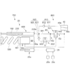
- FIG. 2 is a diagram showing a schematic configuration of the vehicle height adjusting device 700 according to the first embodiment.
- the vehicle height adjusting device 700 includes a suspension device 23 and a control device 20.
- the suspension device 23 includes a spring 500 having one end supported on the vehicle body side and the other end supported on the wheel side.
- the suspension device 23 includes a support member 551 that supports one end of the spring 500 and a jack chamber 60 that stores oil, and the support member 551 is provided in accordance with the amount of oil in the jack chamber 60.
- the jack 550 that adjusts the length of the spring 500 by moving is provided.
- the suspension device 23 also includes a reservoir chamber 40 that stores oil. Further, the suspension device 23 has a rod 150 and a cylinder 230, sucks oil into the cylinder 230 when the relative distance between the vehicle body and the wheels becomes large, and the vehicle body and the wheels are relatively moved. And a pump 600 that discharges the oil in the cylinder 230 when the distance becomes small.
- the time when the relative distance between the vehicle body and the wheel is increased is referred to as “during extension”, and the time when the relative distance between the vehicle body and the wheel is decreased is referred to as “during compression”.
- the suspension device 23 includes a switching unit 800 that switches a flow path of oil filled in the suspension device 23.
- the jack 550, the support member 551, the pump 600, the rod 150, and the cylinder 230 are, for example, the spring length changing unit 250, the upper end support member 270, and the spring length changing unit 250 described in Japanese Patent Application Laid-Open No. It can be exemplified that it is realized by the pump 600, the rod 150, and the cylinder 230.
- the switching unit 800 allows the oil to flow from the reservoir chamber 40 into the cylinder 230 but does not allow the oil to flow from the cylinder 230 into the reservoir chamber 40. It has a section 810.
- the replenishing section 810 has a refilling channel 811 which is a channel between the inlet/outlet 230 a of the cylinder 230 and the outlet 40 a of the reservoir chamber 40, and a check valve 812 provided on the refilling channel 811. ..
- the check valve 812 opens when the pressure in the reservoir chamber 40 is higher than the pressure in the cylinder 230 by a predetermined pressure or more.
- the switching unit 800 allows the oil in the jack chamber 60 to flow from the cylinder 230 into the jack chamber 60 but does not allow the oil to flow from the jack chamber 60 into the cylinder 230. It has an increasing portion 820 for increasing the amount.
- the increasing portion 820 includes an increasing/decreasing passage 821 that is a passage between the inlet/outlet 230a of the cylinder 230 and the inlet/outlet 60a of the jack chamber 60, and a check valve 822 provided on the increasing passage 821. ..
- the check valve 822 opens when the pressure in the cylinder 230 is higher than the pressure in the jack chamber 60 by a predetermined pressure or more.
- the switching unit 800 includes a first communication passage R1 through which oil flows from inside the cylinder 230 into the reservoir chamber 40, a second communication passage R2 through which oil flows from inside the jack chamber 60 into the cylinder 230, and a jack. It has a third communication passage R3 through which the oil flowing from the inside of the chamber 60 to the inside of the reservoir chamber 40 flows. Further, the switching unit 800 has a first opening/closing valve 931 for opening/closing the first communication passage R1 and a second opening/closing valve 932 for opening/closing the second communication passage R2.
- the first communication passage R1 is a flow path between the first inlet/outlet valve 931 and the inlet 40b of the reservoir chamber 40, and a first passage 941 that is a passage between the inlet/outlet 230a of the cylinder 230 and the first on/off valve 931. And a second flow path 942 which is a path.
- the second communication passage R2 includes a third flow passage 943, which is a flow passage between the inlet/outlet 60a of the jack chamber 60 and the first flow passage 941, and a first flow passage 941.
- the second opening/closing valve 932 is provided on the third flow path 943.
- the third communication passage R3 includes a third flow passage 943, a first flow passage 941 and a second flow passage 942.
- the first on-off valve 931 is a so-called normally-closed solenoid valve that closes the communication passage when the solenoid is not energized and opens the communication passage when the solenoid is energized.
- the second on-off valve 932 is a so-called normally open solenoid valve that opens the communication passage when the solenoid is not energized and closes the communication passage when the solenoid is energized.
- the first on-off valve 931 and the second on-off valve 932 are outside of a cylindrical peripheral member that covers the periphery of the jack 550 (for example, the inner tube 210 described in JP-A-2016-175555 filed by the present applicant). It is possible to exemplify that it is arranged in.
- first opening/closing valve 931 and the second opening/closing valve 932 are not particularly limited, and both the first opening/closing valve 931 and the second opening/closing valve 932 may be arranged inside the peripheral member. Further, one of the first opening/closing valve 931 and the second opening/closing valve 932 may be arranged inside the surrounding member, and the other opening/closing valve may be arranged outside the surrounding member.
- the switching unit 800 when the first opening/closing valve 931 is opened, the first flow path 941 and the second flow path 942 communicate with each other and the inside of the cylinder 230 via the first communication path R1.
- the inside of the reservoir chamber 40 communicates.
- the second opening/closing valve 932 when the second opening/closing valve 932 is opened, the inside of the jack chamber 60 and the first flow passage 941 communicate with each other, and the inside of the cylinder 230 and the inside of the jack chamber 60 communicate with each other via the second communication passage R2.
- the inside of the jack chamber 60 and the inside of the reservoir chamber 40 communicate with each other through the third communication passage R3.
- the first opening/closing valve 931 and the second opening/closing valve 932 are closed, the first communication passage R1, the second communication passage R2, and the third communication passage R3 are shut off.
- the switching unit 800 causes the first communication path R1 to communicate with the first state, the second communication path R2 to communicate with the second state, and the third communication path R3 to communicate with each other.
- the state is switched to the third state and the fourth state in which the first communication passage R1, the second communication passage R2, and the third communication passage R3 are blocked.
- the control device 20 controls switching between the first to fourth states by controlling opening/closing of the first opening/closing valve 931 and the second opening/closing valve 932.
- the control device 20 includes a CPU, a ROM in which programs executed by the CPU, various data, and the like are stored, and a RAM used as a working memory of the CPU.
- the control device 20 is supplied with output values from the detection unit 20a that detects the movement amount of the support member 551 of the jack 550, the detection unit 20b that detects the vehicle speed Vc that is the movement speed of the motorcycle 1, and the like.
- the motorcycle 1 is provided with a switch 20c in order to allow the user to select the setting of the hardness of the suspension device 23, and the control device 20 is provided with the hardness selected by the user via the switch 20c. Information is entered.
- the switch 20c is, for example, a so-called dial-type switch provided near a speedometer (not shown), and either a relatively hard setting or a relatively soft setting is set by rotating the knob by the user. Can be illustrated as being selectable.
- the switch 20c may be a so-called touch panel type switch.
- control device 20 controls opening/closing of the first opening/closing valve 931 and the second opening/closing valve 932 in accordance with the amount of movement of the support member 551, the vehicle speed Vc, and the hardness setting selected by the user via the switch 20c. To do.
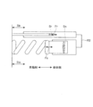
- FIG. 3 is a diagram showing an oil distribution state in the fourth state.
- a fourth state is established in which the first communication passage R1, the second communication passage R2, and the third communication passage R3 are shut off.
- the pump 600 sucks the oil stored in the reservoir chamber 40 into the cylinder 230 at the time of extension and discharges the oil in the cylinder 230 at the time of compression.
- the oil discharged from the cylinder 230 in this way opens the check valve 822 and flows into the jack chamber 60.
- the support member 551 of the jack 550 moves to the spring 500 side, and the length of the spring 500 becomes shorter.
- the spring force with which the spring 500 pushes the support member 551 becomes larger than that before the support member 551 moves to the spring 500 side.
- the vehicle height becomes higher than that before the support member 551 moves to the spring 500 side.
- FIG. 4 is a diagram showing an oil distribution state in the first state.
- the pump 600 sucks the oil stored in the reservoir chamber 40 into the cylinder 230 when it is extended, and discharges the oil inside the cylinder 230 when it is compressed.
- the oil thus discharged from the cylinder 230 flows into the reservoir chamber 40 through the first communication passage R1. Since the second on-off valve 932 is closed, oil does not flow out from the jack chamber 60, and the amount of oil in the jack chamber 60 does not increase or decrease. Therefore, the vehicle height is maintained.
- FIG. 5 is a figure which shows the circulation state of oil in a 2nd state.
- the pump 600 sucks the oil stored in the jack chamber 60 into the cylinder 230 when the pump 600 extends, and discharges the oil inside the cylinder 230 when the compressor 230 compresses.
- the oil discharged from the cylinder 230 in this way opens the check valve 822 and flows into the jack chamber 60.
- the amount of oil in the jack chamber 60 does not increase or decrease, so that the vehicle height is maintained.
- FIG. 6 is a diagram showing an oil distribution state in the third state.
- the third communication passage R3 is in communication.
- the oil stored in the jack chamber 60 flows into the reservoir chamber 40 through the third communication passage R3. This reduces the amount of oil in the jack chamber 60.
- the pump 600 sucks the oil accumulated in the jack chamber 60 into the cylinder 230 when the pressure in the jack chamber 60 is higher than the pressure in the reservoir chamber 40 at the time of extension, and the pressure inside the cylinder 230 at the time of compression. Discharge the oil.
- the oil thus discharged from the cylinder 230 flows into the reservoir chamber 40 through the first communication passage R1.
- the support member 551 of the jack 550 moves to the side opposite to the spring 500, and the length of the spring 500 becomes longer.
- the spring force with which the spring 500 pushes the support member 551 becomes smaller than that before the support member 551 moves.
- the vehicle height becomes lower than that before the support member 551 moves to the side opposite to the spring 500.
- FIG. 7 is a diagram for explaining the balance of forces generated in the suspension device 23.
- the force Fa generated in the entire suspension device 23 in the second state is calculated.
- the force acting on the rod 150 is Fr
- the force acting on the spring 500 is Fs.
- Sr is a pressure receiving area for receiving oil pressure that is a base of the force Fr acting on the rod 150
- Ss is a pressure receiving area of the supporting member 551
- a stroke amount of the rod 150 is Str
- a stroke amount of the spring 500 is Sts
- a jack 550 Let Stj be the initial stroke amount, K be the spring constant of the spring 500, and P0 be the enclosing pressure.
- the proportional constant Ka in the second state is (1+Sr/Ss) 2 times the proportional constant Ka in the first state.
- FIG. 8 is a diagram showing changes in the force Fa1 generated in the entire suspension device 23 in the first state and changes in the force Fa2 generated in the entire suspension device 23 in the second state.
- FIG. 8 is a diagram showing temporal changes in the forces Fa1 and Fa2 when the motorcycle 1 travels on a road surface in which a convex portion and a concave portion are repeatedly formed.
- Ka in the second state is (1+Sr/Ss) 2 times the proportionality constant Ka in the first state
- the suspension device 23 in the second state is used.
- the force Fa2 generated as a whole is (1+Sr/Ss) 2 times the force Fa1 generated as a whole in the suspension device 23 in the first state.
- the impact force transmitted to the vehicle body 10 is (1+Sr/Ss) 2 times larger in the second state than in the first state.
- the force pressing the wheel against the road surface is (1+Sr/Ss) 2 times greater in the second state than in the first state.
- the control device 20 sets an initial state described later, and the vehicle speed Vc rises from a state smaller than the rising vehicle speed Vu.
- the fourth state is set. After that, when the vehicle speed Vc is equal to or higher than the rising vehicle speed Vu, the fourth state is maintained until the movement amount of the support member 551 of the jack 550 reaches the target movement amount on the maximum side.
- the control device 20 determines that the movement amount of the support member 551 is the minimum target movement amount. The third state is maintained until
- the control device 20 sets the hardness selected by the user via the switch 20c after the movement amount of the support member 551 reaches the maximum target movement amount. Switch according to. The control device 20 sets the first state when the user selects the relatively soft setting, and sets the second state when the user selects the relatively hard setting.
- the initial state can be exemplified as any one of the first to third states other than the fourth state in which the vehicle height becomes high.
- the first opening/closing valve 931 is a so-called normally closed solenoid valve
- the second opening/closing valve 932 is a so-called normally open solenoid valve. Therefore, the initial state is the first opening/closing valve. It can be illustrated that the state is the same as the second state in which 931 is closed and the second opening/closing valve 932 is open.
- the controller 20 sets any one of an initial flag, a first flag, a second flag, a third flag, and a fourth flag in setting a flag set in the RAM (hereinafter, may be referred to as “flag setting”). By turning on the flag, which state the switching state is in is stored.
- the initial flag, the first flag, the second flag, the third flag, and the fourth flag are flags set in the initial state, the first state, the second state, the third state, and the fourth state, respectively. ..
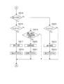
- 9 and 10 are flowcharts showing the procedure of the switching control process performed by the control device 20.
- the control device 20 repeatedly executes this switching control process every predetermined period (for example, 1 millisecond).
- the control device 20 first determines whether or not it is in the initial state (S901). This is a process in which the control device 20 determines by checking whether the initial flag is ON in the flag setting.
- the initial flag is a flag that is turned on in S921 described below.
- the control device 20 determines whether the vehicle speed Vc is equal to or higher than the ascending vehicle speed Vu (S902).
- the control device 20 switches to the fourth state to increase the vehicle height (S903). That is, the control device 20 closes the first opening/closing valve 931 and the second opening/closing valve 932. Then, the control device 20 turns on the fourth flag (S904).
- the control device 20 ends this processing.
- the control device 20 determines whether it is in the fourth state (S905). This is a process in which the control device 20 determines by checking whether or not the fourth flag is ON in the flag setting.
- the fourth flag is a flag that is turned on in S904 or S918 described below.
- the control device 20 determines whether the vehicle speed Vc is less than or equal to the descending vehicle speed Vd (S906).
- the control device 20 switches to the third state to reduce the vehicle height (S907). That is, the control device 20 opens the first opening/closing valve 931 and the second opening/closing valve 932. Then, the control device 20 turns on the third flag (S908).
- the control device 20 determines whether the movement amount of the support member 551 has reached the maximum target movement amount (S909). When it is not the target movement amount (No in S909), the control device 20 ends this processing. On the other hand, when the target movement amount is reached (Yes in S909), the control device 20 determines whether or not the user has selected a relatively hard setting via the switch 20c (S910). When the relatively hard setting is selected (Yes in S910), the control device 20 switches to the second state in order to maintain the vehicle height and set the suspension device 23 to the relatively hard setting (S911).
- the control device 20 closes the first opening/closing valve 931 and opens the second opening/closing valve 932. Then, the control device 20 turns on the second flag (S912).
- the control device 20 since the relatively soft setting is selected, the control device 20 maintains the vehicle height and makes the suspension device 23 relatively soft. The state is switched to the first state so as to be set (S913). That is, the control device 20 opens the first opening/closing valve 931 and closes the second opening/closing valve 932. Then, the control device 20 turns on the first flag (S914).
- the control device 20 determines by checking whether or not the third flag is ON in the flag setting.
- the third flag is a flag that is turned on in S908 or S924 described below.
- the control device 20 determines whether the vehicle speed Vc is equal to or higher than the rising vehicle speed Vu (S916).
- the control device 20 switches to the fourth state to increase the vehicle height (S917), and turns on the fourth flag (S918).
- the control device 20 determines whether or not the moving amount of the supporting member 551 has reached the minimum target moving amount (S919). When it is not the target movement amount (No in S919), the control device 20 ends this processing. On the other hand, when the target movement amount is reached (Yes in S919), the control device 20 switches to the initial state (S920) and turns on the initial flag (S921).
- the control device 20 switches to the third state to reduce the vehicle height (S923), and turns on the third flag (S924).
- the vehicle height adjusting device 700 configured as described above includes the spring 500, the jack 550, the reservoir chamber 40, the pump 600, the replenishing unit 810, the increasing unit 820, and the switching unit 800.
- the suspension device 23 is provided.
- the switching unit 800 switches the oil flow path to the fourth state in which the first communication passage R1, the second communication passage R2, and the third communication passage R3 are shut off, the oil in the jack chamber 60 is changed. Is increased by the increasing unit 820, the vehicle height increases.
- the replenishing unit 810 replenishes the cylinder 230 with oil.
- the switching unit 800 switches the oil flow path to the third state in which the third communication passage R3 for flowing the oil flowing from the inside of the jack chamber 60 to the inside of the reservoir chamber 40 is communicated
- the third communication passage R3 Since the oil in the jack chamber 60 reaches the reservoir chamber 40 via the, the amount of oil in the jack chamber 60 is reduced and the vehicle height is lowered.
- the vehicle height adjusting device 700 has a function of adjusting the vehicle height by increasing or decreasing the vehicle height.
- the switching unit 800 switches the oil flow path to the first state in which only the first communication passage R1 is in communication among the first communication passage R1, the second communication passage R2, and the third communication passage R3.
- the oil discharged from the cylinder 230 by the pump 600 during compression reaches the reservoir chamber 40, the oil in the jack chamber 60 does not increase or decrease. Therefore, the vehicle height is maintained.
- the cylinder 230 is replenished with oil by the replenishing unit 810 during extension.
- the switching unit 800 switches the oil flow path to the second state in which only the second communication path R2 is in communication among the first communication path R1, the second communication path R2, and the third communication path R3.
- the oil discharged from the cylinder 230 by the pump 600 during compression reaches the inside of the jack chamber 60, so that the oil in the jack chamber 60 increases.
- the oil in the jack chamber 60 is sucked into the cylinder 230, so that the oil in the jack chamber 60 is reduced. Since the amount of oil in the jack chamber 60 does not change for each compression and extension cycle, the vehicle height is maintained.
- the vehicle height adjusting device 700 has a function of maintaining the vehicle height at a desired height.
- the proportionality constant Ka in the second state is (1+Sr/Ss) 2 times the proportionality constant Ka in the first state, so that the suspension device in the second state is used.
- the hardness of 23 is (1+Sr/Ss) 2 times the hardness of the suspension device 23 in the first state. Therefore, the switching unit 800 can switch the setting of the hardness of the suspension device 23 by switching between the first state and the second state. Then, the control device 20 controls the switching by the switching unit 800 according to the hardness setting selected by the user via the switch 20c, so that the user switches the hardness setting according to the traveling situation.
- the user when traveling on a gravel road, relatively softens the hardness setting of the suspension device 23 (as the first state) to enhance the cushioning function, and for example, when traveling in an urban area, the suspension device. It is possible to change the hardness setting of 23 to be relatively hard (as the second state) so as to enhance the steering stability.
- the vehicle height adjusting device 700 including the suspension device 23 and the control device 20 allows the oil to flow into the cylinder 230 from the spring 500, the jack 550, the reservoir chamber 40, the pump 600, and the reservoir chamber 40.
- It can be regarded as a suspension system including a switching unit 800 that can switch to the second state. Therefore, even if the increase portion 820 fails and the amount of oil in the jack chamber 60 is not increased and the function of adjusting the vehicle height is impaired, the hardness setting of the suspension device 23 can be switched. is there.
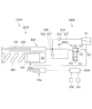
- FIG. 11 is a diagram showing a schematic configuration of a vehicle height adjusting device 2700 according to the second embodiment.
- the vehicle height adjusting device 2700 according to the second embodiment is different from the vehicle height adjusting device 700 according to the first embodiment in that it includes a suspension device 2023 instead of the suspension device 23 and replaces the control device 20.
- the difference is that a control device 2020 is provided.
- the suspension device 2023 differs from the suspension device 23 in that a switching unit 2800 is provided instead of the switching unit 800.
- the control device 2020 differs from the control device 20 in the switching control mode of the oil flow path.
- differences from the vehicle height adjusting device 700 will be described.
- parts having the same shape and function are denoted by the same reference numerals, and detailed description thereof will be omitted.
- the switching unit 2800 of the suspension device 2023 is different from the switching unit 800 according to the first embodiment in that the functions of the first opening/closing valve 931 and the second opening/closing valve 932 are carried by one solenoid valve 2930.
- the solenoid valve 2930 includes a coil (not shown), a core (not shown) disposed inside the coil, a plunger (not shown) guided by the core, and an operating rod (not shown) connected to the plunger. Is provided with a solenoid (not shown). In the solenoid, the thrust in the axial direction is generated in the plunger so that the amount of protrusion of the actuating rod from the case increases as the current supplied to the coil increases. Then, the energization amount to the coil is controlled by the control device 2020.
- the solenoid valve 2930 includes a first opening/closing valve V1 for opening/closing the first communication passage R1, a second opening/closing valve V2 for opening/closing the second communication passage R2, and a third opening/closing valve V3 for opening/closing the third communication passage R3.
- the solenoid valve 2930 opens only the second opening/closing valve V2 when the energization of the coil of the solenoid is stopped or the current is less than the first reference current, and the first communication passage R1 and the second communication passage R2 are opened. And the second state in which only the second communication passage R2 of the third communication passage R3 is in communication.
- the solenoid valve 2930 opens the third opening/closing valve V3 to connect the third communication passage R3 when the current supplied to the coil is equal to or more than the first reference current and less than the second reference current. State. Further, the solenoid valve 2930 is provided in the first communication passage R1, the second communication passage R2, and the third communication passage R3 when the energization of the coil is not less than the second reference current and less than the third reference current. , The first state in which only the first opening/closing valve V1 is opened and only the first communication passage R1 is communicated.
- the solenoid valve 2930 closes the first opening/closing valve V1, the second opening/closing valve V2, and the third opening/closing valve V3 to energize the first communication passage when the energization of the coil is the third reference current or more.
- a fourth state is established in which R1, the second communication passage R2, and the third communication passage R3 are blocked.
- the vehicle height adjusting function and the hardness of the suspension device 2023 are set similarly to the vehicle height adjusting device 700 according to the first embodiment.
- the vehicle height adjusting device 2700 may be provided with a function of switching the setting of.
- the electromagnetic valve 2930 may be arranged inside or outside a cylindrical peripheral member that covers the periphery of the jack 550.
- an electric motor and a conversion mechanism that converts rotational drive of the electric motor into movement of the working rod in the axial direction are used to move the working rod in the axial direction.
- the first opening/closing valve V1, the second opening/closing valve V2, and the third opening/closing valve V3 may be opened/closed.
- the suspension device 23 and the control device 20 according to the first embodiment, and the suspension device 2023 and the control device 2020 according to the second embodiment have a function of adjusting the vehicle height of the motorcycle 1, the suspension device 23, and the suspension device 2023.
- the control device 20 and the control device 2020 may switch the hardness setting of the suspension device 23 and the suspension device 2023 without changing the vehicle height by changing the mode of the switching control process of the oil flow path. ..
- this form will be referred to as a third embodiment.
- control device included in the suspension system according to the third embodiment does not switch to a fourth state for increasing the vehicle height and a third state for decreasing the vehicle height, and Switches to the first state or the second state according to the hardness setting selected via the switch 20c. That is, the control device provided in the suspension system according to the third embodiment sets the first state when the user selects the relatively soft setting regardless of the vehicle speed Vc, and the user relatively When the hard setting is selected, the second state is set.
- the suspension system according to the third embodiment causes oil to flow from the spring 500, the jack 550, the reservoir chamber 40, the pump 600, and the reservoir chamber 40 into the cylinder 230.
- the suspension system according to the third embodiment does not have a vehicle height adjusting function, but can realize a system having a function of switching hardness settings of the suspension device 23 and the suspension device 2023.
- the suspension system of the present invention may have a configuration in which only the hardness setting of the front fork 21 can be switched or a configuration in which only the hardness setting of the rear suspension 22 can be switched, if necessary. It is possible.
Landscapes
- Engineering & Computer Science (AREA)
- Mechanical Engineering (AREA)
- Vehicle Body Suspensions (AREA)
- Axle Suspensions And Sidecars For Cycles (AREA)
Abstract
懸架システムは、スプリング500と、スプリング500の一方の端部を支持するとともに、オイルを収容するジャッキ室60を有して、ジャッキ室60内のオイルの量に応じてスプリング500の長さを調整するジャッキ550と、オイルを貯留するリザーバ室40と、シリンダ230を有し、伸長時にはシリンダ230内にオイルを吸引し、圧縮時にはシリンダ230内のオイルを吐出するポンプ600と、リザーバ室40内からシリンダ230内にオイルを流入させ、かつ、シリンダ230内からリザーバ室40へとオイルを流入させる第1状態と、ジャッキ室60からシリンダ230内にオイルを流入させ、かつ、シリンダ230内からジャッキ室60内にオイルを流入させる第2状態とに切り替え可能な切替部800と、を備える。
Description
本発明は、懸架システム、車高調整装置に関する。
近年、自動二輪車の走行中は車高を高くし、停車中は乗り降りを楽にするために車高を低くする機能を備えた装置が提案されている。
例えば、特許文献1に記載の装置は、一端が車体側に支持され、他端が車輪側に支持されたスプリングと、液体を収容する収容室を有し、前記収容室内の液体の量に応じて前記スプリングの長さを調整する調整手段と、液体を貯留する貯留室と、を備える。また、特許文献1に記載の装置は、シリンダを有し、前記車体と前記車輪との間の相対距離が大きくなった場合には前記貯留室に溜められた液体をシリンダ内に吸引し、前記車体と前記車輪との間の相対距離が小さくなった場合にはシリンダ内の液体を吐出するポンプを備える。また、特許文献1に記載の装置は、前記収容室内の液体の量を増加させるべく前記ポンプから吐出された液体を前記収容室内に導く状態と、前記収容室内の液体の量を減少させるべく前記収容室内の液体を前記貯留室に導く状態と、前記収容室内の液体の量を保つ状態とを切り替える流路切替ユニットを備える。
例えば、特許文献1に記載の装置は、一端が車体側に支持され、他端が車輪側に支持されたスプリングと、液体を収容する収容室を有し、前記収容室内の液体の量に応じて前記スプリングの長さを調整する調整手段と、液体を貯留する貯留室と、を備える。また、特許文献1に記載の装置は、シリンダを有し、前記車体と前記車輪との間の相対距離が大きくなった場合には前記貯留室に溜められた液体をシリンダ内に吸引し、前記車体と前記車輪との間の相対距離が小さくなった場合にはシリンダ内の液体を吐出するポンプを備える。また、特許文献1に記載の装置は、前記収容室内の液体の量を増加させるべく前記ポンプから吐出された液体を前記収容室内に導く状態と、前記収容室内の液体の量を減少させるべく前記収容室内の液体を前記貯留室に導く状態と、前記収容室内の液体の量を保つ状態とを切り替える流路切替ユニットを備える。
懸架装置は、路面の凹凸を車体に伝え難くする緩衝機能と、車輪を路面に対して押さえつける機能(押さえつけ機能)とを持つことで、乗り心地や操縦安定性等を向上させる装置である。そして、懸架装置がいわゆる柔らかい設定の場合には、緩衝機能が増すことから、例えば砂利道等の凹凸が大きい道を走行する際の乗り心地が向上しやすい一方で、押さえつけ機能が低下することから操縦安定性が低下しやすい。他方、懸架装置がいわゆる硬い設定の場合には、押さえつけ機能が増すことから、例えばアスファルトが多くかつ進路を変更する機会が多い市街地を走行する際の操縦安定性が向上しやすい一方で、緩衝機能が低下することから乗り心地が低下しやすい。それゆえ、例えば砂利道等の凹凸が大きい道を走行する場合には上記柔らかい設定とし、例えば市街地を走行する場合には上記硬い設定にする等、走行状況に応じて、懸架装置の硬さの設定を切り替え可能にすることが望ましい。
本発明は、走行状況に応じて懸架装置の硬さの設定を切り替え可能にすることができる懸架システム等を提供することを目的とする。
本発明は、走行状況に応じて懸架装置の硬さの設定を切り替え可能にすることができる懸架システム等を提供することを目的とする。
本発明者らは、鋭意検討の結果、ジャッキ室内のオイルの量に応じてスプリングの長さを調整するジャッキ、を有する懸架装置において、油路の形態を機械的に変更することにより、相対的にバネ定数が小さい状態で車高を維持する第1状態と、相対的にバネ定数が大きい状態で車高を維持する第2状態とを、切り替え可能であることを知見した。第1状態と第2状態とを機械的に切り替え可能にすることにより、走行状況に応じて懸架装置の硬さの設定を切り替えることが可能な第1形態の懸架装置を提供できることを知見して、本発明を完成させた。
次に、本発明者らは、鋭意検討の結果、バネ定数が異なる上記第1状態及び第2状態を、油路の形態を機械的に変更することによって切り替え可能にする構成と、車高を高くする状態及び車高を低くする状態を油路の形態を変更することによって切り替え可能にする構成とを組み合わせた、第2形態の懸架装置を完成させた。第2形態の懸架装置は、走行中と停車中とで車高を変更可能な懸架装置に、バネ定数可変という新たな機能を付加した懸架装置である。第1形態の懸架装置及び第2形態の懸架装置によれば、バネ定数を変化させることで、車両の運動特性を変化させることができるため、路面性状に適した運動特性を選択することができる。
次に、本発明者らは、鋭意検討の結果、バネ定数が異なる上記第1状態及び第2状態を、油路の形態を機械的に変更することによって切り替え可能にする構成と、車高を高くする状態及び車高を低くする状態を油路の形態を変更することによって切り替え可能にする構成とを組み合わせた、第2形態の懸架装置を完成させた。第2形態の懸架装置は、走行中と停車中とで車高を変更可能な懸架装置に、バネ定数可変という新たな機能を付加した懸架装置である。第1形態の懸架装置及び第2形態の懸架装置によれば、バネ定数を変化させることで、車両の運動特性を変化させることができるため、路面性状に適した運動特性を選択することができる。
以下、本発明について説明する。以下の説明では、本発明の理解を容易にするために添付図面中の参照符号を括弧書きで付記するが、それによって本発明が図示の形態に限定されるものではない。
本発明は、一端が車体(10)側に支持され、他端が車輪(2)側に支持されたスプリング(500)と、前記スプリング(500)の一方の端部を支持するとともに、オイルを収容するジャッキ室(60)を有して、前記ジャッキ室(60)内のオイルの量に応じて前記スプリング(500)の長さを調整するジャッキ(550)と、オイルを貯留するリザーバ室(40)と、シリンダ(230)を有し、前記車体(10)と前記車輪(2)との間の相対距離が大きくなった場合には前記シリンダ(230)内にオイルを吸引し、前記車体(10)と前記車輪(2)との間の相対距離が小さくなった場合には前記シリンダ(230)内のオイルを吐出するポンプ(600)と、前記リザーバ室(40)内から前記シリンダ(230)内へとオイルを流入させ、かつ、前記シリンダ(230)内から前記リザーバ室(40)内へとオイルを流入させる第1状態と、前記ジャッキ室(60)から前記シリンダ(230)内へとオイルを流入させ、かつ、前記シリンダ(230)内から前記ジャッキ室(60)へとオイルを流入させる第2状態とに切り替え可能な切替部(800)と、を備える懸架システム(700)である。
ここで、前記切替部(800)は、前記シリンダ(230)内から前記リザーバ室(40)内へと向かうオイルを流す第1連通路(R1)と、前記ジャッキ室(60)内から前記シリンダ(230)内へと向かうオイルを流す第2連通路(R2)と、を有し、前記第1連通路(R1)及び前記第2連通路(R2)のいずれを連通させるかによって前記第1状態と前記第2状態とを切り替えても良い。
また、ユーザにより選択された情報に応じて、前記切替部(800)の切り替えを制御する制御部(20)をさらに備えても良い。
また、前記切替部(800)は、前記第1連通路(R1)を開閉する第1開閉弁(931)と、前記第2連通路(R2)を開閉する第2開閉弁(932)とを有し、前記制御部(20)は、前記第1開閉弁(931)及び前記第2開閉弁(932)の開閉を切り替えることで前記第1状態と前記第2状態とを切り替えても良い。
また、本発明は、一端が車体(10)側に支持され、他端が車輪(2)側に支持されたスプリング(500)と、前記スプリング(500)の一方の端部を支持するとともに、オイルを収容するジャッキ室(60)を有して、前記ジャッキ室(60)内のオイルの量に応じて前記スプリング(500)の長さを調整するジャッキ(550)と、オイルを貯留するリザーバ室(40)と、シリンダ(230)を有し、前記車体(10)と前記車輪(2)との間の相対距離が大きくなった場合には前記シリンダ(230)内にオイルを吸引し、前記車体(10)と前記車輪(2)との間の相対距離が小さくなった場合には前記シリンダ(230)内のオイルを吐出するポンプ(600)と、前記リザーバ室(40)から前記シリンダ(230)内へのオイルの流れを許容するが前記シリンダ(230)内から前記リザーバ室(40)内へのオイルの流れを許容せずに、前記シリンダ(230)内にオイルを補充させる補充部(810)と、前記シリンダ(230)内から前記ジャッキ室(60)内へのオイルの流れを許容するが前記ジャッキ室(60)内から前記シリンダ(230)内へのオイルの流れを許容せずに、前記ジャッキ室(60)内のオイルを増量させる増量部(820)と、前記シリンダ(230)内から前記リザーバ室(40)内へと向かうオイルを流す第1連通路(R1)、前記ジャッキ室(60)内から前記シリンダ(230)内へと向かうオイルを流す第2連通路(R2)、及び、前記ジャッキ室(60)内から前記リザーバ室(40)内へと向かうオイルを流す第3連通路(R3)の内、前記第1連通路(R1)のみを連通させる第1状態、前記第2連通路(R2)のみを連通させる第2状態、前記第3連通路(R3)を連通させる第3状態、及び、前記第1連通路(R1)、前記第2連通路(R2)、及び、前記第3連通路(R3)を遮断する第4状態に切り替え可能な切替部(800)と、を備える車高調整装置(700)である。
ここで、前記切替部(800)の切り替えを制御する制御部(20)を有し、前記制御部(20)は、ユーザにより選択された情報に応じて、前記第1状態又は前記第2状態に切り替えても良い。
また、前記切替部(800)は、前記第1連通路(R1)を開閉する第1開閉弁(931)と、前記第2連通路(R2)を開閉する第2開閉弁(932)とを有し、前記制御部(20)は、前記第1開閉弁(931)及び前記第2開閉弁(932)の開閉を切り替えることで前記第1状態から前記第4状態のいずれかの状態に切り替えても良い。
また、前記制御部(20)は、前記第1開閉弁(931)及び前記第2開閉弁(932)を閉じることで前記第4状態とし、前記第1開閉弁(931)及び前記第2開閉弁(932)を開くことで前記第3状態とし、前記第1開閉弁(931)を開くとともに前記第2開閉弁(932)を閉じることで前記第1状態とし、前記第1開閉弁(931)を閉じるとともに前記第2開閉弁(932)を開くことで前記第2状態としても良い。
本発明は、一端が車体(10)側に支持され、他端が車輪(2)側に支持されたスプリング(500)と、前記スプリング(500)の一方の端部を支持するとともに、オイルを収容するジャッキ室(60)を有して、前記ジャッキ室(60)内のオイルの量に応じて前記スプリング(500)の長さを調整するジャッキ(550)と、オイルを貯留するリザーバ室(40)と、シリンダ(230)を有し、前記車体(10)と前記車輪(2)との間の相対距離が大きくなった場合には前記シリンダ(230)内にオイルを吸引し、前記車体(10)と前記車輪(2)との間の相対距離が小さくなった場合には前記シリンダ(230)内のオイルを吐出するポンプ(600)と、前記リザーバ室(40)内から前記シリンダ(230)内へとオイルを流入させ、かつ、前記シリンダ(230)内から前記リザーバ室(40)内へとオイルを流入させる第1状態と、前記ジャッキ室(60)から前記シリンダ(230)内へとオイルを流入させ、かつ、前記シリンダ(230)内から前記ジャッキ室(60)へとオイルを流入させる第2状態とに切り替え可能な切替部(800)と、を備える懸架システム(700)である。
ここで、前記切替部(800)は、前記シリンダ(230)内から前記リザーバ室(40)内へと向かうオイルを流す第1連通路(R1)と、前記ジャッキ室(60)内から前記シリンダ(230)内へと向かうオイルを流す第2連通路(R2)と、を有し、前記第1連通路(R1)及び前記第2連通路(R2)のいずれを連通させるかによって前記第1状態と前記第2状態とを切り替えても良い。
また、ユーザにより選択された情報に応じて、前記切替部(800)の切り替えを制御する制御部(20)をさらに備えても良い。
また、前記切替部(800)は、前記第1連通路(R1)を開閉する第1開閉弁(931)と、前記第2連通路(R2)を開閉する第2開閉弁(932)とを有し、前記制御部(20)は、前記第1開閉弁(931)及び前記第2開閉弁(932)の開閉を切り替えることで前記第1状態と前記第2状態とを切り替えても良い。
また、本発明は、一端が車体(10)側に支持され、他端が車輪(2)側に支持されたスプリング(500)と、前記スプリング(500)の一方の端部を支持するとともに、オイルを収容するジャッキ室(60)を有して、前記ジャッキ室(60)内のオイルの量に応じて前記スプリング(500)の長さを調整するジャッキ(550)と、オイルを貯留するリザーバ室(40)と、シリンダ(230)を有し、前記車体(10)と前記車輪(2)との間の相対距離が大きくなった場合には前記シリンダ(230)内にオイルを吸引し、前記車体(10)と前記車輪(2)との間の相対距離が小さくなった場合には前記シリンダ(230)内のオイルを吐出するポンプ(600)と、前記リザーバ室(40)から前記シリンダ(230)内へのオイルの流れを許容するが前記シリンダ(230)内から前記リザーバ室(40)内へのオイルの流れを許容せずに、前記シリンダ(230)内にオイルを補充させる補充部(810)と、前記シリンダ(230)内から前記ジャッキ室(60)内へのオイルの流れを許容するが前記ジャッキ室(60)内から前記シリンダ(230)内へのオイルの流れを許容せずに、前記ジャッキ室(60)内のオイルを増量させる増量部(820)と、前記シリンダ(230)内から前記リザーバ室(40)内へと向かうオイルを流す第1連通路(R1)、前記ジャッキ室(60)内から前記シリンダ(230)内へと向かうオイルを流す第2連通路(R2)、及び、前記ジャッキ室(60)内から前記リザーバ室(40)内へと向かうオイルを流す第3連通路(R3)の内、前記第1連通路(R1)のみを連通させる第1状態、前記第2連通路(R2)のみを連通させる第2状態、前記第3連通路(R3)を連通させる第3状態、及び、前記第1連通路(R1)、前記第2連通路(R2)、及び、前記第3連通路(R3)を遮断する第4状態に切り替え可能な切替部(800)と、を備える車高調整装置(700)である。
ここで、前記切替部(800)の切り替えを制御する制御部(20)を有し、前記制御部(20)は、ユーザにより選択された情報に応じて、前記第1状態又は前記第2状態に切り替えても良い。
また、前記切替部(800)は、前記第1連通路(R1)を開閉する第1開閉弁(931)と、前記第2連通路(R2)を開閉する第2開閉弁(932)とを有し、前記制御部(20)は、前記第1開閉弁(931)及び前記第2開閉弁(932)の開閉を切り替えることで前記第1状態から前記第4状態のいずれかの状態に切り替えても良い。
また、前記制御部(20)は、前記第1開閉弁(931)及び前記第2開閉弁(932)を閉じることで前記第4状態とし、前記第1開閉弁(931)及び前記第2開閉弁(932)を開くことで前記第3状態とし、前記第1開閉弁(931)を開くとともに前記第2開閉弁(932)を閉じることで前記第1状態とし、前記第1開閉弁(931)を閉じるとともに前記第2開閉弁(932)を開くことで前記第2状態としても良い。
本発明によれば、走行状況に応じて懸架装置の硬さの設定を切り替え可能にすることができる懸架システム等を提供することができる。
以下、添付図面を参照して、本発明の実施の形態について詳細に説明する。なお、以下に示す形態は本発明の実施の形態の一例であり、本発明は、以下に示す形態に限定されない。
<第1の実施形態>
図1は、第1の実施形態に係る自動二輪車1の概略構成を示す図である。
自動二輪車1は、前側の車輪である前輪2と、後側の車輪である後輪3と、車両本体10とを備えている。車両本体10は、自動二輪車1の骨格をなす車体フレーム11と、ハンドル12と、ブレーキレバー13と、シート14等を有している。
また、自動二輪車1は、前輪2と車両本体10とを連結するフロントフォーク21を有している。また、自動二輪車1は、前輪2の左右それぞれに配置された2つのフロントフォーク21を保持する2つのブラケット15と、2つのブラケット15の間に配置されたシャフト16とを備えている。シャフト16は、車体フレーム11に回転可能に支持されている。フロントフォーク21は、路面等から前輪2に加わった衝撃を吸収する懸架スプリング21sと、懸架スプリング21sの振動を減衰する減衰装置21dとを備えている。
<第1の実施形態>
図1は、第1の実施形態に係る自動二輪車1の概略構成を示す図である。
自動二輪車1は、前側の車輪である前輪2と、後側の車輪である後輪3と、車両本体10とを備えている。車両本体10は、自動二輪車1の骨格をなす車体フレーム11と、ハンドル12と、ブレーキレバー13と、シート14等を有している。
また、自動二輪車1は、前輪2と車両本体10とを連結するフロントフォーク21を有している。また、自動二輪車1は、前輪2の左右それぞれに配置された2つのフロントフォーク21を保持する2つのブラケット15と、2つのブラケット15の間に配置されたシャフト16とを備えている。シャフト16は、車体フレーム11に回転可能に支持されている。フロントフォーク21は、路面等から前輪2に加わった衝撃を吸収する懸架スプリング21sと、懸架スプリング21sの振動を減衰する減衰装置21dとを備えている。
また、自動二輪車1は、後輪3と車両本体10とを連結するリアサスペンション22を、後輪3の左側と右側にそれぞれ1つずつ有している。リアサスペンション22は、路面等から後輪3に加わった衝撃を吸収する懸架スプリング22sと、懸架スプリング22sの振動を減衰する減衰装置22dとを備えている。
以下の説明において、フロントフォーク21とリアサスペンション22とをまとめて「懸架装置23」と称する場合もある。また、懸架スプリング21sと懸架スプリング22sとをまとめて「スプリング500」と称する場合もある。また、前輪2と後輪3とをまとめて「車輪」と称し、車両本体10を「車体」と称する場合もある。
以下の説明において、フロントフォーク21とリアサスペンション22とをまとめて「懸架装置23」と称する場合もある。また、懸架スプリング21sと懸架スプリング22sとをまとめて「スプリング500」と称する場合もある。また、前輪2と後輪3とをまとめて「車輪」と称し、車両本体10を「車体」と称する場合もある。
また、自動二輪車1は、懸架装置23内に充填されたオイルの流路の切り替えを制御することで、自動二輪車1のシート14の高さである車高を制御する制御部の一例としての制御装置20を備えている。
図2は、第1の実施形態に係る車高調整装置700の概略構成を示す図である。
図2に示すように、車高調整装置700は、懸架装置23と、制御装置20とを備えている。
懸架装置23は、一端が車体側に支持され、他端が車輪側に支持されたスプリング500を備えている。
また、懸架装置23は、スプリング500の一方の端部を支持する支持部材551と、オイルを収容するジャッキ室60とを有して、ジャッキ室60内のオイルの量に応じて支持部材551が移動することで、スプリング500の長さを調整するジャッキ550を備えている。
図2に示すように、車高調整装置700は、懸架装置23と、制御装置20とを備えている。
懸架装置23は、一端が車体側に支持され、他端が車輪側に支持されたスプリング500を備えている。
また、懸架装置23は、スプリング500の一方の端部を支持する支持部材551と、オイルを収容するジャッキ室60とを有して、ジャッキ室60内のオイルの量に応じて支持部材551が移動することで、スプリング500の長さを調整するジャッキ550を備えている。
また、懸架装置23は、オイルを貯留するリザーバ室40を備えている。
また、懸架装置23は、ロッド150とシリンダ230とを有し、車体と車輪との間の相対距離が大きくなった場合にはシリンダ230内にオイルを吸引し、車体と車輪との間の相対距離が小さくなった場合にはシリンダ230内のオイルを吐出するポンプ600と、を備えている。以下、車体と車輪との間の相対距離が大きくなった時を「伸長時」と称し、車体と車輪との間の相対距離が小さくなった時を「圧縮時」と称する場合がある。
また、懸架装置23は、懸架装置23内に充填されたオイルの流路を切り替える切替部800を備えている。
また、懸架装置23は、ロッド150とシリンダ230とを有し、車体と車輪との間の相対距離が大きくなった場合にはシリンダ230内にオイルを吸引し、車体と車輪との間の相対距離が小さくなった場合にはシリンダ230内のオイルを吐出するポンプ600と、を備えている。以下、車体と車輪との間の相対距離が大きくなった時を「伸長時」と称し、車体と車輪との間の相対距離が小さくなった時を「圧縮時」と称する場合がある。
また、懸架装置23は、懸架装置23内に充填されたオイルの流路を切り替える切替部800を備えている。
ジャッキ550、支持部材551、ポンプ600、ロッド150、シリンダ230は、それぞれ、例えば、本出願人が出願した特開2016-175555号公報に記載されたスプリング長変更ユニット250、上端部支持部材270、ポンプ600、ロッド150、シリンダ230にて実現されることを例示することができる。
切替部800は、リザーバ室40内からシリンダ230内へのオイルの流れを許容するがシリンダ230内からリザーバ室40内へのオイルの流れを許容しないことで、シリンダ230内にオイルを補充させる補充部810を有している。
補充部810は、シリンダ230の出入口230aと、リザーバ室40の出口40aとの間の流路である補充流路811と、補充流路811上に設けられたチェック弁812とを有している。チェック弁812は、リザーバ室40内の圧力がシリンダ230内の圧力よりも所定圧以上高い場合に開く。
補充部810は、シリンダ230の出入口230aと、リザーバ室40の出口40aとの間の流路である補充流路811と、補充流路811上に設けられたチェック弁812とを有している。チェック弁812は、リザーバ室40内の圧力がシリンダ230内の圧力よりも所定圧以上高い場合に開く。
また、切替部800は、シリンダ230内からジャッキ室60内へのオイルの流れを許容するがジャッキ室60内からシリンダ230内へのオイルの流れを許容しないことで、ジャッキ室60内のオイルを増量させる増量部820を有している。
増量部820は、シリンダ230の出入口230aと、ジャッキ室60の出入口60aとの間の流路である増量流路821と、増量流路821上に設けられたチェック弁822とを有している。チェック弁822は、シリンダ230内の圧力がジャッキ室60内の圧力よりも所定圧以上高い場合に開く。
増量部820は、シリンダ230の出入口230aと、ジャッキ室60の出入口60aとの間の流路である増量流路821と、増量流路821上に設けられたチェック弁822とを有している。チェック弁822は、シリンダ230内の圧力がジャッキ室60内の圧力よりも所定圧以上高い場合に開く。
また、切替部800は、シリンダ230内からリザーバ室40内へと向かうオイルを流す第1連通路R1と、ジャッキ室60内からシリンダ230内へと向かうオイルを流す第2連通路R2と、ジャッキ室60内からリザーバ室40内へと向かうオイルを流す第3連通路R3とを有している。
また、切替部800は、第1連通路R1を開閉する第1開閉弁931と、第2連通路R2を開閉する第2開閉弁932とを有する。
また、切替部800は、第1連通路R1を開閉する第1開閉弁931と、第2連通路R2を開閉する第2開閉弁932とを有する。
第1連通路R1は、シリンダ230の出入口230aと第1開閉弁931との間の流路である第1流路941と、第1開閉弁931とリザーバ室40の入口40bとの間の流路である第2流路942と、により構成される。
第2連通路R2は、ジャッキ室60の出入口60aと第1流路941との間の流路である第3流路943と、第1流路941と、により構成される。第2開閉弁932は、第3流路943上に設けられている。
第3連通路R3は、第3流路943と、第1流路941と、第2流路942と、により構成される。
第2連通路R2は、ジャッキ室60の出入口60aと第1流路941との間の流路である第3流路943と、第1流路941と、により構成される。第2開閉弁932は、第3流路943上に設けられている。
第3連通路R3は、第3流路943と、第1流路941と、第2流路942と、により構成される。
第1開閉弁931は、ソレノイドへの通電が停止している場合には連通路を閉じ、ソレノイドへ通電されている場合には連通路を開く、いわゆるノーマルクローズの電磁弁である。
第2開閉弁932は、ソレノイドへの通電が停止している場合には連通路を開き、ソレノイドへ通電されている場合には連通路を閉じる、いわゆるノーマルオープンの電磁弁である。
第1開閉弁931及び第2開閉弁932は、ジャッキ550の周囲を覆う円筒状の周囲部材(例えば、本出願人が出願した特開2016-175555号公報に記載されたインナチューブ210)の外側に配置されていることを例示することができる。ただし、第1開閉弁931、第2開閉弁932の配置位置は特に限定されず、第1開閉弁931及び第2開閉弁932がともに前記周囲部材の内側に配置されていても良い。また、第1開閉弁931及び第2開閉弁932のいずれか一方の開閉弁が前記周囲部材の内側に配置され、他方の開閉弁が前記周囲部材の外側に配置されていても良い。
第2開閉弁932は、ソレノイドへの通電が停止している場合には連通路を開き、ソレノイドへ通電されている場合には連通路を閉じる、いわゆるノーマルオープンの電磁弁である。
第1開閉弁931及び第2開閉弁932は、ジャッキ550の周囲を覆う円筒状の周囲部材(例えば、本出願人が出願した特開2016-175555号公報に記載されたインナチューブ210)の外側に配置されていることを例示することができる。ただし、第1開閉弁931、第2開閉弁932の配置位置は特に限定されず、第1開閉弁931及び第2開閉弁932がともに前記周囲部材の内側に配置されていても良い。また、第1開閉弁931及び第2開閉弁932のいずれか一方の開閉弁が前記周囲部材の内側に配置され、他方の開閉弁が前記周囲部材の外側に配置されていても良い。
第1の実施形態に係る切替部800においては、第1開閉弁931が開くと、第1流路941と第2流路942とが連通し、第1連通路R1を介してシリンダ230内とリザーバ室40内とが連通する。
また、第2開閉弁932が開くと、ジャッキ室60内と第1流路941とが連通し、第2連通路R2を介してシリンダ230内とジャッキ室60内とが連通する。
そして、第1開閉弁931と第2開閉弁932とがともに開くと、第3連通路R3を介してジャッキ室60内とリザーバ室40内とが連通する。
一方、第1開閉弁931と第2開閉弁932とがともに閉じると、第1連通路R1、第2連通路R2、及び、第3連通路R3が遮断される。
また、第2開閉弁932が開くと、ジャッキ室60内と第1流路941とが連通し、第2連通路R2を介してシリンダ230内とジャッキ室60内とが連通する。
そして、第1開閉弁931と第2開閉弁932とがともに開くと、第3連通路R3を介してジャッキ室60内とリザーバ室40内とが連通する。
一方、第1開閉弁931と第2開閉弁932とがともに閉じると、第1連通路R1、第2連通路R2、及び、第3連通路R3が遮断される。
上記構成により、第1の実施形態に係る切替部800は、第1連通路R1のみを連通させる第1状態、第2連通路R2のみを連通させる第2状態、第3連通路R3を連通させる第3状態、及び、第1連通路R1、第2連通路R2、及び、第3連通路R3を遮断する第4状態に切り替える。
制御装置20は、第1開閉弁931及び第2開閉弁932の開閉を制御することで、第1~第4状態の切り替えを制御する。制御装置20は、CPUと、CPUにて実行されるプログラムや各種データ等が記憶されたROMと、CPUの作業用メモリ等として用いられるRAMと、を備えている。制御装置20には、ジャッキ550の支持部材551の移動量を検出する検出部20a、自動二輪車1の移動速度である車速Vcを検出する検出部20b等からの出力値が入力される。
また、自動二輪車1には、懸架装置23の硬さの設定をユーザに選択可能にするためにスイッチ20cが設けられており、制御装置20には、スイッチ20cを介してユーザにより選択された硬さの情報が入力される。スイッチ20cは、例えばスピードメータ(不図示)の近傍に設けられた、例えばいわゆるダイヤル式のスイッチであり、ユーザがつまみを回転させることにより、相対的に硬い設定及び相対的に柔らかい設定のいずれかを選択可能に構成されていることを例示することができる。また、スイッチ20cは、いわゆるタッチパネル式のスイッチでも良い。
そして、制御装置20は、支持部材551の移動量、車速Vc、スイッチ20cを介してユーザにより選択された硬さの設定に応じて、第1開閉弁931及び第2開閉弁932の開閉を制御する。
また、自動二輪車1には、懸架装置23の硬さの設定をユーザに選択可能にするためにスイッチ20cが設けられており、制御装置20には、スイッチ20cを介してユーザにより選択された硬さの情報が入力される。スイッチ20cは、例えばスピードメータ(不図示)の近傍に設けられた、例えばいわゆるダイヤル式のスイッチであり、ユーザがつまみを回転させることにより、相対的に硬い設定及び相対的に柔らかい設定のいずれかを選択可能に構成されていることを例示することができる。また、スイッチ20cは、いわゆるタッチパネル式のスイッチでも良い。
そして、制御装置20は、支持部材551の移動量、車速Vc、スイッチ20cを介してユーザにより選択された硬さの設定に応じて、第1開閉弁931及び第2開閉弁932の開閉を制御する。
図3は、第4状態である場合のオイルの流通状態を示す図である。
第1開閉弁931と第2開閉弁932とがともに閉じることで、第1連通路R1、第2連通路R2、及び、第3連通路R3が遮断される第4状態となる。この第4状態においては、ポンプ600は、伸長時にはリザーバ室40内に溜められたオイルをシリンダ230内に吸引し、圧縮時にはシリンダ230内のオイルを吐出する。このようにしてシリンダ230内から吐出されたオイルは、チェック弁822を開いてジャッキ室60内に流入する。
ジャッキ室60内のオイル量が増すことによって、ジャッキ550の支持部材551がスプリング500側に移動し、スプリング500の長さが短くなる。これにより、支持部材551がスプリング500側に移動する前と比べてスプリング500が支持部材551を押すバネ力が大きくなる。その結果、支持部材551がスプリング500側に移動する前と比べて車高は高くなる。
第1開閉弁931と第2開閉弁932とがともに閉じることで、第1連通路R1、第2連通路R2、及び、第3連通路R3が遮断される第4状態となる。この第4状態においては、ポンプ600は、伸長時にはリザーバ室40内に溜められたオイルをシリンダ230内に吸引し、圧縮時にはシリンダ230内のオイルを吐出する。このようにしてシリンダ230内から吐出されたオイルは、チェック弁822を開いてジャッキ室60内に流入する。
ジャッキ室60内のオイル量が増すことによって、ジャッキ550の支持部材551がスプリング500側に移動し、スプリング500の長さが短くなる。これにより、支持部材551がスプリング500側に移動する前と比べてスプリング500が支持部材551を押すバネ力が大きくなる。その結果、支持部材551がスプリング500側に移動する前と比べて車高は高くなる。
図4は、第1状態である場合のオイルの流通状態を示す図である。
第1開閉弁931が開いて第2開閉弁932が閉じている場合には、第1連通路R1が連通され、第2連通路R2及び第3連通路R3が遮断される。この第1状態においては、ポンプ600は、伸長時にはリザーバ室40内に溜められたオイルをシリンダ230内に吸引し、圧縮時にはシリンダ230内のオイルを吐出する。このようにしてシリンダ230内から吐出されたオイルは、第1連通路R1を通ってリザーバ室40内に流入する。第2開閉弁932が閉じているので、ジャッキ室60内からオイルは流出せず、ジャッキ室60内のオイル量は増減しない。それゆえ、車高は維持される。
第1開閉弁931が開いて第2開閉弁932が閉じている場合には、第1連通路R1が連通され、第2連通路R2及び第3連通路R3が遮断される。この第1状態においては、ポンプ600は、伸長時にはリザーバ室40内に溜められたオイルをシリンダ230内に吸引し、圧縮時にはシリンダ230内のオイルを吐出する。このようにしてシリンダ230内から吐出されたオイルは、第1連通路R1を通ってリザーバ室40内に流入する。第2開閉弁932が閉じているので、ジャッキ室60内からオイルは流出せず、ジャッキ室60内のオイル量は増減しない。それゆえ、車高は維持される。
図5は、第2状態である場合のオイルの流通状態を示す図である。
第1開閉弁931が閉じて第2開閉弁932が開いている場合には、第2連通路R2が連通され、第1連通路R1及び第3連通路R3が遮断される。この第2状態においては、ポンプ600は、伸長時にはジャッキ室60内に溜められたオイルをシリンダ230内に吸引し、圧縮時にはシリンダ230内のオイルを吐出する。このようにしてシリンダ230内から吐出されたオイルは、チェック弁822を開いてジャッキ室60内に流入する。懸架装置23の伸長と圧縮とからなる1周期が終わったときには、ジャッキ室60内のオイル量は増減しないため、車高は維持される。
第1開閉弁931が閉じて第2開閉弁932が開いている場合には、第2連通路R2が連通され、第1連通路R1及び第3連通路R3が遮断される。この第2状態においては、ポンプ600は、伸長時にはジャッキ室60内に溜められたオイルをシリンダ230内に吸引し、圧縮時にはシリンダ230内のオイルを吐出する。このようにしてシリンダ230内から吐出されたオイルは、チェック弁822を開いてジャッキ室60内に流入する。懸架装置23の伸長と圧縮とからなる1周期が終わったときには、ジャッキ室60内のオイル量は増減しないため、車高は維持される。
図6は、第3状態である場合のオイルの流通状態を示す図である。
第1開閉弁931と第2開閉弁932とがともに開いている場合には、第3連通路R3が連通される。この第3状態においては、ジャッキ室60内に溜められたオイルは、第3連通路R3を通ってリザーバ室40内に流入する。これにより、ジャッキ室60内のオイル量が減少する。また、ポンプ600は、伸長時には、ジャッキ室60内の圧力がリザーバ室40内の圧力よりも高い間はジャッキ室60内に溜められたオイルをシリンダ230内に吸引し、圧縮時にはシリンダ230内のオイルを吐出する。このようにしてシリンダ230内から吐出されたオイルは、第1連通路R1を通ってリザーバ室40内に流入する。
ジャッキ室60内のオイル量が減少することによってジャッキ550の支持部材551がスプリング500とは反対側に移動し、スプリング500の長さが長くなる。これにより、支持部材551が移動する前と比べてスプリング500が支持部材551を押すバネ力が小さくなる。その結果、支持部材551がスプリング500とは反対側に移動する前と比べて車高が低くなる。
第1開閉弁931と第2開閉弁932とがともに開いている場合には、第3連通路R3が連通される。この第3状態においては、ジャッキ室60内に溜められたオイルは、第3連通路R3を通ってリザーバ室40内に流入する。これにより、ジャッキ室60内のオイル量が減少する。また、ポンプ600は、伸長時には、ジャッキ室60内の圧力がリザーバ室40内の圧力よりも高い間はジャッキ室60内に溜められたオイルをシリンダ230内に吸引し、圧縮時にはシリンダ230内のオイルを吐出する。このようにしてシリンダ230内から吐出されたオイルは、第1連通路R1を通ってリザーバ室40内に流入する。
ジャッキ室60内のオイル量が減少することによってジャッキ550の支持部材551がスプリング500とは反対側に移動し、スプリング500の長さが長くなる。これにより、支持部材551が移動する前と比べてスプリング500が支持部材551を押すバネ力が小さくなる。その結果、支持部材551がスプリング500とは反対側に移動する前と比べて車高が低くなる。
(第1状態と第2状態との差異について)
図7は、懸架装置23に生じる力のつりあいを説明するための図である。
第2状態である場合の懸架装置23全体に生じる力Faを算出する。
ロッド150に作用する力をFr、スプリング500に作用する力をFsとする。また、ロッド150に作用する力Frの基となるオイルの圧力を受ける受圧面積をSr、支持部材551における受圧面積をSs、ロッド150のストローク量をStr、スプリング500のストローク量をSts、ジャッキ550の初期ストローク量をStj、スプリング500のバネ定数をK、P0を封入圧とする。
図7は、懸架装置23に生じる力のつりあいを説明するための図である。
第2状態である場合の懸架装置23全体に生じる力Faを算出する。
ロッド150に作用する力をFr、スプリング500に作用する力をFsとする。また、ロッド150に作用する力Frの基となるオイルの圧力を受ける受圧面積をSr、支持部材551における受圧面積をSs、ロッド150のストローク量をStr、スプリング500のストローク量をSts、ジャッキ550の初期ストローク量をStj、スプリング500のバネ定数をK、P0を封入圧とする。
ロッド150の車体側へのストローク量(圧縮量)がStrである場合、スプリング500の縮み量は、Strに、ロッド150の移動に起因してジャッキ室60内に流入したオイル量に相当する分の縮み量を加えた量となるため、Sts=Str+Str×Sr/Ssとなる。
ゆえに、
Fr=Fs×Sr/Ss+Sr×P0
Fs=K×(Str×(1+Sr/Ss)+Stj)
Fa=Fr+Fs=Fs×Sr/Ss+Sr×P0+Fs
=Fs×(1+Sr/Ss)+Sr×P0
=K×(Str×(1+Sr/Ss)+Stj)×(1+Sr/Ss)+Sr×P0
=K×Str×(1+Sr/Ss)2+K×Stj×(1+Sr/Ss)+Sr×P0
となる。
従って、ロッド150の単位ストローク量当たりに懸架装置23全体に生じる力Faを示す比例定数Kaを、FaをStrにて微分することにより算出すると、
Ka=dFa/dStr=K×(1+Sr/Ss)2となる。
ゆえに、
Fr=Fs×Sr/Ss+Sr×P0
Fs=K×(Str×(1+Sr/Ss)+Stj)
Fa=Fr+Fs=Fs×Sr/Ss+Sr×P0+Fs
=Fs×(1+Sr/Ss)+Sr×P0
=K×(Str×(1+Sr/Ss)+Stj)×(1+Sr/Ss)+Sr×P0
=K×Str×(1+Sr/Ss)2+K×Stj×(1+Sr/Ss)+Sr×P0
となる。
従って、ロッド150の単位ストローク量当たりに懸架装置23全体に生じる力Faを示す比例定数Kaを、FaをStrにて微分することにより算出すると、
Ka=dFa/dStr=K×(1+Sr/Ss)2となる。
他方、第1状態である場合の懸架装置23全体に生じる力Faを算出すると、第2連通路R2は遮断されているため、ロッド150が移動したとしてもジャッキ550の支持部材551は移動しない。そのため、Sts=Strである。
ゆえに、
Fr=Sr×P0
Fs=K×(Str+Stj)
Fa=Fr+Fs=Sr×P0+K×(Str+Stj)
従って、比例定数Kaを算出すると、
Ka=dFa/dStr=Kとなる。
ゆえに、
Fr=Sr×P0
Fs=K×(Str+Stj)
Fa=Fr+Fs=Sr×P0+K×(Str+Stj)
従って、比例定数Kaを算出すると、
Ka=dFa/dStr=Kとなる。
従って、第2状態である場合の比例定数Kaは、第1状態である場合の比例定数Kaの(1+Sr/Ss)2倍となる。
図8は、第1状態である場合の懸架装置23全体に生じる力Fa1の変化と、第2状態である場合の懸架装置23全体に生じる力Fa2の変化を示す図である。
図8は、自動二輪車1が凸部と凹部とが繰り返しある路面を走行した場合の力Fa1及びFa2の時間的な変化を示す図である。
上述したように、第2状態である場合の比例定数Kaは、第1状態である場合の比例定数Kaの(1+Sr/Ss)2倍であることから、第2状態である場合の懸架装置23全体に生じる力Fa2は、第1状態である場合の懸架装置23全体に生じる力Fa1の(1+Sr/Ss)2倍となる。
それゆえ、車両本体10に伝わる衝撃力は、第1状態である場合よりも、第2状態である場合の方が(1+Sr/Ss)2倍大きくなる。同様に、車輪を路面に対して押さえつける力は、第1状態である場合よりも、第2状態である場合の方が(1+Sr/Ss)2倍大きくなる。
図8は、自動二輪車1が凸部と凹部とが繰り返しある路面を走行した場合の力Fa1及びFa2の時間的な変化を示す図である。
上述したように、第2状態である場合の比例定数Kaは、第1状態である場合の比例定数Kaの(1+Sr/Ss)2倍であることから、第2状態である場合の懸架装置23全体に生じる力Fa2は、第1状態である場合の懸架装置23全体に生じる力Fa1の(1+Sr/Ss)2倍となる。
それゆえ、車両本体10に伝わる衝撃力は、第1状態である場合よりも、第2状態である場合の方が(1+Sr/Ss)2倍大きくなる。同様に、車輪を路面に対して押さえつける力は、第1状態である場合よりも、第2状態である場合の方が(1+Sr/Ss)2倍大きくなる。
(切替制御について)
制御装置20は、自動二輪車1が走行開始後、検出部20bが検出した車速Vcが予め定められた上昇車速Vuよりも小さいときには後述する初期状態とし、車速Vcが上昇車速Vuより小さい状態から上昇車速Vu以上となった場合には、第4状態とする。以降、車速Vcが上昇車速Vu以上である場合であって、ジャッキ550の支持部材551の移動量が最大側の目標移動量となるまで第4状態とする。他方、制御装置20は、自動二輪車1が上昇車速Vu以上で走行している状態から予め定められた下降車速Vd以下となった場合には、支持部材551の移動量が最小側の目標移動量となるまで第3状態とする。
制御装置20は、自動二輪車1が走行開始後、検出部20bが検出した車速Vcが予め定められた上昇車速Vuよりも小さいときには後述する初期状態とし、車速Vcが上昇車速Vuより小さい状態から上昇車速Vu以上となった場合には、第4状態とする。以降、車速Vcが上昇車速Vu以上である場合であって、ジャッキ550の支持部材551の移動量が最大側の目標移動量となるまで第4状態とする。他方、制御装置20は、自動二輪車1が上昇車速Vu以上で走行している状態から予め定められた下降車速Vd以下となった場合には、支持部材551の移動量が最小側の目標移動量となるまで第3状態とする。
制御装置20は、車速Vcが上昇車速Vu以上である場合であって、支持部材551の移動量が最大側の目標移動量となった後、ユーザがスイッチ20cを介して選択した硬さの設定に応じて切り替える。制御装置20は、ユーザが相対的に柔らかい設定を選択している場合には第1状態とし、ユーザが相対的に硬い設定を選択している場合には第2状態とする。
なお、上昇車速Vuは10km/h、下降車速Vdは8km/hであることを例示することができる。また、最大側の目標移動量は100(mm)、最小側の目標移動量は0(mm)であることを例示することができる。目標移動量は、ユーザの選択により変更しても良い。また、初期状態は、車高が高くなる第4状態以外の、第1状態~第3状態のいずれか一の状態であることを例示することができる。第1の実施形態においては、第1開閉弁931が、いわゆるノーマルクローズの電磁弁であり、第2開閉弁932が、いわゆるノーマルオープンの電磁弁であることから、初期状態は、第1開閉弁931が閉、第2開閉弁932が開の状態である第2状態と同じ状態であることを例示することができる。
制御装置20は、RAMにセットされるフラグの設定(以下、「フラグ設定」と称する場合がある)において、初期フラグ、第1フラグ、第2フラグ、第3フラグ、第4フラグのいずれかのフラグをONにすることで、切替状態がいずれの状態であるかを記憶する。初期フラグ、第1フラグ、第2フラグ、第3フラグ、第4フラグは、それぞれ、初期状態、第1状態、第2状態、第3状態、第4状態である場合にセットされるフラグである。
次に、フローチャートを用いて、制御装置20が行う切替制御処理の手順について説明する。
図9及び図10は、制御装置20が行う切替制御処理の手順を示すフローチャートである。
制御装置20は、この切替制御処理を、予め定めた期間(例えば1ミリ秒)毎に繰り返し実行する。
図9及び図10は、制御装置20が行う切替制御処理の手順を示すフローチャートである。
制御装置20は、この切替制御処理を、予め定めた期間(例えば1ミリ秒)毎に繰り返し実行する。
制御装置20は、先ず、初期状態であるか否かを判定する(S901)。これは、制御装置20が、フラグ設定において初期フラグがONであるか否か確認することにより判定する処理である。初期フラグは、後述するS921にてONにされるフラグである。初期状態である場合(S901でYes)、制御装置20は、車速Vcが上昇車速Vu以上であるか否かを判定する(S902)。車速Vcが上昇車速Vu以上である場合(S902でYes)、制御装置20は、車高を高めるべく第4状態に切り替える(S903)。つまり、制御装置20は、第1開閉弁931及び第2開閉弁932を閉じる。そして、制御装置20は、第4フラグをONにする(S904)。他方、車速Vcが上昇車速Vu以上ではない場合(S902でNo)、制御装置20は、本処理を終了する。
初期状態ではない場合(S902でNo)、制御装置20は、第4状態であるか否かを判定する(S905)。これは、制御装置20が、フラグ設定において第4フラグがONであるか否か確認することにより判定する処理である。第4フラグは、S904、又は、後述するS918にてONにされるフラグである。第4状態である場合(S905でYes)、制御装置20は、車速Vcが下降車速Vd以下であるか否かを判定する(S906)。車速Vcが下降車速Vd以下である場合(S906でYes)、制御装置20は、車高を低下させるべく第3状態に切り替える(S907)。つまり、制御装置20は、第1開閉弁931及び第2開閉弁932を開く。そして、制御装置20は、第3フラグをONにする(S908)。
車速Vcが下降車速Vd以下ではない場合(S906でNo)、制御装置20は、支持部材551の移動量が最大側の目標移動量となったか否かを判定する(S909)。目標移動量となっていない場合(S909でNo)、制御装置20は、本処理を終了する。他方、目標移動量となった場合(S909でYes)、制御装置20は、ユーザによりスイッチ20cを介して相対的に硬い設定が選択されているか否かを判定する(S910)。相対的に硬い設定が選択されている場合(S910でYes)、制御装置20は、車高を維持するとともに懸架装置23を相対的に硬い設定にするべく第2状態に切り替える(S911)。つまり、制御装置20は、第1開閉弁931を閉じ、第2開閉弁932を開く。そして、制御装置20は、第2フラグをONにする(S912)。他方、相対的に硬い設定が選択されていない場合(S910でNo)、相対的に柔らかい設定が選択されているので、制御装置20は、車高を維持するとともに懸架装置23を相対的に柔らかい設定にするべく第1状態に切り替える(S913)。つまり、制御装置20は、第1開閉弁931を開き、第2開閉弁932を閉じる。そして、制御装置20は、第1フラグをONにする(S914)。
第4状態ではない場合(S905でNo)、第3状態であるか否かを判定する(S915)。これは、制御装置20が、フラグ設定において第3フラグがONであるか否か確認することにより判定する処理である。第3フラグは、S908、又は、後述するS924にてONにされるフラグである。第3状態である場合(S915でYes)、制御装置20は、車速Vcが上昇車速Vu以上であるか否かを判定する(S916)。車速Vcが上昇車速Vu以上である場合(S916でYes)、制御装置20は、車高を高めるべく第4状態に切り替え(S917)、第4フラグをONにする(S918)。
車速Vcが上昇車速Vu以上ではない場合(S916でNo)、制御装置20は、支持部材551の移動量が最小側の目標移動量となったか否かを判定する(S919)。目標移動量となっていない場合(S919でNo)、制御装置20は、本処理を終了する。他方、目標移動量となった場合(S919でYes)、制御装置20は、初期状態に切り替え(S920)、初期フラグをONにする(S921)。
第3状態ではない場合(S915でNo)、第1状態又は第2状態であるので、車速Vcが下降車速Vd以下であるか否かを判定する(S922)。車速Vcが下降車速Vd以下である場合(S922でYes)、制御装置20は、車高を低下させるべく第3状態に切り替え(S923)、第3フラグをONにする(S924)。
以上のように構成された車高調整装置700は、スプリング500と、ジャッキ550と、リザーバ室40と、ポンプ600と、補充部810と、増量部820と、切替部800と、を有している懸架装置23を備える。そして、切替部800が、第1連通路R1、第2連通路R2、及び、第3連通路R3を遮断する第4状態にオイルの流路を切り替えた場合には、ジャッキ室60内のオイルの量が増量部820により増量されるため、車高が高くなる。この第4状態である場合、補充部810により、シリンダ230内へオイルが補充される。他方、切替部800が、ジャッキ室60内からリザーバ室40内へと向かうオイルを流す第3連通路R3を連通させる第3状態にオイルの流路を切り替えた場合には、第3連通路R3を介して、ジャッキ室60内のオイルがリザーバ室40内に至るので、ジャッキ室60内のオイルの量が減り、車高が低くなる。このように、車高調整装置700は、車高を高めたり、低めたりして、車高を調整する機能を有する。
また、切替部800が、第1連通路R1、第2連通路R2、及び、第3連通路R3の内、第1連通路R1のみを連通させる第1状態にオイルの流路を切り替えた場合には、圧縮時にポンプ600によりシリンダ230内から吐出されたオイルは、リザーバ室40内に至るので、ジャッキ室60内のオイルは増減しない。それゆえ、車高が維持される。なお、この第1状態である場合、伸長時には、補充部810により、シリンダ230内にオイルが補充される。
また、切替部800が、第1連通路R1、第2連通路R2、及び、第3連通路R3の内、第2連通路R2のみを連通させる第2状態にオイルの流路を切り替えた場合には、圧縮時にポンプ600によりシリンダ230内から吐出されたオイルは、ジャッキ室60内に至るので、ジャッキ室60内のオイルは増える。他方、伸長時には、ジャッキ室60内のオイルがシリンダ230内に吸引されるので、ジャッキ室60内のオイルは減る。圧縮及び伸長の1周期毎にジャッキ室60内のオイル量を比べると変化しないため、車高は維持される。
このように、車高調整装置700は、車高を所望の高さに維持する機能を有する。
また、切替部800が、第1連通路R1、第2連通路R2、及び、第3連通路R3の内、第2連通路R2のみを連通させる第2状態にオイルの流路を切り替えた場合には、圧縮時にポンプ600によりシリンダ230内から吐出されたオイルは、ジャッキ室60内に至るので、ジャッキ室60内のオイルは増える。他方、伸長時には、ジャッキ室60内のオイルがシリンダ230内に吸引されるので、ジャッキ室60内のオイルは減る。圧縮及び伸長の1周期毎にジャッキ室60内のオイル量を比べると変化しないため、車高は維持される。
このように、車高調整装置700は、車高を所望の高さに維持する機能を有する。
また、上述したように、第2状態である場合の比例定数Kaは、第1状態である場合の比例定数Kaの(1+Sr/Ss)2倍であるので、第2状態である場合の懸架装置23の硬さは、第1状態である場合の懸架装置23の硬さの(1+Sr/Ss)2倍となる。それゆえ、切替部800が、第1状態と第2状態とを切り替えることで、懸架装置23の硬さの設定を切り替えることが可能になっている。そして、ユーザがスイッチ20cを介して選択した硬さの設定に応じて、制御装置20が、切替部800による切り替えを制御することで、ユーザは、走行状況に応じて硬さの設定を切り替えることができる。ユーザは、例えば砂利道を走行する際には、懸架装置23の硬さの設定を相対的に柔らかくして(第1状態として)緩衝機能を高め、例えば市街地を走行する際には、懸架装置23の硬さの設定を相対的に硬くして(第2状態として)操縦安定性を高めるように切り替えることが可能である。
なお、懸架装置23及び制御装置20を有する車高調整装置700は、スプリング500と、ジャッキ550と、リザーバ室40と、ポンプ600と、リザーバ室40内からシリンダ230内へとオイルを流入させ、かつ、シリンダ230内からリザーバ室40内へとオイルを流入させる第1状態と、ジャッキ室60からシリンダ230内へとオイルを流入させ、かつ、シリンダ230内からジャッキ室60へとオイルを流入させる第2状態とに切り替え可能な切替部800と、を備える懸架システムとして捉えることが可能である。それゆえ、仮に増量部820が故障してジャッキ室60内のオイルの量が増量されなくなり車高を調整する機能が損なわれたとしても、懸架装置23の硬さの設定を切り替えることは可能である。
<第2の実施形態>
図11は、第2の実施形態に係る車高調整装置2700の概略構成を示す図である。
第2の実施形態に係る車高調整装置2700は、第1の実施形態に係る車高調整装置700に対して、上記懸架装置23に代えて、懸架装置2023を備え、上記制御装置20に代えて、制御装置2020を備えている点が異なる。懸架装置2023は、懸架装置23に対して、切替部800に代えて、切替部2800を備えている点が異なる。制御装置2020は、制御装置20に対して、オイルの流路の切替制御態様が異なる。以下、車高調整装置700と異なる点について説明する。車高調整装置2700と車高調整装置700とで、同じ形状、機能を有する部位については同じ符号を付し、その詳細な説明は省略する。
図11は、第2の実施形態に係る車高調整装置2700の概略構成を示す図である。
第2の実施形態に係る車高調整装置2700は、第1の実施形態に係る車高調整装置700に対して、上記懸架装置23に代えて、懸架装置2023を備え、上記制御装置20に代えて、制御装置2020を備えている点が異なる。懸架装置2023は、懸架装置23に対して、切替部800に代えて、切替部2800を備えている点が異なる。制御装置2020は、制御装置20に対して、オイルの流路の切替制御態様が異なる。以下、車高調整装置700と異なる点について説明する。車高調整装置2700と車高調整装置700とで、同じ形状、機能を有する部位については同じ符号を付し、その詳細な説明は省略する。
懸架装置2023の切替部2800は、第1の実施形態に係る切替部800に対して、第1開閉弁931及び第2開閉弁932の機能を、1つの電磁弁2930にて担う点が異なる。
電磁弁2930は、コイル(不図示)と、コイルの内側に配置されたコア(不図示)と、コアに案内されるプランジャ(不図示)と、プランジャに連結された作動ロッド(不図示)とを有するソレノイド(不図示)を備えている。ソレノイドは、コイルへの通電電流が大きくなるほど作動ロッドのケースからの突出量が大きくなるように、プランジャに軸方向の推力が発生する。そして、コイルへの通電量は制御装置2020にて制御される。
電磁弁2930は、コイル(不図示)と、コイルの内側に配置されたコア(不図示)と、コアに案内されるプランジャ(不図示)と、プランジャに連結された作動ロッド(不図示)とを有するソレノイド(不図示)を備えている。ソレノイドは、コイルへの通電電流が大きくなるほど作動ロッドのケースからの突出量が大きくなるように、プランジャに軸方向の推力が発生する。そして、コイルへの通電量は制御装置2020にて制御される。
電磁弁2930は、第1連通路R1を開閉する第1開閉弁V1と、第2連通路R2を開閉する第2開閉弁V2と、第3連通路R3を開閉する第3開閉弁V3とを有する。そして、電磁弁2930は、ソレノイドのコイルへの通電が停止されているか第1基準電流未満である場合には、第2開閉弁V2のみを開いて、第1連通路R1、第2連通路R2及び第3連通路R3の内、第2連通路R2のみを連通させる第2状態とする。また、電磁弁2930は、コイルへの通電が第1基準電流以上であって第2基準電流未満である場合には、第3開閉弁V3を開いて、第3連通路R3を連通させる第3状態とする。また、電磁弁2930は、コイルへの通電が第2基準電流以上であって第3基準電流未満である場合には、第1連通路R1、第2連通路R2及び第3連通路R3の内、第1開閉弁V1のみを開いて、第1連通路R1のみを連通させる第1状態とする。また、電磁弁2930は、コイルへの通電が第3基準電流以上である場合には、第1開閉弁V1、第2開閉弁V2、及び、第3開閉弁V3を閉じて、第1連通路R1、第2連通路R2、及び、第3連通路R3を遮断する第4状態とする。
このように、1つの電磁弁2930を用いて、オイルの流路を切り替えても、第1の実施形態に係る車高調整装置700と同様に、車高調整機能と、懸架装置2023の硬さの設定を切り替える機能とを備えた車高調整装置2700とすることができる。
なお、電磁弁2930は、ジャッキ550の周囲を覆う円筒状の周囲部材の内側に配置されていても良いし、外側に配置されていても良い。
また、電磁弁2930の代わりに、例えば、電動モータ、及び、この電動モータの回転駆動を上記作動ロッドの軸方向の移動に変換する変換機構を用いて、作動ロッドを軸方向に移動させることで、第1開閉弁V1、第2開閉弁V2、及び、第3開閉弁V3を開閉しても良い。
なお、電磁弁2930は、ジャッキ550の周囲を覆う円筒状の周囲部材の内側に配置されていても良いし、外側に配置されていても良い。
また、電磁弁2930の代わりに、例えば、電動モータ、及び、この電動モータの回転駆動を上記作動ロッドの軸方向の移動に変換する変換機構を用いて、作動ロッドを軸方向に移動させることで、第1開閉弁V1、第2開閉弁V2、及び、第3開閉弁V3を開閉しても良い。
<切替制御処理の変形例>
第1の実施形態に係る懸架装置23及び制御装置20、第2の実施形態に係る懸架装置2023及び制御装置2020は、自動二輪車1の車高を調整する機能と、懸架装置23、懸架装置2023の硬さの設定を変更可能な機能とを備えているが、特にかかる態様に限定されない。制御装置20、制御装置2020は、オイルの流路の切替制御処理の態様を変更することで、車高を調整することなく、懸架装置23、懸架装置2023の硬さの設定を切り替えても良い。以下において、当該形態を、第3の実施形態と称する。
第1の実施形態に係る懸架装置23及び制御装置20、第2の実施形態に係る懸架装置2023及び制御装置2020は、自動二輪車1の車高を調整する機能と、懸架装置23、懸架装置2023の硬さの設定を変更可能な機能とを備えているが、特にかかる態様に限定されない。制御装置20、制御装置2020は、オイルの流路の切替制御処理の態様を変更することで、車高を調整することなく、懸架装置23、懸架装置2023の硬さの設定を切り替えても良い。以下において、当該形態を、第3の実施形態と称する。
より具体的には、上記第3の実施形態に係る懸架システムに備えられる制御装置は、車高を高めるための第4状態、及び、車高を低めるための第3状態に切り替えずに、ユーザがスイッチ20cを介して選択した硬さの設定に応じて、第1状態又は第2状態に切り替える。すなわち、上記第3の実施形態に係る懸架システムに備えられる制御装置は、車速Vcに関わらず、ユーザが相対的に柔らかい設定を選択している場合には第1状態とし、ユーザが相対的に硬い設定を選択している場合には第2状態とする。
上記のように制御することで、上記第3の実施形態に係る懸架システムは、スプリング500と、ジャッキ550と、リザーバ室40と、ポンプ600と、リザーバ室40内からシリンダ230内へとオイルを流入させ、かつ、シリンダ230内からリザーバ室40内へとオイルを流入させる第1状態と、ジャッキ室60からシリンダ230内へとオイルを流入させ、かつ、シリンダ230内からジャッキ室60へとオイルを流入させる第2状態とに切り替え可能な切替部800、2800と、を備える懸架システムとして捉えることが可能である。第3の実施形態に係る懸架システムは、車高調整機能を備えないが、懸架装置23、懸架装置2023の硬さの設定を切り替える機能を備えたシステムを実現できる。
上記説明では、フロントフォーク21とリアサスペンション22とをまとめて懸架装置23と称していた。そのため、フロントフォーク21及びリアサスペンション22の両方に対して、硬さの設定を切り替えることが可能な懸架システムについて説明した。しかし、本発明は、当該形態に限定されない。本発明の懸架システムは、必要に応じて、フロントフォーク21の硬さの設定のみを切り替えることが可能な形態や、リアサスペンション22の硬さの設定のみを切り替えることが可能な形態にすることも可能である。
1…自動二輪車、2…前輪、3…後輪、20,2020…制御装置、21…フロントフォーク、22…リアサスペンション、23,2023…懸架装置、40…リザーバ室、60…ジャッキ室、500…スプリング、550…ジャッキ、600…ポンプ、700,2700…切替部、800,2800…切替部、931…第1開閉弁、932…第2開閉弁
Claims (8)
- 一端が車体側に支持され、他端が車輪側に支持されたスプリングと、
前記スプリングの一方の端部を支持するとともに、オイルを収容するジャッキ室を有して、前記ジャッキ室内のオイルの量に応じて前記スプリングの長さを調整するジャッキと、
オイルを貯留するリザーバ室と、
シリンダを有し、前記車体と前記車輪との間の相対距離が大きくなった場合には前記シリンダ内にオイルを吸引し、前記車体と前記車輪との間の相対距離が小さくなった場合には前記シリンダ内のオイルを吐出するポンプと、
前記リザーバ室内から前記シリンダ内へとオイルを流入させ、かつ、前記シリンダ内から前記リザーバ室内へとオイルを流入させる第1状態と、前記ジャッキ室から前記シリンダ内へとオイルを流入させ、かつ、前記シリンダ内から前記ジャッキ室へとオイルを流入させる第2状態とに切り替え可能な切替部と、
を備える懸架システム。 - 前記切替部は、前記シリンダから前記リザーバ室内へと向かうオイルを流す第1連通路と、前記ジャッキ室内から前記シリンダ内へと向かうオイルを流す第2連通路と、を有し、前記第1連通路及び前記第2連通路のいずれを連通させるかによって前記第1状態と前記第2状態とを切り替える
請求項1に記載の懸架システム。 - ユーザにより選択された情報に応じて、前記切替部の切り替えを制御する制御部をさらに備える
請求項1又は2に記載の懸架システム。 - 前記切替部は、前記第1連通路を開閉する第1開閉弁と、前記第2連通路を開閉する第2開閉弁とを有し、
前記制御部は、前記第1開閉弁及び前記第2開閉弁の開閉を切り替えることで前記第1状態と前記第2状態とを切り替える
請求項3に記載の懸架システム。 - 一端が車体側に支持され、他端が車輪側に支持されたスプリングと、
前記スプリングの一方の端部を支持するとともに、オイルを収容するジャッキ室を有して、前記ジャッキ室内のオイルの量に応じて前記スプリングの長さを調整するジャッキと、
オイルを貯留するリザーバ室と、
シリンダを有し、前記車体と前記車輪との間の相対距離が大きくなった場合には前記シリンダ内にオイルを吸引し、前記車体と前記車輪との間の相対距離が小さくなった場合には前記シリンダ内のオイルを吐出するポンプと、
前記リザーバ室から前記シリンダ内へのオイルの流れを許容するが前記シリンダ内から前記リザーバ室内へのオイルの流れを許容せずに、前記シリンダ内にオイルを補充させる補充部と、
前記シリンダ内から前記ジャッキ室内へのオイルの流れを許容するが前記ジャッキ室内から前記シリンダ内へのオイルの流れを許容せずに、前記ジャッキ室内のオイルを増量させる増量部と、
前記シリンダ内から前記リザーバ室内へと向かうオイルを流す第1連通路、前記ジャッキ室内から前記シリンダ内へと向かうオイルを流す第2連通路、及び、前記ジャッキ室内から前記リザーバ室内へと向かうオイルを流す第3連通路の内、前記第1連通路のみを連通させる第1状態、前記第2連通路のみを連通させる第2状態、前記第3連通路を連通させる第3状態、及び、前記第1連通路、前記第2連通路、及び、前記第3連通路を遮断する第4状態に切り替え可能な切替部と、
を備える車高調整装置。 - 前記切替部の切り替えを制御する制御部を有し、
前記制御部は、ユーザにより選択された情報に応じて、前記第1状態又は前記第2状態に切り替える
請求項5に記載の車高調整装置。 - 前記切替部は、前記第1連通路を開閉する第1開閉弁と、前記第2連通路を開閉する第2開閉弁とを有し、
前記制御部は、前記第1開閉弁及び前記第2開閉弁の開閉を切り替えることで前記第1状態から前記第4状態のいずれかの状態に切り替える
請求項6に記載の車高調整装置。 - 前記制御部は、前記第1開閉弁及び前記第2開閉弁を閉じることで前記第4状態とし、前記第1開閉弁及び前記第2開閉弁を開くことで前記第3状態とし、前記第1開閉弁を開くとともに前記第2開閉弁を閉じることで前記第1状態とし、前記第1開閉弁を閉じるとともに前記第2開閉弁を開くことで前記第2状態とする
請求項7に記載の車高調整装置。
Priority Applications (2)
| Application Number | Priority Date | Filing Date | Title |
|---|---|---|---|
| PCT/JP2018/045510 WO2020121408A1 (ja) | 2018-12-11 | 2018-12-11 | 懸架システム、車高調整装置 |
| JP2018565070A JPWO2020121408A1 (ja) | 2018-12-11 | 2018-12-11 | 懸架システム、車高調整装置 |
Applications Claiming Priority (1)
| Application Number | Priority Date | Filing Date | Title |
|---|---|---|---|
| PCT/JP2018/045510 WO2020121408A1 (ja) | 2018-12-11 | 2018-12-11 | 懸架システム、車高調整装置 |
Publications (1)
| Publication Number | Publication Date |
|---|---|
| WO2020121408A1 true WO2020121408A1 (ja) | 2020-06-18 |
Family
ID=71077189
Family Applications (1)
| Application Number | Title | Priority Date | Filing Date |
|---|---|---|---|
| PCT/JP2018/045510 Ceased WO2020121408A1 (ja) | 2018-12-11 | 2018-12-11 | 懸架システム、車高調整装置 |
Country Status (2)
| Country | Link |
|---|---|
| JP (1) | JPWO2020121408A1 (ja) |
| WO (1) | WO2020121408A1 (ja) |
Citations (3)
| Publication number | Priority date | Publication date | Assignee | Title |
|---|---|---|---|---|
| JPH10157435A (ja) * | 1996-11-27 | 1998-06-16 | Toyota Motor Corp | ばね力変更装置 |
| JPH1191331A (ja) * | 1997-09-19 | 1999-04-06 | Toyota Motor Corp | サスペンション装置 |
| JP2014058260A (ja) * | 2012-09-18 | 2014-04-03 | Showa Corp | 自動二輪車の車高調整装置 |
-
2018
- 2018-12-11 JP JP2018565070A patent/JPWO2020121408A1/ja active Pending
- 2018-12-11 WO PCT/JP2018/045510 patent/WO2020121408A1/ja not_active Ceased
Patent Citations (3)
| Publication number | Priority date | Publication date | Assignee | Title |
|---|---|---|---|---|
| JPH10157435A (ja) * | 1996-11-27 | 1998-06-16 | Toyota Motor Corp | ばね力変更装置 |
| JPH1191331A (ja) * | 1997-09-19 | 1999-04-06 | Toyota Motor Corp | サスペンション装置 |
| JP2014058260A (ja) * | 2012-09-18 | 2014-04-03 | Showa Corp | 自動二輪車の車高調整装置 |
Also Published As
| Publication number | Publication date |
|---|---|
| JPWO2020121408A1 (ja) | 2021-02-15 |
Similar Documents
| Publication | Publication Date | Title |
|---|---|---|
| JP5938057B2 (ja) | 車高調整装置、車高調整装置用の制御装置およびプログラム | |
| CN104443212B (zh) | 车辆高度调节装置及车辆高度调节方法 | |
| JP6180964B2 (ja) | 車高調整装置 | |
| JP6193158B2 (ja) | 車高調整装置、車高調整方法 | |
| EP1669283B1 (en) | Front fork | |
| JP5947320B2 (ja) | 車高調整装置、車高調整方法 | |
| US6702075B2 (en) | Controllable shock absorber | |
| US20190001776A1 (en) | Vehicle height adjustment device | |
| JPH02106419A (ja) | 自動車の車高調整装置 | |
| CN113498396A (zh) | 缓冲器 | |
| KR101162307B1 (ko) | 감쇠력 가변식 쇽업소버 | |
| JP4546308B2 (ja) | 可変減衰力ダンパーの制御装置 | |
| JP6873355B1 (ja) | 懸架装置、車高調整装置、および鞍乗型車両 | |
| WO2020121408A1 (ja) | 懸架システム、車高調整装置 | |
| JP2006151161A (ja) | エアバネおよび懸架装置 | |
| JP7308377B1 (ja) | 緩衝器 | |
| JPH1113820A (ja) | 車両用ショックアブソーバ | |
| KR20090100488A (ko) | 감쇠력 가변 밸브 | |
| JP2000185536A (ja) | エアサスペンション用油圧緩衝器 | |
| JPH02102942A (ja) | 油圧緩衝器の制御装置 | |
| JPH1191331A (ja) | サスペンション装置 | |
| JP4683612B2 (ja) | 懸架装置 | |
| KR20160053567A (ko) | 자동차 현가용 스텝바 장치 | |
| JPS62152911A (ja) | 車両の緩衝装置 | |
| JPH048614A (ja) | 減衰器の減衰力制御装置 |
Legal Events
| Date | Code | Title | Description |
|---|---|---|---|
| ENP | Entry into the national phase |
Ref document number: 2018565070 Country of ref document: JP Kind code of ref document: A |
|
| 121 | Ep: the epo has been informed by wipo that ep was designated in this application |
Ref document number: 18943276 Country of ref document: EP Kind code of ref document: A1 |
|
| NENP | Non-entry into the national phase |
Ref country code: DE |
|
| 122 | Ep: pct application non-entry in european phase |
Ref document number: 18943276 Country of ref document: EP Kind code of ref document: A1 |