WO2020116378A1 - 流路抵抗体、及び熱交換器 - Google Patents
流路抵抗体、及び熱交換器 Download PDFInfo
- Publication number
- WO2020116378A1 WO2020116378A1 PCT/JP2019/046969 JP2019046969W WO2020116378A1 WO 2020116378 A1 WO2020116378 A1 WO 2020116378A1 JP 2019046969 W JP2019046969 W JP 2019046969W WO 2020116378 A1 WO2020116378 A1 WO 2020116378A1
- Authority
- WO
- WIPO (PCT)
- Prior art keywords
- plate
- flow path
- cooling water
- outer frame
- frame member
- Prior art date
- Legal status (The legal status is an assumption and is not a legal conclusion. Google has not performed a legal analysis and makes no representation as to the accuracy of the status listed.)
- Ceased
Links
Images











Classifications
-
- F—MECHANICAL ENGINEERING; LIGHTING; HEATING; WEAPONS; BLASTING
- F28—HEAT EXCHANGE IN GENERAL
- F28F—DETAILS OF HEAT-EXCHANGE AND HEAT-TRANSFER APPARATUS, OF GENERAL APPLICATION
- F28F13/00—Arrangements for modifying heat-transfer, e.g. increasing, decreasing
- F28F13/06—Arrangements for modifying heat-transfer, e.g. increasing, decreasing by affecting the pattern of flow of the heat-exchange media
- F28F13/12—Arrangements for modifying heat-transfer, e.g. increasing, decreasing by affecting the pattern of flow of the heat-exchange media by creating turbulence, e.g. by stirring, by increasing the force of circulation
-
- F—MECHANICAL ENGINEERING; LIGHTING; HEATING; WEAPONS; BLASTING
- F15—FLUID-PRESSURE ACTUATORS; HYDRAULICS OR PNEUMATICS IN GENERAL
- F15D—FLUID DYNAMICS, i.e. METHODS OR MEANS FOR INFLUENCING THE FLOW OF GASES OR LIQUIDS
- F15D1/00—Influencing flow of fluids
- F15D1/02—Influencing flow of fluids in pipes or conduits
- F15D1/025—Influencing flow of fluids in pipes or conduits by means of orifice or throttle elements
-
- F—MECHANICAL ENGINEERING; LIGHTING; HEATING; WEAPONS; BLASTING
- F15—FLUID-PRESSURE ACTUATORS; HYDRAULICS OR PNEUMATICS IN GENERAL
- F15D—FLUID DYNAMICS, i.e. METHODS OR MEANS FOR INFLUENCING THE FLOW OF GASES OR LIQUIDS
- F15D1/00—Influencing flow of fluids
- F15D1/02—Influencing flow of fluids in pipes or conduits
- F15D1/06—Influencing flow of fluids in pipes or conduits by influencing the boundary layer
- F15D1/065—Whereby an element is dispersed in a pipe over the whole length or whereby several elements are regularly distributed in a pipe
-
- F—MECHANICAL ENGINEERING; LIGHTING; HEATING; WEAPONS; BLASTING
- F28—HEAT EXCHANGE IN GENERAL
- F28D—HEAT-EXCHANGE APPARATUS, NOT PROVIDED FOR IN ANOTHER SUBCLASS, IN WHICH THE HEAT-EXCHANGE MEDIA DO NOT COME INTO DIRECT CONTACT
- F28D7/00—Heat-exchange apparatus having stationary tubular conduit assemblies for both heat-exchange media, the media being in contact with different sides of a conduit wall
- F28D7/06—Heat-exchange apparatus having stationary tubular conduit assemblies for both heat-exchange media, the media being in contact with different sides of a conduit wall the conduits having a single U-bend
-
- F—MECHANICAL ENGINEERING; LIGHTING; HEATING; WEAPONS; BLASTING
- F28—HEAT EXCHANGE IN GENERAL
- F28F—DETAILS OF HEAT-EXCHANGE AND HEAT-TRANSFER APPARATUS, OF GENERAL APPLICATION
- F28F1/00—Tubular elements; Assemblies of tubular elements
- F28F1/10—Tubular elements and assemblies thereof with means for increasing heat-transfer area, e.g. with fins, with projections, with recesses
- F28F1/40—Tubular elements and assemblies thereof with means for increasing heat-transfer area, e.g. with fins, with projections, with recesses the means being only inside the tubular element
Definitions
- the present invention relates to a flow path resistor and a heat exchanger.
- the present application claims priority based on Japanese Patent Application No. 2018-226755 filed in Japan on December 3, 2018, the contents of which are incorporated herein by reference.
- the multi-tube heat exchanger for example, a shell-and-tube type multi-tube heat exchanger is known.
- the multi-tube heat exchanger includes a tubular casing, a plurality of inverted U-shaped heat transfer tubes, a tube support plate supporting both ends of the plurality of heat transfer tubes, and one end of the plurality of heat transfer tubes. And a cooling water supply chamber that communicates with the cooling water and a cooling water recovery chamber that communicates with the other ends of the plurality of heat transfer tubes and that collects the cooling water.
- the tube support plate is formed with through holes into which one end and the other end of the plurality of heat transfer tubes are inserted. The cooling water flowing through the plurality of heat transfer tubes is withdrawn from the compressor and exchanges heat with the compressed gas introduced into the casing. Thereby, the compressed gas is cooled.
- Patent Document 1 discloses a structure that mixes fluids in a pipe.
- cooling water is introduced at a high pressure to one end of the heat transfer tube arranged in the central part of the tube support plate and is arranged on the outer peripheral part of the tube support plate.
- the cooling water tends to be introduced at one end of the heat transfer tube at a low pressure.
- the cooling water evaporates by heat exchange with the compressed gas, and the cooling water is transferred to the heat transfer tube. There was a possibility of backflow to one end side.
- Patent Document 1 Since the structure disclosed in Patent Document 1 is not a structure considering resistance to cooling water, it is difficult to suppress backflow of cooling water even when applied to a heat transfer tube. Further, as the flow path resistor that gives resistance to the cooling water (fluid), it is preferable that the flow path resistor has a small occupied area and is small.
- an object of the present invention is to provide a flow path resistor and a heat exchanger capable of suppressing the reverse flow of a fluid in a small occupied area.
- a flow path resistor is formed at one end, a fluid inlet for introducing a fluid, and a fluid formed at the other end for discharging the fluid.
- An outlet and an outer frame member that extends in one direction while defining a hollow portion that communicates the fluid inlet and the fluid outlet, and is disposed inside the outer surface of the outer frame member, and the flow of the fluid.
- a plurality of resistance imparting portions that communicate with the first constriction portion and that have a diameter expansion portion that is disposed in the hollow portion and that communicates with the first constriction portion.
- the parts are arranged so as to be adjacent to each other, and among the resistance applying parts that are adjacent to each other, the first contraction part that constitutes one resistance applying part is the expansion part that constitutes the other resistance applying part.
- the first contraction portions that communicate with the diameter portion and that form the resistance applying portions that are adjacent to each other are arranged at different positions in the extending direction of the outer frame member.
- a plurality of resistance imparting portions that are disposed inside the outer surface of the outer frame member and that have a first contraction portion through which a fluid passes and an enlarged diameter portion that communicates with the first contraction portion are provided.
- the first flow reducing portion that constitutes one resistance applying portion and the diameter expansion portion that configures the other resistance applying portion are made to communicate with each other, so that the resistance is repeatedly applied to the fluid. Can be given.
- the fluid having a high pressure can be led out from the fluid outlet, so that the backflow of the fluid led out from the fluid outlet can be suppressed.
- the flow path of the fluid formed in the flow path resistor body has a meandering shape. It becomes possible to This makes it possible to lengthen the flow path of the fluid, and to collide the fluid with the inner surface of the outer frame member to further impart resistance to the fluid. Therefore, even if the length of the flow path resistor (the length of the outer frame member) is shortened, it is possible to impart a large resistance to the fluid, so that the backflow of the fluid can be suppressed in a small occupied area. it can.
- the plurality of resistance applying portions are arranged in a direction in which the outer frame member extends, and the outer frame member is provided with the outer frame member.
- a plurality of division plates that divide the hollow portion in the extending direction are provided, and one of the division plates that are adjacent to each other has one division plate that constitutes the one resistance applying portion.
- a contraction section is formed, the first contraction section that constitutes the other resistance applying section is formed on the other division plate, and the enlarged diameter section is provided between the division plates adjacent to each other. It may be arranged.
- the outer frame member It is possible to arrange a plurality of resistance applying portions in the extending direction. With such a configuration, even if the length of the flow path resistor (the length of the outer frame member) is shortened, a large resistance can be imparted to the fluid, so that the fluid can be used in a small occupied area. Backflow can be suppressed.
- the fluid inlet and the fluid outlet are sized to function as a contracting portion that reduces the flow of the fluid. Is a part of the resistance applying portion disposed at one end of the outer frame member among the plurality of resistance applying portions, and the fluid outlet is the resistance applying portion among the plurality of resistance applying portions. You may comprise a part of resistance application part arrange
- each resistance application section arranged in the direction in which the outer frame member extends has a contraction section (also the first contraction section). (Including) and a structure having an enlarged diameter portion.
- At least one of the partition plates adjacent to each other is provided with a rib that narrows a flow channel of the fluid flowing through the enlarged diameter portion. It may be.
- the partition plates adjacent to each other are provided with at least one partition plate for partitioning the expanded diameter portion, and the partition plate is The 2nd contraction part which contracts the flow of fluid may be formed.
- the fluid contracts to the second contraction portion. It becomes possible to give resistance to the fluid when passing through the flow section. As a result, even if the length of the flow path resistor (the length of the outer frame member) is further shortened, a large resistance can be imparted to the fluid, so that the backflow of the fluid can be suppressed in a small occupied area. be able to.
- the plurality of resistance applying portions extend in a direction in which the outer frame member extends and are arranged in a circumferential direction of the outer frame member,
- a plurality of resistance applying parts are arranged on the fluid introduction port side, are arranged on the first partition plate on which the first contraction part is formed, and are arranged on the fluid discharge port side, and are provided on the first contraction part.
- a second partition plate formed with, and the first and second partition plates divide the expanded diameter portion extending in a direction in which the outer frame member extends, and the expanded diameter portion Is divided in the circumferential direction by a plate member arranged in the circumferential direction of the outer frame member, the fluid flowing through the resistance applying portion, after passing through the first partition plate or the second partition plate, It may flow in another resistance applying portion adjacent to the resistance applying portion.
- a flow passage including a flow passage portion extending from one end of the outer frame member to the other end and a flow passage portion extending from the other end of the outer frame member to the one end is formed. It becomes possible to do. As a result, even if the length of the flow path resistor (the length of the outer frame member) is shortened, a large resistance can be imparted to the fluid, so that the backflow of the fluid can be suppressed in a small occupied area. You can
- At least one third partition plate is disposed between the first partition plate and the second partition plate, The first contraction portion may be formed on the third partition plate.
- the fluid outlet may be arranged at a central portion of the other end of the outer frame member.
- the fluid outlet in the central portion of the other end of the outer frame member in this manner, it is possible to suppress the collision of the fluid with the outer frame member, and thus to suppress erosion. Further, by disposing the fluid lead-out port at the center of the other end of the outer frame member, the moving direction of the fluid led out from the fluid lead-out port can be made the same direction as the extending direction of the outer frame member.
- the flow path resistor is provided on an outer peripheral surface of the outer frame member located on the one end side, and the outer frame is provided from the outer peripheral surface. You may have a protrusion part which protrudes on the outer side of a member.
- the protruding portion provided on the outer peripheral surface of the outer frame member located on one end side and protruding from the outer peripheral surface to the outer side of the outer frame member, for example, the inside of the end portion of the tubular member flows.
- the passage resistor When the passage resistor is attached, it can function as a stopper that regulates the position of the passage resistor with respect to the tubular member. Further, since it is possible to dispose the protruding portion on the outer side of the tubular member in a state where the outer frame member is disposed on the inner side of the end portion of the tubular member, the work of attaching/detaching the flow path resistor to/from the tubular member can be facilitated. It can be carried out.
- the flow path resistor is housed in the outer frame member, arranged at intervals in the one direction, and the first contraction portion is formed.
- a first inclined plate, and a second inclined plate that is housed in the outer frame member, is spaced apart in the one direction, and has a second contraction portion formed therein.
- the plurality of first inclined plates are arranged to be inclined with respect to the one direction, and the plurality of second inclined plates are inclined to a direction different from that of the first inclined plate.
- the plurality of enlarged diameter portions are formed by being divided by the inner surface of the first inclined plate, the second inclined plate, and the outer frame member, and the first and second contracted portions are formed. May communicate with the expanded diameter portion.
- first contraction section a plurality of the first contraction section, the second contraction section, and the expanded diameter section are formed in the outer frame member, so that the backflow of the fluid is suppressed in a small occupied area. can do.
- first and second inclined plates are formed. The strength of can be improved.
- the second inclined plate may be connected to the first inclined plate arranged in the one direction.
- the strength of the structure composed of the first and second inclined plates can be improved.
- the diameter expansion portion, the first contraction portion, and the first inclined flow portion Since it is possible to form a large number of the second contraction portions, it is possible to impart a large resistance to the fluid.
- the plurality of second inclined plates may be arranged apart from the first inclined plates arranged in the one direction.
- the first contraction section and the second contraction section are located at different positions in a plan view from the fluid outlet side. It may be formed.
- the first contraction part and the second contraction part are formed at different positions in the state viewed from the fluid outlet side in plan view, it is possible to lengthen the fluid flow path. Therefore, a large resistance can be imparted to the fluid.
- a rib may be provided on at least one of the first and second inclined plates.
- the heat exchanger includes a tubular casing having the flow path resistor, a gas inlet for introducing gas, and a gas outlet for discharging the gas.
- a pipe support plate disposed at the bottom of the casing and having a plurality of first and second through holes formed therein; and a plurality of the first pipes provided between the pipe support plate and the bottom of the casing.
- a plurality of heat transfer tubes each having the other end inserted into the second through hole and having an inverted U shape, and the casing, which is provided with the cooling water serving as the fluid.
- a cooling water introducing port to be introduced, and a cooling water outlet port that is provided in the casing and guides the cooling water from the cooling water recovery chamber, and the flow path resistor is one of the plurality of heat transfer tubes.
- the heat transfer tube is mounted inside one end of the heat transfer tube from one end side.
- the flow channel resistor is mounted in one end of the heat transfer tube from one end side of the heat transfer tube, whereby cooling water that is a fluid to which resistance is applied ( It is possible to supply high pressure cooling water) into the heat transfer tube. This makes it possible to suppress the evaporation of the cooling water due to the heat exchange with the gas, so that the cooling water can be prevented from flowing backward in the heat transfer tube. Further, by disposing the flow path resistor inside one end of the heat transfer tube, it is not necessary to separately secure an installation area for the flow path resistor, so that the area occupied by the flow path resistor can be reduced. ..
- the flow path resistor is provided in the plurality of heat transfer tubes, and the flow path mounted on one end of the plurality of heat transfer tubes is used.
- the passage resistor may have a different number of the resistance imparting portions forming the passage resistor, depending on the pressure of the cooling water introduced into one end of the heat transfer tube.
- the fluid flowing in the plurality of heat transfer tubes can be Variation in pressure difference can be reduced.
- the backflow of the fluid can be suppressed with a small occupied area.
- FIG. 5 is a plan view of the flow path resistor shown in FIG. 4 .
- FIG. 5 is a plan view of the flow path resistor shown in FIG. 4, viewed from D.
- 5 is a cross-sectional view of the flow path resistor shown in FIG. 4 taken along the line E 1 -E 2 .
- FIG. 5 is a cross-sectional view of the flow path resistor shown in FIG.
- FIG. 4 taken along line F 1 -F 2 .
- 5 is a cross-sectional view of the flow path resistor shown in FIG. 4 taken along the line G 1 -G 2 .
- 5 is a cross-sectional view of the flow path resistor shown in FIG. 4 taken along line H 1 -H 2 .
- FIG. 13 is a perspective view of a portion surrounded by a region K in the flow path resistor shown in FIG. 12.
- FIG. 16 is a cross-sectional view of the flow path resistor shown in FIG. 15 taken along line L 1 -L 2 .
- FIG. 16 is a cross-sectional view of the flow path resistor shown in FIG. 15 taken along the line M 1 -M 2 .
- FIG. 16 is a cross-sectional view of the flow path resistor shown in FIG. 15 taken along the line N 1 -N 2 .
- 16 is a cross-sectional view of the flow path resistor shown in FIG. 15 taken along the line O 1 -O 2 .
- FIG. 16 is a cross-sectional view of the flow path resistor shown in FIG. 15 taken along the line P 1 -P 2 .
- FIG. 16 is a plan view of the flow path resistor shown in FIG. 15 viewed from Q. It is a perspective view of the flow path resistor which concerns on the 4th Embodiment of this invention.
- FIG. 23 is a perspective view showing the internal structure of two resistance applying sections after the five resistance applying sections shown in FIG. 22. It is a perspective view which shows the internal structure of two resistance application parts among three resistance application parts except the resistance application part shown in FIG.
- FIG. 25 is a perspective view showing the internal structure of the remaining one resistance applying section not shown in FIGS. 23 and 24 after the five resistance applying sections shown in FIG. 22. It is sectional drawing which shows the flow path resistor which concerns on the 5th Embodiment of this invention.
- FIG. 23 is a perspective view showing the internal structure of two resistance applying sections after the five resistance applying sections shown in FIG. 22. It is a perspective view which shows the internal structure of two resistance application parts among three resistance application parts except the resistance application part shown in FIG.
- FIG. 25 is a perspective view showing the internal structure
- FIG. 27 is a perspective view of a portion surrounded by a region R in the structure shown in FIG. 26. It is sectional drawing which shows the flow path resistor which concerns on the 6th Embodiment of this invention.
- FIG. 29 is a perspective view of a portion surrounded by a region S in the structure shown in FIG. 28.
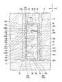
- FIG. 1 corresponds to a cross section taken along line B 1 -B 2 shown in FIG.
- the heat transfer tube 14 shown in FIG. 1 has end portions (one end portion 14A and the other end portion 14B) inserted into first and second through holes 28A and 28B formed in the outer peripheral portion of the tube support plate 13. Has been done.
- end portions one end portion 14A and the other end portion 14B
- the Z direction is one direction in which the outer frame member 31 extends (the height direction of the heat exchanger 10 )
- the X direction is the direction in which the cooling water supply chamber 16 and the cooling water recovery chamber 17 face each other
- Gp is the compressed gas ( Hereinafter, “compressed gas Gp") and Wc represent cooling water (hereinafter, “cooling water Wc”), respectively.
- the Y direction indicates a direction orthogonal to the X direction and the Z direction shown in FIG. 1 to 3, the same components are designated by the same reference numerals.
- the heat exchanger 10 that cools the compressed gas Gp compressed by the compressor that configures the gas turbine with the cooling water Wc that is a fluid will be described below. ..
- the heat exchanger 10 includes a casing 11, a tube support plate 13, a plurality of heat transfer tubes 14, a plate member 15, a cooling water supply chamber 16, a cooling water recovery chamber 17, and a cooling water inlet 22. It has a cooling water outlet 24 and a flow path resistor 25.
- the casing 11 has a casing body 11A, a gas inlet (not shown), and a gas outlet (not shown).
- the casing body 11A has a tubular shape and extends in the Z direction.
- a space 11AB is formed in the casing body 11A.
- the gas inlet (not shown) is provided in the casing body 11A located above the pipe support plate 13.
- the gas inlet introduces the compressed gas Gp into the space 11AB formed above the tube support plate 13.
- the gas outlet (not shown) is provided in the casing body 11A located above the pipe support plate 13.
- the gas outlet (not shown) guides the compressed gas Gp cooled by heat exchange with the cooling water Wc flowing in the plurality of heat transfer tubes 14 from the space 11AB formed above the tube support plate 13.
- the cooled compressed gas Gp is supplied to a place of use (not shown).
- the tube support plate 13 has a support plate body 26, a plurality of first through holes 28A, and a plurality of second through holes 28B.
- the support plate body 26 is a circular plate member.
- the support plate body 26 is arranged at the bottom of the casing body 11A so that a space is formed between the support plate body 26 and the bottom surface of the casing body 11A.
- the support plate body 26 has an upper surface 26a that comes into contact with the compressed gas Gp introduced into the casing body 11A, a lower surface 26b arranged on the opposite side of the upper surface 26a, and a plurality of first through holes 28A. It has a first region 26A and a second region 26B in which a plurality of second through holes 28B are formed.
- the first and second regions 26A, 26B are semicircular in plan view, and are arranged outside the region where the plate member 15 is arranged.
- the first region 26A faces the second region 26B in the X direction.
- the plurality of first through holes 28A are formed by penetrating the support plate body 26 corresponding to the first region 26A in the Z direction. One end 14A of the heat transfer tube 14 is inserted into each of the plurality of first through holes 28A.
- the plurality of second through holes 28B are formed by penetrating the support plate body 26 corresponding to the second region 26B in the Z direction.
- the other end 14B of the heat transfer tube 14 is inserted into each of the plurality of second through holes 28B.
- a plurality of heat transfer tubes 14 are arranged in the space 11AB.
- the plurality of heat transfer tubes 14 have an inverted U shape, and are configured so that the inner diameter and the outer diameter are equal.
- each of the plurality of heat transfer tubes 14 is inserted into each one first through hole 28A among the plurality of first through holes 28A.
- the other ends 14B of the plurality of heat transfer tubes 14 are respectively inserted into one second through hole 28B of the plurality of second through holes 28B. Thereby, the plurality of heat transfer tubes 14 are supported by the tube support plate 13.
- the plurality of heat transfer tubes 14 differ in the distance and height between one end 14A and the other end 14B in the X direction depending on the positions of the first and second through holes 28A and 28B to be inserted. ing. When the compressed gas Gp is introduced into the space 11AB, the outer peripheral surfaces of the plurality of heat transfer tubes 14 come into contact with the compressed gas Gp.
- the plate member 15 includes a lower surface 26b of the support plate body 26 and a bottom surface of the casing body 11A so as to divide the space formed between the support plate body 26 and the bottom surface of the casing body 11A into two in the X direction. It is provided between.
- the plate-shaped member 15 is a member for separating the cooling water supply chamber 16 exposing the plurality of first through holes 28A and the cooling water recovery chamber 17 exposing the plurality of second through holes 28B. ..
- the cooling water supply chamber 16 is partitioned by the bottom surface in the casing body 11A, the pipe support plate 13, and the plate member 15.
- the cooling water supply chamber 16 communicates with the plurality of first through holes 28A.
- the cooling water supply chamber 16 is filled with the cooling water Wc supplied into the one end portion 14A of the plurality of heat transfer tubes 14 via the plurality of first through holes 28A.
- the cooling water Wc in the cooling water supply chamber 16 has a low temperature because it is the cooling water Wc before heat exchange with the compressed gas Gp introduced into the space 11AB.
- the cooling water recovery chamber 17 is partitioned by the bottom surface inside the casing body 11A, the pipe support plate 13, and the plate member 15.
- the cooling water recovery chamber 17 communicates with the plurality of second through holes 28B.
- the cooling water Wc whose temperature has risen by heat exchange with the compressed gas Gp is introduced through the plurality of second through holes 28B.
- the cooling water inlet 22 is provided in a portion of the outside of the bottom portion of the casing body 11A that faces the cooling water supply chamber 16.
- the cooling water inlet 22 projects in a direction away from the casing body 11A.
- the flow path in the cooling water inlet 22 communicates with the cooling water supply chamber 16.
- the cooling water inlet 22 introduces cooling water into the cooling water supply chamber 16. Due to the pressure generated when introducing the cooling water, the cooling water is introduced into the one end portion 14A of the plurality of heat transfer tubes 14 via the cooling water supply chamber 16.
- the pressure of the cooling water Wc introduced into the one end portion 14A of the heat transfer tube 14 tends to be high in the central portion of the tube support plate 13 and lower as it goes toward the outer peripheral portion.
- the cooling water outlet port 24 is provided in a portion of the outside of the bottom portion of the casing body 11A that faces the cooling water recovery chamber 17.
- the cooling water outlet 24 projects in a direction away from the casing body 11A.
- the flow path in the cooling water outlet 24 communicates with the cooling water recovery chamber 17.
- the cooling water outlet port 24 contributes to heat exchange from the cooling water recovery chamber 17 and guides the cooling water Wc whose temperature has risen to the outside of the casing 11.
- the flow path resistor 25 of the first embodiment will be described with reference to FIGS. 1 to 10.
- the same components are designated by the same reference numerals.
- the flow path resistor 25 includes an outer frame member 31, partition plates 32A to 32D (plural partition plates), ribs 33A to 33E, resistance applying portions 34A to 34E (plural resistance applying portions), and a protruding portion 35. And have.
- the outer frame member 31 is a member extending in the Z direction.
- the outer frame member 31 has an outer frame member main body 36, a fluid inlet 38, a fluid outlet 39, and a hollow portion 31A.
- the outer frame member main body 36 includes a cylindrical portion 43 having a cylindrical shape, a circular first plate portion 45 arranged at one end of the cylindrical portion 43, and a circular shape arranged at the other end of the cylindrical portion 43.
- the outer surface 31 a of the outer frame member 31 is configured by the outer peripheral surface 43 a of the tubular portion 43, the outer surface 45 a of the first plate portion 45, and the outer surface 46 a of the second plate portion 46.
- the fluid introducing port 38 is formed on one side of the first plate portion 45 in the X direction so as to penetrate the first plate portion 45.
- the fluid introduction port 38 is an introduction port for introducing the cooling water Wc into the outer frame member 31.
- the fluid introducing port 38 has a size (opening area) that can function as a contracting portion of the resistance applying portion 34A arranged at one end of the outer frame member 31 among the plurality of resistance applying portions 34A to 34E. ing.
- the opening area of the fluid introduction port 38 can be set to be, for example, 50% or less of the opening area inside the heat transfer tube 14.
- the fluid outlet 39 is formed on the other side in the X direction of the second plate portion 46 so as to penetrate the second plate portion 46.
- the fluid outlet 39 passes through the plurality of resistance imparting portions 34A to 34E to guide the cooling water Wc to which the resistance has been imparted into the heat transfer tube 14 located above the flow path resistor 25.
- the fluid lead-out port 39 can function as a contraction section (first contraction section) of the resistance application section 34E arranged at the other end of the outer frame member 31 among the plurality of resistance application sections 34A to 34E. It is the size (opening area).
- the opening area of the fluid outlet 39 can be set to, for example, 50% or less of the opening area inside the heat transfer tube 14.
- the hollow portion 31A is a cylindrical space defined by the inner peripheral surface of the tubular portion 43, the inner surface 45b of the first plate portion 45, and the inner surface 46b of the second plate portion 46.
- the hollow portion 31A connects the fluid inlet 38 and the fluid outlet 39 to each other.
- the dividing plate 32A is a circular plate member, and has a flat surface 32Aa, a flat surface 32Ab arranged on the opposite side of the flat surface 32Aa, and a first contraction portion 32AH.
- the dividing plate 32A is provided on the inner peripheral surface of the outer frame member 31 so that the enlarged diameter portion 51 is defined between the surface 32Aa and the inner surface 45b of the first plate portion 45.
- the expanded diameter portion 51 is a space that is disposed in the hollow portion 31A and serves as a flow path for the cooling water Wc.
- the enlarged diameter portion 51 communicates with the fluid introduction port 38.
- the first contraction portion 32AH is formed so as to penetrate the division plate 32A.
- the first contracted flow portion 32AH communicates with the expanded diameter portion 51, and also communicates with the fluid introduction port 38 via the expanded diameter portion 51.
- the first contraction section 32AH imparts resistance to the cooling water Wc.
- the opening area of the first contraction section 32AH can be set to be, for example, 50% or less of the opening area inside the heat transfer tube 14.
- the first contraction section 32AH is arranged on the other side in the X direction of the division plate 32A. Thereby, in the Z direction, the first contraction section 32AH is formed at a position different from the fluid introduction port 38 functioning as the contraction section.
- the fluid introduction port can be formed without increasing the length of the flow path resistor 25.
- the flow path of the cooling water Wc from 38 to the first contraction section 32AH can be lengthened to give resistance to the cooling water Wc.
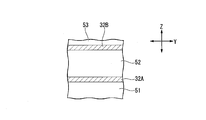
- the dividing plate 32B is a circular plate material, and has a flat surface 32Ba, a surface 32Bb that is a flat surface arranged on the opposite side of the surface 32Ba, and a first contracting portion 32BH.
- the dividing plate 32B is provided on the inner peripheral surface of the outer frame member 31 located above the dividing plate 32A so that the enlarged diameter portion 52 is defined between the surface 32Ba and the surface 32Ab of the dividing plate 32A. ..
- the expanded diameter portion 52 is a space that is disposed in the hollow portion 31A and serves as a flow path for the cooling water Wc.
- the expanded diameter portion 52 communicates with the first contraction portion 32AH.
- the cooling water Wc that has passed through the first contraction section 32AH is introduced into the expanded diameter section 52.
- the first contraction portion 32BH is formed so as to penetrate the dividing plate 32B located on one side in the X direction.
- the first contraction section 32BH communicates with the expanded diameter section 52.
- the first contraction section 32BH is formed at a position different from the first contraction section 32AH.
- the opening area of the first contraction section 32BH can be set to be, for example, 50% or less of the opening area inside the heat transfer tube 14.
- the division plate 32C is a circular plate material, and has a flat surface 32Ca, a surface 32Cb that is a flat surface arranged on the opposite side of the surface 32Ca, and a first constricted portion 32CH.
- the division plate 32C is provided on the inner peripheral surface of the outer frame member 31 located above the division plate 32B so that the enlarged diameter portion 53 is defined between the surface 32Ca and the surface 32Bb of the division plate 32B. ..
- the expanded diameter portion 53 is a space that is disposed in the hollow portion 31A and serves as a flow path for the cooling water Wc.
- the enlarged diameter portion 53 communicates with the first contraction portion 32BH.
- the cooling water Wc that has passed through the first contraction section 32BH is introduced into the enlarged diameter section 53.
- the first contraction section 32CH is formed so as to penetrate the division plate 32C located on the other side in the X direction.
- the first contraction section 32CH communicates with the expanded diameter section 53.
- the first contraction section 32CH is formed at a position different from that of the first contraction section 32BH.
- the opening area of the first contraction portion 32CH can be set to be, for example, 50% or less of the opening area inside the heat transfer tube 14.
- the division plate 32D is a circular plate member, and has a flat surface 32Da, a surface 32Db that is a flat surface arranged on the opposite side of the surface 32Da, and a first contracted flow portion 32DH.
- the partition plate 32D partitions the expanded diameter portion 54 between the surface 32Cb and the surface 32Da of the partition plate 32C, and partitions the expanded diameter portion 55 between the inner surface 46b of the second plate portion 46 and the surface 32Db.
- it is provided on the inner peripheral surface of the outer frame member 31 located above the dividing plate 32C.
- the expanded diameter portions 54 and 55 are spaces that are arranged in the hollow portion 31A and serve as flow paths for the cooling water Wc.
- the enlarged diameter portion 54 communicates with the first contraction portion 32CH.
- the cooling water Wc that has passed through the first contraction section 32CH is introduced into the enlarged diameter section 54.
- the expanded diameter portion 55 communicates with the fluid outlet 39.
- the cooling water Wc that has passed through the expanded diameter portion 55 is led out into the heat transfer tube 14 via the fluid outlet 39.
- the rib 33A is provided on the surface 32Aa so as to divide the surface 32Aa of the dividing plate 32A into two in the X direction.
- the rib 33A extends in the Y direction and projects below the surface 32Aa of the division plate 32A (Z direction). As a result, the rib 33A lowers the height of the central portion of the expanded diameter portion 51.
- the cooling water Wc flowing through the expanded diameter portion 51 can be collided with the rib 33A, and a part of the expanded diameter portion 51 through which the cooling water Wc flows can be narrowed. It becomes possible to do. As a result, the resistance can be further imparted to the cooling water Wc flowing through the expanded diameter portion 51 without increasing the length of the flow path resistor 25.
- the rib 33B is provided on the surface 32Ba so as to divide the surface 32Ba of the dividing plate 32B into two in the X direction.
- the rib 33B extends in the Y direction and projects below the surface 32Ba of the division plate 32B (Z direction).
- the rib 33C is provided on the surface 32Ca so as to divide the surface 32Ca of the dividing plate 32C into two in the X direction.
- the rib 33C extends in the Y direction and projects below the surface 32Ca of the split plate 32C (Z direction).
- the rib 33D is provided on the surface 32Da so as to divide the surface 32Da of the dividing plate 32D into two in the X direction.
- the rib 33D extends in the Y direction and projects below the surface 32Da of the division plate 32D (Z direction).
- the rib 33E is provided on the inner surface 46b so as to divide the inner surface 46b of the second plate portion 46 into two in the X direction.
- the rib 33E extends in the Y direction and projects below the inner surface 46b of the second plate portion 46 (Z direction).
- the ribs 33B to 33D having such a configuration can obtain the same effect as that of the rib 33A described above.
- the resistance applying portions 34A to 34E are arranged inside the outer surface 31a of the outer frame member 31.
- the resistance applying sections 34A to 34E are laminated in the Z direction in the order of the resistance applying section 34A, the resistance applying section 34B, the resistance applying section 34C, the resistance applying section 34D, and the resistance applying section 34E.
- the resistance applying portion 34A has a fluid inlet 38, a first contracting portion 32AH, a diameter expanding portion 51, and a rib 33A.
- the resistance application unit 34A provides resistance to the cooling water Wc when the cooling water Wc passes through the fluid introduction port 38 and the first contraction section 32AH.
- the resistance applying section 34B is arranged between the resistance applying section 34A and the resistance applying section 34C.
- the resistance imparting portion 34B includes a first contracting portion 32BH, an enlarged diameter portion 52 communicating with the first contracting portion 32AH, and a rib 33B.
- the resistance imparting unit 34B configured as described above further imparts resistance to the cooling water Wc to which the resistance has been imparted by the resistance imparting unit 34A.
- the resistance applying section 34C is arranged between the resistance applying section 34B and the resistance applying section 34D.
- the resistance imparting portion 34C includes a first contracting portion 32CH, an enlarged diameter portion 53 that communicates with the first contracting portion 32BH, and a rib 33C.
- the resistance imparting unit 34C configured as described above further imparts resistance to the cooling water Wc to which the resistance has been imparted by the resistance imparting unit 34B.
- the resistance applying section 34D is arranged between the resistance applying section 34C and the resistance applying section 34E.
- the resistance imparting section 34D includes a first contracting section 32DH, an enlarged diameter section 54 communicating with the first contracting section 32CH, and a rib 33D.
- the resistance imparting unit 34D configured as described above further imparts resistance to the cooling water Wc to which the resistance has been imparted by the resistance imparting unit 34C.
- the resistance applying section 34E is arranged on the resistance applying section 34D.
- the resistance imparting section 34E includes a fluid outlet 39 that functions as a first contraction section, an enlarged diameter section 55 that communicates with the first contraction section 32DH, and a rib 33E.
- the resistance imparting unit 34E configured as described above further imparts resistance to the cooling water Wc to which the resistance has been imparted by the resistance imparting unit 34D. Then, the cooling water Wc with sufficient resistance (cooling water Wc having a high pressure) is led out into the heat transfer tube 14 via the fluid outlet 39.
- the protruding portion 35 is provided on the outer peripheral surface 43 a (the outer peripheral surface of the outer frame member 31) located on one end side of the tubular portion 43.
- the protruding portion 35 is a ring-shaped member that protrudes from the outer peripheral surface 43 a to the outside of the outer frame member 31.
- the protrusion 35 is arranged outside the heat transfer tube 14. In this state, the protrusion 35 is in contact with the lower surface 26b of the support plate body 26.
- the one end portion 14A is not attached to the end portion 14A.
- the protrusion 35 can function as a stopper that regulates the position of the flow path resistor 25. Further, since the protrusion 35 can be arranged outside the heat transfer tube 14 in a state where the flow path resistor 25 is arranged inside the one end portion 14A of the heat transfer tube 14, the flow to the heat transfer tube 14 becomes possible. It is possible to easily attach and detach the road resistor 25.
- the resistance applying portions 34A to 34E arranged in the Z direction are provided, and one of the resistance applying portions 34A to 34E adjacent to each other is configured.
- the first contracted flow portion (one of the first contracted flow portions 32AH to 32DH) and the expanded diameter portion (one of the expanded diameter portions 51 to 55) forming the other resistance applying portion are communicated with each other. By doing so, it becomes possible to repeatedly apply resistance to the cooling water Wc. As a result, the cooling water Wc having a high pressure can be led out from the fluid outlet 39, so that the cooling water Wc can be prevented from flowing backward.
- the flow path of the cooling water Wc formed in the outer frame member 31 is formed. It is possible to have a meandering shape. As a result, the flow path of the cooling water Wc can be lengthened, and the cooling water Wc can be made to collide with the inner surface of the outer frame member 31 to further add resistance to the cooling water Wc. Therefore, even when the length of the flow path resistor 25 (the length of the outer frame member 31) is shortened, a large resistance can be imparted to the cooling water Wc, so that the cooling water Wc can be provided in a small occupied area. Backflow can be suppressed.
- the flow path resistor 25 can be manufactured using, for example, a 3D printer. As described above, by using the 3D printer, the flow path resistor 25 having a complicated shape can be easily manufactured.
- the heat exchanger 10 including the flow path resistor 25 configured as described above, it becomes possible to supply the cooling water Wc to which the resistance has been added into the heat transfer tube 14. That is, it becomes possible to supply the cooling water Wc having a high pressure into the heat transfer tube 14. As a result, evaporation of the cooling water Wc due to heat exchange can be suppressed in the heat transfer tube 14, so that the cooling water Wc can be prevented from flowing backward in the heat transfer tube 14. Further, by disposing the flow path resistor 25 in the one end portion 14A of the heat transfer tube 14, it is not necessary to separately secure an installation area of the flow path resistor 25, and therefore, the occupied area of the flow path resistor 25 Can be made smaller.
- the ribs 33A to 33E which extend in the Y direction and divide the area of the surfaces 32Aa to 32Da, 46b into two, are provided as an example.
- a plurality of ribs arranged at intervals in the Y direction may be provided, or the ribs may be provided on a part of the surfaces 32Aa to 32Da, 46b in the Y direction. Even when these ribs are provided, the same effect as that of the ribs 33A to 33E can be obtained.
- the ribs 33A to 33E extending downward are described as an example, but a rib extending upward may be separately provided so as to face the ribs 33A to 33E in the Z direction. Good.
- the Z direction (the direction orthogonal to the dividing plates 32A to 32D) has been described as an example of the direction in which the ribs 33A to 33E project.
- the protruding direction is not limited to the Z direction.
- the direction in which the ribs 33A to 33E project may be any direction that intersects the dividing plates 32A to 32D.
- each heat transfer tube 14 may be provided with a flow path resistor having a resistance applying portion having a different number of stacked layers depending on the pressure of the supplied cooling water Wc.
- each heat transfer tube 14 Variations in the pressure difference of the cooling water Wc flowing inside can be reduced.
- the flow path resistor 60 is different in the formation position of the fluid lead-out port 39 that configures the flow path resistor 25 of the first embodiment, and is a resistance applying portion instead of the resistance applying portion 34E.
- the flow path resistor 25 has the same configuration as that of the flow path resistor 25 except that the flow path resistor 25 is provided.
- the fluid outlet 39 that constitutes the flow path resistor 60 is formed so as to penetrate the central portion of the second plate portion 46.
- the resistance applying portion 61 is configured in the same manner as the resistance applying portion 34E, except that the ribs 62E are provided instead of the ribs 33E.
- the rib 62 is provided on the inner surface 46b of the second plate portion 46 so as to surround the fluid outlet 39. The rib 62 projects in a direction toward the surface 32Db of the division plate 32D.
- the flow path resistor 60 by having the fluid outlet 39 that penetrates the central portion of the second plate portion 46, the collision of the cooling water with the tubular portion 43 can be prevented. Since it can be suppressed, erosion can be suppressed.
- the fluid outlet 39 that penetrates the central portion of the second plate portion 46 the moving direction of the cooling water led out from the fluid outlet 39 can be made the same Z direction as the direction in which the outer frame member 31 extends. It will be possible. Thereby, when the flow path resistor 60 is mounted in the one end portion 14A of the heat transfer tube 14 shown in FIG. 3, the cooling water Wc led out from the fluid lead-out port 39 collides with the inner peripheral surface of the heat transfer tube 14. Can be suppressed.
- the cooling water collides with the rib 62 before reaching the fluid outlet 39. It is possible to add resistance to the cooling water.
- the case where one rib 62 having a ring shape is provided has been described as an example.
- two ribs extending in one direction may be used instead of the rib 62.
- the fluid outlet 39 may be provided between the two ribs. Even when the two ribs configured as described above are provided, the cooling water can be collided with the ribs before reaching the fluid outlet 39, and resistance can be imparted to the cooling water.
- FIGS. 12 and 14 indicate the moving direction of the cooling water.
- the flow path resistor 65 has a plurality of partitions in which a second contraction portion 66A is formed in place of the ribs 33A to 33E and the resistance applying portions 34A to 34E which form the flow path resistor 25 of the first embodiment.
- the flow path resistor 25 has the same configuration except that it has the plate 66 and the resistance applying portions 69A to 69E.
- the partition plate 66 is divided between the first plate portion 45 and the division plate 32A, between the division plate 32A and the division plate 32B, and between the division plate 32B so as to divide each of the expanded diameter portions 51 to 55 into two. It is provided between the division plate 32C, between the division plate 32C and the division plate 32D, and between the division plate 32E and the second plate portion 46, respectively.
- the second contraction portion 66A is formed so as to penetrate the central portion of the partition plate 66.
- the inner diameter of the second contraction section 66A can be set within the same range as the inner diameters of the first contraction sections 32AH to 32DH, for example.
- the resistance applying portions 69A to 69E are arranged inside the outer surface 31a of the outer frame member 31.
- the resistance applying portions 69A to 69E are laminated in the Z direction in the order of the resistance applying portion 69A, the resistance applying portion 69B, the resistance applying portion 69C, the resistance applying portion 69D, and the resistance applying portion 69E.
- the resistance applying portion 69A is configured in the same manner as the resistance applying portion 34A, except that the resistance applying portion 69A has a partition plate 66 in which a second contracted portion 66A is formed instead of the rib 33A that constitutes the resistance applying portion 34A. ..
- the resistance applying portion 69B is configured in the same manner as the resistance applying portion 34B, except that it has a partition plate 66 in which a second contracting portion 66A is formed instead of the rib 33B that constitutes the resistance applying portion 34B. ..
- the resistance applying portion 69C is configured in the same manner as the resistance applying portion 34C, except that the resistance applying portion 34C includes a partition plate 66 in which a second contraction portion 66A is formed instead of the rib 33C configuring the resistance applying portion 34C. ..
- the resistance applying section 69D is configured in the same manner as the resistance applying section 34D, except that the resistance applying section 69D has a partition plate 66 formed with a second contracting section 66A instead of the rib 33D forming the resistance applying section 34D. ..
- the resistance applying portion 69E is configured in the same manner as the resistance applying portion 34E, except that the resistance applying portion 69E has a partition plate 66 in which a second contracted portion 66A is formed instead of the rib 33E that configures the resistance applying portion 34E. ..
- each of the expanded diameter portions 51 to 55 is divided into two, and a plurality of partition plates 66 having the second contraction portion 66A are provided to cool the flow passage resistor 65. It becomes possible to give resistance to the cooling water when the water passes through the second contraction section 66A. As a result, the length of the flow path resistor 65 can be further shortened, so that the backflow of the cooling water can be suppressed in a smaller occupied area.
- FIGS. 15 to 21 A flow path resistor 75 according to a third embodiment of the present invention will be described with reference to FIGS. 15 to 21.
- 15 to 21 the same components as those of the structures shown in FIGS. 4 to 9 are designated by the same reference numerals. Further, in FIGS. 15 to 21, the same components are designated by the same reference numerals. Furthermore, the arrows shown in FIGS. 16 to 20 indicate the moving direction of the cooling water.
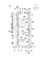
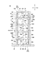
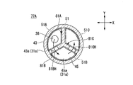
- the flow path resistor 75 is divided into partition plates 81A to 81C, 82A to 82C and 83A in place of the plurality of partition plates 66 and the resistance applying portions 34A to 34E which form the flow path resistor 65 of the second embodiment. It is configured in the same manner as the flow path resistor 65 except that it has 83C, 84A to 84C, 85A to 85C, and resistance applying portions 77A to 77E.
- the partition plates 81A to 81C are provided between the first plate portion 45 and the split plate 32A so as to divide the expanded diameter portion 51 into the first to third portions 51A to 51C.
- the first portion 51A is partitioned by a partition plate 81A and a partition plate 81B.
- the second portion 51B is partitioned by a partition plate 81B and a partition plate 81C.
- the third portion 51C is partitioned by a partition plate 81C and a partition plate 81A.
- the cooling water introduced from the fluid inlet 38 flows into the first portion 51A.
- the partition plate 81B has a second contraction portion 81BH formed in the central portion.
- the second contraction portion 81BH connects the first portion 51A and the second portion 51B.
- the cooling water that has flowed into the first portion 51A flows into the second portion 51B via the second contraction portion 81BH.
- the partition plate 81C has a second contraction portion 81CH formed in the central portion.
- the second contraction section 81CH connects the second portion 51B and the third portion 51C.
- the cooling water that has flowed into the second portion 51B flows into the third portion 51C.
- the partition plate 81A does not have a contracting portion. Therefore, the cooling water that has flowed into the third portion 51C does not flow into the first portion 51A.
- the partition plates 82A to 82C are provided between the dividing plates 32A and 32B so as to divide the expanded diameter portion 52 into the first to third portions 52A to 52C.
- the first portion 52A is partitioned by the partition plate 82A and the partition plate 82B, and is arranged above the third portion 51C.
- the second portion 52B is partitioned by the partition plate 82B and the partition plate 82C, and is arranged above the first portion 51A.
- the third portion 52C is partitioned by the partition plate 82C and the partition plate 82A, and is arranged above the second portion 51B.
- the cooling water that has passed through the third portion 51C flows into the first portion 52A.
- the partition plate 82B has a second contraction portion 82BH formed in the central portion.
- the second contraction portion 82BH connects the first portion 52A and the second portion 52B.
- the cooling water that has flowed into the first portion 52A flows into the second portion 52B via the second contraction portion 82BH.
- the partition plate 82C has a second contraction portion 82CH formed in the central portion.
- the second contraction section 82CH connects the second portion 52B and the third portion 52C.
- the cooling water that has flowed into the second portion 52B flows into the third portion 52C via the second contraction portion 82CH.
- the partition plate 82A does not have a contracting portion. Therefore, the cooling water that has flowed into the third portion 52C does not flow into the first portion 52A.
- the partition plates 83A to 83C are provided between the dividing plates 32B and 32C so as to divide the expanded diameter portion 53 into the first to third portions 53A to 53C.
- the first portion 53A is partitioned by the partition plate 83A and the partition plate 83B, and is arranged above the third portion 52C.
- the second portion 53B is partitioned by the partition plate 83B and the partition plate 83C, and is arranged above the first portion 52A.
- the third portion 53C is partitioned by the partition plate 83C and the partition plate 83A, and is arranged above the second portion 52B.
- the cooling water that has passed through the third portion 51C flows into the first portion 53A.
- the partition plate 83B has a second contraction portion 83BH formed in the central portion.
- the second contraction portion 83BH connects the first portion 53A and the second portion 53B.
- the cooling water that has flown into the first portion 53A flows into the second portion 53B via the second contraction portion 83BH.
- the partition plate 83C has a second contraction portion 83CH formed in the central portion.
- the second contraction portion 83CH connects the second portion 53B and the third portion 53C.
- the cooling water that has flowed into the second portion 53B flows into the third portion 53C via the second contraction portion 83CH.
- the partition plate 83A does not have a contracting portion. Therefore, the cooling water that has flowed into the third portion 53C does not flow into the first portion 53A.
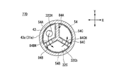
- the partition plates 84A to 84C are provided between the dividing plates 32B and 32C so as to divide the expanded diameter portion 54 into the first to third portions 54A to 54C.
- the first portion 54A is partitioned by the partition plate 84A and the partition plate 84B, and is arranged above the third portion 53C.
- the second portion 54B is partitioned by the partition plate 84B and the partition plate 84C, and is arranged above the first portion 53A.
- the third portion 54C is partitioned by the partition plate 84C and the partition plate 84A, and is arranged above the second portion 53B.
- the cooling water that has passed through the third portion 52C flows into the first portion 54A.
- the partition plate 84B has a second contraction portion 84BH formed in the central portion.
- the second contraction portion 84BH communicates the first portion 54A and the second portion 54B.
- the cooling water that has flown into the first portion 54A flows into the second portion 54B via the second contraction portion 84BH.
- the partition plate 84C has a second contraction portion 84CH formed in the central portion.
- the second contraction portion 84CH communicates the second portion 54B and the third portion 54C.
- the cooling water that has flowed into the second portion 54B flows into the third portion 54C via the second contraction portion 84CH.
- the partition plate 84A does not have a contracting portion. Therefore, the cooling water that has flowed into the third portion 54C does not flow into the first portion 54A.
- the partition plates 85A to 85C are provided between the dividing plates 32B and 32C so as to divide the expanded diameter portion 55 into the first to third portions 55A to 55C.
- the first portion 55A is partitioned by a partition plate 85A and a partition plate 85B, and is arranged above the third portion 54C.
- the second portion 55B is partitioned by a partition plate 85B and a partition plate 85C, and is arranged above the first portion 54A.
- the third portion 55C is partitioned by the partition plate 85C and the partition plate 85A, and is arranged above the second portion 54B.
- the partition plate 85B has a second contraction portion 85BH formed in the central portion.
- the second contraction portion 85BH connects the first portion 55A and the second portion 55B.
- the cooling water that has flown into the first portion 55A flows into the second portion 55B via the second contraction portion 85BH.
- the partition plate 85C has a second contraction portion 85CH formed in the central portion.
- the second contraction section 85CH connects the second portion 55B and the third portion 55C.
- the cooling water that has flowed into the second portion 55B flows into the third portion 55C via the second contraction portion 85CH.
- the cooling water that has passed through the third portion 53C is led out from the fluid outlet 39.
- the partition plate 85A does not have a contracting portion. Therefore, the cooling water that has flowed into the third portion 55C does not flow into the first portion 55A.
- the resistance applying portions 77A to 77E are arranged inside the outer surface 31a of the outer frame member 31.
- the resistance applying portions 77A to 77E are laminated in the Z direction in the order of the resistance applying portion 77A, the resistance applying portion 77B, the resistance applying portion 77C, the resistance applying portion 77D, and the resistance applying portion 77E.
- the resistance applying portion 77A is configured in the same manner as the resistance applying portion 34A, except that it has partition plates 81A to 81C instead of the rib 33A that constitutes the resistance applying portion 34A described in the first embodiment.
- the resistance imparting portion 77A includes a diameter-enlarged portion 51 that is divided into first to third portions 51A to 51C, a fluid inlet 38 that functions as a first contraction portion, and a first contraction portion 32AH. It has 2nd contraction parts 81BH and 81CH.
- the resistance applying portion 77B is configured in the same manner as the resistance applying portion 34B, except that it has partition plates 82A to 82C instead of the ribs 33B forming the resistance applying portion 34B described in the first embodiment.
- the resistance imparting portion 77B has a diameter expanding portion 52 divided into first to third portions 52A to 52C, a first contracting portion 32BH, and second contracting portions 82BH and 82CH.
- the resistance applying portion 77C is configured in the same manner as the resistance applying portion 34C, except that it has partition plates 83A to 83C instead of the ribs 33C configuring the resistance applying portion 34C described in the first embodiment.
- the resistance imparting portion 77C has a diameter expanding portion 53 divided into first to third portions 53A to 53C, a first contracting portion 32CH, and second contracting portions 83BH and 83CH.
- the resistance applying portion 77D is configured in the same manner as the resistance applying portion 34D, except that it has partition plates 84A to 84C instead of the rib 33D configuring the resistance applying portion 34D described in the first embodiment.
- the resistance imparting portion 77D has a diameter-increasing portion 54 divided into first to third portions 54A to 54C, a first contracting portion 32DH, and second contracting portions 84BH and 84CH.
- the resistance applying portion 77E is configured in the same manner as the resistance applying portion 34E, except that it has partition plates 85A to 85C instead of the ribs 33E forming the resistance applying portion 34D described in the first embodiment.
- the resistance imparting portion 77E includes the enlarged diameter portion 55 divided into the first to third portions 55A to 55C, the fluid outlet port 39 functioning as the first contraction portion, and the second contraction portions 85BH and 85CH. And have.
- the partition plates 81A to 81C, 82A to 82C, 83A to 83C, 84A to 84C, 85A to 85C that divide the expanded diameter portions 51 to 55 into three parts are provided.
- the cooling water will pass through the second constriction parts 81BH, 81CH, 82BH, 82CH, 82BH, 83CH, 84BH, 84CH, 85BH, 85CH. Can be suppressed.
- each of the expanded diameter portions 51 to 55 is divided into three has been described, but a partition plate having a second contraction portion is further provided.
- the expanded diameter portions 51 to 55 may be divided into four or more.
- FIGS. 22 to 25 A flow path resistor 90 according to the fourth exemplary embodiment of the present invention will be described with reference to FIGS. 22 to 25, the same components as those of the structure shown in FIG. 4 are designated by the same reference numerals. 22 to 25, the same components are designated by the same reference numerals. 23 to 25, for convenience of description, the illustration of the outer frame member 31 shown in FIG. 22 is omitted. The arrows shown in FIGS. 23 to 25 indicate the moving directions of the cooling water.
- the flow path resistor 90 has resistance applying portions 91A to 91E in place of the resistance applying portions 34A to 34E forming the flow path resistor 25 of the first embodiment, and is further housed in the outer frame member 31, Except that the plate members 93 to 97 are arranged at intervals in the circumferential direction of the outer frame member 31, and the shapes and positions of the fluid inlet port 38 and the fluid outlet port 39 are different from those of the flow path resistor 25. Is configured similarly to the flow path resistor 25.
- the resistance applying portions 91A to 91E each have a shape extending in the Z direction.
- the resistance applying portions 91A to 91E are arranged in the circumferential direction of the outer frame member 31 in the order of the resistance applying portion 91A, the resistance applying portion 91B, the resistance applying portion 91C, the resistance applying portion 91D, and the resistance applying portion 91E.
- the resistance imparting portion 91A has an enlarged diameter portion 92A and first to third partition plates 101 to 103.
- the expanded diameter portion 92A is partitioned by the plate members 93 and 94 and the first and second plate portions 45 and 46, and extends in the Z direction.
- the first partition plate 101 is a fan-shaped plate material.
- the first partition plate 101 is arranged above the fan-shaped fluid introduction port 38 and in the lower portion inside the outer frame member 31.
- the first partition plate 101 is fixed to the plate members 93 and 94.
- the 1st partition plate 101 has the 1st contraction
- the cooling water introduced from the fluid introduction port 38 is introduced into the expanded diameter portion 92A.
- the second partition plate 102 is a fan-shaped plate material.
- the second partition plate 102 is disposed below the second plate portion 46 and above the outer frame member 31.
- the second partition plate 102 is fixed to the plate members 94 and 95.
- the second partition plate 102 has a first contraction portion 102A formed so as to penetrate through the central portion.
- the third partition plate 103 is a fan-shaped plate material.
- the third partition plate 103 is arranged in the middle part of the outer frame member 31 located above the first partition plate 101 and below the second partition plate 102.
- the third partition plate 103 is fixed to the plate members 95 and 96.
- the third partition plate 103 has a first contraction portion 103A formed so as to penetrate the central portion.
- the cooling water that has passed through the first contraction portion 103A flows into the expanded diameter portion 92A located between the first partition plate 101 and the third partition plate 103.
- the cooling water that has flowed into the expanded diameter portion 92A has a first reduced flow portion 103A, an enlarged diameter portion 92A located between the first partition plate 101 and the third partition plate 103, and a first reduced flow portion. After sequentially passing through 102A, it flows to the upper end portion of the resistance applying portion 91B.
- the resistance imparting portion 91B includes an enlarged diameter portion 92B having a shape similar to that of the enlarged diameter portion 92A, and first to third partition plates 101 to 103.
- the expanded diameter portion 92B is partitioned by the plate members 94 and 95 and the first and second plate portions 45 and 46.
- the cooling water flowing in the resistance imparting section 91A passes through the first contracting section 102A, the first contracting section 103A, and the first contracting section 101A arranged in the enlarged diameter section 92B in this order. .. After that, the cooling water flows to the lower end portion of the resistance applying portion 91C.
- the resistance applying portion 91C has an enlarged diameter portion 92C having the same shape as the enlarged diameter portion 92A, and first to third partition plates 101 to 103.
- the expanded diameter portion 92C is partitioned by the plate materials 95 and 96 and the first and second plate portions 45 and 46.
- the cooling water flowing in the resistance imparting section 91B passes through the first contracting section 101A, the first contracting section 103A, and the first contracting section 102A arranged in the enlarged diameter section 92C in this order. .. After that, the cooling water flows to the upper end portion of the resistance applying portion 91D.
- the resistance imparting portion 91D has an enlarged diameter portion 92D having a shape similar to that of the enlarged diameter portion 92A, and first to third partition plates 101 to 103.
- the expanded diameter portion 92D is partitioned by the plate members 96 and 97 and the first and second plate portions 45 and 46.
- the cooling water that has passed through the resistance imparting section 91C passes through the first contracting section 102A, the first contracting section 103A, and the first contracting section 101A, which are arranged in the expanded diameter section 92D, in this order. After that, the cooling water flows to the lower end portion of the resistance applying portion 91E.
- the resistance imparting portion 91E includes an enlarged diameter portion 92E having a shape similar to that of the enlarged diameter portion 92A, and first to third partition plates 101 to 103.
- the expanded diameter portion 92E is partitioned by the plate members 97 and 93 and the first and second plate portions 45 and 46.
- the cooling water that has passed through the resistance imparting section 91D passes through the first contraction section 101A, the first contraction section 103A, and the first contraction section 102A arranged in the diameter expansion section 92E in this order. Then, the cooling water is led out from the fluid outlet 39.
- the plate member 93 is arranged between the expanded diameter portion 92A and the expanded diameter portion 92E.
- the plate member 93 extends in the Z direction and has one end connected to the inner surface of the first plate portion 45 and the other end connected to the inner surface of the second plate portion 46.
- the plate member 94 is arranged between the expanded diameter portion 92A and the expanded diameter portion 92B.
- the plate member 94 extends in the Z direction.
- One end of the plate member 94 is connected to the inner surface of the first plate portion 45.
- the other end of the plate member 94 is connected to the second partition plate 102 forming the resistance applying portion 91A and the second partition plate 102 forming the resistance applying portion 91B so as not to project above the second partition plate 102.
- the plate member 95 is arranged between the expanded diameter portion 92B and the expanded diameter portion 92C.
- the plate member 95 extends in the Z direction.
- One end of the plate member 95 is connected to the first partition plate 101 forming the resistance applying portion 91B and the first partition plate 101 forming the resistance applying portion 91C so as not to project below the first partition plate 101. ing.
- the other end of the plate member 95 is connected to the inner surface of the second plate portion 46.
- the plate member 96 is arranged between the expanded diameter portion 92C and the expanded diameter portion 92D.
- the plate material 96 extends in the Z direction.
- One end of the plate material 96 is connected to the inner surface of the first plate portion 45.
- the other end of the plate member 96 is connected to the second partition plate 102 which constitutes the resistance applying section 912C and the second partition plate 102 which constitutes the resistance applying section 91D so as not to project above the second partition plate 102.
- the plate member 96 having such a configuration, the cooling water derived from the resistance applying portion 91C can be introduced into the resistance applying portion 91D.
- the plate member 97 is arranged between the expanded diameter portion 92D and the expanded diameter portion 92E.
- the plate member 97 extends in the Z direction.
- One end of the plate member 97 is connected to the first partition plate 101 forming the resistance applying portion 91D and the first partition plate 101 forming the resistance applying portion 91E so as not to project below the first partition plate 101. ing.
- the other end of the plate member 97 is connected to the inner surface of the second plate portion 46.
- the flow path resistor 90 has the above-described first to third partition plates 101 to 103 and the expanded diameter portions 92A to 92E, and is arranged in the circumferential direction of the outer frame member 31.
- the resistance imparting portions 91A to 91E arranged, the cooling water flowing through the resistance imparting portions 91A to 91E can be connected to the resistance imparting portions after passing through the first contraction portion 101A or the first contraction portion 102A. It becomes possible to flow in another adjacent resistance applying portion. Therefore, the length of the flow path resistor 90 can be shortened, and then the flow path of the cooling water can be lengthened to repeatedly apply resistance to the cooling water.
- the case where five resistance applying portions (resistance applying portions 91A to 91E) are arranged in the circumferential direction of the outer frame member 31 has been described as an example, but the outer frame member is described.
- the number of the resistance applying portions 31 arranged in the circumferential direction can be set as appropriate and is not limited to five.
- the case where one third partition plate 103 is provided has been described as an example, but the number of the third partition plates 103 may be one or more. It is not limited to one.
- FIGS. 26 and 27 The flow path resistor 110 according to the fifth exemplary embodiment of the present invention will be described with reference to FIGS. 26 and 27.
- 26 and 27 the same components as those of the structure shown in FIG. 4 are designated by the same reference numerals. 26 and 27, the same components are designated by the same reference numerals.
- the arrow shown in FIG. 26 indicates the moving direction of the cooling water.
- the flow path resistor 110 of the fifth embodiment is different from the flow path resistor 25 of the first embodiment in that it includes the dividing plates 32A to 32D, the ribs 33A to 33E, and the resistance applying portions 34A to 34E. It has the same configuration as the flow path resistor 25 except that it has the first inclined plate 111, 113, 115, 117, the second inclined plate 112, 114, 116, the expanded diameter portions 121 to 128, and the rib 129. There is.
- the first inclined plates 111, 113, 115, 117 are housed in the outer frame member 31.
- the first tilted plates 111, 113, 115, 117 are arranged such that the first tilted plate 111, the first tilted plate 113, the first tilted plate 111, the first tilted plate 111
- the inclined plate 115 and the first inclined plate 117 are arranged in this order at intervals.
- the first inclined plates 111, 113, 115, 117 are inclined at the same angle with respect to the Z direction.
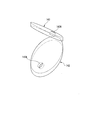
- the first inclined plate 111 is an elliptical plate material.
- the first inclined plates 113, 115, 117 have a shape in which a part of an elliptical plate material is linearly cut out.
- Each of the first inclined plates 111, 113, 115, 117 has a curved portion 132.
- Each curved portion 132 is connected to the inner peripheral surface 36a of the outer frame member main body 36.
- the first inclined plates 113, 115, 117 have a linear portion 133.
- the 1st inclination board 111 has the 1st contraction
- the first inclined plate 113 has a first contraction portion 113A which is formed so as to penetrate a part thereof and through which cooling water passes.
- the first inclined plate 115 has a first contracted flow portion 115A formed so as to penetrate a part thereof and through which cooling water passes.
- the first inclined plate 117 has a first contraction portion 117A which is formed so as to penetrate a part thereof and through which cooling water passes.
- the second inclined plates 112, 114, 116 are housed in the outer frame member 31.
- the second inclined plates 112, 114, and 116 are the second inclined plate 112, the second inclined plate 114, and the second inclined plate with respect to the direction from the first plate portion 45 toward the second plate portion 46.
- the plates 116 are arranged at intervals in this order.
- the second inclined plates 112, 114, 116 are inclined in a direction (an example of a different direction) opposite to the direction in which the first inclined plates 111, 113, 115, 117 are inclined.
- the second inclined plates 112, 114, 116 are inclined at the same angle with respect to the Z direction.
- the second inclined plates 112, 114, and 116 have a shape in which a part of an elliptical plate material is linearly cut out.
- the second inclined plates 112, 114, 116 have a curved portion 135 and a linear portion 136. Each curved portion 132 is connected to the inner peripheral surface 36a of the outer frame member main body 36.
- the second inclined plate 112 has a second contraction portion 112A which is formed so as to penetrate a part thereof and through which cooling water which is a fluid passes.
- the second inclined plate 112 is arranged above the first inclined plate 111.
- the linear portion 136 of the second inclined plate 112 is connected to the upper surface 111a of the first inclined plate 111.
- the straight portion 133 of the first inclined plate 113 is connected to the surface of the upper surface 112a of the second inclined plate 112 that is located above the second contraction portion 112A.
- the second inclined plate 114 has a second contraction portion 114A which is formed so as to penetrate a part thereof and through which cooling water which is a fluid passes.
- the second inclined plate 114 is arranged above the first inclined plate 113.
- the linear portion 136 of the second inclined plate 114 is connected to the upper surface 113a of the first inclined plate 113.
- the straight portion 133 of the first inclined plate 115 is connected to the surface of the upper surface 114a of the second inclined plate 114 that is located above the second contraction portion 114A.
- the second inclined plate 116 has a second contraction portion 116A which is formed so as to penetrate a part thereof and through which cooling water which is a fluid passes.
- the second inclined plate 116 is arranged above the first inclined plate 115.
- the straight portion 136 of the second inclined plate 116 is connected to the upper surface 115a of the first inclined plate 115.
- the straight portion 133 of the first inclined plate 117 is connected to a surface of the upper surface 116a of the second inclined plate 116 that is located above the second contraction portion 116A.
- the second contraction sections 112A, 114A, 116A may be formed at positions different from the first contraction sections 111A, 113A, 115A, 117A in a plan view from the fluid outlet 39 side. By forming the second contraction portions 112A, 114A, and 116A at such positions, it is possible to increase the length of the flow path through which the cooling water passes, so that a large resistance is imparted to the cooling water. be able to.
- the opening area of the first contracting portions 111A, 113A, 115A, 117A and the second contracting portions 112A, 114A, 116A can be, for example, half or less of the opening area of the outer frame member main body 36. ..
- the expanded diameter portion 121 is arranged below the first inclined plate 111.
- the enlarged diameter portion 121 is defined by the first inclined plate 111, the first plate portion 45, and the inner peripheral surface 36 a of the outer frame member body 36 located below the first inclined plate 111.
- the enlarged diameter portion 121 communicates with the fluid introduction port 38 and the first contraction portion 111A. That is, the cooling water that has flowed in from the fluid introduction port 38 passes through the diameter expansion portion 121 and the first contraction portion 111A in this order.
- the enlarged diameter portion 122 is arranged above the first inclined plate 111 and below the second inclined plate 112.
- the enlarged diameter portion 122 includes the first inclined plate 111, the second inclined plate 112, and the outer frame member main body 36 located above the first inclined plate 111 and below the second inclined plate 112. It is partitioned by the inner peripheral surface 36a.
- the expanded diameter portion 122 communicates with the first contraction section 111A and the second contraction section 112A.
- the cooling water that has flowed into the enlarged diameter portion 122 via the first reduced flow portion 111A is led out from the enlarged diameter portion 122 via the second reduced flow portion 112A.
- the enlarged diameter portion 123 is arranged above the first inclined plate 111 and below the first inclined plate 113.
- the enlarged diameter portion 122 is located on the first inclined plates 111, 113, the second inclined plate 112, and the first inclined plate 111, and is located below the first inclined plate 113. It is partitioned by the inner peripheral surface 36 a of the main body 36.
- the expanded diameter portion 123 communicates with the second contraction portion 112A and the first contraction portion 113A.
- the cooling water that has flowed into the expanded diameter portion 123 via the second contracted portion 112A is discharged from the expanded diameter portion 123 via the first contracted portion 113A.
- the enlarged diameter portion 124 is arranged above the second inclined plate 112 and below the second inclined plate 114.
- the enlarged diameter portion 124 is an outer frame member located above the first inclined plate 113, the second inclined plates 112 and 114, and the second inclined plate 112, and below the second inclined plate 114. It is partitioned by the inner peripheral surface 36 a of the main body 36.
- the enlarged diameter portion 124 communicates with the first contraction portion 113A and the second contraction portion 114A.
- the cooling water that has flowed into the enlarged diameter portion 124 via the first reduced flow portion 113A is led out from the enlarged diameter portion 124 via the second reduced flow portion 114A.
- the enlarged diameter portion 125 is arranged above the first inclined plate 113 and below the first inclined plate 115.
- the enlarged diameter portion 125 includes the first inclined plates 113 and 115, the second inclined plate 114, and an outer frame member located above the first inclined plate 113 and below the first inclined plate 115. It is partitioned by the inner peripheral surface 36 a of the main body 36.
- the expanded diameter portion 125 communicates with the second contraction portion 114A and the first contraction portion 115A.
- the cooling water that has flowed into the expanded diameter portion 125 via the second contracted portion 114A is led out from the expanded diameter portion 125 via the first contracted portion 115A.
- the enlarged diameter portion 126 is arranged above the second inclined plate 114 and below the second inclined plate 115.
- the enlarged diameter portion 125 is an outer frame member that is located above the first inclined plate 115, the second inclined plates 114 and 116, and the second inclined plate 114, and below the second inclined plate 116. It is partitioned by the inner peripheral surface 36 a of the main body 36.
- the enlarged diameter portion 126 communicates with the first contraction portion 115A and the second contraction portion 116A.
- the cooling water that has flowed into the expanded diameter portion 125 via the first contracted flow portion 115A is led out from the expanded diameter portion 126 via the second contracted flow portion 116A.
- the expanded diameter portion 127 is arranged above the first inclined plate 115 and below the first inclined plate 117.
- the enlarged diameter portion 127 is an outer frame member located above the first inclined plates 115 and 117, the second inclined plate 116, and the first inclined plate 115, and below the first inclined plate 117. It is partitioned by the inner peripheral surface 36 a of the main body 36.
- the enlarged diameter portion 127 communicates with the second contraction portion 116A and the first contraction portion 117A.
- the cooling water that has flowed into the expanded diameter portion 127 through the second contracted portion 116A is led out from the expanded diameter portion 127 through the first contracted portion 117A.
- the enlarged diameter portion 128 is arranged above the first inclined plate 117 and the second inclined plate 116.
- the enlarged diameter portion 128 includes a first inclined plate 117, a second inclined plate 116, a second plate portion 46, and an outer frame member located between the second plate portion 46 and the first inclined plate 127. It is partitioned by the inner peripheral surface 36 a of the main body 36.
- the enlarged diameter portion 128 communicates with the first contraction portion 117A and the fluid outlet 39.
- the cooling water that has flowed into the enlarged diameter portion 128 via the first contraction portion 117A is led out from the enlarged diameter portion 128 via the fluid outlet 39.
- the rib 129 is provided on the upper surface 117 a of the first inclined plate 117 located near the fluid outlet 39. By providing such ribs 129, it is possible to narrow the flow passage width of the enlarged diameter portion 128 located on the fluid outlet port 39 side, so that resistance is imparted to the cooling water toward the fluid outlet port 39. can do.
- the flow path resistor 110 is manufactured using the 3D printer by having the first inclined plates 111, 113, 115, 117 and the second inclined plates 112, 114, 116 which are inclined with respect to the Z direction. In this case, the strength of the first inclined plates 111, 113, 115, 117 and the second inclined plates 112, 114, 116 can be improved.
- the fluid outlet 39 is formed at a position deviated from the central portion of the second plate portion 46 is described, but for example, the second plate portion is used.
- the fluid outlet 39 may be formed in the central portion of 46.
- the first inclined plates 111, 113, 115, 117 are inclined at the same angle
- the first inclined plates 111, 113, The inclination angles of 115 and 117 may be different from each other.
- the case where the second inclined plates 112, 114, and 116 are inclined at the same angle has been described as an example, but the second inclined plates 112, 114, and 116 are not included.
- the inclination angles may be different.
- ribs may be provided on the first inclined plates 111, 113, 115 and the second inclined plates 112, 114, 116.
- FIGS. 28 and 29 With reference to FIGS. 28 and 29, a flow path resistor 140 according to the sixth embodiment of the present invention will be described. 28 and 29, the same components as those of the structure shown in FIG. 4 are designated by the same reference numerals. 28 and 29, the same components are designated by the same reference numerals. The arrow shown in FIG. 28 indicates the moving direction of the cooling water.
- the flow path resistor 140 of the sixth embodiment is different from the split plates 32A to 32D, the ribs 33A to 33E, and the resistance applying portions 34A to 34E, which form the flow path resistor 25 of the first embodiment, in that
- the configuration is the same as that of the flow path resistor 25 except that the first inclined plates 141 and 143, the second inclined plate 142, and the expanded diameter portions 145 to 148 are provided.
- the first inclined plates 141 and 143 are housed in the outer frame member 31.
- the first inclined plates 141 and 143 are spaced from each other in the order of the first inclined plate 141 and the first inclined plate 143 in the direction from the first plate portion 45 toward the second plate portion 46. It is arranged.
- the first inclined plates 141 and 143 are inclined at the same angle with respect to the Z direction.
- the first inclined plates 141 and 143 are plate materials having an elliptical shape.
- the outer peripheral surfaces of the first inclined plates 141 and 143 are connected to the inner peripheral surface 36 a of the outer frame member main body 36.
- the first inclined plate 141 has a first contraction portion 141A which is formed so as to penetrate a part thereof and through which cooling water as a fluid passes.
- the first inclined plate 143 has a first contraction portion 143A which is formed so as to penetrate a part thereof and through which cooling water passes.
- the second inclined plate 142 is housed in the outer frame member 31.
- the second inclined plate 142 is arranged between the first inclined plate 141 and the first inclined plate 143.
- the second inclined plate 142 is inclined in a direction opposite to the direction in which the first inclined plates 141 and 143 are inclined.
- the second inclined plate 142 has a shape in which a part of an elliptical plate material is linearly cut out.
- the second inclined plates 112, 114, 116 have a curved portion 135 and a linear portion 136. Each curved portion 132 is connected to the inner peripheral surface 36a of the outer frame member main body 36.
- the second inclined plate 142 has a second contraction portion 142A which is formed so as to penetrate a part thereof and through which cooling water which is a fluid passes.
- the second inclined plate 142 is arranged between the first inclined plate 141 and the first inclined plate 143.
- the second contraction portion 142A may be formed at a position different from the positions of the first contraction portions 141A and 143A in a plan view from the fluid outlet 39 side. By forming the second contraction portion 142A at such a position, it is possible to increase the length of the flow path through which the cooling water passes, so that a large resistance can be imparted to the cooling water.
- the opening areas of the first contracting portions 141A, 143A and the second contracting portion 142A can be, for example, half or less of the opening area of the outer frame member main body 36.
- the enlarged diameter portion 145 is arranged below the first inclined plate 141.
- the enlarged diameter portion 145 is defined by the first inclined plate 141, the first plate portion 45, and the inner peripheral surface 36 a of the outer frame member main body 36 located below the first inclined plate 141.
- the enlarged diameter portion 145 communicates with the fluid inlet 38 and the first contraction portion 141A. That is, the cooling water flowing in from the fluid introduction port 38 passes through the expanded diameter portion 145 and the first contraction portion 141A in this order.
- the enlarged diameter portion 146 is arranged between the first inclined plate 141 and the second inclined plate 142.
- the enlarged diameter portion 146 is located on the first inclined plate 141, the second inclined plate 142, and above the first inclined plate 141, and below the second inclined plate 142. It is partitioned by the inner peripheral surface 36a.
- the enlarged diameter portion 146 communicates with the first contraction portion 141A and the second contraction portion 142A.
- the cooling water that has flowed into the expanded diameter portion 146 via the first reduced flow portion 141A is led out from the expanded diameter portion 146 via the second reduced flow portion 142A.
- the expanded diameter portion 147 is arranged between the second inclined plate 142 and the first inclined plate 143.
- the enlarged diameter portion 147 includes the first inclined plate 143, the second inclined plate 142, and the inner peripheral surface 36a of the outer frame member main body 36 located between the first inclined plate 143 and the second inclined plate 142. It is divided by.
- the expanded diameter portion 147 communicates with the second contraction portion 142A and the first contraction portion 143A.
- the cooling water that has flowed into the expanded diameter portion 143 via the second contracted portion 142A is led out from the expanded diameter portion 147 via the first contracted portion 143A.
- the expanded diameter portion 148 is arranged between the first inclined plate 143 and the second plate portion 46.
- the enlarged diameter portion 148 is located above the first inclined plate 143, the second plate portion 46, and the first inclined plate 143, and below the second plate portion 46. It is partitioned by the inner peripheral surface 36a.
- the enlarged diameter portion 148 communicates with the first contraction portion 143A and the fluid outlet 39.
- the cooling water that has flowed into the expanded diameter portion 148 via the first contracted flow portion 143A is discharged from the expanded diameter portion 148 via the fluid outlet 39.
- the flow path resistor 140 of the sixth embodiment having such a configuration can obtain the same effect as that of the flow path resistor 110 of the fifth embodiment described above.
- the fluid outlet 39 is formed at a position deviated from the central portion of the second plate portion 46 has been described, but, for example, the second plate portion.
- the fluid outlet 39 may be formed in the central portion of 46.
- the case where the first inclined plates 111, 113, 115, and 117 are inclined at the same angle has been described as an example, but the first inclined plates 111, 113, and The inclination angles of 115 and 117 may be different from each other.
- the case where one second inclined plate 142 is provided has been described, but the second inclined plate 142 is provided at intervals in the Z direction. You may provide more than one. In this case, the plurality of second tilt plates 142 may have the same tilt angle or may have different tilt angles.
- first inclined plates 141, 143 and the second inclined plate 142 by providing ribs on the first inclined plates 141, 143 and the second inclined plate 142, a part of the expanded diameter portions 145 to 148 may be narrowed.
- the case where the flow path resistors 25, 60, 65, 75, 90, 110, 140 are applied to the heat transfer tube 14 forming the heat exchanger is taken as an example.
- the flow path resistors 25, 60, 65, 75, 90, 110, 140 can be applied to other than the heat transfer tube 14.
- the flow path resistors 25, 60, 65, 75, 90, 110, 140 may be applied to ducts, for example. In this way, by applying the flow path resistors 25, 60, 65, 75, 90, 110, 140 to the duct, the flow velocity of the air (fluid) blown out from the duct is slowed and blown out from the duct. The noise caused by air can be reduced.
- the present invention can be applied to a flow path resistor and a heat exchanger.
Landscapes
- Engineering & Computer Science (AREA)
- Physics & Mathematics (AREA)
- Mechanical Engineering (AREA)
- General Engineering & Computer Science (AREA)
- Thermal Sciences (AREA)
- Fluid Mechanics (AREA)
- Geometry (AREA)
- Heat-Exchange Devices With Radiators And Conduit Assemblies (AREA)
Abstract
複数の抵抗付与部(34A~34E)は、互いに隣り合うように配置されており、互いに隣り合う抵抗付与部(34A~34E)のうち、一方の抵抗付与部を構成する第1の縮流部は、他方の抵抗付与部を構成する拡径部と連通しており、互いに隣り合う抵抗付与部(34A~34E)を構成する第1の縮流部(32AH~32DH)は、外枠部材(31)が延びる方向において異なる位置に配置されている。
Description
本発明は、流路抵抗体、及び熱交換器に関する。
本願は、2018年12月3日に、日本に出願された特願2018-226755号に基づき優先権を主張し、その内容をここに援用する。
本願は、2018年12月3日に、日本に出願された特願2018-226755号に基づき優先権を主張し、その内容をここに援用する。
ガスタービンでは、翼を冷却する空気と燃料ガスとの間で熱交換器を用いて熱交換を行うことで、省エネルギー化を図っている。
上記熱交換器としては、例えば、シェルアンドチューブ式と呼ばれる多管式熱交換器が知られている。
多管式熱交換器は、筒状のケーシングと、逆U字形状とされた複数の伝熱管と、複数の伝熱管の両端部を支持する管支持板と、複数の伝熱管の一方の端に連通し、冷却水が供給される冷却水供給室と、複数の伝熱管の他方の端に連通し、冷却水が回収される冷却水回収室と、を有する。
管支持板には、複数の伝熱管の一方の端及び他方の端が挿入される貫通穴が形成されている。
複数の伝熱管を流れる冷却水は、圧縮機から抜き出され、ケーシング内に導かれた圧縮ガスと熱交換する。これにより、圧縮ガスが冷却される。
多管式熱交換器は、筒状のケーシングと、逆U字形状とされた複数の伝熱管と、複数の伝熱管の両端部を支持する管支持板と、複数の伝熱管の一方の端に連通し、冷却水が供給される冷却水供給室と、複数の伝熱管の他方の端に連通し、冷却水が回収される冷却水回収室と、を有する。
管支持板には、複数の伝熱管の一方の端及び他方の端が挿入される貫通穴が形成されている。
複数の伝熱管を流れる冷却水は、圧縮機から抜き出され、ケーシング内に導かれた圧縮ガスと熱交換する。これにより、圧縮ガスが冷却される。
特許部文献1には、管内で流体を混合させる構造体が開示されている。
ところで、複数の伝熱管の一方の端のうち、管支持板の中央部に配置された伝熱管の一方の端には、高い圧力で冷却水が導入され、管支持板の外周部に配置された伝熱管の一方の端には、低い圧力で冷却水が導入される傾向がある。
そして、低い圧力で冷却水が導入された伝熱管内では、伝熱管の他方の端に冷却水が到達する前に、圧縮ガスとの熱交換により冷却水が蒸発して、冷却水が伝熱管の一方の端側に逆流する可能性があった。
そして、低い圧力で冷却水が導入された伝熱管内では、伝熱管の他方の端に冷却水が到達する前に、圧縮ガスとの熱交換により冷却水が蒸発して、冷却水が伝熱管の一方の端側に逆流する可能性があった。
上記特許文献1に開示された構造体は、冷却水に抵抗を付与することを考慮した構造体ではないため、伝熱管に適用したとしても冷却水の逆流を抑制することは困難であった。
また、冷却水(流体)に抵抗を付与する流路抵抗体としては、占有領域が少なく、小型のものが好ましい。
また、冷却水(流体)に抵抗を付与する流路抵抗体としては、占有領域が少なく、小型のものが好ましい。
そこで、本発明は、少ない占有領域で、流体が逆流することを抑制可能な流路抵抗体、及び熱交換器を提供することを目的とする。
上記課題を解決するため、本発明の一態様に係る流路抵抗体は、一方の端に形成され、流体が導入される流体導入口、他方の端に形成され、前記流体が導出される流体導出口、及び前記流体導入口と前記流体導出口とを連通させる中空部を区画するとともに、一方向に延びる外枠部材と、前記外枠部材の外面よりも内側に配置され、前記流体の流れを縮小する第1の縮流部、及び該第1の縮流部と連通するとともに、前記中空部に配置された拡径部を有する複数の抵抗付与部と、を備え、前記複数の抵抗付与部は、互いに隣り合うように配置されており、互いに隣り合う前記抵抗付与部のうち、一方の抵抗付与部を構成する前記第1の縮流部は、他方の抵抗付与部を構成する前記拡径部と連通しており、前記互いに隣り合う抵抗付与部を構成する前記第1の縮流部は、前記外枠部材が延びる方向において異なる位置に配置されている。
本発明によれば、外枠部材の外面よりも内側に配置され、流体が通過する第1の縮流部、及び第1の縮流部と連通する拡径部を有する複数の抵抗付与部を備え、互いに隣り合う抵抗付与部のうち、一方の抵抗付与部を構成する第1の縮流部と他方の抵抗付与部を構成する拡径部とを連通させることで、流体に対して繰り返し抵抗を付与することが可能となる。これにより、高い圧力とされた流体を流体導出口から導出させることが可能となるので、流体導出口から導出された流体の逆流を抑制することができる。
また、互いに隣り合う抵抗付与部を構成する第1の縮流部を、外枠部材が延びる方向において異なる位置に配置させることで、流路抵抗体内に形成される流体の流路を曲がりくねった形状にすることが可能となる。
これにより、流体の流路を長くすることが可能になるとともに、外枠部材の内面に流体を衝突させて、流体にさらに抵抗を付与させることが可能となる。
したがって、流路抵抗体の長さ(外枠部材の長さ)を短くした場合でも、流体に大きな抵抗を付与することが可能となるので、少ない占有領域で、流体の逆流を抑制することができる。
これにより、流体の流路を長くすることが可能になるとともに、外枠部材の内面に流体を衝突させて、流体にさらに抵抗を付与させることが可能となる。
したがって、流路抵抗体の長さ(外枠部材の長さ)を短くした場合でも、流体に大きな抵抗を付与することが可能となるので、少ない占有領域で、流体の逆流を抑制することができる。
また、上記本発明の一態様に係る流路抵抗体において、前記複数の抵抗付与部は、前記外枠部材が延びる方向に配置されており、前記外枠部材内には、該外枠部材が延びる方向に対して前記中空部を分割する複数の分割板が設けられており、互いに隣り合う前記分割板のうち、一方の分割板には、前記一方の抵抗付与部を構成する前記第1の縮流部が形成され、他方の分割板には、前記他方の抵抗付与部を構成する前記第1の縮流部が形成されており、互いに隣り合う前記分割板の間には、前記拡径部が配置されていてもよい。
このように、外枠部材が延びる方向に対して中空部を分割する複数の分割板を設けて、互いに隣り合う分割板の間に拡径部を配置させるとともに、互いに隣り合う分割板のうち、一方の分割板に一方の抵抗付与部を構成する第1の縮流部を形成し、他方の分割板に他方の抵抗付与部を構成する第1の縮流部を形成することで、外枠部材が延びる方向に複数の抵抗付与部を配置させることが可能となる。
このような構成とすることで、流路抵抗体の長さ(外枠部材の長さ)を短くした場合でも、流体に大きな抵抗を付与することが可能となるので、少ない占有領域で、流体の逆流を抑制することができる。
このような構成とすることで、流路抵抗体の長さ(外枠部材の長さ)を短くした場合でも、流体に大きな抵抗を付与することが可能となるので、少ない占有領域で、流体の逆流を抑制することができる。
また、上記本発明の一態様に係る流路抵抗体において、前記流体導入口及び前記流体導出口は、前記流体の流れを縮小する縮流部として機能する大きさとされており、前記流体導入口は、前記複数の抵抗付与部のうち、前記外枠部材の一方の端部に配置された抵抗付与部の一部を構成し、前記流体導出口は、前記複数の抵抗付与部のうち、前記外枠部材の他方の端部に配置された抵抗付与部の一部を構成してもよい。
このように、流体導入口及び流体導出口を縮流部として機能する大きさとすることで、外枠部材が延びる方向に配置された各抵抗付与部が縮流部(第1の縮流部も含む)及び拡径部を有した構成にすることができる。
また、上記本発明の一態様に係る流路抵抗体において、前記互いに隣り合う分割板のうち、少なくとも一方の分割板には、前記拡径部を流れる前記流体の流路を狭くするリブが設けられていてもよい。
このように、拡径部を流れる流体の流路を狭くするリブを設けることで、拡径部を流れる流体をリブに衝突させることが可能になるとともに、リブにより狭くなった流路を流体が通過する際に流体に抵抗を付与することが可能となる。
これにより、流路抵抗体の長さ(外枠部材の長さ)をさらに短くした場合でも、流体に大きな抵抗を付与することが可能となるので、少ない占有領域で、流体の逆流を抑制することができる。
これにより、流路抵抗体の長さ(外枠部材の長さ)をさらに短くした場合でも、流体に大きな抵抗を付与することが可能となるので、少ない占有領域で、流体の逆流を抑制することができる。
また、上記本発明の一態様に係る流路抵抗体において、前記互いに隣り合う分割板には、前記拡径部を分割する少なくとも1つの仕切り板が設けられており、前記仕切り板には、前記流体の流れを縮小する第2の縮流部が形成されていてもよい。
このように、互いに隣り合う分割板に拡径部を分割する少なくとも1つの仕切り板を設けるとともに、仕切り板に流体が通過する第2の縮流部を形成することで、流体が第2の縮流部を通過する際に流体に抵抗を付与することが可能となる。
これにより、流路抵抗体の長さ(外枠部材の長さ)をさらに短くした場合でも、流体に大きな抵抗を付与することが可能となるので、少ない占有領域で、流体の逆流を抑制することができる。
これにより、流路抵抗体の長さ(外枠部材の長さ)をさらに短くした場合でも、流体に大きな抵抗を付与することが可能となるので、少ない占有領域で、流体の逆流を抑制することができる。
また、本発明の一態様に係る流路抵抗体によれば、前記複数の抵抗付与部は、前記外枠部材が延びる方向に延びるとともに、前記外枠部材の周方向に配置されており、前記複数の抵抗付与部は、前記流体導入口側に配置され、前記第1の縮流部が形成された第1の仕切り板と、前記流体導出口側に配置され、前記第1の縮流部が形成された第2の仕切り板と、をそれぞれ有し、前記第1及び第2の仕切り板は、前記外枠部材が延びる方向に延びる前記拡径部を分割しており、前記拡径部は、前記外枠部材の周方向に配置された板材により周方向が区画されており、前記抵抗付与部を流れる前記流体は、前記第1の仕切り板または前記第2の仕切り板を通過後に、該抵抗付与部と隣接する他の抵抗付与部内を流れてもよい。
このような構成とすることで、外枠部材の一方の端から他方の端に向かう流路部分、及び外枠部材の他方の端から一方の端に向かう流路部分を含んだ流路を形成することが可能となる。
これにより、流路抵抗体の長さ(外枠部材の長さ)を短くした場合でも、流体に大きな抵抗を付与することが可能となるので、少ない占有領域で、流体の逆流を抑制することができる。
これにより、流路抵抗体の長さ(外枠部材の長さ)を短くした場合でも、流体に大きな抵抗を付与することが可能となるので、少ない占有領域で、流体の逆流を抑制することができる。
また、本発明の一態様に係る流路抵抗体によれば、前記第1の仕切り板と前記第2の仕切り板との間には、少なくとも1つの第3の仕切り板が配置されており、前記第3の仕切り板には、前記第1の縮流部が形成されていてもよい。
このように、第1の仕切り板と第2の仕切り板との間に、少なくとも1つの第3の仕切り板を設けるとともに、第3の仕切り板に第1の縮流部を形成することで、さらに流体に抵抗を付与することが可能となる。これにより、さらに少ない占有領域で、流体の逆流を抑制することができる。
また、本発明の一態様に係る流路抵抗体によれば、前記流体導出口は、前記外枠部材の前記他方の端の中央部に配置されていてもよい。
このように、外枠部材の他方の端の中央部に流体導出口を配置させることで、外枠部材への流体の衝突を抑制することが可能となるので、エロージョンを抑制することができる。
また、外枠部材の他方の端の中央部に流体導出口を配置させることで、流体導出口から導出された流体の移動方向を外枠部材の延在方向と同じ方向にすることができる。
また、外枠部材の他方の端の中央部に流体導出口を配置させることで、流体導出口から導出された流体の移動方向を外枠部材の延在方向と同じ方向にすることができる。
また、本発明の一態様に係る流路抵抗体によれば、前記流路抵抗体は、前記一方の端側に位置する前記外枠部材の外周面に設けられ、該外周面から前記外枠部材の外側に突出する突出部を有してもよい。
このように、一方の端側に位置する外枠部材の外周面に設けられ、外周面から外枠部材の外側に突出する突出部を有することで、例えば、管状部材の端部の内側に流路抵抗体を装着する際、管状部材に対する流路抵抗体の位置を規制するストッパーとして機能させることができる。
また、管状部材の端部の内側に外枠部材が配置された状態において、管状部材の外側に突出部を配置させることが可能となるので、管状部材に対する流路抵抗体の着脱作業を容易に行うことができる。
また、管状部材の端部の内側に外枠部材が配置された状態において、管状部材の外側に突出部を配置させることが可能となるので、管状部材に対する流路抵抗体の着脱作業を容易に行うことができる。
また、本発明の一態様に係る流路抵抗体によれば、前記外枠部材内に収容されるとともに、前記一方向において間隔をあけて配置され、かつ前記第1の縮流部が形成された第1の傾斜板と、前記外枠部材内に収容されるとともに、前記一方向において間隔をあけて配置され、かつ第2の縮流部が形成された第2の傾斜板と、を有し、複数の前記第1の傾斜板は、前記一方向に対して傾斜して配置されており、複数の前記第2の傾斜板は、前記第1の傾斜板とは異なる方向に傾斜しており、前記拡径部は、前記第1の傾斜板、前記第2の傾斜板、及び前記外枠部材の内面で区画されて、複数形成されており、前記第1及び第2の縮流部は、前記拡径部に連通してもよい。
このような構成とすることで、外枠部材内に、第1の縮流部、第2の縮流部、及び拡径部が複数形成されるため、少ない占有領域で、流体の逆流を抑制することができる。
また、外枠部材が延びる一方向に対して第1及び第2の傾斜板を傾斜させることで、例えば、3Dプリンタを用いて流路抵抗体を製造する際、第1及び第2の傾斜板の強度を向上させることができる。
また、外枠部材が延びる一方向に対して第1及び第2の傾斜板を傾斜させることで、例えば、3Dプリンタを用いて流路抵抗体を製造する際、第1及び第2の傾斜板の強度を向上させることができる。
また、本発明の一態様に係る流路抵抗体によれば、前記第2の傾斜板は、前記一方向に配置された前記第1の傾斜板と接続されていてもよい。
このように、第2の傾斜板と一方向に配置された第1の傾斜板とを接続することで、第1及び第2の傾斜板からなる構造体の強度を向上させることができる。
また、管状部材内に、一方向に配置された第2の傾斜板と第1の傾斜板とを離して配置させた場合と比較して、拡径部、第1の縮流部、及び第2の縮流部を多く形成することが可能となるので、流体に大きな抵抗を付与することができる。
また、管状部材内に、一方向に配置された第2の傾斜板と第1の傾斜板とを離して配置させた場合と比較して、拡径部、第1の縮流部、及び第2の縮流部を多く形成することが可能となるので、流体に大きな抵抗を付与することができる。
また、本発明の一態様に係る流路抵抗体によれば、前記複数の第2の傾斜板は、前記一方向に配置された前記第1の傾斜板から離れて配置されていてもよい。
このような構成とした場合も流体に抵抗を付与することが可能となるので、少ない占有領域で、流体の逆流を抑制することができる。
また、本発明の一態様に係る流路抵抗体によれば、前記流体導出口側から平面視した状態において、前記第1の縮流部、及び前記第2の縮流部は、異なる位置に形成されていてもよい。
このように、流体導出口側から平面視した状態において、第1の縮流部、及び第2の縮流部を異なる位置に形成することで、流体の流路を長くすることが可能となるので、流体に大きな抵抗を付与することができる。
また、本発明の一態様に係る流路抵抗体によれば、前記第1及び第2の傾斜板のうち、少なくとも一方にリブを設けてもよい。
このように、第1及び第2の傾斜板のうち、少なくとも一方にリブを設けることで、リブにより流路の一部を狭くすることが可能となる。これにより、リブを通過する際に流体に抵抗を付与することができる。
上記課題を解決するため、本発明の一態様に係る熱交換器は、上記流路抵抗体と、ガスを導入するガス導入口、及び前記ガスを導出するガス導出口を有する筒状のケーシングと、前記ケーシング内の底部に配置され、複数の第1及び第2の貫通穴が形成された管支持板と、前記管支持板と前記ケーシングの底部との間に設けられ、複数の前記第1の貫通穴を露出する冷却水供給室と、複数の前記第2の貫通穴を露出する冷却水回収室と、を分離させる板状部材と、前記第1の貫通穴に一方の端部が挿入され、前記第2の貫通穴に他方の端部が挿入され、かつ逆U字形状とされた複数の伝熱管と、前記ケーシングに設けられ、前記冷却水供給室に前記流体である冷却水を導入する冷却水導入口と、前記ケーシングに設けられ、前記冷却水回収室から前記冷却水を導出する冷却水導出口と、備え、前記流路抵抗体は、前記複数の伝熱管のうち、前記伝熱管の一方の端側から該伝熱管の一方の端部内に装着されている。
本発明によれば、複数の伝熱管のうち、伝熱管の一方の端側から伝熱管の一方の端部内に流路抵抗体を装着させることで、抵抗が付与された流体である冷却水(高い圧力とされた冷却水)を伝熱管内に供給することが可能となる。
これにより、ガスとの熱交換に起因する冷却水の蒸発を抑制可能となるので、伝熱管内を冷却水が逆流することを抑制できる。
また、伝熱管の一方の端部内に流路抵抗体を配置させることで、別途、流路抵抗体の設置領域を確保する必要がないため、流路抵抗体の占有領域を小さくすることができる。
これにより、ガスとの熱交換に起因する冷却水の蒸発を抑制可能となるので、伝熱管内を冷却水が逆流することを抑制できる。
また、伝熱管の一方の端部内に流路抵抗体を配置させることで、別途、流路抵抗体の設置領域を確保する必要がないため、流路抵抗体の占有領域を小さくすることができる。
また、本発明の一態様に係る熱交換器によれば、前記流路抵抗体は、前記複数の伝熱管に設けられており、前記複数の伝熱管の一方の端部に装着された前記流路抵抗体は、前記伝熱管の一方の端部内に導入される前記冷却水の圧力に応じて、前記流路抵抗体を構成する前記抵抗付与部の数が異なっていてもよい。
このように、伝熱管の一方の端部内に導入される冷却水の圧力に応じて、流路抵抗体を構成する抵抗付与部の数を異ならせることで、複数の伝熱管内を流れる流体の圧力の差のばらつきを小さくすることができる。
本発明によれば、少ない占有領域で、流体の逆流を抑制できる。
以下、図面を参照して本発明を適用した実施形態について詳細に説明する。
(第1の実施形態)
図1~図3を参照して、本発明の第1の実施形態に係る熱交換器10について説明する。
図1は、図2に示すB1-B2線で切断した際の断面に対応している。図1では、図を見やすくする観点から、複数の伝熱管14のうち、1つの伝熱管14のみを図示する。図1に示す伝熱管14は、管支持板13の外周部に形成された第1及び第2の貫通穴28A,28Bに端部(一方の端部14A、及び他方の端部14B)が挿入されている。
図1において、Z方向は外枠部材31が延びる一方向(熱交換器10の高さ方向)、X方向は冷却水供給室16及び冷却水回収室17が対向する方向、Gpは圧縮ガス(以下、「圧縮ガスGp」という)、Wcは冷却水(以下、「冷却水Wc」という)をそれぞれ示している。
図2において、Y方向は、X方向及び図1に示すZ方向に対して直交する方向を示している。図1~図3において、同一構成部分には、同一符号を付す。
図1~図3を参照して、本発明の第1の実施形態に係る熱交換器10について説明する。
図1は、図2に示すB1-B2線で切断した際の断面に対応している。図1では、図を見やすくする観点から、複数の伝熱管14のうち、1つの伝熱管14のみを図示する。図1に示す伝熱管14は、管支持板13の外周部に形成された第1及び第2の貫通穴28A,28Bに端部(一方の端部14A、及び他方の端部14B)が挿入されている。
図1において、Z方向は外枠部材31が延びる一方向(熱交換器10の高さ方向)、X方向は冷却水供給室16及び冷却水回収室17が対向する方向、Gpは圧縮ガス(以下、「圧縮ガスGp」という)、Wcは冷却水(以下、「冷却水Wc」という)をそれぞれ示している。
図2において、Y方向は、X方向及び図1に示すZ方向に対して直交する方向を示している。図1~図3において、同一構成部分には、同一符号を付す。
なお、第1の実施形態では、一例として、ガスタービンを構成する圧縮機により圧縮された圧縮ガスGpを流体である冷却水Wcで冷却する熱交換器10を例に挙げて以下の説明を行う。
熱交換器10は、ケーシング11と、管支持板13と、複数の伝熱管14と、板状部材15と、冷却水供給室16と、冷却水回収室17と、冷却水導入口22と、冷却水導出口24と、流路抵抗体25と、を有する。
ケーシング11は、ケーシング本体11Aと、ガス導入口(図示せず)と、ガス導出口(図示せず)と、を有する。
ケーシング本体11Aは、筒状とされ、Z方向に延びている。ケーシング本体11A内には、空間11ABが形成されている。
ケーシング本体11Aは、筒状とされ、Z方向に延びている。ケーシング本体11A内には、空間11ABが形成されている。
ガス導入口(図示せず)は、管支持板13よりも上方に位置するケーシング本体11Aに設けられている。ガス導入口(図示せず)は、管支持板13よりも上方に形成された空間11ABに圧縮ガスGpを導入する。
ガス導出口(図示せず)は、管支持板13よりも上方に位置するケーシング本体11Aに設けられている。ガス導出口(図示せず)は、管支持板13よりも上方に形成された空間11ABから複数の伝熱管14内を流れる冷却水Wcとの熱交換により冷却された圧縮ガスGpを導出する。冷却された圧縮ガスGpは、使用先(図示せず)に供給される。
管支持板13は、支持板本体26と、複数の第1の貫通穴28Aと、複数の第2の貫通穴28Bと、を有する。
支持板本体26は、円形とされた板材である。支持板本体26は、ケーシング本体11A内の底面との間に空間が形成されるように、ケーシング本体11A内の底部に配置されている。
支持板本体26は、ケーシング本体11A内に導入された圧縮ガスGpと接触する上面26aと、上面26aの反対側に配置された下面26bと、複数の第1の貫通穴28Aが形成される第1の領域26Aと、複数の第2の貫通穴28Bが形成される第2の領域26Bと、を有する。
支持板本体26は、ケーシング本体11A内に導入された圧縮ガスGpと接触する上面26aと、上面26aの反対側に配置された下面26bと、複数の第1の貫通穴28Aが形成される第1の領域26Aと、複数の第2の貫通穴28Bが形成される第2の領域26Bと、を有する。
第1及び第2の領域26A,26Bは、平面視半円形状とされた領域であり、板状部材15が配置される領域の外側に配置されている。第1の領域26Aは、X方向において第2の領域26Bと対向している。
複数の第1の貫通穴28Aは、第1の領域26Aに対応する支持板本体26をZ方向に貫通して形成されている。複数の第1の貫通穴28Aには、それぞれ伝熱管14の一方の端部14Aが挿入されている。
複数の第2の貫通穴28Bは、第2の領域26Bに対応する支持板本体26をZ方向に貫通して形成されている。複数の第2の貫通穴28Bには、それぞれ伝熱管14の他方の端部14Bが挿入されている。
複数の伝熱管14は、空間11ABに配置されている。複数の伝熱管14は、逆U字形状とされており、内径及び外径の大きさが等しくなるように構成されている。
複数の伝熱管14の一方の端部14Aは、複数の第1の貫通穴28Aのうち、それぞれ1つの第1の貫通穴28Aに挿入されている。
複数の伝熱管14の他方の端部14Bは、複数の第2の貫通穴28Bのうち、それぞれ1つの第2の貫通穴28Bに挿入されている。これにより、複数の伝熱管14は、管支持板13により支持されている。
複数の伝熱管14の他方の端部14Bは、複数の第2の貫通穴28Bのうち、それぞれ1つの第2の貫通穴28Bに挿入されている。これにより、複数の伝熱管14は、管支持板13により支持されている。
複数の伝熱管14は、挿入される第1及び第2の貫通穴28A,28Bの位置に応じて、X方向における一方の端部14Aと他方の端部14Bとの距離や高さ等が異なっている。
空間11ABに圧縮ガスGpが導入された際、複数の伝熱管14の外周面は、圧縮ガスGpと接触する。
空間11ABに圧縮ガスGpが導入された際、複数の伝熱管14の外周面は、圧縮ガスGpと接触する。
板状部材15は、支持板本体26とケーシング本体11A内の底面との間に形成された空間をX方向に2分割するように、支持板本体26の下面26bとケーシング本体11A内の底面との間に設けられている。
板状部材15は、複数の第1の貫通穴28Aを露出する冷却水供給室16と、複数の第2の貫通穴28Bを露出する冷却水回収室17と、を分離させるための部材である。
板状部材15は、複数の第1の貫通穴28Aを露出する冷却水供給室16と、複数の第2の貫通穴28Bを露出する冷却水回収室17と、を分離させるための部材である。
冷却水供給室16は、ケーシング本体11A内の底面、管支持板13、及び板状部材15で区画されている。
冷却水供給室16は、複数の第1の貫通穴28Aと連通している。冷却水供給室16は、複数の第1の貫通穴28Aを介して、複数の伝熱管14の一方の端部14A内に供給される冷却水Wcが充填されている。冷却水供給室16内の冷却水Wcは、空間11AB内に導入された圧縮ガスGpと熱交換する前の冷却水Wcであるため温度が低い。
冷却水供給室16は、複数の第1の貫通穴28Aと連通している。冷却水供給室16は、複数の第1の貫通穴28Aを介して、複数の伝熱管14の一方の端部14A内に供給される冷却水Wcが充填されている。冷却水供給室16内の冷却水Wcは、空間11AB内に導入された圧縮ガスGpと熱交換する前の冷却水Wcであるため温度が低い。
冷却水回収室17は、ケーシング本体11A内の底面、管支持板13、及び板状部材15で区画されている。
冷却水回収室17は、複数の第2の貫通穴28Bと連通している。冷却水回収室17には、複数の第2の貫通穴28Bを介して、圧縮ガスGpと熱交換して、温度が上昇した冷却水Wcが導入される。
冷却水回収室17は、複数の第2の貫通穴28Bと連通している。冷却水回収室17には、複数の第2の貫通穴28Bを介して、圧縮ガスGpと熱交換して、温度が上昇した冷却水Wcが導入される。
冷却水導入口22は、ケーシング本体11Aの底部の外側のうち、冷却水供給室16と対向する部分に設けられている。冷却水導入口22は、ケーシング本体11Aから離間する方向に突出している。冷却水導入口22内の流路は、冷却水供給室16に連通している。
冷却水導入口22は、冷却水供給室16に冷却水を導入する。この冷却水を導入する際に発生する圧力により、冷却水供給室16を介して、複数の伝熱管14の一方の端部14A内に冷却水が導入される。
一般的に、伝熱管14の一方の端部14A内に導入される冷却水Wcの圧力は、管支持板13の中央部が高く外周部に向かうにつれて低くなる傾向がある。
冷却水導入口22は、冷却水供給室16に冷却水を導入する。この冷却水を導入する際に発生する圧力により、冷却水供給室16を介して、複数の伝熱管14の一方の端部14A内に冷却水が導入される。
一般的に、伝熱管14の一方の端部14A内に導入される冷却水Wcの圧力は、管支持板13の中央部が高く外周部に向かうにつれて低くなる傾向がある。
冷却水導出口24は、ケーシング本体11Aの底部の外側のうち、冷却水回収室17と対向する部分に設けられている。冷却水導出口24は、ケーシング本体11Aから離間する方向に突出している。
冷却水導出口24内の流路は、冷却水回収室17に連通している。冷却水導出口24は、冷却水回収室17から熱交換に寄与して、温度が上昇した冷却水Wcをケーシング11の外部に導出させる。
冷却水導出口24内の流路は、冷却水回収室17に連通している。冷却水導出口24は、冷却水回収室17から熱交換に寄与して、温度が上昇した冷却水Wcをケーシング11の外部に導出させる。
次に、図1~図10を参照して、第1の実施形態の流路抵抗体25について説明する。ここでは、一例として、管支持板13に装着された全ての伝熱管14のうち、管支持板13の外周部に形成された第1の貫通穴28Aに挿入された複数の伝熱管14の一方の端部14A内のみに流路抵抗体25を配置させた場合を例に挙げて説明する。図1~図10において、同一構成部分には同一符号を付す。
流路抵抗体25は、外枠部材31と、分割板32A~32D(複数の分割板)と、リブ33A~33Eと、抵抗付与部34A~34E(複数の抵抗付与部)と、突出部35と、を有する。
外枠部材31は、Z方向に延びる部材である。外枠部材31は、外枠部材本体36と、流体導入口38と、流体導出口39と、中空部31Aと、を有する。
外枠部材31は、Z方向に延びる部材である。外枠部材31は、外枠部材本体36と、流体導入口38と、流体導出口39と、中空部31Aと、を有する。
外枠部材本体36は、円筒形状とされた筒部43と、筒部43の一方の端に配置された円形の第1の板部45と、筒部43の他方の端に配置された円形の第2の板部46と、を有する。
外枠部材31の外面31aは、筒部43の外周面43a、第1の板部45の外面45a、及び第2の板部46の外面46aで構成されている。
外枠部材31の外面31aは、筒部43の外周面43a、第1の板部45の外面45a、及び第2の板部46の外面46aで構成されている。
流体導入口38は、第1の板部45を貫通するように、第1の板部45のX方向一方側に形成されている。流体導入口38は、外枠部材31内に冷却水Wcを導入するための導入口である。
流体導入口38は、複数の抵抗付与部34A~34Eのうち、外枠部材31の一方の端部に配置された抵抗付与部34Aの縮流部として機能可能な大きさ(開口面積)とされている。
流体導入口38の開口面積は、例えば、伝熱管14の内側の開口面積の50%以下となるように設定することが可能である。
流体導入口38は、複数の抵抗付与部34A~34Eのうち、外枠部材31の一方の端部に配置された抵抗付与部34Aの縮流部として機能可能な大きさ(開口面積)とされている。
流体導入口38の開口面積は、例えば、伝熱管14の内側の開口面積の50%以下となるように設定することが可能である。
流体導出口39は、第2の板部46を貫通するように、第2の板部46のX方向他方側に形成されている。流体導出口39は、複数の抵抗付与部34A~34E内を通過することで、抵抗が付与された冷却水Wcを流路抵抗体25の上方に位置する伝熱管14内に導出させる。
流体導出口39は、複数の抵抗付与部34A~34Eのうち、外枠部材31の他方の端部に配置された抵抗付与部34Eの縮流部(第1の縮流部)として機能可能な大きさ(開口面積)とされている。
流体導出口39の開口面積は、例えば、伝熱管14の内側の開口面積の50%以下となるように設定することが可能である。
流体導出口39は、複数の抵抗付与部34A~34Eのうち、外枠部材31の他方の端部に配置された抵抗付与部34Eの縮流部(第1の縮流部)として機能可能な大きさ(開口面積)とされている。
流体導出口39の開口面積は、例えば、伝熱管14の内側の開口面積の50%以下となるように設定することが可能である。
中空部31Aは、筒部43の内周面、第1の板部45の内面45b、及び第2の板部46の内面46bで区画された円柱状の空間である。中空部31Aは、流体導入口38と流体導出口39とを連通させている。
分割板32Aは、円形とされた板材であり、平面とされた面32Aaと、面32Aaの反対側に配置された平面である面32Abと、第1の縮流部32AHと、を有する。
分割板32Aは、面32Aaと第1の板部45の内面45bとの間に拡径部51が区画されるように、外枠部材31の内周面に設けられている。拡径部51は、中空部31Aに配置され、かつ冷却水Wcの流路となる空間である。拡径部51は、流体導入口38に連通している。
分割板32Aは、面32Aaと第1の板部45の内面45bとの間に拡径部51が区画されるように、外枠部材31の内周面に設けられている。拡径部51は、中空部31Aに配置され、かつ冷却水Wcの流路となる空間である。拡径部51は、流体導入口38に連通している。
第1の縮流部32AHは、分割板32Aを貫通するように形成されている。第1の縮流部32AHは、拡径部51に連通するとともに、拡径部51を介して、流体導入口38と連通している。拡径部51の冷却水Wcが第1の縮流部32AHを通過する際、第1の縮流部32AHは、冷却水Wcに抵抗を付与する。
第1の縮流部32AHの開口面積は、例えば、伝熱管14の内側の開口面積の50%以下となるように設定することが可能である。
第1の縮流部32AHの開口面積は、例えば、伝熱管14の内側の開口面積の50%以下となるように設定することが可能である。
第1の縮流部32AHは、分割板32AのX方向他方側に配置されている。これにより、Z方向において、第1の縮流部32AHは、縮流部として機能する流体導入口38とは異なる位置に形成されている。
このように、Z方向において、第1の縮流部32AHの形成位置と流体導入口38の形成位置とを異ならせることで、流路抵抗体25の長さを長くすることなく、流体導入口38から第1の縮流部32AHに向かう冷却水Wcの流路を長くして、冷却水Wcに抵抗を付与することができる。
分割板32Bは、円形とされた板材であり、平面とされた面32Baと、面32Baの反対側に配置された平面である面32Bbと、第1の縮流部32BHと、を有する。
分割板32Bは、面32Baと分割板32Aの面32Abとの間に拡径部52が区画されるように、分割板32Aの上方に位置する外枠部材31の内周面に設けられている。拡径部52は、中空部31Aに配置され、かつ冷却水Wcの流路となる空間である。
拡径部52は、第1の縮流部32AHに連通している。拡径部52内には、第1の縮流部32AHを通過した冷却水Wcが導入される。
分割板32Bは、面32Baと分割板32Aの面32Abとの間に拡径部52が区画されるように、分割板32Aの上方に位置する外枠部材31の内周面に設けられている。拡径部52は、中空部31Aに配置され、かつ冷却水Wcの流路となる空間である。
拡径部52は、第1の縮流部32AHに連通している。拡径部52内には、第1の縮流部32AHを通過した冷却水Wcが導入される。
第1の縮流部32BHは、X方向一方側に位置する分割板32Bを貫通するように形成されている。第1の縮流部32BHは、拡径部52に連通している。Z方向において、第1の縮流部32BHは、第1の縮流部32AHとは異なる位置に形成されている。
拡径部52の冷却水Wcが第1の縮流部32BHを通過する際、第1の縮流部32BHは、冷却水Wcに抵抗を付与する。第1の縮流部32BHの開口面積は、例えば、伝熱管14の内側の開口面積の50%以下となるように設定することが可能である。
分割板32Cは、円形とされた板材であり、平面とされた面32Caと、面32Caの反対側に配置された平面である面32Cbと、第1の縮流部32CHと、を有する。
分割板32Cは、面32Caと分割板32Bの面32Bbとの間に拡径部53が区画されるように、分割板32Bの上方に位置する外枠部材31の内周面に設けられている。拡径部53は、中空部31Aに配置され、かつ冷却水Wcの流路となる空間である。
拡径部53は、第1の縮流部32BHに連通している。拡径部53内には、第1の縮流部32BHを通過した冷却水Wcが導入される。
分割板32Cは、面32Caと分割板32Bの面32Bbとの間に拡径部53が区画されるように、分割板32Bの上方に位置する外枠部材31の内周面に設けられている。拡径部53は、中空部31Aに配置され、かつ冷却水Wcの流路となる空間である。
拡径部53は、第1の縮流部32BHに連通している。拡径部53内には、第1の縮流部32BHを通過した冷却水Wcが導入される。
第1の縮流部32CHは、X方向他方側に位置する分割板32Cを貫通するように形成されている。第1の縮流部32CHは、拡径部53に連通している。Z方向において、第1の縮流部32CHは、第1の縮流部32BHとは異なる位置に形成されている。
拡径部53の冷却水Wcが第1の縮流部32CHを通過する際、第1の縮流部32CHは、冷却水Wcに抵抗を付与する。第1の縮流部32CHの開口面積は、例えば、伝熱管14の内側の開口面積の50%以下となるように設定することが可能である。
分割板32Dは、円形とされた板材であり、平面とされた面32Daと、面32Daの反対側に配置された平面である面32Dbと、第1の縮流部32DHと、を有する。
分割板32Dは、分割板32Cの面32Cbと面32Daとの間に拡径部54を区画するとともに、第2の板部46の内面46bと面32Dbとの間に拡径部55を区画するように、分割板32Cの上方に位置する外枠部材31の内周面に設けられている。
分割板32Dは、分割板32Cの面32Cbと面32Daとの間に拡径部54を区画するとともに、第2の板部46の内面46bと面32Dbとの間に拡径部55を区画するように、分割板32Cの上方に位置する外枠部材31の内周面に設けられている。
拡径部54,55は、中空部31Aに配置され、かつ冷却水Wcの流路となる空間である。拡径部54は、第1の縮流部32CHに連通している。拡径部54内には、第1の縮流部32CHを通過した冷却水Wcが導入される。
拡径部55は、流体導出口39に連通している。拡径部55を通過した冷却水Wcは、流体導出口39を介して、伝熱管14内に導出される。
拡径部55は、流体導出口39に連通している。拡径部55を通過した冷却水Wcは、流体導出口39を介して、伝熱管14内に導出される。
リブ33Aは、X方向において分割板32Aの面32Aaを2つに分割するように、面32Aaに設けられている。リブ33Aは、Y方向に延びるとともに、分割板32Aの面32Aaの下方(Z方向)に突出している。これにより、リブ33Aは、拡径部51の中央部の高さを低くしている。
このような構成とされたリブ33Aを設けることで、拡径部51を流れる冷却水Wcをリブ33Aに衝突させることが可能になるとともに、冷却水Wcが流れる拡径部51の一部を狭くすることが可能となる。これにより、流路抵抗体25の長さを長くすることなく、拡径部51を流れる冷却水Wcにさらに抵抗を付与することができる。
リブ33Bは、X方向において分割板32Bの面32Baを2つに分割するように、面32Baに設けられている。リブ33Bは、Y方向に延びるとともに、分割板32Bの面32Baの下方(Z方向)に突出している。
リブ33Cは、X方向において分割板32Cの面32Caを2つに分割するように、面32Caに設けられている。リブ33Cは、Y方向に延びるとともに、分割板32Cの面32Caの下方(Z方向)に突出している。
リブ33Dは、X方向において分割板32Dの面32Daを2つに分割するように、面32Daに設けられている。リブ33Dは、Y方向に延びるとともに、分割板32Dの面32Daの下方(Z方向)に突出している。
リブ33Eは、X方向において第2の板部46の内面46bを2つに分割するように、内面46bに設けられている。リブ33Eは、Y方向に延びるとともに、第2の板部46の内面46bの下方(Z方向)に突出している。
このような構成とされたリブ33B~33Dは、上述したリブ33Aと同様な効果を得ることができる。
抵抗付与部34A~34Eは、外枠部材31の外面31aの内側に配置されている。抵抗付与部34A~34Eは、抵抗付与部34A、抵抗付与部34B、抵抗付与部34C、抵抗付与部34D、抵抗付与部34Eの順でZ方向に積層されている。
抵抗付与部34Aは、流体導入口38と、第1の縮流部32AHと、拡径部51と、リブ33Aと、を有する。抵抗付与部34Aは、流体導入口38、及び第1の縮流部32AHを冷却水Wcが通過する際に、冷却水Wcに抵抗を付与する。
抵抗付与部34Bは、抵抗付与部34Aと抵抗付与部34Cとの間に配置されている。抵抗付与部34Bは、第1の縮流部32BHと、第1の縮流部32AHと連通する拡径部52と、リブ33Bと、を有する。
上記構成とされた抵抗付与部34Bは、抵抗付与部34Aにより抵抗が付与された冷却水Wcにさらに抵抗を付与する。
上記構成とされた抵抗付与部34Bは、抵抗付与部34Aにより抵抗が付与された冷却水Wcにさらに抵抗を付与する。
抵抗付与部34Cは、抵抗付与部34Bと抵抗付与部34Dとの間に配置されている。抵抗付与部34Cは、第1の縮流部32CHと、第1の縮流部32BHと連通する拡径部53と、リブ33Cと、を有する。
上記構成とされた抵抗付与部34Cは、抵抗付与部34Bにより抵抗が付与された冷却水Wcにさらに抵抗を付与する。
上記構成とされた抵抗付与部34Cは、抵抗付与部34Bにより抵抗が付与された冷却水Wcにさらに抵抗を付与する。
抵抗付与部34Dは、抵抗付与部34Cと抵抗付与部34Eとの間に配置されている。抵抗付与部34Dは、第1の縮流部32DHと、第1の縮流部32CHと連通する拡径部54と、リブ33Dと、を有する。
上記構成とされた抵抗付与部34Dは、抵抗付与部34Cにより抵抗が付与された冷却水Wcにさらに抵抗を付与する。
上記構成とされた抵抗付与部34Dは、抵抗付与部34Cにより抵抗が付与された冷却水Wcにさらに抵抗を付与する。
抵抗付与部34Eは、抵抗付与部34D上に配置されている。抵抗付与部34Eは、第1の縮流部として機能する流体導出口39と、第1の縮流部32DHと連通する拡径部55と、リブ33Eと、を有する。
上記構成とされた抵抗付与部34Eは、抵抗付与部34Dにより抵抗が付与された冷却水Wcにさらに抵抗を付与する。そして、十分に抵抗が付与された冷却水Wc(高い圧力とされた冷却水Wc)は、流体導出口39を介して、伝熱管14内に導出される。
上記構成とされた抵抗付与部34Eは、抵抗付与部34Dにより抵抗が付与された冷却水Wcにさらに抵抗を付与する。そして、十分に抵抗が付与された冷却水Wc(高い圧力とされた冷却水Wc)は、流体導出口39を介して、伝熱管14内に導出される。
突出部35は、筒部43の一方の端側に位置する外周面43a(外枠部材31の外周面)に設けられている。突出部35は外周面43aから外枠部材31の外側に突出するリング状の部材である。
流路抵抗体25が伝熱管14の一方の端部14Aの内側に配置された状態(図3に示す状態)において、突出部35は、伝熱管14の外側に配置されている。この状態において突出部35は、支持板本体26の下面26bと接触している。
流路抵抗体25が伝熱管14の一方の端部14Aの内側に配置された状態(図3に示す状態)において、突出部35は、伝熱管14の外側に配置されている。この状態において突出部35は、支持板本体26の下面26bと接触している。
このような構成とされた突出部35を有することで、伝熱管14の一方の端部14A(管状部材の端部)の内側に流路抵抗体25を装着する際、一方の端部14Aに対する流路抵抗体25の位置を規制するストッパーとして突出部35を機能させることができる。
また、伝熱管14の一方の端部14Aの内側に流路抵抗体25が配置された状態において、伝熱管14の外側に突出部35を配置させることが可能となるので、伝熱管14に対する流路抵抗体25の着脱作業を容易に行うことができる。
また、伝熱管14の一方の端部14Aの内側に流路抵抗体25が配置された状態において、伝熱管14の外側に突出部35を配置させることが可能となるので、伝熱管14に対する流路抵抗体25の着脱作業を容易に行うことができる。
第1の実施形態の流路抵抗体25によれば、Z方向に配置された抵抗付与部34A~34Eを設け、互いに隣り合う抵抗付与部34A~34Eのうち、一方の抵抗付与部を構成する第1の縮流部(第1の縮流部32AH~32DHのうちの1つ)と他方の抵抗付与部を構成する拡径部(拡径部51~55のうちの1つ)とを連通させることで、冷却水Wcに対して繰り返し抵抗を付与することが可能となる。これにより、高い圧力とされた冷却水Wcを流体導出口39から導出させることが可能となるので、冷却水Wcが逆流することを抑制できる。
また、互いに隣り合う抵抗付与部に設けられた第1の縮流部32AH~32DHを、Z方向において異なる位置に配置させることで、外枠部材31内に形成される冷却水Wcの流路を曲がりくねった形状にすることが可能となる。
これにより、冷却水Wcの流路を長くすることが可能になるとともに、外枠部材31の内面に冷却水Wcを衝突させて、冷却水Wcにさらに抵抗を付与させることが可能となる。
したがって、流路抵抗体25の長さ(外枠部材31の長さ)を短くした場合でも、冷却水Wcに大きな抵抗を付与することが可能となるので、少ない占有領域で、冷却水Wcの逆流を抑制することができる。
これにより、冷却水Wcの流路を長くすることが可能になるとともに、外枠部材31の内面に冷却水Wcを衝突させて、冷却水Wcにさらに抵抗を付与させることが可能となる。
したがって、流路抵抗体25の長さ(外枠部材31の長さ)を短くした場合でも、冷却水Wcに大きな抵抗を付与することが可能となるので、少ない占有領域で、冷却水Wcの逆流を抑制することができる。
なお、流路抵抗体25は、例えば、3Dプリタを用いて製造することが可能である。このように、3Dプリンタを用いることで、複雑な形状とされた流路抵抗体25を容易に製造することができる。
上記構成とされた流路抵抗体25を備えた熱交換器10によれば、抵抗が付与された冷却水Wcを伝熱管14内に供給することが可能となる。つまり、伝熱管14内に高い圧力とされた冷却水Wcを供給することが可能となる。これにより、伝熱管14内において、熱交換による冷却水Wcの蒸発を抑制可能となるので、伝熱管14内を冷却水Wcが逆流することを抑制できる。
また、伝熱管14の一方の端部14A内に流路抵抗体25を配置させることで、別途、流路抵抗体25の設置領域を確保する必要がないため、流路抵抗体25の占有領域を小さくすることができる。
また、伝熱管14の一方の端部14A内に流路抵抗体25を配置させることで、別途、流路抵抗体25の設置領域を確保する必要がないため、流路抵抗体25の占有領域を小さくすることができる。
なお、第1の実施形態では、一例として、Y方向に延びることで面32Aa~32Da,46bの面積を2分割するリブ33A~33Eを設けた場合を例に挙げて説明したが、これらに替えて、例えば、Y方向に間隔を空けた状態で配置された複数のリブを設けてもよいし、面32Aa~32Da,46bのY方向の一部にリブを設けてもよい。これらのリブを設けた場合もリブ33A~33Eと同様な効果を得ることができる。
また、第1の実施形態では、一例として、下方に延びるリブ33A~33Eを例に挙げて説明したが、Z方向においてリブ33A~33Eと対向するように、上方に延びるリブを別途設けてもよい。
さらに、第1の実施形態では、リブ33A~33Eが突出する方向の一例として、Z方向(分割板32A~32Dに対して直交する方向)を例に挙げて説明したが、リブ33A~33Eが突出する方向はZ方向に限定されない。リブ33A~33Eが突出する方向は、分割板32A~32Dに対して交差する方向であればよい。
また、第1の実施形態では、一例として、管支持板13に装着された全ての伝熱管14のうち、管支持板13の外周部に形成された第1の貫通穴28Aに挿入された複数の伝熱管14の一方の端部14A内のみに同じ数の抵抗付与部34A~34Eが積層された流路抵抗体25を設けた場合を例に挙げて説明したが、各伝熱管14内に供給される冷却水Wcの圧力に応じて、積層数の異なる抵抗付与部を有した流路抵抗体を各伝熱管14に設けてもよい。
このように、各伝熱管14の一方の端部14A内に導入される冷却水Wcの圧力に応じて、流路抵抗体を構成する抵抗付与部の数を異ならせることで、各伝熱管14内を流れる冷却水Wcの圧力の差のばらつきを小さくすることができる。
ここで、図11を参照して、第1の実施形態の変形例に係る流路抵抗体60について説明する。図11において、図4に示す構造体と同一構成部分には、同一符号を付す。
図11を参照するに、流路抵抗体60は、第1の実施形態の流路抵抗体25を構成する流体導出口39の形成位置を異ならせるとともに、抵抗付与部34Eに替えて抵抗付与部61を有すること以外は、流路抵抗体25と同様に構成されている。
流路抵抗体60を構成する流体導出口39は、第2の板部46の中央部を貫通するように形成されている。
抵抗付与部61は、リブ33Eに替えて、リブ62を有すること以外は、抵抗付与部34Eと同様に構成されている。リブ62は、流体導出口39を囲むように、第2の板部46の内面46bに設けられている。リブ62は、分割板32Dの面32Dbに向かう方向に突出している。
抵抗付与部61は、リブ33Eに替えて、リブ62を有すること以外は、抵抗付与部34Eと同様に構成されている。リブ62は、流体導出口39を囲むように、第2の板部46の内面46bに設けられている。リブ62は、分割板32Dの面32Dbに向かう方向に突出している。
第1の実施形態の変形例に係る流路抵抗体60によれば、第2の板部46の中央部を貫通する流体導出口39を有することで、筒部43への冷却水の衝突を抑制することが可能となるので、エロージョンを抑制することができる。
第2の板部46の中央部を貫通する流体導出口39を有することで、流体導出口39から導出された冷却水の移動方向を外枠部材31が延びる方向と同じZ方向にすることが可能となる。
これにより、図3に示す伝熱管14の一方の端部14A内に流路抵抗体60を装着させた際、流体導出口39から導出された冷却水Wcが伝熱管14の内周面に衝突することを抑制できる。
第2の板部46の中央部を貫通する流体導出口39を有することで、流体導出口39から導出された冷却水の移動方向を外枠部材31が延びる方向と同じZ方向にすることが可能となる。
これにより、図3に示す伝熱管14の一方の端部14A内に流路抵抗体60を装着させた際、流体導出口39から導出された冷却水Wcが伝熱管14の内周面に衝突することを抑制できる。
また、流体導出口39を囲むように、第2の板部46の内面46bに設けられたリブ62を有することで、流体導出口39に到達する前に、冷却水をリブ62に衝突させて、冷却水に抵抗を付与することができる。
なお、第1の実施形態の変形例では、リング形状とされた1つのリブ62を設けた場合を例に挙げて説明したが、リブ62に替えて、例えば、一方向に延びる2つのリブを設け、2つのリブの間に、流体導出口39を配置させてもよい。このような構成とされた2つのリブを設けた場合も、流体導出口39に到達する前に、冷却水をリブに衝突させて、冷却水に抵抗を付与することができる。
なお、第1の実施形態の変形例では、リング形状とされた1つのリブ62を設けた場合を例に挙げて説明したが、リブ62に替えて、例えば、一方向に延びる2つのリブを設け、2つのリブの間に、流体導出口39を配置させてもよい。このような構成とされた2つのリブを設けた場合も、流体導出口39に到達する前に、冷却水をリブに衝突させて、冷却水に抵抗を付与することができる。
(第2の実施形態)
図12~図14を参照して、本発明の第2の実施形態に係る流路抵抗体65について説明する。図12において、図4に示す構造体と同一構成部分には同一符号を付す。図12~図14において、同一構成部分には同一符号を付す。図12及び図14に示す矢印は、冷却水の移動方向を示している。
図12~図14を参照して、本発明の第2の実施形態に係る流路抵抗体65について説明する。図12において、図4に示す構造体と同一構成部分には同一符号を付す。図12~図14において、同一構成部分には同一符号を付す。図12及び図14に示す矢印は、冷却水の移動方向を示している。
流路抵抗体65は、第1の実施形態の流路抵抗体25を構成するリブ33A~33E及び抵抗付与部34A~34Eに替えて、第2の縮流部66Aが形成された複数の仕切り板66、及び抵抗付与部69A~69Eを有すること以外は、流路抵抗体25と同様に構成されている。
仕切り板66は、各拡径部51~55を2つに分割するように、第1の板部45と分割板32Aとの間、分割板32Aと分割板32Bとの間、分割板32Bと分割板32Cとの間、分割板32Cと分割板32Dとの間、及び分割板32Eと第2の板部46との間にそれぞれ設けられている。
第2の縮流部66Aは、仕切り板66の中央部を貫通するように形成されている。第2の縮流部66Aの内径は、例えば、第1の縮流部32AH~32DHの内径と同様な範囲内で設定することが可能である。
抵抗付与部69A~69Eは、外枠部材31の外面31aの内側に配置されている。抵抗付与部69A~69Eは、抵抗付与部69A、抵抗付与部69B、抵抗付与部69C、抵抗付与部69D、抵抗付与部69Eの順でZ方向に積層されている。
抵抗付与部69Aは、抵抗付与部34Aを構成するリブ33Aに替えて、第2の縮流部66Aが形成された仕切り板66を有すること以外は、抵抗付与部34Aと同様に構成されている。
抵抗付与部69Bは、抵抗付与部34Bを構成するリブ33Bに替えて、第2の縮流部66Aが形成された仕切り板66を有すること以外は、抵抗付与部34Bと同様に構成されている。
抵抗付与部69Bは、抵抗付与部34Bを構成するリブ33Bに替えて、第2の縮流部66Aが形成された仕切り板66を有すること以外は、抵抗付与部34Bと同様に構成されている。
抵抗付与部69Cは、抵抗付与部34Cを構成するリブ33Cに替えて、第2の縮流部66Aが形成された仕切り板66を有すること以外は、抵抗付与部34Cと同様に構成されている。
抵抗付与部69Dは、抵抗付与部34Dを構成するリブ33Dに替えて、第2の縮流部66Aが形成された仕切り板66を有すること以外は、抵抗付与部34Dと同様に構成されている。
抵抗付与部69Eは、抵抗付与部34Eを構成するリブ33Eに替えて、第2の縮流部66Aが形成された仕切り板66を有すること以外は、抵抗付与部34Eと同様に構成されている。
抵抗付与部69Dは、抵抗付与部34Dを構成するリブ33Dに替えて、第2の縮流部66Aが形成された仕切り板66を有すること以外は、抵抗付与部34Dと同様に構成されている。
抵抗付与部69Eは、抵抗付与部34Eを構成するリブ33Eに替えて、第2の縮流部66Aが形成された仕切り板66を有すること以外は、抵抗付与部34Eと同様に構成されている。
第2の実施形態の流路抵抗体65によれば、各拡径部51~55を2つに分割するとともに、第2の縮流部66Aを有する複数の仕切り板66を設けることで、冷却水が第2の縮流部66Aを通過する際に冷却水に抵抗を付与することが可能となる。
これにより、流路抵抗体65の長さをさらに短くすることが可能となるので、さらに少ない占有領域で、冷却水の逆流を抑制することができる。
これにより、流路抵抗体65の長さをさらに短くすることが可能となるので、さらに少ない占有領域で、冷却水の逆流を抑制することができる。
(第3の実施形態)
図15~図21を参照して、本発明の第3の実施形態に係る流路抵抗体75について説明する。図15~図21において、図4~図9に示す構造体と同一構成部分には同一符号を付す。また、図15~図21において、同一構成部分には同一符号を付す。さらに、図16~図20に示す矢印は、冷却水の移動方向を示している。
図15~図21を参照して、本発明の第3の実施形態に係る流路抵抗体75について説明する。図15~図21において、図4~図9に示す構造体と同一構成部分には同一符号を付す。また、図15~図21において、同一構成部分には同一符号を付す。さらに、図16~図20に示す矢印は、冷却水の移動方向を示している。
流路抵抗体75は、第2の実施形態の流路抵抗体65を構成する複数の仕切り板66、及び抵抗付与部34A~34Eに替えて、仕切り板81A~81C,82A~82C,83A~83C,84A~84C,85A~85C、及び抵抗付与部77A~77Eを有すること以外は、流路抵抗体65と同様に構成されている。
仕切り板81A~81Cは、拡径部51を第1~第3の部分51A~51Cに分割するように、第1の板部45と分割板32Aとの間に設けられている。第1の部分51Aは、仕切り板81Aと仕切り板81Bとで区画されている。第2の部分51Bは、仕切り板81Bと仕切り板81Cとで区画されている。第3の部分51Cは、仕切り板81Cと仕切り板81Aとで区画されている。流体導入口38から導入された冷却水は、第1の部分51Aに流入する。
仕切り板81Bは、中央部に形成された第2の縮流部81BHを有する。第2の縮流部81BHは、第1の部分51Aと第2の部分51Bとを連通させている。第1の部分51Aに流入した冷却水は、第2の縮流部81BHを介して、第2の部分51Bに流入する。
仕切り板81Cは、中央部に形成された第2の縮流部81CHを有する。第2の縮流部81CHは、第2の部分51Bと第3の部分51Cとを連通させている。第2の部分51Bに流入した冷却水は、第3の部分51Cに流入する。
仕切り板81Aは、縮流部を有していない。このため、第3の部分51Cに流入した冷却水は、第1の部分51Aには流入しない。
仕切り板81Aは、縮流部を有していない。このため、第3の部分51Cに流入した冷却水は、第1の部分51Aには流入しない。
仕切り板82A~82Cは、拡径部52を第1~第3の部分52A~52Cに分割するように、分割板32Aと分割板32Bとの間に設けられている。
第1の部分52Aは、仕切り板82Aと仕切り板82Bとで区画されており、第3の部分51Cの上方に配置されている。
第2の部分52Bは、仕切り板82Bと仕切り板82Cとで区画されており、第1の部分51Aの上方に配置されている。
第3の部分52Cは、仕切り板82Cと仕切り板82Aとで区画されており、第2の部分51Bの上方に配置されている。第3の部分51Cを通過した冷却水は、第1の部分52Aに流入する。
第1の部分52Aは、仕切り板82Aと仕切り板82Bとで区画されており、第3の部分51Cの上方に配置されている。
第2の部分52Bは、仕切り板82Bと仕切り板82Cとで区画されており、第1の部分51Aの上方に配置されている。
第3の部分52Cは、仕切り板82Cと仕切り板82Aとで区画されており、第2の部分51Bの上方に配置されている。第3の部分51Cを通過した冷却水は、第1の部分52Aに流入する。
仕切り板82Bは、中央部に形成された第2の縮流部82BHを有する。第2の縮流部82BHは、第1の部分52Aと第2の部分52Bとを連通させている。第1の部分52Aに流入した冷却水は、第2の縮流部82BHを介して、第2の部分52Bに流入する。
仕切り板82Cは、中央部に形成された第2の縮流部82CHを有する。第2の縮流部82CHは、第2の部分52Bと第3の部分52Cとを連通させている。第2の部分52Bに流入した冷却水は、第2の縮流部82CHを介して、第3の部分52Cに流入する。
仕切り板82Aは、縮流部を有していない。このため、第3の部分52Cに流入した冷却水は、第1の部分52Aには流入しない。
仕切り板82Cは、中央部に形成された第2の縮流部82CHを有する。第2の縮流部82CHは、第2の部分52Bと第3の部分52Cとを連通させている。第2の部分52Bに流入した冷却水は、第2の縮流部82CHを介して、第3の部分52Cに流入する。
仕切り板82Aは、縮流部を有していない。このため、第3の部分52Cに流入した冷却水は、第1の部分52Aには流入しない。
仕切り板83A~83Cは、拡径部53を第1~第3の部分53A~53Cに分割するように、分割板32Bと分割板32Cとの間に設けられている。
第1の部分53Aは、仕切り板83Aと仕切り板83Bとで区画されており、第3の部分52Cの上方に配置されている。
第2の部分53Bは、仕切り板83Bと仕切り板83Cとで区画されており、第1の部分52Aの上方に配置されている。
第3の部分53Cは、仕切り板83Cと仕切り板83Aとで区画されており、第2の部分52Bの上方に配置されている。第3の部分51Cを通過した冷却水は、第1の部分53Aに流入する。
第1の部分53Aは、仕切り板83Aと仕切り板83Bとで区画されており、第3の部分52Cの上方に配置されている。
第2の部分53Bは、仕切り板83Bと仕切り板83Cとで区画されており、第1の部分52Aの上方に配置されている。
第3の部分53Cは、仕切り板83Cと仕切り板83Aとで区画されており、第2の部分52Bの上方に配置されている。第3の部分51Cを通過した冷却水は、第1の部分53Aに流入する。
仕切り板83Bは、中央部に形成された第2の縮流部83BHを有する。第2の縮流部83BHは、第1の部分53Aと第2の部分53Bとを連通させている。第1の部分53Aに流入した冷却水は、第2の縮流部83BHを介して、第2の部分53Bに流入する。
仕切り板83Cは、中央部に形成された第2の縮流部83CHを有する。第2の縮流部83CHは、第2の部分53Bと第3の部分53Cとを連通させている。第2の部分53Bに流入した冷却水は、第2の縮流部83CHを介して、第3の部分53Cに流入する。
仕切り板83Aは、縮流部を有していない。このため、第3の部分53Cに流入した冷却水は、第1の部分53Aには流入しない。
仕切り板83Cは、中央部に形成された第2の縮流部83CHを有する。第2の縮流部83CHは、第2の部分53Bと第3の部分53Cとを連通させている。第2の部分53Bに流入した冷却水は、第2の縮流部83CHを介して、第3の部分53Cに流入する。
仕切り板83Aは、縮流部を有していない。このため、第3の部分53Cに流入した冷却水は、第1の部分53Aには流入しない。
仕切り板84A~84Cは、拡径部54を第1~第3の部分54A~54Cに分割するように、分割板32Bと分割板32Cとの間に設けられている。
第1の部分54Aは、仕切り板84Aと仕切り板84Bとで区画されており、第3の部分53Cの上方に配置されている。
第2の部分54Bは、仕切り板84Bと仕切り板84Cとで区画されており、第1の部分53Aの上方に配置されている。
第3の部分54Cは、仕切り板84Cと仕切り板84Aとで区画されており、第2の部分53Bの上方に配置されている。第3の部分52Cを通過した冷却水は、第1の部分54Aに流入する。
第1の部分54Aは、仕切り板84Aと仕切り板84Bとで区画されており、第3の部分53Cの上方に配置されている。
第2の部分54Bは、仕切り板84Bと仕切り板84Cとで区画されており、第1の部分53Aの上方に配置されている。
第3の部分54Cは、仕切り板84Cと仕切り板84Aとで区画されており、第2の部分53Bの上方に配置されている。第3の部分52Cを通過した冷却水は、第1の部分54Aに流入する。
仕切り板84Bは、中央部に形成された第2の縮流部84BHを有する。第2の縮流部84BHは、第1の部分54Aと第2の部分54Bとを連通している。第1の部分54Aに流入した冷却水は、第2の縮流部84BHを介して、第2の部分54Bに流入する。
仕切り板84Cは、中央部に形成された第2の縮流部84CHを有する。第2の縮流部84CHは、第2の部分54Bと第3の部分54Cとを連通している。第2の部分54Bに流入した冷却水は、第2の縮流部84CHを介して、第3の部分54Cに流入する。
仕切り板84Aは、縮流部を有していない。このため、第3の部分54Cに流入した冷却水は、第1の部分54Aには流入しない。
仕切り板84Cは、中央部に形成された第2の縮流部84CHを有する。第2の縮流部84CHは、第2の部分54Bと第3の部分54Cとを連通している。第2の部分54Bに流入した冷却水は、第2の縮流部84CHを介して、第3の部分54Cに流入する。
仕切り板84Aは、縮流部を有していない。このため、第3の部分54Cに流入した冷却水は、第1の部分54Aには流入しない。
仕切り板85A~85Cは、拡径部55を第1~第3の部分55A~55Cに分割するように、分割板32Bと分割板32Cとの間に設けられている。
第1の部分55Aは、仕切り板85Aと仕切り板85Bとで区画されており、第3の部分54Cの上方に配置されている。
第2の部分55Bは、仕切り板85Bと仕切り板85Cとで区画されており、第1の部分54Aの上方に配置されている。
第3の部分55Cは、仕切り板85Cと仕切り板85Aとで区画されており、第2の部分54Bの上方に配置されている。
第1の部分55Aは、仕切り板85Aと仕切り板85Bとで区画されており、第3の部分54Cの上方に配置されている。
第2の部分55Bは、仕切り板85Bと仕切り板85Cとで区画されており、第1の部分54Aの上方に配置されている。
第3の部分55Cは、仕切り板85Cと仕切り板85Aとで区画されており、第2の部分54Bの上方に配置されている。
仕切り板85Bは、中央部に形成された第2の縮流部85BHを有する。第2の縮流部85BHは、第1の部分55Aと第2の部分55Bとを連通させている。第1の部分55Aに流入した冷却水は、第2の縮流部85BHを介して、第2の部分55Bに流入する。
仕切り板85Cは、中央部に形成された第2の縮流部85CHを有する。第2の縮流部85CHは、第2の部分55Bと第3の部分55Cとを連通させている。第2の部分55Bに流入した冷却水は、第2の縮流部85CHを介して、第3の部分55Cに流入する。第3の部分53Cを通過した冷却水は、流体導出口39から導出される。
仕切り板85Aは、縮流部を有していない。このため、第3の部分55Cに流入した冷却水は、第1の部分55Aには流入しない。
仕切り板85Cは、中央部に形成された第2の縮流部85CHを有する。第2の縮流部85CHは、第2の部分55Bと第3の部分55Cとを連通させている。第2の部分55Bに流入した冷却水は、第2の縮流部85CHを介して、第3の部分55Cに流入する。第3の部分53Cを通過した冷却水は、流体導出口39から導出される。
仕切り板85Aは、縮流部を有していない。このため、第3の部分55Cに流入した冷却水は、第1の部分55Aには流入しない。
抵抗付与部77A~77Eは、外枠部材31の外面31aの内側に配置されている。抵抗付与部77A~77Eは、抵抗付与部77A、抵抗付与部77B、抵抗付与部77C、抵抗付与部77D、抵抗付与部77Eの順でZ方向に積層されている。
抵抗付与部77Aは、第1の実施形態で説明した抵抗付与部34Aを構成するリブ33Aに替えて、仕切り板81A~81Cを有すること以外は、抵抗付与部34Aと同様に構成されている。抵抗付与部77Aは、第1~第3の部分51A~51Cに分割された拡径部51と、第1の縮流部として機能する流体導入口38と、第1の縮流部32AHと、第2の縮流部81BH,81CHと、を有する。
抵抗付与部77Bは、第1の実施形態で説明した抵抗付与部34Bを構成するリブ33Bに替えて、仕切り板82A~82Cを有すること以外は、抵抗付与部34Bと同様に構成されている。抵抗付与部77Bは、第1~第3の部分52A~52Cに分割された拡径部52と、第1の縮流部32BHと、第2の縮流部82BH,82CHと、を有する。
抵抗付与部77Cは、第1の実施形態で説明した抵抗付与部34Cを構成するリブ33Cに替えて、仕切り板83A~83Cを有すること以外は、抵抗付与部34Cと同様に構成されている。抵抗付与部77Cは、第1~第3の部分53A~53Cに分割された拡径部53と、第1の縮流部32CHと、第2の縮流部83BH,83CHと、を有する。
抵抗付与部77Dは、第1の実施形態で説明した抵抗付与部34Dを構成するリブ33Dに替えて、仕切り板84A~84Cを有すること以外は、抵抗付与部34Dと同様に構成されている。抵抗付与部77Dは、第1~第3の部分54A~54Cに分割された拡径部54と、第1の縮流部32DHと、第2の縮流部84BH,84CHと、を有する。
抵抗付与部77Eは、第1の実施形態で説明した抵抗付与部34Dを構成するリブ33Eに替えて、仕切り板85A~85Cを有すること以外は、抵抗付与部34Eと同様に構成されている。抵抗付与部77Eは、第1~第3の部分55A~55Cに分割された拡径部55と、第1の縮流部として機能する流体導出口39と、第2の縮流部85BH,85CHと、を有する。
第3の実施形態の流路抵抗体75によれば、拡径部51~55をそれぞれ3つに分割する仕切り板81A~81C,82A~82C,83A~83C,84A~84C,85A~85Cを有することで、冷却水が第2の縮流部81BH,81CH,82BH,82CH,82BH,83CH,84BH,84CH,85BH,85CHを通過することになるため、さらに少ない占有領域で、冷却水の逆流を抑制することができる。
なお、第3の実施形態では、一例として、各拡径部51~55を3つに分割させた場合を例に挙げて説明したが、第2の縮流部を有する仕切り板をさらに設けて、各拡径部51~55を4つ以上に分割させてもよい。
(第4の実施形態)
図22~図25を参照して、本発明の第4の実施形態に係る流路抵抗体90について説明する。図22~図25において、図4に示す構造体と同一構成部分には、同一符号を付す。また、図22~図25において、同一構成部分には、同一符号を付す。図23~図25では、説明の便宜上、図22に示す外枠部材31の図示を省略する。図23~図25に示す矢印は、冷却水の移動方向を示している。
図22~図25を参照して、本発明の第4の実施形態に係る流路抵抗体90について説明する。図22~図25において、図4に示す構造体と同一構成部分には、同一符号を付す。また、図22~図25において、同一構成部分には、同一符号を付す。図23~図25では、説明の便宜上、図22に示す外枠部材31の図示を省略する。図23~図25に示す矢印は、冷却水の移動方向を示している。
流路抵抗体90は、第1の実施形態の流路抵抗体25を構成する抵抗付与部34A~34Eに替えて抵抗付与部91A~91Eを有するとともに、さらに外枠部材31内に収容され、外枠部材31の周方向に間隔を空けて配置された板材93~97を有し、かつ流路抵抗体25とは流体導入口38及び流体導出口39の形状及び位置を異ならせたこと以外は流路抵抗体25と同様に構成されている。
抵抗付与部91A~91Eは、それぞれZ方向に延びた形状とされている。抵抗付与部91A~91Eは、抵抗付与部91A、抵抗付与部91B、抵抗付与部91C、抵抗付与部91D,抵抗付与部91Eの順で、外枠部材31の周方向に配置されている。
抵抗付与部91Aは、拡径部92Aと、第1~第3の仕切り板101~103と、を有する。拡径部92Aは、板材93,94と、第1及び第2の板部45,46と、で区画されており、Z方向に延びている。
第1の仕切り板101は、扇形とされた板材である。第1の仕切り板101は、扇形とされた流体導入口38の上方で、かつ外枠部材31内の下部に配置されている。第1の仕切り板101は、板材93,94に固定されている。
第1の仕切り板101は、中央部を貫通して形成された第1の縮流部101Aを有する。流体導入口38から導入された冷却水は、拡径部92A内に導入される。
第1の仕切り板101は、扇形とされた板材である。第1の仕切り板101は、扇形とされた流体導入口38の上方で、かつ外枠部材31内の下部に配置されている。第1の仕切り板101は、板材93,94に固定されている。
第1の仕切り板101は、中央部を貫通して形成された第1の縮流部101Aを有する。流体導入口38から導入された冷却水は、拡径部92A内に導入される。
第2の仕切り板102は、扇形とされた板材である。第2の仕切り板102は、第2の板部46の下方で、かつ外枠部材31内の上部に配置されている。
第2の仕切り板102は、板材94,95に固定されている。第2の仕切り板102は、中央部を貫通して形成された第1の縮流部102Aを有する。
第2の仕切り板102は、板材94,95に固定されている。第2の仕切り板102は、中央部を貫通して形成された第1の縮流部102Aを有する。
第3の仕切り板103は、扇形とされた板材である。第3の仕切り板103は、第1の仕切り板101の上方で、かつ第2の仕切り板102の下方に位置する外枠部材31内の中部に配置されている。
第3の仕切り板103は、板材95,96に固定されている。第3の仕切り板103は、中央部を貫通して形成された第1の縮流部103Aを有する。
第3の仕切り板103は、板材95,96に固定されている。第3の仕切り板103は、中央部を貫通して形成された第1の縮流部103Aを有する。
冷却水は、第1の縮流部101Aを通過する際に抵抗が付与される。第1の縮流部103Aを通過した冷却水は、第1の仕切り板101と第3の仕切り板103との間に位置する拡径部92Aに流入する。
拡径部92Aに流入した冷却水は、第1の縮流部103A、第1の仕切り板101と第3の仕切り板103との間に位置する拡径部92A、及び第1の縮流部102Aを順次通過した後、抵抗付与部91Bの上端部に流れる。
拡径部92Aに流入した冷却水は、第1の縮流部103A、第1の仕切り板101と第3の仕切り板103との間に位置する拡径部92A、及び第1の縮流部102Aを順次通過した後、抵抗付与部91Bの上端部に流れる。
抵抗付与部91Bは、拡径部92Aと同様な形状とされた拡径部92Bと、第1~第3の仕切り板101~103と、を有する。拡径部92Bは、板材94,95と、第1及び第2の板部45,46と、で区画されている。
抵抗付与部91A内を流れた冷却水は、拡径部92B内に配置された第1の縮流部102A、第1の縮流部103A、第1の縮流部101Aをこの順番で通過する。その後、冷却水は、抵抗付与部91Cの下端部に流れる。
抵抗付与部91A内を流れた冷却水は、拡径部92B内に配置された第1の縮流部102A、第1の縮流部103A、第1の縮流部101Aをこの順番で通過する。その後、冷却水は、抵抗付与部91Cの下端部に流れる。
抵抗付与部91Cは、拡径部92Aと同様な形状とされた拡径部92Cと、第1~第3の仕切り板101~103と、を有する。拡径部92Cは、板材95,96と、第1及び第2の板部45,46と、で区画されている。
抵抗付与部91B内を流れた冷却水は、拡径部92C内に配置された第1の縮流部101A、第1の縮流部103A、第1の縮流部102Aをこの順番で通過する。その後、冷却水は、抵抗付与部91Dの上端部に流れる。
抵抗付与部91B内を流れた冷却水は、拡径部92C内に配置された第1の縮流部101A、第1の縮流部103A、第1の縮流部102Aをこの順番で通過する。その後、冷却水は、抵抗付与部91Dの上端部に流れる。
抵抗付与部91Dは、拡径部92Aと同様な形状とされた拡径部92Dと、第1~第3の仕切り板101~103と、を有する。拡径部92Dは、板材96,97と、第1及び第2の板部45,46と、で区画されている。
抵抗付与部91Cを通過した冷却水は、拡径部92D内に配置された第1の縮流部102A、第1の縮流部103A、第1の縮流部101Aをこの順番で通過する。その後、冷却水は、抵抗付与部91Eの下端部に流れる。
抵抗付与部91Cを通過した冷却水は、拡径部92D内に配置された第1の縮流部102A、第1の縮流部103A、第1の縮流部101Aをこの順番で通過する。その後、冷却水は、抵抗付与部91Eの下端部に流れる。
抵抗付与部91Eは、拡径部92Aと同様な形状とされた拡径部92Eと、第1~第3の仕切り板101~103と、を有する。拡径部92Eは、板材97,93と、第1及び第2の板部45,46と、で区画されている。
抵抗付与部91Dを通過した冷却水は、拡径部92E内に配置された第1の縮流部101A、第1の縮流部103A、第1の縮流部102Aをこの順番で通過する。その後、冷却水は、流体導出口39から導出される。
抵抗付与部91Dを通過した冷却水は、拡径部92E内に配置された第1の縮流部101A、第1の縮流部103A、第1の縮流部102Aをこの順番で通過する。その後、冷却水は、流体導出口39から導出される。
板材93は、拡径部92Aと拡径部92Eとの間に配置されている。板材93は、Z方向に延びており、一端が第1の板部45の内面と接続され、他端が第2の板部46の内面と接続されている。
このような構成とされた板材93を有することで、第1の縮流部102Aを介して、拡径部92Aから導出された冷却水、及び流体導入口38から導入された冷却水が抵抗付与部91E内を流れることを抑制できる。
このような構成とされた板材93を有することで、第1の縮流部102Aを介して、拡径部92Aから導出された冷却水、及び流体導入口38から導入された冷却水が抵抗付与部91E内を流れることを抑制できる。
板材94は、拡径部92Aと拡径部92Bとの間に配置されている。板材94は、Z方向に延びている。板材94の一端は、第1の板部45の内面と接続されている。
板材94の他端は、第2の仕切り板102の上方に突出しないように、抵抗付与部91Aを構成する第2の仕切り板102及び抵抗付与部91Bを構成する第2の仕切り板102と接続されている。
このような構成とされた板材94を有することで、抵抗付与部91Aから導出された冷却水を抵抗付与部91B内に導入させることができる。
板材94の他端は、第2の仕切り板102の上方に突出しないように、抵抗付与部91Aを構成する第2の仕切り板102及び抵抗付与部91Bを構成する第2の仕切り板102と接続されている。
このような構成とされた板材94を有することで、抵抗付与部91Aから導出された冷却水を抵抗付与部91B内に導入させることができる。
板材95は、拡径部92Bと拡径部92Cとの間に配置されている。板材95は、Z方向に延びている。板材95の一端は、第1の仕切り板101の下方に突出しないように、抵抗付与部91Bを構成する第1の仕切り板101及び抵抗付与部91Cを構成する第1の仕切り板101と接続されている。板材95の他端は、第2の板部46の内面と接続されている。
このような構成とされた板材95を有することで、抵抗付与部91Bから導出された冷却水を抵抗付与部91C内に導入させることができる。
このような構成とされた板材95を有することで、抵抗付与部91Bから導出された冷却水を抵抗付与部91C内に導入させることができる。
板材96は、拡径部92Cと拡径部92Dとの間に配置されている。板材96は、Z方向に延びている。板材96の一端は、第1の板部45の内面と接続されている。
板材96の他端は、第2の仕切り板102の上方に突出しないように、抵抗付与部912Cを構成する第2の仕切り板102及び抵抗付与部91Dを構成する第2の仕切り板102と接続されている。
このような構成とされた板材96を有することで、抵抗付与部91Cから導出された冷却水を抵抗付与部91D内に導入させることができる。
板材96の他端は、第2の仕切り板102の上方に突出しないように、抵抗付与部912Cを構成する第2の仕切り板102及び抵抗付与部91Dを構成する第2の仕切り板102と接続されている。
このような構成とされた板材96を有することで、抵抗付与部91Cから導出された冷却水を抵抗付与部91D内に導入させることができる。
板材97は、拡径部92Dと拡径部92Eとの間に配置されている。板材97は、Z方向に延びている。
板材97の一端は、第1の仕切り板101の下方に突出しないように、抵抗付与部91Dを構成する第1の仕切り板101及び抵抗付与部91Eを構成する第1の仕切り板101と接続されている。板材97の他端は、第2の板部46の内面と接続されている。
このような構成とされた板材97を有することで、抵抗付与部91Eを通過した冷却水を流体導出口39から流路抵抗体90の外部に導出させることができる。
板材97の一端は、第1の仕切り板101の下方に突出しないように、抵抗付与部91Dを構成する第1の仕切り板101及び抵抗付与部91Eを構成する第1の仕切り板101と接続されている。板材97の他端は、第2の板部46の内面と接続されている。
このような構成とされた板材97を有することで、抵抗付与部91Eを通過した冷却水を流体導出口39から流路抵抗体90の外部に導出させることができる。
第4の実施形態の流路抵抗体90によれば、上述した第1~第3の仕切り板101~103と、拡径部92A~92Eと、を有するとともに、外枠部材31の周方向に配置された抵抗付与部91A~91Eを備えることで、抵抗付与部91A~91Eを流れる冷却水が、第1の縮流部101Aまたは第1の縮流部102Aを通過後に、該抵抗付与部と隣接する他の抵抗付与部内を流れることが可能となる。
よって、流路抵抗体90の長さを短くした上で、冷却水の流路を長くして、冷却水に対して繰り返し抵抗を付与することができる。
よって、流路抵抗体90の長さを短くした上で、冷却水の流路を長くして、冷却水に対して繰り返し抵抗を付与することができる。
つまり、第4の実施形態のように、外枠部材31の周方向に抵抗付与部91A~91Dを配置させた場合でも、第1~第3の実施形態のように、Z方向に複数の抵抗付与部を積み重ねて配置させた場合と同様な効果を得ることができる。
なお、第4の実施形態では、一例として、外枠部材31の周方向に5つの抵抗付与部(抵抗付与部91A~91E)を配置させた場合を例に挙げて説明したが、外枠部材31の周方向に配置させる抵抗付与部の数は、適宜設定することが可能であり、5つに限定されない。
また、第4の実施形態では、一例として、1つの第3の仕切り板103を設けた場合を例に挙げて説明したが、第3の仕切り板103の数は、1つ以上であればよく、1つに限定されない。拡径部92A~92Eを分割する第3の仕切り板103を複数設けることで、冷却水に抵抗を付与する回数を増加させることができる。
また、第4の実施形態では、一例として、1つの第3の仕切り板103を設けた場合を例に挙げて説明したが、第3の仕切り板103の数は、1つ以上であればよく、1つに限定されない。拡径部92A~92Eを分割する第3の仕切り板103を複数設けることで、冷却水に抵抗を付与する回数を増加させることができる。
(第5の実施形態)
図26及び図27を参照して、本発明の第5の実施形態に係る流路抵抗体110について説明する。図26及び図27において、図4に示す構造体と同一構成部分には、同一符号を付す。また、図26及び図27において、同一構成部分には、同一符号を付す。図26に示す矢印は、冷却水の移動方向を示している。
図26及び図27を参照して、本発明の第5の実施形態に係る流路抵抗体110について説明する。図26及び図27において、図4に示す構造体と同一構成部分には、同一符号を付す。また、図26及び図27において、同一構成部分には、同一符号を付す。図26に示す矢印は、冷却水の移動方向を示している。
第5の実施形態の流路抵抗体110は、第1の実施形態の流路抵抗体25を構成する分割板32A~32D、リブ33A~33E、及び抵抗付与部34A~34Eに替えて、第1の傾斜板111,113,115,117、第2の傾斜板112,114,116、拡径部121~128、及びリブ129を有すること以外は流路抵抗体25と同様な構成とされている。
第1の傾斜板111,113,115,117は、外枠部材31内に収容されている。第1の傾斜板111,113,115,117は、第1の板部45から第2の板部46に向かう方向に対して、第1の傾斜板111、第1の傾斜板113、第1の傾斜板115、第1の傾斜板117の順で間隔をあけて配置されている。
第1の傾斜板111,113,115,117は、Z方向に対して、同じ角度で傾斜している。
第1の傾斜板111は、楕円形状とされた板材である。第1の傾斜板113,115,117は、楕円形状とされた板材の一部を直線状に切り欠いた形状とされている。
第1の傾斜板111,113,115,117は、それぞれ湾曲部132を有する。各湾曲部132は、外枠部材本体36の内周面36aと接続されている。第1の傾斜板113,115,117は、直線部133を有する。
第1の傾斜板111,113,115,117は、Z方向に対して、同じ角度で傾斜している。
第1の傾斜板111は、楕円形状とされた板材である。第1の傾斜板113,115,117は、楕円形状とされた板材の一部を直線状に切り欠いた形状とされている。
第1の傾斜板111,113,115,117は、それぞれ湾曲部132を有する。各湾曲部132は、外枠部材本体36の内周面36aと接続されている。第1の傾斜板113,115,117は、直線部133を有する。
第1の傾斜板111は、その一部を貫通して形成され、流体である冷却水が通過する第1の縮流部111Aを有する。第1の傾斜板113は、その一部を貫通して形成され、冷却水が通過する第1の縮流部113Aを有する。
第1の傾斜板115は、その一部を貫通して形成され、冷却水が通過する第1の縮流部115Aを有する。第1の傾斜板117は、その一部を貫通して形成され、冷却水が通過する第1の縮流部117Aを有する。
第1の傾斜板115は、その一部を貫通して形成され、冷却水が通過する第1の縮流部115Aを有する。第1の傾斜板117は、その一部を貫通して形成され、冷却水が通過する第1の縮流部117Aを有する。
第2の傾斜板112,114,116は、外枠部材31内に収容されている。第2の傾斜板112,114,116は、第1の板部45から第2の板部46に向かう方向に対して、第2の傾斜板112、第2の傾斜板114、第2の傾斜板116の順で間隔をあけて配置されている。
第2の傾斜板112,114,116は、第1の傾斜板111,113,115,117の傾斜する方向とは逆の方向(異なる方向の一例)に傾斜している。第2の傾斜板112,114,116は、Z方向に対して、同じ角度で傾斜している。
第2の傾斜板112,114,116は、第1の傾斜板111,113,115,117の傾斜する方向とは逆の方向(異なる方向の一例)に傾斜している。第2の傾斜板112,114,116は、Z方向に対して、同じ角度で傾斜している。
第2の傾斜板112,114,116は、楕円形状とされた板材の一部を直線状に切り欠いた形状とされている。
第2の傾斜板112,114,116は、湾曲部135と、直線部136と、を有する。各湾曲部132は、外枠部材本体36の内周面36aと接続されている。
第2の傾斜板112,114,116は、湾曲部135と、直線部136と、を有する。各湾曲部132は、外枠部材本体36の内周面36aと接続されている。
第2の傾斜板112は、その一部を貫通して形成され、流体である冷却水が通過する第2の縮流部112Aを有する。
第2の傾斜板112は、第1の傾斜板111の上方に配置されている。第2の傾斜板112の直線部136は、第1の傾斜板111の上面111aと接続されている。
第2の傾斜板112の上面112aのうち、第2の縮流部112Aよりも上方に位置する面には、第1の傾斜板113の直線部133が接続されている。
第2の傾斜板112は、第1の傾斜板111の上方に配置されている。第2の傾斜板112の直線部136は、第1の傾斜板111の上面111aと接続されている。
第2の傾斜板112の上面112aのうち、第2の縮流部112Aよりも上方に位置する面には、第1の傾斜板113の直線部133が接続されている。
第2の傾斜板114は、その一部を貫通して形成され、流体である冷却水が通過する第2の縮流部114Aを有する。
第2の傾斜板114は、第1の傾斜板113の上方に配置されている。第2の傾斜板114の直線部136は、第1の傾斜板113の上面113aと接続されている。
第2の傾斜板114の上面114aのうち、第2の縮流部114Aよりも上方に位置する面には、第1の傾斜板115の直線部133が接続されている。
第2の傾斜板114は、第1の傾斜板113の上方に配置されている。第2の傾斜板114の直線部136は、第1の傾斜板113の上面113aと接続されている。
第2の傾斜板114の上面114aのうち、第2の縮流部114Aよりも上方に位置する面には、第1の傾斜板115の直線部133が接続されている。
第2の傾斜板116は、その一部を貫通して形成され、流体である冷却水が通過する第2の縮流部116Aを有する。
第2の傾斜板116は、第1の傾斜板115の上方に配置されている。第2の傾斜板116の直線部136は、第1の傾斜板115の上面115aと接続されている。
第2の傾斜板116の上面116aのうち、第2の縮流部116Aよりも上方に位置する面には、第1の傾斜板117の直線部133が接続されている。
第2の傾斜板116は、第1の傾斜板115の上方に配置されている。第2の傾斜板116の直線部136は、第1の傾斜板115の上面115aと接続されている。
第2の傾斜板116の上面116aのうち、第2の縮流部116Aよりも上方に位置する面には、第1の傾斜板117の直線部133が接続されている。
流体導出口39側から平面視した状態において、第2の縮流部112A,114A,116Aは、第1の縮流部111A,113A,115A,117Aとは異なる位置に形成してもよい。
このような位置に第2の縮流部112A,114A,116Aを形成することで、冷却水が通過する流路の長さを長くすることが可能となるため、冷却水に大きな抵抗を付与することができる。
このような位置に第2の縮流部112A,114A,116Aを形成することで、冷却水が通過する流路の長さを長くすることが可能となるため、冷却水に大きな抵抗を付与することができる。
第1の縮流部111A,113A,115A,117A及び第2の縮流部112A,114A,116Aの開口面積は、例えば、外枠部材本体36の開口面積の半分以下とすることが可能である。
拡径部121は、第1の傾斜板111の下方に配置されている。拡径部121は、第1の傾斜板111、第1の板部45、及び第1の傾斜板111よりも下方に位置する外枠部材本体36の内周面36aで区画されている。
拡径部121は、流体導入口38、及び第1の縮流部111Aと連通している。つまり、流体導入口38から流入した冷却水は、拡径部121と、第1の縮流部111Aと、をこの順番で通過する。
拡径部121は、流体導入口38、及び第1の縮流部111Aと連通している。つまり、流体導入口38から流入した冷却水は、拡径部121と、第1の縮流部111Aと、をこの順番で通過する。
拡径部122は、第1の傾斜板111の上方で、かつ第2傾斜板112の下方に配置されている。拡径部122は、第1の傾斜板111、第2の傾斜板112、及び第1の傾斜板111よりも上方で、かつ第2の傾斜板112よりも下方に位置する外枠部材本体36の内周面36aで区画されている。
拡径部122は、第1の縮流部111A及び第2の縮流部112Aと連通している。
第1の縮流部111Aを介して、拡径部122内に流入した冷却水は、第2の縮流部112Aを介して、拡径部122から導出される。
拡径部122は、第1の縮流部111A及び第2の縮流部112Aと連通している。
第1の縮流部111Aを介して、拡径部122内に流入した冷却水は、第2の縮流部112Aを介して、拡径部122から導出される。
拡径部123は、第1の傾斜板111の上方で、かつ第1傾斜板113の下方に配置されている。拡径部122は、第1の傾斜板111,113、第2の傾斜板112、及び第1の傾斜板111よりも上方で、かつ第1の傾斜板113よりも下方に位置する外枠部材本体36の内周面36aで区画されている。
拡径部123は、第2の縮流部112A及び第1の縮流部113Aと連通している。
第2の縮流部112Aを介して、拡径部123内に流入した冷却水は、第1の縮流部113Aを介して、拡径部123から導出される。
拡径部123は、第2の縮流部112A及び第1の縮流部113Aと連通している。
第2の縮流部112Aを介して、拡径部123内に流入した冷却水は、第1の縮流部113Aを介して、拡径部123から導出される。
拡径部124は、第2の傾斜板112の上方で、かつ第2傾斜板114の下方に配置されている。拡径部124は、第1の傾斜板113、第2の傾斜板112,114、及び第2の傾斜板112よりも上方で、かつ第2の傾斜板114よりも下方に位置する外枠部材本体36の内周面36aで区画されている。
拡径部124は、第1の縮流部113A及び第2の縮流部114Aと連通している。
第1の縮流部113Aを介して、拡径部124内に流入した冷却水は、第2の縮流部114Aを介して、拡径部124から導出される。
拡径部124は、第1の縮流部113A及び第2の縮流部114Aと連通している。
第1の縮流部113Aを介して、拡径部124内に流入した冷却水は、第2の縮流部114Aを介して、拡径部124から導出される。
拡径部125は、第1の傾斜板113の上方で、かつ第1傾斜板115の下方に配置されている。拡径部125は、第1の傾斜板113,115、第2の傾斜板114、及び第1の傾斜板113よりも上方で、かつ第1の傾斜板115よりも下方に位置する外枠部材本体36の内周面36aで区画されている。
拡径部125は、第2の縮流部114A及び第1の縮流部115Aと連通している。
第2の縮流部114Aを介して、拡径部125内に流入した冷却水は、第1の縮流部115Aを介して、拡径部125から導出される。
拡径部125は、第2の縮流部114A及び第1の縮流部115Aと連通している。
第2の縮流部114Aを介して、拡径部125内に流入した冷却水は、第1の縮流部115Aを介して、拡径部125から導出される。
拡径部126は、第2の傾斜板114の上方で、かつ第2の傾斜板115の下方に配置されている。拡径部125は、第1の傾斜板115、第2の傾斜板114,116、及び第2の傾斜板114よりも上方で、かつ第2の傾斜板116よりも下方に位置する外枠部材本体36の内周面36aで区画されている。
拡径部126は、第1の縮流部115A及び第2の縮流部116Aと連通している。
第1の縮流部115Aを介して、拡径部125内に流入した冷却水は、第2の縮流部116Aを介して、拡径部126から導出される。
拡径部126は、第1の縮流部115A及び第2の縮流部116Aと連通している。
第1の縮流部115Aを介して、拡径部125内に流入した冷却水は、第2の縮流部116Aを介して、拡径部126から導出される。
拡径部127は、第1の傾斜板115の上方で、かつ第1の傾斜板117の下方に配置されている。拡径部127は、第1の傾斜板115,117、第2の傾斜板116、及び第1の傾斜板115よりも上方で、かつ第1の傾斜板117よりも下方に位置する外枠部材本体36の内周面36aで区画されている。
拡径部127は、第2の縮流部116A及び第1の縮流部117Aと連通している。
第2の縮流部116Aを介して、拡径部127内に流入した冷却水は、第1の縮流部117Aを介して、拡径部127から導出される。
拡径部127は、第2の縮流部116A及び第1の縮流部117Aと連通している。
第2の縮流部116Aを介して、拡径部127内に流入した冷却水は、第1の縮流部117Aを介して、拡径部127から導出される。
拡径部128は、第1の傾斜板117及び第2の傾斜板116の上方に配置されている。拡径部128は、第1の傾斜板117、第2の傾斜板116、第2の板部46、及び第2の板部46と第1の傾斜板127との間に位置する外枠部材本体36の内周面36aで区画されている。
拡径部128は、第1の縮流部117A及び流体導出口39と連通している。第1の縮流部117Aを介して、拡径部128内に流入した冷却水は、流体導出口39を介して、拡径部128から導出される。
拡径部128は、第1の縮流部117A及び流体導出口39と連通している。第1の縮流部117Aを介して、拡径部128内に流入した冷却水は、流体導出口39を介して、拡径部128から導出される。
リブ129は、流体導出口39の近傍に位置する第1の傾斜板117の上面117aに設けられている。
このようなリブ129を設けることで、流体導出口39側に位置する拡径部128の流路幅を狭くすることが可能となるので、流体導出口39に向かう冷却水に対して抵抗を付与することができる。
このようなリブ129を設けることで、流体導出口39側に位置する拡径部128の流路幅を狭くすることが可能となるので、流体導出口39に向かう冷却水に対して抵抗を付与することができる。
第5の実施形態の流路抵抗体110によれば、上述した第1の傾斜板111,113,115,117、第2の傾斜板112,114,116、拡径部121~128、及びリブ129を有することで、第1の実施形態の流路抵抗体25と同様な効果を得ることができる。
また、Z方向に対して傾斜する第1の傾斜板111,113,115,117及び第2の傾斜板112,114,116を有することで、3Dプリンタを用いて流路抵抗体110を製造する場合において、第1の傾斜板111,113,115,117及び第2の傾斜板112,114,116の強度を向上させることができる。
また、Z方向に対して傾斜する第1の傾斜板111,113,115,117及び第2の傾斜板112,114,116を有することで、3Dプリンタを用いて流路抵抗体110を製造する場合において、第1の傾斜板111,113,115,117及び第2の傾斜板112,114,116の強度を向上させることができる。
なお、第5の実施形態では、一例として、第2の板部46の中央部から外れた位置に流体導出口39を形成した場合を例に挙げて説明したが、例えば、第2の板部46の中央部に流体導出口39を形成してもよい。
また、第5の実施形態では、一例として、第1の傾斜板111,113,115,117を同じ角度で傾斜させた場合を例に挙げて説明したが、第1の傾斜板111,113,115,117の傾斜角度をそれぞれ異ならせてもよい。
また、第5の実施形態では、一例として、第2の傾斜板112,114,116を同じ角度で傾斜させた場合を例に挙げて説明したが、第2の傾斜板112,114,116の傾斜角度をそれぞれ異ならせてもよい。
また、第5の実施形態では、一例として、第2の傾斜板112,114,116を同じ角度で傾斜させた場合を例に挙げて説明したが、第2の傾斜板112,114,116の傾斜角度をそれぞれ異ならせてもよい。
さらに、第1の傾斜板111,113,115、及び第2の傾斜板112,114,116にもリブを設けてもよい。
(第6の実施形態)
図28及び図29を参照して、本発明の第6の実施形態に係る流路抵抗体140について説明する。図28及び図29において、図4に示す構造体と同一構成部分には、同一符号を付す。また、図28及び図29において、同一構成部分には、同一符号を付す。図28に示す矢印は、冷却水の移動方向を示している。
図28及び図29を参照して、本発明の第6の実施形態に係る流路抵抗体140について説明する。図28及び図29において、図4に示す構造体と同一構成部分には、同一符号を付す。また、図28及び図29において、同一構成部分には、同一符号を付す。図28に示す矢印は、冷却水の移動方向を示している。
第6の実施形態の流路抵抗体140は、第1の実施形態の流路抵抗体25を構成する分割板32A~32D、リブ33A~33E、及び抵抗付与部34A~34Eに替えて、第1の傾斜板141,143、第2の傾斜板142、拡径部145~148を有すること以外は流路抵抗体25と同様な構成とされている。
第1の傾斜板141,143は、外枠部材31内に収容されている。第1の傾斜板141,143は、第1の板部45から第2の板部46に向かう方向に対して、第1の傾斜板141、第1の傾斜板143の順で間隔をあけて配置されている。
第1の傾斜板141,143は、Z方向に対して、同じ角度で傾斜している。第1の傾斜板141,143は、楕円形状とされた板材である。第1の傾斜板141,143の外周面は、外枠部材本体36の内周面36aと接続されている。
第1の傾斜板141,143は、Z方向に対して、同じ角度で傾斜している。第1の傾斜板141,143は、楕円形状とされた板材である。第1の傾斜板141,143の外周面は、外枠部材本体36の内周面36aと接続されている。
第1の傾斜板141は、その一部を貫通して形成され、流体である冷却水が通過する第1の縮流部141Aを有する。第1の傾斜板143は、その一部を貫通して形成され、冷却水が通過する第1の縮流部143Aを有する。
第2の傾斜板142は、外枠部材31内に収容されている。第2の傾斜板142は、第1の傾斜板141と第1の傾斜板143との間に配置されている。
第2の傾斜板142は、第1の傾斜板141,143の傾斜する方向とは逆の方向に傾斜している。
第2の傾斜板142は、第1の傾斜板141,143の傾斜する方向とは逆の方向に傾斜している。
第2の傾斜板142は、楕円形状とされた板材の一部を直線状に切り欠いた形状とされている。
第2の傾斜板112,114,116は、湾曲部135と、直線部136と、を有する。各湾曲部132は、外枠部材本体36の内周面36aと接続されている。
第2の傾斜板112,114,116は、湾曲部135と、直線部136と、を有する。各湾曲部132は、外枠部材本体36の内周面36aと接続されている。
第2の傾斜板142は、その一部を貫通して形成され、流体である冷却水が通過する第2の縮流部142Aを有する。
第2の傾斜板142は、第1の傾斜板141と第1の傾斜板143との間に配置されている。
第2の傾斜板142は、第1の傾斜板141と第1の傾斜板143との間に配置されている。
流体導出口39側から平面視した状態において、第2の縮流部142Aは、第1の縮流部141A,143Aとは異なる位置に形成してもよい。
このような位置に第2の縮流部142Aを形成することで、冷却水が通過する流路の長さを長くすることが可能となるため、冷却水に大きな抵抗を付与することができる。
このような位置に第2の縮流部142Aを形成することで、冷却水が通過する流路の長さを長くすることが可能となるため、冷却水に大きな抵抗を付与することができる。
第1の縮流部141A,143A及び第2の縮流部142Aの開口面積は、例えば、外枠部材本体36の開口面積の半分以下とすることが可能である。
拡径部145は、第1の傾斜板141の下方に配置されている。拡径部145は、第1の傾斜板141、第1の板部45、及び第1の傾斜板141よりも下方に位置する外枠部材本体36の内周面36aで区画されている。
拡径部145は、流体導入口38、及び第1の縮流部141Aと連通している。つまり、流体導入口38から流入した冷却水は、拡径部145と、第1の縮流部141Aと、をこの順番で通過する。
拡径部145は、流体導入口38、及び第1の縮流部141Aと連通している。つまり、流体導入口38から流入した冷却水は、拡径部145と、第1の縮流部141Aと、をこの順番で通過する。
拡径部146は、第1の傾斜板141と第2傾斜板142との間に配置されている。拡径部146は、第1の傾斜板141、第2の傾斜板142、及び第1の傾斜板141よりも上方で、かつ第2の傾斜板142よりも下方に位置する外枠部材本体36の内周面36aで区画されている。
拡径部146は、第1の縮流部141A及び第2の縮流部142Aと連通している。
第1の縮流部141Aを介して、拡径部146内に流入した冷却水は、第2の縮流部142Aを介して、拡径部146から導出される。
拡径部146は、第1の縮流部141A及び第2の縮流部142Aと連通している。
第1の縮流部141Aを介して、拡径部146内に流入した冷却水は、第2の縮流部142Aを介して、拡径部146から導出される。
拡径部147は、第2の傾斜板142と第1傾斜板143との間に配置されている。拡径部147は、第1の傾斜板143、第2の傾斜板142、及び第1の傾斜板143と第2の傾斜板142との間に位置する外枠部材本体36の内周面36aで区画されている。
拡径部147は、第2の縮流部142A及び第1の縮流部143Aと連通している。
第2の縮流部142Aを介して、拡径部143内に流入した冷却水は、第1の縮流部143Aを介して、拡径部147から導出される。
拡径部147は、第2の縮流部142A及び第1の縮流部143Aと連通している。
第2の縮流部142Aを介して、拡径部143内に流入した冷却水は、第1の縮流部143Aを介して、拡径部147から導出される。
拡径部148は、第1の傾斜板143と第2の板部46との間に配置されている。拡径部148は、第1の傾斜板143、第2の板部46、及び第1の傾斜板143よりも上方で、かつ第2の板部46よりも下方に位置する外枠部材本体36の内周面36aで区画されている。
拡径部148は、第1の縮流部143A及び流体導出口39と連通している。第1の縮流部143Aを介して、拡径部148内に流入した冷却水は、流体導出口39を介して、拡径部148から導出される。
拡径部148は、第1の縮流部143A及び流体導出口39と連通している。第1の縮流部143Aを介して、拡径部148内に流入した冷却水は、流体導出口39を介して、拡径部148から導出される。
このような構成とされた第6の実施形態の流路抵抗体140は、先に説明した第5の実施形態の流路抵抗体110と同様な効果を得ることが可能である。
なお、第6の実施形態では、一例として、第2の板部46の中央部から外れた位置に流体導出口39を形成した場合を例に挙げて説明したが、例えば、第2の板部46の中央部に流体導出口39を形成してもよい。
また、第6の実施形態では、一例として、第1の傾斜板111,113,115,117を同じ角度で傾斜させた場合を例に挙げて説明したが、第1の傾斜板111,113,115,117の傾斜角度をそれぞれ異ならせてもよい。
また、第5の実施形態では、一例として、1つの第2の傾斜板142を設けた場合を例に挙げて説明したが、Z方向に対して、間隔をあけて第2の傾斜板142を複数設けてもよい。この場合、複数の第2の傾斜板142の傾斜角度を同じにしてもよいし、それぞれの傾斜角度を異ならせてもよい。
また、第5の実施形態では、一例として、1つの第2の傾斜板142を設けた場合を例に挙げて説明したが、Z方向に対して、間隔をあけて第2の傾斜板142を複数設けてもよい。この場合、複数の第2の傾斜板142の傾斜角度を同じにしてもよいし、それぞれの傾斜角度を異ならせてもよい。
さらに、第1の傾斜板141,143及び第2の傾斜板142にリブを設けることで、拡径部145~148の一部を狭くしてもよい。
以上、本発明の好ましい実施形態について詳述したが、本発明はかかる特定の実施形態に限定されるものではなく、特許請求の範囲内に記載された本発明の要旨の範囲内において、種々の変形・変更が可能である。
例えば、第1~第6の実施形態では、一例として、熱交換器を構成する伝熱管14に流路抵抗体25,60,65,75,90,110,140を適用した場合を例に挙げて説明したが、流路抵抗体25,60,65,75,90,110,140は、伝熱管14以外にも適用可能である。
流路抵抗体25,60,65,75,90,110,140は、例えば、ダクトに適用してもよい。このように、流路抵抗体25,60,65,75,90,110,140をダクトに適用することで、ダクトから吹き出される空気(流体)の流速を遅くして、ダクトから吹き出される空気に起因する騒音を低下させることができる。
流路抵抗体25,60,65,75,90,110,140は、例えば、ダクトに適用してもよい。このように、流路抵抗体25,60,65,75,90,110,140をダクトに適用することで、ダクトから吹き出される空気(流体)の流速を遅くして、ダクトから吹き出される空気に起因する騒音を低下させることができる。
本発明は、流路抵抗体、及び熱交換器に適用可能である。
10 熱交換器
11 ケーシング
11A ケーシング本体
11AB 空間
13 管支持板
14 伝熱管
14A 一方の端部
14B 他方の端部
15 板状部材
16 冷却水供給室
17 冷却水回収室
22 冷却水導入口
24 冷却水導出口
25,60,65,75,90,110,140 流路抵抗体
26 支持板本体
26a,111a~117a 上面
26A 第1の領域
26b 下面
26B 第2の領域
28A 第1の貫通穴
28B 第2の貫通穴
31 外枠部材
31a,45a,46a 外面
31A 中空部
32A~32D 分割板
32Aa,32Ab,32Ba,32Bb,32Ca,32Cb,32Da,32Db 面
32AH,32BH,32CH,32DH,101A,102A,103A,111A,113A,115A,117A,141A,143A 第1の縮流部
33A~33E,62,129 リブ
34A~34E,61,69A~69E,77A~77E,91A~91E 抵抗付与部
35 突出部
36 外枠部材本体
36a 内周面
38 流体導入口
39 流体導出口
43 筒部
43a 外周面
45 第1の板部
45b,46b 内面
46 第2の板部
51~55,121~128,145~148 拡径部
51A,52A,53A,54A,55A 第1の部分
51B,52B,53B,54B,55A 第2の部分
51C,52C,53C,54C,55A 第3の部分
66,81A~81C,82A~82C,83A~83C,84A~84C,85A~85C 仕切り板
66A,81BH,81CH,82BH,82CH,83BH,83CH,84BH,84CH,85BH,85CH,112A,114A,116A,142A 第2の縮流部
93~97 板材
101 第1の仕切り板
102 第2の仕切り板
103 第3の仕切り板
111,113,115,117,141,143 第1の傾斜板
112,114,116,142 第2の傾斜板
132,135 湾曲部
133,136 直線部
A,K,R,S 領域
Gp 圧縮ガス
Wc 冷却水
11 ケーシング
11A ケーシング本体
11AB 空間
13 管支持板
14 伝熱管
14A 一方の端部
14B 他方の端部
15 板状部材
16 冷却水供給室
17 冷却水回収室
22 冷却水導入口
24 冷却水導出口
25,60,65,75,90,110,140 流路抵抗体
26 支持板本体
26a,111a~117a 上面
26A 第1の領域
26b 下面
26B 第2の領域
28A 第1の貫通穴
28B 第2の貫通穴
31 外枠部材
31a,45a,46a 外面
31A 中空部
32A~32D 分割板
32Aa,32Ab,32Ba,32Bb,32Ca,32Cb,32Da,32Db 面
32AH,32BH,32CH,32DH,101A,102A,103A,111A,113A,115A,117A,141A,143A 第1の縮流部
33A~33E,62,129 リブ
34A~34E,61,69A~69E,77A~77E,91A~91E 抵抗付与部
35 突出部
36 外枠部材本体
36a 内周面
38 流体導入口
39 流体導出口
43 筒部
43a 外周面
45 第1の板部
45b,46b 内面
46 第2の板部
51~55,121~128,145~148 拡径部
51A,52A,53A,54A,55A 第1の部分
51B,52B,53B,54B,55A 第2の部分
51C,52C,53C,54C,55A 第3の部分
66,81A~81C,82A~82C,83A~83C,84A~84C,85A~85C 仕切り板
66A,81BH,81CH,82BH,82CH,83BH,83CH,84BH,84CH,85BH,85CH,112A,114A,116A,142A 第2の縮流部
93~97 板材
101 第1の仕切り板
102 第2の仕切り板
103 第3の仕切り板
111,113,115,117,141,143 第1の傾斜板
112,114,116,142 第2の傾斜板
132,135 湾曲部
133,136 直線部
A,K,R,S 領域
Gp 圧縮ガス
Wc 冷却水
Claims (16)
- 一方の端に形成され、流体が導入される流体導入口、他方の端に形成され、前記流体が導出される流体導出口、及び前記流体導入口と前記流体導出口とを連通させる中空部を区画するとともに、一方向に延びる外枠部材と、
前記外枠部材の外面よりも内側に配置され、前記流体の流れを縮小する第1の縮流部、及び該第1の縮流部と連通するとともに、前記中空部に配置された拡径部を有する複数の抵抗付与部と、
を備え、
前記複数の抵抗付与部は、互いに隣り合うように配置されており、
互いに隣り合う前記抵抗付与部のうち、一方の抵抗付与部を構成する前記第1の縮流部は、他方の抵抗付与部を構成する前記拡径部と連通しており、
前記互いに隣り合う抵抗付与部を構成する前記第1の縮流部は、前記外枠部材が延びる方向において異なる位置に配置されている流路抵抗体。 - 前記複数の抵抗付与部は、前記外枠部材が延びる方向に配置されており、
前記外枠部材内には、該外枠部材が延びる方向に対して前記中空部を分割する複数の分割板が設けられており、
互いに隣り合う前記分割板のうち、一方の分割板には、前記一方の抵抗付与部を構成する前記第1の縮流部が形成され、他方の分割板には、前記他方の抵抗付与部を構成する前記第1の縮流部が形成されており、
互いに隣り合う前記分割板の間には、前記拡径部が配置されている請求項1記載の流路抵抗体。 - 前記流体導入口及び前記流体導出口は、前記流体の流れを縮小する縮流部として機能する大きさとされており、
前記流体導入口は、前記複数の抵抗付与部のうち、前記外枠部材の一方の端部に配置された抵抗付与部の一部を構成し、
前記流体導出口は、前記複数の抵抗付与部のうち、前記外枠部材の他方の端部に配置された抵抗付与部の一部を構成する請求項2記載の流路抵抗体。 - 前記互いに隣り合う分割板のうち、少なくとも一方の分割板には、前記拡径部を流れる前記流体の流路を狭くするリブが設けられている請求項2または3記載の流路抵抗体。
- 前記互いに隣り合う分割板には、前記拡径部を分割する少なくとも1つの仕切り板が設けられており、
前記仕切り板には、前記流体の流れを縮小する第2の縮流部が形成されている請求項2または3記載の流路抵抗体。 - 前記複数の抵抗付与部は、前記外枠部材が延びる方向に延びるとともに、前記外枠部材の周方向に配置されており、
前記複数の抵抗付与部は、前記流体導入口側に配置され、前記第1の縮流部が形成された第1の仕切り板と、前記流体導出口側に配置され、前記第1の縮流部が形成された第2の仕切り板と、をそれぞれ有し、
前記第1及び第2の仕切り板は、前記外枠部材が延びる方向に延びる前記拡径部を分割しており、
前記拡径部は、前記外枠部材の周方向に配置された板材により周方向が区画されており、
前記抵抗付与部を流れる前記流体は、前記第1の仕切り板または前記第2の仕切り板を通過後に、該抵抗付与部と隣接する他の抵抗付与部内を流れる請求項1記載の流路抵抗体。 - 前記第1の仕切り板と前記第2の仕切り板との間には、少なくとも1つの第3の仕切り板が配置されており、
前記第3の仕切り板には、前記第1の縮流部が形成されている請求項6記載の流路抵抗体。 - 前記流体導出口は、前記外枠部材の前記他方の端の中央部に配置されている請求項1から7のうち、いずれか一項記載の流路抵抗体。
- 前記流路抵抗体は、前記一方の端側に位置する前記外枠部材の外周面に設けられ、該外周面から前記外枠部材の外側に突出する突出部を有する請求項1から8のうち、いずれか一項記載の流路抵抗体。
- 前記外枠部材内に収容されるとともに、前記一方向において間隔をあけて配置され、かつ前記第1の縮流部が形成された第1の傾斜板と、
前記外枠部材内に収容されるとともに、前記一方向において間隔をあけて配置され、かつ第2の縮流部が形成された第2の傾斜板と、
を有し、
複数の前記第1の傾斜板は、前記一方向に対して傾斜して配置されており、
複数の前記第2の傾斜板は、前記第1の傾斜板とは異なる方向に傾斜しており、
前記拡径部は、前記第1の傾斜板、前記第2の傾斜板、及び前記外枠部材の内面で区画されて、複数形成されており、
前記第1及び第2の縮流部は、前記拡径部に連通している請求項1記載の流路抵抗体。 - 前記第2の傾斜板は、前記一方向に配置された前記第1の傾斜板と接続されている請求項10記載の流路抵抗体。
- 前記第2の傾斜板は、前記一方向に配置された前記第1の傾斜板から離れて配置されている請求項10記載の流路抵抗体。
- 前記流体導出口側から平面視した状態において、前記第1の縮流部、及び前記第2の縮流部は、異なる位置に形成されている請求項10から12のうち、いずれか一項記載の流路抵抗体。
- 前記第1及び第2の傾斜板のうち、少なくとも一方にリブを設ける請求項10から13のうち、いずれか一項記載の流路抵抗体。
- 請求項1から14のうち、いずれか一項記載の流路抵抗体と、
ガスを導入するガス導入口、及び前記ガスを導出するガス導出口を有する筒状のケーシングと、
前記ケーシング内の底部に配置され、複数の第1及び第2の貫通穴が形成された管支持板と、
前記管支持板と前記ケーシングの底部との間に設けられ、複数の前記第1の貫通穴を露出する冷却水供給室と、複数の前記第2の貫通穴を露出する冷却水回収室と、を分離させる板状部材と、
前記第1の貫通穴に一方の端部が挿入され、前記第2の貫通穴に他方の端部が挿入され、かつ逆U字形状とされた複数の伝熱管と、
前記ケーシングに設けられ、前記冷却水供給室に前記流体である冷却水を導入する冷却水導入口と、
前記ケーシングに設けられ、前記冷却水回収室から前記冷却水を導出する冷却水導出口と、
備え、
前記流路抵抗体は、前記複数の伝熱管のうち、前記伝熱管の一方の端側から該伝熱管の一方の端部内に装着されている熱交換器。 - 前記流路抵抗体は、前記複数の伝熱管に設けられており、
前記複数の伝熱管の一方の端部に装着された前記流路抵抗体は、前記伝熱管の一方の端部内に導入される前記冷却水の圧力に応じて、前記流路抵抗体を構成する前記抵抗付与部の数が異なる請求項15記載の熱交換器。
Priority Applications (4)
| Application Number | Priority Date | Filing Date | Title |
|---|---|---|---|
| US17/298,850 US11982501B2 (en) | 2018-12-03 | 2019-12-02 | Flow path resistor and heat exchanger |
| MX2021006459A MX2021006459A (es) | 2018-12-03 | 2019-12-02 | Resistor de trayecto de flujo e intercambiador de calor. |
| CN201980079281.5A CN113167542B (zh) | 2018-12-03 | 2019-12-02 | 流路阻碍体以及热交换器 |
| DE112019006022.8T DE112019006022T5 (de) | 2018-12-03 | 2019-12-02 | Strömungswegwiderstand und Wärmetauscher |
Applications Claiming Priority (2)
| Application Number | Priority Date | Filing Date | Title |
|---|---|---|---|
| JP2018226755A JP7098512B2 (ja) | 2018-12-03 | 2018-12-03 | 流路抵抗体、及び熱交換器 |
| JP2018-226755 | 2018-12-03 |
Publications (1)
| Publication Number | Publication Date |
|---|---|
| WO2020116378A1 true WO2020116378A1 (ja) | 2020-06-11 |
Family
ID=70975157
Family Applications (1)
| Application Number | Title | Priority Date | Filing Date |
|---|---|---|---|
| PCT/JP2019/046969 Ceased WO2020116378A1 (ja) | 2018-12-03 | 2019-12-02 | 流路抵抗体、及び熱交換器 |
Country Status (6)
| Country | Link |
|---|---|
| US (1) | US11982501B2 (ja) |
| JP (1) | JP7098512B2 (ja) |
| CN (1) | CN113167542B (ja) |
| DE (1) | DE112019006022T5 (ja) |
| MX (1) | MX2021006459A (ja) |
| WO (1) | WO2020116378A1 (ja) |
Families Citing this family (1)
| Publication number | Priority date | Publication date | Assignee | Title |
|---|---|---|---|---|
| CN114935270B (zh) * | 2022-06-07 | 2024-07-16 | 海阳科技股份有限公司 | 可使聚酰胺熔体换热和层流均匀的换热组件和列管换热器 |
Citations (6)
| Publication number | Priority date | Publication date | Assignee | Title |
|---|---|---|---|---|
| JPS545109U (ja) * | 1977-06-15 | 1979-01-13 | ||
| JPS5535518Y2 (ja) * | 1975-08-05 | 1980-08-21 | ||
| JPS6043880U (ja) * | 1983-08-30 | 1985-03-28 | 株式会社東芝 | 熱交換器 |
| JPS60117406U (ja) * | 1984-01-10 | 1985-08-08 | 三菱重工業株式会社 | 抽気給水加熱器 |
| JP2008051479A (ja) * | 2005-12-20 | 2008-03-06 | Denso Corp | 排熱回収装置 |
| JP2018189352A (ja) * | 2017-04-28 | 2018-11-29 | 株式会社前川製作所 | 熱交換器 |
Family Cites Families (23)
| Publication number | Priority date | Publication date | Assignee | Title |
|---|---|---|---|---|
| US3045984A (en) * | 1959-06-08 | 1962-07-24 | Fredric E Cochran | Fluid blender |
| US3586104A (en) * | 1969-12-01 | 1971-06-22 | Halliburton Co | Fluidic vortex choke |
| US3754398A (en) * | 1971-12-27 | 1973-08-28 | Gen Motors Corp | Thermal engine exhaust reactor with over-temperature protection |
| DE2518975C3 (de) * | 1975-04-29 | 1980-07-31 | Dynamit Nobel Ag, 5210 Troisdorf | Vorrichtung zur Durchführung von Gleichstromreaktionen in heterogenen Systemen |
| JPS5221435A (en) | 1975-08-12 | 1977-02-18 | Toray Industries | Apparatus for cutting filament by suction |
| JPS581252B2 (ja) | 1977-06-13 | 1983-01-10 | 株式会社日立製作所 | 蒸気タ−ビンの低圧ケ−シング |
| JPS5535518A (en) | 1978-09-04 | 1980-03-12 | Takeo Shida | Magnetic substance pole-face and ferrite magnet pole-face opposing magentic field constitution |
| DE3024819A1 (de) | 1980-07-01 | 1982-01-28 | Maschinen- und Behälterbau GmbH, 5466 Neustadt | Waermetauscher |
| JPS59122803A (ja) | 1982-12-27 | 1984-07-16 | 株式会社東芝 | 蒸気タ−ビンの再熱装置 |
| JPS6043880A (ja) | 1983-08-20 | 1985-03-08 | Fujitsu Ltd | 半導体発光装置の製造方法 |
| DE3341000C1 (de) | 1983-11-12 | 1985-02-28 | Deutsche Thomson-Brandt Gmbh, 7730 Villingen-Schwenningen | Gleichspannungspegelkorrekturschaltung für die Tonwiedergabe bei einem Zwei-Tonträger-Video-Recorder |
| US4724904A (en) | 1984-11-23 | 1988-02-16 | Westinghouse Electric Corp. | Nuclear steam generator tube orifice for primary temperature reduction |
| US5829246A (en) * | 1996-07-31 | 1998-11-03 | United Technologies Corporation | Self-cleaning augmentor fuel drain metering device |
| IL131589A (en) * | 1999-08-25 | 2007-05-15 | Yuval Yassour | Device for creating forces by injecting liquid |
| US20060108014A1 (en) * | 2004-11-23 | 2006-05-25 | Marsh Andrew D | Automotive power steering systems |
| ES2365740T3 (es) | 2005-02-02 | 2011-10-10 | Carrier Corporation | Intercambiador de calor con expansión de fluido en etapas múltiples en el colector. |
| US7866345B2 (en) * | 2007-09-28 | 2011-01-11 | Circor Instrumentation Technologies, Inc. | Non-clogging flow restriction for pressure based flow control devices |
| US9038669B2 (en) * | 2008-02-12 | 2015-05-26 | Sunita Rani | Systems and methods for managing pressure and flow rate |
| US8783280B2 (en) * | 2011-07-19 | 2014-07-22 | II S. Elwood Yandle | Modular hydraulic hammer reduction system for railroad tank cars |
| CN104501643B (zh) * | 2014-12-26 | 2017-02-22 | 新奥科技发展有限公司 | 一种管壳式换热器 |
| JP2016215192A (ja) | 2015-05-15 | 2016-12-22 | アイセル株式会社 | 流体の混合方法 |
| JP2017067316A (ja) | 2015-09-28 | 2017-04-06 | 良輔 福田 | 熱回収方法、及び熱回収装置 |
| JP6618818B2 (ja) * | 2016-01-22 | 2019-12-11 | 三菱日立パワーシステムズ株式会社 | 多管式熱交換器、その伝熱管洗浄方法 |
-
2018
- 2018-12-03 JP JP2018226755A patent/JP7098512B2/ja active Active
-
2019
- 2019-12-02 WO PCT/JP2019/046969 patent/WO2020116378A1/ja not_active Ceased
- 2019-12-02 US US17/298,850 patent/US11982501B2/en active Active
- 2019-12-02 DE DE112019006022.8T patent/DE112019006022T5/de active Pending
- 2019-12-02 MX MX2021006459A patent/MX2021006459A/es unknown
- 2019-12-02 CN CN201980079281.5A patent/CN113167542B/zh active Active
Patent Citations (6)
| Publication number | Priority date | Publication date | Assignee | Title |
|---|---|---|---|---|
| JPS5535518Y2 (ja) * | 1975-08-05 | 1980-08-21 | ||
| JPS545109U (ja) * | 1977-06-15 | 1979-01-13 | ||
| JPS6043880U (ja) * | 1983-08-30 | 1985-03-28 | 株式会社東芝 | 熱交換器 |
| JPS60117406U (ja) * | 1984-01-10 | 1985-08-08 | 三菱重工業株式会社 | 抽気給水加熱器 |
| JP2008051479A (ja) * | 2005-12-20 | 2008-03-06 | Denso Corp | 排熱回収装置 |
| JP2018189352A (ja) * | 2017-04-28 | 2018-11-29 | 株式会社前川製作所 | 熱交換器 |
Also Published As
| Publication number | Publication date |
|---|---|
| JP2020091048A (ja) | 2020-06-11 |
| MX2021006459A (es) | 2021-07-02 |
| DE112019006022T5 (de) | 2021-09-09 |
| CN113167542A (zh) | 2021-07-23 |
| JP7098512B2 (ja) | 2022-07-11 |
| US11982501B2 (en) | 2024-05-14 |
| US20220034606A1 (en) | 2022-02-03 |
| CN113167542B (zh) | 2023-06-09 |
Similar Documents
| Publication | Publication Date | Title |
|---|---|---|
| US10883765B2 (en) | Heat exchanger with heilical flights and tubes | |
| US5911273A (en) | Heat transfer device of a stacked plate construction | |
| ES2297222T3 (es) | Conjunto de elementos cruzados y metodo de construirlo. | |
| JP4180359B2 (ja) | 熱交換器 | |
| JP2017211113A (ja) | パラレルフロー型熱交換器 | |
| WO2017138188A1 (ja) | Uチューブ熱交換器 | |
| KR20150105978A (ko) | 열교환기 | |
| JP2020091048A (ja) | 流路抵抗体、及び熱交換器 | |
| JPH10300384A (ja) | プレート式熱交換器 | |
| GB2351139A (en) | Mounting device for hydraulically damping both axial and radial vibrations | |
| WO2021172320A1 (ja) | 熱交換コア及び熱交換器 | |
| JP2004183955A (ja) | 冷媒分流器 | |
| JP7820550B2 (ja) | 弁芯及び一方向弁 | |
| JP7068574B2 (ja) | 伝熱管ユニットを有する熱交換器 | |
| JP2017172906A (ja) | 熱交換器 | |
| JP2000193392A (ja) | 積層型熱交換器 | |
| US20250075987A1 (en) | Fluid distributor for microchannel heat exchanger | |
| JP6379916B2 (ja) | 多管式熱交換器 | |
| RU2741171C1 (ru) | Кожухопластинчатый теплообменник и теплообменная пластина для кожухопластинчатого теплообменника | |
| US8221063B2 (en) | Steam turbine with two steam chambers | |
| JP7461166B2 (ja) | 熱交換コア、熱交換器及び熱交換コアの製造方法 | |
| JP2000111293A (ja) | 積層型熱交換器 | |
| JP2025527033A (ja) | 熱交換器 | |
| JP2021134983A (ja) | 熱交換コア、熱交換器及び熱交換コアの製造方法 | |
| JPWO2024224513A5 (ja) |
Legal Events
| Date | Code | Title | Description |
|---|---|---|---|
| 121 | Ep: the epo has been informed by wipo that ep was designated in this application |
Ref document number: 19892737 Country of ref document: EP Kind code of ref document: A1 |
|
| 122 | Ep: pct application non-entry in european phase |
Ref document number: 19892737 Country of ref document: EP Kind code of ref document: A1 |
|
| WWG | Wipo information: grant in national office |
Ref document number: MX/A/2021/006459 Country of ref document: MX |