WO2020116059A1 - ヘッド駆動装置、ヘッド装置、印刷装置、及びヘッド駆動方法 - Google Patents
ヘッド駆動装置、ヘッド装置、印刷装置、及びヘッド駆動方法 Download PDFInfo
- Publication number
- WO2020116059A1 WO2020116059A1 PCT/JP2019/042740 JP2019042740W WO2020116059A1 WO 2020116059 A1 WO2020116059 A1 WO 2020116059A1 JP 2019042740 W JP2019042740 W JP 2019042740W WO 2020116059 A1 WO2020116059 A1 WO 2020116059A1
- Authority
- WO
- WIPO (PCT)
- Prior art keywords
- ejection
- head
- waveform
- droplet
- drive
- Prior art date
- Legal status (The legal status is an assumption and is not a legal conclusion. Google has not performed a legal analysis and makes no representation as to the accuracy of the status listed.)
- Ceased
Links
Images








Classifications
-
- B—PERFORMING OPERATIONS; TRANSPORTING
- B41—PRINTING; LINING MACHINES; TYPEWRITERS; STAMPS
- B41J—TYPEWRITERS; SELECTIVE PRINTING MECHANISMS, i.e. MECHANISMS PRINTING OTHERWISE THAN FROM A FORME; CORRECTION OF TYPOGRAPHICAL ERRORS
- B41J2/00—Typewriters or selective printing mechanisms characterised by the printing or marking process for which they are designed
- B41J2/005—Typewriters or selective printing mechanisms characterised by the printing or marking process for which they are designed characterised by bringing liquid or particles selectively into contact with a printing material
- B41J2/01—Ink jet
- B41J2/015—Ink jet characterised by the jet generation process
- B41J2/04—Ink jet characterised by the jet generation process generating single droplets or particles on demand
- B41J2/045—Ink jet characterised by the jet generation process generating single droplets or particles on demand by pressure, e.g. electromechanical transducers
- B41J2/04501—Control methods or devices therefor, e.g. driver circuits, control circuits
- B41J2/04581—Control methods or devices therefor, e.g. driver circuits, control circuits controlling heads based on piezoelectric elements
-
- B—PERFORMING OPERATIONS; TRANSPORTING
- B41—PRINTING; LINING MACHINES; TYPEWRITERS; STAMPS
- B41J—TYPEWRITERS; SELECTIVE PRINTING MECHANISMS, i.e. MECHANISMS PRINTING OTHERWISE THAN FROM A FORME; CORRECTION OF TYPOGRAPHICAL ERRORS
- B41J2/00—Typewriters or selective printing mechanisms characterised by the printing or marking process for which they are designed
- B41J2/005—Typewriters or selective printing mechanisms characterised by the printing or marking process for which they are designed characterised by bringing liquid or particles selectively into contact with a printing material
- B41J2/01—Ink jet
- B41J2/015—Ink jet characterised by the jet generation process
- B41J2/04—Ink jet characterised by the jet generation process generating single droplets or particles on demand
- B41J2/045—Ink jet characterised by the jet generation process generating single droplets or particles on demand by pressure, e.g. electromechanical transducers
- B41J2/04501—Control methods or devices therefor, e.g. driver circuits, control circuits
- B41J2/0451—Control methods or devices therefor, e.g. driver circuits, control circuits for detecting failure, e.g. clogging, malfunctioning actuator
-
- B—PERFORMING OPERATIONS; TRANSPORTING
- B41—PRINTING; LINING MACHINES; TYPEWRITERS; STAMPS
- B41J—TYPEWRITERS; SELECTIVE PRINTING MECHANISMS, i.e. MECHANISMS PRINTING OTHERWISE THAN FROM A FORME; CORRECTION OF TYPOGRAPHICAL ERRORS
- B41J2/00—Typewriters or selective printing mechanisms characterised by the printing or marking process for which they are designed
- B41J2/005—Typewriters or selective printing mechanisms characterised by the printing or marking process for which they are designed characterised by bringing liquid or particles selectively into contact with a printing material
- B41J2/01—Ink jet
- B41J2/015—Ink jet characterised by the jet generation process
- B41J2/04—Ink jet characterised by the jet generation process generating single droplets or particles on demand
- B41J2/045—Ink jet characterised by the jet generation process generating single droplets or particles on demand by pressure, e.g. electromechanical transducers
- B41J2/04501—Control methods or devices therefor, e.g. driver circuits, control circuits
- B41J2/04541—Specific driving circuit
-
- B—PERFORMING OPERATIONS; TRANSPORTING
- B41—PRINTING; LINING MACHINES; TYPEWRITERS; STAMPS
- B41J—TYPEWRITERS; SELECTIVE PRINTING MECHANISMS, i.e. MECHANISMS PRINTING OTHERWISE THAN FROM A FORME; CORRECTION OF TYPOGRAPHICAL ERRORS
- B41J2/00—Typewriters or selective printing mechanisms characterised by the printing or marking process for which they are designed
- B41J2/005—Typewriters or selective printing mechanisms characterised by the printing or marking process for which they are designed characterised by bringing liquid or particles selectively into contact with a printing material
- B41J2/01—Ink jet
- B41J2/015—Ink jet characterised by the jet generation process
- B41J2/04—Ink jet characterised by the jet generation process generating single droplets or particles on demand
- B41J2/045—Ink jet characterised by the jet generation process generating single droplets or particles on demand by pressure, e.g. electromechanical transducers
- B41J2/04501—Control methods or devices therefor, e.g. driver circuits, control circuits
- B41J2/04558—Control methods or devices therefor, e.g. driver circuits, control circuits detecting presence or properties of a dot on paper
-
- B—PERFORMING OPERATIONS; TRANSPORTING
- B41—PRINTING; LINING MACHINES; TYPEWRITERS; STAMPS
- B41J—TYPEWRITERS; SELECTIVE PRINTING MECHANISMS, i.e. MECHANISMS PRINTING OTHERWISE THAN FROM A FORME; CORRECTION OF TYPOGRAPHICAL ERRORS
- B41J2/00—Typewriters or selective printing mechanisms characterised by the printing or marking process for which they are designed
- B41J2/005—Typewriters or selective printing mechanisms characterised by the printing or marking process for which they are designed characterised by bringing liquid or particles selectively into contact with a printing material
- B41J2/01—Ink jet
- B41J2/015—Ink jet characterised by the jet generation process
- B41J2/04—Ink jet characterised by the jet generation process generating single droplets or particles on demand
- B41J2/045—Ink jet characterised by the jet generation process generating single droplets or particles on demand by pressure, e.g. electromechanical transducers
- B41J2/04501—Control methods or devices therefor, e.g. driver circuits, control circuits
- B41J2/04586—Control methods or devices therefor, e.g. driver circuits, control circuits controlling heads of a type not covered by groups B41J2/04575 - B41J2/04585, or of an undefined type
-
- B—PERFORMING OPERATIONS; TRANSPORTING
- B41—PRINTING; LINING MACHINES; TYPEWRITERS; STAMPS
- B41J—TYPEWRITERS; SELECTIVE PRINTING MECHANISMS, i.e. MECHANISMS PRINTING OTHERWISE THAN FROM A FORME; CORRECTION OF TYPOGRAPHICAL ERRORS
- B41J2/00—Typewriters or selective printing mechanisms characterised by the printing or marking process for which they are designed
- B41J2/005—Typewriters or selective printing mechanisms characterised by the printing or marking process for which they are designed characterised by bringing liquid or particles selectively into contact with a printing material
- B41J2/01—Ink jet
- B41J2/015—Ink jet characterised by the jet generation process
- B41J2/04—Ink jet characterised by the jet generation process generating single droplets or particles on demand
- B41J2/045—Ink jet characterised by the jet generation process generating single droplets or particles on demand by pressure, e.g. electromechanical transducers
- B41J2/04501—Control methods or devices therefor, e.g. driver circuits, control circuits
- B41J2/04588—Control methods or devices therefor, e.g. driver circuits, control circuits using a specific waveform
-
- B—PERFORMING OPERATIONS; TRANSPORTING
- B41—PRINTING; LINING MACHINES; TYPEWRITERS; STAMPS
- B41J—TYPEWRITERS; SELECTIVE PRINTING MECHANISMS, i.e. MECHANISMS PRINTING OTHERWISE THAN FROM A FORME; CORRECTION OF TYPOGRAPHICAL ERRORS
- B41J2/00—Typewriters or selective printing mechanisms characterised by the printing or marking process for which they are designed
- B41J2/005—Typewriters or selective printing mechanisms characterised by the printing or marking process for which they are designed characterised by bringing liquid or particles selectively into contact with a printing material
- B41J2/01—Ink jet
- B41J2/015—Ink jet characterised by the jet generation process
- B41J2/04—Ink jet characterised by the jet generation process generating single droplets or particles on demand
- B41J2/045—Ink jet characterised by the jet generation process generating single droplets or particles on demand by pressure, e.g. electromechanical transducers
- B41J2/04501—Control methods or devices therefor, e.g. driver circuits, control circuits
- B41J2/04596—Non-ejecting pulses
-
- B—PERFORMING OPERATIONS; TRANSPORTING
- B41—PRINTING; LINING MACHINES; TYPEWRITERS; STAMPS
- B41J—TYPEWRITERS; SELECTIVE PRINTING MECHANISMS, i.e. MECHANISMS PRINTING OTHERWISE THAN FROM A FORME; CORRECTION OF TYPOGRAPHICAL ERRORS
- B41J2202/00—Embodiments of or processes related to ink-jet or thermal heads
- B41J2202/01—Embodiments of or processes related to ink-jet heads
- B41J2202/20—Modules
Definitions
- the present invention relates to a head driving device, a head device, a printing device, and a head driving method, and particularly to drive control of an ejection head.
- Patent Document 1 describes an inkjet recording apparatus to which a drive system using resonance is applied.
- the ink jet recording apparatus described in Patent Document 1 has a drive waveform for preventing the ejection speed of the droplets ejected in the subsequent pixel cycle from being equal to or slower than the ejection speed of the droplets ejected in the previous pixel cycle. Disclosure.
- the invention described in Japanese Patent Application Laid-Open No. 2004-163242 discloses that the ejection speed of a droplet that is ejected based on the ejection pulse P1 that is the preceding droplet, and the ejection rate of the droplet that is ejected based on the ejection pulse P2 that is the succeeding droplet.
- the challenge is to reduce the speed.
- the polarity of the cancel pulse C1 and the cancel pulse are set as the conditions that the ejection speed of the following droplet does not become slower than the ejection speed of the preceding droplet with respect to the droplets ejected sequentially in the continuous pixel cycle.
- the pulse width of the pulse C1 and the period between the cancel pulse C1 and the ejection pulse are disclosed.
- the period S inevitably changes according to the ejection frequency.
- the ejection speed of the droplets ejected in the second and subsequent cycles is equal to or smaller than the ejection speed of the droplets ejected in the first cycle.
- the condition of the ejection frequency that does not become is a band of 20 kHz or less.
- the half cycle AL of the natural vibration cycle of the pressure chamber is 3.3 microseconds. Then, the period S1 is sufficiently longer than the half period AL of the natural vibration period of the pressure chamber.
- Patent Document 1 describes the relationship between the impractical period S1 and the half cycle AL of the natural vibration cycle of the pressure chamber in paragraph ⁇ 0047>, it is applicable to the regulation of the discharge frequency and is practical.
- the relationship between the typical period S1 and the half cycle AL of the natural vibration cycle of the pressure chamber is not disclosed.
- the ejection frequency that is the second velocity or lower than the first velocity that is the droplet velocity in the ejection frequency band in which the droplet velocity is constant is applied to the ejection frequency of the ejection head. ..
- the subsequent droplet that follows the preceding droplet is not accelerated with respect to the preceding droplet, which ensures continuous ejection stability and efficient droplet ejection. Compatibility is possible.
- the pixel cycle represents the entire period of one or more ejection waveforms used when generating one pixel.
- the reciprocal of the pixel period is the ejection frequency.
- One or more ejection waveforms are included in the pixel period.
- the pixel cycle may include a non-ejection waveform.
- Droplet velocity can be derived by dividing the distance between any two points by the period required for the droplet to pass through the two points.
- the ejection frequency in which the ejection timing of the subsequent droplet is adjusted can be applied to the vibration caused by the ejection of the preceding droplet.
- a sixth aspect is the head drive device according to any one of the first to fifth aspects, in which the drive waveform acquisition unit acquires an ejection waveform including a non-ejection waveform that is continuous with a final waveform element in the final ejection waveform. It may be configured to.
- the sixth aspect when a plurality of droplet types can be applied, it is possible to optimize the ejection frequency for all the droplet types.
- a medium velocity information acquisition unit that obtains medium velocity information that represents a moving velocity of the medium, and an ejection frequency using the medium velocity information.
- a discharge frequency adjusting unit for adjusting.
- fluctuations in the moving speed of the medium cause fluctuations in the ejection frequency.
- the medium moving unit that moves the medium preferably has a configuration in which the fluctuation of the moving speed of the medium is within a certain range.
- a drive voltage supply unit that supplies a drive voltage to the ejection head by applying the ejection frequency set by using the ejection frequency setting unit, and the ejection frequency setting unit is an ejection frequency band in which the droplet velocity is constant in the droplet velocity information.
- the ejection frequency at which the droplet velocity becomes the second velocity is set as the ejection frequency of the ejection head. is there.
- the same matters as the matters specified in the second to eighth aspects can be appropriately combined.
- the constituent elements that carry out the processes and functions specified in the head drive device can be understood as the constituent elements of the head device that carry out the corresponding processes and functions.
- the same matters as the matters specified in the second to eighth aspects can be appropriately combined.
- the constituent elements that carry out the processes and functions specified in the head driving device can be grasped as the constituent elements of the head driving method that carry out the corresponding processing and functions.
- FIG. 10 is a graph showing the relationship between the ejection frequency and the droplet velocity when a single drive waveform is applied.
- FIG. 11 is a diagram showing a configuration example of a drive waveform for continuous shooting.
- FIG. 12 is a diagram showing the state of droplets for each ejection frequency when the drive waveform shown in FIG. 11 is applied.
- FIG. 13 is a diagram showing the state of medium drops for each ejection frequency when the drive waveform shown in FIG. 11 is applied.
- FIG. 14 is a diagram showing the state of large droplets for each ejection frequency when the drive waveform shown in FIG. 11 is applied.
- FIG. 15 is a diagram showing another configuration example of the multi-pulse drive waveform.
- FIG. 11 is a diagram showing a configuration example of a drive waveform for continuous shooting.
- FIG. 12 is a diagram showing the state of droplets for each ejection frequency when the drive waveform shown in FIG. 11 is applied.
- FIG. 13 is a diagram showing the state of medium
- the inkjet printing apparatus 1 includes a paper transport unit 10, a printing unit 20, a reading unit 30, a paper feeding unit 40, and a stacking unit 50.
- a paper transport unit 10 a paper transport unit 10
- a printing unit 20 a reading unit 30
- a paper feeding unit 40 a paper feeding unit 40
- a stacking unit 50 a stacking unit 50
- the paper conveyance unit 10 conveys the paper P supplied from the paper feed unit 40 along a specified conveyance path.
- the sheet conveyance unit 10 is an adsorption belt conveyance mechanism that adsorbs the sheet P onto the traveling belt 11 and conveys it.
- the ejection head 21C, the ejection head 21M, the ejection head 21Y, and the ejection head 21K are arranged in the order of the ejection head 21C, the ejection head 21M, the ejection head 21Y, and the ejection head 21K along the conveyance direction of the paper P.
- the in-line scanner 31 can apply a line scanner.
- a CCD linear image sensor, a CMOS linear image sensor, or the like can be applied.
- CCD is an abbreviation for Charge-Coupled Device.
- CMOS is an abbreviation for Complementary Metal Oxide Semiconductor.
- the paper feeding unit 40 includes a paper feeding device (not shown).
- the sheet feeding device feeds the sheets P placed on the sheet feeding tray 41 to the sheet conveying unit 10 one by one.
- a known configuration can be applied to the paper feeding unit 40.
- the vibrating plate 82 forming the top surface of the pressure chamber 72 includes a conductive layer that functions as a common electrode corresponding to the lower electrode of the piezoelectric element 74.
- the illustration of the conductive layer is omitted.
- the pressure chamber 72, the walls of the other flow path portions, the vibration plate 82, and the like can be made of silicon.
- the control device 100 includes a system control unit 102.
- the system control unit 102 includes a central processing unit, peripheral circuits, and the like.
- the system control unit 102 operates according to a control program.
- the control device 100 includes a communication unit 104.
- the communication unit 104 includes a prescribed communication interface.
- the control device 100 is communicatively connected to the host computer 105 via the communication unit 104.
- the control device 100 can send and receive data to and from the host computer 105 via the communication unit 104.
- the connection between the control device 100 and the host computer 105 may be wired, wireless, or a combination of wired and wireless.
- the communication unit 104 may include a buffer memory that speeds up communication.
- R of RGB represents red.
- B represents blue.
- G represents green.
- C in CMYK represents cyan.
- M represents magenta.
- Y represents yellow.
- K represents black.
- the image data acquisition unit 106 can apply a combination of a data input terminal, a communication interface, and a media interface.
- the communication unit 104 can function as the image data acquisition unit 106.
- the control device 100 includes an operation control unit 116.
- the operation control unit 116 is an input interface that acquires an input signal transmitted from the operation device 117.
- the operation device 117 may be a keyboard, a mouse, or the like.
- the operator operates the operation device 117 while watching the contents displayed on the screen of the display device 115 to input various information such as input of print conditions, selection of print mode, edit of various information, and various information.
- various information such as input of print conditions, selection of print mode, edit of various information, and various information.
- a search or the like may be performed.
- the operator can confirm the input contents and the like through the screen of the display device 115.
- the halftone processing unit 122 performs halftone processing for converting image data of each color of CMYK into binary or multivalued dot image data.
- Examples of halftone processing rules include known halftone processing rules such as the dither method and the error diffusion method.
- the halftone process is generally a gradation value that can be recorded by using the ejection head 21 by quantizing multi-gradation image data having three or more gradation values, and a gradation value less than the gradation value of the image data. This is a process of converting into data having a key value.
- the control device 100 includes a transport control unit 134.
- the transport control unit 134 controls the operation of the paper transport unit 10 based on the command signal transmitted from the system control unit 102.
- the transport control unit 134 includes a motor driver that controls the operation of the motor 14 shown in FIG.
- the control device 100 acquires the output signal of the rotary encoder 15 via an encoder output signal acquisition unit (not shown).
- the control device 100 generates an ejection trigger signal from the output signal of the rotary encoder 15.
- the ejection timing of the ejection head 21 is synchronized with the output signal of the rotary encoder 15. Thereby, the landing position of the droplet can be determined with high accuracy.
- the control device 100 includes a head control unit 136.
- the head controller 136 controls driving of the ejection head 21 based on the command signal transmitted from the system controller 102.
- the command signal here includes a discharge trigger.
- the head control unit 136 controls the drive of the ejection head 21 based on the dot data of each color generated through the halftone processing of the halftone processing unit 122, and forms an image on the paper P.
- the head control unit 136 includes a drive waveform acquisition unit 138 and a drive voltage generation unit not shown in FIG.
- the drive waveform acquisition unit 138 acquires a drive waveform. Examples of the mode of acquiring the drive waveform include a mode of acquiring the drive waveform from an external device via the input interface and a mode of reading the drive waveform from the storage device inside the control device 100.
- the control device 100 includes a drive waveform acquisition unit 138.
- the drive waveform acquisition unit 138 stores the drive waveform in the waveform data memory 366 shown in FIG.
- the drive waveform acquisition unit 138 may acquire the drive waveform from an external device such as the host computer 105, or may acquire the drive waveform from the storage medium via an input interface (not shown).
- an input interface As an input interface (not shown), a slot or the like configured such that a storage medium can be attached and detached can be applied.
- the control device 100 includes a discharge frequency setting unit 140.
- the ejection frequency setting unit 140 transmits the ejection frequency information to the head control unit 136.
- the head control unit 136 applies the ejection frequency transmitted from the ejection frequency setting unit 140 to control the ejection timing of the ejection head 21.
- FIG. 6 is a functional block diagram showing a configuration example of the head controller.
- the ejection head 21 includes a first head module 22A and a second head module 22B
- the drive voltage A is supplied to the first head module 22A
- the drive voltage B is supplied to the second head module 22B.
- the image data transfer control circuit 364 includes a latch signal transmission circuit (not shown).
- a data latch signal is output from the image data transfer control circuit 364 to the ejection head 21 at an appropriate timing.
- the data latch signal is a general term for the data latch A and the data latch B shown in FIG.
- the image data transfer control circuit 364 receives the start trigger signal and transfers the dot data to the ejection head 21 in synchronization with the start trigger signal.
- the drive voltage control circuit 368 receives the start trigger signal and transfers the drive waveform to the first digital-analog converter 379A and the second digital-analog converter 379B in synchronization with the start trigger signal. This realizes printing based on selective drop-on-demand ejection drive control according to image data.
- the drive voltage A output from the first power amplifier circuit 377A is supplied to the first head module 22A.
- the drive voltage B output from the second power amplifier circuit 377B is supplied to the second head module 22B.
- the first power amplification circuit 377A, the second power amplification circuit 377B, the first digital-analog converter 379A, and the second digital-analog converter 379B configure a driving voltage generation unit 380 that generates a driving voltage using the driving waveform. To do.
- the image data transfer control circuit 364 sets the nozzle control data of the first head module 22A and the second head module 22B to the first head module 22A and the second head module 22B, respectively, based on the dot data stored in the image data memory 362. Control to transfer to.
- the first nozzle control data transmission path 392A that transmits the nozzle control data output from the image data transfer control circuit 364 to the first head module 22A is called an image data bus, a data bus, an image bus, or the like. The same applies to the second nozzle control data transmission line 392B.
- the first nozzle control data transmission path 392A and the second nozzle control data transmission path 392B are configured to include a plurality of signal lines. One ends of the first nozzle control data transmission path 392A and the second nozzle control data transmission path 392B are connected to the output terminal of the image data transfer control circuit 364.
- the other end of the first nozzle control data transmission path 392A is connected to the first head module 22A via the first connector 394A.
- the other end of the second nozzle control data transmission path 392B is connected to the second head module 22B via the second connector 394B.
- the first connector 394A and the second connector 394B described in the embodiment may be an example of components of the drive voltage supply unit.
- the first latch signal line 396A for transmitting the data latch A is connected to the signal input terminal of the first head module 22A via the first connector 394A.
- the second latch signal line 396B for transmitting the data latch B is connected to the signal input terminal of the second head module 22B via the second connector 394B.
- the data latch A uses the first head module from the image data transfer control circuit 364 to set the nozzle data signal transferred via the first nozzle control data transmission path 392A as the nozzle data of the first head module 22A. 22A is transmitted at a necessary timing.
- the image data transfer control circuit 364 transmits the data latch A to the first head module 22A at the timing of transmitting a certain amount of image data to the first head module 22A via the first nozzle control data transmission path 392A.
- the image data transfer control circuit 364 transmits the data latch B to the second head module 22B at the timing of transmitting a certain amount of image data to the second head module 22B via the second nozzle control data transmission path 392B.
- ejection drive or non-drive data of the piezoelectric element in the first head module 22A is determined. Further, at the timing represented by the data latch B, the ejection drive or non-drive data of the piezoelectric element in the second head module 22B is determined. After that, a drive voltage is supplied to the first head module 22A and the second head module 22B, and the piezoelectric element for which ejection drive is performed deforms to eject ink. The ink thus ejected is attached to the medium, and printing with a desired resolution is performed.
- FIG. 7 is a flowchart showing the procedure of the head driving method.
- the ejection head driving method includes a driving waveform acquisition step S10, a conveyance speed setting step S12, a driving voltage generation step S14, an encoder signal input step S16, a start trigger signal generation step S18, a start trigger signal output step S20, a driving voltage output step S22, The discharge end command determination step S24 is included.
- the carrying speed setting unit 142 sets the carrying speed of the paper P.
- the transport speed setting unit 142 transmits information on the transport speed of the paper P to the ejection frequency setting unit 140.
- the ejection frequency setting unit 140 sets the ejection frequency based on the information on the conveyance speed of the paper P.
- the ejection frequency setting unit 140 transmits the ejection frequency information to the ejection timing control unit 365.
- the process proceeds to the drive voltage generating step S14.
- the step of setting the ejection frequency in the transport speed setting step S12 described in the embodiment is an example of the ejection frequency setting step.
- the driving voltage generation unit 380 In the driving voltage generation step S14, the driving voltage generation unit 380 generates the driving voltage using the driving waveform. After the drive voltage generation step S14, the process proceeds to the encoder signal input step S16.
- the ejection timing control unit 365 In the start trigger signal generation step S18, the ejection timing control unit 365 generates a start trigger signal using the ejection frequency and the encoder signal based on the conveyance speed of the paper P set in the conveyance speed setting step S12.
- the ejection frequency based on the conveyance speed of the sheet P, which is set in the conveyance speed setting step S12, is the target ejection frequency.
- the ejection frequency may be fixed, but in reality, the conveyance speed of the paper P varies, and the ejection timing needs to be adjusted according to the variation of the conveyance speed of the paper P. There is.
- start trigger signal generating step S18 a start trigger signal applied to adjust the ejection frequency according to the variation in the transport speed of the paper P is generated.
- the actual ejection frequency is adjusted within a specified range with respect to the target value.
- the drive voltage output section outputs the drive voltage.
- the driving voltage is supplied from the head controller 136 to the ejection head 21 via the first connector 394A and the second connector 394B.
- the process proceeds to the discharge end command determination step S24.
- the drive voltage output step S22 is an example of the drive voltage supply step.
- the head controller 136 determines whether or not the ejection end command is acquired.
- the acquisition mode of the ejection end command include a mode of acquiring when the print job is ended and a mode of acquiring when the print job is stopped due to an abnormality or the like.
- the ejection end command determination step S24 when the head control unit 136 acquires the ejection end command, the determination result is Yes, the specified end process is executed, and the printing is ended.
- the ejection waveform 402 includes a first corrugation element 410, a second corrugation element 412, and a third corrugation element 414.
- the first corrugated element 410 is a corrugated element that expands the pressure chamber 72 in a static state.
- the second corrugated element 412 is a corrugated element that maintains the expanded state of the pressure chamber 72.
- the third corrugated element 414 is a corrugated element that contracts the expanded pressure chamber 72.
- the symbol T f represents the pulling period.
- the pulling period T f is a period in which the first corrugated element 410 is applied to the piezoelectric element 74.
- the symbol T r represents the pushing period.
- the pressing period Tr is a period in which the third corrugated element 414 is applied to the piezoelectric element 74.
- the symbol T w represents the width of the ejection waveform 402.
- the width of the ejection waveform 402 may be referred to as the pulse width.
- the width T W of the ejection waveform 402 is a period from the end timing of the pulling period T f to the start timing of the pushing period T r .
- the static state of the pressure chamber 72 is the state of the pressure chamber 72 at the time of non-ejection.
- the static state of the pressure chamber 72 may be realized by applying no voltage to the piezoelectric element 74 or may be realized by applying a constant voltage to the piezoelectric element 74.
- the pressure chamber 72 shown in the embodiment is an example of a liquid chamber.
- Reference numeral T I shown in FIG. 8 represents a period from the start timing of the pushing period Tr of the ejection waveform 402 to the end timing of the ejection waveform 402.
- the end timing of the ejection waveform 402 coincides with the start timing of the ejection waveform 402 in the next pixel cycle T P.
- the period T I is defined by using the resonance cycle T c . Details of the period T I will be described later.
- the drive waveform 400 including one ejection waveform 402 may include a plurality of ejection waveforms 402.
- the drive waveform 400 including the plurality of ejection waveforms 402 can realize two or more types of droplet sizes by appropriately selecting one or more ejection waveforms 402 from the plurality of ejection waveforms 402.
- the method of realizing the ejection by applying resonance to the pulse width and the pulse interval efficiently secures the amount of the droplet, and as the final waveform of the driving waveform 400 within one pixel period.
- the technique of applying the reverberation suppressing waveform 404 and actively reducing the vibration of the ink inside the pressure chamber 72 can be used together until immediately before the application of the ejection waveform 402 in the next pixel period.
- the reverberation suppressing waveform 404 cannot cancel the ink vibrations, and the ejected droplets may be accelerated or decelerated depending on the start timing of the next pixel period.
- the amplitude of the meniscus becomes large, and the number of abnormal nozzles increases during continuous printing.
- continuous printing refers to printing that is continuously performed on two or more sheets P.
- the same image data may be applied or different image data may be applied.
- a specified interval may be set between printing on each sheet P.
- Patent Document 1 discloses a condition for realizing stable ejection by using the cancel pulse C1, but does not disclose minimizing a decrease in printing speed.
- the period from the end timing of the discharge pulse of the first cycle to the start timing of the discharge pulse of the second cycle is set to be ten times or more the half cycle AL of the natural vibration cycle of the pressure chamber, It is disclosed that stable ejection is realized.
- the ejection frequency in which the succeeding droplet is not accelerated with respect to the preceding droplet is applied to the preceding droplet and the succeeding droplet ejected after one pixel period of the preceding droplet.
- the drive waveform using resonance is a drive waveform in which the pulse width of the ejection waveform is T c /2 which is a half cycle of T c of the resonance cycle.
- the resonance cycle T c is the Helmholtz natural vibration cycle of the ejection head 21.
- the resonance cycle T c is a natural cycle of the entire vibration system determined by the structure of the ink flow path, the physical property value of the ink as the acoustic element, the physical property value of the piezoelectric element, and the like.
- the resonance cycle T c can be calculated from the design value of the ejection head using calculation.
- the design values of the ejection head include the physical properties of the ink used.
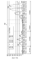
- FIG. 9 shows a graph 500 showing the relationship between the ejection frequency and the number of abnormal ejections.
- the discharge frequency is applied to the horizontal axis of the graph 500.
- the unit of the horizontal axis is kilohertz.
- the vertical axis of the graph 500 applies the number of nozzles whose ejection state has deteriorated.
- the unit of the number of abnormal discharges is applied.
- the ejection frequency is sequentially changed from 60 kilohertz to 105 kilohertz, continuous ejection is performed using a single drive waveform for each nozzle 25, and an arbitrary pattern for measuring the landing position error is formed on the paper P.
- the 1-on-M-off pattern can be applied as an arbitrary pattern for measuring the landing position error. Note that M is an integer of 2 or more.
- the pattern printing on the paper P was continuously performed on the plurality of paper P.
- the landing position shift for each nozzle was measured.
- a known measuring method can be applied to the measurement of the landing position shift.
- a nozzle for which the measured value of the landing position deviation exceeds the reference is determined as a nozzle in which the ejection state has deteriorated.
- the number of nozzles whose discharge state has deteriorated is plotted for each discharge frequency. 1st represents the measurement result of the first sheet P. 2nd represents the measurement result of the 150th sheet P. 3rd represents the measurement result of the 300th sheet P.
- a curve 502 represents the measurement result when the drive voltage having the reference amplitude is used.
- a curve 504 represents the measurement result when the drive voltage amplitude is 90% of the reference amplitude.
- a curve 506 represents the measurement result when the drive voltage amplitude is 80% of the reference amplitude.
- the drive voltage to which the reference amplitude is applied is defined based on the condition for ejecting a 2.6 picoliter droplet when the ejection frequency is 10 kilohertz.
- the ejection heads and inks used in the experiments conducted when creating the graph 500 are as shown in Table 1.
- the paper P used in the experiment performed when creating the graph 500 is inkjet coated paper.
- the recommended ejection frequency band 510 and the recommended ejection frequency band 511 are ejection frequency bands in which the number of nozzles whose ejection state has deteriorated is 50 or less.
- the ejection frequency band in which the number of nozzles whose ejection state has deteriorated exceeds 50 is the non-recommended ejection frequency band 512 and the non-recommended ejection frequency band 514.
- Curves 502, 504, and 506 show that the number of nozzles in which the ejection state deteriorates tends to decrease when the amplitude of the drive voltage is relatively reduced. That is, when the amplitude of the drive voltage is relatively increased, the droplet velocity relatively increases, while when the droplet velocity becomes too fast, the ejection state tends to deteriorate.
- the droplet velocity may be relatively reduced, while the droplet amount in one ejection may be relatively reduced.
- Relatively reducing the amplitude of the drive voltage for the purpose of suppressing the deterioration of the ejection state is not preferable from the viewpoint of securing a prescribed droplet amount. Therefore, it is recommended to select an arbitrary ejection frequency in the recommended ejection frequency band 510 and the recommended ejection frequency band 511 in order to secure the prescribed droplet amount and the stability of continuous ejection.
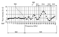
- FIG. 10 is a graph showing the relationship between the ejection frequency and the droplet velocity when a single drive waveform is applied.
- the discharge frequency is applied to the horizontal axis of the graph 520.
- the unit of the horizontal axis is kilohertz.
- the vertical axis of graph 520 applies drop velocity.
- the unit of the droplet velocity is meter per second.
- the recommended ejection frequency band 510, the recommended ejection frequency band 511, the non-recommended ejection frequency band 512, and the non-recommended ejection frequency band 514 shown in FIG. 10 The relationship between the ejection frequency and the droplet velocity shown in FIG. 10 is an example of droplet velocity information.
- the procedure for deriving the droplet velocity is as follows.
- the position where the distance from the nozzle surface 24 of the ejection head 21 is 300 micrometers is the first measurement position.
- the position where the distance from the nozzle surface 24 of the ejection head 21 is 500 micrometers is the second measurement position.
- the period required for the droplet to move from the first measurement value to the second measurement position is measured.
- a known method was applied to the measurement of the moving period of the droplet. Continuous ejection was performed for each ejection frequency, measurement was performed a plurality of times, and the average value of the measured values of the plurality of times was taken as the measurement result for each ejection frequency.
- the droplet velocity was calculated by dividing the distance from the first measured value to the second measured position by the measured value of the period.
- the ejection head 21 and the ink used for the measurement of the moving period of the droplet are as shown in Table 1.
- a drive voltage having a reference amplitude was applied as the drive voltage.
- the droplet volume is 2.6 picoliters when the ejection frequency is 10 kilohertz.
- the ejection frequency band in which the droplet velocity is constant in the curve 522 shown in FIG. 10 is defined as the first ejection frequency band 524.
- a droplet velocity in the first ejection frequency band 524 is set as a reference droplet velocity 528.
- the reference droplet velocity 528 described in the embodiment is an example of the first velocity.
- the first ejection frequency band 524 may include an ejection frequency band in which the difference between the droplet velocity and the reference droplet velocity 528 falls within a specified range, although the droplet velocity changes periodically.
- the ratio can be defined using the ratio of the droplet velocity to the maximum amplitude.
- the ratio of drop velocity to maximum amplitude may be 10 percent or less.
- a frequency band in which the ejection frequency is higher than 14 kilohertz and equal to or lower than 36 kilohertz may be included in the first ejection frequency band 524.
- the ejection frequency band in which the droplet velocity changes periodically and the ejection frequency band in which the difference from the reference droplet velocity 528 exceeds the specified range is referred to as a second ejection frequency band 526.
- the ejection frequency band in which the ejection frequency exceeds 36 kilohertz and 105 kilohertz or less is included in the second ejection frequency band 526.
- 86 kHz which is the minimum value of the curve 522
- 62 kHz which is the minimum value of the curve 522
- the droplet velocity shown in FIG. 10 will be described.
- the first ejection is in a state where it is not affected by resonance. That is, it is considered that the droplet in the first ejection behaves similarly to the case where an arbitrary ejection frequency in the first ejection frequency band 524 is set. Then, as the droplet velocity of the preceding droplet in continuous ejection, the droplet velocity corresponding to an arbitrary ejection frequency in the first ejection frequency band 524 can be applied.
- the droplet velocity shown in FIG. 10 represents the droplet velocity of the subsequent droplet affected by the preceding droplet for each ejection frequency. It can be said that the ejection frequency band in which the droplet velocity is smaller than the droplet velocity corresponding to the arbitrary ejection frequency in the first ejection frequency band 524 satisfies the condition that the subsequent droplet is not accelerated with respect to the preceding droplet.
- the control device 100 shown in FIG. 5 stores the droplet velocity information, which is the relationship between the ejection frequency and the droplet velocity when the single-shot drive voltage measured using the ejection head 21 is applied, and the ejection frequency setting unit. 140 may be used to set the ejection frequency based on the drop velocity information. Further, the control device 100 stores at least one of the recommended ejection frequency band 510 and the recommended ejection frequency band 511 extracted from the drop velocity information, and uses the ejection frequency setting unit 140 to recommend the recommended ejection frequency band 510 or the recommended ejection frequency band 510. The ejection frequency may be set based on the ejection frequency band 511.
- the reference droplet velocity 528 or less shown in the embodiment is an example of the first velocity or less.
- the drop velocity information to which the single shot drive waveform is applied has been exemplified, but the drop velocity information to which the continuous shot drive waveform is applied may be used. That is, it is possible to use drop velocity information in which a drive waveform including one or more ejection waveforms is applied to the pixel period.
- Formula 2 corresponds to the ejection frequency band in which the droplet velocity becomes equal to or lower than the reference droplet velocity 528 in the curve 522 shown in FIG. 10 and the slope of the curve 522 becomes 0 or less.
- the period T I can be a period from the start timing of the pressing period Tr in the final ejection pulse to the end timing of the drive waveform 400.
- the rotary encoder 15 is an example of a component of a medium speed information acquisition unit that acquires medium speed information indicating the moving speed of the medium.
- a linear scale or the like may be applied instead of the rotary encoder 15.
- the head control unit 136 shown in the embodiment is an example of an ejection frequency adjusting unit.
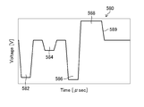
- FIG. 11 is a diagram showing a configuration example of a drive waveform for continuous shooting.
- the drive waveform for continuous shooting may be called a multi-pulse or the like.
- FIG. 11 shows the drive waveform 560 by applying the graph format.
- the horizontal axis of FIG. 11 applies the period.
- the unit of the period is microsecond.
- the vertical axis in FIG. 11 applies voltage.
- the unit of voltage is volts.
- the drive waveform 560 illustrated in FIG. 11 includes a first ejection waveform 562, a second ejection waveform 564, a third ejection waveform 566, and a first reverberation suppressing waveform 568.
- the first ejection waveform 562, the second ejection waveform 564, and the third ejection waveform 566 are selected according to the droplet size.
- the third ejection waveform 566 and the first reverberation suppressing waveform 568 are combined.
- the first ejection waveform 562, the third ejection waveform 566, and the first reverberation suppressing waveform 568 are combined.
- the first ejection waveform 562, the second ejection waveform 564, the third ejection waveform 566, and the first reverberation suppressing waveform 568 are combined.
- the first reverberation suppressing waveform 568 may be omitted in each droplet type.
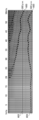
- FIG. 12 is a diagram showing the state of droplets for each ejection frequency when the drive waveform shown in FIG. 11 is applied.
- FIG. 13 is a diagram showing the state of medium drops for each ejection frequency when the drive waveform shown in FIG. 11 is applied.
- FIG. 14 is a diagram showing the state of large droplets for each ejection frequency when the drive waveform shown in FIG. 11 is applied.
- the droplets 600 ejected from the nozzle were continuously imaged for each ejection frequency, and photographs for each ejection frequency were created by arranging from the left to the right in the horizontal sequence in the order of the ejection frequency.
- the straight line with the reference numeral 602 shown in FIGS. 12 to 14 represents the first position.
- the straight line with the reference numeral 604 represents the second position 604.
- the relationship between the droplet speed and the ejection frequency band of the small droplet shown in FIG. 12 is different from the relationship between the droplet speed and the ejection frequency band of the medium droplet shown in FIG. Further, the relationship between the droplet speed and the ejection frequency band for the small droplet shown in FIG. 12 is different from the relationship between the droplet speed and the ejection frequency band for the large droplet shown in FIG.
- the valley of the amplitude is 53 kilohertz
- the valley of the amplitude is 56 kilohertz
- the ejection frequency of 56 kilohertz or higher becomes the trough of the amplitude. This is because in the drive waveform 560 shown in FIG. 11, the start timing of the first reverberation suppressing waveform 568 is deviated from the end timing of the third ejection waveform 566 by a half period of the resonance cycle. Inferred.
- the drive waveform 560 shown in FIG. 15 includes a fourth ejection waveform 582, a fifth ejection waveform 584, a sixth ejection waveform 586, and a second reverberation suppression waveform 588.
- the fourth ejection waveform 582, the fifth ejection waveform 584, and the sixth ejection waveform 586 are selected according to the droplet size.
- the sixth ejection waveform 586 and the second reverberation suppressing waveform 588 are combined.
- the fourth ejection waveform 582, the sixth ejection waveform 586, and the second reverberation suppressing waveform 588 are combined.
- the fourth ejection waveform 582, the fifth ejection waveform 584, the sixth ejection waveform 586, and the second reverberation suppressing waveform 588 are combined.
- the second reverberation suppressing waveform 588 may be omitted in each droplet type.
- the drive waveform 580 shown in FIG. 15 is an example of a drive waveform including a non-ejection waveform that is continuous with the final waveform element in the final ejection waveform.
- the sixth ejection waveform 586 is an example of the final ejection waveform.
- the rising waveform element of the sixth ejection waveform 586 is an example of the final waveform element.
- the second reverberation suppressing waveform 588 is an example of a non-ejection waveform.
- FIG. 16 is a diagram showing the state of droplets for each ejection frequency when the drive waveform shown in FIG. 15 is applied.
- FIG. 17 is a diagram showing the state of the medium droplet for each ejection frequency when the drive waveform shown in FIG. 15 is applied.
- FIG. 18 is a diagram showing the state of large droplets for each ejection frequency when the drive waveform shown in FIG. 15 is applied.
- the peaks of the amplitudes are substantially the same and the valleys of the amplitudes are almost equal. I am doing it. This is because the start timing of the second reverberation suppressing waveform 588 coincides with the end timing of the sixth ejection waveform 586, and the drawn waveform element 589 in the second reverberation suppressing waveform 588 contributes to reverberation suppression.
- One of the causes of the difference between the droplet velocity and the ejection frequency depending on the droplet type is the difference in the reverberation suppressing method.
- the refill vibration occurs from the timing when the droplet is ejected.
- the pressure chamber is changed in the pressure reducing direction at the final stage of the sixth ejection waveform 586 to suppress the reverberation.
- the pressure chamber 72 is expanded at the timing when the droplet is ejected. From this, it is assumed that the start timing of the vibration of the ink in the refill and the start timing of the refill match. In other words, since the pressure chamber is expanded at the timing of refilling the pressure chamber 72 with ink, it is presumed that the piezoelectric element 74 that supports the replenishment of the pressure chamber 72 with ink is operating.
- the pressure chamber 72 is changed in the pressurizing direction at the final stage of the first reverberation suppression waveform 568. That is, the first reverberation suppressing waveform 568 contracts the pressure chamber 72 after expanding the pressure chamber 72. That is, the first reverberation suppressing waveform 568 applies pressure in a direction to suppress the vibration of the ink in the refill, and as a result, a vibration different from the vibration of the ink in the refill is excited or the refill is not in time. It is inferred that the pressure chamber 72 was in the depressurized state at the discharge timing.
- the depressurized state of the pressure chamber 72 represents a state in which the pressure chamber 72 is contracted with respect to the static state.
- the reference droplet velocity 528 that is the droplet velocity in the first ejection frequency band 524 where the droplet velocity is constant.
- the ejection frequency of the ejection head 21 is set to an arbitrary ejection frequency in the ejection frequency band having the following droplet velocity. Thereby, as the ejection frequency of the ejection head 21, it is possible to apply the ejection frequency at which the subsequent droplet is not accelerated with respect to the preceding droplet.
- An arbitrary ejection frequency is set as the ejection frequency of the ejection head 21 in the ejection frequency band in which the droplet velocity is equal to or lower than the reference droplet velocity 528, and the inclination in the curve 522 representing the droplet velocity information is 0 or less. .. Thereby, in the setting of the ejection frequency of the ejection head 21, the condition of decelerating the subsequent droplet with respect to the preceding droplet can be applied.
- the period T I from the start timing of the final ejection pulse pressing period T r to the end timing of the drive waveform is (n+1/4) ⁇ T c ⁇ T I ⁇ (n+1/ when n is 1 or 2. 2) ⁇ T c is satisfied. This makes it possible to shift the ejection timing of the subsequent droplet with respect to the vibration caused by the ejection of the preceding droplet.
- the drive waveform 580 includes the second dereverberation waveform 588.
- the second reverberation suppressing waveform 588 is deviated from the end timing of the third ejection waveform 566 by a half period of the resonance period.
- the first reverberation suppressing waveform 568 suppresses reverberation by changing the pressure chamber in the pressure reducing direction at the final stage of the sixth ejection waveform 586.
- the head control unit 136 shown in FIGS. 5 and 6 can configure a head drive device that drives the ejection head 21.
- the head drive device may include the system control unit 102, the communication unit 104, the display control unit 114, and the like illustrated in FIG. Further, the head drive device and the ejection head 21 can form a head device.
Landscapes
- Particle Formation And Scattering Control In Inkjet Printers (AREA)
- Ink Jet (AREA)
Abstract
連続吐出安定性の確保と効率的な液滴吐出とを両立し得る、ヘッド駆動装置、ヘッド装置、印刷装置、及びヘッド駆動方法を提供する。駆動波形を取得する駆動波形取得部(138)、駆動電圧を生成する駆動電圧生成部(380)、単射における吐出周波数と液滴速度との関係を表す滴速度情報に基づいて、吐出周波数を設定する吐出周波数設定部(140)、駆動電圧を吐出ヘッドへ供給する駆動電圧供給部を備え、吐出周波数設定部は滴速度情報において液滴速度が第一速度以下の第二速度となる吐出周波数を吐出ヘッドの吐出周波数として設定する。
Description
本発明はヘッド駆動装置、ヘッド装置、印刷装置、及びヘッド駆動方法に係り、特に吐出ヘッドの駆動制御に関する。
インクジェット印刷機は一般に、ノズルの飛翔曲がり及びノズルの吐出異常に起因する白すじ等のバンディングの抑制が要求される。特に、シングルパス方式の印刷機は、一ノズルの異常に起因して、簡単にすじが発生してしまうため、より安定した吐出状態が要求される。
一方、近年のシングルパス方式の産業用インクジェット印刷機の動向として、より高い生産性が要求されている。生産性の向上は、画素を間引く手法又は一画素あたりの記録期間を短くする手法を適用して実現され得る。
一画素に対して一種類又は複数の種類の液滴を打ち分けることができる期間を一画素周期とした場合、画素周期に基づいてインクジェット印刷機の印刷可能速度が決定される。画素周期を短くするには、吐出ヘッドと液体との共振を適用した駆動方式が有効である。共振を用いた駆動方式は、効率的な規定の液滴量の吐出が実現される。
特許文献1は、共振を用いた駆動方式が適用されるインクジェット記録装置が記載されている。特許文献1に記載のインクジェット記録装置は、後続する画素周期において吐出した液滴の吐出速度を、先の画素周期において吐出させた液滴の吐出速度に対して同等又は遅くならないための駆動波形を開示している。
しかしながら、吐出ヘッドと液体とが共振するように、一画素周期内のパルス又はパルス群を接続した場合、先行する液滴に対して後続する液滴が加速され過ぎてしまう。これにより、連続的な液滴吐出の安定性が損なわれ得る。すなわち、連続的に液滴を吐出させる印刷を実施する際に、連続的な液滴吐出の安定性の確保と効率的な液滴吐出とを両立し得る吐出ヘッドの制御が必要である。
特許文献1に記載の発明は、先行する液滴である吐出パルスP1に基づき吐出される液滴の吐出速度に対して、後続する液滴である吐出パルスP2に基づき吐出される液滴の吐出速度が小さくなることを課題としている。
すなわち、特許文献1は、連続する画素周期において順に吐出させた液滴について、先行する液滴の吐出速度に対して後続する液滴の吐出速度が遅くならない条件として、キャンセルパルスC1の極性、キャンセルパルスC1のパルス幅、及びキャンセルパルスC1と吐出パルスとの間の期間を開示している。
一方、特許文献1に記載の発明では、先行する液滴に対して後続する液滴が加速され過ぎてしまう可能性がある。そうすると、特許文献1に記載の発明では、連続的な液滴吐出の安定性の確保が困難である。
特許文献1には、キャンセルパルスC1の終了タイミングから、一画素周期の終了タイミングまでの期間S1等に関する具体的な記載はない。図4等には期間S1が圧力室の固有振動周期の半周期ALと同一のように図示されている。しかし、後続する液滴の吐出速度を先行する液滴の吐出速度と同一とし、かつ、後続する液滴の吐出に対して残響振動の影響を抑制しようとすると、期間S1は圧力室の固有振動周期の半周期ALよりも十分に長い期間とされるべきである。以下に理由を説明する。
期間Sは必然的に吐出周波数に応じて変化する。図9A、図9B、図10A、及び図10Bに示すように、一周期目に吐出させた液滴の吐出速度に対して、二周期目以降に吐出させた液滴の吐出速度が同等又は小さくならない吐出周波数の条件は20キロヘルツ以下の帯域となる。特許文献1の段落<0048>の記載から、圧力室の固有振動周期の半周期ALは3.3マイクロ秒である。そうすると、期間S1は圧力室の固有振動周期の半周期ALよりも十分に長い期間となる。
更に、特許文献1に記載のように、キャンセルパルスC1を用いて残響振動をほぼ消失させることは現実的には困難である。残響振動をほぼ消失させるには、一周期目の吐出パルスの終了タイミングから二周期目の吐出パルスの開始タイミングまでに、十分に長い待機期間を設定する必要がある。
つまり、特許文献1は、段落<0047>に非実用的な期間S1と圧力室の固有振動周期の半周期ALとの関係が記載されているものの、吐出周波数の規定に適用可能であり、実用的な期間S1と圧力室の固有振動周期の半周期ALとの関係を開示していない。
本発明はこのような事情に鑑みてなされたもので、連続吐出安定性の確保と効率的な液滴吐出とを両立し得る、ヘッド駆動装置、ヘッド装置、印刷装置、及びヘッド駆動方法を提供することを目的とする。
上記目的を達成するために、次の発明態様を提供する。
第1態様に係るヘッド駆動装置は、一画素周期の駆動電圧に適用される駆動波形であり、駆動対象の吐出ヘッドの共振周期の二分の一の幅を有する吐出波形が一以上含まれる駆動波形を取得する駆動波形取得部と、駆動波形を用いて駆動電圧を生成する駆動電圧生成部と、一画素周期の分の駆動電圧を用いて液滴を吐出させた場合における吐出周波数と液滴速度との関係を表す滴速度情報に基づいて、吐出ヘッドの吐出周波数を設定する吐出周波数設定部と、吐出周波数設定部を用いて設定した吐出周波数を適用して、駆動電圧を吐出ヘッドへ供給する駆動電圧供給部と、を備え、吐出周波数設定部は、滴速度情報において液滴速度が一定となる吐出周波数帯域の液滴速度を第一速度とし、第一速度以下の液滴速度を第二速度とした場合、液滴速度が第二速度となる吐出周波数を、吐出ヘッドの吐出周波数として設定するヘッド駆動装置である。
第1態様によれば、滴速度情報において、液滴速度が一定となる吐出周波数帯域における液滴速度である第一速度以下の第二速度となる吐出周波数を、吐出ヘッドの吐出周波数に適用する。これにより、異なる画素を生成する二以上の液滴において、先行する先行滴に対して、先行滴に後続する後続滴が加速されず、連続吐出安定性の確保と効率的な液滴吐出との両立が可能となる。
画素周期は、一画素を生成する際に用いられる一以上の吐出波形の全期間を表す。画素周期の逆数は吐出周波数である。画素周期には一以上の吐出波形が含まれる。画素周期には非吐出波形が含まれていてもよい。
液滴速度は、任意の二点間の距離を、液滴が二点を通過する際に要する期間で除算して導出し得る。
第2態様は、第1態様のヘッド駆動装置において、吐出周波数設定部は、共振周期をTcとし、nを1又は2とし、第一駆動波形における最終の波形要素の始点から、第一駆動波形の次の画素周期に対応する第二駆動波形における最初の波形要素の始点までの期間をTIとした場合に、n×Tc≦TI≦(n+1/2)×Tcを満たす期間TIを用いて、吐出ヘッドの吐出周波数を設定する構成としてもよい。
第2態様によれば、先行滴の吐出に起因する振動に対して、後続滴の吐出タイミングが調整された吐出周波数を適用し得る。
第3態様は、第1態様のヘッド駆動装置において、吐出周波数設定部は、滴速度情報において吐出周波数に対する液滴速度を表す曲線の傾きが0以下となる吐出周波数を、吐出ヘッドの吐出周波数として設定する構成としてもよい。
第3態様によれば、先行滴に対して後続滴を減速させる条件が適用された吐出周波数を設定し得る。
第4態様は、第3態様のヘッド駆動装置において、吐吐出周波数設定部は、共振周期をTcとし、nを1又は2とし、第一駆動波形における最終の波形要素の始点から、第一駆動波形の次の画素周期に対応する第二駆動波形における最初の波形要素の始点までの期間をTIとした場合に、(n+1/4)×Tc≦TI≦(n+1/2)×Tcを満たす期間TIを用いて、吐出ヘッドの吐出周波数を設定する構成としてもよい。
第4態様によれば、先行滴の吐出に起因する振動に対して、後続滴の吐出タイミングが調整された吐出周波数を適用し得る。
第5態様は、第1態様から第4態様のいずれか一態様のヘッド駆動装置において、吐出周波数設定部は、滴速度情報において吐出周波数に対する液滴速度を表す曲線の極小値に対応する吐出周波数を、吐出ヘッドの吐出周波数として設定する構成としてもよい。
第5態様によれば、後続滴の液滴速度が最小となる条件が適用された吐出周波数を設定し得る。
第6態様は、第1態様から第5態様のいずれか一態様のヘッド駆動装置において、駆動波形取得部は、最終の吐出波形における最終の波形要素と連続する非吐出波形を含む吐出波形を取得する構成としてもよい。
第6態様によれば、複数の滴種を適用可能な場合に、全ての滴種における吐出周波数の最適化が可能となる。
第7態様は、第1態様から第5態様のいずれか一態様のヘッド駆動装置において、駆動波形取得部は、最終の吐出波形における最終の波形要素と非連続の非吐出波形を含む駆動波形を取得する構成としてもよい。
第7態様によれば、複数の滴種を適用可能な場合に、一種類以上の滴種における吐出周波数の最適化が可能となる。
第8態様は、第1態様から第7態様のいずれか一態様のヘッド駆動装置において、媒体の移動速度を表す媒体速度情報を取得する媒体速度情報取得部と、媒体速度情報を用いて吐出周波数を調整する吐出周波数調整部と、を備えた構成としてもよい。
第8態様によれば、媒体の移動速度を表す媒体速度情報に基づいて吐出周波数を調整し得る。
かかる態様において、媒体の移動速度の変動が吐出周波数の変動要因となる。媒体を移動させる媒体移動部は、媒体の移動速度の変動を一定範囲内とする構成が好ましい。
第9態様に係るヘッド装置は、吐出ヘッドと、吐出ヘッドを駆動するヘッド駆動装置と、を備え、ヘッド駆動装置は、一画素周期の駆動電圧に適用される駆動波形であり、駆動対象の吐出ヘッドの共振周期の二分の一の幅を有する吐出波形が一以上含まれる駆動波形を取得する駆動波形取得部と、駆動波形を用いて駆動電圧を生成する駆動電圧生成部と、一画素周期の分の駆動電圧を用いて液滴を吐出させた場合における吐出周波数と液滴速度との関係を表す滴速度情報に基づいて、吐出ヘッドの吐出周波数を設定する吐出周波数設定部と、吐出周波数設定部を用いて設定した吐出周波数を適用して、駆動電圧を吐出ヘッドへ供給する駆動電圧供給部と、を備え、吐出周波数設定部は、滴速度情報において液滴速度が一定となる吐出周波数帯域の液滴速度を第一速度とし、第一速度以下の液滴速度を第二速度とした場合、液滴速度が第二速度となる吐出周波数を、吐出ヘッドの吐出周波数として設定するヘッド装置である。
第9態様によれば、第1態様と同様の効果を得ることができる。
第9態様において、第2態様から第8態様で特定した事項と同様の事項を適宜組み合わせることができる。その場合、ヘッド駆動装置において特定される処理や機能を担う構成要素は、これに対応する処理や機能を担うヘッド装置の構成要素として把握することができる。
第10態様に係る印刷装置は、吐出ヘッドと、吐出ヘッドを駆動するヘッド駆動装置と、を備え、ヘッド駆動装置は、一画素周期の駆動電圧に適用される駆動波形であり、駆動対象の吐出ヘッドの共振周期の二分の一の幅を有する吐出波形が一以上含まれる駆動波形を取得する駆動波形取得部と、駆動波形を用いて駆動電圧を生成する駆動電圧生成部と、一画素周期の分の駆動電圧を用いて液滴を吐出させた場合における吐出周波数と液滴速度との関係を表す滴速度情報に基づいて、吐出ヘッドの吐出周波数を設定する吐出周波数設定部と、吐出周波数設定部を用いて設定した吐出周波数を適用して、駆動電圧を吐出ヘッドへ供給する駆動電圧供給部と、を備え、吐出周波数設定部は、滴速度情報において液滴速度が一定となる吐出周波数帯域の液滴速度を第一速度とし、第一速度以下の液滴速度を第二速度とした場合、液滴速度が第二速度となる吐出周波数を、吐出ヘッドの吐出周波数として設定する印刷装置である。
第10態様によれば、第1態様と同様の効果を得ることができる。
第10態様において、第2態様から第8態様で特定した事項と同様の事項を適宜組み合わせることができる。その場合、ヘッド駆動装置において特定される処理や機能を担う構成要素は、これに対応する処理や機能を担う印刷装置の構成要素として把握することができる。
第11態様に係るヘッド駆動方法は、一画素周期の駆動電圧に適用される駆動波形であり、駆動対象の吐出ヘッドの共振周期の二分の一の幅を有する吐出波形が一以上含まれる駆動波形を取得する駆動波形取得工程と、駆動波形を用いて駆動電圧を生成する駆動電圧生成工程と、一画素周期の分の駆動電圧を用いて液滴を吐出させた場合における吐出周波数と液滴速度との関係を表す滴速度情報に基づいて、吐出ヘッドの吐出周波数を設定する吐出周波数設定工程と、吐出周波数設定工程において設定した吐出周波数を適用して、駆動電圧を吐出ヘッドへ供給する駆動電圧供給工程と、を含み、吐出周波数設定工程は、滴速度情報において液滴速度が一定となる吐出周波数帯域の液滴速度を第一速度とし、第一速度以下の液滴速度を第二速度とした場合、液滴速度が第二速度となる吐出周波数を、吐出ヘッドの吐出周波数として設定するヘッド駆動方法である。
第11態様によれば、第1態様と同様の効果を得ることができる。
第11態様において、第2態様から第8態様で特定した事項と同様の事項を適宜組み合わせることができる。その場合、ヘッド駆動装置において特定される処理や機能を担う構成要素は、これに対応する処理や機能を担うヘッド駆動方法の構成要素として把握することができる。
本発明によれば、滴速度情報において、液滴速度が一定となる吐出周波数帯域における液滴速度である第一速度以下の第二速度となる吐出周波数を、吐出ヘッドの吐出周波数に適用する。これにより、異なる画素を生成する二以上の液滴において、先行する先行滴に対して、先行滴に後続する後続滴が加速されず、連続吐出安定性の確保と効率的な液滴吐出との両立が可能となる。
以下、添付図面に従って本発明の好ましい実施の形態について詳説する。本明細書では、同一の構成要素には同一の参照符号を付して、重複する説明は適宜省略することとする。
[インクジェット印刷装置]
〔全体構成〕
図1はインクジェット印刷装置の全体構成図である。インクジェット印刷装置1は、シングルパス方式を適用して、用紙Pに画像を印刷するデジタル印刷装置である。用紙Pは媒体、記録紙、及び印刷用紙等と称されるシート状の媒体を適用し得る。本明細書における印刷という用語は、画像形成及び画像記録等の用語と読み替えてもよい。
インクジェット印刷装置1は、用紙搬送部10、印刷部20、読取部30、給紙部40、及び集積部50を備える。以下、インクジェット印刷装置1の各部について詳細に説明する。
〔用紙搬送部〕
用紙搬送部10は給紙部40から供給された用紙Pを規定の搬送経路に沿って搬送する。用紙搬送部10は、走行するベルト11に用紙Pを吸着させて搬送する吸着ベルト搬送機構ある。
用紙搬送部10は、ベルト11、駆動ローラ12、従動ローラ13、モータ14、ロータリーエンコーダ15、及び吸引ユニット16を備える。ベルト11は、駆動ローラ12及び従動ローラ13に巻き掛けられる。駆動ローラ12は図示しない連結機構を介してモータ14が連結される。駆動ローラ12の回転軸はロータリーエンコーダ15が取り付けられる。
モータ14を駆動して駆動ローラ12を回転させる。駆動ローラ12及び従動ローラ13は、矢印線を用いて示す回転方向に回転する。駆動ローラ12及び従動ローラ13の回転に応じてベルト11は走行する。
ベルト11の用紙Pを吸着支持する用紙支持面11Aは、図示しない吸着穴が具備される。吸着穴は吸引ユニット16と連通する。吸引ユニット16は図示しない流路を介して、図示しないポンプと連結される。ポンプを動作させて吸引ユニット16に負圧を発生させる。吸引ユニット16に発生させた負圧はベルト11の吸着穴を介して用紙Pに作用する。これにより、用紙Pはベルト11に吸着支持される。
〔印刷部〕
印刷部20は、インクジェット方式を適用して、用紙Pに画像を印刷する。画像には、文字、記号、図形、及び線等が含まれてもよい。印刷部20は、吐出ヘッド21C、吐出ヘッド21M、吐出ヘッド21Y、及び吐出ヘッド21Kを備える。
吐出ヘッド21C、吐出ヘッド21M、吐出ヘッド21Y、及び吐出ヘッド21Kは、用紙Pの搬送方向に沿って、吐出ヘッド21C、吐出ヘッド21M、吐出ヘッド21Y、及び吐出ヘッド21Kの順に配置される。
以下、用紙Pの搬送方向は用紙搬送方向と記載する場合がある。また、用紙搬送方向と直交する方向であり、用紙Pの搬送面に平行となる方向である用紙Pの幅方向を用紙幅方向と記載する場合がある。図1に符号Xを用いて示す方向、及び符号Xを用いて示す方向と反対の方向は用紙幅方向である。符号Yを用いて示す方向は用紙搬送方向である。符号Zを用いて示す方向は鉛直方向である。
ここで、本明細書における直交という用語は、二方向が交差する角度が90度未満の場合、及び二方向が交差する角度が90度を超える場合であっても、二方向が交差する角度が90度の場合と同様の作用効果を得ることが可能な実質的な直交を含み得る。また、本明細書における平行という用語は、二方向が交差する場合であっても、二方向が平行の場合と同様の作用効果を得ることが可能な実質的な平行を含み得る。
吐出ヘッド21Cはシアンインクを吐出させる。吐出ヘッド21Mはマゼンタインクを吐出させる。吐出ヘッド21Yはイエローインクを吐出させる。吐出ヘッド21Kはブラックインクを吐出させる。
吐出ヘッド21C、吐出ヘッド21M、吐出ヘッド21Y、及び吐出ヘッド21Kは、用紙搬送方向と直交する用紙Pの幅方向について、用紙Pの全長に対応する有効記録幅を有するライン型ヘッドである。なお、ライン型ヘッドは、ラインヘッド、フルラインヘッド、及びページワイドヘッド等と呼ばれる場合があり得る。なお、実施形態に示す吐出ヘッド21C、吐出ヘッド21M、吐出ヘッド21Y、及び吐出ヘッド21Kは、駆動対象の吐出ヘッドの一例である。
〔読取部〕
読取部30は、用紙Pに印刷された画像を光学的に読み取り、読取画像を表す画像データを生成する。読取部30はインラインスキャナ31を備える。インラインスキャナ31は図示しない撮像デバイスを備える。撮像デバイスは、用紙Pに印刷された画像を撮像し、撮像画像を電気信号に変換する。
インラインスキャナ31は、ラインスキャナを適用し得る。撮像デバイスは、CCDリニアイメージセンサ及びCMOSリニアイメージセンサ等を適用し得る。CCDは、Charge-Coupled Deviceの省略語である。CMOSは、Complementary Metal Oxide Semiconductorの省略語である。
インラインスキャナ31は、照明装置及び信号処理回路を備える。照明装置は、読取対象に照明光を照射する。信号処理回路は、撮像デバイスから出力された電気信号を処理して画像データを生成する。なお、照明装置及び信号処理回路の図示は省略する。
〔給紙部〕
給紙部40は、図示しない給紙装置を備える。給紙装置は、給紙トレイ41に載置された用紙Pを一枚ずつ用紙搬送部10へ供給する。給紙部40は公知の構成を適用し得る。
〔集積部〕
集積部50は、用紙搬送部10から画像が印刷された用紙Pを受け取る。集積部50は、画像が印刷された用紙Pを集積トレイ51に集積する。
〔吐出ヘッドの詳細な説明〕
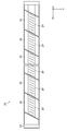
図2は吐出ヘッドの概略構成を示す底面図である。図2は吐出ヘッド21をノズル面24の側から見た図である。図1に示す吐出ヘッド21C、吐出ヘッド21M、吐出ヘッド21Y、及び吐出ヘッド21Kは、同一の構造を適用し得る。図2には、吐出ヘッド21C、吐出ヘッド21M、吐出ヘッド21Y、及び吐出ヘッド21Kの任意の一つとして吐出ヘッド21を示す。
吐出ヘッド21は、吐出ヘッド21の長手方向について、複数のヘッドモジュール22を繋ぎ合わせた構造を有する。複数のヘッドモジュール22は同一の構造を適用し得る。なお、ヘッドモジュール22の数に制限はなく、使用される用紙Pの用紙幅方向の全長に応じて適宜決められる。
ベースフレーム23は、複数のヘッドモジュール22が取り付けられる。ベースフレーム23は、取り付け可能なヘッドモジュール22の数に応じた取付部を備える。ベースフレーム23は、ヘッドモジュール22の位置を調整する調整部を備える。なお、取付部及び調整部の図示は省略する。
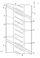
図3は吐出ヘッドのノズル面の構成例を概略的に示す図である。ヘッドモジュール22は、ノズル面24に複数のノズル25が形成される。各ヘッドモジュール22は、それぞれのノズル面24が同一平面を構成するように、鉛直方向の位置が調整される。
複数のノズル25は、規定の印刷解像度を実現する配置密度を有する。複数のノズル25はマトリクス配置が適用される。複数のノズル25を媒体幅方向に投影させた投影ノズル列は、媒体幅方向に沿って複数のノズル25が概ね等間隔に配置される一列のノズル列と等価である。
概ね等間隔とは、吐出ヘッドを用いてドットの形成が可能な打滴点として、実質的に等間隔であることを意味している。例えば、製造上の誤差及び着弾干渉に起因する用紙Pにおける液滴の移動等を考慮して僅かに間隔を異ならせたノズル25が含まれる場合も、等間隔の概念に含まれる。本明細書では、ノズル25の位置関係を記述する場合、特に断らない限り、投影ノズル列におけるノズル25の位置関係を意味することとする。
マトリクス配置における列方向は行方向に対して斜めに交差する方向であってよい。また、行方向は用紙幅方向に平行となる方向でもよいし、用紙幅方向に非平行となる方向でもよい。ヘッドモジュール22のノズル25の配置はマトリクス配置に限定されない。ノズル25の配置の例として、一列の直線配置、V字形状配置、及びV字形状配置を繰り返し単位とするW字形状配置等が挙げられる。
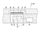
図4は吐出ヘッドの構造例を示す断面図である。イジェクタ70は、ノズル25、圧力室72、及び圧電素子74を備える。ノズル25は、ノズル流路76を介して圧力室72と連通する。圧力室72は個別供給路78を介して供給側共通支流路80と連通する。
圧力室72の天面を構成する振動板82は、圧電素子74の下部電極に相当する共通電極として機能する導電層を備える。なお、導電層の図示は省略する。圧力室72、その他の流路部分の壁部、及び振動板82などはシリコンによって作製することができる。
振動板82の材質はシリコンに限らず、樹脂などの非導電性材料によって形成する態様も可能である。振動板82自体をステンレス鋼などの金属材料によって構成し、共通電極を兼ねる振動板としてもよい。
振動板82に対して圧電素子74が積層された構造により、圧電ユニモルフアクチュエータが構成される。圧電素子74の上部電極である個別電極84に駆動電圧を印加して圧電体86を変形させ、振動板82を撓ませて圧力室72の容積を変化させる。圧力室72の容積変化に伴う圧力変化がインクに作用して、ノズル25からインクが吐出される。
インク吐出の後に圧電素子74が元の状態に戻る際に、供給側共通支流路80から個別供給路78を通って新しいインクが圧力室72に充填される。圧力室72にインクが充填される動作をリフィルという。
圧力室72の平面視形状については、特に限定はなく、四角形その他の多角形、円形、或いは楕円形など、様々な形態があり得る。カバープレート88は圧電素子74の可動空間90を保し、かつ、圧電素子74の周囲を封止する部材である。
カバープレート88の上方には、図示しない供給側インク室、及び回収側インク室が形成される。供給側インク室は、図示しない連通路を介して、図示しない供給側共通本流路に連結される。回収側インク室は、図示しない連通路を介して、図示しない回収側共通本流路に連結されている。
〔インクジェット印刷装置の機能ブロック〕
図5はインクジェット印刷装置の機能ブロック図である。インクジェット印刷装置1は、制御装置100を用いて制御される。制御装置100は、コンピュータのハードウェアとソフトウェアとのを組み合わせて実現し得る。ソフトウェアはプログラムと同義である。
制御装置100は、システム制御部102を備える。システム制御部102は、中央演算装置及び周辺回路等から構成される。システム制御部102は制御プログラムに従って動作する。
制御装置100は、プログラム格納部110を備える。プログラム格納部110は、システム制御部102が実行するプログラムが格納される。制御装置100は、プログラムを実行する際に使用される各種パラメータを記憶するパラメータ記憶部を備える。プログラム格納部110はパラメータ記憶部と兼用されてもよい。
制御装置100は、通信部104を備える。通信部104は、規定の通信インターフェースを備える。制御装置100は通信部104を介してホストコンピュータ105と通信可能に接続される。制御装置100は通信部104を介してホストコンピュータ105との間でデータの送受信を実施し得る。制御装置100とホストコンピュータ105との接続は、有線、無線、又は有線と無線との組み合わせを適用し得る。通信部104は通信を高速化するバッファメモリを備えてもよい。
制御装置100は、画像データ取得部106を備える。画像データ取得部106は、印刷対象の画像を表す画像データを取得するインターフェースである。画像データの形式は限定されない。画像データの例として、RGBの各色を256階調で表したRGB画像が挙げられる。RGBに代わりCMYKを適用してもよい。また、各色の階調数は256階調に制限されない。
なお、RGBのRは赤を表す。Bは青を表す。Gは緑を表す。また、CMYKのCはシアンを表す。Mはマゼンタを表す。Yはイエローを表す。Kはブラックを表す。
画像データ取得部106は、インクジェット印刷装置1の外部又はインクジェット印刷装置1の内部の信号処理部から画像データを取り込むデータ入力端子を適用し得る。画像データ取得部106は、有線又は無線の通信インターフェースを適用し得る。画像データ取得部106は、メモリカード等の可搬型の記憶媒体の読み書きを行うメディアインターフェースを適用し得る。
画像データ取得部106は、データ入力端子、通信インターフェース、及びメディアインターフェースの組み合わせを適用し得る。通信部104は、画像データ取得部106の機能を担うことが可能である。
制御装置100は、メモリ108を備える。メモリ108は、画像データ取得部106を用いて取得した画像データを含む各種データを一次記憶する。
制御装置100は、表示制御部114を備える。表示制御部114は、表示装置115を用いて表示させる各種情報を表す表示信号を表示装置115へ送信する。表示装置115はモニタ装置を適用し得る。表示制御部114は、モニタ装置を制御するディスプレイドライバーとして機能する。
制御装置100は、操作制御部116を備える。操作制御部116は、操作装置117から送信される入力信号を取得する入力インターフェースである。操作装置117は、キーボード及びマウス等を適用し得る。
表示装置115及び操作装置117は、ユーザインターフェースを構成する。タッチパネル方式のディスプレイ装置を適用して、表示装置115と操作装置117とを一体に構成してもよい。
オペレータは、表示装置115の画面に表示される内容を見ながら、操作装置117を操作して、印刷条件の入力、印刷モードの選択等の各種情報の入力、各種情報の編集、及び各種情報の検索等を実施し得る。オペレータは、表示装置115の画面を通じて入力内容等を確認し得る。
制御装置100は、画像処理部118を備える。画像処理部118は、補正処理部120及びハーフトーン処理部122を備える。補正処理部120は、画像データに対する各種変換処理及び各種補正処理を実施する。
変換処理は、画素数変換、階調変換、及び色変換等を含み得る。補正処理は、吐出ヘッド21の特性に合わせた濃度補正、及び異常ノズルに起因する画像欠陥の視認性を補正する異常ノズル補正等を含み得る。
ハーフトーン処理部122は、CMYK各色の画像データを二値又は多値のドット画像データへ変換するハーフトーン処理を行う。ハーフトーン処理規則の例として、ディザ法及び誤差拡散法など、公知のハーフトーン処理規則が挙げられる。ハーフトーン処理は、一般に、三以上の階調値を有する多階調の画像データを量子化して、吐出ヘッド21を用いて記録可能な階調値であり、画像データの階調値未満の階調値を有するデータに変換する処理である。
インクジェット印刷装置1の吐出ヘッド21は、大滴、中滴、及び小滴の三種類の滴種を打ち分けることが可能である。ハーフトーン処理部122は、256階調等の多階調の各色の分版画像データを、大滴、中滴、小滴、及び滴なしの四値の信号に変換する。大滴を吐出した場合、用紙Pには大ドットが形成され、中滴を吐出した場合、用紙Pには中ドットが形成され、小滴を吐出した場合、用紙Pには小ドットが形成される。
制御装置100は、給紙制御部130を備える。給紙制御部130は、システム制御部102から送信される指令信号に基づいて、給紙部40の動作を制御する。
制御装置100は、搬送制御部134を備える。搬送制御部134は、システム制御部102から送信される指令信号に基づいて、用紙搬送部10の動作を制御する。例えば、搬送制御部134は、図1に示すモータ14の動作を制御する、モータドライバーを備える。
制御装置100は、図示しないエンコーダ出力信号取得部を介して、ロータリーエンコーダ15の出力信号を取得する。制御装置100は、ロータリーエンコーダ15の出力信号から吐出トリガ信号を生成する。吐出ヘッド21の吐出タイミングは、ロータリーエンコーダ15の出力信号に同期させる。これにより、液滴の着弾位置を高精度に決定し得る。
制御装置100は、ヘッド制御部136を備える。ヘッド制御部136は、システム制御部102から送信される指令信号に基づいて、吐出ヘッド21の駆動を制御する。ここでいう指令信号には吐出トリガが含まれる。ヘッド制御部136は、ハーフトーン処理部122のハーフトーン処理を経て生成された各色のドットデータに基づいて吐出ヘッド21の駆動を制御し、用紙Pに画像を形成させる。
ヘッド制御部136は、駆動波形取得部138及び図5に図示しない駆動電圧生成部を備える。駆動波形取得部138は、駆動波形を取得する。駆動波形を取得する態様として、入力インターフェースを介して外部装置から駆動波形を取得する態様、制御装置100の内部の記憶装置から駆動波形を読み出す態様等が挙げられる。
駆動電圧生成部は、駆動波形取得部138を用いて取得した駆動波形に基づいて、駆動電圧を生成する。駆動電圧生成部は、駆動波形に対して電圧増幅及び電流増幅を行い、規定の電圧値を有する駆動電圧を生成する。なお、駆動電圧生成部は、符号380を付して図6に示す。
ヘッド制御部136は、図示しない駆動電圧出力回路を備える。駆動電圧出力回路は、吐出ヘッド21に具備される圧電素子74へ駆動電圧を供給する。なお、実施形態に示す駆動電圧出力部は、駆動電圧供給部の構成要素の一例である。
制御装置100は、図示しない入力インターフェースを介して、読取部30の出力信号を取得する。制御装置100は、読取部30の出力信号を用いて、吐出ヘッド21の吐出状態を把握する。吐出ヘッド21の吐出状態の例として、異常ノズルの発生が挙げられる。異常ノズルは、液滴を吐出しない不吐ノズル、及び液滴の飛翔曲がり発生している飛翔曲がりノズル等が含まれ得る。
制御装置100は、駆動波形取得部138を備える。駆動波形取得部138は図6に示す波形データメモリ366へ駆動波形を記憶する。駆動波形取得部138はホストコンピュータ105等の外部装置から駆動波形を取得してもよいし、図示しない入力インターフェースを介して、記憶媒体から駆動波形を取得してもよい。図示しない入力インターフェースとして、記憶媒体を着脱可能に構成されたスロット等を適用し得る。
制御装置100は、吐出周波数設定部140を備える。吐出周波数設定部140は吐出周波数の情報をヘッド制御部136へ送信する。ヘッド制御部136は、吐出周波数設定部140から送信された吐出周波数を適用して、吐出ヘッド21の吐出タイミングを制御する。
制御装置100は、搬送速度設定部142を備える。搬送速度設定部142は用紙Pの搬送速度を設定する。搬送速度設定部142は、操作装置117を用いて入力された用紙Pの搬送速度の情報に基づき、用紙Pの搬送速度を設定し得る。搬送速度設定部142は、搬送速度の情報を吐出周波数設定部140へ送信する。吐出周波数設定部140は、搬送速度設定部142から送信された用紙Pの搬送速度の情報に基づいて、吐出周波数を設定する。
制御装置100は、一台又は複数台のコンピュータによって実現することが可能である。制御装置100の処理部は、1つ又は複数のCPU(Central Processing Unit)を用いて構成し得る。一つ又は複数のCPUは、プログラム格納部110に保存されているプログラムがCPUにロードされることにより動作する。制御装置100の処理機能の一部又は全部は、DSP(digital signal processor)及びFPGA(field-programmable gate array)等に代表される集積回路を用いて実現し得る。
〔ヘッド制御部の詳細な説明〕
図6はヘッド制御部の構成例を示す機能ブロック図である。図6には、吐出ヘッド21が第一ヘッドモジュール22A、及び第二ヘッドモジュール22Bを備え、第一ヘッドモジュール22Aへ駆動電圧Aを供給し、第二ヘッドモジュール22Bへ駆動電圧Bを供給する場合のヘッド制御部136の構成例を示す。
ヘッド制御部136は、画像データメモリ362、画像データ転送制御回路364、吐出タイミング制御部365、波形データメモリ366、及び駆動電圧制御回路368を備える。
また、ヘッド制御部136は、第一デジタルアナログ変換器379A、第二デジタルアナログ変換器379B、第一電力増幅回路377A、及び第二電力増幅回路377Bを備える。
画像データ転送制御回路364は、図示しないラッチ信号送信回路が含まれる。画像データ転送制御回路364から吐出ヘッド21へ、適宜のタイミングでデータラッチ信号が出力される。なお、データラッチ信号は、図6に示すデータラッチA及びデータラッチBの総称である。
画像データメモリ362は、図5に示すハーフトーン処理部122を用いて生成したドットデータを記憶する。波形データメモリ366は、駆動波形を示すデジタルデータを記憶する。波形データメモリ366は、図5に示す駆動波形取得部138を用いて取得した駆動波形を記憶する。波形データメモリ366は、駆動波形取得部138を介して、図示しない駆動波形生成部を用いて生成された駆動波形を記憶してもよい。
画像データメモリ362は、印刷実行中の用紙Pの搬送と同期して、印刷対象の画像データに対応するドットデータを取得する。吐出タイミング制御部365は、ロータリーエンコーダ15の出力信号に基づくトリガ信号を取得する。吐出タイミング制御部365は、画像データ転送制御回路364及び駆動電圧制御回路368へ、スタートトリガ信号を送信する。
画像データ転送制御回路364は、スタートトリガ信号を受信し、スタートトリガ信号に同期させて吐出ヘッド21へドットデータを転送する。駆動電圧制御回路368は、スタートトリガ信号を受信し、スタートトリガ信号に同期させて、第一デジタルアナログ変換器379A及び第二デジタルアナログ変換器379Bへ駆動波形を転送する。これにより、画像データに応じた選択的なドロップオンデマンドの吐出駆動制御に基づく印刷を実現する。
第一デジタルアナログ変換器379A及び第二デジタルアナログ変換器379Bは、デジタル形式の駆動波形をアナログ形式の電圧波形へ変換する。第一デジタルアナログ変換器379Aから出力される電圧波形は、第一電力増幅回路377Aを用いて圧電素子の駆動に適した電流及び電圧に増幅される。同様に、第二デジタルアナログ変換器379Bから出力される電圧波形は、第二電力増幅回路377Bを用いて圧電素子の駆動に適した電流及び電圧に増幅される。
第一電力増幅回路377Aから出力された駆動電圧Aは、第一ヘッドモジュール22Aへ供給される。第二電力増幅回路377Bから出力された駆動電圧Bは、第二ヘッドモジュール22Bへ供給される。
第一電力増幅回路377A、第二電力増幅回路377B、第一デジタルアナログ変換器379A、及び第二デジタルアナログ変換器379Bは、駆動波形を用いて駆動電圧を生成する、駆動電圧生成部380を構成する。
画像データ転送制御回路364は、画像データメモリ362に記憶したドットデータを基に、第一ヘッドモジュール22A及び第二ヘッドモジュール22Bのノズル制御データを、それぞれ第一ヘッドモジュール22A及び第二ヘッドモジュール22Bへ転送する制御を行う。
ノズル制御データは、ノズルの吐出駆動又は非駆動を決定する制御データである。画像データ転送制御回路364は、ノズル制御データを各ヘッドモジュール22へ転送する。これにより、ノズルごとに吐出駆動又は非駆動が制御される。
画像データ転送制御回路364から出力されるノズル制御データを第一ヘッドモジュール22Aに伝送する第一ノズル制御データ伝送路392Aは、画像データバス、データバス、又は画像バスなどと呼ばれる。第二ノズル制御データ伝送路392Bも同様である。
第一ノズル制御データ伝送路392A及び第二ノズル制御データ伝送路392Bは、複数の信号線を含んで構成される。第一ノズル制御データ伝送路392A及び第二ノズル制御データ伝送路392Bの一端は画像データ転送制御回路364の出力端子に接続される。
第一ノズル制御データ伝送路392Aの他端は、第一コネクタ394Aを介して第一ヘッドモジュール22Aと接続される。第二ノズル制御データ伝送路392Bの他端は、第二コネクタ394Bを介して第二ヘッドモジュール22Bと接続される。なお、実施形態に記載の第一コネクタ394A及び第二コネクタ394Bは、駆動電圧供給部の構成要素の一例とし得る。
第一ノズル制御データ伝送路392A及び第二ノズル制御データ伝送路392Bは、画像データ転送制御回路364、及び駆動電圧制御回路368等を実装した電気回路基板の電気配線パターンによって構成し得る。
第一ノズル制御データ伝送路392A及び第二ノズル制御データ伝送路392Bは、ワイヤーハーネスを適用し得る。第一ノズル制御データ伝送路392A及び第二ノズル制御データ伝送路392Bは、は、電気回路基板の配線パターンとワイヤーハーネスとを組み合わせて構成してもよい。
データラッチAを伝送する第一ラッチ信号線396Aは、第一コネクタ394Aを介して第一ヘッドモジュール22Aの信号入力端子と接続される。データラッチBを伝送する第二ラッチ信号線396Bは、第二コネクタ394Bを介して第二ヘッドモジュール22Bの信号入力端子と接続される。
データラッチAは、第一ノズル制御データ伝送路392Aを経由して転送したノズルデータ信号を、第一ヘッドモジュール22Aのノズルデータとして設定するために、画像データ転送制御回路364から、第一ヘッドモジュール22Aに対して必要なタイミングで送信される。
データラッチBは、第二ノズル制御データ伝送路392Bを経由して転送したノズルデータ信号を、第二ヘッドモジュール22Bのノズルデータとして設定するために、画像データ転送制御回路364から第二ヘッドモジュール22Bに対して必要なタイミングで送信される。
画像データ転送制御回路364は、第一ノズル制御データ伝送路392Aを介して、第一ヘッドモジュール22Aへ一定量の画像データを送信したタイミングにおいて、第一ヘッドモジュール22AへデータラッチAを送信する。
画像データ転送制御回路364は、第二ノズル制御データ伝送路392Bを介して、第二ヘッドモジュール22Bへ一定量の画像データを送信したタイミングにおいて、第二ヘッドモジュール22BへデータラッチBを送信する。
データラッチAが表すタイミングにおいて、第一ヘッドモジュール22Aにおける圧電素子の吐出駆動又は非駆動のデータが確定する。また、データラッチBが表すタイミングにおいて、第二ヘッドモジュール22Bにおける圧電素子の吐出駆動又は非駆動のデータが確定する。その後、第一ヘッドモジュール22A及び第二ヘッドモジュール22Bへ駆動電圧が供給され、吐出駆動が実施される圧電素子は変形してインクを吐出させる。こうして吐出させたインクを媒体へ付着させ、所望の解像度の印刷が行われる。
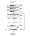
[吐出ヘッド駆動方法のフローチャート]
図7はヘッド駆動方法の手順を示すフローチャートである。吐出ヘッド駆動方法は、駆動波形取得工程S10、搬送速度設定工程S12、駆動電圧生成工程S14、エンコーダ信号入力工程S16、スタートトリガ信号生成工程S18、スタートトリガ信号出力工程S20、駆動電圧出力工程S22、吐出終了指令判定工程S24を含む。
駆動波形取得工程S10では、図6に示すヘッド制御部136は図5に示す駆動波形取得部138を介して駆動波形を取得する。ヘッド制御部136は、画像データメモリ362へ駆動波形を記憶する。駆動波形取得工程S10の後に搬送速度設定工程S12へ進む。
搬送速度設定工程S12では、搬送速度設定部142は、用紙Pの搬送速度を設定する。搬送速度設定部142は用紙Pの搬送速度の情報を吐出周波数設定部140へ送信する。吐出周波数設定部140は用紙Pの搬送速度の情報に基づき吐出周波数を設定する。吐出周波数設定部140は、吐出周波数の情報を吐出タイミング制御部365へ送信する。
搬送速度設定工程S12の後に駆動電圧生成工程S14へ進む。実施形態に記載の搬送速度設定工程S12における吐出周波数を設定する工程は、吐出周波数設定工程の一例である。
駆動電圧生成工程S14では、駆動電圧生成部380は駆動波形を用いて駆動電圧を生成する。駆動電圧生成工程S14の後にエンコーダ信号入力工程S16へ進む。
エンコーダ信号入力工程S16では、ヘッド制御部136はロータリーエンコーダ15の出力信号を取得する。エンコーダ信号入力工程S16の後にスタートトリガ信号生成工程S18へ進む。
スタートトリガ信号生成工程S18では、吐出タイミング制御部365は、搬送速度設定工程S12において設定された用紙Pの搬送速度に基づく吐出周波数及びエンコーダ信号を用いて、スタートトリガ信号を生成する。
すなわち、搬送速度設定工程S12において設定される、用紙Pの搬送速度に基づく吐出周波数は目標の吐出周波数である。用紙Pの搬送速度の変動が発生しない場合は、吐出周波数は固定でよいが、現実には用紙Pの搬送速度はばらつきがあり、吐出タイミングは用紙Pの搬送速度のばらつきに応じて調整する必要がある。
換言すると、スタートトリガ信号生成工程S18では、用紙Pの搬送速度のばらつきに応じた吐出周波数の調整に適用するスタートトリガ信号を生成する。現実の吐出周波数は、目標値に対して規定の範囲で調整される。スタートトリガ信号生成工程S18の後にスタートトリガ信号出力工程S20へ進む。
スタートトリガ信号出力工程S20では、吐出タイミング制御部365は、画像データ転送制御回路364及び駆動電圧制御回路368へ、スタートトリガ信号を送信する。スタートトリガ信号出力工程S20の後に駆動電圧出力工程S22へ進む。
駆動電圧出力工程S22では、駆動電圧出力部は駆動電圧を出力する。駆動電圧は、第一コネクタ394A及び第二コネクタ394Bを介してヘッド制御部136から吐出ヘッド21へ供給される。駆動電圧出力工程S22の後に吐出終了指令判定工程S24へ進む。なお、駆動電圧出力工程S22は駆動電圧供給工程の一例である。
吐出終了指令判定工程S24では、ヘッド制御部136は吐出終了指令を取得したか否かを判定する。吐出終了指令の取得態様として、印刷ジョブを終了する際に取得する態様及び異常発生等に伴う印刷ジョブを中止する際に取得する態様などが挙げられる。
吐出終了指令判定工程S24において、ヘッド制御部136が吐出終了指令を取得していない場合はNo判定となり、吐出終了指令判定工程S24においてYes判定となるまで、エンコーダ信号入力工程S16から駆動電圧出力工程S22までの各工程を繰り返し実施する。
一方、吐出終了指令判定工程S24において、ヘッド制御部136が吐出終了指令を取得した場合はYes判定となり、規定の終了処理が実行され、印刷が終了される。
[駆動波形の説明]
図8は駆動波形の一例を示す図である。図8にはグラフ形式を適用して駆動波形400を示す。図8の横軸は期間を適用する。期間の単位はマイクロ秒である。図8の横軸は電圧を適用する。電圧の単位はボルトである。図8には、一画素周期TPの駆動波形400を二画素周期分示す。
なお、図8に示す二画素周期分の駆動波形400のうち、先行滴に対応する駆動波形400から生成される駆動電圧は第一駆動電圧の一例である。また、後続滴に対応する駆動波形400から生成される駆動電圧は第二駆動電圧の一例である。
駆動波形400は、吐出波形402及び残響抑制波形404が含まれる。吐出波形402はインク吐出に寄与する波形である。残響抑制波形404はインク吐出の後におけるインクの振動の抑制に寄与する波形である。なお、実施形態に記載の駆動波形400は、吐出波形が一以上含まれる駆動波形の一例である。
吐出波形402は、第一波形要素410、第二波形要素412、及び第三波形要素414が含まれる。第一波形要素410は、静定状態の圧力室72を膨張させる波形要素である。第二波形要素412は、圧力室72の膨張させた状態を維持する波形要素である。第三波形要素414は、膨張させた圧力室72を収縮させる波形要素である。
符号Tfは引き期間を表す。引き期間Tfは、第一波形要素410が圧電素子74へ印加される期間である。符号Trは押し期間を表す。押し期間Trは、第三波形要素414が圧電素子74へ印加される期間である。
符号Twは、吐出波形402の幅を表す。吐出波形402の幅はパルス幅と呼ばれる場合があり得る。吐出波形402の幅TWは、引き期間Tfの終了タイミングから押し期間Trの開始タイミングまでの期間である。
残響抑制波形404は、第四波形要素416及び第五波形要素418が含まれる。第四波形要素416は、圧力室72の静定状態よりも収縮させた状態を維持する波形要素である。第五波形要素418は、圧力室72を静定状態に戻す波形要素である。第五波形要素418の期間は、残響を打ち消す残響打消期間Tnegである。
なお、圧力室72の静定状態とは、非吐出の際の圧力室72の状態である。圧力室72の静定状態は、圧電素子74への電圧非印加を適用して実現してもよいし、圧電素子74へ一定電圧を印加して実現してもよい。実施形態に示す圧力室72は、液室の一例である。
画素周期TPは、注目する駆動波形400における引き期間Tfの開始タイミングから、次の駆動波形400における引き期間Tfの開始タイミングまでの期間を表す。画素周期の逆数は吐出周波数である。
図8に示す符号TIは、吐出波形402の押し期間Trの開始タイミングから、吐出波形402の終了タイミングまでの期間を表す。なお、吐出波形402の終了タイミングは、次の画素周期TPにおける吐出波形402の開始タイミングと一致する。期間TIは共振周期Tcを用いて規定される。期間TIの詳細は後述する。
図8には、一つの吐出波形402を含む駆動波形400を示したが、駆動波形400は複数の吐出波形402を含み得る。複数の吐出波形402を含む駆動波形400は、複数の吐出波形402から一つ以上の吐出波形402を適宜選択して、二種類以上の液滴のサイズを実現し得る。
[課題の詳細な説明]
一画素周期内の駆動波形400において、パルス幅及びパルス間隔に共振を適用して吐出を実現する方式は、効率的に液滴量を確保し、一画素周期内の駆動波形400の最終波形として残響抑制波形404を適用して、次の画素周期における吐出波形402の印加の直前まで、圧力室72の内部におけるインクの振動を積極的に低減させる技術が併用され得る。
しかし、単純に残響抑制波形404を適用するだけでは、インク振動を打ち消しきれずに、次の画素周期の開始タイミング次第では、吐出させた液滴が加速されたり、減速されたりする。特に、液滴が加速される場合はメニスカスの振幅が大きくなり、連続印刷中に異常ノズルの増加が見られる。
なお、連続印刷とは、二枚以上の用紙Pに対し連続的に実施される印刷を示す。連続印刷は、同一の画像データを適用してもよいし、異なる画像データを適用してもよい。各用紙Pへの印刷間は規定のインターバルが設定されてもよい。
一方、残響を抑制するための期間を長くすることは、安定した吐出を実現し得るが、印刷速度の低下に直結し得る。印刷速度の低下は最小限に抑える必要がある。印刷速度は単位時間当たりの印刷枚数を適用し得る。
ここで、特許文献1の段落<0047>には、圧力室の固有振動周期の半周期をALとした場合に、残響を抑制するための期間として、吐出パルスP1からキャンセルパルスC1までの期間を2×ALとし、キャンセルパルスC1の期間をALとし、キャンセルパルスC1から吐出パルスP2までの期間を5×ALに設定すると記載されている。すなわち、特許文献1に記載の発明では、残響を抑制するための期間を8×ALと設定している。
図9A等のグラフから、吐出パルスP1による液滴の吐出速度に対して、吐出パルスP2による液滴の吐出速度が遅くならない吐出周波数の条件は、現実には20キロヘルツ以下と読み取れる。同文献の段落<0048>には、ALは3.3マイクロ秒と記載されている。これらの数値に基づき、吐出パルスP1の終了タイミングから吐出パルスP2の開始タイミングまでの期間を算出すると、40.6マイクロ秒となる。40.6マイクロ秒は、12×ALから13×ALの間の数値である。
すなわち、特許文献1は、キャンセルパルスC1を用いて安定した吐出を実現する条件を開示しているものの、印刷速度の低下を最小限に抑えることを開示していない。換言すると、特許文献1は、一周期目の吐出パルスの終了タイミングから二周期目の吐出パルスの開始タイミングまでの期間を、圧力室の固有振動周期の半周期ALに対して十倍以上として、安定した吐出を実現することを開示している。
本実施形態に係るヘッド駆動方法は、一画素周期の駆動波形に共振を用いて効率的な液滴吐出を実現し、かつ、連続印刷中においても安定した液滴吐出が可能な吐出周波数が適用される。
[吐出周波数の説明]
共振を用いた駆動波形が適用される連続吐出では、先行滴及び先行滴の一画素周期の後に吐出される後続滴について、先行滴に対して後続滴が加速されない吐出周波数が適用される。共振を用いた駆動波形とは、吐出波形のパルス幅が、共振周期のTcの半周期であるTc/2とされる駆動波形である。
共振周期Tcは、吐出ヘッド21のヘルムホルツ固有振動周期である。共振周期Tcは、インク流路の構造、音響要素としてのインクの物性値、圧電素子の物性値等から定まる振動系全体の固有周期である。共振周期Tcは、吐出ヘッドの設計値から計算を用いて算出し得る。吐出ヘッドの設計値には使用するインクの物性値が含まれる。
共振周期Tcの導出は、吐出ヘッドの設計値から推定する方法に限らず、実験を実施して測定する方法を適用し得る。例えば、駆動波形として単純な矩形波を用いて、矩形波のパルス幅を徐々に変化させて液滴速度と液滴量とを調べて、共振周期Tcを把握することができる。なお、本明細書における速度という用語は、速度の絶対値である速さの意味で使用されることがあり得る。
図9は単射の駆動波形を適用した場合の連続吐出性能を示すグラフである。単射とは、一画素周期に一つの吐出波形が含まれる駆動波形を用いる吐出を表す。一画素周期に複数の吐出波形が含まれる駆動波形を用いる吐出を連射という。
図9には、吐出周波数と吐出異常数との関係を示すグラフ500を示す。グラフ500の横軸は吐出周波数を適用する。横軸の単位はキロヘルツを適用する。グラフ500の縦軸は吐出状態が悪化したノズル数を適用する。吐出異常数の単位は個を適用する。
グラフ500は以下の手順を経て作成した。まず、単射の駆動波形を用いて吐出ヘッドの全ノズルから吐出を実施する。単射の駆動波形として、図8に示す吐出波形402を含む駆動波形を適用した。
吐出周波数を60キロヘルツから105キロヘルツまで順に変更し、ノズル25ごとに単射の駆動波形を用いた連続吐出を実施して、用紙Pに着弾位置誤差を測定するための任意のパターンを形成する。着弾位置誤差を測定するための任意のパターンとして1オンMオフパターンを適用し得る。なお、Mは2以上の整数である。用紙Pへのパターン印刷を複数枚の用紙Pに対して連続して実施した。
次に、1枚目、150枚目、及び300枚目の用紙Pについて、ノズルごとの着弾位置ずれを測定した。着弾位置ずれの測定は公知の測定方法を適用し得る。着弾位置ずれの測定値が基準を超えるノズルを、吐出状態が悪化したノズルと判定する。吐出周波数ごとに吐出状態が悪化したノズル数をプロットする。1stは1枚目の用紙Pの測定結果を表す。2ndは150枚目の用紙Pの測定結果を表す。3rdは300枚目の用紙Pの測定結果を表す。
曲線502は、基準振幅の駆動電圧を用いた場合の測定結果を表す。曲線504は、駆動電圧の振幅を基準振幅の90パーセントとした場合の測定結果を表す。曲線506は、駆動電圧の振幅を基準振幅の80パーセントとした場合の測定結果を表す。基準振幅を適用した駆動電圧は、吐出周波数が10キロヘルツの場合に2.6ピコリットルの液滴を吐出させる条件から規定される。
グラフ500を作成する際に実施した実験に使用した吐出ヘッド及びインクは、表1のとおりである。グラフ500を作成する際に実施した実験に使用した用紙Pはインクジェット用コート紙である。

グラフ500において、曲線502、曲線504、及び曲線506の全てにおいて、吐出状態が悪化したノズル数が50以下となる吐出周波数の帯域が、推奨吐出周波数帯域510及び推奨吐出周波数帯域511である。一方、曲線502、曲線504、及び曲線506のいずれかにおいて、吐出状態が悪化したノズル数が50を超える吐出周波数の帯域が、非推奨吐出周波数帯域512及び非推奨吐出周波数帯域514である。
曲線502、曲線504、及び曲線506は、駆動電圧の振幅を相対的に小さくした場合に、吐出状態が悪化したノズル数は減少する傾向があることを示している。すなわち、駆動電圧の振幅を相対的に大きくした場合に、液滴速度は相対的に増加する一方、液滴速度が早くなり過ぎると、吐出状態が悪化する傾向がある。
他方、駆動電圧の振幅を相対的に小さくした場合に、液滴速度が相対的に小さくなる一方、一回の吐出における液滴量が相対的に減少し得る。吐出状態の悪化の抑制を目的として駆動電圧の振幅を相対的に小さくすることは、規定の液滴量の確保の観点から好ましくない。そこで、規定の液滴量を確保し、かつ、連続吐出の安定性を確保するには、推奨吐出周波数帯域510及び推奨吐出周波数帯域511における任意の吐出周波数を選択することが推奨される。
図10は単射の駆動波形を適用した場合の吐出周波数と液滴速度との関係を示すグラフである。グラフ520の横軸は吐出周波数を適用する。横軸の単位はキロヘルツを適用する。グラフ520の縦軸は液滴速度を適用する。液滴速度の単位はメートル毎秒を適用する。
図10では、図9に示す推奨吐出周波数帯域510、推奨吐出周波数帯域511、非推奨吐出周波数帯域512、及び非推奨吐出周波数帯域514をグラフ520に重ねて図示した。なお、図10に示す吐出周波数と液滴速度との関係は滴速度情報の一例である。
液滴速度の導出手順は以下のとおりである。吐出ヘッド21のノズル面24からの距離が300マイクロメートルの位置を第一測定位置とする。吐出ヘッド21のノズル面24からの距離が500マイクロメートルの位置を第二測定位置とする。
液滴が第一測定値から第二測定位置までの移動に要する期間を測定する。液滴の移動期間の測定は公知の手法を適用した。吐出周波数ごとに連続吐出を実施し、複数回の測定を実施し、複数回の測定値の平均値を吐出周波数ごとの測定結果とした。第一測定値から第二測定位置までの距離を期間の測定値で除算して、液滴速度を算出した。
液滴の移動期間の測定に使用した吐出ヘッド21及びインクは、表1のとおりである。駆動電圧は、基準振幅の駆動電圧を適用した。液滴量は、吐出周波数が10キロヘルツの場合に2.6ピコリットルである。
図10に示す曲線522における液滴速度が一定となる吐出周波数帯域を第一吐出周波数帯域524とする。第一吐出周波数帯域524における液滴速度を基準液滴速度528とする。なお、実施形態に記載の基準液滴速度528は、第一速度の一例である。
液滴速度が一定となる吐出周波数帯域は、液滴速度が周期的に変化しない吐出周波数帯域を適用し得る。例えば、図10に示すグラフ520において、吐出周波数が0キロヘルツから14キロヘルツまでの吐出周波数帯域は、第一吐出周波数帯域524に含まれる。
また、第一吐出周波数帯域524は、液滴速度が周期的に変化するが、基準液滴速度528との差が規定範囲内となる吐出周波数帯域が含まれてもよい。規定範囲内は、液滴速度の最大振幅に対する比率を用いて規定し得る。例えば、液滴速度の最大振幅に対する比率を10パーセント以下とし得る。図10に示すグラフ520において、吐出周波数が14キロヘルツを超え36キロヘルツ以下の周波数帯域は、第一吐出周波数帯域524に含まれ得る。
液滴速度が周期的に変化する吐出周波数帯域であり、基準液滴速度528との差が規定範囲を超える吐出周波数帯域を第二吐出周波数帯域526とする。例えば、吐出周波数が36キロヘルツを超え105キロヘルツ以下の吐出周波数帯域は第二吐出周波数帯域526に含まれる。
図9に示すグラフ500における推奨吐出周波数帯域510は、図10に示すグラフ520において、液滴速度が基準液滴速度528以下であり、曲線522の傾きが0以下となる吐出周波数帯域である。また、図9に示すグラフ500における推奨吐出周波数帯域511は、図10に示すグラフ520において、図10に示すグラフ520において、液滴速度が基準液滴速度528以下となる周波数帯域である。
図10に示す推奨吐出周波数帯域510のうち、曲線522の極小値となる86キロヘルツを吐出周波数に設定し得る。同様に、推奨吐出周波数帯域511のうち、曲線522の極小値となる62キロヘルツを吐出周波数に設定し得る。これにより、後続滴の液滴速度を最も遅くすることが可能である。
ここで、図10に示す液滴速度について説明する。第二吐出周波数帯域526における任意の吐出周波数を設定した場合に、最初の吐出は共振の影響を受けない状態である。すなわち、最初の吐出における液滴は、第一吐出周波数帯域524における任意の吐出周波数を設定した場合と同様の振る舞いをすると考えられる。そうすると、連続吐出における先行滴の液滴速度は、第一吐出周波数帯域524における任意の吐出周波数に対応する液滴速度を適用可能である。
二回目の吐出は最初の吐出の影響を受け、最初の吐出における液滴速度に対して液滴速度が変動する。三回目の吐出は二回目の吐出の影響を受け、二回目の吐出における液滴速度に対して液滴速度が変動する。このようにして、後続滴は先行滴の影響を受けながら徐々に定常状態となる。図10に示すグラフ520の液滴速度は、連続吐出における後続滴の定常状態における液滴速度を表す。
換言すると、図10に示す液滴速度は、吐出周波数ごとの先行滴の影響を受けた後続滴の液滴速度を表すといえる。そして、第一吐出周波数帯域524における任意の吐出周波数に対応する液滴速度よりも液滴速度が小さい吐出周波数帯域は、先行滴に対して後続滴を加速させない条件を満たすといえる。
図5に示す制御装置100は、吐出ヘッド21を用いて測定された単射の駆動電圧を適用した場合の吐出周波数と液滴速度との関係である滴速度情報を記憶し、吐出周波数設定部140を用いて滴速度情報に基づき吐出周波数を設定してもよい。また、制御装置100は、滴速度情報から抽出された推奨吐出周波数帯域510及び推奨吐出周波数帯域511の少なくともいずれかを記憶しておき、吐出周波数設定部140を用いて推奨吐出周波数帯域510又は推奨吐出周波数帯域511に基づき吐出周波数を設定してもよい。
なお、実施形態に示す推奨吐出周波数帯域510又は推奨吐出周波数帯域511に対応する液滴速度であり、基準液滴速度528以下の液滴速度は、第二速度の一例である。また、実施形態に示す基準液滴速度528以下は、第一速度以下の一例である。
本実施形態では、単射の駆動波形を適用した滴速度情報を例示したが、連射の駆動波形を適用した滴速度情報を用いてもよい。すなわち、画素周期に一つ以上の吐出波形を含む駆動波形を適用した滴速度情報を用い得る。
[先行滴に対して後続滴を加速させない条件を満たす駆動波形]
図8に示す一画素周期TPにおける駆動波形400において、nを1又は2とした場合に、吐出波形402における押し期間Trの開始タイミングから、駆動波形400の終了タイミングまでの期間TIは、式1を満たす。
n×Tc≦TI≦(n+1/2)×Tc …式1
すなわち、n=1の場合、共振周期Tcの半周期の二倍から共振周期Tcの半周期の三倍までの任意の値が期間TIに適用される。また、n=2の場合、共振周期Tcの半周期の四倍から共振周期Tcの半周期の五倍までの任意の値が期間TIに適用される。
式1は、図10に示す曲線522において、基準液滴速度528以下の液滴速度となる吐出周波数帯域に対応している。
なお、吐出波形402における押し期間Trの開始タイミングから、駆動波形400の終了タイミングまでの期間TIは、第一駆動波形における最終の波形要素の始点から、第一駆動波形の次の画素周期に対応する第二駆動波形における最初の波形要素の始点までの期間TIの一例である。
また、図8に示す一画素周期TPにおける駆動波形400において、nを1又は2とした場合に、吐出波形402における押し期間Trの開始タイミングから、駆動波形400の終了タイミングまでの期間TIは、式2を満たす。
(n+1/4)×Tc≦TI≦(n+1/2)×Tc …式2
すなわち、n=1の場合、共振周期Tcの四分の一周期の五倍から、共振周期Tcの四分の一周期の六倍までの任意の値が期間TIに適用される。また、n=2の場合、共振周期Tcの四分の一周期の九倍から、共振周期Tcの四分の一周期の十倍までの任意の値が期間TIに適用される。
換言すると、n=1の場合、共振周期Tcの半周期の2.5倍から、共振周期Tcの半周期の三倍までの任意の値が期間TIに適用される。n=2の場合、共振周期Tcの半周期の4.5倍から、共振周期Tcの半周期の五倍までの任意の値が期間TIに適用される。
式2は、図10に示す曲線522において、基準液滴速度528以下の液滴速度となり、曲線522の傾きが0以下となる吐出周波数帯域に対応している。
図11及び図15に示す連写駆動波形の場合、期間TIは、最終の吐出パルスにおける押し期間Trの開始タイミングから、駆動波形400の終了タイミングまでの期間とし得る。
図5に示す吐出周波数設定部140は、用紙Pの搬送速度の設定値に応じて、式1又は式2の期間TIを満たす吐出周波数の目標値を設定する。ヘッド制御部136は、ロータリーエンコーダ15の出力信号に基づいて吐出タイミングを調整する。すなわち、吐出周波数は、用紙Pの搬送速度のばらつきに応じて調整される。吐出タイミングの高精度の調整を実現するためには、用紙搬送部10は高精度な用紙Pの搬送を実施可能に構成される。
なお、実施形態に示すロータリーエンコーダ15は、媒体の移動速度を表す媒体速度情報を取得する媒体速度情報取得部の構成要素の一例である。ロータリーエンコーダ15に代わり、リニアスケール等を適用してもよい。また、実施形態に示すヘッド制御部136は、吐出周波数調整部の一例である。
[連写の駆動波形を適用した場合の推奨吐出周波数帯域の説明]
次に、連写の駆動波形を適用した場合の推奨吐出周波数帯域について説明する。図11は連写の駆動波形の構成例を示す図である。連写の駆動波形は、マルチパルス等と呼ばれる場合があり得る。
図11にはグラフ形式を適用して駆動波形560を示す。図11の横軸は期間を適用する。期間の単位はマイクロ秒である。図11の縦軸は電圧を適用する。電圧の単位はボルトである。
図11に示す駆動波形560は、第一吐出波形562、第二吐出波形564、第三吐出波形566、及び第一残響抑制波形568が含まれる。第一吐出波形562、第二吐出波形564、及び第三吐出波形566は、液滴のサイズに応じて選択される。
例えば、小滴を吐出させる場合は、第三吐出波形566及び第一残響抑制波形568を組み合わせる。中滴を吐出させる場合は、第一吐出波形562、第三吐出波形566、及び第一残響抑制波形568を組み合わせる。大滴を吐出させる場合は、第一吐出波形562、第二吐出波形564、第三吐出波形566、及び第一残響抑制波形568を組み合わせる。なお、各滴種において、第一残響抑制波形568を省略してもよい。
図11に示す駆動波形560は、最終の吐出波形における最終の波形要素と非連続の非吐出波形を含む駆動波形の一例である。第三吐出波形566は最終の吐出波形の一例である。第三吐出波形566の立ち上がり波形要素は最終の波形要素の一例である。第一残響抑制波形568は非吐出波形の一例である。
図12は図11に示す駆動波形を適用した場合の吐出周波数ごとの小滴の状態を示す図である。図13は図11に示す駆動波形を適用した場合の吐出周波数ごとの中滴の状態を示す図である。図14は図11に示す駆動波形を適用した場合の吐出周波数ごとの大滴の状態を示す図である。
図12から図14は、ノズルから吐出させた液滴600を吐出周波数ごとに連続撮像し、吐出周波数ごとの写真を吐出周波数の順に横系列に沿って左から右へ並べて作成した。図12から図14に示す符号602を付した直線は第一位置を表す。符号604を付した直線は第二位置604を表す。
図12に示す小滴における液滴速度と吐出周波数帯域との関係と、図13に示す中滴における液滴速度と吐出周波数帯域との関係とは相違している。また、図12に示す小滴における液滴速度と吐出周波数帯域との関係と、図14に示す大滴における液滴速度と吐出周波数帯域との関係とは相違している。
例えば、図12に示す小滴の場合は、53キロヘルツが振幅の谷となるのに対して、図13に示す中滴の場合は、56キロヘルツが振幅の谷となる。更に、図14に示す大滴の場合は、56キロヘルツ以上の吐出周波数が振幅の谷となる。これは、図11に示す駆動波形560では、第一残響抑制波形568の開始タイミングが、第三吐出波形566の終了タイミングに対して共振周期の二分の一の期間、ずれていることに起因すると推察される。
すなわち、図11に示す駆動波形560のように、滴種ごとに液滴速度の周波数特性が異なる駆動波形を適用する場合、特定の滴種を優先した吐出周波数が設定される。これにより、特定の滴種において、一画素周期の駆動波形に共振を用いて効率的な液滴吐出が実現され、かつ、連続印刷中においても安定した液滴吐出が実現される。
図15はマルチパルス駆動波形の他の構成例を示す図である。図15にはグラフ形式を適用して駆動波形580を示す。図15の横軸は期間を適用する。期間の単位はマイクロ秒である。図15の縦軸は電圧を適用する。電圧の単位はボルトである。
図15に示す駆動波形560は、第四吐出波形582、第五吐出波形584、第六吐出波形586、及び第二残響抑制波形588が含まれる。第四吐出波形582、第五吐出波形584、及び第六吐出波形586は、液滴のサイズに応じて選択される。
例えば、小滴を吐出させる場合は、第六吐出波形586及び第二残響抑制波形588を組み合わせる。中滴を吐出させる場合は、第四吐出波形582、第六吐出波形586、及び第二残響抑制波形588を組み合わせる。大滴を吐出させる場合は、第四吐出波形582、第五吐出波形584、第六吐出波形586、及び第二残響抑制波形588を組み合わせる。なお、各滴種において、第二残響抑制波形588を省略してもよい。
図15に示す駆動波形580は、最終の吐出波形における最終の波形要素と連続する非吐出波形を含む駆動波形の一例である。第六吐出波形586は最終の吐出波形の一例である。第六吐出波形586の立ち上がり波形要素は最終の波形要素の一例である。第二残響抑制波形588は非吐出波形の一例である。
図16は図15に示す駆動波形を適用した場合の吐出周波数ごとの小滴の状態を示す図である。図17は図15に示す駆動波形を適用した場合の吐出周波数ごとの中滴の状態を示す図である。図18は図15に示す駆動波形を適用した場合の吐出周波数ごとの大滴の状態を示す図である。
図16に示す小滴における液滴速度と吐出周波数帯域との関係と、図17に示す中滴における液滴速度と吐出周波数帯域との関係とは概ね一致している。また、図16に示す小滴における液滴速度と吐出周波数帯域との関係と、図18に示す大滴における液滴速度と吐出周波数帯域との関係とは概ね一致している。
例えば、図16に示す小滴の場合、図17に示す中滴の場合は、及び図18に示す大滴の場合はいずれも、振幅の山が概ね一致し、かつ、振幅の谷が概ね一致している。これは、第二残響抑制波形588の開始タイミングを第六吐出波形586の終了タイミングと一致させ、第二残響抑制波形588における引き波形要素589が残響抑制に寄与することに起因している。
すなわち、図15に示す駆動波形560のように、滴種ごとに液滴速度の周波数特性が概ね一致する駆動波形を適用する場合、各滴種に共通する吐出周波数が設定される。これにより、各滴種において、一画素周期の駆動波形に共振を用いて効率的な液滴吐出は実現され、かつ、連続印刷中においても安定した液滴吐出が実現される。
液滴速度と吐出周波数との関係が滴種ごとに異なる原因として、残響抑制方法の違いが挙げられる。通常は、液滴を吐出したタイミングからリフィル振動が発生する。図15に示す第二残響抑制波形588を適用した残響抑制では、第六吐出波形586の最終段において圧力室を減圧方向へ変化させて残響抑制をしている。
つまり、液滴が吐出するタイミングにおいて圧力室72を拡張させている。これにより、リフィルにおけるインクの振動の開始タイミングと、リフィルの開始タイミングとが一致していると推察される。換言すると、圧力室72へインクを補充するタイミングで圧力室を拡張させているので、圧力室72へのインクの補充をサポートする圧電素子74の動作となっていると推察される。
一方、図11に示す駆動波形560を適用した残響抑制では、第一残響抑制波形568の最終段は、圧力室72を加圧方向へ変化させている。つまり、第一残響抑制波形568は、圧力室72を膨張させた後に圧力室72を収縮させている。すなわち、第一残響抑制波形568は、リフィルにおけるインクの振動を抑制する方向に圧力を加えることになり、結果として、リフィルにおけるインクの振動とは異なる振動が励起されるか、又はリフィルが間に合わず、吐出タイミングにおいて圧力室72が減圧状態であったと推察される。なお、圧力室72の減圧状態とは、圧力室72が静定状態に対して収縮した状態を表す。
[作用効果]
本実施形態に係るインクジェット印刷装置1及びヘッド駆動方法によれば、以下の作用効果を得ることが可能である。
〔1〕
共振を用いた駆動波形が適用される連続吐出において、先行滴及び先行滴の一画素周期の後に吐出される後続滴について、先行滴に対して後続滴が加速されない吐出周波数が適用される。これにより、効率的な液滴吐出を実現し、かつ、連続印刷中においても安定した液滴吐出を実現し得る。
〔2〕
単射の駆動電圧を適用した場合の吐出周波数と液滴速度との関係を示す滴速度情報において、液滴速度が一定となる第一吐出周波数帯域524における液滴速度である基準液滴速度528以下の液滴速度となる吐出周波数帯域の任意の吐出周波数を、吐出ヘッド21の吐出周波数として設定する。これにより、吐出ヘッド21の吐出周波数として、先行滴に対して後続滴が加速されない吐出周波数を適用し得る。
〔3〕
最終の吐出パルスの押し期間Trの開始タイミングから、駆動波形の終了タイミングまでの期間TIは、nを1又は2とした場合、n×Tc≦TI≦(n+1/2)×Tcを満たす。これにより、先行滴の吐出に起因する振動に対して、後続滴の吐出タイミングをずらすことが可能となる。
〔4〕
基準液滴速度528以下の液滴速度となる吐出周波数帯域であり、滴速度情報を表す曲線522における傾きが0以下となる吐出周波数帯域の任意の吐出周波数を吐出ヘッド21の吐出周波数として設定する。これにより、吐出ヘッド21の吐出周波数の設定において、先行滴に対して後続滴を減速させる条件を適用し得る。
〔5〕
最終の吐出パルスの押し期間Trの開始タイミングから、駆動波形の終了タイミングまでの期間TIは、nを1又は2とした場合、(n+1/4)×Tc≦TI≦(n+1/2)×Tcを満たす。これにより、先行滴の吐出に起因する振動に対して、後続滴の吐出タイミングをずらすことが可能となる。
〔6〕
吐出周波数に対する液滴速度を表す曲線522の極小値に対応する吐出周波数帯域の任意の吐出周波数を、吐出ヘッド21の吐出周波数として設定する。これにより、吐出ヘッド21の吐出周波数の設定において、後続滴の液滴速度が最小となる条件を適用し得る。
〔7〕
駆動波形580は第二残響抑制波形588が含まれる。第二残響抑制波形588は、第三吐出波形566の終了タイミングに対して共振周期の二分の一の期間、ずれている。第一残響抑制波形568は、第六吐出波形586の最終段において圧力室を減圧方向へ変化させて残響抑制をしている。これにより、二種類以上の滴種を用いる場合に、全ての滴種において、効率的な液滴吐出を実現し、かつ、連続印刷中においても安定した液滴吐出を実現し得る。
[ヘッド駆動装置及びヘッド装置への適用例]
図5、及び図6に示すヘッド制御部136は、吐出ヘッド21を駆動するヘッド駆動装置を構成し得る。ヘッド駆動装置は、図5に示すシステム制御部102、通信部104、及び表示制御部114等を備え得る。また、ヘッド駆動装置及び吐出ヘッド21はヘッド装置を構成し得る。
以上説明した本発明の実施形態は、本発明の趣旨を逸脱しない範囲で、適宜構成要件を変更、追加、削除することが可能である。本発明は以上説明した実施形態に限定されるものではなく、本発明の技術的思想内で当該分野の通常の知識を有する者により、多くの変形が可能である。
1 インクジェット印刷装置
10 用紙搬送部
11 ベルト
11A 用紙支持面
12 駆動ローラ
13 従動ローラ
14 モータ
15 ロータリーエンコーダ
16 吸引ユニット
20 搬送部
21 吐出ヘッド
21C 吐出ヘッド
21K 吐出ヘッド
21M 吐出ヘッド
21Y 吐出ヘッド
22 ヘッドモジュール
22A 第一ヘッドモジュール
22B 第二ヘッドモジュール
23 ベースフレーム
24 ノズル面
25 ノズル
30 読取部
31 インラインスキャナ
40 給紙部
41 給紙トレイ
50 集積部
70 イジェクタ
72 圧力室
74 圧電素子
76 ノズル流路
78 個別供給路
80 供給側共通支流路
82 振動板
84 個別電極
86 圧電体
88 カバープレート
90 可動空間
100 制御装置
102 システム制御部
104 通信部
105 ホストコンピュータ
106 画像データ取得部
108 メモリ
110 プログラム格納部
114 表示制御部
115 表示装置
116 操作制御部
117 操作装置
118 画像処理部
120 補正処理部
122 ハーフトーン処理部
130 給紙制御部
134 搬送制御部
136 ヘッド制御部
138 駆動波形取得部
140 吐出周波数設定部
142 搬送速度設定部
362 画像データメモリ
364 画像データ転送制御回路
365 吐出タイミング制御部
366 波形データメモリ
368 駆動電圧制御回路
377A 第一電力増幅回路
377B 第二電力増幅回路
379A 第一デジタルアナログ変換器
379B 第二デジタルアナログ変換器
380 駆動電圧生成部
392A 第一ノズル制御データ伝送路
392B 第二ノズル制御データ伝送路
394A 第一コネクタ
394B 第二コネクタ
396A 第一ラッチ信号線
396B 第二ラッチ信号線
400 駆動波形
402 吐出波形
404 残響抑制波形
410 第一波形要素
412 第二波形要素
414 第三波形要素
416 第四波形要素
418 第五波形要素
500 グラフ
502 曲線
504 曲線
506 曲線
510 推奨吐出周波数帯域
511 推奨吐出周波数帯域
512 非推奨吐出周波数帯域
514 非推奨吐出周波数帯域
520 グラフ
522 曲線
524 第一吐出周波数帯域
526 第二吐出周波数帯域
560 駆動波形
562 第一吐出波形
564 第二吐出波形
566 第三吐出波形
568 第一残響抑制波形
580 駆動波形
582 第四吐出波形
584 第五吐出波形
586 第六吐出波形
588 第二残響抑制波形
600 液滴
602 第一位置
604 第二位置
P 用紙
Tf 引き期間
TI 吐出波形の押し期間の開始タイミングから駆動波形の終了タイミングまでの期間
TP 画素周期
Tr 押し期間
Tw 幅
S10からS20 ヘッド駆動方法の各工程
Claims (11)
-
一画素周期の駆動電圧に適用される駆動波形であり、駆動対象の吐出ヘッドの共振周期の二分の一の幅を有する吐出波形が一以上含まれる駆動波形を取得する駆動波形取得部と、
前記駆動波形を用いて駆動電圧を生成する駆動電圧生成部と、
前記一画素周期の分の駆動電圧を用いて液滴を吐出させた場合における吐出周波数と液滴速度との関係を表す滴速度情報に基づいて、前記吐出ヘッドの吐出周波数を設定する吐出周波数設定部と、
前記吐出周波数設定部を用いて設定した吐出周波数を適用して、前記駆動電圧を吐出ヘッドへ供給する駆動電圧供給部と、
を備え、
前記吐出周波数設定部は、前記滴速度情報において液滴速度が一定となる吐出周波数帯域の液滴速度を第一速度とし、前記第一速度以下の液滴速度を第二速度とした場合、液滴速度が前記第二速度となる吐出周波数を、前記吐出ヘッドの吐出周波数として設定するヘッド駆動装置。
-
前記吐出周波数設定部は、前記共振周期をTcとし、nを1又は2とし、第一駆動波形における最終の波形要素の始点から、前記第一駆動波形の次の画素周期に対応する第二駆動波形における最初の波形要素の始点までの期間をTIとした場合に、
n×Tc≦TI≦(n+1/2)×Tc
を満たす期間TIを用いて、前記吐出ヘッドの吐出周波数を設定する請求項1に記載のヘッド駆動装置。
-
前記吐出周波数設定部は、前記滴速度情報において吐出周波数に対する液滴速度を表す曲線の傾きが0以下となる吐出周波数を、前記吐出ヘッドの吐出周波数として設定する請求項1に記載のヘッド駆動装置。
-
前記吐出周波数設定部は、前記共振周期をTcとし、nを1又は2とし、第一駆動波形における最終の波形要素の始点から、前記第一駆動波形の次の画素周期に対応する第二駆動波形における最初の波形要素の始点までの期間をTIとした場合に、
(n+1/4)×Tc≦TI≦(n+1/2)×Tc
を満たす期間TIを用いて、前記吐出ヘッドの吐出周波数を設定する請求項3に記載のヘッド駆動装置。
-
前記吐出周波数設定部は、前記滴速度情報において吐出周波数に対する液滴速度を表す曲線の極小値に対応する吐出周波数を、前記吐出ヘッドの吐出周波数として設定する請求項1から4のいずれか一項に記載のヘッド駆動装置。
-
前記駆動波形取得部は、最終の吐出波形における最終の波形要素と連続する非吐出波形を含む駆動波形を取得する請求項1から5のいずれか一項に記載のヘッド駆動装置。
-
前記駆動波形取得部は、最終の吐出波形における最終の波形要素と非連続の非吐出波形を含む駆動波形を取得する請求項1から5のいずれか一項に記載のヘッド駆動装置。
-
媒体の移動速度を表す媒体速度情報を取得する媒体速度情報取得部と、
前記媒体速度情報を用いて前記吐出周波数を調整する吐出周波数調整部と、
を備えた請求項1から7のいずれか一項に記載のヘッド駆動装置。
-
吐出ヘッドと、
前記吐出ヘッドを駆動するヘッド駆動装置と、
を備え、
前記ヘッド駆動装置は、
一画素周期の駆動電圧に適用される駆動波形であり、駆動対象の吐出ヘッドの共振周期の二分の一の幅を有する吐出波形が一以上含まれる駆動波形を取得する駆動波形取得部と、
前記駆動波形を用いて駆動電圧を生成する駆動電圧生成部と、
前記一画素周期の分の駆動電圧を用いて液滴を吐出させた場合における吐出周波数と液滴速度との関係を表す滴速度情報に基づいて、前記吐出ヘッドの吐出周波数を設定する吐出周波数設定部と、
前記吐出周波数設定部を用いて設定した吐出周波数を適用して、前記駆動電圧を吐出ヘッドへ供給する駆動電圧供給部と、
を備え、
前記吐出周波数設定部は、前記滴速度情報において液滴速度が一定となる吐出周波数帯域の液滴速度を第一速度とし、前記第一速度以下の液滴速度を第二速度とした場合、液滴速度が前記第二速度となる吐出周波数を、前記吐出ヘッドの吐出周波数として設定するヘッド装置。
-
吐出ヘッドと、
前記吐出ヘッドを駆動するヘッド駆動装置と、
を備え、
前記ヘッド駆動装置は、
一画素周期の駆動電圧に適用される駆動波形であり、駆動対象の吐出ヘッドの共振周期の二分の一の幅を有する吐出波形が一以上含まれる駆動波形を取得する駆動波形取得部と、
前記駆動波形を用いて駆動電圧を生成する駆動電圧生成部と、
前記一画素周期の分の駆動電圧を用いて液滴を吐出させた場合における吐出周波数と液滴速度との関係を表す滴速度情報に基づいて、前記吐出ヘッドの吐出周波数を設定する吐出周波数設定部と、
前記吐出周波数設定部を用いて設定した吐出周波数を適用して、前記駆動電圧を吐出ヘッドへ供給する駆動電圧供給部と、
を備え、
前記吐出周波数設定部は、前記滴速度情報において液滴速度が一定となる吐出周波数帯域の液滴速度を第一速度とし、前記第一速度以下の液滴速度を第二速度とした場合、液滴速度が前記第二速度となる吐出周波数を、前記吐出ヘッドの吐出周波数として設定する印刷装置。
-
一画素周期の駆動電圧に適用される駆動波形であり、駆動対象の吐出ヘッドの共振周期の二分の一の幅を有する吐出波形が一以上含まれる駆動波形を取得する駆動波形取得工程と、
前記駆動波形を用いて駆動電圧を生成する駆動電圧生成工程と、
前記一画素周期の分の駆動電圧を用いて液滴を吐出させた場合における吐出周波数と液滴速度との関係を表す滴速度情報に基づいて、前記吐出ヘッドの吐出周波数を設定する吐出周波数設定工程と、
前記吐出周波数設定工程において設定した吐出周波数を適用して、前記駆動電圧を吐出ヘッドへ供給する駆動電圧供給工程と、
を含み、
前記吐出周波数設定工程は、前記滴速度情報において液滴速度が一定となる吐出周波数帯域の液滴速度を第一速度とし、前記第一速度以下の液滴速度を第二速度とした場合、液滴速度が前記第二速度となる吐出周波数を、前記吐出ヘッドの吐出周波数として設定するヘッド駆動方法。
Priority Applications (2)
| Application Number | Priority Date | Filing Date | Title |
|---|---|---|---|
| JP2020559796A JP7050954B2 (ja) | 2018-12-03 | 2019-10-31 | ヘッド駆動装置、ヘッド装置、印刷装置、及びヘッド駆動方法 |
| US17/233,533 US11772377B2 (en) | 2018-12-03 | 2021-04-18 | Head drive device, head device, printing device, and head drive method |
Applications Claiming Priority (2)
| Application Number | Priority Date | Filing Date | Title |
|---|---|---|---|
| JP2018226700 | 2018-12-03 | ||
| JP2018-226700 | 2018-12-03 |
Related Child Applications (1)
| Application Number | Title | Priority Date | Filing Date |
|---|---|---|---|
| US17/233,533 Continuation US11772377B2 (en) | 2018-12-03 | 2021-04-18 | Head drive device, head device, printing device, and head drive method |
Publications (1)
| Publication Number | Publication Date |
|---|---|
| WO2020116059A1 true WO2020116059A1 (ja) | 2020-06-11 |
Family
ID=70974565
Family Applications (1)
| Application Number | Title | Priority Date | Filing Date |
|---|---|---|---|
| PCT/JP2019/042740 Ceased WO2020116059A1 (ja) | 2018-12-03 | 2019-10-31 | ヘッド駆動装置、ヘッド装置、印刷装置、及びヘッド駆動方法 |
Country Status (3)
| Country | Link |
|---|---|
| US (1) | US11772377B2 (ja) |
| JP (1) | JP7050954B2 (ja) |
| WO (1) | WO2020116059A1 (ja) |
Cited By (1)
| Publication number | Priority date | Publication date | Assignee | Title |
|---|---|---|---|---|
| JP7533161B2 (ja) | 2020-11-27 | 2024-08-14 | ブラザー工業株式会社 | 液滴吐出装置 |
Citations (4)
| Publication number | Priority date | Publication date | Assignee | Title |
|---|---|---|---|---|
| JP2011526850A (ja) * | 2008-06-30 | 2011-10-20 | フジフィルム ディマティックス, インコーポレイテッド | インク噴射 |
| WO2012081472A1 (ja) * | 2010-12-16 | 2012-06-21 | コニカミノルタホールディングス株式会社 | インクジェット記録装置及び駆動波形信号生成方法 |
| JP2014210357A (ja) * | 2013-04-17 | 2014-11-13 | エスアイアイ・プリンテック株式会社 | 液体噴射ヘッド、液体噴射ヘッドの駆動方法及び液体噴射装置 |
| US20170028721A1 (en) * | 2014-04-08 | 2017-02-02 | Markem-Imaje Holding | Sturdy drop generator |
Family Cites Families (6)
| Publication number | Priority date | Publication date | Assignee | Title |
|---|---|---|---|---|
| GB2338927B (en) * | 1998-07-02 | 2000-08-09 | Tokyo Electric Co Ltd | A driving method of an ink-jet head |
| US7350894B2 (en) * | 2004-01-13 | 2008-04-01 | Konica Minolta Holdings, Inc. | Ink jet printer |
| JP2006240262A (ja) * | 2005-03-07 | 2006-09-14 | Fuji Photo Film Co Ltd | 液体吐出ヘッド及び画像形成装置 |
| US20110279502A1 (en) * | 2010-05-11 | 2011-11-17 | Toshiba Tec Kabushiki Kaisha | Ink jet head and driving method thereof |
| JP5861513B2 (ja) * | 2012-03-14 | 2016-02-16 | コニカミノルタ株式会社 | インクジェット記録装置 |
| JP6493029B2 (ja) * | 2015-07-02 | 2019-04-03 | 富士ゼロックス株式会社 | 液滴駆動制御装置、画像形成装置 |
-
2019
- 2019-10-31 JP JP2020559796A patent/JP7050954B2/ja active Active
- 2019-10-31 WO PCT/JP2019/042740 patent/WO2020116059A1/ja not_active Ceased
-
2021
- 2021-04-18 US US17/233,533 patent/US11772377B2/en active Active
Patent Citations (4)
| Publication number | Priority date | Publication date | Assignee | Title |
|---|---|---|---|---|
| JP2011526850A (ja) * | 2008-06-30 | 2011-10-20 | フジフィルム ディマティックス, インコーポレイテッド | インク噴射 |
| WO2012081472A1 (ja) * | 2010-12-16 | 2012-06-21 | コニカミノルタホールディングス株式会社 | インクジェット記録装置及び駆動波形信号生成方法 |
| JP2014210357A (ja) * | 2013-04-17 | 2014-11-13 | エスアイアイ・プリンテック株式会社 | 液体噴射ヘッド、液体噴射ヘッドの駆動方法及び液体噴射装置 |
| US20170028721A1 (en) * | 2014-04-08 | 2017-02-02 | Markem-Imaje Holding | Sturdy drop generator |
Cited By (1)
| Publication number | Priority date | Publication date | Assignee | Title |
|---|---|---|---|---|
| JP7533161B2 (ja) | 2020-11-27 | 2024-08-14 | ブラザー工業株式会社 | 液滴吐出装置 |
Also Published As
| Publication number | Publication date |
|---|---|
| US11772377B2 (en) | 2023-10-03 |
| JPWO2020116059A1 (ja) | 2021-10-14 |
| JP7050954B2 (ja) | 2022-04-08 |
| US20210237440A1 (en) | 2021-08-05 |
Similar Documents
| Publication | Publication Date | Title |
|---|---|---|
| US8804190B2 (en) | Image processing method, image processing program, and information processing apparatus | |
| JP5824828B2 (ja) | 画像形成装置、画像補正方法および画像補正プログラム | |
| JP5740935B2 (ja) | 画像形成装置、及び、画像形成方法 | |
| JP6005616B2 (ja) | インクジェットヘッドの補正方法及びインクジェット記録装置 | |
| JP5724350B2 (ja) | 画像形成装置及び画像処理方法 | |
| JP6155613B2 (ja) | 画像形成方法、画像形成プログラムおよび画像形成装置 | |
| JP4508247B2 (ja) | 記録制御装置、記録制御方法、及び記録制御プログラム | |
| US10807381B2 (en) | Recording device and recording method | |
| US11014360B2 (en) | Liquid discharge apparatus, liquid discharge method, and recording medium | |
| JP5660269B2 (ja) | 画像形成装置および画像形成プログラム | |
| JP2018001639A (ja) | 記録装置 | |
| JP7050954B2 (ja) | ヘッド駆動装置、ヘッド装置、印刷装置、及びヘッド駆動方法 | |
| CN110549734B (zh) | 印刷装置以及电压决定方法 | |
| JP2021066079A (ja) | 液体吐出装置、液体吐出方法及びプログラム | |
| JP2017047605A (ja) | 液滴吐出方法および液滴吐出装置 | |
| JP2006035670A (ja) | インクジェット記録装置 | |
| JP2019077142A (ja) | 印刷装置、印刷方法および印刷制御装置 | |
| JP6299403B2 (ja) | 画像形成装置、画像形成システムおよびプログラム | |
| JP2017148943A (ja) | 印刷制御装置、印刷制御方法、そのためのコンピュータープログラム | |
| JP2019171643A (ja) | 記録装置および記録方法 | |
| JP2010201826A (ja) | 画像形成装置 | |
| JP2012187894A (ja) | 画像形成装置、画像形成方法、プログラムおよび記録媒体 | |
| US8967770B2 (en) | Inkjet printer and printing method | |
| JP2018001640A (ja) | 液体吐出装置 | |
| JP2012228782A (ja) | 印刷装置および印刷方法 |
Legal Events
| Date | Code | Title | Description |
|---|---|---|---|
| 121 | Ep: the epo has been informed by wipo that ep was designated in this application |
Ref document number: 19893207 Country of ref document: EP Kind code of ref document: A1 |
|
| ENP | Entry into the national phase |
Ref document number: 2020559796 Country of ref document: JP Kind code of ref document: A |
|
| NENP | Non-entry into the national phase |
Ref country code: DE |
|
| 122 | Ep: pct application non-entry in european phase |
Ref document number: 19893207 Country of ref document: EP Kind code of ref document: A1 |